super per pdf - msc...
TRANSCRIPT

Superelement Application
Static and Dynamic Aeroelasticity
Presented By: Fausto Gill Di Vincenzo04-06-2012

Objective
Superelements in Static - Dynamic - Aeroelastic Solutions
• Static Aeroelasticity
Trim Analysis (Sol144)
6/5/2012 2
• Structural Dynamics
Modal Analysis (Sol103)
• Dynamic Aeroelasticity
Gust Response Analysis (Sol146)

Topics Discussed
• Defining a Superelement Strategy
• Defining a Splining Strategy
6/5/2012 3
• Static and Dynamic Reduction Approaches
• Structural and Aero Monitor Point

UAV Model Specification
• Units SI - MKS
• Wing Area 0.948 m2
• Full Span 2.36 m
UAV - Yakovlev Yak 112 Airworld
6/5/2012 4
• Full Span 2.36 m
• Chord 0.402 m
• Weight134.394 N
• Cruise Velocity 25 m/s

Structural Model
The UAV structural model consists of:
Plate for Fuselage, Wings, Fin, Rudder, Tail, Elevator, Spar
Beam for Wing Braces
Lumped mass for Engine System
6/5/2012 5
Side View
Front View Ortho View
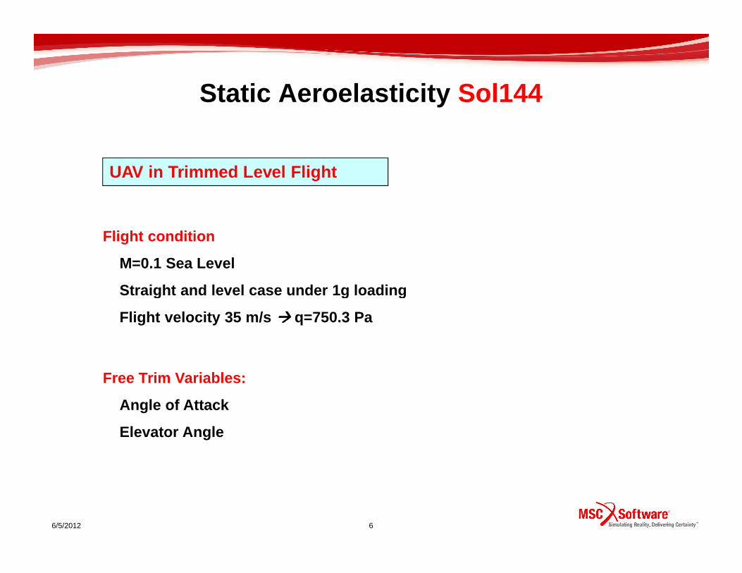
Static Aeroelasticity Sol144
UAV in Trimmed Level Flight
Flight condition
M=0.1 Sea Level
Straight and level case under 1g loading
6/5/2012 6
Straight and level case under 1g loading
Flight velocity 35 m/s ���� q=750.3 Pa
Free Trim Variables:
Angle of Attack
Elevator Angle

Longitudinal Trim - Boundary Conditions
• Nodes which lie on the XZ symmetry plane are constrained to move in that plane
1. Symmetry Condition
Constrained DOFs: T2 R1 R3
Constrained DOFs: 246 $ Displacement Constraints of Load Set : Symmetry ConditionSPC1 3 246 82316 82317 82423 82444 82445 82446
NASTRAN input deck
6/5/2012 7
2. Constraint on Longitudinal Motion
GRID 9999
• Node 9999 (Mass center) is allowed to:Translate in Z-direction - Rotate about the Y-axis
Constrained DOFs: 1246
Constrained DOFs: T1 T2 R1 R3
$ Displacement Constraints of Load Set : Longitudinal MotionSPC1 1 1246 9999
SPC1 3 246 82316 82317 82423 82444 82445 8244682448 83132 83133 83134 83135 83294 83299 83300…..
NASTRAN input deck

Lifting Surface - Flight Loads
1
2
4
3
Left Wing lifting surface
$ ----- Wing_Left ------
CAERO1
SPAN DIVISION
CHORD DIVISION
Name
6/5/2012 8
Wing: 30 Panels span wise 30 Panels chord wise
Stabilizer: 10 Panels span wise 10 Panels chord wise
Elevator: 10 Panels span wise 10 Panels chord wise
CAERO1 CAERO1
Lifting Surfaces
CAERO1
CAERO1
CAERO1
CAERO1
$ ----- Wing_Left ------
CAERO1,300000,5000,,30,30,,,1,
,.35039,-.14,.188351,.402,.35039,-1.325,.188351,.402
NASTRAN input deck
Lifting SurfacesWing
StabilizerElevator
Corner Points
Aero Mesh

Aerodynamic Control Surface - Flight Loads
Hinge Line
AESURF
Hinge
6/5/2012 9
ElevatorControl Surface
Boxes
AESURF,505,ELEV,100,1000
,0.10,0.09
AELIST ,1000,600001,THRU,600099,700000,THRU,700099
$
CORD2R,100,0,1.628,0.,0.034,1.628,0.,1.
,10.,0.,0.034
NASTRAN input deck
Control SurfaceAero Boxes which lie on the Control Surface
Hinge

Groups of Nodes ready for Splining
Spar
Trailing edge
Trailing edge
Wings
Spar
6/5/2012 10
Horizontal Stabilizer (Left side view)
Leading and trailing edge Leading and trailing edge
Elevator (Left side view)
Spar
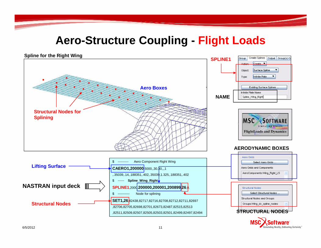
Aero -Structure Coupling - Flight Loads
Structural Nodes for Splining
Aero Boxes
Spline for the Right WingSPLINE1
NAME
$ ---------- Aero Component Right Wing
CAERO1,200000,5000,,30,30,,,1
,.35039,.14,.188351,.402,.35039,1.325,.188351,.402
$ ------ Spline_Wing_Right
SPLINE1,2000,200000,200001,200899,26,0.
$ ----------- Node for splining
SET1,26,82438,82717,82716,82708,82712,82711,82697
,82706,82705,82698,82701,82673,82487,82515,82513
,82511,82509,82507,82505,82503,82501,82499,82497,82494
6/5/2012 11
NASTRAN input deck
STRUCTURAL NODES
AERODYNAMIC BOXES
Lifting Surface
Structural Nodes

AEROELASTIC TRIM VARIABLES
No Superelement Case -Trim Variables in .f06
The UAV is flying with a positive incidence of abou t 2.78 degree and a negative elevator angle of about 2.35 degree
ID LABEL TYPE TRIM STATUS VALUE OF UX
INTERCEPT RIGID BODY FIXED 1.000000E+00
505 ELEV CONTROL SURFACE FREE -4.104785E-02 RADIANS
681 ANGLEA RIGID BODY FREE 4.846353E-02 RADIANS
682 PITCH RIGID BODY FIXED 0.000000E+00 NONDIMEN. RATE
683 URDD3 RIGID BODY FIXED 1.000000E+00 LOAD FACTOR
684 URDD5 RIGID BODY FIXED 0.000000E+00 RAD/S/S PER G
6/5/2012 12

No Superelement Results Overview – Structural
Deformed Structural MeshMax Wing Tip Deflection: 4.85E-03 (m)
6/5/2012 13
Scale interpretation: Model scale
Undeformed Structural Mesh
ANGLE OF ATTACK = 2.776756 DEGREES
ELEV = -2.353 DEGREES

No Superelement Results Overview – Aerodynamic
Deformed Aerodynamic Mesh
Max Wing Tip Deflection: 4.85E-03 (m)
6/5/2012 14
Scale interpretation: Model scale
Undeformed Aerodynamic Mesh
ANGLE OF ATTACK = 2.776756 DEGREES
ELEV = -2.353 DEGREES

1st Superelement “Wings” (Static Condensation)
1) Wings Superelement’s Elements
“Wing” Elements Group
ALL ELEMENTS that belong to the “Wings” Superelement
SUPERELEMENT
ELEMENT GROUP
6/5/2012 15
2) Wings Superelement’s External Nodes (Right wing view)
External Nodes which correspond to SET1 of SPLINE (Superelement 0)
Fuselage Interface Nodes (Superelement 0)
Boundary Nodes
$ Wing
SESET 1 82327 THRU 82374
SESET 1 82437 82439 82483 82484 82485 82486
SESET 1 82488 82490 82491 82492 82493 82495 82496
ALL NODES which are external to the SUPERELEMENT are to be specified
ALL NODES internal to the SUPERELEMENT
External and Interface Nodes
NAME
STATIC CONDENSATION
EXTERNAL NODES

2nd Superelement “Wings” (Static Condensation)
1) Wings Superelement’s Elements
“Wing” Elements Group
ALL ELEMENTS that belong to the “Wings” Superelement
SUPERELEMENT
ELEMENT GROUP
6/5/2012 16
2) Wings Superelement’s External Nodes (Right wing view)
Fuselage Interface Nodes (Superelement 0)
Boundary Nodes
$ Wing interface
SESET 1 82327 THRU 82374
SESET 1 82437 82439 82483 82484 82485 82486
SESET 1 82488 82490 82491 82492 82493 82495 82496
ALL NODES internal to the SUPERELEMENT
NAME
ALL NODES which are external to the SUPERELEMENT are not needed to be specified
Interface Nodes
STATIC CONDENSATION
EXTERNAL NODES

Superelement Cases - Trim Variables in .f06• No Superelement Case
1°°°° Wings Superelement – External & Interface
Superelement 1Superelement 0
Superelement 1
ELEV CONTROL SURFACE FREE -4.104785E-02 RADIANS
ANGLEA RIGID BODY FREE 4.846353E-02 RADIANS
ANGLE OF ATTACK = 2.776756 DEGREES
2°°°° Wings Superelement – Interface Nodes
6/5/2012 17
Nodes
ELEV CONTROL SURFACE FREE -4.105078E-02 RADIANS
ANGLEA RIGID BODY FREE 4.846611E-02 RADIANS
ANGLE OF ATTACK = 2.776904 DEGREES
ELEV CONTROL SURFACE FREE -4.118340E-02 RADIANS
ANGLEA RIGID BODY FREE 4.858012E-02 RADIANS
ANGLE OF ATTACK = 6.488278E-02 RADIANS (2.783436 DEGREES )
Superelement 0 - Residual Superelement 0 - Residual
Nodes
NODES FOR SPLINING CAN BE INTERNAL TO THE SUPERELEM ENT!

1st Superelement Results Overview – Structural
Deformed Structural Mesh
Max Wing Tip Deflection: 4.85E-03 (m)
6/5/2012 18
Scale interpretation: Model scale
Undeformed Structural Mesh
ANGLE OF ATTACK = 2.776904 DEGREES
ELEV = -2.353 DEGREES
Max wing tip deflection as the case of standard sol ution (without Superelement)

1st Superelement Results Overview – Aerodynamic
Deformed Aerodynamic Mesh
Max Wing Tip Deflection: 4.85E-03 (m)
ELEV = -2.353 DEGREES
6/5/2012 19
Scale interpretation: Model scale
Undeformed Aerodynamic Mesh
ANGLE OF ATTACK = 2.783436 DEGREES
Max wing tip deflection as the case of standard sol ution (without Superelement)

2nd Superelement Results Overview – Structural
Deformed Structural MeshMax Wing Tip Deflection: 4.35E-03 (m)
No Superelement Analysis 4.85E-03 (m)
6/5/2012 20
Scale interpretation: Model scale
Undeformed Structural Mesh
ANGLE OF ATTACK = 2.783436 DEGREES
ELEV = -2.360 DEGREES
Max wing tip deflection value is closed to that of standard solution (without superelement)

2nd Superelement Results Overview – Aerodynamic
Deformed Aerodynamic Mesh
Max Wing Tip Deflection: 4.35E-03 (m)
No Superelement Analysis 4.85E-03 (m)
6/5/2012 21
Scale interpretation: Model scale
Undeformed Aerodynamic Mesh
ANGLE OF ATTACK = 2.783436 DEGREES ELEV = -2.360 DEGREES
Max wing tip deflection value is closed to that of standard solution (without superelement)

Fin & Rudder Superelement (Static Condensation)
1) Superelement’s Elements
FinRudder
SUPERELEMENT
NAME
ALL ELEMENTS that belong to the Superelement
ELEMENT GROUP
6/5/2012 22
2) Superelement’s External Nodes
$ Fin_Rudder
SESET 1 101171 THRU 101189
SESET 1 101252 THRU 101267
SESET 1 101269 THRU 101284
ALL NODES which are external to the SUPERELEMENT are not needed to be specified
Fuselage Interface Nodes
Elements Group
Boundary Nodes
ALL NODES internal to the SUPERELEMENT
Interface nodes
ELEMENT GROUP

Stabilizer & Elevator Superelement (Static Condensation)
1) Superelement’s Elements
Elements Group
NAME
SUPERELEMENT
ALL ELEMENTS that belong to the Superelement
Stabilizer
Elevator
ELEMENT GROUP
6/5/2012 23
2) Superelement’s External Nodes
$ Stab_Elev
SESET 1 101171 THRU 101189
SESET 1 101252 THRU 101267
SESET 1 101269 THRU 101284
ALL NODES which are external to the SUPERELEMENT are not needed to be specified
Fuselage Interface Nodes
Elements Group
Boundary Nodes
ALL NODES internal to the SUPERELEMENT
Interface nodes
ELEMENT GROUP
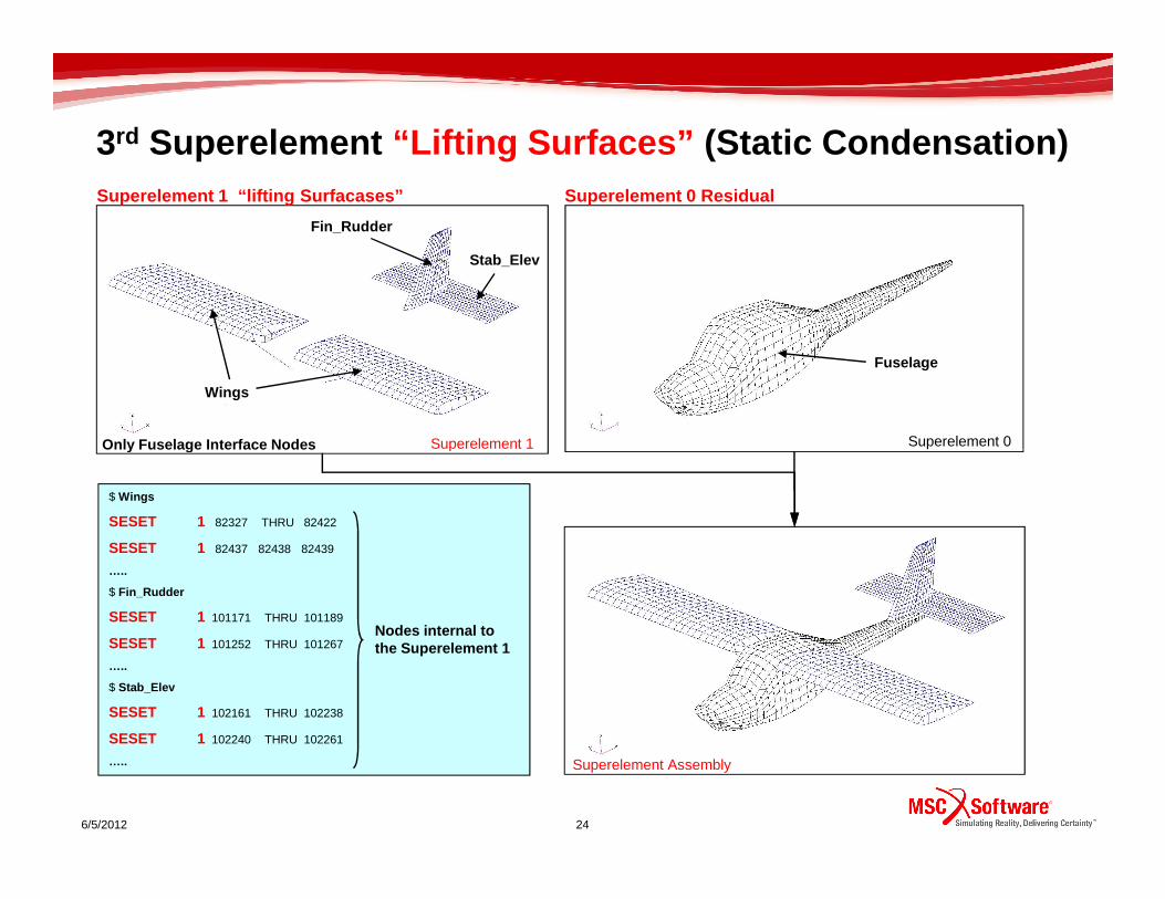
3rd Superelement “Lifting Surfaces” (Static Condensation)
Superelement 0Superelement 1
Wings
Fin_Rudder
Stab_Elev
Fuselage
Only Fuselage Interface Nodes
Superelement 1 “lifting Surfacases” Superelement 0 R esidual
6/5/2012 24
Superelement 1
Superelement Assembly
$ Wings
SESET 1 82327 THRU 82422
SESET 1 82437 82438 82439
…..
$ Fin_Rudder
SESET 1 101171 THRU 101189
SESET 1 101252 THRU 101267
…..
$ Stab_Elev
SESET 1 102161 THRU 102238
SESET 1 102240 THRU 102261
…..
Nodes internal to the Superelement 1
Only Fuselage Interface Nodes

Comparision - Trim Variables in .f06
Superelement 0 - ResidualSuperelement 0 - Residual
Trim Variables
1) No Superelement 2) “Lifting Surfaces” Superelement
6/5/2012 25
ELEV CONTROL SURFACE FREE -3.972963E-02 RADIANS
ANGLEA RIGID BODY FREE 4.858172E-02 RADIANS
ANGLE OF ATTACK = 2.783528 DEGREES
Trim Variables
ELEV CONTROL SURFACE FREE -4.104785E-02 RADIANS
ANGLEA RIGID BODY FREE 4.846353E-02 RADIANS
ANGLE OF ATTACK = 2.776756 DEGREES
Max Wing Tip Deflection: 4.85E-03 (m) Max Wing Tip Deflection: 4.35E-03 (m)
Good results have been achieved!

First Remarks
• Nodes for splining can be internal to the Superelement
• Static reduction leads to results which are in very good accordance
6/5/2012 26
• Static reduction leads to results which are in very good accordance
with standard solution (No Superelement)

Monitor Points
• Monitor points allow to obtain load resultants of t he loads on specified regions of the aircraft.
• Regions can be defined on the structural or the aerodynamic mesh.
6/5/2012 27
aerodynamic mesh.
• MSC Nastran automatically defines structural and aerodynamic monitor points for the overall vehicle and all control surfaces.
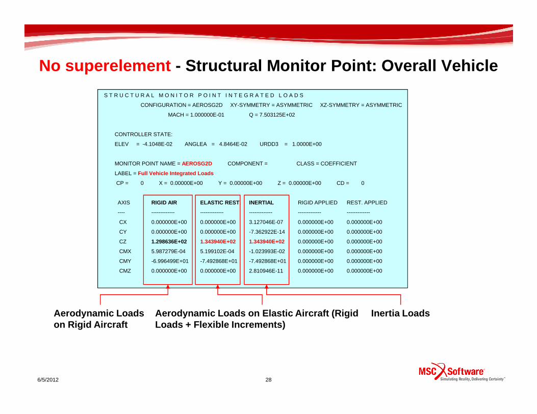
S T R U C T U R A L M O N I T O R P O I N T I N T E G R A T E D L O A D S
CONFIGURATION = AEROSG2D XY-SYMMETRY = ASYMMETRIC XZ-SYMMETRY = ASYMMETRIC
MACH = 1.000000E-01 Q = 7.503125E+02
CONTROLLER STATE:
ELEV = -4.1048E-02 ANGLEA = 4.8464E-02 URDD3 = 1.0000E+00
MONITOR POINT NAME = AEROSG2D COMPONENT = CLASS = COEFFICIENT
LABEL = Full Vehicle Integrated Loads
CP = 0 X = 0.00000E+00 Y = 0.00000E+00 Z = 0.00000E+00 CD = 0
AXIS RIGID AIR ELASTIC REST . INERTIAL RIGID APPLIED REST. APPLIED
No superelement - Structural Monitor Point: Overall Vehicle
---- ------------- ------------- ------------- ------------- -------------
CX 0.000000E+00 0.000000E+00 3.127046E-07 0.000000E+00 0.000000E+00
CY 0.000000E+00 0.000000E+00 -7.362922E-14 0.000000E+00 0.000000E+00
CZ 1.298636E+02 1.343940E+02 1.343940E+02 0.000000E+00 0.000000E+00
CMX 5.987279E-04 5.199102E-04 -1.023993E-02 0.000000E+00 0.000000E+00
CMY -6.996499E+01 -7.492868E+01 -7.492868E+01 0.000000E+00 0.000000E+00
CMZ 0.000000E+00 0.000000E+00 2.810946E-11 0.000000E+00 0.000000E+00
6/5/2012 28
Inertia LoadsAerodynamic Loads on Rigid Aircraft
Aerodynamic Loads on Elastic Aircraft (Rigid Loads + Flexible Increments)

A E R O D Y N A M I C M O N I T O R P O I N T I N T E G R A T E D L O A D S
CONFIGURATION = AEROSG2D XY-SYMMETRY = ASYMMETRIC XZ-SYMMETRY = ASYMMETRIC
MACH = 1.000000E-01 Q = 7.503125E+02
CONTROLLER STATE:
ELEV = -4.1048E-02 ANGLEA = 4.8464E-02 URDD3 = 1.0000E+00
MONITOR POINT NAME = AEROSG2D COMPONENT = CLASS = COEFFICIENT
LABEL = Full Vehicle Integrated Loads
CP = 0 X = 0.00000E+00 Y = 0.00000E+00 Z = 0.00000E+00 CD = 0
AXIS RIGID AIR ELASTIC REST .
No superelement - Aero Monitor Point: Overall Vehicle
---- ------------- -------------
CX 0.000000E+00 0.000000E+00
CY 0.000000E+00 0.000000E+00
CZ 1.298636E+02 1.343940E+02
CMX 5.987279E-04 5.199102E-04
CMY -6.996499E+01 -7.492868E+01
CMZ 0.000000E+00 0.000000E+00
6/5/2012 29
Aerodynamic Loads on Rigid Aircraft
Aerodynamic Loads on Elastic Aircraft (Rigid Loads + Flexible Increments)
There are no Inertia Loads.
The same value evaluated by structural monitor point

S T R U C T U R A L M O N I T O R P O I N T I N T E G R A T E D L O A D S
CONFIGURATION = AEROSG2D XY-SYMMETRY = ASYMMETRIC XZ-SYMMETRY = ASYMMETRIC
MACH = 1.000000E-01 Q = 7.503125E+02
CONTROLLER STATE:
ELEV = -4.1048E-02 ANGLEA = 4.8464E-02 URDD3 = 1.0000E+00
MONITOR POINT NAME = AEROSG2D COMPONENT = CLASS = COEFFICIENT
LABEL = Full Vehicle Integrated Loads
CP = 0 X = 0.00000E+00 Y = 0.00000E+00 Z = 0.00000E+00 CD = 0
AXIS RIGID AIR ELASTIC REST . INERTIAL RIGID APPLIED REST. APPLIED
---- ------------- ------------- ------------- ------------- -------------
1st Superelement - Structural Monitor Point: Overall Vehicle
CX 6.683551E-14 6.781938E-14 2.624707E-07 0.000000E+00 0.000000E+00
CY 1.225743E-14 1.244884E-14 -2.847522E-13 0.000000E+00 0.000000E+00
CZ 1.298701E+02 1.343940E+02 1.343940E+02 0.000000E+00 0.000000E+00
CMX 5.987707E-04 6.439218E-03 -1.023993E-02 0.000000E+00 0.000000E+00
CMY -6.996815E+01 -7.492868E+01 -7.492868E+01 0.000000E+00 0.000000E+00
CMZ 7.287032E-14 7.394231E-14 2.539035E-11 0.000000E+00 0.000000E+00
6/5/2012 30
Inertia LoadsAerodynamic Loads on Rigid Aircraft
Aerodynamic Loads on Elastic Aircraft (Rigid Loads + Flexible Increments)
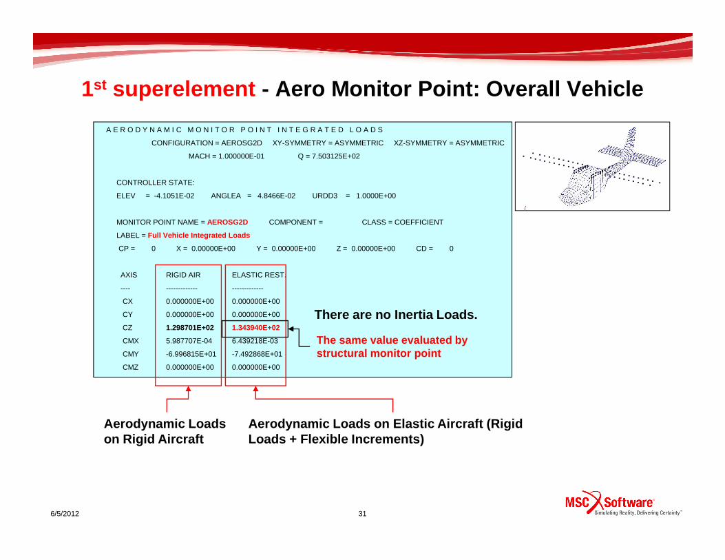
A E R O D Y N A M I C M O N I T O R P O I N T I N T E G R A T E D L O A D S
CONFIGURATION = AEROSG2D XY-SYMMETRY = ASYMMETRIC XZ-SYMMETRY = ASYMMETRIC
MACH = 1.000000E-01 Q = 7.503125E+02
CONTROLLER STATE:
ELEV = -4.1051E-02 ANGLEA = 4.8466E-02 URDD3 = 1.0000E+00
MONITOR POINT NAME = AEROSG2D COMPONENT = CLASS = COEFFICIENT
LABEL = Full Vehicle Integrated Loads
CP = 0 X = 0.00000E+00 Y = 0.00000E+00 Z = 0.00000E+00 CD = 0
AXIS RIGID AIR ELASTIC REST.
1st superelement - Aero Monitor Point: Overall Vehicle
---- ------------- -------------
CX 0.000000E+00 0.000000E+00
CY 0.000000E+00 0.000000E+00
CZ 1.298701E+02 1.343940E+02
CMX 5.987707E-04 6.439218E-03
CMY -6.996815E+01 -7.492868E+01
CMZ 0.000000E+00 0.000000E+00
6/5/2012 31
Aerodynamic Loads on Rigid Aircraft
Aerodynamic Loads on Elastic Aircraft (Rigid Loads + Flexible Increments)
There are no Inertia Loads.
The same value evaluated by structural monitor point

Structural Monitor Points – External Loads FLDS
Monitor Point Location
MONPNT1 (Sol144 & Sol146)
Right Wing – Spar & Trailing Edge Load Contribution
Name
Nodes which correspond to the SET1 of the Spline. External to the superelement
MONPNT1 Ala_dx Carico sull'ala destra
35 al_dx 0 0. 0.0 0.
AECOMP al_dx SET1 50
SET1 50 82327 82352 82354 82356 82358 82360 82362
82364 82366 82368 82370 82372 82487 82494 82497
. . . . .
6/5/2012 32
Nodes Selection
Nodes for Load calculation are the same specified i n the SET1 card for spline interpolation
External to the superelement
Load Components to be monitored
Nodes GROUP

Structural Monitor Point Report in .f061) No Superelement
MONITOR POINT NAME = ALA_DX COMPONENT = AL_DX CLASS = GENERAL
LABEL = CARICO SULL'ALA DESTRA
CP = 0 X = 0.00000E+00 Y = 0.00000E+00 Z = 0.00000E+00 CD = 0
AXIS RIGID AIR ELASTIC REST . INERTIAL RIGID APPLIED REST. APPLIED
CZ 5.875282E+01 5.968761E+01 1.662966E+00 0.000000E+00 0.000000E+00
CMY -2.594139E+01 -2.634859E+01 -8.931566E-01 0.000000E+00 0.000000E+00
MONITOR POINT NAME = ALA_DX COMPONENT = AL_DX CLASS = GENERAL
LABEL = CARICO SULL'ALA DESTRA
2) 1st Superelement Wings – External & Interface Nodes
Superelement 0
MONITOR POINT NAME = ALA_DX COMPONENT = AL_DX CLASS = GENERAL
LABEL = CARICO SULL'ALA DESTRA
CP = 0 X = 0.00000E+00 Y = 0.00000E+00 Z = 0.00000E+00 CD = 0
AXIS RIGID AIR ELASTIC REST . INERTIAL RIGID APPLIED REST. APPLIED
CZ 0.000000E+00 0.000000E+00 0.000000E+00 0.000000E+00 0.000000E+00
CMY 0.000000E+00 0.000000E+00 0.000000E+00 0.000000E+00 0.000000E+00
LABEL = CARICO SULL'ALA DESTRA
CP = 0 X = 0.00000E+00 Y = 0.00000E+00 Z = 0.00000E+00 CD = 0
AXIS RIGID AIR ELASTIC REST. INERTIAL RIGID APPLIED REST. APPLIED
CZ 5.875594E+01 5.969053E+01 1.662966E+00 0.000000E+00 0.000000E+00
CMY -2.594277E+01 -2.634987E+01 -6.877269E+00 0.000000E+00 0.000000E+00
3) 2nd Superelement Wings – Interface Nodes
IT IS NOT POSSIBLE TO MONITOR INTEGRATED LOAD ON NO DES INTERNAL TO THE SUPERELEMENT!
Superelement 0
Superelement 0

Right Wing Load Summation – Flight LoadsNote the Fz terms sum to 59.687, the same as the Structural Monitor point calculation earlier in the “ No Superelement ” case.
Rigid Aerodynamic Loads
Load Summation
STRUCTURAL COMPONENT (NODES)
Right Wing Contribution
Nodes which correspond to the SET1 of the Spline. External to the superelement
LABEL = CARICO SULL'ALA DESTRA
CP = 0 X = 0.00000E+00 Y = 0.00000E+00 Z = 0.00000E+00 CD = 0
AXIS RIGID AIR ELASTIC REST. INERTIAL RIGID APPLIED REST. APPLIED
CZ 5.875282E+01 5.968761E+01 1.662966E+00 0.000000E+00 0.000000E+00
Elastic Increments
Rigid Aerodynamic Loads + Elastic Increments = 5.968779E+01
STRUCTURAL RESULT CASE
RIGID
ELASTIC INCREMENT

Aero Monitor Points – External Loads FLDS
Monitor Point
MONPNT1 (Sol144 & Sol146)
Right Wing Lifting Surface
Panels which contribute to the load calculation
CAERO1_200000
Name
6/5/2012 35
MONPNT1 ALA_DX CARICO SULL’ALA DESTRA
35 ALA_D 0.0 0.0 0.0
AECOMP ALA_D AELIST 26
AELIST 26 200000 THRU 200899
Monitor Point Location
CAERO1 Boxes
Load Components to be monitored
Aero Boxes which contribute to the load calculation
CAERO1 COMPONENT

Aero Monitor Point Report in .f06
MONITOR POINT NAME = ALA_DX COMPONENT = ALA_D CLASS = GENERAL
LABEL = CARICO SULL’ALA DESTRA
CP = 0 X = 0.00000E+00 Y = 0.00000E+00 Z = 0.00000E+00 CD = 0
AXIS RIGID AIR ELASTIC REST .
CZ 5.875282E+01 5.968761E+01
CMY -2.594139E+01 -2.634859E+01
MONITOR POINT NAME = ALA_DX COMPONENT = ALA_D CLASS = GENERAL
LABEL = CARICO SULL’ALA DESTRA
Superelement 0
1) No Superelement
2) 1st Superelement Wings – External & Interface Nodes
The same values evaluated earlier by structural monitor point
MONITOR POINT NAME = ALA_DX COMPONENT = ALA_D CLASS = GENERAL
LABEL = CARICO SULL’ALA DESTRA
CP = 0 X = 0.00000E+00 Y = 0.00000E+00 Z = 0.00000E+00 CD = 0
AXIS RIGID AIR ELASTIC REST .
CZ 5.889306E+01 5.969118E+01
CMY -2.600328E+01 -2.635522E+01
LABEL = CARICO SULL’ALA DESTRA
CP = 0 X = 0.00000E+00 Y = 0.00000E+00 Z = 0.00000E+00 CD = 0
AXIS RIGID AIR ELASTIC REST .
CZ 5.875594E+01 5.969053E+01
CMY -2.594277E+01 -2.634987E+01
IT IS ALWAYS POSSIBLE TO MONITOR INTEGRATED LOAD ON AERODYNAMIC PANELS!
Superelement 0
Superelement 0
3) 2nd Superelement Wings – Interface Nodes
The same values evaluated earlier by structural monitor point

Right Wing Load Summation – Flight LoadsNote the Fz terms sum to about 59.687, the same as the Aero and Structural Monitor Point calculation earlier in the “ No Superelement ” case.
Rigid Aerodynamic Loads
Load Summation
Aerodynamic Component (Boxes)
Aero boxes which contribute to the load calculation
LABEL = CARICO ESTERNO DELL'ALA DESTRA
CP = 0 X = 0.00000E+00 Y = 0.00000E+00 Z = 0.00000E+00 CD = 0
AXIS RIGID AIR ELASTIC REST.
CZ 5.875282E+01 5.968761E+01
Elastic Increments
Rigid Aerodynamic Loads + Elastic Increments = 5.968779+E01
Aerodynamic Result Case
RIGID
ELASTIC INCREMENT
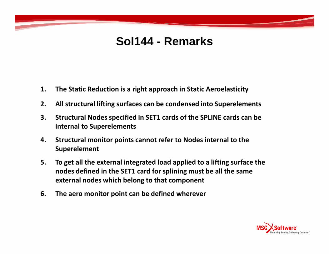
Sol144 - Remarks
1. The Static Reduction is a right approach in Static Aeroelasticity
2. All structural lifting surfaces can be condensed into Superelements
3. Structural Nodes specified in SET1 cards of the SPLINE cards can be
internal to Superelementsinternal to Superelements
4. Structural monitor points cannot refer to Nodes internal to the
Superelement
5. To get all the external integrated load applied to a lifting surface the
nodes defined in the SET1 card for splining must be all the same
external nodes which belong to that component
6. The aero monitor point can be defined wherever

Dynamic Aeroelasticity Sol146
Flight condition
M=0.07
Flight Velocity: Cruise Velocity of 25 m/s at sea l evel
Discrete Gust Response Analysis
6/5/2012 39
Flight Velocity: Cruise Velocity of 25 m/s at sea l evel
Output Results:
Aeroelastic Transfer Matrix
Acceleration of the Structure

Gust Description - Frequency Domain
Excitation
0.4
0.6
0.8
1
1.2
Am
plitu
de
6/5/2012 40
0
0.2
0.4
0 20 40 60 80 100 120 140 160 180 200
Frequency [Hz]
Aeroelastic Transfer MatrixGust
Aeroelastic System

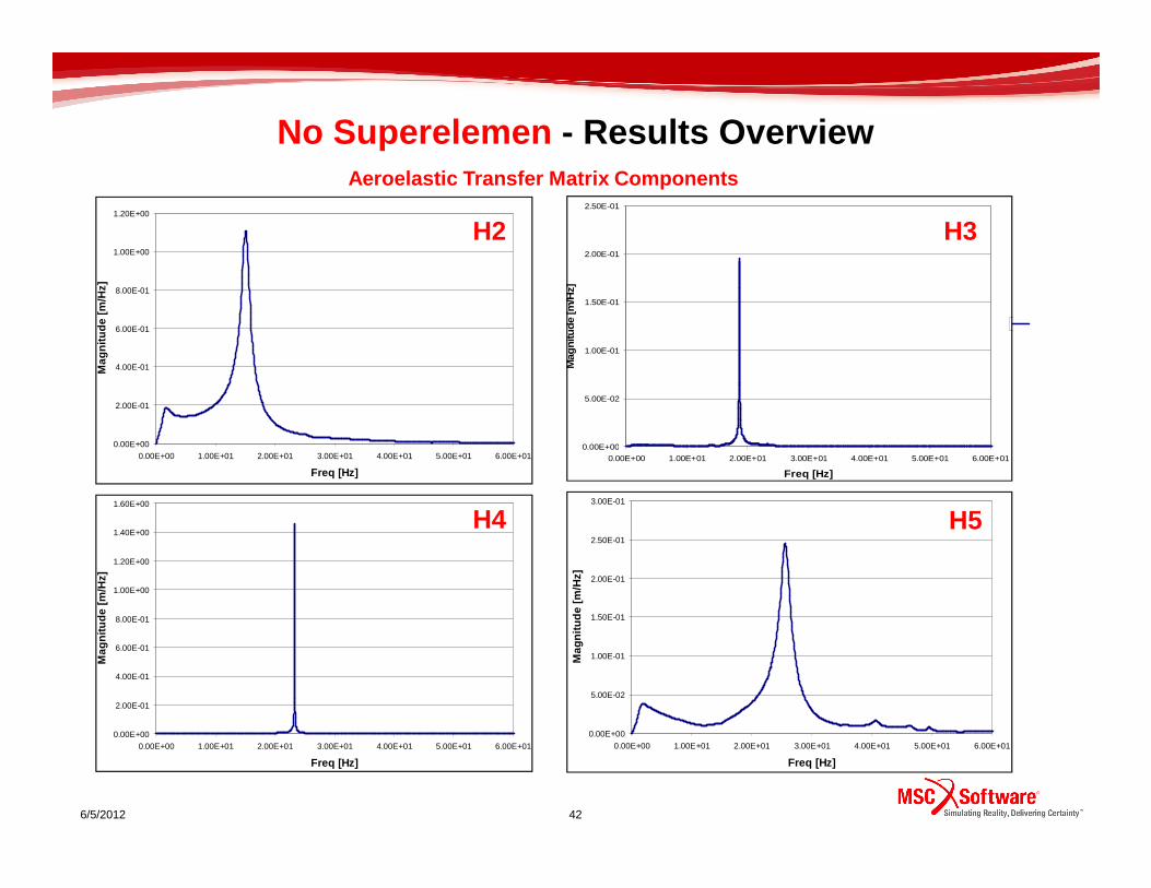
No Superelemen - Results Overview
3.00E-03
3.50E-03
4.00E-03
4.50E-03
Mag
nitu
de [m
/Hz]
Aeroelastic Transfer Matrix – First Component
H1
•The first component of the Aeroelastic Transfer Matr ix shows the structural modes coupling due to the aerodynamic effects
Coupled Structural Modes
18.94 Hz
6/5/2012 41
0.00E+00
5.00E-04
1.00E-03
1.50E-03
2.00E-03
2.50E-03
3.00E-03
0.00E+00 1.00E+01 2.00E+01 3.00E+01 4.00E+01 5.00E+01 6.00E+01
Freq [Hz]
Mag
nitu
de [m
/Hz]
26.4 Hz
15.04 Hz
10.73 Hz
No Superelemen - Results Overview
0.00E+00
2.00E-01
4.00E-01
6.00E-01
8.00E-01
1.00E+00
1.20E+00
Mag
nitu
de [m
/Hz]
0.00E+00
5.00E-02
1.00E-01
1.50E-01
2.00E-01
2.50E-01
Mag
nitu
de [m
/Hz]
H2 H3
Aeroelastic Transfer Matrix Components
6/5/2012 42
0.00E+000.00E+00 1.00E+01 2.00E+01 3.00E+01 4.00E+01 5.00E+01 6.00E+01
Freq [Hz]
0.00E+00
0.00E+00 1.00E+01 2.00E+01 3.00E+01 4.00E+01 5.00E+01 6.00E+01
Freq [Hz]
0.00E+00
2.00E-01
4.00E-01
6.00E-01
8.00E-01
1.00E+00
1.20E+00
1.40E+00
1.60E+00
0.00E+00 1.00E+01 2.00E+01 3.00E+01 4.00E+01 5.00E+01 6.00E+01
Freq [Hz]
Mag
nitu
de [m
/Hz]
0.00E+00
5.00E-02
1.00E-01
1.50E-01
2.00E-01
2.50E-01
3.00E-01
0.00E+00 1.00E+01 2.00E+01 3.00E+01 4.00E+01 5.00E+01 6.00E+01
Freq [Hz]
Mag
nitu
de [m
/Hz]
H4 H5

1st Superelement “Wings” – Static Condensation
$ Wing
SESET 1 82327 THRU 82374
SESET 1 82437 82439 82483 82484 82485 82486
SESET 1 82488 82490 82491 82492 82493 82495 82496
Superelement 1 Superelement 0
NASTRAN input deck

1st Superelement “Wings” - Modal Analysis Overview
External and Interface NodesR E A L E I G E N V A L U E S
MODE CYCLES
NO SUPERELEMENT
1 1 3.948215E-05
2 2 1.768777E-05
3 3 3.037204E-05
4 4 5.694758E-05
5 5 1.195745E-04
6 6 1.734103E-04
7 7 1.073926E+01
8 8 1.505410E+01
9 9 1.895002E+01
R E A L E I G E N V A L U E S
MODE CYCLES
1st WING SUPERELEMENT
1 1 -4.300867E-05
2 2 -8.839101E-06
3 3 1.596211E-05
4 4 6.547200E-05
5 5 1.347224E-04
6 6 1.670944E-04
7 7 1.073913E+01
8 8 1.504033E+01
9 9 1.894949E+01 RESIDUAL
Natural frequencies
6/5/2012 44
9 9 1.895002E+01
10 10 2.428340E+01
11 11 2.649138E+01
12 12 3.537149E+01
13 13 3.603078E+01
14 14 4.236832E+01
15 15 4.377310E+01
16 16 4.697501E+01
17 17 4.954739E+01
18 18 5.051571E+01
19 19 5.381120E+01
20 20 5.604532E+01
21 21 6.583861E+01
22 22 6.772128E+01
23 23 7.153716E+01
24 24 7.217680E+01
25 25 8.437875E+01
9 9 1.894949E+01
10 10 2.428296E+01
11 11 2.648470E+01
12 12 3.534196E+01
13 13 3.602198E+01
14 14 4.236403E+01
15 15 4.371443E+01
16 16 4.695639E+01
17 17 4.943520E+01
18 18 5.050455E+01
19 19 5.380775E+01
20 20 5.603796E+01
21 21 6.583691E+01
22 22 6.766547E+01
23 23 7.150035E+01
24 24 7.212115E+01
25 25 8.352567E+01
There is a very slight difference between natural frequencies
• Static reduction can well describe the dynamic behaviour of the structure in term of natural frequencies and mode shapes
Static Condensation
Same mode shapes
Dynamic local behaviour of the condensed components is taken into account
RESIDUAL

H1
3.50E-03
4.00E-03
4.50E-03
1st Superelement “Wings” Results Overview
Coupled Structural Modes
• Note that the Aeroelastic Response of the system is very closed to the case without Superelement
External and Interface NodesAeroelastic Transfer Matrix – First Component
0.00E+00
5.00E-04
1.00E-03
1.50E-03
2.00E-03
2.50E-03
3.00E-03
0.00E+00 1.00E+01 2.00E+01 3.00E+01 4.00E+01 5.00E+01 6.00E+01
Freq [Hz]
Mag
nitu
de [m
/Hz]
No SuperelementSuperelement
6/5/2012 45
Static Condensation
Residual
Superelement

1st Superelement “Wings” Results Overview• Note that the Aeroelastic Response of the system is very closed to the case without Superelement
Aeroelastic Transfer Matrix – Second ComponentExternal and Interface Nodes
H2
1.00E+00
1.20E+00
Mag
nitu
de [m
/Hz]
6/5/2012 46
Static Condensation
Residual
Superelement
0.00E+00
2.00E-01
4.00E-01
6.00E-01
8.00E-01
0.00E+00 1.00E+01 2.00E+01 3.00E+01 4.00E+01 5.00E+01 6.00E+01
Freq [Hz]
Mag
nitu
de [m
/Hz]
No SuperelementSuperelement

H3
2.00E-01
2.50E-01
Mag
nitu
de [m
/Hz]
1st Superelement “Wings” Results Overview• Note that the Aeroelastic Response of the system is very closed to the case without Superelement
Aeroelastic Transfer Matrix – Third ComponentExternal and Interface Nodes
0.00E+00
5.00E-02
1.00E-01
1.50E-01
0.00E+00 1.00E+01 2.00E+01 3.00E+01 4.00E+01 5.00E+01 6.00E+01
Freq [Hz]
Mag
nitu
de [m
/Hz] No Superelement
Superelement
6/5/2012 47
Static Condensation
Residual
Superelement

H4
1.20E+00
1.40E+00
1.60E+00
Mag
nitu
de [m
/Hz]
1st Superelement “Wings” Results Overview• Note that the Aeroelastic Response of the system is very closed to the case without Superelement
Aeroelastic Transfer Matrix – Fourth ComponentExternal and Interface Nodes
0.00E+00
2.00E-01
4.00E-01
6.00E-01
8.00E-01
1.00E+00
0.00E+00 1.00E+01 2.00E+01 3.00E+01 4.00E+01 5.00E+01 6.00E+01
Freq [Hz]
Mag
nitu
de [m
/Hz] No Superelement
Superelement
6/5/2012 48
Static Condensation
Residual
Superelement

1st Superelement “Wings” Results Overview• Note that the Aeroelastic Response of the system is very closed to the case without Superelement
Aeroelastic Transfer Matrix – Fifth ComponentExternal and Interface Nodes
H5
2.50E-01
3.00E-01
6/5/2012 49
Static Condensation
Residual
Superelement
0.00E+00
5.00E-02
1.00E-01
1.50E-01
2.00E-01
0.00E+00 1.00E+01 2.00E+01 3.00E+01 4.00E+01 5.00E+01 6.00E+01
Freq [Hz]
Mag
nitu
de [m
/Hz] No Superelement
Superelement

1st Superelement “Wings” Results Overview• Note that the Aeroelastic Response of the system is very closed to the case without Superelement
Aeroelastic Transfer Matrix – Eleventh Component
H11
2.50E-01
3.00E-01
Mag
nitu
de [m
/Hz]
External and Interface Nodes
6/5/2012 50
Static Condensation
0.00E+00
5.00E-02
1.00E-01
1.50E-01
2.00E-01
0.00E+00 1.00E+01 2.00E+01 3.00E+01 4.00E+01 5.00E+01 6.00E+01
Freq [Hz]
Mag
nitu
de [m
/Hz]
No Superelement
Superelement
Residual
Superelement

1st Superelement “Wings” Results Overview
Wing Tip Acceleration
2.00E+03
2.50E+03
Mag
nitu
de [m
/s^2
/Hz]
• Note that the Aeroelastic Response of the system is very closed to the case without Superelement
Tip Node
Acceleration of the Structure
6/5/2012
0.00E+00
5.00E+02
1.00E+03
1.50E+03
0.00E+00 1.00E+01 2.00E+01 3.00E+01 4.00E+01 5.00E+01 6.00E+01
Freq [Hz]
Mag
nitu
de [m
/s^2
/Hz]
No SuperelementSuperelement
Static Condensation

1st Superelement “Wings” Results Overview
Stabilizer Tip Acceleration
1.20E+03
1.40E+03
1.60E+03
1.80E+03
Mag
nitu
de [m
/s^2
/Hz]
• Note that the Aeroelastic Response of the system is very closed to the case without Superelement
Tip Node
Acceleration of the Structure
6/5/2012
0.00E+00
2.00E+02
4.00E+02
6.00E+02
8.00E+02
1.00E+03
1.20E+03
0.00E+00 1.00E+01 2.00E+01 3.00E+01 4.00E+01 5.00E+01 6.00E+01
Freq [Hz]
Mag
nitu
de [m
/s^2
/Hz]
No SuperelementSuperelement
Static Condensation

1st Superelement “Wings” Results Overview
Fin Tip Acceleration
6.00E+02
7.00E+02
8.00E+02
Mag
nitu
de [m
/s^2
/Hz]
• Note that the Aeroelastic Response of the system is very closed to the case without Superelement
Tip Node
Acceleration of the Structure
6/5/2012
0.00E+00
1.00E+02
2.00E+02
3.00E+02
4.00E+02
5.00E+02
0.00E+00 1.00E+01 2.00E+01 3.00E+01 4.00E+01 5.00E+01 6.00E+01
Freq [Hz]
Mag
nitu
de [m
/s^2
/Hz]
No Superelement
Superelement
Static Condensation

1st Superelement “Wings” Results Overview
C.G. Acceleration
2.00E+02
2.50E+02
Mag
nitu
de [m
/s^2
/Hz]
• Note that the Aeroelastic Response of the system is very closed to the case without Superelement
C.G. Node
Acceleration of the Structure
6/5/2012
0.00E+00
5.00E+01
1.00E+02
1.50E+02
0.00E+00 1.00E+01 2.00E+01 3.00E+01 4.00E+01 5.00E+01 6.00E+01
Freq [Hz]
Mag
nitu
de [m
/s^2
/Hz]
No Superelement
Superelement
Static Condensation Static reduction leads to right results!
Component Mode Synthesis is not needed!

3rd Superelement “Lifting Surfaces” – Static Condensation
Superelement 1 Superelement 0
6/5/2012
Superelement 1
$ Wings
SESET 1 82327 THRU 82422
SESET 1 82437 82438 82439
…..
$ Fin_Rudder
SESET 1 101171 THRU 101189
SESET 1 101252 THRU 101267
…..
$ Stab_Elev
SESET 1 102161 THRU 102238
SESET 1 102240 THRU 102261
…..
NASTRAN input deck
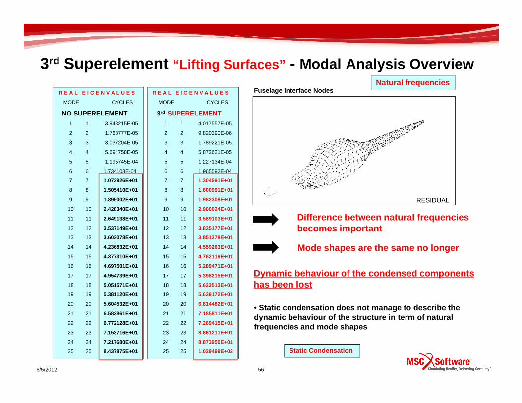
3rd Superelement “Lifting Surfaces” - Modal Analysis Overview
Fuselage Interface NodesR E A L E I G E N V A L U E S
MODE CYCLES
NO SUPERELEMENT
1 1 3.948215E-05
2 2 1.768777E-05
3 3 3.037204E-05
4 4 5.694758E-05
5 5 1.195745E-04
6 6 1.734103E-04
7 7 1.073926E+01
8 8 1.505410E+01
9 9 1.895002E+01
R E A L E I G E N V A L U E S
MODE CYCLES
3rd SUPERELEMENT
1 1 4.017557E-05
2 2 9.820390E-06
3 3 1.789221E-05
4 4 5.872621E-05
5 5 1.227134E-04
6 6 1.965592E-04
7 7 1.304591E+01
8 8 1.600991E+01
9 9 1.982308E+01 RESIDUAL
Natural frequencies
6/5/2012 56
9 9 1.895002E+01
10 10 2.428340E+01
11 11 2.649138E+01
12 12 3.537149E+01
13 13 3.603078E+01
14 14 4.236832E+01
15 15 4.377310E+01
16 16 4.697501E+01
17 17 4.954739E+01
18 18 5.051571E+01
19 19 5.381120E+01
20 20 5.604532E+01
21 21 6.583861E+01
22 22 6.772128E+01
23 23 7.153716E+01
24 24 7.217680E+01
25 25 8.437875E+01
9 9 1.982308E+01
10 10 2.900024E+01
11 11 3.589103E+01
12 12 3.835177E+01
13 13 3.851378E+01
14 14 4.559263E+01
15 15 4.762119E+01
16 16 5.289471E+01
17 17 5.398215E+01
18 18 5.622513E+01
19 19 5.639172E+01
20 20 6.814482E+01
21 21 7.185811E+01
22 22 7.269415E+01
23 23 8.861211E+01
24 24 8.873950E+01
25 25 1.029499E+02
Difference between natural frequencies becomes important
• Static condensation does not manage to describe the dynamic behaviour of the structure in term of natur al frequencies and mode shapes
Static Condensation
Mode shapes are the same no longer
Dynamic behaviour of the condensed components has been lost
RESIDUAL

3rd Superelement “Lifting Surfaces” - Modal Analysis Overview
First Mode First Mode
Static Condensation
6/5/2012 57
Second Mode Second Mode
SuperelementNo Superelement
No Superelement Superelement

3rd Superelement “Lifting Surfaces” Modal Analysis Overview
Third Mode Third Mode
Static Condensation
6/5/2012 58
Fourth Mode Fourth Mode
No Superelement
No Superelement
Superelement
Superelement

3rd Superelement “Lifting Surfaces” Modal Analysis Overview
Fifth Mode Fifth Mode
Static Condensation
6/5/2012 59
Sixth Mode Sixth Mode
No Superelement
No Superelement
Superelement
Superelement

3rd Superelement “Lifting Surfaces” - Results Overview
Aeroelastic Transfer Matrix – First Component
Coupled Structural Modes
• Note that the Aeroelastic Response of the system di ffers from the case without Superelement
Fuselage Interface Nodes
H1 H1
7.00E-03
8.00E-03
6/5/2012 60
0.00E+00
1.00E-03
2.00E-03
3.00E-03
4.00E-03
5.00E-03
6.00E-03
0.00E+00 1.00E+01 2.00E+01 3.00E+01 4.00E+01 5.00E+01 6.00E+01
Freq [Hz]
Mag
nitu
de [m
/Hz]
No SuperelementSuperelement
Static Condensation
Residual
Superelement

3rd Superelement “Lifting Surfaces” - Results Overview
Aeroelastic Transfer Matrix – Second Component
H2
1.20E+00
1.40E+00
Fuselage Interface Nodes
• Note that the Aeroelastic Response of the system di ffers from the case without Superelement
6/5/2012 61
0.00E+00
2.00E-01
4.00E-01
6.00E-01
8.00E-01
1.00E+00
0.00E+00 1.00E+01 2.00E+01 3.00E+01 4.00E+01 5.00E+01 6.00E+01
Freq [Hz]
Mag
nitu
de [m
/Hz]
No Superelement
Superelement
Static Condensation
Residual
Superelement
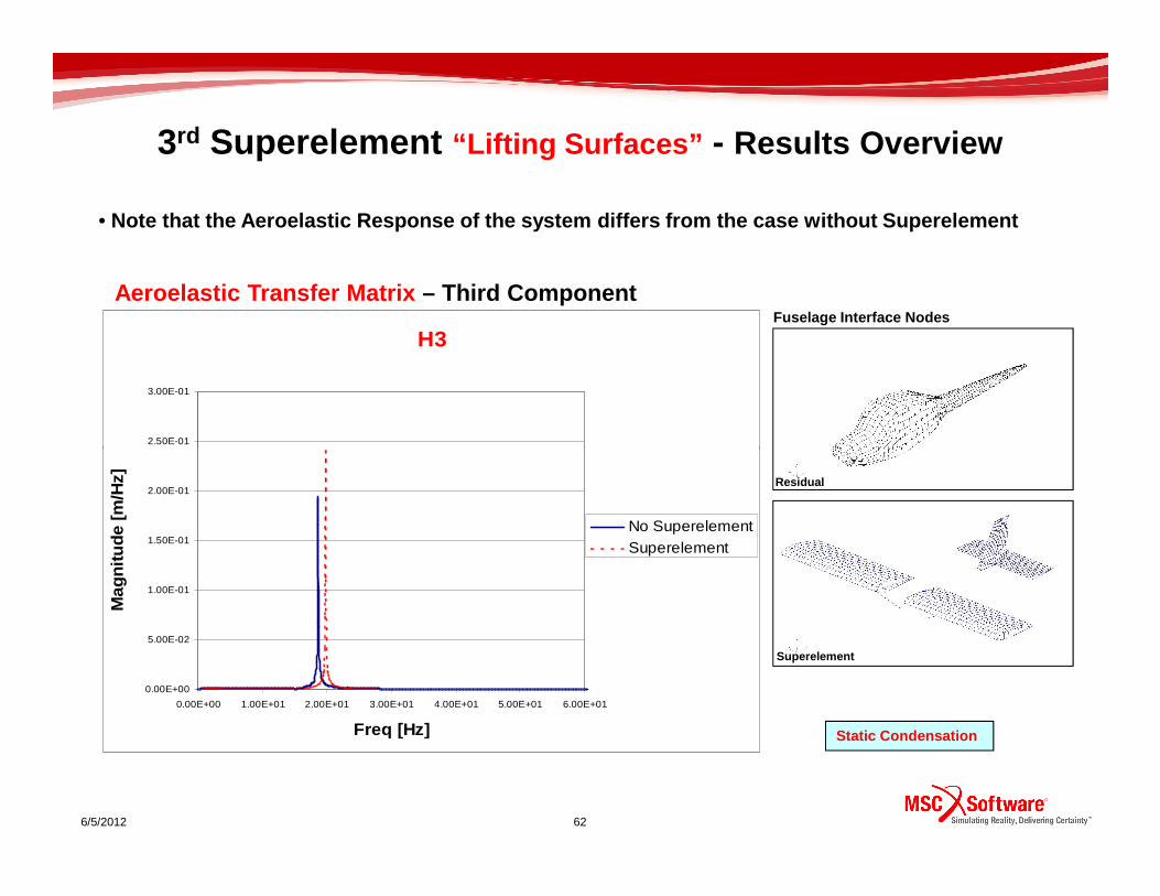
3rd Superelement “Lifting Surfaces” - Results Overview
Aeroelastic Transfer Matrix – Third Component
Coupled Structural ModesH1 H3
2.50E-01
3.00E-01
Fuselage Interface Nodes
• Note that the Aeroelastic Response of the system di ffers from the case without Superelement
6/5/2012 62
0.00E+00
5.00E-02
1.00E-01
1.50E-01
2.00E-01
0.00E+00 1.00E+01 2.00E+01 3.00E+01 4.00E+01 5.00E+01 6.00E+01
Freq [Hz]
Mag
nitu
de [m
/Hz]
No SuperelementSuperelement
Static Condensation
Residual
Superelement

3rd Superelement “Lifting Surfaces” - Results Overview
Aeroelastic Transfer Matrix – Fourth Component
Coupled Structural ModesH1 H4
1.40E+00
1.60E+00
Fuselage Interface Nodes
• Note that the Aeroelastic Response of the system di ffers from the case without Superelement
6/5/2012 63
0.00E+00
2.00E-01
4.00E-01
6.00E-01
8.00E-01
1.00E+00
1.20E+00
0.00E+00 1.00E+01 2.00E+01 3.00E+01 4.00E+01 5.00E+01 6.00E+01
Freq [Hz]
Mag
nitu
de [m
/Hz]
No Superelement
Superelement
Static Condensation
Residual
Superelement

3rd Superelement “Lifting Surfaces” - Results Overview
Aeroelastic Transfer Matrix – Fifth Component
H5
2.50E-01
3.00E-01
Fuselage Interface Nodes
• Note that the Aeroelastic Response of the system di ffers from the case without Superelement
6/5/2012 64
0.00E+00
5.00E-02
1.00E-01
1.50E-01
2.00E-01
0.00E+00 1.00E+01 2.00E+01 3.00E+01 4.00E+01 5.00E+01 6.00E+01
Freq [Hz]
Mag
nitu
de [m
/Hz]
No SuperelementSuperelement
Static Condensation
Residual
Superelement
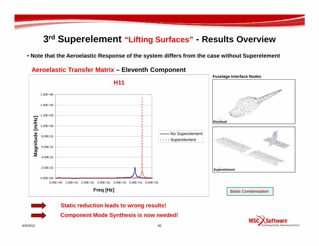
3rd Superelement “Lifting Surfaces” - Results Overview
Aeroelastic Transfer Matrix – Eleventh Component
H11
1.20E+00
1.40E+00
1.60E+00
Mag
nitu
de [m
/Hz]
Fuselage Interface Nodes
Residual
• Note that the Aeroelastic Response of the system di ffers from the case without Superelement
6/5/2012 65
0.00E+00
2.00E-01
4.00E-01
6.00E-01
8.00E-01
1.00E+00
0.00E+00 1.00E+01 2.00E+01 3.00E+01 4.00E+01 5.00E+01 6.00E+01
Freq [Hz]
Mag
nitu
de [m
/Hz]
No Superelement
Superelement
Static Condensation
Residual
Superelement
Static reduction leads to wrong results!
Component Mode Synthesis is now needed!
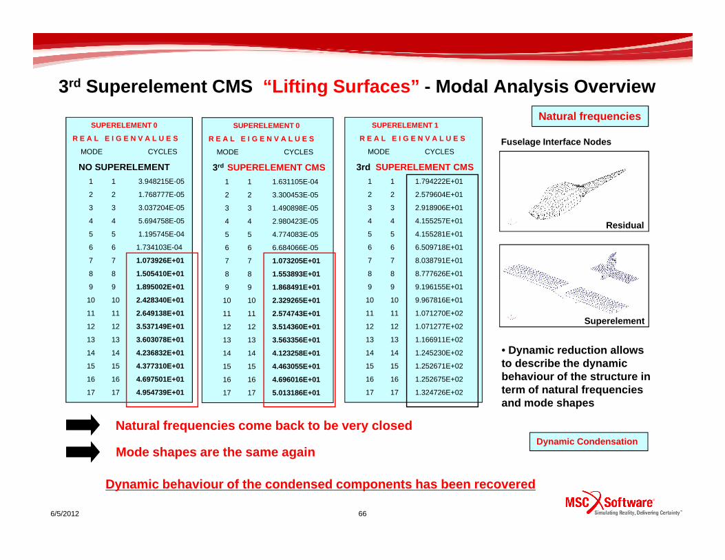
3rd Superelement CMS “Lifting Surfaces” - Modal Analysis Overview
Fuselage Interface Nodes
SUPERELEMENT 0
R E A L E I G E N V A L U E S
MODE CYCLES
NO SUPERELEMENT
1 1 3.948215E-05
2 2 1.768777E-05
3 3 3.037204E-05
4 4 5.694758E-05
5 5 1.195745E-04
6 6 1.734103E-04
7 7 1.073926E+01
8 8 1.505410E+01
Residual
SUPERELEMENT 1
R E A L E I G E N V A L U E S
MODE CYCLES
3rd SUPERELEMENT CMS
1 1 1.794222E+01
2 2 2.579604E+01
3 3 2.918906E+01
4 4 4.155257E+01
5 5 4.155281E+01
6 6 6.509718E+01
7 7 8.038791E+01
8 8 8.777626E+01
SUPERELEMENT 0
R E A L E I G E N V A L U E S
MODE CYCLES
3rd SUPERELEMENT CMS
1 1 1.631105E-04
2 2 3.300453E-05
3 3 1.490898E-05
4 4 2.980423E-05
5 5 4.774083E-05
6 6 6.684066E-05
7 7 1.073205E+01
8 8 1.553893E+01
Natural frequencies
6/5/2012 66
9 9 1.895002E+01
10 10 2.428340E+01
11 11 2.649138E+01
12 12 3.537149E+01
13 13 3.603078E+01
14 14 4.236832E+01
15 15 4.377310E+01
16 16 4.697501E+01
17 17 4.954739E+01
Natural frequencies come back to be very closed
• Dynamic reduction allows to describe the dynamic behaviour of the structure in term of natural frequencies and mode shapes
Dynamic Condensation Mode shapes are the same again
Dynamic behaviour of the condensed components has b een recovered
9 9 9.196155E+01
10 10 9.967816E+01
11 11 1.071270E+02
12 12 1.071277E+02
13 13 1.166911E+02
14 14 1.245230E+02
15 15 1.252671E+02
16 16 1.252675E+02
17 17 1.324726E+02
9 9 1.868491E+01
10 10 2.329265E+01
11 11 2.574743E+01
12 12 3.514360E+01
13 13 3.563356E+01
14 14 4.123258E+01
15 15 4.463055E+01
16 16 4.696016E+01
17 17 5.013186E+01
Superelement

3rd Superelement CMS “Lifting Surfaces” - Modal Analysis Overview
First Mode First ModeDynamic Condensation
6/5/2012 67
Superelement CMSNo Superelement
No Superelement Superelement CMS
Second Mode Second Mode

3rd Superelement “Lifting Surfaces” Modal Analysis Overview
Third Mode Third ModeDynamic Condensation
6/5/2012 68
Superelement CMSNo Superelement
No Superelement Superelement CMS
Fourth Mode Fourth Mode

3rd Superelement “Lifting Surfaces” Modal Analysis Overview
Fifth Mode Fifth ModeDynamic Condensation
6/5/2012 69
Sixth Mode Sixth Mode
Superelement CMSNo Superelement
No Superelement Superelement CMS

3rd Superelement “Lifting Surfaces” – Results Overview
Fuselage Interface NodesH1
4.50E-03
Aeroelastic Transfer Matrix – First Component
• Note that the Aeroelastic Response of the System is very closed to the case without Superelement
6/5/2012 70
0.00E+00
5.00E-04
1.00E-03
1.50E-03
2.00E-03
2.50E-03
3.00E-03
3.50E-03
4.00E-03
0.00E+00 1.00E+01 2.00E+01 3.00E+01 4.00E+01 5.00E+01 6.00E+01
Freq [Hz]
Mag
nitu
de [m
/Hz]
No Superelement
Superelement CMS
Dynamic Condensation
Residual
Superelement

3rd Superelement “Lifting Surfaces” - Dynamic Condensation
H2
1.20E+00
Fuselage Interface NodesAeroelastic Transfer Matrix – Second Component
• Note that the Aeroelastic Response of the System is very closed to the case without Superelement
6/5/2012 71
0.00E+00
2.00E-01
4.00E-01
6.00E-01
8.00E-01
1.00E+00
0.00E+00 1.00E+01 2.00E+01 3.00E+01 4.00E+01 5.00E+01 6.00E+01
Freq [Hz]
Mag
nitu
de [m
/Hz]
No Superelement
Superelement CMS
Dynamic Condensation
Residual
Superelement

3rd Superelement “Lifting Surfaces” - Dynamic Condensation
H3
3.00E-01
Fuselage Interface NodesAeroelastic Transfer Matrix – Third Component
• Note that the Aeroelastic Response of the System is very closed to the case without Superelement
6/5/2012 72
0.00E+00
5.00E-02
1.00E-01
1.50E-01
2.00E-01
2.50E-01
0.00E+00 1.00E+01 2.00E+01 3.00E+01 4.00E+01 5.00E+01 6.00E+01
Freq [Hz]
Mag
nitu
de [m
/Hz]
No Superelement
Superelement CMS
Dynamic Condensation
Residual
Superelement

3rd Superelement “Lifting Surfaces” - Dynamic Condensation
H4
1.60E+00
Fuselage Interface NodesAeroelastic Transfer Matrix – Forth Component
• Note that the Aeroelastic Response of the System is very closed to the case without Superelement
6/5/2012 73
0.00E+00
2.00E-01
4.00E-01
6.00E-01
8.00E-01
1.00E+00
1.20E+00
1.40E+00
0.00E+00 1.00E+01 2.00E+01 3.00E+01 4.00E+01 5.00E+01 6.00E+01
Freq [Hz]
Mag
nitu
de [m
/Hz]
No Superelement
Superelement CMS
Dynamic Condensation
Residual
Superelement

3rd Superelement “Lifting Surfaces” - Dynamic Condensation
H5
3.00E-01
Fuselage Interface NodesAeroelastic Transfer Matrix – Fifth Component
• Note that the Aeroelastic Response of the System is very closed to the case without Superelement
6/5/2012 74
0.00E+00
5.00E-02
1.00E-01
1.50E-01
2.00E-01
2.50E-01
0.00E+00 1.00E+01 2.00E+01 3.00E+01 4.00E+01 5.00E+01 6.00E+01
Freq [Hz]
Mag
nitu
de [m
/Hz]
No SuperelementSuperelement CMS
Dynamic Condensation
Residual
Superelement
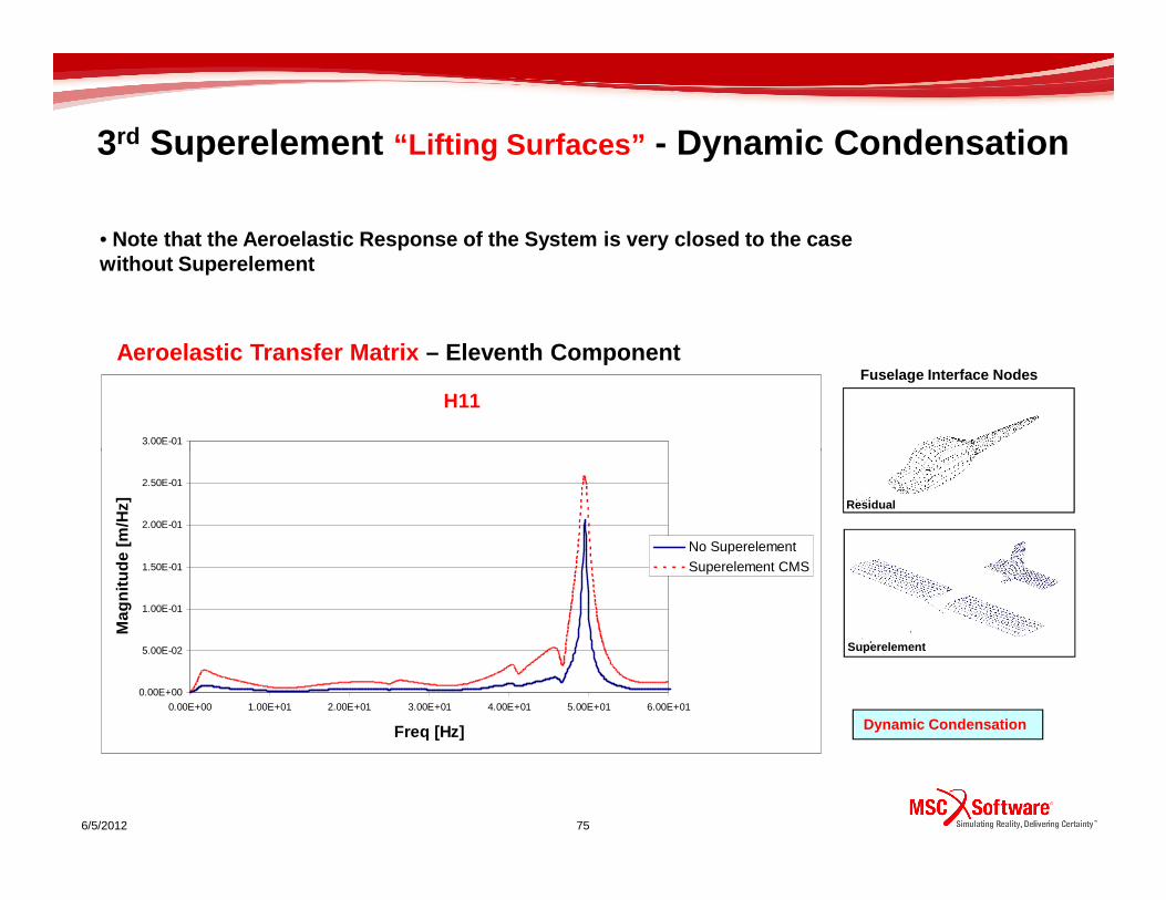
3rd Superelement “Lifting Surfaces” - Dynamic Condensation
H11
3.00E-01
Fuselage Interface NodesAeroelastic Transfer Matrix – Eleventh Component
• Note that the Aeroelastic Response of the System is very closed to the case without Superelement
6/5/2012 75
0.00E+00
5.00E-02
1.00E-01
1.50E-01
2.00E-01
2.50E-01
0.00E+00 1.00E+01 2.00E+01 3.00E+01 4.00E+01 5.00E+01 6.00E+01
Freq [Hz]
Mag
nitu
de [m
/Hz]
No Superelement
Superelement CMS
Dynamic Condensation
Residual
Superelement

1st Superelement “Wings” Results Overview
Tip NodeWing Tip Acceleration
No SuperelementStatic SuperelementSuperelement CMS
Superelement
Acceleration of the structure
Comparison
Mag
nitu
de [m
/s2 /
Hz]
6/5/2012
Static vs. Dynamic Condensation
Residual
Mag
nitu
de [m
/s
[Hz]

1st Superelement “Wings” Results Overview
Tip Node
No SuperelementStatic SuperelementSuperelement CMS
Stabilizer Tip Acceleration
Superelement
Comparison
Acceleration of the structure
Mag
nitu
de [m
/s2 /
Hz]
6/5/2012
Residual
Static vs. Dynamic Condensation
Mag
nitu
de [m
/s
[Hz]

1st Superelement “Wings” Results Overview
Tip Node
No SuperelementStatic SuperelementSuperelement CMS
Fin Tip Acceleration
Superelement
Comparison
Acceleration of the structure
Mag
nitu
de [m
/s2 /
Hz]
6/5/2012
Residual
Static vs. Dynamic Condensation
Mag
nitu
de [m
/s
[Hz]

1st Superelement “Wings” Results Overview
C.G. Node
No SuperelementStatic SuperelementSuperelement CMS
C.G. Acceleration
Superelement
Comparison
Acceleration of the structure
Mag
nitu
de [m
/s2 /
Hz]
6/5/2012
Residual
Static vs. Dynamic Condensation
Static reduction is not enough for this Superelemen t model!
Component Mode Synthesis leads to right results!
Mag
nitu
de [m
/s
[Hz]

Dynamic Aeroelasticity Sol146
Discrete Gust Response Analysis
Flight condition
M=0.07
Flight Velocity: Cruise Velocity of 25 m/s at sea l evel
6/5/2012 80
Flight Velocity: Cruise Velocity of 25 m/s at sea l evel
Output Results:
Time History of the Response of the UAV

Gust Description – Time Domain
EASA CS 23.333 Flight Envelope
s = Distance penetrated into gust
C = Mean geometric chord of wing
Ude = Derived gust velocity
Gust Envelope
Shape of the gust
The aeroplane is assumed to be subjected to symmetrical vertical gusts in level flight.
Gust Profile
6/5/2012 81
Gust Profile
0
1
2
3
4
5
6
7
8
9
0 0.05 0.1 0.15 0.2 0.25 0.3 0.35 0.4
Time (s)
Vel
ocity
(m
/s) • UAV Flight Velocity 25 m/s
• Ude 15.24 m/s

3rd Superelement “Wings” Results Overview
• The aeroelastic transient response of the center of mass is quite the same
C.G. Node
C.G. Acceleration
4
6No SuperelementSuperelement
Time History of a node located at the UAV center of mass
No Component Mode Synthesis
6/5/2012
-6
-4
-2
0
2
0 0.2 0.4 0.6 0.8 1 1.2 1.4 1.6 1.8 2
Time [s]
Acc
eler
atio
n [g
]
0.6 0.8 1
Static reduction allows to identify the global dyna mic behaviour
Static Condensation

3rd Superelement “Wings” Results Overview
Wing Tip Acceleration
4
6No SuperelementSuperelement
Tip Node
Time History of a node internal to the Superelement at wing tip station
• The aeroelastic transient response at wing tip stat ion is different from the case without Superelement
No Component Mode Synthesis
Static Condensation
6/5/2012
-6
-4
-2
0
2
0 0.2 0.4 0.6 0.8 1 1.2 1.4 1.6 1.8 2
Time [s]
Acc
eler
atio
n [g
]
0.6 0.8 1
Local dynamic information has been lost

3rd Superelement “Wings” Results Overview
• The aeroelastic transient response of the center of mass is quite the same
C.G. Node
C.G. Acceleration
4
6No SuperelementSuperelement
Time History of a node located at the UAV center of mass
Component Mode Synthesis
6/5/2012
-6
-4
-2
0
2
0 0.2 0.4 0.6 0.8 1 1.2 1.4 1.6 1.8 2
Time [s]
Acc
eler
atio
n [g
]
0.6 0.8 1 Dynamic Condensation
Dynamic reduction allows to identify the global dyn amic behaviour

Wing Tip Acceleration
4
6No SuperelementSuperelement
3rd Superelement “Wings” Results Overview
Tip Node
Time History of a node internal to the Superelement at wing tip station
• The aeroelastic transient response at wing tip stat ion is very closed to that of the case without Superelement
Component Mode Synthesis
-6
-4
-2
0
2
0 0.2 0.4 0.6 0.8 1 1.2 1.4 1.6 1.8 2
Time [s]
Acc
eler
atio
n [g
]
Dynamic Condensation
6/5/2012
Local dynamic information has been recoverd
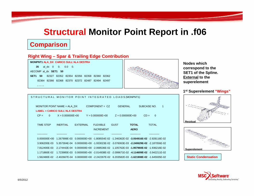
Structural Monitor Point Report in .f06
MONPNT1 ALA_DX CARICO SULL’ALA DESTRA
35 al_dx 0 0. 0.0 0.
AECOMP al_dx SET1 50
SET1 50 82327 82352 82354 82356 82358 82360 82362
82364 82366 82368 82370 82372 82487 82494 82497
. . . . .
Right Wing – Spar & Trailing Edge Contribution
S T R U C T U R A L M O N I T O R P O I N T I N T E G R A T E D L O A D S (MONPNT1)
Nodes which correspond to the SET1 of the Spline. External to the superelement
1st Superelement “Wings”
Comparison
Static Condensation
6/5/2012
S T R U C T U R A L M O N I T O R P O I N T I N T E G R A T E D L O A D S (MONPNT1)
MONITOR POINT NAME = ALA_DX COMPONENT = CZ GENERAL SUBCASE NO. 1
LABEL = CARICO SULL'ALA DESTRA
CP = 0 X = 0.000000E+00 Y = 0.000000E+00 Z = 0.000000E+00 CD = 0
TIME STEP INERTIAL EXTERNAL FLEXIBLE GUST TOTAL TOTAL
INCREMENT AERO
------------ ------------ ------------ ------------ ------------ ------------ ------------
0.000000E+00 1.267999E-03 0.000000E+00 -1.808554E-02 -1.246362E-02 -3.054916E-02 -2.928116E-02
3.906200E-03 5.357304E-04 0.000000E+00 -1.933023E-02 -3.076063E-03 -2.240629E-02 -2.187056E-02
7.812400E-03 2.174442E-04 0.000000E+00 -2.068536E-02 1.105762E-03 -1.957960E-02 -1.936216E-02
1.171860E-02 1.723985E-03 0.000000E+00 -2.014938E-02 -2.099671E-02 -4.114609E-02 -3.942211E-02
1.562480E-02 -2.402667E-04 0.000000E+00 -2.242267E-02 6.203582E-03 -1.621908E-02 -1.645935E-02
Residual
Superelement

Structural Monitor Point – Results Overview
Total Aero
0.00E+00
1.00E+02
2.00E+02
3.00E+02
Aer
o Lo
ad [N
]
Superelement
No Superelement
Right Wing – Spar & Trailing Edge Contribution
Comparison
1st Superelement “Wings”
6/5/2012
-3.00E+02
-2.00E+02
-1.00E+02
0.00E+00
0 0.2 0.4 0.6 0.8 1 1.2 1.4 1.6 1.8 2
Time [s]
Aer
o Lo
ad [N
]
Static Condensation
0.6 0.8 1
Static Condensation allows to obtain results compar able with standard solution
Residual
Superelement

Aero Monitor Point Report in .f06No Component Mode Synthesis
A E R O D Y N A M I C M O N I T O R P O I N T I N T E G R A T E D L O A D S (MONPNT1)
MONPNT1 ALA_DX CARICO SULL’ALA DESTRA
35 ALA_D 0.0 0.0 0.0
AECOMP ALA_D AELIST 26
AELIST 26 200000 THRU 200899
Right Wing Lifting SurfacePanels which contribute to the load calculation
Comparison
3rd Superelement “Lifting Surfaces”
Static Condensation
6/5/2012
MONITOR POINT NAME = ALA_DX COMPONENT = CZ GENERAL SUBCASE NO. 1
LABEL = CARICO SULL’ALA DESTRA
CP = 0 X = 0.000000E+00 Y = 0.000000E+00 Z = 0.000000E+00 CD = 0
TIME STEP FLEXIBLE GUST TOTAL
INCREMENT AERO
------------ ------------ ------------ ------------
0.000000E+00 -1.808554E-02 -1.246362E-02 -3.054916E-02
3.906200E-03 -1.933023E-02 -3.076063E-03 -2.240629E-02
7.812400E-03 -2.068536E-02 1.105762E-03 -1.957960E-02
1.171860E-02 -2.014938E-02 -2.099671E-02 -4.114609E-02
1.562480E-02 -2.242267E-02 6.203582E-03 -1.621908E-02
1.953100E-02 -2.210352E-02 -1.676958E-02 -3.887310E-02
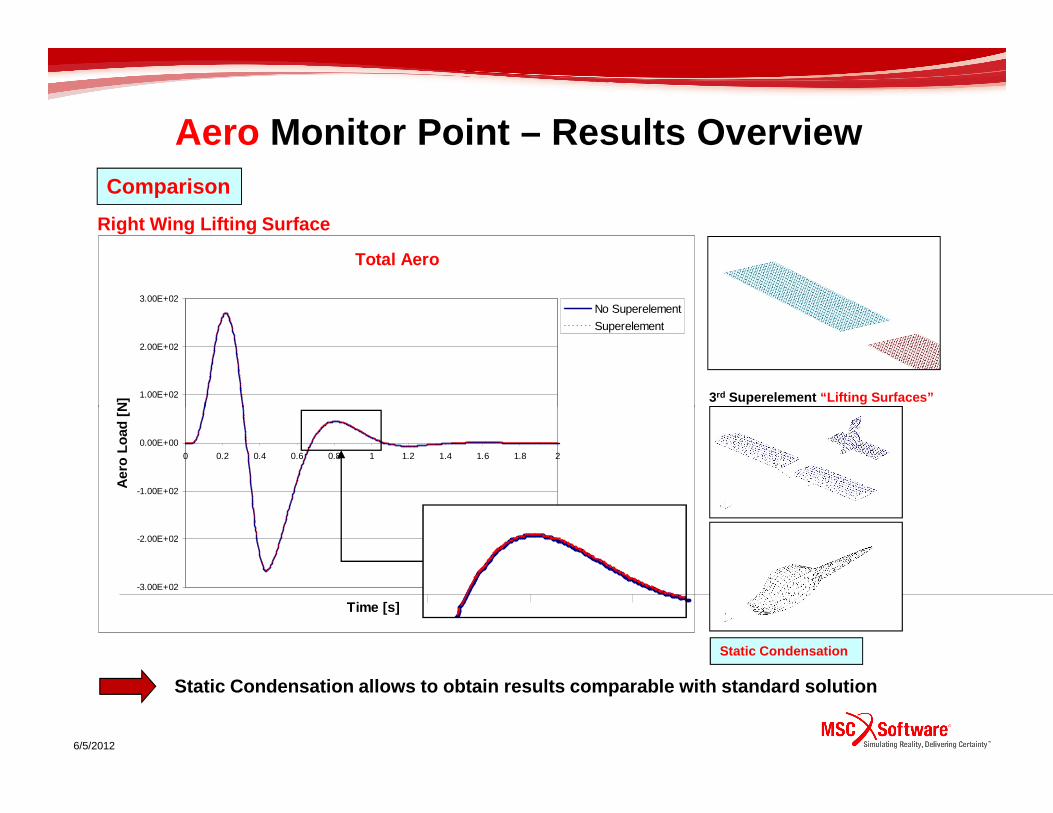
Aero Monitor Point – Results Overview
Total Aero
1.00E+02
2.00E+02
3.00E+02
Aer
o Lo
ad [
N]
No Superelement
Superelement
Right Wing Lifting Surface
Comparison
3rd Superelement “Lifting Surfaces”
6/5/2012
Static Condensation allows to obtain results compar able with standard solution
-3.00E+02
-2.00E+02
-1.00E+02
0.00E+00
0 0.2 0.4 0.6 0.8 1 1.2 1.4 1.6 1.8 2
Time [s]
Aer
o Lo
ad [
N]
Static Condensation 0.6 0.8 1

Sol146 - Remarks
1. Depending on the Superelement definition (SESET1 cards) Static
Reduction could not be the right approach for the aeroelastic system
identification
2. Component Mode Synthesis is the right approach to take into account
the dynamic contribution of the Superelement
3. All structural lifting surfaces can be condensed into Superelements3. All structural lifting surfaces can be condensed into Superelements
4. Structural Nodes specified in SET1 cards of the SPLINE cards can be
internal to Superelements
5. Structural monitor points cannot refer to Nodes internal to the
Superelement
6. To get all the external integrated load applied to a lifting surface, the
nodes defined in the SET1 card for splining must be all the same
external nodes which belong to that component
7. The aero monitor point can be defined wherever