sun zfs storage 7x20 appliance customer service manual - oracle
TRANSCRIPT

Sun ZFS Storage 7x20 Appliance CustomerService Manual
Part No: E26399December 2011 E26399–02

Copyright © 2009, 2011, Oracle and/or its affiliates. All rights reserved.
This software and related documentation are provided under a license agreement containing restrictions on use and disclosure and are protected by intellectualproperty laws. Except as expressly permitted in your license agreement or allowed by law, you may not use, copy, reproduce, translate, broadcast, modify, license,transmit, distribute, exhibit, perform, publish or display any part, in any form, or by any means. Reverse engineering, disassembly, or decompilation of this software,unless required by law for interoperability, is prohibited.
The information contained herein is subject to change without notice and is not warranted to be error-free. If you find any errors, please report them to us in writing.
If this is software or related documentation that is delivered to the U.S. Government or anyone licensing it on behalf of the U.S. Government, the following notice isapplicable:
U.S. GOVERNMENT RIGHTS
Programs, software, databases, and related documentation and technical data delivered to U.S. Government customers are "commercial computer software" or"commercial technical data" pursuant to the applicable Federal Acquisition Regulation and agency-specific supplemental regulations. As such, the use, duplication,disclosure, modification, and adaptation shall be subject to the restrictions and license terms set forth in the applicable Government contract, and, to the extentapplicable by the terms of the Government contract, the additional rights set forth in FAR 52.227-19, Commercial Computer Software License (December 2007).Oracle America, Inc., 500 Oracle Parkway, Redwood City, CA 94065.
This software or hardware is developed for general use in a variety of information management applications. It is not developed or intended for use in any inherentlydangerous applications, including applications that may create a risk of personal injury. If you use this software or hardware in dangerous applications, then you shallbe responsible to take all appropriate fail-safe, backup, redundancy, and other measures to ensure its safe use. Oracle Corporation and its affiliates disclaim anyliability for any damages caused by use of this software or hardware in dangerous applications.
Oracle and Java are registered trademarks of Oracle and/or its affiliates. Other names may be trademarks of their respective owners.
Intel and Intel Xeon are trademarks or registered trademarks of Intel Corporation. All SPARC trademarks are used under license and are trademarks or registeredtrademarks of SPARC International, Inc. AMD, Opteron, the AMD logo, and the AMD Opteron logo are trademarks or registered trademarks of Advanced MicroDevices. UNIX is a registered trademark of The Open Group.
This software or hardware and documentation may provide access to or information on content, products, and services from third parties. Oracle Corporation andits affiliates are not responsible for and expressly disclaim all warranties of any kind with respect to third-party content, products, and services. Oracle Corporationand its affiliates will not be responsible for any loss, costs, or damages incurred due to your access to or use of third-party content, products, or services.
Ce logiciel et la documentation qui l’accompagne sont protégés par les lois sur la propriété intellectuelle. Ils sont concédés sous licence et soumis à des restrictionsd’utilisation et de divulgation. Sauf disposition de votre contrat de licence ou de la loi, vous ne pouvez pas copier, reproduire, traduire, diffuser, modifier, breveter,transmettre, distribuer, exposer, exécuter, publier ou afficher le logiciel, même partiellement, sous quelque forme et par quelque procédé que ce soit. Par ailleurs, il estinterdit de procéder à toute ingénierie inverse du logiciel, de le désassembler ou de le décompiler, excepté à des fins d’interopérabilité avec des logiciels tiers ou tel queprescrit par la loi.
Les informations fournies dans ce document sont susceptibles de modification sans préavis. Par ailleurs, Oracle Corporation ne garantit pas qu’elles soient exemptesd’erreurs et vous invite, le cas échéant, à lui en faire part par écrit.
Si ce logiciel, ou la documentation qui l’accompagne, est concédé sous licence au Gouvernement des Etats-Unis, ou à toute entité qui délivre la licence de ce logicielou l’utilise pour le compte du Gouvernement des Etats-Unis, la notice suivante s’applique :
U.S. GOVERNMENT RIGHTS. Programs, software, databases, and related documentation and technical data delivered to U.S. Government customers are"commercial computer software" or "commercial technical data" pursuant to the applicable Federal Acquisition Regulation and agency-specific supplementalregulations. As such, the use, duplication, disclosure, modification, and adaptation shall be subject to the restrictions and license terms set forth in the applicableGovernment contract, and, to the extent applicable by the terms of the Government contract, the additional rights set forth in FAR 52.227-19, CommercialComputer Software License (December 2007). Oracle America, Inc., 500 Oracle Parkway, Redwood City, CA 94065.
Ce logiciel ou matériel a été développé pour un usage général dans le cadre d’applications de gestion des informations. Ce logiciel ou matériel n’est pas conçu ni n’estdestiné à être utilisé dans des applications à risque, notamment dans des applications pouvant causer des dommages corporels. Si vous utilisez ce logiciel ou matérieldans le cadre d’applications dangereuses, il est de votre responsabilité de prendre toutes les mesures de secours, de sauvegarde, de redondance et autres mesuresnécessaires à son utilisation dans des conditions optimales de sécurité. Oracle Corporation et ses affiliés déclinent toute responsabilité quant aux dommages causéspar l’utilisation de ce logiciel ou matériel pour ce type d’applications.
Oracle et Java sont des marques déposées d’Oracle Corporation et/ou de ses affiliés.Tout autre nom mentionné peut correspondre à des marques appartenant àd’autres propriétaires qu’Oracle.
AMD, Opteron, le logo AMD et le logo AMD Opteron sont des marques ou des marques déposées d’Advanced Micro Devices. Intel et Intel Xeon sont des marques oudes marques déposées d’Intel Corporation. Toutes les marques SPARC sont utilisées sous licence et sont des marques ou des marques déposées de SPARCInternational, Inc. UNIX est une marque déposée concédé sous license par X/Open Company, Ltd.
111216@25097
Contents
Preface .....................................................................................................................................................7
1 Introduction ...........................................................................................................................................9Overview ..................................................................................................................................................9
Introduction ....................................................................................................................................9Hardware .............................................................................................................................................. 12
Hardware View ............................................................................................................................. 13BUI ................................................................................................................................................. 13CLI ................................................................................................................................................. 19Tasks .............................................................................................................................................. 21
2 Hardware Maintenance ......................................................................................................................23Maintenance ........................................................................................................................................ 23
Introduction ................................................................................................................................. 237120 ....................................................................................................................................................... 24
7120 Hardware Overview ........................................................................................................... 24Chassis Overview ......................................................................................................................... 25Electrical Specifications ............................................................................................................... 27Internal Components .................................................................................................................. 27Standalone Controller Configurations ...................................................................................... 32Attached Storage .......................................................................................................................... 34
7320 ....................................................................................................................................................... 347320 Hardware Overview ........................................................................................................... 34Chassis Overview ......................................................................................................................... 347320 Replaceable Components .................................................................................................. 407320 Single and Cluster Controller Configurations ................................................................ 41
7420 ....................................................................................................................................................... 43
3
7420 Hardware Overview ........................................................................................................... 43Chassis Overview ......................................................................................................................... 44Internal Boards ............................................................................................................................. 46Components ................................................................................................................................. 467420 Standalone and Cluster Controller Configurations ....................................................... 50Attached Storage .......................................................................................................................... 52
7x20 ....................................................................................................................................................... 537x20 CRU Maintenance Procedures .......................................................................................... 53Prerequisites ................................................................................................................................. 53Safety Information ....................................................................................................................... 53Required Tools and Information ............................................................................................... 54Chassis Serial Number ................................................................................................................. 54Controller Replacement Tasks ................................................................................................... 54
SAS2 ...................................................................................................................................................... 80Sun Disk Shelf Overview ............................................................................................................. 80
Shelf ....................................................................................................................................................... 86Disk Shelf Maintenance Procedures .......................................................................................... 86Prerequisites ................................................................................................................................. 86Safety Information ....................................................................................................................... 86Electrostatic Discharge Precautions .......................................................................................... 87Tasks .............................................................................................................................................. 87
Faults ..................................................................................................................................................... 93Hardware Faults ........................................................................................................................... 93
HBA Expansion pt.1 ............................................................................................................................ 95Expanding from 2 to 3 HBAs ...................................................................................................... 95
HBA Expansion pt.2 .......................................................................................................................... 100Expanding from 3 to 4 HBAs .................................................................................................... 100
3 System Maintenance .........................................................................................................................105System ................................................................................................................................................. 105
Introduction ............................................................................................................................... 105System Disks ............................................................................................................................... 105Support Bundles ......................................................................................................................... 106Initial Setup ................................................................................................................................. 107Factory Reset ............................................................................................................................... 108
Contents
Sun ZFS Storage 7x20 Appliance Customer Service Manual • December 2011 E26399–024

Updates ............................................................................................................................................... 108System Updates .......................................................................................................................... 108
Passthrough x ..................................................................................................................................... 125Passthrough-x Deferred Update .............................................................................................. 125
User Quotas ........................................................................................................................................ 125User Quotas Deferred Update .................................................................................................. 125
COMSTAR ......................................................................................................................................... 126COMSTAR Deferred Update ................................................................................................... 126
Triple Parity RAID ............................................................................................................................ 126Triple-Parity RAID Deferred Update ...................................................................................... 126
Dedup ................................................................................................................................................. 127Data Deduplication Deferred Update ..................................................................................... 127
Replication ......................................................................................................................................... 127Replication Deferred Update .................................................................................................... 127
Received Properties ........................................................................................................................... 127Received Properties Deferred Update ..................................................................................... 127
Slim ZIL .............................................................................................................................................. 128Introduction ............................................................................................................................... 128
Snapshot Deletion ............................................................................................................................. 128Snapshot Deletion Deferred Update ....................................................................................... 128
Recursive Snapshots .......................................................................................................................... 128Recursive Snapshots Deferred Update .................................................................................... 128
Multi Replace ..................................................................................................................................... 129Multi Replace Deferred Update ................................................................................................ 129
RAIDZ Mirror ................................................................................................................................... 129RAIDZ/Mirror Deferred Update ............................................................................................. 129
Optional Child Dir ............................................................................................................................ 129Introduction ............................................................................................................................... 129
ConfigurationBackup ....................................................................................................................... 130Configuration Backup ............................................................................................................... 130
Problems ............................................................................................................................................. 135Problems ..................................................................................................................................... 135Active problems display ............................................................................................................ 135Repairing problems ................................................................................................................... 136Related features .......................................................................................................................... 136
Logs ..................................................................................................................................................... 136
Contents
5
Introduction ............................................................................................................................... 136BUI ............................................................................................................................................... 138CLI ............................................................................................................................................... 138
Glossary .............................................................................................................................................. 141
Index ................................................................................................................................................... 145
Contents
Sun ZFS Storage 7x20 Appliance Customer Service Manual • December 2011 E26399–026
Preface
The Sun ZFS Storage 7x20 Appliance Customer Service Manual contains hardware overviewsand maintenance procedures for Oracle's Sun ZFS Storage 7x20 series of NAS appliances.
This documentation is also available while using the Browser User Interface, accessible via theHelp button. The appliance documentation may be updated using the System Upgradeprocedure documented in the System Maintenance chapter of this book.
Who Should Use This BookThese notes are for users and system administrators who service and use the Sun ZFS Storage7x20 Appliances.
Related DocumentationRefer to the following documentation for installation instructions, hardware overviews, serviceprocedures and software update notes.
■ Installation Guide, Analytics Guide and Administration Guide (http://www.oracle.com/technetwork/documentation/)
Access to Oracle SupportOracle customers have access to electronic support through My Oracle Support. Forinformation, visit http://www.oracle.com/pls/topic/lookup?ctx=acc&id=info or visithttp://www.oracle.com/pls/topic/lookup?ctx=acc&id=trs if you are hearing impaired.
7

8
Introduction
Overview
IntroductionThe Sun ZFS Storage 7000 family of products provide efficient file and block data services toclients over a network, and a rich set of data services that can be applied to the data stored on thesystem.
Platforms■ 7120■ 7320■ 7420
Legacy platforms are documented in the 7110, 7210, 7310, 7410, J4400/J4500 sections of the SunStorage 7000 Unified Storage System Service Manual.
Expansion Storage■ Sun Disk Shelf
1C H A P T E R 1
9
ProtocolsSun ZFS Storage appliances include support for a variety of industry-standard client protocols,including:■ SMB■ NFS■ HTTP and HTTPS■ WebDAV■ iSCSI■ FC■ SRP■ iSER■ FTP■ SFTP
Key FeaturesSun ZFS Storage systems also include new technologies to deliver the best storageprice/performance and unprecedented observability of your workloads in production,including:■ Analytics, a system for dynamically observing the behavior of your system in real-time and
viewing data graphically■ The ZFS Hybrid Storage Pool, composed of optional Flash-memory devices for acceleration
of reads and writes, low-power, high-capacity disks, and DRAM memory, all managedtransparently as a single data hierarchy
Data ServicesTo manage the data that you export using these protocols, you can configure your Sun ZFSStorage system using the built-in collection of advanced data services, including:
LICENSE NOTICE: Remote Replication and Cloning may be evaluated free of charge,but each feature requires that an independent license be purchased separately for use inproduction. After the evaluation period, these features must either be licensed ordeactivated. Oracle reserves the right to audit for licensing compliance at any time. Fordetails, refer to the "Oracle Software License Agreement ("SLA") and Entitlement forHardware Systems with Integrated Software Options."
■ RAID-Z (RAID-5 and RAID-6), mirrored, and striped disk configurations■ Unlimited read-only and read-write snapshots, with snapshot schedules■ Data deduplication■ Built-in data compression■ Remote replication of data for disaster recovery■ Active-active clustering for high availability (7310, 7320, 7410, and 7420)
Overview
Sun ZFS Storage 7x20 Appliance Customer Service Manual • December 2011 E26399–0210
■ Thin provisioning of iSCSI LUNs■ Virus scanning and quarantine■ NDMP backup and restore
AvailabilityTo maximize the availability of your data in production, Sun ZFS Storage appliances include acomplete end-to-end architecture for data integrity, including redundancies at every level of thestack. Key features include:■ Predictive self-healing and diagnosis of all system hardware failures: CPUs, DRAM, I/O
cards, disks, fans, power supplies■ ZFS end-to-end data checksums of all data and metadata, protecting data throughout the
stack■ RAID-6 (double- and triple-parity) and optional RAID-6 across disk shelves■ Active-active clustering for high availability (7310, 7320, 7410, and 7420)■ Link aggregations and IP multipathing for network failure protection■ I/O Multipathing between the controller and disk shelves■ Integrated software restart of all system software services■ Phone-Home of telemetry for all software and hardware issues■ Lights-out Management of each system for remote power control and console access
Browser User Interface (BUI)
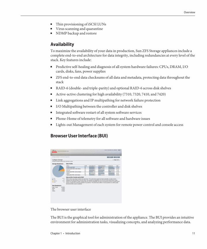
The browser user interface
The BUI is the graphical tool for administration of the appliance. The BUI provides an intuitiveenvironment for administration tasks, visualizing concepts, and analyzing performance data.
Overview
Chapter 1 • Introduction 11
The management software is designed to be fully featured and functional on a variety of webbrowsers.
Direct your browser to the system using either the IP address or host name you assigned to theNET-0 port during initial configuration as follows: https://ipaddress:215 orhttps://hostname:215. The login screen appears.
The online help linked in the top right of the BUI is context-sensitive. For every top-level andsecond-level screen in the BUI, the associated help page appears when you click the Helpbutton.
Command Line Interface (CLI)The CLI is designed to mirror the capabilities of the BUI, while also providing a powerfulscripting environment for performing repetitive tasks. The following sections describe details ofthe CLI. When navigating through the CLI, there are two principles to be aware of:
■ Tab completion is used extensively: if you are not sure what to type in any given context,pressing the Tab key will provide you with possible options. Throughout thedocumentation, pressing Tab is presented as the word "tab" in bold italics.
■ Help is always available: the help command provides context-specific help. Help on aparticular topic is available by specifying the topic as an argument to help, for example helpcommands. Available topics are displayed by tab-completing the help command, or by typinghelp topics.
You can combine these two principles, as follows:
dory:> help tab
builtins commands general help properties script
Hardware
Hardware
Sun ZFS Storage 7x20 Appliance Customer Service Manual • December 2011 E26399–0212
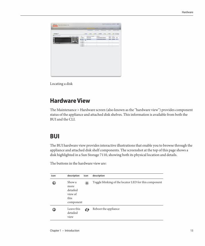
Locating a disk
Hardware ViewThe Maintenance > Hardware screen (also known as the "hardware view") provides componentstatus of the appliance and attached disk shelves. This information is available from both theBUI and the CLI.
BUIThe BUI hardware view provides interactive illustrations that enable you to browse through theappliance and attached disk shelf components. The screenshot at the top of this page shows adisk highlighted in a Sun Storage 7110, showing both its physical location and details.
The buttons in the hardware view are:
icon description icon description
Show amoredetailedview ofthiscomponent
Toggle blinking of the locator LED for this component
Leave thisdetailedview
Reboot the appliance
Hardware
Chapter 1 • Introduction 13

icon description icon description
Click formoredetails
Power off the appliance
Hardwarecomponentis ok(green)
Offline disk
Hardwarecomponentis notpresent(grey)
Port active
Hardwarecomponentis faulted(amber)
Port inactive
System OverviewThe main hardware page lists the system chassis, a summary of its contents, and any attacheddisk shelves (on supported systems). This provides an overview of the hardware present on thesystem, as well as controls to reset or power off the system.
System Chassis
The primary system chassis is shown on the top half of the view. At the top left, click the toget more detail about the chassis. The indicator notes if there are any faulted componentswithin the chassis, and the name of the chassis. The chassis name is initially set to the appliancename during installation. To change the chassis name, use the entry field on the Configuration> Services > System Identity screen.
At the top right of the system chassis is the control to light the locate LED, reboot theappliance, and power off the chassis.
A thumbnail of the controller is presented at left. Clicking on the thumbnail or the "ShowDetails" link takes you to a detailed view of the chassis, and is identical to clicking on the rightpointing arrow at the top left of the view.
The following information is presented in a summary view:
Property Description
Manufacturer Manufacturer of the system
Hardware
Sun ZFS Storage 7x20 Appliance Customer Service Manual • December 2011 E26399–0214
Property Description
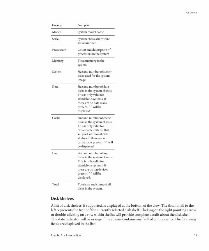
Model System model name
Serial System chassis hardwareserial number
Processors Count and description ofprocessors in the system
Memory Total memory in thesystem
System Size and number of systemdisks used for the systemimage
Data Size and number of datadisks in the system chassis.This is only valid forstandalone systems. Ifthere are no data diskspresent, "-" will bedisplayed.
Cache Size and number of cachedisks in the system chassis.This is only valid forexpandable systems thatsupport additional diskshelves. If there are nocache disks present, "-" willbe displayed.
Log Size and number of logdisks in the system chassis.This is only valid forstandalone systems. Ifthere are no log devicespresent, "-" will bedisplayed.
Total Total size and count of alldisks in the system.
Disk ShelvesA list of disk shelves, if supported, is displayed at the bottom of the view. The thumbnail to theleft represents the front of the currently selected disk shelf. Clicking on the right pointing arrowor double-clicking on a row within the list will provide complete details about the disk shelf.The state indicator will be orange if the chassis contains any faulted components. The followingfields are displayed in the list:
Hardware
Chapter 1 • Introduction 15
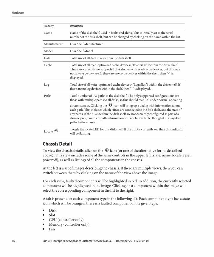
Property Description
Name Name of the disk shelf, used in faults and alerts. This is initially set to the serialnumber of the disk shelf, but can be changed by clicking on the name within the list.
Manufacturer Disk Shelf Manufacturer
Model Disk Shelf Model
Data Total size of all data disks within the disk shelf.
Cache Total size of all read-optimized cache devices ("Readzillas") within the drive shelf.There are currently no supported disk shelves with read cache devices, but this maynot always be the case. If there are no cache devices within the shelf, then "-" isdisplayed.
Log Total size of all write-optimized cache devices ("Logzillas") within the drive shelf. Ifthere are no log devices within the shelf, then "-" is displayed.
Paths Total number of I/O paths to the disk shelf. The only supported configurations arethose with multiple paths to all disks, so this should read "2" under normal operating
circumstances. Clicking the icon will bring up a dialog with information abouteach path. This includes which HBAs are connected to the disk shelf, and the state ofany paths. If the disks within the disk shelf are not currently configured as part of astorage pool, complete path information will not be available, though it displays twopaths to the chassis.
Locate Toggle the locate LED for this disk shelf. If the LED is currently on, then this indicatorwill be flashing.
Chassis DetailTo view the chassis details, click on the icon (or one of the alternative forms describedabove). This view includes some of the same controls in the upper left (state, name, locate, reset,poweroff), as well as listings of all the components in the chassis.
At the left is a set of images describing the chassis. If there are multiple views, then you canswitch between them by clicking on the name of the view above the image.
For each view, faulted components will be highlighted in red. In addition, the currently selectedcomponent will be highlighted in the image. Clicking on a component within the image willselect the corresponding component in the list to the right.
A tab is present for each component type in the following list. Each component type has a stateicon which will be orange if there is a faulted component of the given type.■ Disk■ Slot■ CPU (controller only)■ Memory (controller only)■ Fan
Hardware
Sun ZFS Storage 7x20 Appliance Customer Service Manual • December 2011 E26399–0216
■ Power supply (PSU)■ Service processor (SP) (controller only)
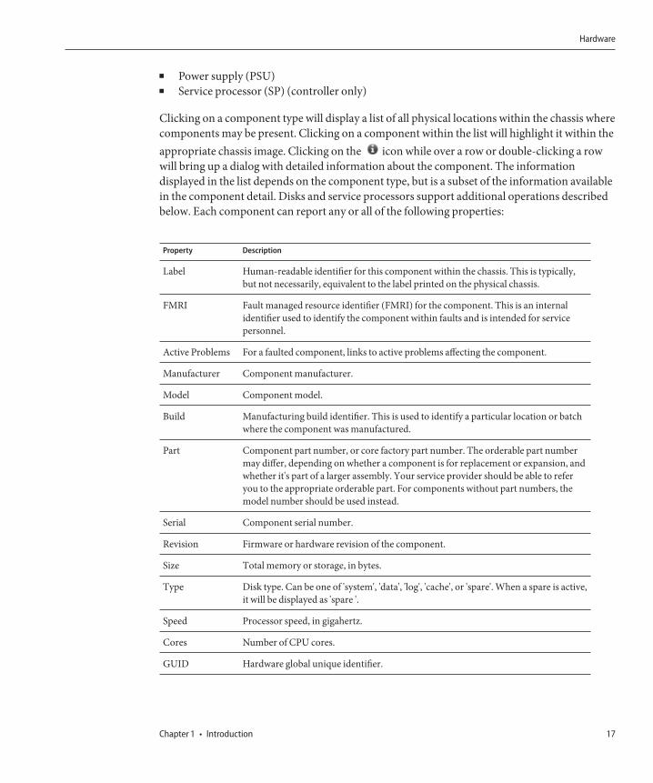
Clicking on a component type will display a list of all physical locations within the chassis wherecomponents may be present. Clicking on a component within the list will highlight it within theappropriate chassis image. Clicking on the icon while over a row or double-clicking a rowwill bring up a dialog with detailed information about the component. The informationdisplayed in the list depends on the component type, but is a subset of the information availablein the component detail. Disks and service processors support additional operations describedbelow. Each component can report any or all of the following properties:
Property Description
Label Human-readable identifier for this component within the chassis. This is typically,but not necessarily, equivalent to the label printed on the physical chassis.
FMRI Fault managed resource identifier (FMRI) for the component. This is an internalidentifier used to identify the component within faults and is intended for servicepersonnel.
Active Problems For a faulted component, links to active problems affecting the component.
Manufacturer Component manufacturer.
Model Component model.
Build Manufacturing build identifier. This is used to identify a particular location or batchwhere the component was manufactured.
Part Component part number, or core factory part number. The orderable part numbermay differ, depending on whether a component is for replacement or expansion, andwhether it's part of a larger assembly. Your service provider should be able to referyou to the appropriate orderable part. For components without part numbers, themodel number should be used instead.
Serial Component serial number.
Revision Firmware or hardware revision of the component.
Size Total memory or storage, in bytes.
Type Disk type. Can be one of 'system', 'data', 'log', 'cache', or 'spare'. When a spare is active,it will be displayed as 'spare '.
Speed Processor speed, in gigahertz.
Cores Number of CPU cores.
GUID Hardware global unique identifier.
Hardware
Chapter 1 • Introduction 17
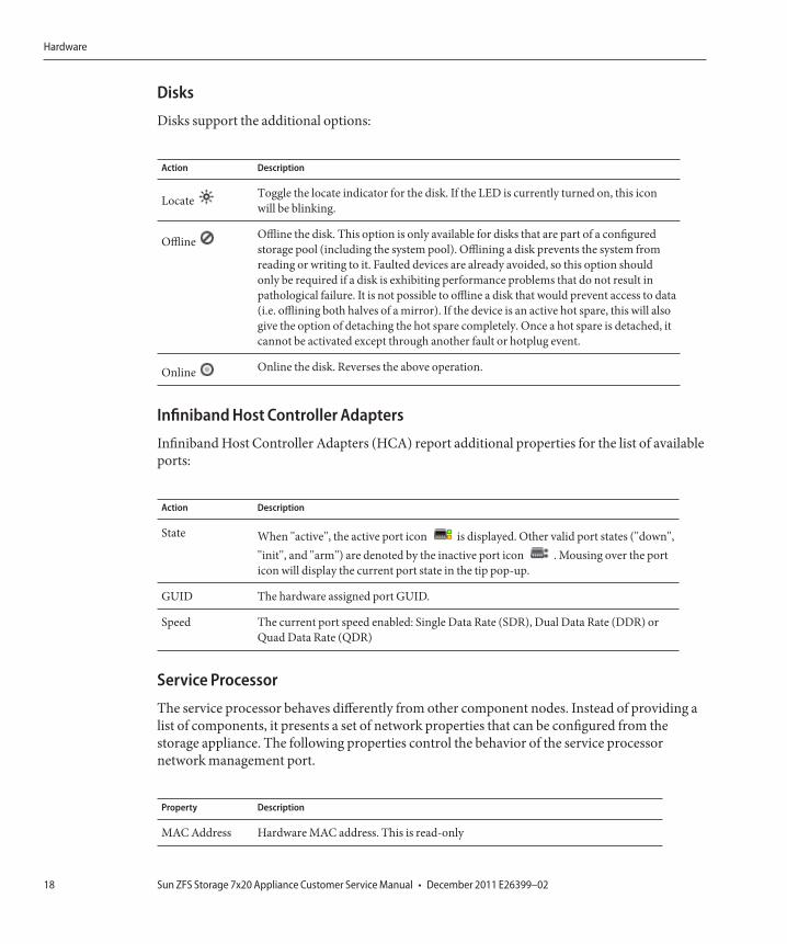
Disks
Disks support the additional options:
Action Description
Locate Toggle the locate indicator for the disk. If the LED is currently turned on, this iconwill be blinking.
Offline Offline the disk. This option is only available for disks that are part of a configuredstorage pool (including the system pool). Offlining a disk prevents the system fromreading or writing to it. Faulted devices are already avoided, so this option shouldonly be required if a disk is exhibiting performance problems that do not result inpathological failure. It is not possible to offline a disk that would prevent access to data(i.e. offlining both halves of a mirror). If the device is an active hot spare, this will alsogive the option of detaching the hot spare completely. Once a hot spare is detached, itcannot be activated except through another fault or hotplug event.
Online Online the disk. Reverses the above operation.
Infiniband Host Controller Adapters
Infiniband Host Controller Adapters (HCA) report additional properties for the list of availableports:
Action Description
State When "active", the active port icon is displayed. Other valid port states ("down","init", and "arm") are denoted by the inactive port icon . Mousing over the porticon will display the current port state in the tip pop-up.
GUID The hardware assigned port GUID.
Speed The current port speed enabled: Single Data Rate (SDR), Dual Data Rate (DDR) orQuad Data Rate (QDR)
Service Processor
The service processor behaves differently from other component nodes. Instead of providing alist of components, it presents a set of network properties that can be configured from thestorage appliance. The following properties control the behavior of the service processornetwork management port.
Property Description
MAC Address Hardware MAC address. This is read-only
Hardware
Sun ZFS Storage 7x20 Appliance Customer Service Manual • December 2011 E26399–0218
Property Description
IP AddressSource
Either 'DHCP' or 'Static'. Controls whether DHCP should be used on the interface.
IP Address IPv4 Address, when using static IP configuration. IPv6 is not supported.
Subnet Dotted decimal subnet, when using static IP configuration.
Default Gateway IPv4 default gateway address.
Changing multiple values in conflicting ways (such as changing static IP assignments while inDHCP mode) has undefined behavior.
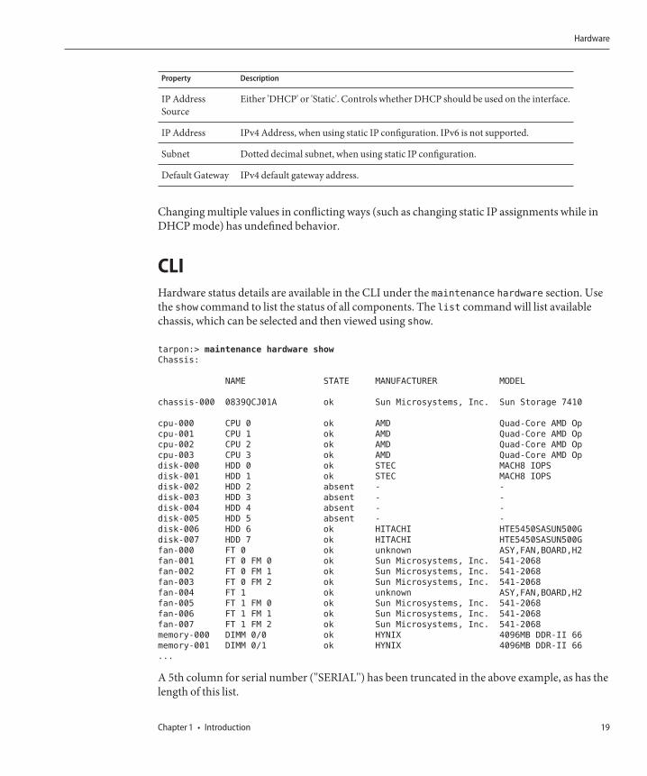
CLIHardware status details are available in the CLI under the maintenance hardware section. Usethe show command to list the status of all components. The list command will list availablechassis, which can be selected and then viewed using show.
tarpon:> maintenance hardware show
Chassis:
NAME STATE MANUFACTURER MODEL
chassis-000 0839QCJ01A ok Sun Microsystems, Inc. Sun Storage 7410
cpu-000 CPU 0 ok AMD Quad-Core AMD Op
cpu-001 CPU 1 ok AMD Quad-Core AMD Op
cpu-002 CPU 2 ok AMD Quad-Core AMD Op
cpu-003 CPU 3 ok AMD Quad-Core AMD Op
disk-000 HDD 0 ok STEC MACH8 IOPS
disk-001 HDD 1 ok STEC MACH8 IOPS
disk-002 HDD 2 absent - -
disk-003 HDD 3 absent - -
disk-004 HDD 4 absent - -
disk-005 HDD 5 absent - -
disk-006 HDD 6 ok HITACHI HTE5450SASUN500G
disk-007 HDD 7 ok HITACHI HTE5450SASUN500G
fan-000 FT 0 ok unknown ASY,FAN,BOARD,H2
fan-001 FT 0 FM 0 ok Sun Microsystems, Inc. 541-2068
fan-002 FT 0 FM 1 ok Sun Microsystems, Inc. 541-2068
fan-003 FT 0 FM 2 ok Sun Microsystems, Inc. 541-2068
fan-004 FT 1 ok unknown ASY,FAN,BOARD,H2
fan-005 FT 1 FM 0 ok Sun Microsystems, Inc. 541-2068
fan-006 FT 1 FM 1 ok Sun Microsystems, Inc. 541-2068
fan-007 FT 1 FM 2 ok Sun Microsystems, Inc. 541-2068
memory-000 DIMM 0/0 ok HYNIX 4096MB DDR-II 66
memory-001 DIMM 0/1 ok HYNIX 4096MB DDR-II 66
...
A 5th column for serial number ("SERIAL") has been truncated in the above example, as has thelength of this list.
Hardware
Chapter 1 • Introduction 19
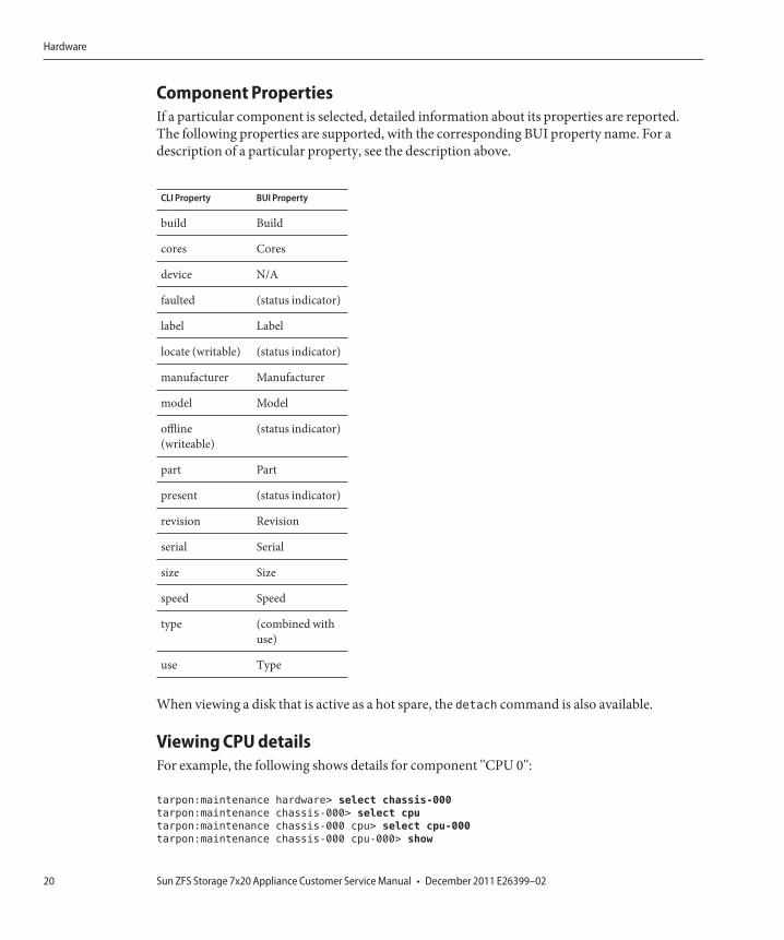
Component PropertiesIf a particular component is selected, detailed information about its properties are reported.The following properties are supported, with the corresponding BUI property name. For adescription of a particular property, see the description above.
CLI Property BUI Property
build Build
cores Cores
device N/A
faulted (status indicator)
label Label
locate (writable) (status indicator)
manufacturer Manufacturer
model Model
offline(writeable)
(status indicator)
part Part
present (status indicator)
revision Revision
serial Serial
size Size
speed Speed
type (combined withuse)
use Type
When viewing a disk that is active as a hot spare, the detach command is also available.
Viewing CPU detailsFor example, the following shows details for component "CPU 0":
tarpon:maintenance hardware> select chassis-000
tarpon:maintenance chassis-000> select cpu
tarpon:maintenance chassis-000 cpu> select cpu-000
tarpon:maintenance chassis-000 cpu-000> show
Hardware
Sun ZFS Storage 7x20 Appliance Customer Service Manual • December 2011 E26399–0220
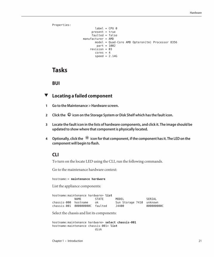
Properties:
label = CPU 0
present = true
faulted = false
manufacturer = AMD
model = Quad-Core AMD Opteron(tm) Processor 8356
part = 1002
revision = 03
cores = 4
speed = 2.14G
Tasks
BUI
▼ Locating a failed component
Go to the Maintenance > Hardware screen.
Click the icon on the Storage System or Disk Shelf which has the fault icon.
Locate the fault icon in the lists of hardware components, and click it. The image should beupdated to show where that component is physically located.
Optionally, click the icon for that component, if the component has it. The LED on thecomponent will begin to flash.
CLITo turn on the locate LED using the CLI, run the following commands.
Go to the maintenance hardware context:
hostname:> maintenance hardware
List the appliance components:
hostname:maintenance hardware> list
NAME STATE MODEL SERIAL
chassis-000 hostname ok Sun Storage 7410 unknown
chassis-001 000000000C faulted J4400 000000000C
Select the chassis and list its components:
hostname:maintenance hardware> select chassis-001
hostname:maintenance chassis-001> list
disk
1
2
3
4
Hardware
Chapter 1 • Introduction 21
fan
psu
slot
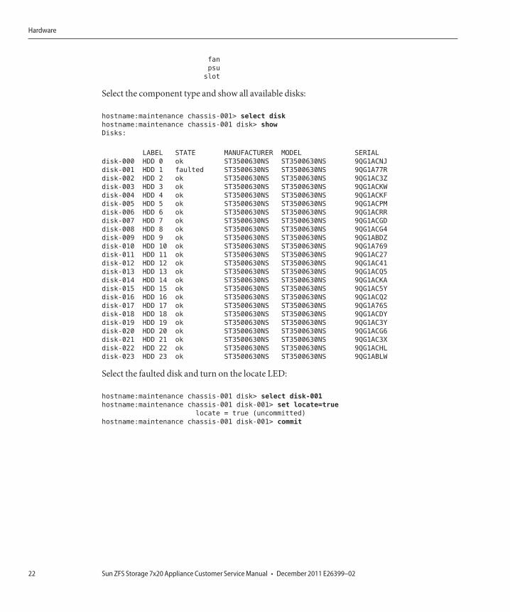
Select the component type and show all available disks:
hostname:maintenance chassis-001> select disk
hostname:maintenance chassis-001 disk> show
Disks:
LABEL STATE MANUFACTURER MODEL SERIAL
disk-000 HDD 0 ok ST3500630NS ST3500630NS 9QG1ACNJ
disk-001 HDD 1 faulted ST3500630NS ST3500630NS 9QG1A77R
disk-002 HDD 2 ok ST3500630NS ST3500630NS 9QG1AC3Z
disk-003 HDD 3 ok ST3500630NS ST3500630NS 9QG1ACKW
disk-004 HDD 4 ok ST3500630NS ST3500630NS 9QG1ACKF
disk-005 HDD 5 ok ST3500630NS ST3500630NS 9QG1ACPM
disk-006 HDD 6 ok ST3500630NS ST3500630NS 9QG1ACRR
disk-007 HDD 7 ok ST3500630NS ST3500630NS 9QG1ACGD
disk-008 HDD 8 ok ST3500630NS ST3500630NS 9QG1ACG4
disk-009 HDD 9 ok ST3500630NS ST3500630NS 9QG1ABDZ
disk-010 HDD 10 ok ST3500630NS ST3500630NS 9QG1A769
disk-011 HDD 11 ok ST3500630NS ST3500630NS 9QG1AC27
disk-012 HDD 12 ok ST3500630NS ST3500630NS 9QG1AC41
disk-013 HDD 13 ok ST3500630NS ST3500630NS 9QG1ACQ5
disk-014 HDD 14 ok ST3500630NS ST3500630NS 9QG1ACKA
disk-015 HDD 15 ok ST3500630NS ST3500630NS 9QG1AC5Y
disk-016 HDD 16 ok ST3500630NS ST3500630NS 9QG1ACQ2
disk-017 HDD 17 ok ST3500630NS ST3500630NS 9QG1A76S
disk-018 HDD 18 ok ST3500630NS ST3500630NS 9QG1ACDY
disk-019 HDD 19 ok ST3500630NS ST3500630NS 9QG1AC3Y
disk-020 HDD 20 ok ST3500630NS ST3500630NS 9QG1ACG6
disk-021 HDD 21 ok ST3500630NS ST3500630NS 9QG1AC3X
disk-022 HDD 22 ok ST3500630NS ST3500630NS 9QG1ACHL
disk-023 HDD 23 ok ST3500630NS ST3500630NS 9QG1ABLW
Select the faulted disk and turn on the locate LED:
hostname:maintenance chassis-001 disk> select disk-001
hostname:maintenance chassis-001 disk-001> set locate=true
locate = true (uncommitted)
hostname:maintenance chassis-001 disk-001> commit
Hardware
Sun ZFS Storage 7x20 Appliance Customer Service Manual • December 2011 E26399–0222
Hardware Maintenance
Maintenance
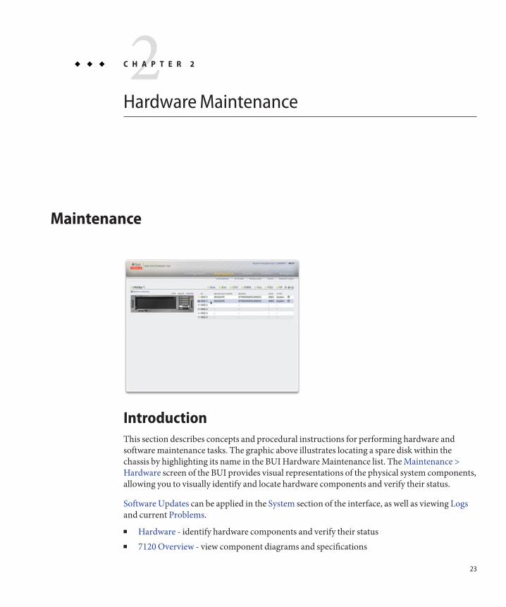
IntroductionThis section describes concepts and procedural instructions for performing hardware andsoftware maintenance tasks. The graphic above illustrates locating a spare disk within thechassis by highlighting its name in the BUI Hardware Maintenance list. The Maintenance >Hardware screen of the BUI provides visual representations of the physical system components,allowing you to visually identify and locate hardware components and verify their status.
Software Updates can be applied in the System section of the interface, as well as viewing Logsand current Problems.
■ Hardware - identify hardware components and verify their status■ 7120 Overview - view component diagrams and specifications
2C H A P T E R 2
23

■ 7320 Overview - view component diagrams, specifications, and cluster options■ 7420 Overview - view component diagrams, specifications, and cluster options■ 7120, 7320, 7420 Maintenance Procedures - replace controller or cabinet drives, fans, power
supplies, RAM, cards, risers, and batteries■ Disk Shelf Overview - view component diagrams and specifications■ Disk Shelf Maintenance Procedures - replace disk shelf components■ Hardware Faults - Connect to ILOM to diagnose hardware faults■ Expanding from 2 to 3 HBAs■ Expanding from 3 to 4 HBAs■ 7110 Overview■ 7210 Overview■ 7310 Overview■ 7410 Overview■ 7x10 Maintenance Procedures■ J4400/J4500 Overview
■ System - view system disks, manage support bundles■ Updates - manage appliance software updates■ Configuration Backup - backup and restore appliance configuration■ Problems - view current problems■ Logs - view appliance logs■ Workflows - manage and execute workflows
7120
7120 Hardware OverviewUse the information in this section as a preparation reference for servicing replaceablecomponents of the 7120 system.
Refer to the following for procedural instructions:
■ Controller Tasks - replace system controller components■ Disk Shelf Tasks - replace disk shelf components
7120
Sun ZFS Storage 7x20 Appliance Customer Service Manual • December 2011 E26399–0224
Chassis OverviewThe Sun ZFS Storage 7120 is an enterprise-class two-socket rackmount x64 system powered bythe Intel Xeon processor. It packs high performance and room for growth with four PCIe slotsand 18 DIMM slots into a compact 2U footprint. Refer to the http://www.oracle.com/us/products/servers-storage/storage/unified-storage/index.html (http://www.oracle.com/us/products/servers-storage/storage/unified-storage/index.html) for the mostrecent component specification.
Refer to the Implementing Fibre Channel SAN Boot with Oracle's Sun ZFS Storage Appliancewhitepaper at http://www.oracle.com/technetwork/articles/servers-storage-admin/fbsanboot-365291.html (http://www.oracle.com/technetwork/articles/servers-storage-admin/fbsanboot-365291.html) for details onFC SAN boot solutions using the Sun ZFS Storage 7120 Appliance.
The 7120 is a standalone controller that consists of an internal SAS-2 HBA providing disk shelfexpansion, write flash acceleration, and 11 x 300GB 15K, 600GB 15K, 1TB 7.2K, 2TB 7.2K, or3TB 7.2K hard drive storage. The SAS-2 storage fabric supports greater number of targets,greater bandwidth, higher reliability and bigger scale.
The 2U chassis form factor dimensions are as follows:
Dimension Measurement Dimension Measurement
Height 87.6 mm/3.45 in Depth 765.25 mm/30.13 in
Width 436.8 mm/17.2 in Weight 29.54 kg/65 lb
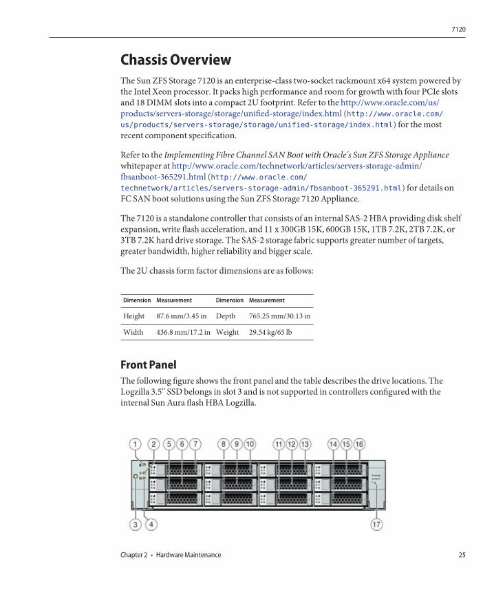
Front PanelThe following figure shows the front panel and the table describes the drive locations. TheLogzilla 3.5" SSD belongs in slot 3 and is not supported in controllers configured with theinternal Sun Aura flash HBA Logzilla.
7120
Chapter 2 • Hardware Maintenance 25

Figure Legend
1 Locator LED/button(white)
7 HDD 2 13 HDD 8
2 Service Action RequiredLED (amber)
8 HDD or SSD 3 14 HDD 9
3 Power button 9 HDD 4 15 HDD 10
4 Power/OK LED (green) 10 HDD 5 16 HDD 11
5 HDD 0 11 HDD 6 17 Drive map
6 HDD 1 12 HDD 7
Rear PanelThe following figure shows the rear panel. Note that optional Sun Dual Port 40Gb/sec 4xInfiniband QDR HCAdapter PCIe cards (375-3606-01) may be located in slots 1, 2, or 3. Notethat 375-3606-01 HCA expansion cards are not supported in the 10Gb network configurations.
Figure Legend
1 Power Supply Unit 1 6 PCIe 4 11 Network Management port
2 Power Supply Unit 0 7 Boot HDD 1 12 Gbit Ethernet ports NET 0, 1, 2, 3
3 PCIe 0 8 Boot HDD 0 13 USB 2.0 ports (0, 1)
4 PCIe 3 9 Rear Panel System Status LEDs 14 HD15 Video port
5 PCIe 1 10 Serial Management port
The serial management connector (SER MGT) is an RJ-45 port and provides a terminal
connection to the SP console.
7120
Sun ZFS Storage 7x20 Appliance Customer Service Manual • December 2011 E26399–0226
The network management connector (NET MGT) is an RJ-45 port and provides an alternate
terminal interface to the SP console.
There are four RJ-45 Gigabit Ethernet ports (NET0, NET1, NET2, NET3) located on themotherboard that operate at 10/100/1000 Mbit/sec. These network interfaces must beconfigured before use.
Electrical SpecificationsThe following list shows the electrical specifications for the 7120. Note that the powerdissipation numbers listed are the maximum rated power numbers for the power supply. Thenumbers are not a rating of the actual power consumption of the appliance.
Connectors
■ Two C13 connectors which work on 110-220v outlets
Input
■ Nominal frequencies: 50/60Hz■ Nominal voltage range: 100-120/200-240 VAC■ Maximum current AC RMS: 13.8A @ 100 VAC■ AC operating range: 90-264 VAC
Output
■ 3.3 VDC STBY: 3.0A■ +12 VDC: 86.7A
Power dissipation
■ Max power consumption: 1235.3 W■ Max heat output: 4212 BTU/hr■ Volt-Ampere rating: 1261 VA @ 240 VAC, 0.98P.F.
Internal ComponentsThe chassis has the following boards installed. Field-replaceable units (FRU) should only bereplaced by trained Oracle service technicians.
■ PCIe Risers - Each riser supports two PCIe cards that are customer-replaceable. There aretwo risers per system, each attached to the rear of the motherboard.
7120
Chapter 2 • Hardware Maintenance 27
■ Motherboard - The motherboard is a FRU and includes CPU modules, slots for 18 DIMMs,memory control subsystems, and the service processor (SP) subsystem. The SP subsystemcontrols the host power and monitors host system events (power and environmental). TheSP controller draws power from the host's 3.3V standby supply rail, which is availablewhenever the system is receiving AC input power, even when the system is turned off.
■ Power Distribution Board - The power distribution board is a FRU and distributes main12V power from the power supplies to the rest of the storage controller. It is directlyconnected to the Connector Break Out Board, and to the motherboard through a bus barand ribbon cable. It also supports a top cover interlock kill switch. The power suppliesconnect directly to the power distribution board.
■ Connector Break Out Board - The Connector Break Out Board is FRU and serves as theinterconnect between the power distribution board and the fan power boards, storage drivebackplane, and I/O board. It also contains the top-cover interlock "kill" switch.
■ Fan Power Boards - The two fan power boards are FRUs and carry power to the system fanmodules. In addition, they contain fan module status LEDs and transfer I2C data for the fanmodules.
■ Storage Drive Backplane - The storage drive backplane is a FRU and includes theconnectors for the storage drives, as well as the interconnect for the I/O board, Power andLocator buttons, and system/component status LEDs. The system has a 12-disk backplane.Each drive has an LED indicator for Power/Activity, Fault, and Locate.
7120
Sun ZFS Storage 7x20 Appliance Customer Service Manual • December 2011 E26399–0228

I/O ComponentsThe I/O components of the 7120 system are shown in the following figure and described in the
table.
Figure Legend
1 Top Cover 3 Hard Disk Drives
2 Right Control Panel Light Pipe Assembly 4 Left Control Panel Light Pipe Assembly
7120
Chapter 2 • Hardware Maintenance 29
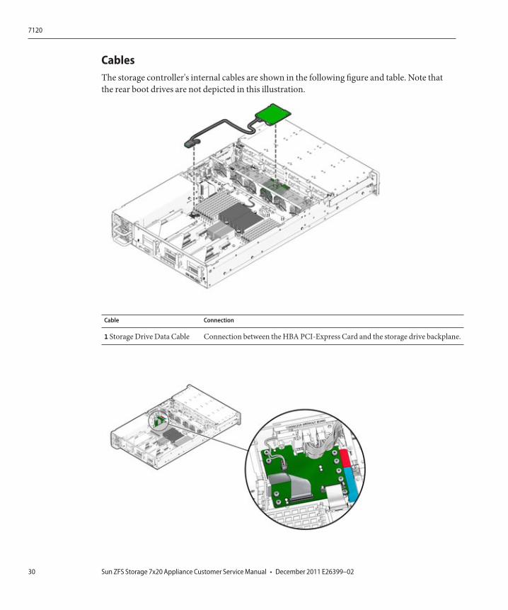
CablesThe storage controller's internal cables are shown in the following figure and table. Note thatthe rear boot drives are not depicted in this illustration.
Cable Connection
1 Storage Drive Data Cable Connection between the HBA PCI-Express Card and the storage drive backplane.
7120
Sun ZFS Storage 7x20 Appliance Customer Service Manual • December 2011 E26399–0230
Cable Connection
2 Ribbon cable Connection is between the power distribution board and the motherboard.
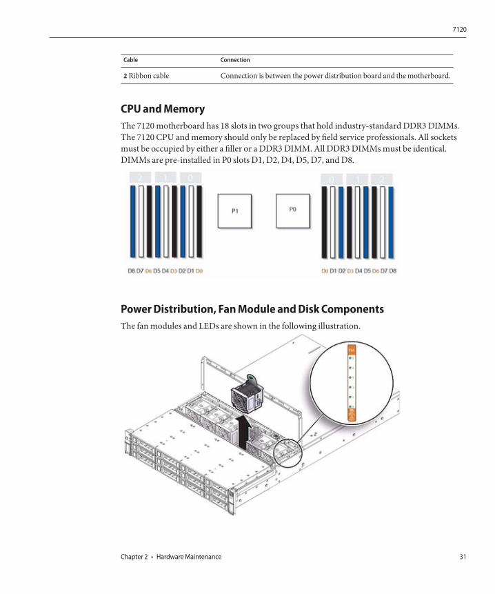
CPU and MemoryThe 7120 motherboard has 18 slots in two groups that hold industry-standard DDR3 DIMMs.The 7120 CPU and memory should only be replaced by field service professionals. All socketsmust be occupied by either a filler or a DDR3 DIMM. All DDR3 DIMMs must be identical.DIMMs are pre-installed in P0 slots D1, D2, D4, D5, D7, and D8.
Power Distribution, Fan Module and Disk ComponentsThe fan modules and LEDs are shown in the following illustration.
7120
Chapter 2 • Hardware Maintenance 31
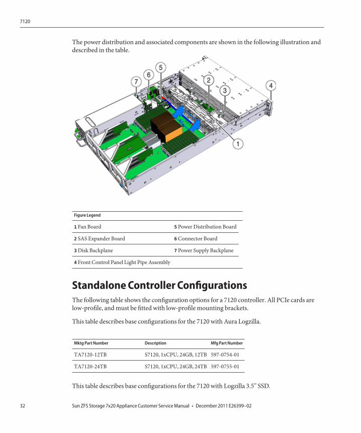
The power distribution and associated components are shown in the following illustration anddescribed in the table.
Figure Legend
1 Fan Board 5 Power Distribution Board
2 SAS Expander Board 6 Connector Board
3 Disk Backplane 7 Power Supply Backplane
4 Front Control Panel Light Pipe Assembly
Standalone Controller ConfigurationsThe following table shows the configuration options for a 7120 controller. All PCIe cards arelow-profile, and must be fitted with low-profile mounting brackets.
This table describes base configurations for the 7120 with Aura Logzilla.
Mktg Part Number Description Mfg Part Number
TA7120-12TB S7120, 1xCPU, 24GB, 12TB 597-0754-01
TA7120-24TB S7120, 1xCPU, 24GB, 24TB 597-0755-01
This table describes base configurations for the 7120 with Logzilla 3.5" SSD.
7120
Sun ZFS Storage 7x20 Appliance Customer Service Manual • December 2011 E26399–0232
Mktg Part Number Description Mfg Part Number
7101282 S7120, 1xCPU, 24GB, 3.3TB 7014523
7101284 S7120, 1xCPU, 24GB, 6.6TB 7014525
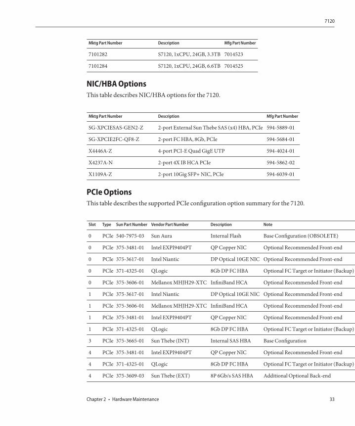
NIC/HBA OptionsThis table describes NIC/HBA options for the 7120.
Mktg Part Number Description Mfg Part Number
SG-XPCIESAS-GEN2-Z 2-port External Sun Thebe SAS (x4) HBA, PCIe 594-5889-01
SG-XPCIE2FC-QF8-Z 2-port FC HBA, 8Gb, PCIe 594-5684-01
X4446A-Z 4-port PCI-E Quad GigE UTP 594-4024-01
X4237A-N 2-port 4X IB HCA PCIe 594-5862-02
X1109A-Z 2-port 10Gig SFP+ NIC, PCIe 594-6039-01
PCIe OptionsThis table describes the supported PCIe configuration option summary for the 7120.
Slot Type Sun Part Number Vendor Part Number Description Note
0 PCIe 540-7975-03 Sun Aura Internal Flash Base Configuration (OBSOLETE)
0 PCIe 375-3481-01 Intel EXPI9404PT QP Copper NIC Optional Recommended Front-end
0 PCIe 375-3617-01 Intel Niantic DP Optical 10GE NIC Optional Recommended Front-end
0 PCIe 371-4325-01 QLogic 8Gb DP FC HBA Optional FC Target or Initiator (Backup)
0 PCIe 375-3606-01 Mellanox MHJH29-XTC InfiniBand HCA Optional Recommended Front-end
1 PCIe 375-3617-01 Intel Niantic DP Optical 10GE NIC Optional Recommended Front-end
1 PCIe 375-3606-01 Mellanox MHJH29-XTC InfiniBand HCA Optional Recommended Front-end
1 PCIe 375-3481-01 Intel EXPI9404PT QP Copper NIC Optional Recommended Front-end
1 PCIe 371-4325-01 QLogic 8Gb DP FC HBA Optional FC Target or Initiator (Backup)
3 PCIe 375-3665-01 Sun Thebe (INT) Internal SAS HBA Base Configuration
4 PCIe 375-3481-01 Intel EXPI9404PT QP Copper NIC Optional Recommended Front-end
4 PCIe 371-4325-01 QLogic 8Gb DP FC HBA Optional FC Target or Initiator (Backup)
4 PCIe 375-3609-03 Sun Thebe (EXT) 8P 6Gb/s SAS HBA Additional Optional Back-end
7120
Chapter 2 • Hardware Maintenance 33
Attached StorageThe 7120 standalone configurations allow a single chain of 1 or 2 Sun Disk Shelves.Write-optimized (Logzilla) SSDs are not supported in the expansion storage for the 7120. Thedisk shelves must be fully populated with 24 HDDs. Half-populated shelf configurations are notsupported.
7320
7320 Hardware OverviewUse the information in this section as a preparation and reference for servicing replaceablecomponents of the 7320 system. Refer to the following for procedural instructions:
■ Controller Tasks - replace storage controller components■ Disk Shelf Tasks - replace disk shelf components
Chassis OverviewThe Sun ZFS Storage 7320 System consists of either a single storage controller, or two storagecontrollers in a high availability cluster configuration, and one to four Sun Disk Shelves.
The 7320 controller base configuration includes two CPUs, built-in 4 x 1Gb/s front-end GigEports, redundant power supplies, NIC options for expanded front-end support, tape backup,Infiniband, and dual port SAS HBA for storage expansion.
The CPUs are Intel Xeon 5600 series, 2.40GHz, 80W, 4 core processors. Standard memoryconfiguration is 24GB, 3 x 4GB DDR3-1333 DR DIMMs and may be upgraded to 48GB using6x4GB DDR3-1333 DR DIMMs per CPU or to 72GB using 9x4GB DDR3 DR DIMMs per CPU.The clustered configuration simply uses two servers and a cluster card in each server for aheartbeat connection between them.
All user-accessible storage is provided by one to four Sun Disk shelves external to the server(s).The RAID function is done by the software. Solid State 18GB SAS-1 drives (7320 SAS-2) whichare used for high-performance write cache known as LogZilla or ZFS intent log (ZIL) devices,are in place of one to four of the 24 drives in the Disk Shelf, the remaining 20 drives are availablefor storage.
Refer to the http://www.oracle.com/us/products/servers-storage/storage/unified-storage/index.html (http://www.oracle.com/us/products/servers-storage/storage/unified-storage/index.html) for the mostrecent component specification.
7320
Sun ZFS Storage 7x20 Appliance Customer Service Manual • December 2011 E26399–0234

The 7320 is a next-generation SAS-2 (Serial Attached SCSI 2.0) device that consists of a newHBA, new disk shelf, and new disks (1TB and 2TB SAS-2). The SAS-2 storage fabric supportsgreater number of targets, greater bandwidth, higher reliability and bigger scale.
BoardsThe storage controller chassis has the following boards installed. Field-replaceable units (FRUs)should only be replaced by trained Oracle service technicians.■ PCIe Risers - The storage controller contains three PCIe risers that are
customer-replaceable units (CRUs) and are attached to the rear of the motherboard. Eachriser supports one PCIe card.
■ Motherboard - The motherboard is a FRU and includes CPU modules, slots for 18 DIMMs,memory control subsystems, and the service processor (SP) subsystem. The SP subsystemcontrols the host power and monitors host system events (power and environmental). TheSP controller draws power from the host's 3.3V standby supply rail, which is availablewhenever the system is receiving AC input power, even when the system is turned off.
■ Power Distribution Board - The power distribution board is a FRU and distributes main12V power from the power supplies to the rest of the storage controller. It is directlyconnected to the paddle board, and to the motherboard through a bus bar and ribbon cable.It also supports a top cover interlock kill switch.
■ Paddle board - The paddle board is a FRU and serves as the interconnect between thepower distribution board and the fan power boards, hard drive backplane, and I/O board.
■ Fan Board - This board is FRUs and carries power to the storage controller fan modules. Inaddition, they contain fan module status LEDs and transfer I2C data for the fan modules.
■ Disk Backplane - The hard drive backplane is a FRU and includes the connectors for thehard disk drives, as well as the interconnect for the I/O board, Power and Locator buttons,and system/component status LEDs. The storage controller has an eight-disk backplane.Each drive has an LED indicator for Power/Activity, Fault, and OK-to-remove (notsupported).
Following is the complete set of replaceable system boards for the 7320 storage controller.
Part Number Description FRU/CRU
F541-2883-01 X8 PCIe Riser Card 1U CRU
F541-2885-01 X16 PCIe Riser Card 1U CRU
F541-4081-01 RoHS Motherboard and Tray FRU
F511-1489-01 DB, Power Distribution Board FRU
F511-1548-01 PCB, 8 Disk 1U Backplane FRU
F541-4275-02 PCBA, Connector Board, 1U FRU
7320
Chapter 2 • Hardware Maintenance 35
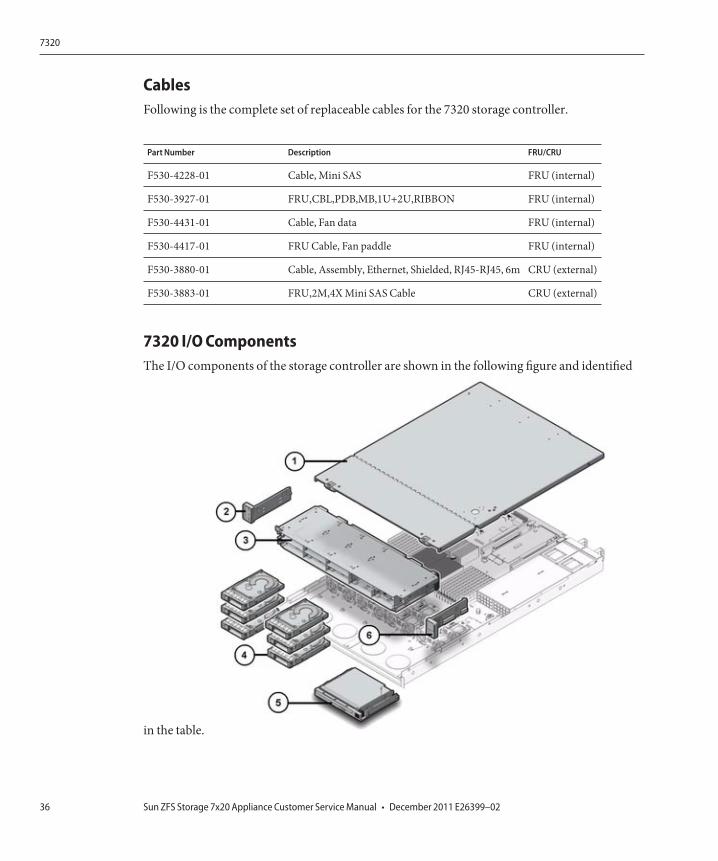
CablesFollowing is the complete set of replaceable cables for the 7320 storage controller.
Part Number Description FRU/CRU
F530-4228-01 Cable, Mini SAS FRU (internal)
F530-3927-01 FRU,CBL,PDB,MB,1U+2U,RIBBON FRU (internal)
F530-4431-01 Cable, Fan data FRU (internal)
F530-4417-01 FRU Cable, Fan paddle FRU (internal)
F530-3880-01 Cable, Assembly, Ethernet, Shielded, RJ45-RJ45, 6m CRU (external)
F530-3883-01 FRU,2M,4X Mini SAS Cable CRU (external)
7320 I/O ComponentsThe I/O components of the storage controller are shown in the following figure and identified
in the table.
7320
Sun ZFS Storage 7x20 Appliance Customer Service Manual • December 2011 E26399–0236
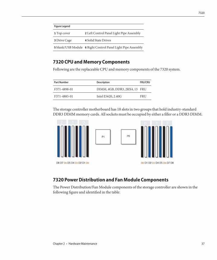
Figure Legend
1 Top cover 2 Left Control Panel Light Pipe Assembly
3 Drive Cage 4 Solid State Drives
5 blank/USB Module 6 Right Control Panel Light Pipe Assembly
7320 CPU and Memory ComponentsFollowing are the replaceable CPU and memory components of the 7320 system.
Part Number Description FRU/CRU
F371-4898-01 DIMM, 4GB, DDR3, 2RX4, 13 FRU
F371-4885-01 Intel E5620, 2.40G FRU
The storage controller motherboard has 18 slots in two groups that hold industry-standardDDR3 DIMM memory cards. All sockets must be occupied by either a filler or a DDR3 DIMM.
7320 Power Distribution and Fan Module ComponentsThe Power Distribution/Fan Module components of the storage controller are shown in thefollowing figure and identified in the table.
7320
Chapter 2 • Hardware Maintenance 37
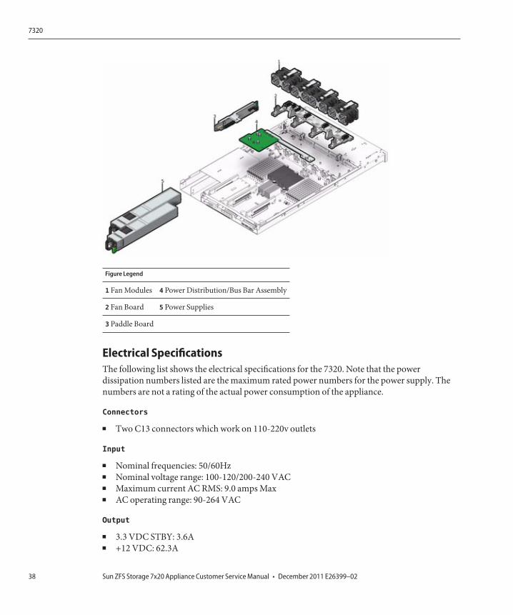
Figure Legend
1 Fan Modules 4 Power Distribution/Bus Bar Assembly
2 Fan Board 5 Power Supplies
3 Paddle Board
Electrical SpecificationsThe following list shows the electrical specifications for the 7320. Note that the powerdissipation numbers listed are the maximum rated power numbers for the power supply. Thenumbers are not a rating of the actual power consumption of the appliance.
Connectors
■ Two C13 connectors which work on 110-220v outlets
Input
■ Nominal frequencies: 50/60Hz■ Nominal voltage range: 100-120/200-240 VAC■ Maximum current AC RMS: 9.0 amps Max■ AC operating range: 90-264 VAC
Output
■ 3.3 VDC STBY: 3.6A■ +12 VDC: 62.3A
7320
Sun ZFS Storage 7x20 Appliance Customer Service Manual • December 2011 E26399–0238
Power dissipation
■ Max power consumption: 873 W■ Max heat output: 2977 BTU/hr■ Volt-Ampere rating: 891 VA @ 240 VAC, 0.98P.F.
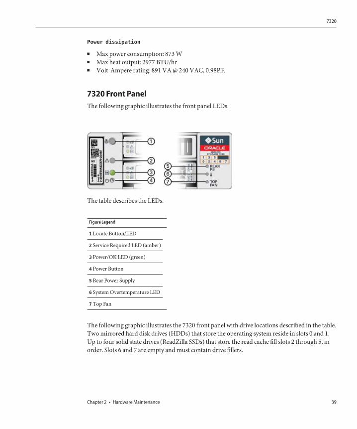
7320 Front PanelThe following graphic illustrates the front panel LEDs.
The table describes the LEDs.
Figure Legend
1 Locate Button/LED
2 Service Required LED (amber)
3 Power/OK LED (green)
4 Power Button
5 Rear Power Supply
6 System Overtemperature LED
7 Top Fan
The following graphic illustrates the 7320 front panel with drive locations described in the table.Two mirrored hard disk drives (HDDs) that store the operating system reside in slots 0 and 1.Up to four solid state drives (ReadZilla SSDs) that store the read cache fill slots 2 through 5, inorder. Slots 6 and 7 are empty and must contain drive fillers.
7320
Chapter 2 • Hardware Maintenance 39

Disk DriveLocations
HDD1 HDD3 HDD5
HDD0 HDD2 HDD4 HDD6 HDD7
7320 Replaceable ComponentsFollowing is the complete list of replaceable power distribution, disk, and fan modulecomponents of the 7320 system. Note that power supplies, disks, and fan modules arehot-pluggable on the storage controller.
Part Number Description FRU/CRU
F300-2233-02 RoHS 760W Power Supply CRU
F541-2075-04 Buss Bar Power, 1U FRU
F542-0184-01 DR, 3Gb SATA CRU
F542-0330-01 2.5" 512GB ReadZilla SSD CRU
F541-276-01 ASSY,FAN Module CRU
F541-4274-02 Fan Board (1U) FRU
7320 PCIe Cards and RisersFollowing is the complete list of replaceable PCIe cards for the 7320 system.
Part Number Description FRU/CRU
F371-4325-01 8Gb FC HBA (PCIe) CRU
F375-3609-02 PCA, SAS 6GBS 8 Port (PCIe) CRU
F375-3606-03 Dual Port (x4) IB HCA (PCIe) CRU
F375-3696-01 Dual Port CX2 4XQDR (PCIe) CRU
F375-3617-01 2X10GbE SFP+, X8 (PCIe) CRU
F375-3481-01 NIC Card Quad Port 1GigE Cu (PCIe) CRU
F511-1496-04 Sun Fishworks Cluster Controller 200 (PCIe) FRU
7320
Sun ZFS Storage 7x20 Appliance Customer Service Manual • December 2011 E26399–0240
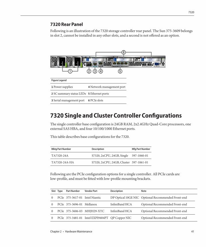
7320 Rear PanelFollowing is an illustration of the 7320 storage controller rear panel. The Sun 375-3609 belongsin slot 2, cannot be installed in any other slots, and a second is not offered as an option.
Figure Legend
1 Power supplies 4 Network management port
2 SC summary status LEDs 5 Ethernet ports
3 Serial management port 6 PCIe slots
7320 Single and Cluster Controller ConfigurationsThe single controller base configuration is 24GB RAM, 2x2.4GHz Quad-Core processors, oneexternal SAS HBA, and four 10/100/1000 Ethernet ports.
This table describes base configurations for the 7320.
Mktg Part Number Description Mfg Part Number
TA7320-24A S7320, 2xCPU, 24GB, Single 597-1060-01
TA7320-24A-HA S7320, 2xCPU, 24GB, Cluster 597-1061-01
Following are the PCIe configuration options for a single controller. All PCIe cards arelow-profile, and must be fitted with low-profile mounting brackets.
Slot Type Part Number Vendor Part Description Note
0 PCIe 375-3617-01 Intel Niantic DP Optical 10GE NIC Optional Recommended Front-end
0 PCIe 375-3696-01 Mellanox InfiniBand HCA Optional Recommended Front-end
0 PCIe 375-3606-03 MHJH29-XTC InfiniBand HCA Optional Recommended Front-end
0 PCIe 375-3481-01 Intel EXPI9404PT QP Copper NIC Optional Recommended Front-end
7320
Chapter 2 • Hardware Maintenance 41

Slot Type Part Number Vendor Part Description Note
0 PCIe 371-4325-01 QLogic 8Gb DP FC HBA Optional FC Target or Initiator (Backup)
1 PCIe 375-3617-01 Intel Niantic DP Optical 10GE NIC Optional Recommended Front-end
1 PCIe 375-3696-01 Mellanox InfiniBand HCA Optional Recommended Front-end
1 PCIe 375-3606-03 MHJH29-XTC InfiniBand HCA Optional Recommended Front-end
1 PCIe 375-3481-01 Intel EXPI9404PT QP Copper NIC Optional Recommended Front-end
1 PCIe 371-4325-01 QLogic 8Gb DP FC HBA Optional FC Target or Initiator (Backup)
2 PCIe 375-3609-03 Sun Thebe External SAS HBA Base Configuration
7320 Cluster ConfigurationsThe 7320 cluster base configuration is 24GB RAM, 2x2.4GHz Quad-Core processors, oneexternal SAS HBA, and four 10/100/1000 Ethernet ports, and a Cluster card. The Sun Storage7420C Cluster Upgrade Kit (XOPT 594-4680-01) contains two cluster cards with cables forconverting two 7320 or two 7420 controllers to a cluster.
The following options are available for clustered storage controllers. Note that both storagecontrollers in a cluster must be configured identically with regard to card configurations and alloptional NIC/HBA card configurations chosen for clustered storage controllers must beidentical in both chassis.
Slot Type Part Number Vendor Part Description Note
0 PCIe 375-3617-01 Intel Niantic DP Optical 10GE NIC Optional Recommended Front-end
0 PCIe 375-3696-01 Mellanox InfiniBand HCA Optional Recommended Front-end
0 PCIe 375-3606-03 MHJH29-XTC InfiniBand HCA Optional Recommended Front-end
0 PCIe 375-3481-01 Intel EXPI9404PT QP Copper NIC Optional Recommended Front-end
0 PCIe 371-4325-01 QLogic 8Gb DP FC HBA Optional FC Target or Initiator (Backup)
1 PCIe 542-0298-01 Sun Fishworks Cluster Card 2 Cluster Base Configuration
2 PCIe 375-3609-03 Sun Thebe External SAS HBA Cluster Base Configuration
7320 Connector Pinouts
The serial management connector (SERIAL MGT) is an RJ-45 connector and a terminalconnection to the SP console.
7320
Sun ZFS Storage 7x20 Appliance Customer Service Manual • December 2011 E26399–0242
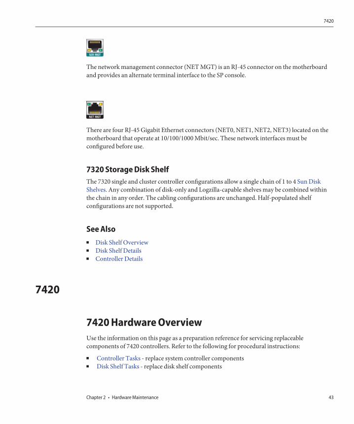
The network management connector (NET MGT) is an RJ-45 connector on the motherboardand provides an alternate terminal interface to the SP console.
There are four RJ-45 Gigabit Ethernet connectors (NET0, NET1, NET2, NET3) located on themotherboard that operate at 10/100/1000 Mbit/sec. These network interfaces must beconfigured before use.
7320 Storage Disk ShelfThe 7320 single and cluster controller configurations allow a single chain of 1 to 4 Sun DiskShelves. Any combination of disk-only and Logzilla-capable shelves may be combined withinthe chain in any order. The cabling configurations are unchanged. Half-populated shelfconfigurations are not supported.
See Also■ Disk Shelf Overview■ Disk Shelf Details■ Controller Details
7420
7420 Hardware OverviewUse the information on this page as a preparation reference for servicing replaceablecomponents of 7420 controllers. Refer to the following for procedural instructions:
■ Controller Tasks - replace system controller components■ Disk Shelf Tasks - replace disk shelf components
7420
Chapter 2 • Hardware Maintenance 43
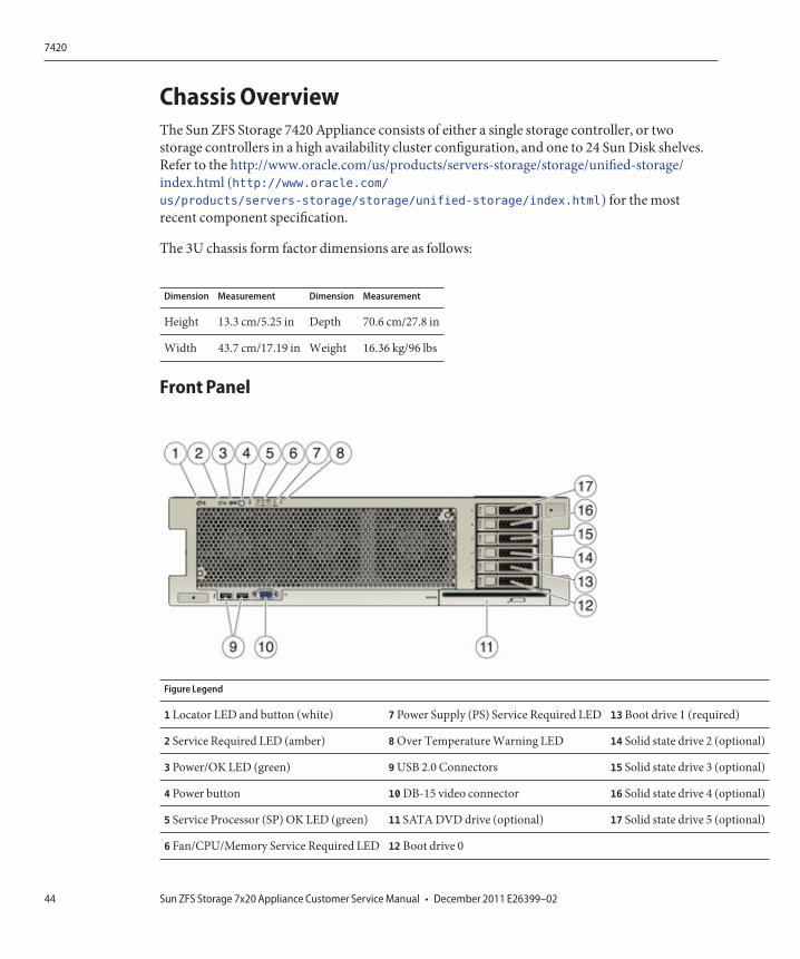
Chassis OverviewThe Sun ZFS Storage 7420 Appliance consists of either a single storage controller, or twostorage controllers in a high availability cluster configuration, and one to 24 Sun Disk shelves.Refer to the http://www.oracle.com/us/products/servers-storage/storage/unified-storage/index.html (http://www.oracle.com/us/products/servers-storage/storage/unified-storage/index.html) for the mostrecent component specification.
The 3U chassis form factor dimensions are as follows:
Dimension Measurement Dimension Measurement
Height 13.3 cm/5.25 in Depth 70.6 cm/27.8 in
Width 43.7 cm/17.19 in Weight 16.36 kg/96 lbs
Front Panel
Figure Legend
1 Locator LED and button (white) 7 Power Supply (PS) Service Required LED 13 Boot drive 1 (required)
2 Service Required LED (amber) 8 Over Temperature Warning LED 14 Solid state drive 2 (optional)
3 Power/OK LED (green) 9 USB 2.0 Connectors 15 Solid state drive 3 (optional)
4 Power button 10 DB-15 video connector 16 Solid state drive 4 (optional)
5 Service Processor (SP) OK LED (green) 11 SATA DVD drive (optional) 17 Solid state drive 5 (optional)
6 Fan/CPU/Memory Service Required LED 12 Boot drive 0
7420
Sun ZFS Storage 7x20 Appliance Customer Service Manual • December 2011 E26399–0244
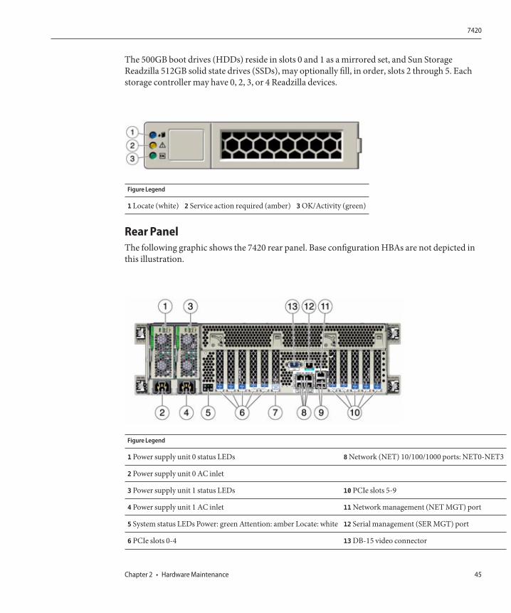
The 500GB boot drives (HDDs) reside in slots 0 and 1 as a mirrored set, and Sun StorageReadzilla 512GB solid state drives (SSDs), may optionally fill, in order, slots 2 through 5. Eachstorage controller may have 0, 2, 3, or 4 Readzilla devices.
Figure Legend
1 Locate (white) 2 Service action required (amber) 3 OK/Activity (green)
Rear PanelThe following graphic shows the 7420 rear panel. Base configuration HBAs are not depicted inthis illustration.
Figure Legend
1 Power supply unit 0 status LEDs 8 Network (NET) 10/100/1000 ports: NET0-NET3
2 Power supply unit 0 AC inlet
3 Power supply unit 1 status LEDs 10 PCIe slots 5-9
4 Power supply unit 1 AC inlet 11 Network management (NET MGT) port
5 System status LEDs Power: green Attention: amber Locate: white 12 Serial management (SER MGT) port
6 PCIe slots 0-4 13 DB-15 video connector
7420
Chapter 2 • Hardware Maintenance 45
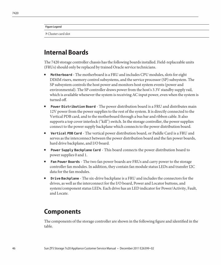
Figure Legend
7 Cluster card slot
Internal BoardsThe 7420 storage controller chassis has the following boards installed. Field-replaceable units(FRUs) should only be replaced by trained Oracle service technicians.
■ Motherboard - The motherboard is a FRU and includes CPU modules, slots for eightDIMM risers, memory control subsystems, and the service processor (SP) subsystem. TheSP subsystem controls the host power and monitors host system events (power andenvironmental). The SP controller draws power from the host's 3.3V standby supply rail,which is available whenever the system is receiving AC input power, even when the system isturned off.
■ Power Distribution Board - The power distribution board is a FRU and distributes main12V power from the power supplies to the rest of the system. It is directly connected to theVertical PDB card, and to the motherboard through a bus bar and ribbon cable. It alsosupports a top cover interlock ("kill") switch. In the storage controller, the power suppliesconnect to the power supply backplane which connects to the power distribution board.
■ Vertical PDB Card - The vertical power distribution board, or Paddle Card is a FRU andserves as the interconnect between the power distribution board and the fan power boards,hard drive backplane, and I/O board.
■ Power Supply Backplane Card - This board connects the power distribution board topower supplies 0 and 1.
■ Fan Power Boards - The two fan power boards are FRUs and carry power to the storagecontroller fan modules. In addition, they contain fan module status LEDs and transfer I2Cdata for the fan modules.
■ Drive Backplane - The six-drive backplane is a FRU and includes the connectors for thedrives, as well as the interconnect for the I/O board, Power and Locator buttons, andsystem/component status LEDs. Each drive has an LED indicator for Power/Activity, Fault,and Locate.
ComponentsThe components of the storage controller are shown in the following figure and identified in thetable.
7420
Sun ZFS Storage 7x20 Appliance Customer Service Manual • December 2011 E26399–0246
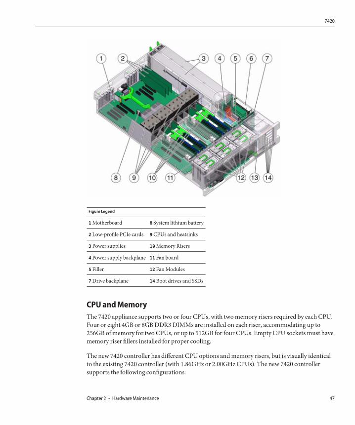
Figure Legend
1 Motherboard 8 System lithium battery
2 Low-profile PCIe cards 9 CPUs and heatsinks
3 Power supplies 10 Memory Risers
4 Power supply backplane 11 Fan board
5 Filler 12 Fan Modules
7 Drive backplane 14 Boot drives and SSDs
CPU and MemoryThe 7420 appliance supports two or four CPUs, with two memory risers required by each CPU.Four or eight 4GB or 8GB DDR3 DIMMs are installed on each riser, accommodating up to256GB of memory for two CPUs, or up to 512GB for four CPUs. Empty CPU sockets must havememory riser fillers installed for proper cooling.
The new 7420 controller has different CPU options and memory risers, but is visually identicalto the existing 7420 controller (with 1.86GHz or 2.00GHz CPUs). The new 7420 controllersupports the following configurations:
7420
Chapter 2 • Hardware Maintenance 47
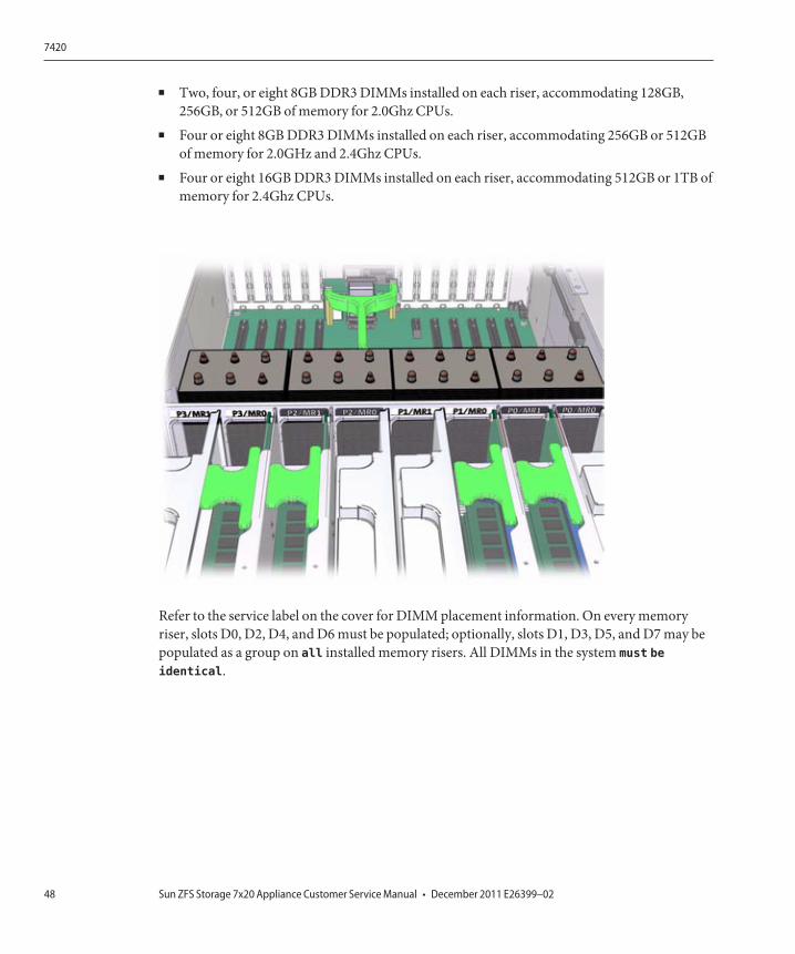
■ Two, four, or eight 8GB DDR3 DIMMs installed on each riser, accommodating 128GB,256GB, or 512GB of memory for 2.0Ghz CPUs.
■ Four or eight 8GB DDR3 DIMMs installed on each riser, accommodating 256GB or 512GBof memory for 2.0GHz and 2.4Ghz CPUs.
■ Four or eight 16GB DDR3 DIMMs installed on each riser, accommodating 512GB or 1TB ofmemory for 2.4Ghz CPUs.
Refer to the service label on the cover for DIMM placement information. On every memoryriser, slots D0, D2, D4, and D6 must be populated; optionally, slots D1, D3, D5, and D7 may bepopulated as a group on all installed memory risers. All DIMMs in the system must be
identical.
7420
Sun ZFS Storage 7x20 Appliance Customer Service Manual • December 2011 E26399–0248
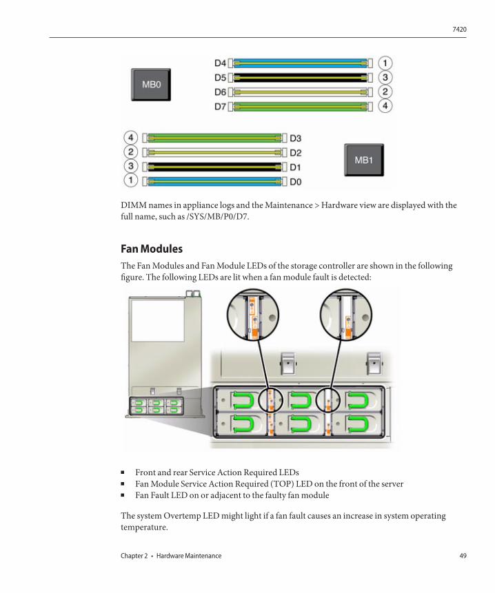
DIMM names in appliance logs and the Maintenance > Hardware view are displayed with thefull name, such as /SYS/MB/P0/D7.
Fan ModulesThe Fan Modules and Fan Module LEDs of the storage controller are shown in the followingfigure. The following LEDs are lit when a fan module fault is detected:
■ Front and rear Service Action Required LEDs■ Fan Module Service Action Required (TOP) LED on the front of the server■ Fan Fault LED on or adjacent to the faulty fan module
The system Overtemp LED might light if a fan fault causes an increase in system operatingtemperature.
7420
Chapter 2 • Hardware Maintenance 49
PCIe CardsThe Sun Fishworks Cluster Controller 200 belongs in the Cluster slot (C) only. SAS HBAs mustall be of the same type, installed in slots 1 and 8, with an optional third SAS HBA in slot 2, andan optional fourth SAS HBA in slot 7. PCIe slots should be populated in the following order: 9(if used), 0 (if used), 7, 2, 6, 3, 5, 4.
ConnectorsThe serial management connector (SER MGT) is an RJ-45 connector and provides a terminal
connection to the SP console.
The network management connector (NET MGT) is an RJ-45 connector and provides a LAN
interface to the SP console.
There are four RJ-45 Gigabit Ethernet connectors (NET0, NET1, NET2, NET3) located on themotherboard that operate at 10/100/1000 Mbit/sec. These network interfaces must beconfigured before use.
7420 Standalone and Cluster ControllerConfigurationsThe following tables show the configuration options for a single standalone 7420 controller ortwo clustered 7420 controllers. All PCIe cards are low-profile, and must be fitted withlow-profile mounting brackets.
Standalone Base OptionsThis table describes 7420 standalone base configurations. Note: both 7100566 and 7100568include a cluster card and can be configured as a single standalone or two clusteredconfiguration.
Mktg Part Number Description Mfg Part Number
TA7420-26A S7420, no DIMMs, 2x1.86GHz-6C 597-0789-01
TA7420-28A S7420, no DIMMs, 2x2.00GHz-8C 597-0790-01
7100566 S7420, no DIMMs, 4x2GHz-8C 7014572
7100568 S7420, no DIMMs, 4x2.40GHz-10C 7014573
7420
Sun ZFS Storage 7x20 Appliance Customer Service Manual • December 2011 E26399–0250
Cluster Base OptionsThis table describes 7420 cluster base configurations.
Mktg Part Number Description Mfg Part Number
TA7420-26AR00HA S7420, no DIMMs, 2x1.86GHz-6C, Cluster 597-0795-01
TC7420-28AR00HA S7420, no DIMMs, 2x2.00GHz-8C, Cluster 597-0792-01
7100566 S7420, no DIMMs, 4x2GHz-8C, Cluster 7014572
7100568 S7420, no DIMMs, 4x2.40GHz-10C, Cluster 7014573
NIC/HBA OptionsThis table describes NIC/HBA options for 7420 single and cluster configurations.
Mktg Part Number Description Mfg Part Number
SG-XPCIESAS-GEN2-Z 2-port External Sun Thebe SAS (x4) HBA, PCIe F375-3609-03
SG-XPCIE2FC-QF8-Z 2-port FC HBA, 8Gb, PCIe 594-5684-01
X4446A-Z 4-port PCIe Quad GigE UTP 594-4024-01
X4237A 2-port 4X IB HCA PCIe 594-5862-02
X1109A-Z 2-port 10Gig SFP+ NIC, PCIe 594-6039-01
X2129A XCVRm 850NM, 1/10GPS, Short Reach, SFP 594-6508-01
PCIe OptionsThis table describes the supported single and clustered PCIe configuration option summary for7420.
Slot TypeSun PartNumber Description Note
0 PCIe 371-4325-01 8Gb DP FC HBA Optional FC Target or Initiator (Backup)
1 PCIe 375-3609-02 DP SAS-2 HBA Base Configuration
2 PCIe 375-3609-02 DP SAS-2 HBA Additional Optional Back-end
2 PCIe 375-3481-01 QP Copper NIC Optional Recommended Front-end
2 PCIe 371-4325-01 8Gb DP FC HBA Optional FC Target or Initiator (Backup)
2 PCIe 375-3606-01 Infiniband HCA Optional Recommended Front-end
7420
Chapter 2 • Hardware Maintenance 51
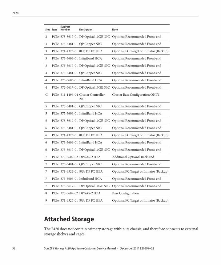
Slot TypeSun PartNumber Description Note
2 PCIe 375-3617-01 DP Optical 10GE NIC Optional Recommended Front-end
3 PCIe 375-3481-01 QP Copper NIC Optional Recommended Front-end
3 PCIe 371-4325-01 8Gb DP FC HBA Optional FC Target or Initiator (Backup)
3 PCIe 375-3606-01 Infiniband HCA Optional Recommended Front-end
3 PCIe 375-3617-01 DP Optical 10GE NIC Optional Recommended Front-end
4 PCIe 375-3481-01 QP Copper NIC Optional Recommended Front-end
4 PCIe 375-3606-01 InfiniBand HCA Optional Recommended Front-end
4 PCIe 375-3617-01 DP Optical 10GE NIC Optional Recommended Front-end
C PCIe 511-1496-04 Cluster Controller200
Cluster Base Configuration ONLY
5 PCIe 375-3481-01 QP Copper NIC Optional Recommended Front-end
5 PCIe 375-3606-01 InfiniBand HCA Optional Recommended Front-end
5 PCIe 375-3617-01 DP Optical 10GE NIC Optional Recommended Front-end
6 PCIe 375-3481-01 QP Copper NIC Optional Recommended Front-end
6 PCIe 371-4325-01 8Gb DP FC HBA Optional FC Target or Initiator (Backup)
6 PCIe 375-3606-01 InfiniBand HCA Optional Recommended Front-end
6 PCIe 375-3617-01 DP Optical 10GE NIC Optional Recommended Front-end
7 PCIe 375-3609-02 DP SAS-2 HBA Additional Optional Back-end
7 PCIe 375-3481-01 QP Copper NIC Optional Recommended Front-end
7 PCIe 371-4325-01 8Gb DP FC HBA Optional FC Target or Initiator (Backup)
7 PCIe 375-3606-01 Infiniband HCA Optional Recommended Front-end
7 PCIe 375-3617-01 DP Optical 10GE NIC Optional Recommended Front-end
8 PCIe 375-3609-02 DP SAS-2 HBA Base Configuration
9 PCIe 371-4325-01 8Gb DP FC HBA Optional FC Target or Initiator (Backup)
Attached StorageThe 7420 does not contain primary storage within its chassis, and therefore connects to externalstorage shelves and cages.
7420
Sun ZFS Storage 7x20 Appliance Customer Service Manual • December 2011 E26399–0252
Disk ShelfThe 7420 single and cluster controller configurations allow one to four chains of 1 to 6 Sun DiskShelves. Any combination of disk-only and Logzilla-capable shelves may be combined withinthe chain in any order. The cabling configurations are unchanged. Half-populated shelfconfigurations are not supported.
See Disk Shelf Overview for component specifications and diagrams.
7x20
7x20 CRU Maintenance ProceduresThis section provides instructions on how to replace customer replaceable components (CRUs)in Oracle's Sun ZFS Storage 7120, 7320, and 7420 controllers.
Refer to Disk Shelf Details for replacing expansion storage shelf components.
PrerequisitesRead the information in the overview section for your model to become familiar with thereplaceable parts of the system:
■ 7120 Overview■ 7320 Overview■ 7420 Overview
Caution: Read and follow the instructions in the Safety Information and Required Tools andInformation sections.
Safety InformationThis section contains safety information that you must follow when servicing the storagesystem. For your protection, observe the following safety precautions when setting up yourequipment:
■ Do not remove the side panels, or run the storage system with the side panels removed.Hazardous voltage is present that could cause injury. The covers and panels must be in placefor proper air flow to prevent equipment damage.
■ Follow all cautions, warnings, and instructions marked on the equipment and described inImportant Safety Information for Sun Hardware Systems.
7x20
Chapter 2 • Hardware Maintenance 53
■ Ensure that the voltage and frequency of your power source match the voltage inscribed onthe electrical rating label.
■ Follow the electrostatic discharge safety practices. Electrostatic discharge (ESD) sensitivedevices, such as PCI cards, HDDs, SSDs, and memory cards, require special handling.Circuit boards and HDDs contain electronic components that are extremely sensitive tostatic electricity. Ordinary amounts of static electricity from clothing or the workenvironment can destroy the components located on these boards. Do not touch thecomponents without using antistatic precautions, especially along the connector edges.
Required Tools and InformationThe following tools are needed to service the CRUs:■ Antistatic wrist strap - Wear an antistatic wrist strap and use an antistatic mat when
handling components such as HDDs, LCCs, or PCI cards. When servicing or removingstorage controller components, attach an antistatic strap to your wrist and then to a metalarea on the chassis. Following this practice equalizes the electrical potentials between youand the storage controller.
■ Antistatic mat - Place static-sensitive components on an antistatic mat.■ No. 2 Phillips screwdriver■ Nonconducting, No.1 flat-blade screwdriver or equivalent■ Nonconducting stylus or pencil (to power on the storage controller)
Chassis Serial NumberTo obtain support for your storage controller or to order new parts, you need your chassis serialnumber. You can find a chassis serial number label on the storage controller front panel on theleft side. Another label is on the top of the storage controller. Alternatively, click the Sun logo inthe BUI masthead to obtain the serial number or issue the following command:
hostname: maintenance hardware show
Controller Replacement Tasks
7x20 Controller Replacement Tasks
HDD or SSD
1. Identify the failed HDD or SSD by going to the Maintenance > Hardware section of the BUIand clicking the drive details icon . If you are physically at the system, the amber ServiceRequired indicator on the HDD or SSD should be illuminated.
7x20
Sun ZFS Storage 7x20 Appliance Customer Service Manual • December 2011 E26399–0254
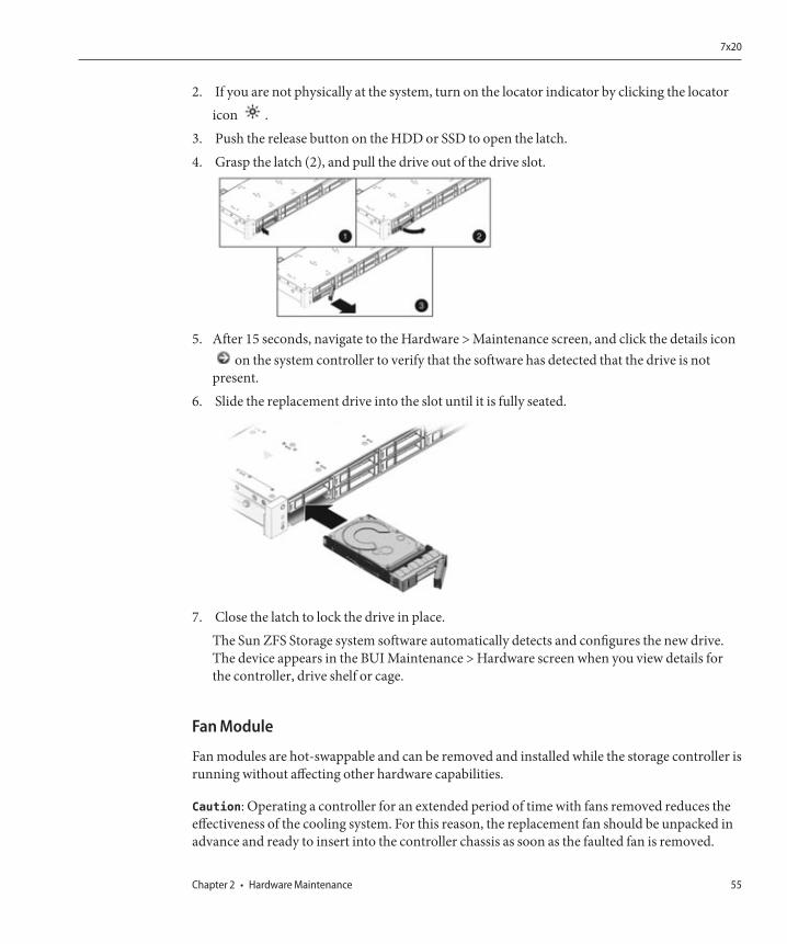
2. If you are not physically at the system, turn on the locator indicator by clicking the locatoricon .
3. Push the release button on the HDD or SSD to open the latch.4. Grasp the latch (2), and pull the drive out of the drive slot.
5. After 15 seconds, navigate to the Hardware > Maintenance screen, and click the details iconon the system controller to verify that the software has detected that the drive is not
present.6. Slide the replacement drive into the slot until it is fully seated.
7. Close the latch to lock the drive in place.The Sun ZFS Storage system software automatically detects and configures the new drive.The device appears in the BUI Maintenance > Hardware screen when you view details forthe controller, drive shelf or cage.
Fan Module
Fan modules are hot-swappable and can be removed and installed while the storage controller isrunning without affecting other hardware capabilities.
Caution: Operating a controller for an extended period of time with fans removed reduces theeffectiveness of the cooling system. For this reason, the replacement fan should be unpacked inadvance and ready to insert into the controller chassis as soon as the faulted fan is removed.
7x20
Chapter 2 • Hardware Maintenance 55
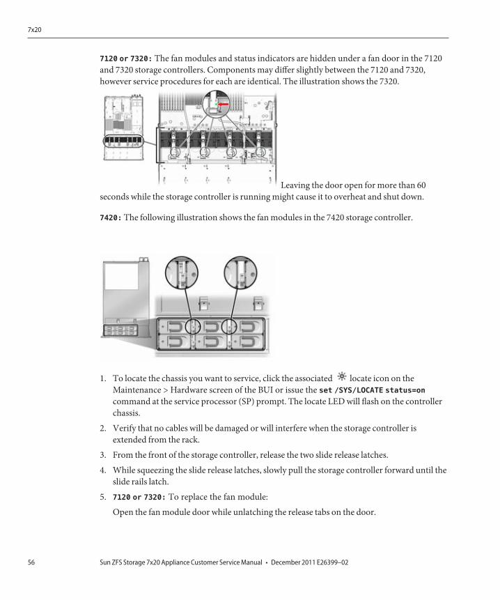
7120 or 7320: The fan modules and status indicators are hidden under a fan door in the 7120and 7320 storage controllers. Components may differ slightly between the 7120 and 7320,however service procedures for each are identical. The illustration shows the 7320.
Leaving the door open for more than 60seconds while the storage controller is running might cause it to overheat and shut down.
7420: The following illustration shows the fan modules in the 7420 storage controller.
1. To locate the chassis you want to service, click the associated locate icon on theMaintenance > Hardware screen of the BUI or issue the set /SYS/LOCATE status=oncommand at the service processor (SP) prompt. The locate LED will flash on the controllerchassis.
2. Verify that no cables will be damaged or will interfere when the storage controller isextended from the rack.
3. From the front of the storage controller, release the two slide release latches.
4. While squeezing the slide release latches, slowly pull the storage controller forward until theslide rails latch.
5. 7120 or 7320: To replace the fan module:
Open the fan module door while unlatching the release tabs on the door.
7x20
Sun ZFS Storage 7x20 Appliance Customer Service Manual • December 2011 E26399–0256
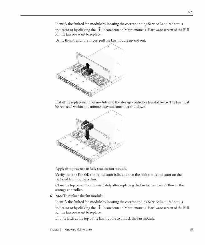
Identify the faulted fan module by locating the corresponding Service Required statusindicator or by clicking the locate icon on Maintenance > Hardware screen of the BUIfor the fan you want to replace.Using thumb and forefinger, pull the fan module up and out.
Install the replacement fan module into the storage controller fan slot. Note: The fan mustbe replaced within one minute to avoid controller shutdown.
Apply firm pressure to fully seat the fan module.Verify that the Fan OK status indicator is lit, and that the fault status indicator on thereplaced fan module is dim.Close the top cover door immediately after replacing the fan to maintain airflow in thestorage controller.
6. 7420 To replace the fan module:Identify the faulted fan module by locating the corresponding Service Required statusindicator or by clicking the locate icon on Maintenance > Hardware screen of the BUIfor the fan you want to replace.Lift the latch at the top of the fan module to unlock the fan module.
7x20
Chapter 2 • Hardware Maintenance 57
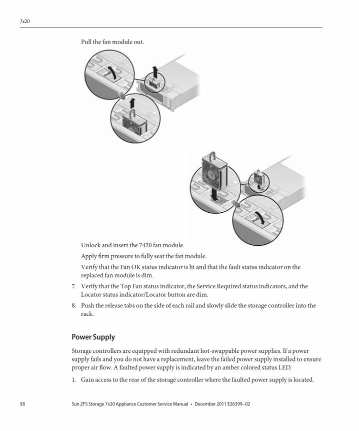
Pull the fan module out.
Unlock and insert the 7420 fan module.
Apply firm pressure to fully seat the fan module.
Verify that the Fan OK status indicator is lit and that the fault status indicator on thereplaced fan module is dim.
7. Verify that the Top Fan status indicator, the Service Required status indicators, and theLocator status indicator/Locator button are dim.
8. Push the release tabs on the side of each rail and slowly slide the storage controller into therack.
Power Supply
Storage controllers are equipped with redundant hot-swappable power supplies. If a powersupply fails and you do not have a replacement, leave the failed power supply installed to ensureproper air flow. A faulted power supply is indicated by an amber colored status LED.
1. Gain access to the rear of the storage controller where the faulted power supply is located.
7x20
Sun ZFS Storage 7x20 Appliance Customer Service Manual • December 2011 E26399–0258
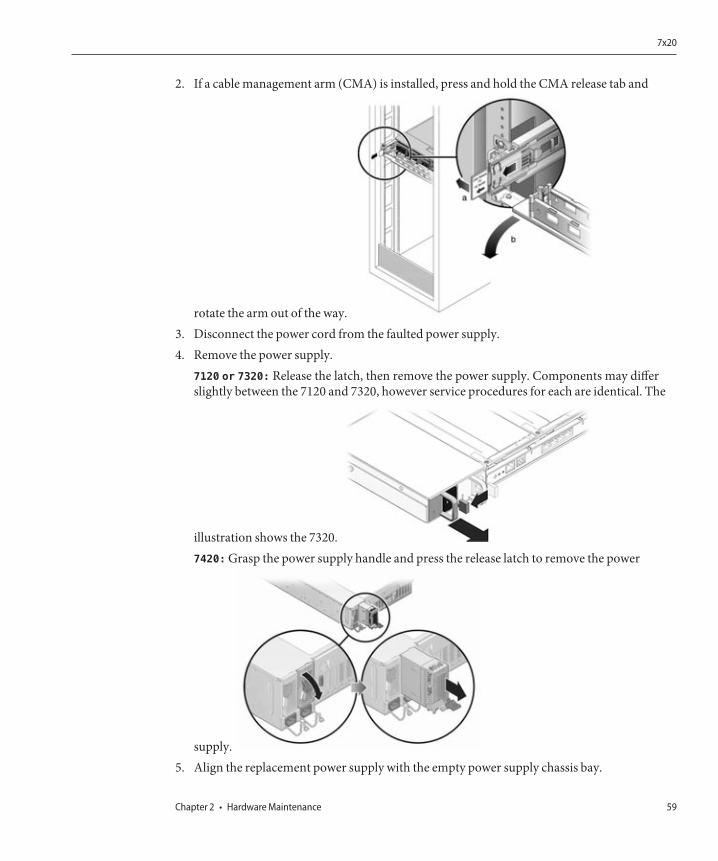
2. If a cable management arm (CMA) is installed, press and hold the CMA release tab and
rotate the arm out of the way.3. Disconnect the power cord from the faulted power supply.4. Remove the power supply.
7120 or 7320: Release the latch, then remove the power supply. Components may differslightly between the 7120 and 7320, however service procedures for each are identical. The
illustration shows the 7320.7420: Grasp the power supply handle and press the release latch to remove the power
supply.5. Align the replacement power supply with the empty power supply chassis bay.
7x20
Chapter 2 • Hardware Maintenance 59
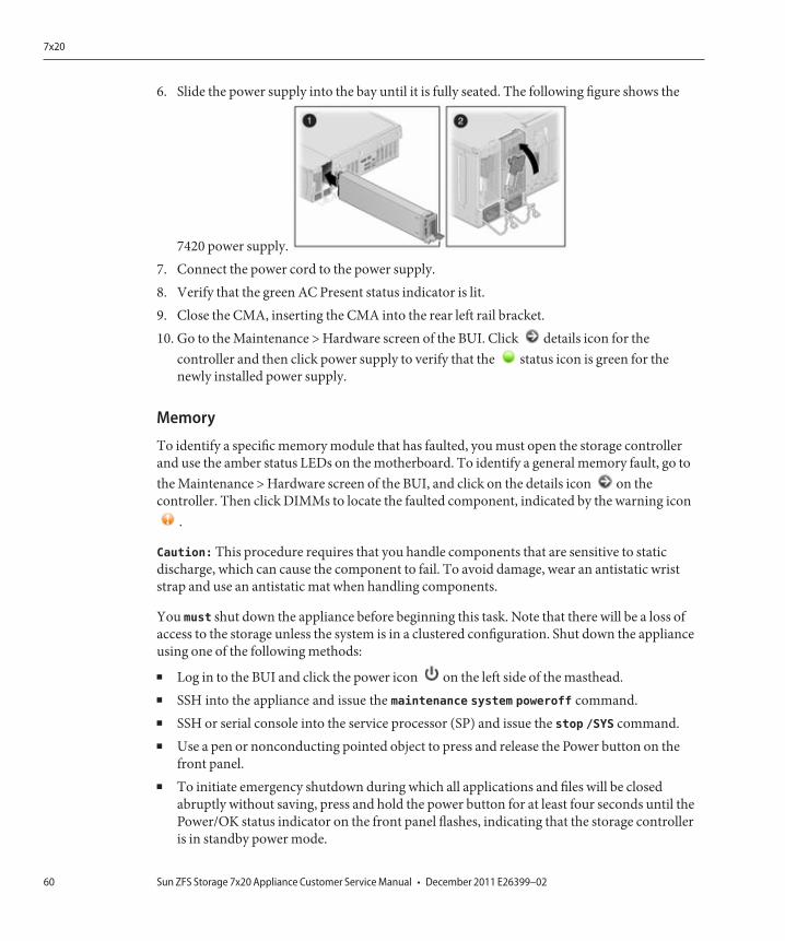
6. Slide the power supply into the bay until it is fully seated. The following figure shows the
7420 power supply.7. Connect the power cord to the power supply.8. Verify that the green AC Present status indicator is lit.9. Close the CMA, inserting the CMA into the rear left rail bracket.10. Go to the Maintenance > Hardware screen of the BUI. Click details icon for the
controller and then click power supply to verify that the status icon is green for thenewly installed power supply.
Memory
To identify a specific memory module that has faulted, you must open the storage controllerand use the amber status LEDs on the motherboard. To identify a general memory fault, go tothe Maintenance > Hardware screen of the BUI, and click on the details icon on thecontroller. Then click DIMMs to locate the faulted component, indicated by the warning icon
.
Caution: This procedure requires that you handle components that are sensitive to staticdischarge, which can cause the component to fail. To avoid damage, wear an antistatic wriststrap and use an antistatic mat when handling components.
You must shut down the appliance before beginning this task. Note that there will be a loss ofaccess to the storage unless the system is in a clustered configuration. Shut down the applianceusing one of the following methods:
■ Log in to the BUI and click the power icon on the left side of the masthead.■ SSH into the appliance and issue the maintenance system poweroff command.■ SSH or serial console into the service processor (SP) and issue the stop /SYS command.■ Use a pen or nonconducting pointed object to press and release the Power button on the
front panel.■ To initiate emergency shutdown during which all applications and files will be closed
abruptly without saving, press and hold the power button for at least four seconds until thePower/OK status indicator on the front panel flashes, indicating that the storage controlleris in standby power mode.
7x20
Sun ZFS Storage 7x20 Appliance Customer Service Manual • December 2011 E26399–0260
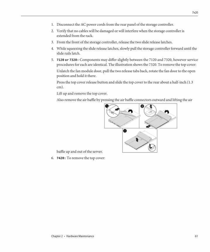
1. Disconnect the AC power cords from the rear panel of the storage controller.
2. Verify that no cables will be damaged or will interfere when the storage controller isextended from the rack.
3. From the front of the storage controller, release the two slide release latches.
4. While squeezing the slide release latches, slowly pull the storage controller forward until theslide rails latch.
5. 7120 or 7320: Components may differ slightly between the 7120 and 7320, however serviceprocedures for each are identical. The illustration shows the 7320. To remove the top cover:
Unlatch the fan module door, pull the two release tabs back, rotate the fan door to the openposition and hold it there.
Press the top cover release button and slide the top cover to the rear about a half-inch (1.3cm).
Lift up and remove the top cover.
Also remove the air baffle by pressing the air baffle connectors outward and lifting the air
baffle up and out of the server.
6. 7420: To remove the top cover:
7x20
Chapter 2 • Hardware Maintenance 61
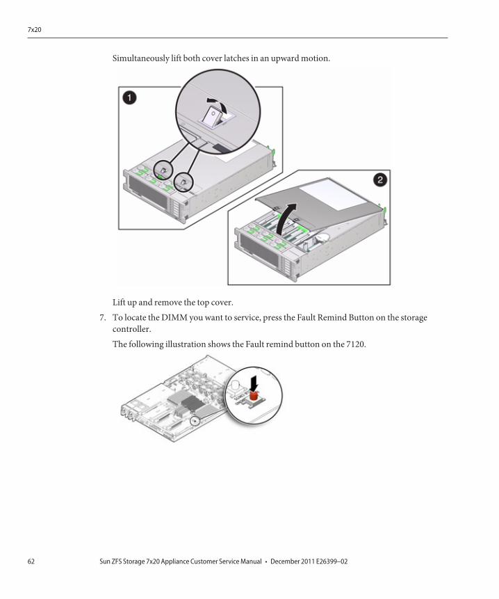
Simultaneously lift both cover latches in an upward motion.
Lift up and remove the top cover.
7. To locate the DIMM you want to service, press the Fault Remind Button on the storagecontroller.
The following illustration shows the Fault remind button on the 7120.
7x20
Sun ZFS Storage 7x20 Appliance Customer Service Manual • December 2011 E26399–0262
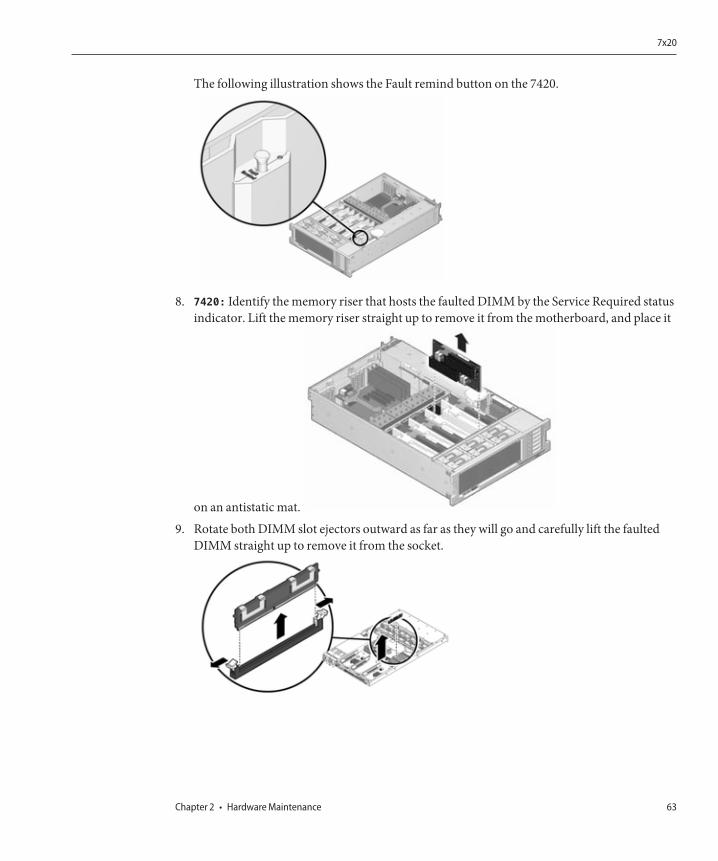
The following illustration shows the Fault remind button on the 7420.
8. 7420: Identify the memory riser that hosts the faulted DIMM by the Service Required statusindicator. Lift the memory riser straight up to remove it from the motherboard, and place it
on an antistatic mat.
9. Rotate both DIMM slot ejectors outward as far as they will go and carefully lift the faultedDIMM straight up to remove it from the socket.
7x20
Chapter 2 • Hardware Maintenance 63
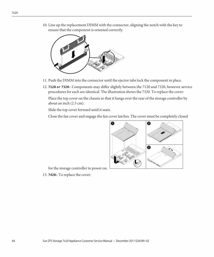
10. Line up the replacement DIMM with the connector, aligning the notch with the key toensure that the component is oriented correctly.
11. Push the DIMM into the connector until the ejector tabs lock the component in place.
12. 7120 or 7320: Components may differ slightly between the 7120 and 7320, however serviceprocedures for each are identical. The illustration shows the 7320. To replace the cover:
Place the top cover on the chassis so that it hangs over the rear of the storage controller byabout an inch (2.5 cm).
Slide the top cover forward until it seats.
Close the fan cover and engage the fan cover latches. The cover must be completely closed
for the storage controller to power on.
13. 7420: To replace the cover:
7x20
Sun ZFS Storage 7x20 Appliance Customer Service Manual • December 2011 E26399–0264
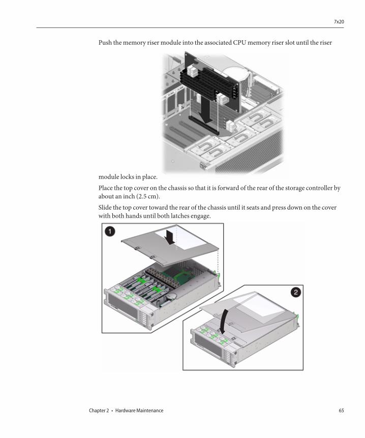
Push the memory riser module into the associated CPU memory riser slot until the riser
module locks in place.
Place the top cover on the chassis so that it is forward of the rear of the storage controller byabout an inch (2.5 cm).
Slide the top cover toward the rear of the chassis until it seats and press down on the coverwith both hands until both latches engage.
7x20
Chapter 2 • Hardware Maintenance 65
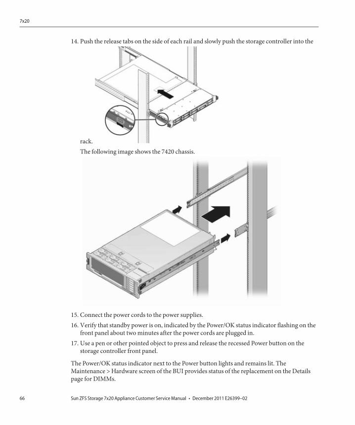
14. Push the release tabs on the side of each rail and slowly push the storage controller into the
rack.The following image shows the 7420 chassis.
15. Connect the power cords to the power supplies.16. Verify that standby power is on, indicated by the Power/OK status indicator flashing on the
front panel about two minutes after the power cords are plugged in.17. Use a pen or other pointed object to press and release the recessed Power button on the
storage controller front panel.
The Power/OK status indicator next to the Power button lights and remains lit. TheMaintenance > Hardware screen of the BUI provides status of the replacement on the Detailspage for DIMMs.
7x20
Sun ZFS Storage 7x20 Appliance Customer Service Manual • December 2011 E26399–0266
PCIe Cards and Risers
Go to the Maintenance > Hardware screen of the BUI and click the details icon on thecontroller, and then click Slots to locate the faulted component.
Caution: This procedure requires that you handle components that are sensitive to staticdischarge, which can cause the component to fail. To avoid damage, wear an antistatic wriststrap and use an antistatic mat when handling components.
Note that the 7120 Sun Flash Accelerator F20 card is a FRU and must be replaced by an Oracleservice representative.
All HBAs must be of the same type. Ensure that you upgrade your system software beforeinstalling a newly-released HBA.
You must shut down the controller before beginning this task. Note that there will be a loss ofaccess to the storage unless the system is in a clustered configuration. Shut down the applianceusing one of the following methods:
■ Log in to the BUI, and click the power icon on the left side of the masthead.■ SSH into the storage system and issue the maintenance system poweroff command.■ SSH or serial console into the service processor (SP) and issue the stop /SYS command.■ Use a pen or non-conducting pointed object to press and release the Power button on the
front panel.■ To initiate emergency shutdown, wherein all applications and files will be closed abruptly
without saving, press and hold the power button for at least four seconds until thePower/OK status indicator on the front panel flashes, indicating that the storage controlleris in standby power mode.
1. Disconnect the AC power cords from the rear panel of the storage controller.2. Verify that no cables will be damaged or will interfere when the storage controller is
extended from the rack.3. From the front of the storage controller, release the two slide release latches.4. While squeezing the slide release latches, slowly pull the storage controller forward until the
slide rails latch.5. 7120 or 7320: To remove the top cover:
Unlatch the fan module door, pull the two release tabs back, rotate the fan door to the openposition and hold it there.Press the top cover release button and slide the top cover to the rear about a half-inch (1.3cm).Lift up and remove the top cover.
6. 7420: To remove the top cover:
7x20
Chapter 2 • Hardware Maintenance 67
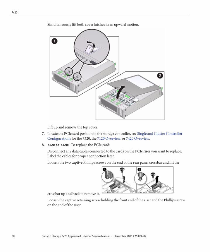
Simultaneously lift both cover latches in an upward motion.
Lift up and remove the top cover.
7. Locate the PCIe card position in the storage controller, see Single and Cluster ControllerConfigurations for the 7320, the 7120 Overview, or 7420 Overview.
8. 7120 or 7320: To replace the PCIe card:
Disconnect any data cables connected to the cards on the PCIe riser you want to replace.Label the cables for proper connection later.
Loosen the two captive Phillips screws on the end of the rear panel crossbar and lift the
crossbar up and back to remove it.
Loosen the captive retaining screw holding the front end of the riser and the Phillips screwon the end of the riser.
7x20
Sun ZFS Storage 7x20 Appliance Customer Service Manual • December 2011 E26399–0268
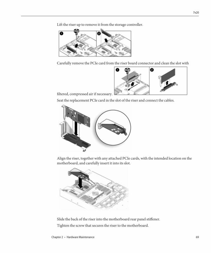
Lift the riser up to remove it from the storage controller.
Carefully remove the PCIe card from the riser board connector and clean the slot with
filtered, compressed air if necessary.
Seat the replacement PCIe card in the slot of the riser and connect the cables.
Align the riser, together with any attached PCIe cards, with the intended location on themotherboard, and carefully insert it into its slot.
Slide the back of the riser into the motherboard rear panel stiffener.Tighten the screw that secures the riser to the motherboard.
7x20
Chapter 2 • Hardware Maintenance 69
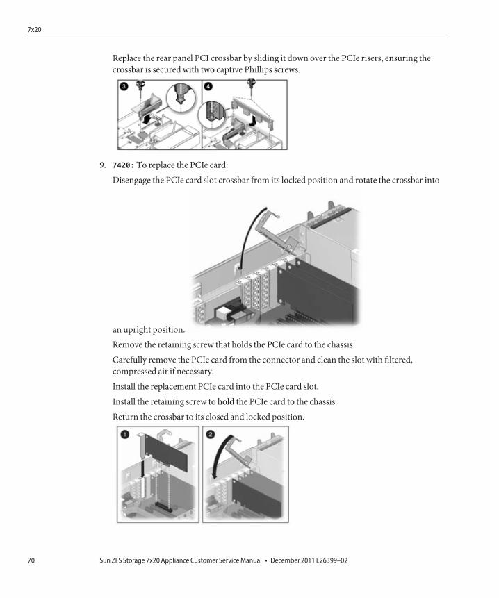
Replace the rear panel PCI crossbar by sliding it down over the PCIe risers, ensuring thecrossbar is secured with two captive Phillips screws.
9. 7420: To replace the PCIe card:
Disengage the PCIe card slot crossbar from its locked position and rotate the crossbar into
an upright position.
Remove the retaining screw that holds the PCIe card to the chassis.
Carefully remove the PCIe card from the connector and clean the slot with filtered,compressed air if necessary.
Install the replacement PCIe card into the PCIe card slot.
Install the retaining screw to hold the PCIe card to the chassis.
Return the crossbar to its closed and locked position.
7x20
Sun ZFS Storage 7x20 Appliance Customer Service Manual • December 2011 E26399–0270
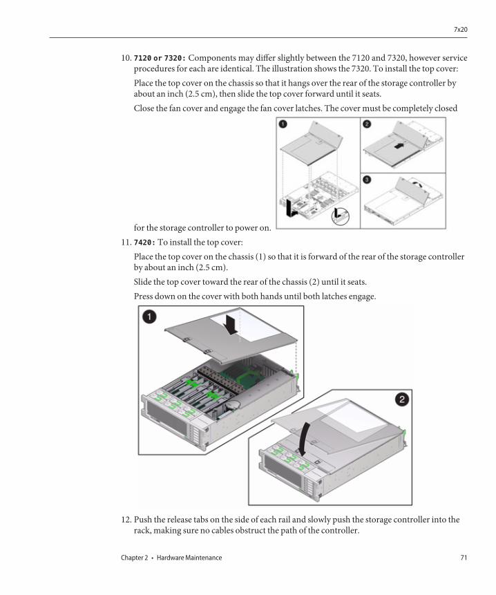
10. 7120 or 7320: Components may differ slightly between the 7120 and 7320, however serviceprocedures for each are identical. The illustration shows the 7320. To install the top cover:Place the top cover on the chassis so that it hangs over the rear of the storage controller byabout an inch (2.5 cm), then slide the top cover forward until it seats.Close the fan cover and engage the fan cover latches. The cover must be completely closed
for the storage controller to power on.11. 7420: To install the top cover:
Place the top cover on the chassis (1) so that it is forward of the rear of the storage controllerby about an inch (2.5 cm).Slide the top cover toward the rear of the chassis (2) until it seats.Press down on the cover with both hands until both latches engage.
12. Push the release tabs on the side of each rail and slowly push the storage controller into therack, making sure no cables obstruct the path of the controller.
7x20
Chapter 2 • Hardware Maintenance 71
13. Connect the power cords to the power supplies.14. Verify that standby power is on, indicated by the Power/OK status indicator flashing on the
front panel about two minutes after the power cords are plugged in.15. Use a pen or other pointed object to press and release the recessed Power button on the
storage controller front panel. The Power/OK status indicator next to the Power buttonlights and remains lit.
16. Connect data cables to the PCIe card, routing them through the cable management arm.17. Go to the Maintenance > Hardware screen of the BUI, and click the details icon on the
controller. Then, click Slots to verify the status of the new component. The status indicatorshould appear green .
18. Install the disk shelf and connect the expansion storage.
Battery
You might need to replace the battery if the storage controller fails to maintain the proper timewhen powered off and disconnected from the network. You will need a small (No.1 flat-blade)non-metallic screwdriver or equivalent.
You must shut down the appliance before beginning this task. Note that there will be a loss ofaccess to the storage unless the system is in a clustered configuration. Shut down the applianceusing one of the following methods:■ Login to the BUI and click the power icon on the left side of the masthead.■ SSH into the storage system and issue the maintenance system poweroff command.■ SSH or serial console into the service processor and issue the stop /SYS command.■ Use a pen or non-conducting pointed object to press and release the Power button on the
front panel.■ To initiate emergency shutdown, wherein all applications and files will be closed abruptly
without saving, press and hold the power button for at least four seconds until thePower/OK status indicator on the front panel flashes, indicating that the storage controlleris in standby power mode.
1. Disconnect the AC power cords from the rear panel of the storage controller.2. Verify that no cables will be damaged or will interfere when the storage controller is
extended from the rack.3. From the front of the storage controller, release the two slide release latches.4. While squeezing the slide release latches, slowly pull the storage controller forward until the
slide rails latch.5. 7120 or 7320: To remove the top cover:
Unlatch the fan module door, pull the two release tabs back, rotate the fan door to the openposition and hold it there.
7x20
Sun ZFS Storage 7x20 Appliance Customer Service Manual • December 2011 E26399–0272

Press the top cover release button and slide the top cover to the rear about a half-inch (1.3cm).
Lift up and remove the top cover.
6. 7420: To remove the top cover:
Simultaneously lift both cover latches in an upward motion.
7. Lift up and remove the top cover.
8. Using a small, non-metallic screwdriver, press the latch and remove the battery from themotherboard. The 7420 battery is shown here.
7x20
Chapter 2 • Hardware Maintenance 73

The following figure shows the 7120 battery.
9. Press the replacement battery into the motherboard with the positive side (+) facingupward.
10. 7120 or 7320: Components may differ slightly between the 7120 and 7320, however serviceprocedures for each are identical. The illustration shows the 7320. To install the top cover:
Place the top cover on the chassis so that it hangs over the rear of the storage controller byabout an inch (2.5 cm), then slide the top cover forward until it seats.
Close the fan cover and engage the fan cover latches. The cover must be completely closed
for the storage controller to power on.
11. 7420: To install the top cover:
Place the top cover on the chassis (1) so that it is forward of the rear of the storage controllerby about an inch (2.5 cm).
Slide the top cover toward the rear of the chassis (2) until it seats.
7x20
Sun ZFS Storage 7x20 Appliance Customer Service Manual • December 2011 E26399–0274

Press down on the cover with both hands until both latches engage.
12. Push the release tabs on the side of each rail and slowly push the storage controller into therack, making sure no cables obstruct the path of the controller.
13. Connect the power cords to the power supplies.14. Verify that standby power is on, indicated by the Power/OK status indicator flashing on the
front panel about two minutes after the power cords are plugged in.15. Use a pen, or other pointed object, to press and release the recessed Power button on the
storage controller front panel. The Power/OK status indicator next to the Power buttonlights and remains lit.
16. Connect data cables to the PCIe card, routing them through the cable management arm.17. When the system has finished booting, log in and set the time using the steps in the BUI
Clock task.
HDD or SSD
The installation for an hard disk drive (HDD) or a solid state drive (SSD) is the same.
Note: SSDs are restricted to slots 30 and 31 in each of the 12 drive cages. Slot 30 must bepopulated before slot 31.
1. Identify the failed HDD or SSD by going to the Maintenance > Hardware section of the BUI,and clicking the drive details icon . If you are physically at the system, the amber ServiceRequired indicator on the HDD or SSD should be illuminated.
7x20
Chapter 2 • Hardware Maintenance 75
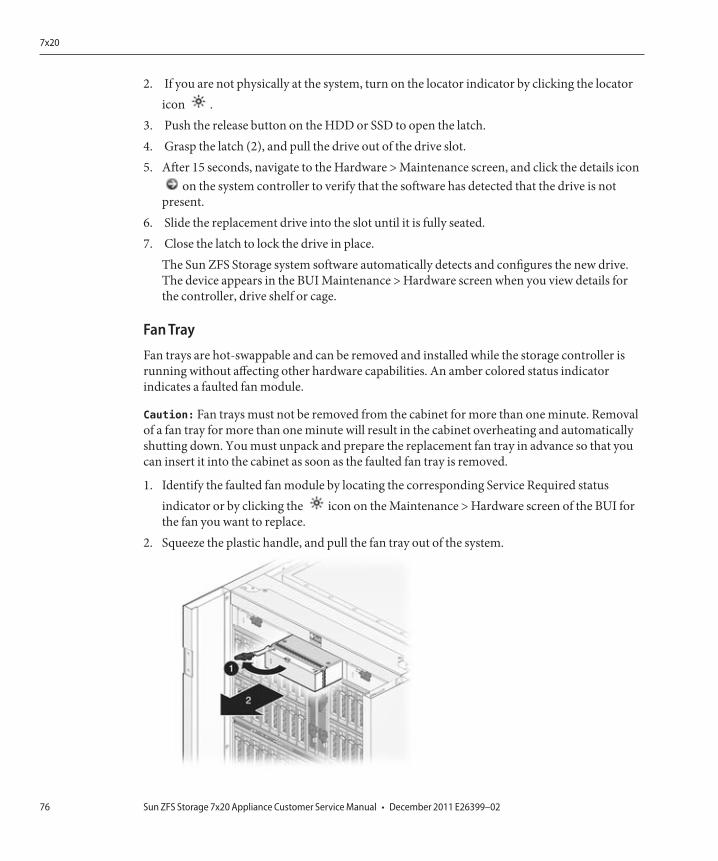
2. If you are not physically at the system, turn on the locator indicator by clicking the locatoricon .
3. Push the release button on the HDD or SSD to open the latch.4. Grasp the latch (2), and pull the drive out of the drive slot.5. After 15 seconds, navigate to the Hardware > Maintenance screen, and click the details icon
on the system controller to verify that the software has detected that the drive is notpresent.
6. Slide the replacement drive into the slot until it is fully seated.7. Close the latch to lock the drive in place.
The Sun ZFS Storage system software automatically detects and configures the new drive.The device appears in the BUI Maintenance > Hardware screen when you view details forthe controller, drive shelf or cage.
Fan Tray
Fan trays are hot-swappable and can be removed and installed while the storage controller isrunning without affecting other hardware capabilities. An amber colored status indicatorindicates a faulted fan module.
Caution: Fan trays must not be removed from the cabinet for more than one minute. Removalof a fan tray for more than one minute will result in the cabinet overheating and automaticallyshutting down. You must unpack and prepare the replacement fan tray in advance so that youcan insert it into the cabinet as soon as the faulted fan tray is removed.
1. Identify the faulted fan module by locating the corresponding Service Required statusindicator or by clicking the icon on the Maintenance > Hardware screen of the BUI forthe fan you want to replace.
2. Squeeze the plastic handle, and pull the fan tray out of the system.
7x20
Sun ZFS Storage 7x20 Appliance Customer Service Manual • December 2011 E26399–0276
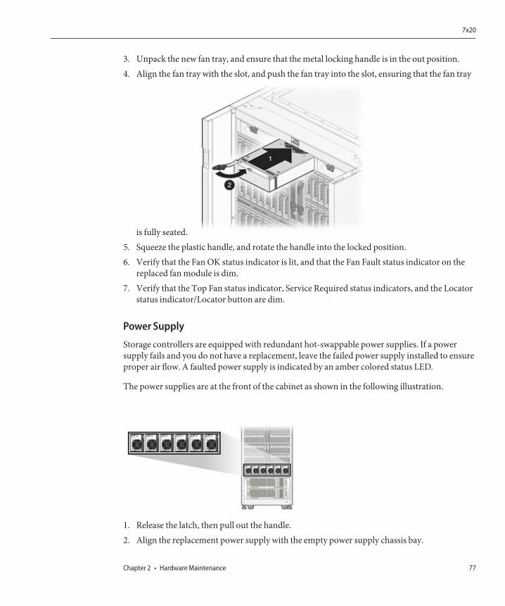
3. Unpack the new fan tray, and ensure that the metal locking handle is in the out position.4. Align the fan tray with the slot, and push the fan tray into the slot, ensuring that the fan tray
is fully seated.5. Squeeze the plastic handle, and rotate the handle into the locked position.6. Verify that the Fan OK status indicator is lit, and that the Fan Fault status indicator on the
replaced fan module is dim.7. Verify that the Top Fan status indicator, Service Required status indicators, and the Locator
status indicator/Locator button are dim.
Power Supply
Storage controllers are equipped with redundant hot-swappable power supplies. If a powersupply fails and you do not have a replacement, leave the failed power supply installed to ensureproper air flow. A faulted power supply is indicated by an amber colored status LED.
The power supplies are at the front of the cabinet as shown in the following illustration.
1. Release the latch, then pull out the handle.2. Align the replacement power supply with the empty power supply chassis bay.
7x20
Chapter 2 • Hardware Maintenance 77
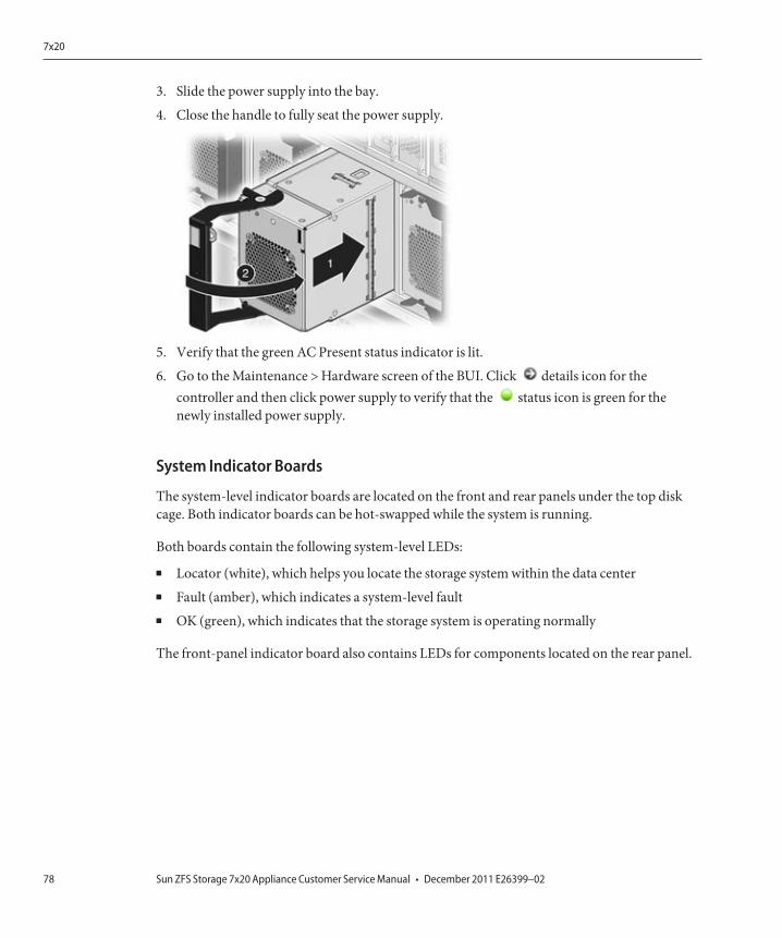
3. Slide the power supply into the bay.
4. Close the handle to fully seat the power supply.
5. Verify that the green AC Present status indicator is lit.
6. Go to the Maintenance > Hardware screen of the BUI. Click details icon for thecontroller and then click power supply to verify that the status icon is green for thenewly installed power supply.
System Indicator Boards
The system-level indicator boards are located on the front and rear panels under the top diskcage. Both indicator boards can be hot-swapped while the system is running.
Both boards contain the following system-level LEDs:
■ Locator (white), which helps you locate the storage system within the data center■ Fault (amber), which indicates a system-level fault■ OK (green), which indicates that the storage system is operating normally
The front-panel indicator board also contains LEDs for components located on the rear panel.
7x20
Sun ZFS Storage 7x20 Appliance Customer Service Manual • December 2011 E26399–0278
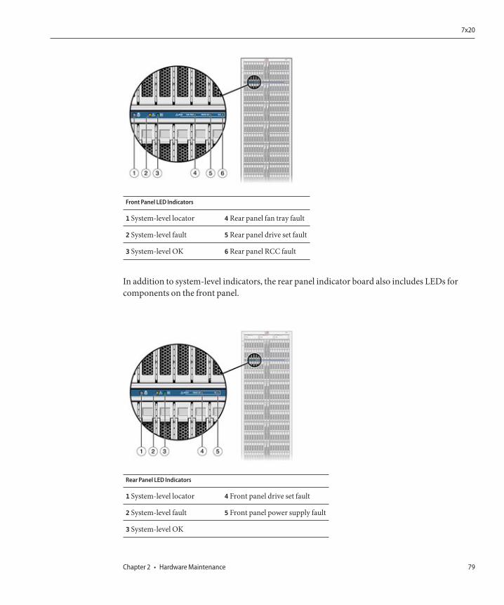
Front Panel LED Indicators
1 System-level locator 4 Rear panel fan tray fault
2 System-level fault 5 Rear panel drive set fault
3 System-level OK 6 Rear panel RCC fault
In addition to system-level indicators, the rear panel indicator board also includes LEDs forcomponents on the front panel.
Rear Panel LED Indicators
1 System-level locator 4 Front panel drive set fault
2 System-level fault 5 Front panel power supply fault
3 System-level OK
7x20
Chapter 2 • Hardware Maintenance 79
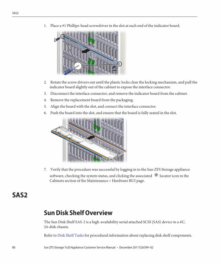
1. Place a #1 Phillips-head screwdriver in the slot at each end of the indicator board.
2. Rotate the screw drivers out until the plastic locks clear the locking mechanism, and pull theindicator board slightly out of the cabinet to expose the interface connector.
3. Disconnect the interface connector, and remove the indicator board from the cabinet.4. Remove the replacement board from the packaging.5. Align the board with the slot, and connect the interface connector.6. Push the board into the slot, and ensure that the board is fully seated in the slot.
7. Verify that the procedure was successful by logging in to the Sun ZFS Storage appliancesoftware, checking the system status, and clicking the associated locator icon in theCabinets section of the Maintenance > Hardware BUI page.
SAS2
Sun Disk Shelf OverviewThe Sun Disk Shelf SAS-2 is a high-availability serial attached SCSI (SAS) device in a 4U,24-disk chassis.
Refer to Disk Shelf Tasks for procedural information about replacing disk shelf components.
SAS2
Sun ZFS Storage 7x20 Appliance Customer Service Manual • December 2011 E26399–0280

The main components are hot-swappable, including the SAS Interface Module (SIM) boardsand drives, and the dual load-sharing power supplies and fans. This provides a fault-tolerantenvironment with no single point of failure. System faults are indicated by an amber coloredlight on the front panel.
Following is the list of replaceable components of the Sun Disk Shelf SAS-2. The SAS-2 (SerialAttached SCSI 2.0) storage fabric supports greater number of targets, greater bandwidth, higherreliability and bigger scale. The scale and reliability improvements are achieved with 2 TB SASdisks you can daisy-chain to a total of 12 shelves (288 total disks). In addition,the new,high-performance SAS-2 HBA is designed for the Sun Storage 7000 series with a standard chipset to support a high-density of target devices, capable of attachment to 1024 targets.
With this new fabric, you are encouraged to apply entire shelves to pools, so you can get thebenefits of No Single Point of Failure (NSPF) configurations and striping across the maximumpossible number of devices.
Part Number Description FRU/CRU
F542-0194-01 SAS Interface Module (SIM) Assembly CRU
F300-2276-01 764W AC Input Power Supply and Fan Assembly CRU
F540-7980-01 Z-box with Backplane (J4410 4U chassis) FRU
F542-0274-01 2TB - 7.2K SAS HDD Assembly CRU
F542-0286-01 SAS 100GB SSD Logzilla CRU
SAS2 Sun Disk Shelf Overview
Power Supply Exterior
Power supplies and fans, SIMs, and disks are hot-pluggable on the storage shelf. The followingfigure shows the exterior of the power supply. Power supply 0 is on the left and power supply 1is on the right.
SAS2
Chapter 2 • Hardware Maintenance 81
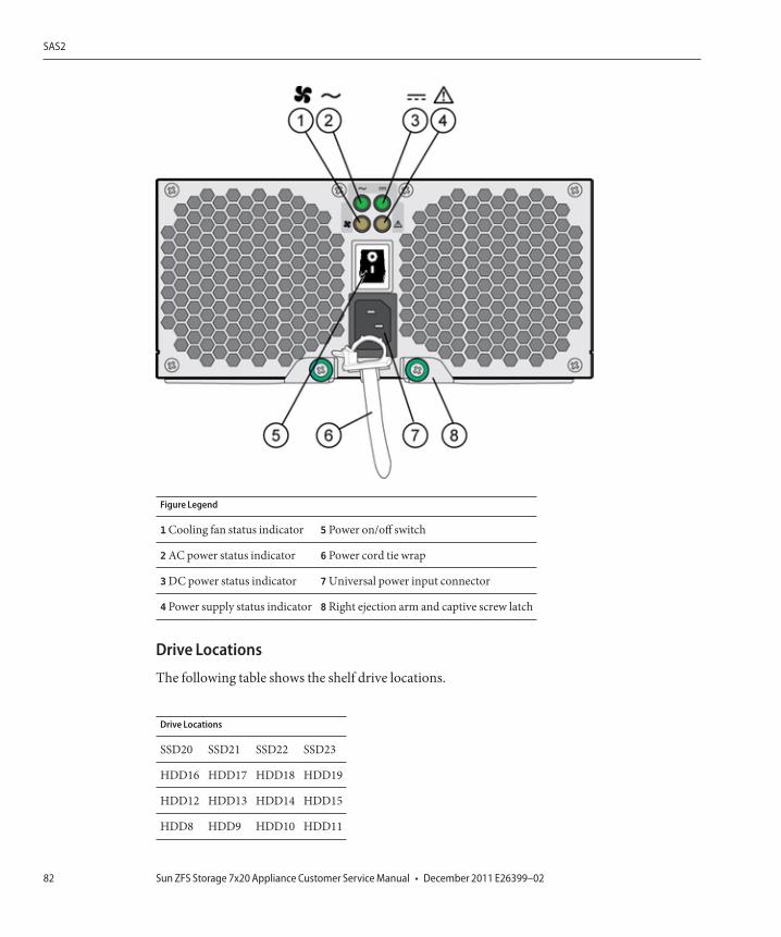
Figure Legend
1 Cooling fan status indicator 5 Power on/off switch
2 AC power status indicator 6 Power cord tie wrap
3 DC power status indicator 7 Universal power input connector
4 Power supply status indicator 8 Right ejection arm and captive screw latch
Drive Locations
The following table shows the shelf drive locations.
Drive Locations
SSD20 SSD21 SSD22 SSD23
HDD16 HDD17 HDD18 HDD19
HDD12 HDD13 HDD14 HDD15
HDD8 HDD9 HDD10 HDD11
SAS2
Sun ZFS Storage 7x20 Appliance Customer Service Manual • December 2011 E26399–0282

Drive Locations
HDD4 HDD5 HDD6 HDD7
HDD0 HDD1 HDD2 HDD3
The following figure shows the Sun Disk Shelf front panel.
Figure Legend
1 Locate button and indicator 4 Disk ready to be removed inidicator 7 Over temperature warning indicator
2 System fault indicator 5 Disk fault indicator 8 SIM board fault indicator
3 System power indicator 6 Disk activity indicator 9 Power supply fault indicator
Sun Disk Shelf Logzilla SSD Locations
Up to four Logzilla SSDs are supported per disk shelf.
Logzilla SSDs should be populated in order of slots 20, 21, 22, and 23.
Drive Assembly ExteriorThe following figure shows the drive assembly exterior for the Sun Disk Shelf.
SAS2
Chapter 2 • Hardware Maintenance 83
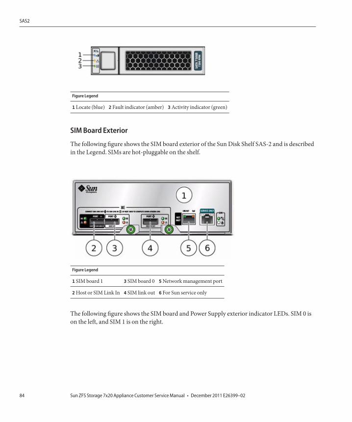
Figure Legend
1 Locate (blue) 2 Fault indicator (amber) 3 Activity indicator (green)
SIM Board Exterior
The following figure shows the SIM board exterior of the Sun Disk Shelf SAS-2 and is describedin the Legend. SIMs are hot-pluggable on the shelf.
Figure Legend
1 SIM board 1 3 SIM board 0 5 Network management port
2 Host or SIM Link In 4 SIM link out 6 For Sun service only
The following figure shows the SIM board and Power Supply exterior indicator LEDs. SIM 0 ison the left, and SIM 1 is on the right.
SAS2
Sun ZFS Storage 7x20 Appliance Customer Service Manual • December 2011 E26399–0284
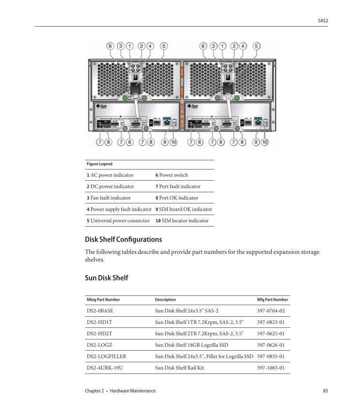
Figure Legend
1 AC power indicator 6 Power switch
2 DC power indicator 7 Port fault indicator
3 Fan fault indicator 8 Port OK indicator
4 Power supply fault indicator 9 SIM board OK indicator
5 Universal power connector 10 SIM locator indicator
Disk Shelf Configurations
The following tables describe and provide part numbers for the supported expansion storageshelves.
Sun Disk Shelf
Mktg Part Number Description Mfg Part Number
DS2-0BASE Sun Disk Shelf 24x3.5" SAS-2 597-0764-02
DS2-HD1T Sun Disk Shelf 1TB 7.2Krpm, SAS-2, 3.5" 597-0823-01
DS2-HD2T Sun Disk Shelf 2TB 7.2Krpm, SAS-2, 3.5" 597-0625-01
DS2-LOGZ Sun Disk Shelf 18GB Logzilla SSD 597-0626-01
DS2-LOGFILLER Sun Disk Shelf 24x3.5", Filler for Logzilla SSD 597-0835-01
DS2-4URK-19U Sun Disk Shelf Rail Kit 597-1083-01
SAS2
Chapter 2 • Hardware Maintenance 85
Mktg Part Number Description Mfg Part Number
DS2X-LOGZ Sun Disk Shelf 18GB Logzilla SSD 594-6629-01
DS2X-4URK-19U Sun Disk Shelf Rail Kit 594-6462-01
Shelf
Disk Shelf Maintenance ProceduresThis section provides procedural details for customer replaceable units (CRUs) of any disk shelfin the Sun ZFS Storage 7000 family of products. Refer to Disk Shelf Overview for componentspecifications and diagrams.
Prerequisites■ Read the information in the overview section for your controller and become familiar with
the replaceable parts of the system:■ 7120 Overview
■ 7420 Overview■ Follow the instructions in the Electrostatic Discharge Precautions section.
Legacy platform overviews are provided in the following sections:
■ 7110■ 7210■ 7310■ 7410■ J4400/J4500 Disk Shelf
Safety InformationFollow all Sun cautions, warnings, and instructions marked on the equipment and described inImportant Safety Information for Sun Hardware Systems located at http://download.oracle.com/docs/cd/E19446-01/en/821-1590-10/821-1590-10.pdf. (http://download.oracle.com/docs/cd/E19446-01/en/821-1590-10/821-1590-10.pdf.)
Shelf
Sun ZFS Storage 7x20 Appliance Customer Service Manual • December 2011 E26399–0286
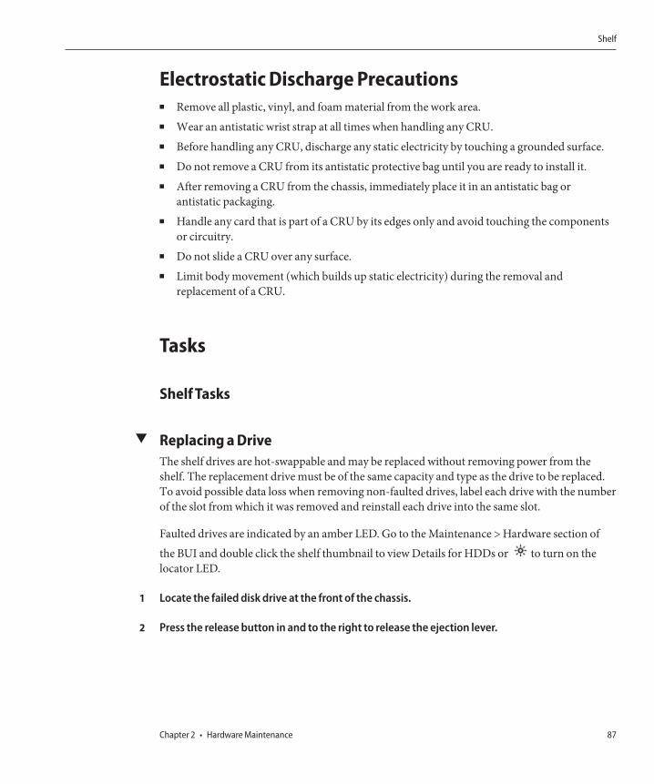
Electrostatic Discharge Precautions■ Remove all plastic, vinyl, and foam material from the work area.■ Wear an antistatic wrist strap at all times when handling any CRU.■ Before handling any CRU, discharge any static electricity by touching a grounded surface.■ Do not remove a CRU from its antistatic protective bag until you are ready to install it.■ After removing a CRU from the chassis, immediately place it in an antistatic bag or
antistatic packaging.■ Handle any card that is part of a CRU by its edges only and avoid touching the components
or circuitry.■ Do not slide a CRU over any surface.■ Limit body movement (which builds up static electricity) during the removal and
replacement of a CRU.
Tasks
Shelf Tasks
▼ Replacing a DriveThe shelf drives are hot-swappable and may be replaced without removing power from theshelf. The replacement drive must be of the same capacity and type as the drive to be replaced.To avoid possible data loss when removing non-faulted drives, label each drive with the numberof the slot from which it was removed and reinstall each drive into the same slot.
Faulted drives are indicated by an amber LED. Go to the Maintenance > Hardware section ofthe BUI and double click the shelf thumbnail to view Details for HDDs or to turn on thelocator LED.
Locate the failed disk drive at the front of the chassis.
Press the release button in and to the right to release the ejection lever.
1
2
Shelf
Chapter 2 • Hardware Maintenance 87
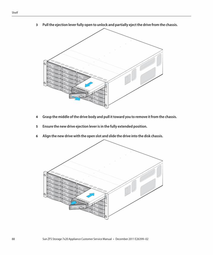
Pull the ejection lever fully open to unlock and partially eject the drive from the chassis.
Grasp the middle of the drive body and pull it toward you to remove it from the chassis.
Ensure the new drive ejection lever is in the fully extended position.
Align the new drive with the open slot and slide the drive into the disk chassis.
3
4
5
6
Shelf
Sun ZFS Storage 7x20 Appliance Customer Service Manual • December 2011 E26399–0288
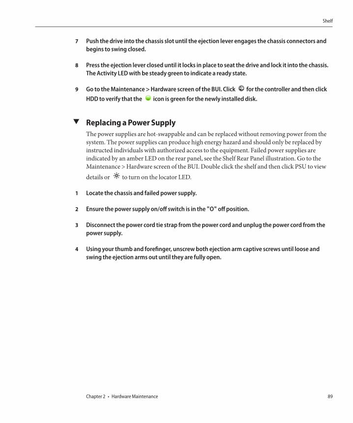
Push the drive into the chassis slot until the ejection lever engages the chassis connectors andbegins to swing closed.
Press the ejection lever closed until it locks in place to seat the drive and lock it into the chassis.The Activity LED with be steady green to indicate a ready state.
Go to the Maintenance > Hardware screen of the BUI. Click for the controller and then clickHDD to verify that the icon is green for the newly installed disk.
▼ Replacing a Power SupplyThe power supplies are hot-swappable and can be replaced without removing power from thesystem. The power supplies can produce high energy hazard and should only be replaced byinstructed individuals with authorized access to the equipment. Failed power supplies areindicated by an amber LED on the rear panel, see the Shelf Rear Panel illustration. Go to theMaintenance > Hardware screen of the BUI. Double click the shelf and then click PSU to viewdetails or to turn on the locator LED.
Locate the chassis and failed power supply.
Ensure the power supply on/off switch is in the "O" off position.
Disconnect the power cord tie strap from the power cord and unplug the power cord from thepower supply.
Using your thumb and forefinger, unscrew both ejection arm captive screws until loose andswing the ejection arms out until they are fully open.
7
8
9
1
2
3
4
Shelf
Chapter 2 • Hardware Maintenance 89
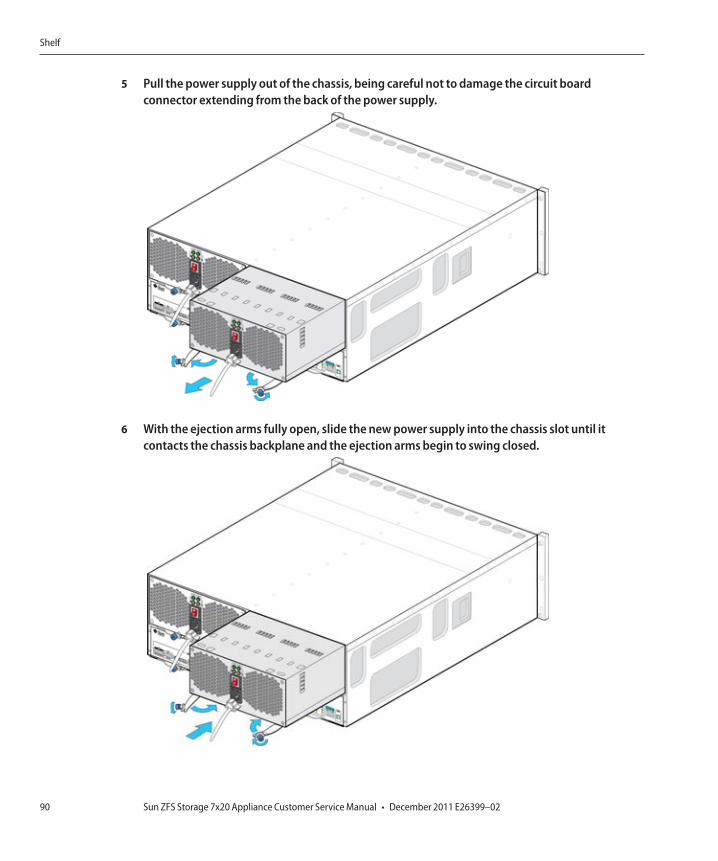
Pull the power supply out of the chassis, being careful not to damage the circuit boardconnector extending from the back of the power supply.
With the ejection arms fully open, slide the new power supply into the chassis slot until itcontacts the chassis backplane and the ejection arms begin to swing closed.
5
6
Shelf
Sun ZFS Storage 7x20 Appliance Customer Service Manual • December 2011 E26399–0290
Push the ejection arms closed fully and secure both captive screws to seat and secure the powersupply in the chassis.
Ensure the power supply on/off switch is in the "O" off position.
Plug the power cord into the new power supply and attach the power cord tie strap to the powercord.
Place the power supply on/off switch to the "I" on position. The Power status LED should be asteady green and the Power status LED and Fan LED should be off.
Go to the Maintenance > Hardware screen of the BUI. Click for the controller and then clickPSU to verify that the icon is green for the newly installed power supply.
▼ Replacing a SIM BoardThe SIM boards are hot-swappable so you can replace them without removing power to thesystem. The SIM boards are multi-pathed, so you can remove one of the SIM boards at anytime, regardless of the state of the blue SIM OK indicator. A faulted SIM board is indicated byan amber LED.
Locate the failed SIM at the back of the disk tray.
Label and disconnect the tray interface cables.
Use two hands to disconnect the SAS cable. Grasp the metal body of the connector with onehand and firmly grasp and pull the tab gently toward the connector body with the other, thenpull the connector body outward to extract it from the bulkhead. Do not twist or pull the tab inany direction other than parallel with the connector body or it may break. If the tab breaks, use asmall sharp object (such as a fine-tipped screwdriver) to lift the metal spring at the top of theconnector shell to unlatch it.
Loosen the two extraction arm captive screws using your thumb and forefinger. If the captivescrews are too tight to loosen by hand, use a No.2 Phillips screwdriver to loosen each screw.
7
8
9
10
11
1
2
3
4
Shelf
Chapter 2 • Hardware Maintenance 91
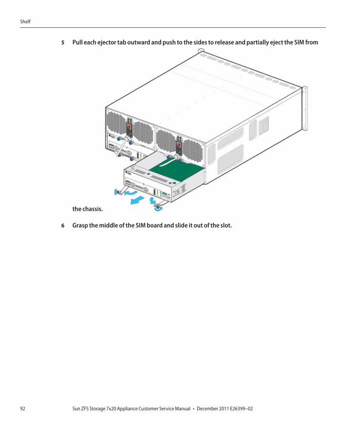
Pull each ejector tab outward and push to the sides to release and partially eject the SIM from
the chassis.
Grasp the middle of the SIM board and slide it out of the slot.
5
6
Shelf
Sun ZFS Storage 7x20 Appliance Customer Service Manual • December 2011 E26399–0292
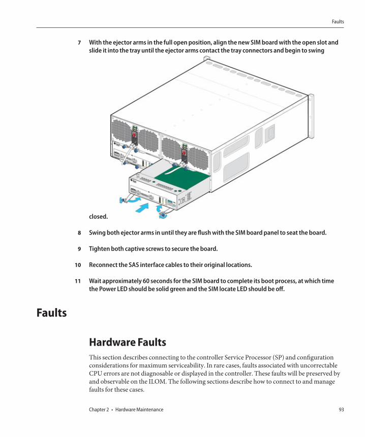
With the ejector arms in the full open position, align the new SIM board with the open slot andslide it into the tray until the ejector arms contact the tray connectors and begin to swing
closed.
Swing both ejector arms in until they are flush with the SIM board panel to seat the board.
Tighten both captive screws to secure the board.
Reconnect the SAS interface cables to their original locations.
Wait approximately 60 seconds for the SIM board to complete its boot process, at which timethe Power LED should be solid green and the SIM locate LED should be off.
Faults
Hardware FaultsThis section describes connecting to the controller Service Processor (SP) and configurationconsiderations for maximum serviceability. In rare cases, faults associated with uncorrectableCPU errors are not diagnosable or displayed in the controller. These faults will be preserved byand observable on the ILOM. The following sections describe how to connect to and managefaults for these cases.
7
8
9
10
11
Faults
Chapter 2 • Hardware Maintenance 93
Connect to ILOMConnect to the server ILOM (Service Processor) on the server platform to diagnose hardwarefaults that do not appear in the BUI.
In a cluster environment, an ILOM connection should be made to each controller.
The server ILOM provides options for (i) network and (ii) serial port connectivity. Networkconnection is the preferred choice, as the ILOM serial port does not always allow adequatemeans of platform data collection.
WARNING : Failure to configure ILOM connectivity may lead to longer than necessary hardwarefault diagnosis and resolution times.
Management Port ConfigurationAll standalone controllers should have at least one NIC port configured as a managementinterface. Select the Allow Admin option in the BUI to enable BUI connections on port 215 andCLI connections on ssh port 22.
All cluster installations should have at least one NIC port on each controller configured as amanagement interface as described above. In addition, the NIC instance number must beunique on each controller. For example, nodeA uses nge0 and nodeB uses nge1, so that neithermay be used as a cluster data interface. In addition, these interfaces must be locked to thecontroller using the Configuration -> Cluster option in the BUI. In some cases, this may requireinstallation of an additional network interface card on each controller in a cluster configuration.
If access to the appliance data interfaces is impossible for any reason, the management networkinterface will maintain BUI and CLI access. During a cluster takeover, interfaces are taken downon the failed controller. So, locked interface configuration is required to gather diagnosticinformation from a failed controller.
WARNING : Failure to configure locked management interfaces on a cluster may lead to longerthan necessary fault diagnosis and resolution times.
Observing and Clearing CPU faults from ILOMLog in to the server as root using the ILOM CLI. To view server faults, type the followingcommand to list all known faults on the system:
-> show /SP/faultmgmt
The server lists all known faults, for example:
SP/faultmgmt
Targets:
0 (/SYS/MB/P0)
Properties:
Faults
Sun ZFS Storage 7x20 Appliance Customer Service Manual • December 2011 E26399–0294
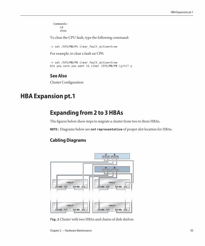
Commands:
cd
show
To clear the CPU fault, type the following command:
-> set /SYS/MB/Pn clear_fault_action=true
For example, to clear a fault on CP0:
-> set /SYS/MB/P0 clear_fault_action=true
Are you sure you want to clear /SYS/MB/P0 (y/n)? y
See AlsoCluster Configuration
HBA Expansion pt.1
Expanding from 2 to 3 HBAsThe figures below show steps to migrate a cluster from two to three HBAs.
NOTE: Diagrams below are not representative of proper slot location for HBAs.
Cabling Diagrams
fig.1 Cluster with two HBAs and chains of disk shelves
HBA Expansion pt.1
Chapter 2 • Hardware Maintenance 95

fig.2 Power down and remove all cabling from the first controller. Add and cable together thenew chain of disk shelves, then power on shelves.
HBA Expansion pt.1
Sun ZFS Storage 7x20 Appliance Customer Service Manual • December 2011 E26399–0296
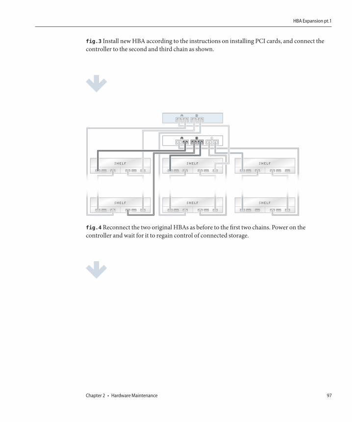
fig.3 Install new HBA according to the instructions on installing PCI cards, and connect thecontroller to the second and third chain as shown.
fig.4 Reconnect the two original HBAs as before to the first two chains. Power on thecontroller and wait for it to regain control of connected storage.
HBA Expansion pt.1
Chapter 2 • Hardware Maintenance 97
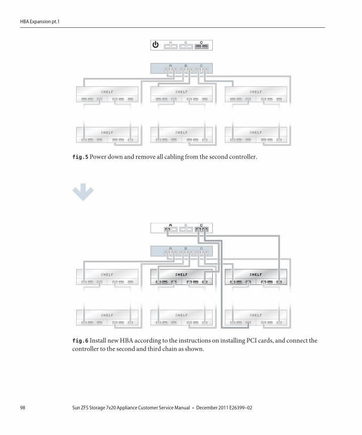
fig.5 Power down and remove all cabling from the second controller.
fig.6 Install new HBA according to the instructions on installing PCI cards, and connect thecontroller to the second and third chain as shown.
HBA Expansion pt.1
Sun ZFS Storage 7x20 Appliance Customer Service Manual • December 2011 E26399–0298
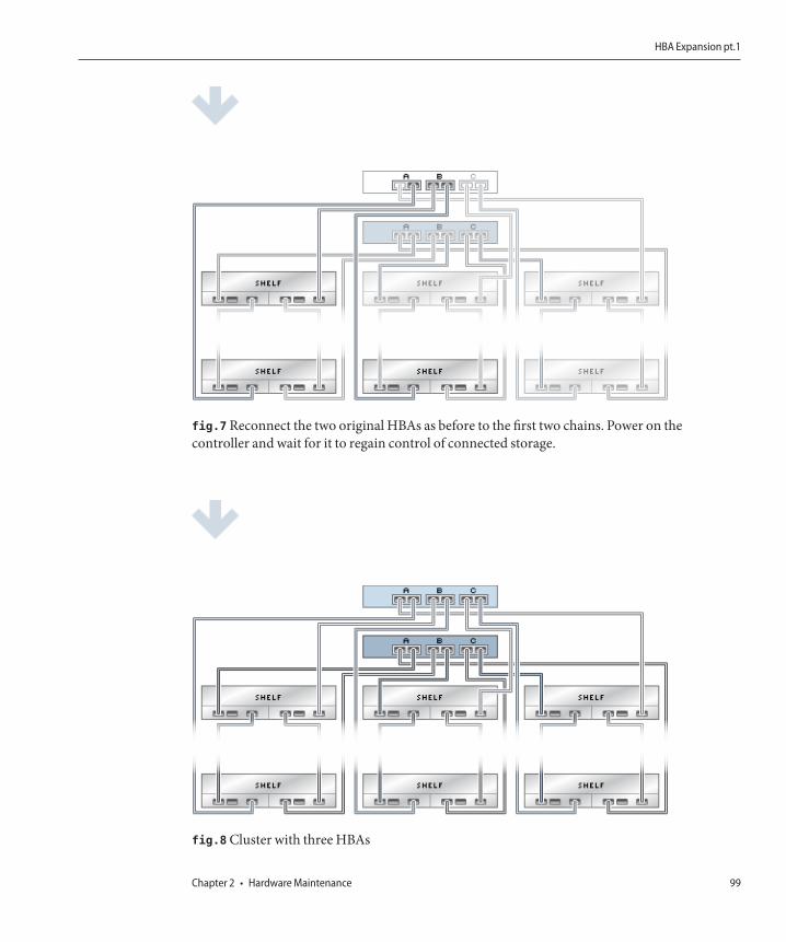
fig.7 Reconnect the two original HBAs as before to the first two chains. Power on thecontroller and wait for it to regain control of connected storage.
fig.8 Cluster with three HBAs
HBA Expansion pt.1
Chapter 2 • Hardware Maintenance 99

HBA Expansion pt.2
Expanding from 3 to 4 HBAsThe figures below show steps to migrate a cluster from three to four HBAs.
NOTE: Diagrams below are not representative of proper slot location for HBAs.
Cabling Diagrams
fig.1 Cluster with three HBAs and chains of disk shelves
HBA Expansion pt.2
Sun ZFS Storage 7x20 Appliance Customer Service Manual • December 2011 E26399–02100

fig.2 Power down and remove all cabling from the first controller. Add and cable together thenew chain of disk shelves, then power on shelves.
fig.3 Install new HBA according to the instructions on installing PCI cards, and connect thecontroller to the third and fourth chain as shown.
HBA Expansion pt.2
Chapter 2 • Hardware Maintenance 101
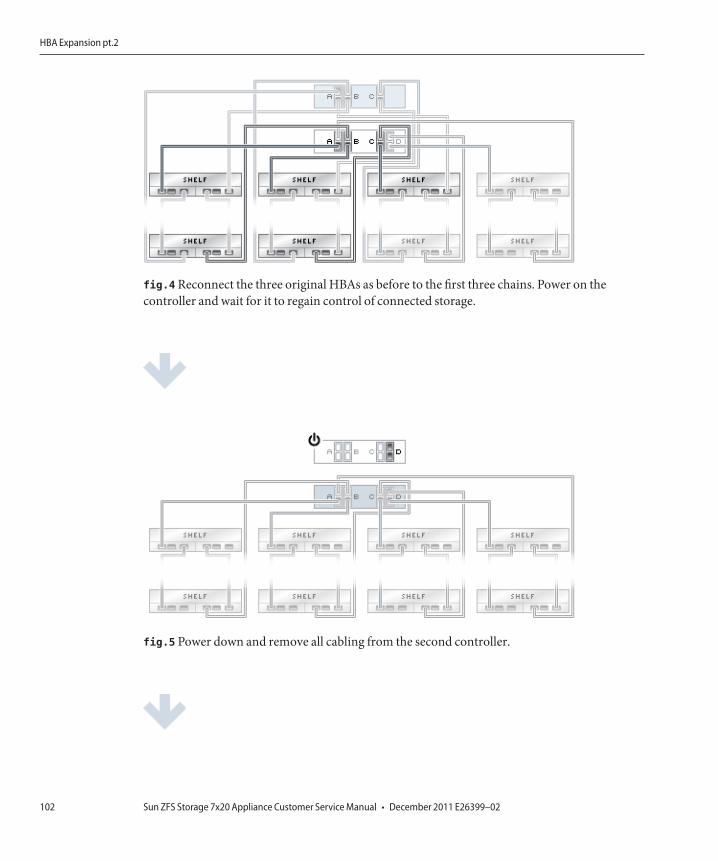
fig.4 Reconnect the three original HBAs as before to the first three chains. Power on thecontroller and wait for it to regain control of connected storage.
fig.5 Power down and remove all cabling from the second controller.
HBA Expansion pt.2
Sun ZFS Storage 7x20 Appliance Customer Service Manual • December 2011 E26399–02102
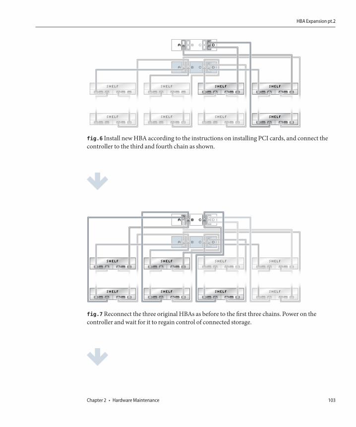
fig.6 Install new HBA according to the instructions on installing PCI cards, and connect thecontroller to the third and fourth chain as shown.
fig.7 Reconnect the three original HBAs as before to the first three chains. Power on thecontroller and wait for it to regain control of connected storage.
HBA Expansion pt.2
Chapter 2 • Hardware Maintenance 103

fig.8 Cluster with four HBAs
HBA Expansion pt.2
Sun ZFS Storage 7x20 Appliance Customer Service Manual • December 2011 E26399–02104
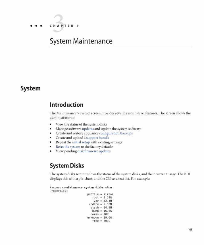
System Maintenance
System
IntroductionThe Maintenance > System screen provides several system-level features. The screen allows theadministrator to:■ View the status of the system disks■ Manage software updates and update the system software■ Create and restore appliance configuration backups■ Create and upload a support bundle■ Repeat the initial setup with existing settings■ Reset the system to the factory defaults■ View pending disk firmware updates
System DisksThe system disks section shows the status of the system disks, and their current usage. The BUIdisplays this with a pie-chart, and the CLI as a text list. For example:
tarpon:> maintenance system disks show
Properties:
profile = mirror
root = 1.14G
var = 52.4M
update = 2.52M
stash = 14.8M
dump = 16.0G
cores = 18K
unknown = 39.0G
free = 401G
3C H A P T E R 3
105
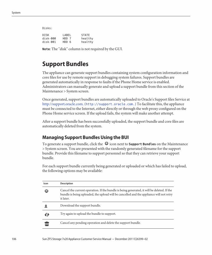
Disks:
DISK LABEL STATE
disk-000 HDD 7 healthy
disk-001 HDD 6 healthy
Note: The "disk" column is not required by the GUI.
Support BundlesThe appliance can generate support bundles containing system configuration information andcore files for use by remote support in debugging system failures. Support bundles aregenerated automatically in response to faults if the Phone Home service is enabled.Administrators can manually generate and upload a support bundle from this section of theMaintenance > System screen.
Once generated, support bundles are automatically uploaded to Oracle's Support files Service athttp://support.oracle.com. (http://support.oracle.com.) To facilitate this, the appliancemust be connected to the Internet, either directly or through the web proxy configured on thePhone Home service screen. If the upload fails, the system will make another attempt.
After a support bundle has been successfully uploaded, the support bundle and core files areautomatically deleted from the system.
Managing Support Bundles Using the BUITo generate a support bundle, click the icon next to Support Bundles on the Maintenance> System screen. You are presented with the randomly generated filename for the supportbundle. Provide this filename to support personnel so that they can retrieve your supportbundle.
For each support bundle currently being generated or uploaded or which has failed to upload,the following options may be available:
Icon Description
Cancel the current operation. If the bundle is being generated, it will be deleted. If thebundle is being uploaded, the upload will be cancelled and the appliance will not retryit later.
Download the support bundle.
Try again to upload the bundle to support.
Cancel any pending operation and delete the support bundle.
System
Sun ZFS Storage 7x20 Appliance Customer Service Manual • December 2011 E26399–02106

Managing Support Bundles Using the CLITo generate and upload a new support bundle, use the sendbundle command:
loader:> maintenance system
loader:maintenance system> sendbundle
A support bundle is being created and sent to Oracle. You will receive an alert
when the bundle has finished uploading. Please save the following filename, as
Oracle support personnel will need it in order to access the bundle:
/cores/ak.9a4c3d7b-50c5-6eb9-c2a6-ec9808ae1cd8.tar.gz
As the message indicates, you must provide this filename to support personnel in order forthem to retrieve your bundle.
Manage bundles from the maintenance system bundles context in the CLI, as follows:
loader:maintenance system> bundles
loader:maintenance system bundles> list
BUNDLE STATUS PROGRESS
/cores/ak.9a4c3d7b-50c5-6eb9-c2a6-ec9808ae1cd8.tar.gz Uploading 7%
loader:maintenance system bundles>
Bundles are identified by the filename, omitting the ak. prefix and the file type suffix. To deletea support bundle, use the destroy command. To view details, use the select and list
commands:
loader:maintenance system bundles> select 9a4c3d7b-50c5-6eb9-c2a6-ec9808ae1cd8
loader:maintenance system bundles 9a4c3d7b-50c5-6eb9-c2a6-ec9808ae1cd8> list
Properties:
filename = /cores/ak.9a4c3d7b-50c5-6eb9-c2a6-ec9808ae1cd8.tar.gz
status = uploading
step_progress = 14.709744730821669
These read-only properties indicate that the appliance is 14% of the way through uploading thefile. To retry a failed upload or cancel a pending operation, enter the retry and cancel
commands respectively.
Initial SetupInitial setup will step through the tasks performed as part of the initial configuration. This willnot change any of the current settings unless explicitly requested. User data on the storage pool(including projects and shares) will not be affected.
To perform an initial setup:
■ BUI: click the "INITIAL SETUP" button on the Maintenance > System screen.■ CLI: enter the maintenance system context, then enter the setup command.
System
Chapter 3 • System Maintenance 107
Factory ResetFactory reset will reset the appliance configuration back to factory settings of the currentsoftware version, and reboot the appliance. All configuration changes will be lost, and theappliance will need to go through initial configuration again, as when it was first installed. Userdata on the storage pool (including projects and shares) will not be affected - however the poolwill need to be imported as part of the initial setup process.
To perform a factory reset:
■ BUI: click the "FACTORY RESET" button on the Maintenance > System screen.■ CLI: enter the maintenance system context, then issue the factoryreset command.■ GRUB: Add -c to the GRUB menu on the line beginning with kernel.
Note: Factory reset of a single controller while configured into a cluster is not supported. Thecontroller must be unclustered first.
Updates
System UpdatesThe system update feature provides customers, developers, and field personnel with the abilityto update a system's software after the system is installed.
Software updates are delivered as opaque binary downloads that contain some or all of:
■ Management and system software.■ Firmware for internal components such as HBAs and network devices.■ Firmware for disks and flash devices.■ Firmware for external storage enclosure components.
In general, the update release notes describe what is in the update, and the update processautomates all of the steps of activating the delivered components.
ProcedureThe procedure for updating the system is as follows:
■ First, the software update media is downloaded from an Oracle support website or retrievedfrom another official source. The media is represented by a single compressed file namedafter the version number, such as: ak-nas-2010-02-09-1-0.pkg.gz. The file can be renamed ifneeded, as the true version number is recorded internally within the image. The compressedmedia packages will vary in size, but typically will be on the order of several hundredmegabytes.
Updates
Sun ZFS Storage 7x20 Appliance Customer Service Manual • December 2011 E26399–02108

■ Second, the software media is uploaded to the appliance. This can be done via either the BUIor the CLI; see below for details of this operation.
■ After the media is uploaded, it will be unpacked and verified. If all verification checks pass, itwill appear in the list of update images as eligible for installation. Any number of images canbe maintained on the appliance, subject to a system disk space quota, without actuallyapplying them. If an update has not yet been applied (i.e. is not running and is not a rollbacktarget), it can be deleted via either the BUI or the CLI. You might want to delete images inorder to free up needed space to download new images.
■ Administrators should verify that the system is in a healthy state prior to applying theupdate. The details are described below in the preconditions section.
■ After the media is unpacked and verified, the update can be applied. You may be asked to setupdate options and confirm. For more information on these questions, see the section ondeferred updates. If the update is no longer appropriate for the system (because you haveskipped past its version number), an error message may be provided. During the update,messages and a progress meter will appear to indicate that the update is proceeding. Theinstallation portion of the update will take about half an hour to complete; however, the fullupgrade process may not be complete at that point. See below regarding additional firmwareupgrades that may take place following the reboot.
■ While the upgrade is in progress, up until the reboot and following the reboot during anyfirmware upgrades, it is non-disruptive: the controller continues to provide data servicesto clients. If the system software fails during the upgrade, it will reboot and continuerunning the software from before the upgrade. Important: Do not perform a clustertakeover operation or a reboot while an upgrade is in progress.
■ Following the post-upgrade reboot, component firmware will be updated (see firmwareupdates below) which will take additional time that depends on the size of the systemconfiguration and the amount of firmware that has changed since the previously-installedversion was delivered; very large Sun Storage 7410 configurations may take several hours tocomplete all firmware upgrades once the update itself has been applied.
PreconditionsBest practices include verifying several preconditions prior to applying an update. Wheneverpossible, administrators should ensure that these preconditions are satisfied immediately priorto applying an update on the storage controller. In a clustered environment, these should beverified on both storage controllers before applying the update to either one.
■ Ensure that any resilvering operations have completed. This can be observed inConfiguration/Storage or the equivalent CLI context.
■ Ensure that there are no active problems.
■ Verify that firmware updates are not in progress.
Updates
Chapter 3 • System Maintenance 109
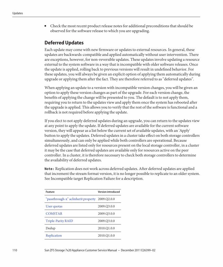
■ Check the most recent product release notes for additional preconditions that should beobserved for the software release to which you are upgrading.
Deferred UpdatesEach update may come with new firmware or updates to external resources. In general, theseupdates are backwards-compatible and applied automatically without user intervention. Thereare exceptions, however, for non-reversible updates. These updates involve updating a resourceexternal to the system software in a way that is incompatible with older software releases. Oncethe update is applied, rolling back to previous versions will result in undefined behavior. Forthese updates, you will always be given an explicit option of applying them automatically duringupgrade or applying them after the fact. They are therefore referred to as "deferred updates".
When applying an update to a version with incompatible version changes, you will be given anoption to apply these version changes as part of the upgrade. For each version change, thebenefits of applying the change will be presented to you. The default is to not apply them,requiring you to return to the updates view and apply them once the system has rebooted afterthe upgrade is applied. This allows you to verify that the rest of the software is functional and arollback is not required before applying the update.
If you elect to not apply deferred updates during an upgrade, you can return to the updates viewat any point to apply the update. If deferred updates are available for the current softwareversion, they will appear as a list below the current set of available updates, with an 'Apply'button to apply the updates. Deferred updates in a cluster take effect on both storage controllerssimultaneously, and can only be applied while both controllers are operational. Becausedeferred updates are listed only for resources present on the local storage controller, in a clusterit may be the case that deferred updates are available only for resources active on the peercontroller. In a cluster, it is therefore necessary to check both storage controllers to determinethe availability of deferred updates.
Note: Replication does not work across deferred updates. After deferred updates are appliedthat increment the stream format version, it is no longer possible to replicate to an older system.See Incompatible target Replication Failure for a description.
Feature Version introduced
"passthrough-x" aclinherit property 2009.Q2.0.0
User quotas 2009.Q3.0.0
COMSTAR 2009.Q3.0.0
Triple-Parity RAID 2009.Q3.0.0
Dedup 2010.Q1.0.0
Replication 2010.Q1.0.0
Updates
Sun ZFS Storage 7x20 Appliance Customer Service Manual • December 2011 E26399–02110
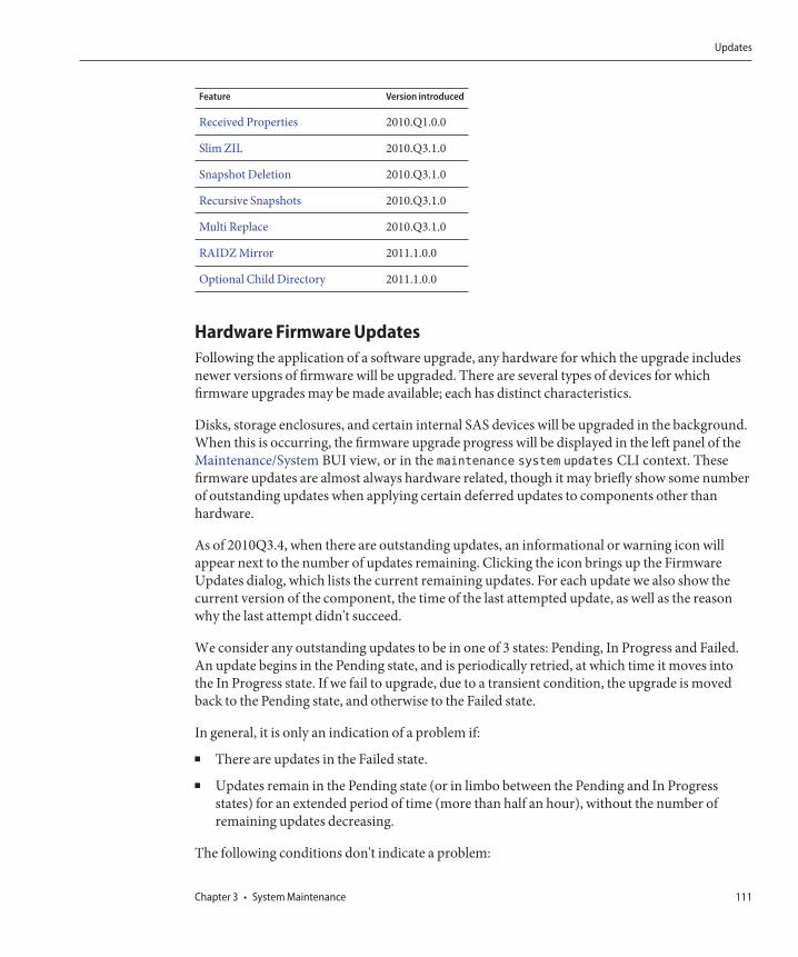
Feature Version introduced
Received Properties 2010.Q1.0.0
Slim ZIL 2010.Q3.1.0
Snapshot Deletion 2010.Q3.1.0
Recursive Snapshots 2010.Q3.1.0
Multi Replace 2010.Q3.1.0
RAIDZ Mirror 2011.1.0.0
Optional Child Directory 2011.1.0.0
Hardware Firmware UpdatesFollowing the application of a software upgrade, any hardware for which the upgrade includesnewer versions of firmware will be upgraded. There are several types of devices for whichfirmware upgrades may be made available; each has distinct characteristics.
Disks, storage enclosures, and certain internal SAS devices will be upgraded in the background.When this is occurring, the firmware upgrade progress will be displayed in the left panel of theMaintenance/System BUI view, or in the maintenance system updates CLI context. Thesefirmware updates are almost always hardware related, though it may briefly show some numberof outstanding updates when applying certain deferred updates to components other thanhardware.
As of 2010Q3.4, when there are outstanding updates, an informational or warning icon willappear next to the number of updates remaining. Clicking the icon brings up the FirmwareUpdates dialog, which lists the current remaining updates. For each update we also show thecurrent version of the component, the time of the last attempted update, as well as the reasonwhy the last attempt didn't succeed.
We consider any outstanding updates to be in one of 3 states: Pending, In Progress and Failed.An update begins in the Pending state, and is periodically retried, at which time it moves intothe In Progress state. If we fail to upgrade, due to a transient condition, the upgrade is movedback to the Pending state, and otherwise to the Failed state.
In general, it is only an indication of a problem if:
■ There are updates in the Failed state.
■ Updates remain in the Pending state (or in limbo between the Pending and In Progressstates) for an extended period of time (more than half an hour), without the number ofremaining updates decreasing.
The following conditions don't indicate a problem:
Updates
Chapter 3 • System Maintenance 111
■ Disks firmware updates are shown as pending for extended periods of time, with a statusmessage indicating that they are not part of any pool. This is expected, given that we onlyupdate disk firmware, for disks that are part of a pool. In order to update these disks, addthem to a pool.
■ There are multiple chassis being updated, we are making progress (the number of remainingupdates decreases), and some of the chassis transiently appear pending with a statusindicating that some disk has only one path. This is also expected, since when we update achassis, we may reset one of its expanders. Resetting an expander causes some disks totemporarily have only one path, and as a result, upgrades to other chassis will be held backuntil it is safe to do so again non-disruptively.
Note that currently the Firmware Updates dialog doesn't automatically refresh, so you wouldhave to close it and re-open it to get an updated view.
Applying hardware updates is always done in a completely safe manner. This means that thesystem may be in a state where hardware updates cannot be applied. This is particularlyimportant in the context of clustered configurations. During takeover and failback operations,any in-progress firmware upgrade will be completed; pending firmware upgrades will besuspended until the takeover or failback has completed, at which time the restrictions describedbelow will be reevaluated in the context of the new cluster state and, if possible, firmwareupgrades will resume. Important: Unless absolutely necessary, takeover and failbackoperations should not be performed while firmware upgrades are in progress. The rollingupgrade procedure documented below meets all of these best practices and addresses theper-device-class restrictions described below. It should always be followed when performingupgrades in a clustered environment. In both clustered and standalone environments, thesecriteria will also be reevaluated upon any reboot or diagnostic system software restart, whichmay cause previously suspended or incomplete firmware upgrades to resume.
■ Components internal to the storage controller (such as HBAs and network devices) otherthan disks and certain SAS devices will generally be upgraded automatically during boot;these upgrades are not visible and will have completed by the time the managementinterfaces become available.
■ Upgrading disk or flash device firmware requires that the device be taken offline during theprocess. If there is insufficient redundancy in the containing storage pool to allow thisoperation, the firmware upgrade will not complete and may appear "stalled." Disks and flashdevices that are part of a storage pool which is currently in use by the cluster peer, if any, willnot be upgraded. Finally, disks and flash devices that are not part of any storage pool will notbe upgraded.
■ Upgrading the firmware in a disk shelf requires that both back-end storage paths be active toall disks within all enclosures, and for storage to be configured on all shelves to be upgraded.For clusters with at least one active pool on each controller, these restrictions mean that diskshelf firmware upgrade can be performed only a controller that is in the "owner" state.
Updates
Sun ZFS Storage 7x20 Appliance Customer Service Manual • December 2011 E26399–02112
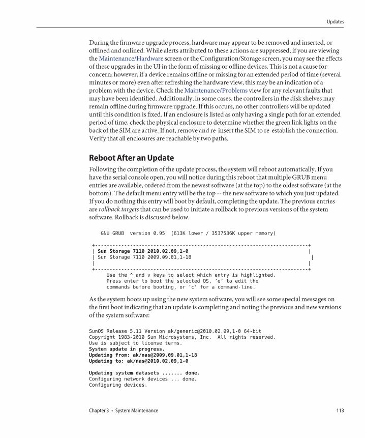
During the firmware upgrade process, hardware may appear to be removed and inserted, orofflined and onlined. While alerts attributed to these actions are suppressed, if you are viewingthe Maintenance/Hardware screen or the Configuration/Storage screen, you may see the effectsof these upgrades in the UI in the form of missing or offline devices. This is not a cause forconcern; however, if a device remains offline or missing for an extended period of time (severalminutes or more) even after refreshing the hardware view, this may be an indication of aproblem with the device. Check the Maintenance/Problems view for any relevant faults thatmay have been identified. Additionally, in some cases, the controllers in the disk shelves mayremain offline during firmware upgrade. If this occurs, no other controllers will be updateduntil this condition is fixed. If an enclosure is listed as only having a single path for an extendedperiod of time, check the physical enclosure to determine whether the green link lights on theback of the SIM are active. If not, remove and re-insert the SIM to re-establish the connection.Verify that all enclosures are reachable by two paths.
Reboot After an UpdateFollowing the completion of the update process, the system will reboot automatically. If youhave the serial console open, you will notice during this reboot that multiple GRUB menuentries are available, ordered from the newest software (at the top) to the oldest software (at thebottom). The default menu entry will be the top -- the new software to which you just updated.If you do nothing this entry will boot by default, completing the update. The previous entriesare rollback targets that can be used to initiate a rollback to previous versions of the systemsoftware. Rollback is discussed below.
GNU GRUB version 0.95 (613K lower / 3537536K upper memory)
+-------------------------------------------------------------------------+
| Sun Storage 7110 2010.02.09,1-0 |
| Sun Storage 7110 2009.09.01,1-18 |
| |
+-------------------------------------------------------------------------+
Use the ^ and v keys to select which entry is highlighted.
Press enter to boot the selected OS, ’e’ to edit the
commands before booting, or ’c’ for a command-line.
As the system boots up using the new system software, you will see some special messages onthe first boot indicating that an update is completing and noting the previous and new versionsof the system software:
SunOS Release 5.11 Version ak/[email protected],1-0 64-bit
Copyright 1983-2010 Sun Microsystems, Inc. All rights reserved.
Use is subject to license terms.
System update in progress.
Updating from: ak/[email protected],1-18
Updating to: ak/[email protected],1-0
Updating system datasets ....... done.
Configuring network devices ... done.
Configuring devices.
Updates
Chapter 3 • System Maintenance 113
Sun Storage 7110 Version ak/[email protected],1-0
Copyright 2010 Sun Microsystems, Inc. All rights reserved.
Use is subject to license terms.
Reading ZFS config: done.
Mounting ZFS filesystems: (27/27)
monk console login:
RollbackThe rollback procedure reverts all of the system software and all of the metadata settings of thesystem back to their state just prior to applying an update. This feature is implemented bytaking a snapshot of various aspects of the system before the new update is applied, and rollingback this snapshot to implement the rollback. The implications of rollback are as follows:■ Any appliance configuration changes are reverted and lost. For example, assume you are
running version V, and then you update to V+1, and then you change your DNS server. Ifyou execute a rollback, then your DNS server setting modification is effectively undone andremoved from the system permanently.
■ Conversely, any changes made to user data are not reverted: if you update from V to V+1,and clients then create directories or modify shares in any way, those changes still exist afterthe rollback (as you would expect).
■ If the appliance is running version V, and has previous rollback targets V-1 and V-2, andyou revert all the way to version V-2 (thereby "skipping" V-1), then you not only areremoving the system software settings and system software for V, but also for V-1. That is,after a rollback to V-2, it is as if updates V-1 and V never happened. However, the softwareupload images for V-1 and V will still be saved on the system and you can apply them againafter the rollback if you wish by re-executing the update.
If after applying an update, the system is back up and running, you can use either the BUI or theCLI to initiate a rollback to one of two previously applied updates. If the system is not able torun at all after an update, then use the fail-safe rollback procedure.
Fail-safe RollbackAdministrators can execute a fail-safe rollback of the system software from the serial console byselecting one of the other boot menu entries, if present. Although rollback can also be requestedfrom the BUI or CLI, rollback is offered from the boot menu because it is possible that rollbackwill be needed in scenarios where the new system software has completely failed, i.e. has failedto even boot. To rollback from the console, access the serial console as usual, and during boot,before the ten second timeout, use the arrow key to move the menu selection down to one of theearlier entries:
GNU GRUB version 0.95 (613K lower / 3537536K upper memory)
+-------------------------------------------------------------------------+
Updates
Sun ZFS Storage 7x20 Appliance Customer Service Manual • December 2011 E26399–02114
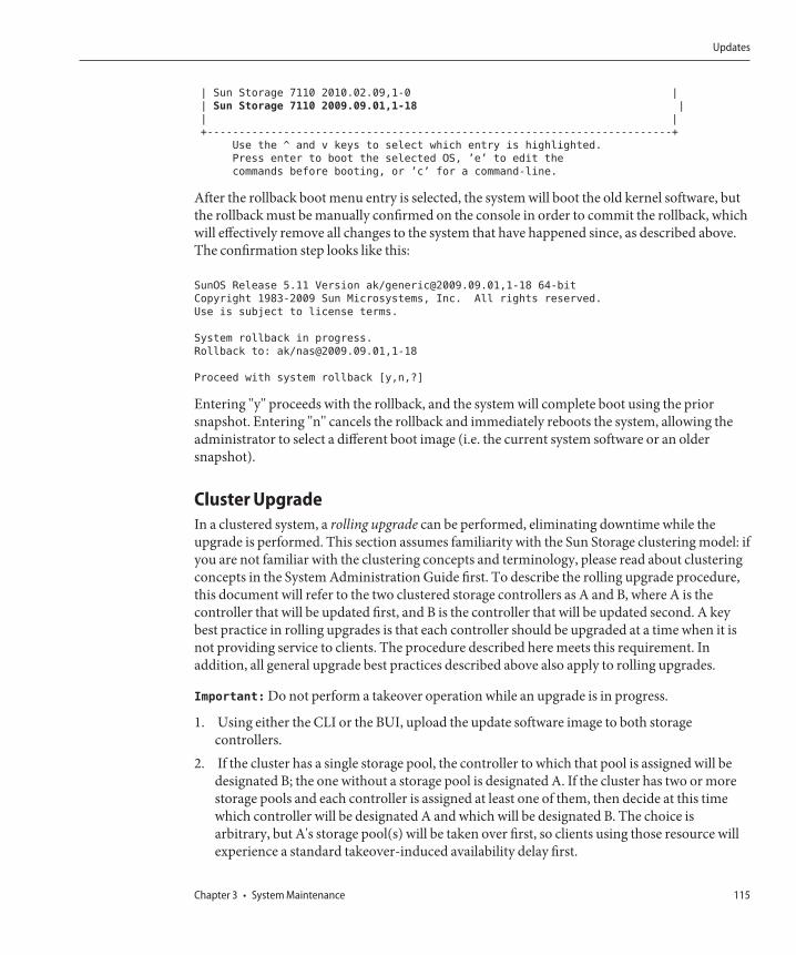
| Sun Storage 7110 2010.02.09,1-0 |
| Sun Storage 7110 2009.09.01,1-18 |
| |
+-------------------------------------------------------------------------+
Use the ^ and v keys to select which entry is highlighted.
Press enter to boot the selected OS, ’e’ to edit the
commands before booting, or ’c’ for a command-line.
After the rollback boot menu entry is selected, the system will boot the old kernel software, butthe rollback must be manually confirmed on the console in order to commit the rollback, whichwill effectively remove all changes to the system that have happened since, as described above.The confirmation step looks like this:
SunOS Release 5.11 Version ak/[email protected],1-18 64-bit
Copyright 1983-2009 Sun Microsystems, Inc. All rights reserved.
Use is subject to license terms.
System rollback in progress.
Rollback to: ak/[email protected],1-18
Proceed with system rollback [y,n,?]
Entering "y" proceeds with the rollback, and the system will complete boot using the priorsnapshot. Entering "n" cancels the rollback and immediately reboots the system, allowing theadministrator to select a different boot image (i.e. the current system software or an oldersnapshot).
Cluster UpgradeIn a clustered system, a rolling upgrade can be performed, eliminating downtime while theupgrade is performed. This section assumes familiarity with the Sun Storage clustering model: ifyou are not familiar with the clustering concepts and terminology, please read about clusteringconcepts in the System Administration Guide first. To describe the rolling upgrade procedure,this document will refer to the two clustered storage controllers as A and B, where A is thecontroller that will be updated first, and B is the controller that will be updated second. A keybest practice in rolling upgrades is that each controller should be upgraded at a time when it isnot providing service to clients. The procedure described here meets this requirement. Inaddition, all general upgrade best practices described above also apply to rolling upgrades.
Important: Do not perform a takeover operation while an upgrade is in progress.
1. Using either the CLI or the BUI, upload the update software image to both storagecontrollers.
2. If the cluster has a single storage pool, the controller to which that pool is assigned will bedesignated B; the one without a storage pool is designated A. If the cluster has two or morestorage pools and each controller is assigned at least one of them, then decide at this timewhich controller will be designated A and which will be designated B. The choice isarbitrary, but A's storage pool(s) will be taken over first, so clients using those resource willexperience a standard takeover-induced availability delay first.
Updates
Chapter 3 • System Maintenance 115
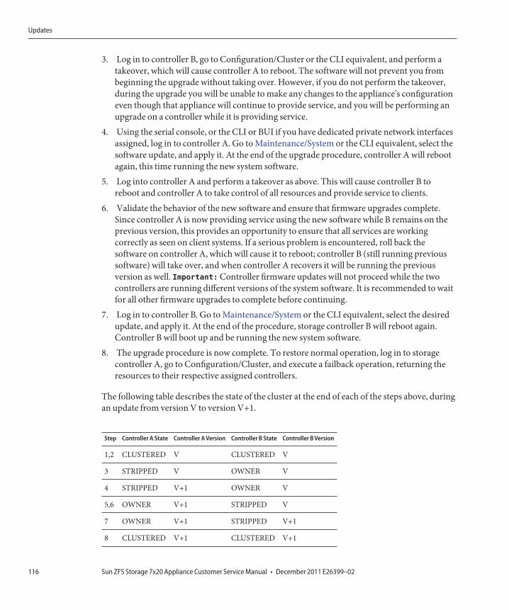
3. Log in to controller B, go to Configuration/Cluster or the CLI equivalent, and perform atakeover, which will cause controller A to reboot. The software will not prevent you frombeginning the upgrade without taking over. However, if you do not perform the takeover,during the upgrade you will be unable to make any changes to the appliance's configurationeven though that appliance will continue to provide service, and you will be performing anupgrade on a controller while it is providing service.
4. Using the serial console, or the CLI or BUI if you have dedicated private network interfacesassigned, log in to controller A. Go to Maintenance/System or the CLI equivalent, select thesoftware update, and apply it. At the end of the upgrade procedure, controller A will rebootagain, this time running the new system software.
5. Log into controller A and perform a takeover as above. This will cause controller B toreboot and controller A to take control of all resources and provide service to clients.
6. Validate the behavior of the new software and ensure that firmware upgrades complete.Since controller A is now providing service using the new software while B remains on theprevious version, this provides an opportunity to ensure that all services are workingcorrectly as seen on client systems. If a serious problem is encountered, roll back thesoftware on controller A, which will cause it to reboot; controller B (still running previoussoftware) will take over, and when controller A recovers it will be running the previousversion as well. Important: Controller firmware updates will not proceed while the twocontrollers are running different versions of the system software. It is recommended to waitfor all other firmware upgrades to complete before continuing.
7. Log in to controller B. Go to Maintenance/System or the CLI equivalent, select the desiredupdate, and apply it. At the end of the procedure, storage controller B will reboot again.Controller B will boot up and be running the new system software.
8. The upgrade procedure is now complete. To restore normal operation, log in to storagecontroller A, go to Configuration/Cluster, and execute a failback operation, returning theresources to their respective assigned controllers.
The following table describes the state of the cluster at the end of each of the steps above, duringan update from version V to version V+1.
Step Controller A State Controller A Version Controller B State Controller B Version
1,2 CLUSTERED V CLUSTERED V
3 STRIPPED V OWNER V
4 STRIPPED V+1 OWNER V
5,6 OWNER V+1 STRIPPED V
7 OWNER V+1 STRIPPED V+1
8 CLUSTERED V+1 CLUSTERED V+1
Updates
Sun ZFS Storage 7x20 Appliance Customer Service Manual • December 2011 E26399–02116
It is not advisable to make configuration changes to either storage controller
while an upgrade is in progress. Most notably, while controllers are running differentsoftware versions, configuration changes made to one controller will not be propagated to itspeer controller. For instance, suppose a change is made to controller A at step 4 above. Thatchange will not be propagated to controller B until step 7, when both controllers areagain running the same software version. Alternatively, if validation of controller A during step6 uncovered a problem that necessitated controller A be rolled back to version V, then thechanges made at step 4 would be also be undone as part of the rollback.
Accordingly, accessing the BUI or logging into the CLI while controllers are running differentsoftware versions will display a warning that configuration changes will not be propagated.Similarly, the appliance can be configured to generate alerts when a cluster is comprised ofcontrollers running different software versions (events "Cluster rejoin mismatch" and "Clusterrejoin mismatch on peer").
If you upgrade, change the root password, and then rollback in a cluster, the nodes will not beable to re-join after the rollback.
Update Health ChecksThe ZFS Storage Appliance update subsystem provides integrated system level health checks tohelp ensure that there are no pathologies that will interfere with the system software update andfirmware upgrade processes. If a problem is found, the update process will be aborted and youwill be directed to the Alert Log for any problems encountered. System software updates willnot be permitted until the problems have been corrected. The system software Release Notes forthe target update media contain a list of all update problems and the procedures used to correctthem.
Ahead of any planned update, the same health checks may be run by applying the update checkfrom the BUI or CLI. This allows you to check the state of the system prior to scheduling anupdate maintenance window and correct any problems that would interfere with the updateprocess. As with the integrated health checks, you will be presented with a link to the Alert Logwhen problems are found. Otherwise, the System Ready state transitions to Yes to indicate thatthe system is in an acceptably healthy state for software updates. The Release Notes for thetarget media contain detailed instructions on how to correct problems associated with anyhealth check failures. Update health checks do not replace the required preconditions.Precondition checks must also be executed and problems resolved prior to updating the systemsoftware.The same problem report will be issued as is issued by the automatic health checksintegrated in the update process.
BUI
After you select and start an update, update health checks may be issued from the softwareupdate dialog box in the BUI.
Updates
Chapter 3 • System Maintenance 117
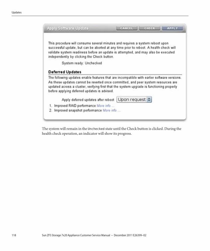
The system will remain in the Unchecked state until the Check button is clicked. During thehealth check operation, an indicator will show its progress.
Updates
Sun ZFS Storage 7x20 Appliance Customer Service Manual • December 2011 E26399–02118
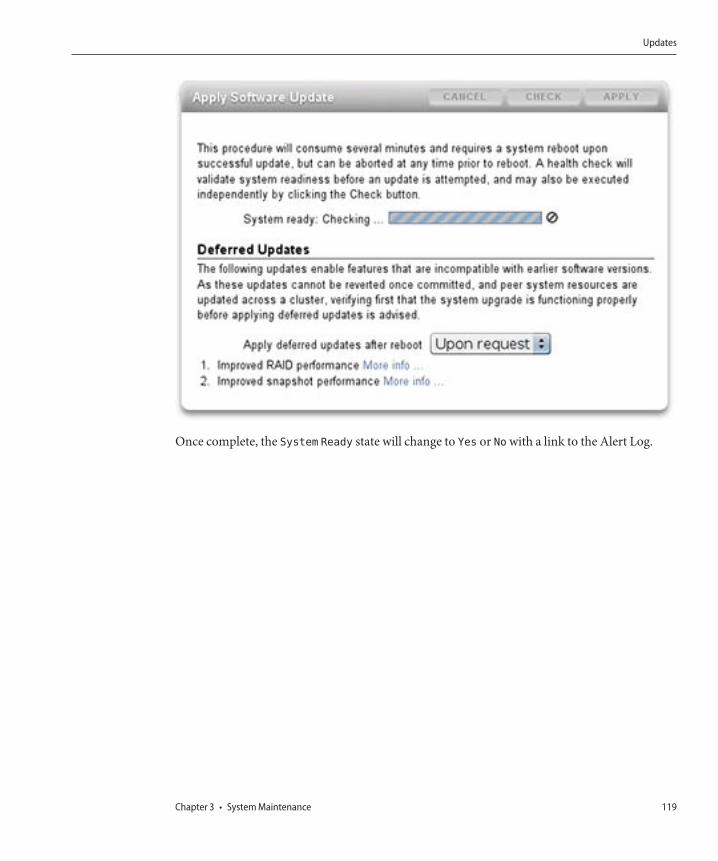
Once complete, the System Ready state will change to Yes or No with a link to the Alert Log.
Updates
Chapter 3 • System Maintenance 119
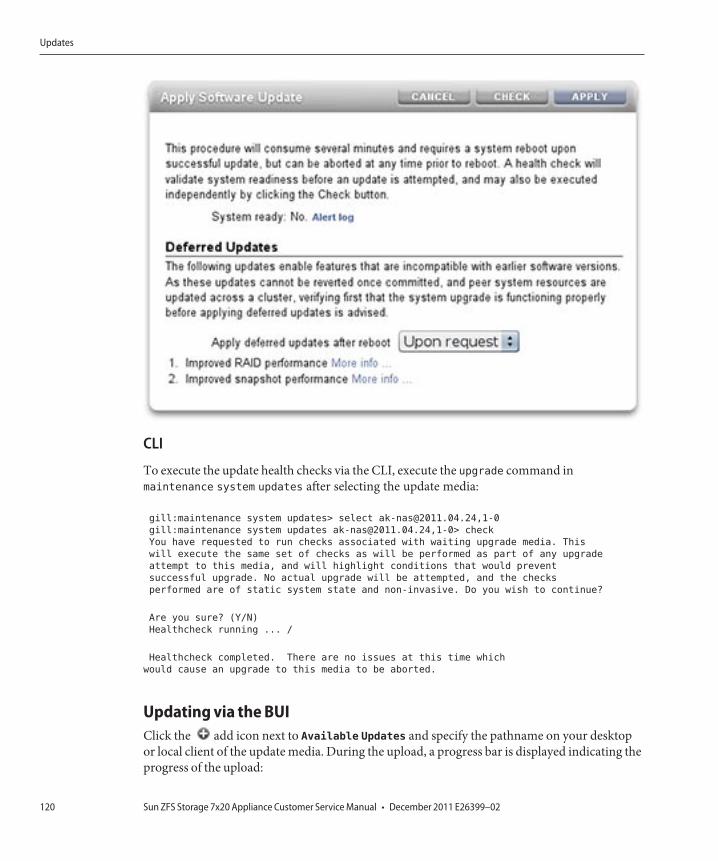
CLI
To execute the update health checks via the CLI, execute the upgrade command inmaintenance system updates after selecting the update media:
gill:maintenance system updates> select [email protected],1-0
gill:maintenance system updates [email protected],1-0> check
You have requested to run checks associated with waiting upgrade media. This
will execute the same set of checks as will be performed as part of any upgrade
attempt to this media, and will highlight conditions that would prevent
successful upgrade. No actual upgrade will be attempted, and the checks
performed are of static system state and non-invasive. Do you wish to continue?
Are you sure? (Y/N)
Healthcheck running ... /
Healthcheck completed. There are no issues at this time which
would cause an upgrade to this media to be aborted.
Updating via the BUIClick the add icon next to Available Updates and specify the pathname on your desktopor local client of the update media. During the upload, a progress bar is displayed indicating theprogress of the upload:
Updates
Sun ZFS Storage 7x20 Appliance Customer Service Manual • December 2011 E26399–02120
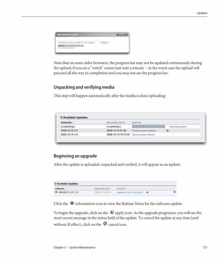
Note that on some older browsers, the progress bar may not be updated continuously duringthe upload; if you see a "watch" cursor just wait a minute -- in the worst case the upload willproceed all the way to completion and you may not see the progress bar.
Unpacking and verifying media
This step will happen automatically after the media is done uploading:
Beginning an upgrade
After the update is uploaded, unpacked and verified, it will appear as an update:
Click the information icon to view the Release Notes for the software update.
To begin the upgrade, click on the apply icon. As the upgrade progresses, you will see themost recent message in the status field of the update. To cancel the update at any time (andwithout ill effect), click on the cancel icon.
Updates
Chapter 3 • System Maintenance 121
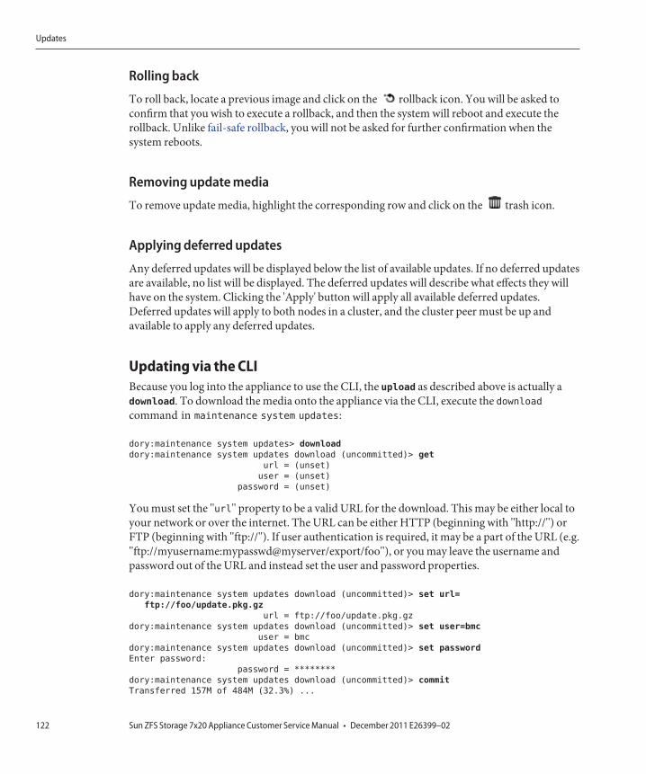
Rolling back
To roll back, locate a previous image and click on the rollback icon. You will be asked toconfirm that you wish to execute a rollback, and then the system will reboot and execute therollback. Unlike fail-safe rollback, you will not be asked for further confirmation when thesystem reboots.
Removing update media
To remove update media, highlight the corresponding row and click on the trash icon.
Applying deferred updates
Any deferred updates will be displayed below the list of available updates. If no deferred updatesare available, no list will be displayed. The deferred updates will describe what effects they willhave on the system. Clicking the 'Apply' button will apply all available deferred updates.Deferred updates will apply to both nodes in a cluster, and the cluster peer must be up andavailable to apply any deferred updates.
Updating via the CLIBecause you log into the appliance to use the CLI, the upload as described above is actually adownload. To download the media onto the appliance via the CLI, execute the downloadcommand in maintenance system updates:
dory:maintenance system updates> download
dory:maintenance system updates download (uncommitted)> get
url = (unset)
user = (unset)
password = (unset)
You must set the "url" property to be a valid URL for the download. This may be either local toyour network or over the internet. The URL can be either HTTP (beginning with "http://") orFTP (beginning with "ftp://"). If user authentication is required, it may be a part of the URL (e.g."ftp://myusername:mypasswd@myserver/export/foo"), or you may leave the username andpassword out of the URL and instead set the user and password properties.
dory:maintenance system updates download (uncommitted)> set url=
ftp://foo/update.pkg.gz
url = ftp://foo/update.pkg.gz
dory:maintenance system updates download (uncommitted)> set user=bmc
user = bmc
dory:maintenance system updates download (uncommitted)> set password
Enter password:
password = ********
dory:maintenance system updates download (uncommitted)> commit
Transferred 157M of 484M (32.3%) ...
Updates
Sun ZFS Storage 7x20 Appliance Customer Service Manual • December 2011 E26399–02122
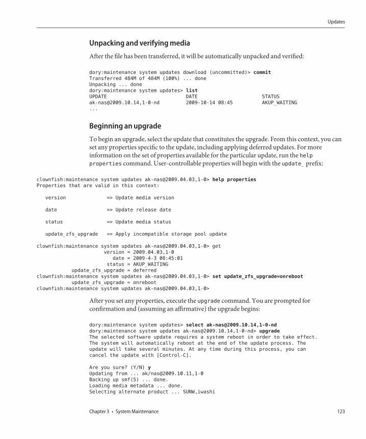
Unpacking and verifying media
After the file has been transferred, it will be automatically unpacked and verified:
dory:maintenance system updates download (uncommitted)> commit
Transferred 484M of 484M (100%) ... done
Unpacking ... done
dory:maintenance system updates> list
UPDATE DATE STATUS
[email protected],1-0-nd 2009-10-14 08:45 AKUP_WAITING
...
Beginning an upgrade
To begin an upgrade, select the update that constitutes the upgrade. From this context, you canset any properties specific to the update, including applying deferred updates. For moreinformation on the set of properties available for the particular update, run the helpproperties command. User-controllable properties will begin with the update_ prefix:
clownfish:maintenance system updates [email protected],1-0> help properties
Properties that are valid in this context:
version => Update media version
date => Update release date
status => Update media status
update_zfs_upgrade => Apply incompatible storage pool update
clownfish:maintenance system updates [email protected],1-0> get
version = 2009.04.03,1-0
date = 2009-4-3 08:45:01
status = AKUP_WAITING
update_zfs_upgrade = deferred
clownfish:maintenance system updates [email protected],1-0> set update_zfs_upgrade=onreboot
update_zfs_upgrade = onreboot
clownfish:maintenance system updates [email protected],1-0>
After you set any properties, execute the upgrade command. You are prompted forconfirmation and (assuming an affirmative) the upgrade begins:
dory:maintenance system updates> select [email protected],1-0-nd
dory:maintenance system updates [email protected],1-0-nd> upgrade
The selected software update requires a system reboot in order to take effect.
The system will automatically reboot at the end of the update process. The
update will take several minutes. At any time during this process, you can
cancel the update with [Control-C].
Are you sure? (Y/N) y
Updating from ... ak/[email protected],1-0
Backing up smf(5) ... done.
Loading media metadata ... done.
Selecting alternate product ... SUNW,iwashi
Updates
Chapter 3 • System Maintenance 123

Installing Sun Storage 7110 2009.10.14,1-0
pkg://sun.com/ak/SUNW,[email protected],1-0:20091014T084500Z
Creating system/boot/ak-nas-2009.10.14_1-0 ... done.
Creating system/root/ak-nas-2009.10.14_1-0 ... done.
...
As the upgrade proceeds, the latest message will be printed. You can cancel the upgrade at anytime by pressing ^C, at which point you will be prompted for confirmation:
Updating from ... ak/[email protected],1-0
Backing up smf(5) ... done.
Loading media metadata ... ^C
This will cancel the current update. Are you sure? (Y/N) y
error: interrupted by user
dory:maintenance system updates [email protected],1-0-nd>
Rolling back
To roll back to an earlier version, select the update that corresponds to that version and executethe rollback command. You will be asked to confirm that you wish to execute a rollback, andthen the system will reboot and execute the rollback. Unlike fail-safe rollback, you will not beasked for further confirmation when the system reboots.
Removing update media
To remove update media, use the destroy command, specifying the update to be removed:
dory:maintenance system updates> destroy [email protected],1-0-nd
This will destroy the update "[email protected],1-0-nd". Are you sure? (Y/N) y
dory:maintenance system updates>
Applying Deferred updates
To see if there are any available deferred updates, run the show command. If deferred updatesare available, you can use the apply command:
clownfish:maintenance system updates> show
Updates:
UPDATE DATE STATUS
[email protected],1-1.9 2009-4-1 04:18:48 AKUP_PREVIOUS
[email protected],1-0 2009-4-3 08:45:01 AKUP_CURRENT
Deferred updates:
The following incompatible updates are available. Applying these updates will
enable new software features as described below, but will prevent older
versions of the software from accessing the underlying resources. You should
apply deferred updates once you have verified that the current software update
is functioning and a rollback is not required. Applying deferred updates in a
cluster will also update any resources on the cluster peer.
Updates
Sun ZFS Storage 7x20 Appliance Customer Service Manual • December 2011 E26399–02124

1. Support for the "passthrough-x" aclinherit property for shares.
clownfish:maintenance system updates> apply
Applying deferred updates will prevent rolling back to previous versions of
software.
Are you sure? (Y/N)
clownfish:maintenance system updates> apply
Passthrough x
Passthrough-x Deferred UpdateFor filesystems, ACLs are inherited according to the "aclinherit" property on the filesystem (orinherited from the project). Previous versions of software allowed four options for this setting:"discard", "noallow", "restricted", and "passthrough". The 2009.Q2.0.0 release introduces a newoption, "passthrough-x", with slightly different semantics as described in the productdocumentation:
Same as 'passthrough', except that the owner, group, and everyone ACL entries inherit the executepermission only if the file creation mode also requests the execute bit.
The "passthrough" mode is typically used to cause all "data" files to be created with an identicalmode in a directory tree. An administrator sets up ACL inheritance so that all files are createdwith a mode, such as 0664 or 0666. This all works as expected for data files, but you might wantto optionally include the execute bit from the file creation mode into the inherited ACL. Oneexample is an output file that is generated from tools, such as "cc" or "gcc". If the inherited ACLdoesn't include the execute bit, then the output executable from the compiler won't beexecutable until you use chmod(1) to change the file's permissions.
In order to use this new mode, the storage pool must be upgraded. If you choose not to upgradethe pool and attempt to use this new property, you will get an error indicating that the storagepool needs to be upgraded first. There is no other implication of applying this update, and it canbe ignored if there is no need to use this new setting. Applying this update is equivalent toupgrading the on-disk ZFS pool to http://www.opensolaris.org/os/community/zfs/version/14/.(http://www.opensolaris.org/os/community/zfs/version/14/.)
User Quotas
User Quotas Deferred UpdateWith the 2009.Q3 software release, the system now supports user and group quotas on aper-share basis. In order to make use of this feature, a deferred update must be applied to
User Quotas
Chapter 3 • System Maintenance 125
upgrade all shares in the system to support this feature. Applying this deferred update alsoallows the current usage (user or group) to be queried on a per-filesystem or per-project basis.To quote the product documentation:
Quotas can be set on a user or group at the filesystem level. These enforce physical data usagebased on the POSIX or Windows identity of the owner or group of the file or directory. There aresome significant differences between user and group quotas and filesystem and project dataquotas.
Be sure to read the complete documentation under Space Management before attempting touse user or group quotas.
This update is applied in the background, and takes time proportional to the number of sharesand amount of data on the system. Until this deferred update is finished, attempt to apply userquotas will produce an error indicating that the update is still in progress.
COMSTAR
COMSTAR Deferred UpdateThe COMSTAR framework relies on a ZFS pool upgrade for complete support of persistentgroup reservations (PGRs). Before this upgrade has been applied, the number of reservationsstored with each LUN is severely limited, and may even be zero.
Applying this update is equivalent to upgrading the on-disk ZFS pool to version 16.
Triple Parity RAID
Triple-Parity RAID Deferred UpdateThis update provides the ability to use the triple-parity RAID storage profile, RAID-Z withthree parity sectors per stripe. Triple-parity offers increased protection against drive failuresand additional overall availability.
In order to use this new mode, the storage pool must be upgraded. If you choose not to upgradethe pool and attempt to use this new property, you will get an error indicating that the storagepool needs to be upgraded first. There is no other implication of applying this update, and it canbe ignored if there is no need to use this new setting. Applying this update is equivalent toupgrading the on-disk ZFS pool to version 17.
COMSTAR
Sun ZFS Storage 7x20 Appliance Customer Service Manual • December 2011 E26399–02126
Dedup
Data Deduplication Deferred UpdateThis update provides the ability to use data deduplication.
In order to use this new mode, the storage pool must be upgraded. If you choose not to upgradethe pool and attempt to use this new property, you will get an error indicating that the storagepool needs to be upgraded first. There is no other implication of applying this update, and it canbe ignored if there is no need to use this new setting. Applying this update is equivalent toupgrading the on-disk ZFS pool to version 21.
Replication
Replication Deferred UpdateThe 2010.Q1 release stores replication configuration differently than 2009.Q3 and earlierreleases. This update migrates existing target, action, and replica configuration created underan earlier release to the new form used by 2010.Q1 and later.
After upgrading to 2010.Q1 but before this update is applied, incoming replication updates forexisting replicas will fail. Replicas received under earlier releases will not be manageable via theBUI or CLI, though they will occupy space in the storage pool. Additionally, the system will notsend replication updates for actions configured on earlier releases.
After applying this update, incoming replication updates for replicas originally received onearlier releases will continue normally and without a full resync. The system will also sendincremental replication updates for actions configured under earlier releases.
Received Properties
Received Properties Deferred UpdateThe 2010.Q1 feature that enables administrators to customize properties on replicated sharesrelies on a ZFS pool upgrade. This upgrade provides support of persistent local changes toreceived properties. Before this upgrade has been applied, the system will not allowadministrators to change properties on replicated shares.
Applying this update is equivalent to upgrading the on-disk ZFS pool to version 22.
Received Properties
Chapter 3 • System Maintenance 127
Slim ZIL
IntroductionThis deferred update changes the layout of ZFS intent log blocks to improve synchronous writeperformance. These improvements rely on a ZFS pool upgrade provided by this update. Beforethis update has been applied, log records will continue to be written in the old format andperformance may be reduced.
Applying this update is equivalent to upgrading the on-disk ZFS pool to version 23.
Snapshot Deletion
Snapshot Deletion Deferred UpdateThis deferred update increases snapshot deletion parallelism and reduces the size of transactiongroups associated with snapshot deletion to improve systemic responsiveness. Theseimprovements rely on a ZFS pool upgrade provided by this update. Before this update has beenapplied, new snapshot data will be stored in the old format and deleted using the old algorithm.Note that any snapshots created before this update is applied will also be deleted using the oldalgorithm.
Applying this update is equivalent to upgrading the on-disk ZFS pool version 26.
Recursive Snapshots
Recursive Snapshots Deferred UpdateThis deferred update allows recursive snapshots to be taken without suspending the ZFS intentlog, which greatly improves snapshot creation performance especially on heavily loadedcontrollers. These improvements rely on a ZFS pool upgrade provided by this update. Beforethis update has been applied, the system will be able to create snapshots but will do so using theold, much slower, algorithm.
Applying this update is equivalent to upgrading the on-disk ZFS pool to version 27.
Slim ZIL
Sun ZFS Storage 7x20 Appliance Customer Service Manual • December 2011 E26399–02128
Multi Replace
Multi Replace Deferred UpdateThis deferred update allows importing a pool with a missing log device and corrects thebehavior of the system when a device that is being resilvered is itself removed or replaced. Thesefixes rely on a ZFS pool upgrade provided by this update. Before this update has been applied,the system will be unable to import pools with missing log devices and will not correctly handlereplacement of resilvering devices (see CR 6782540).
Applying this update is equivalent to upgrading the on-disk ZFS pool to version 28.
RAIDZ Mirror
RAIDZ/Mirror Deferred UpdateThis deferred update improves both latency and throughput on several important workloads.These improvements rely on a ZFS pool upgrade provided by this update. Applying this updateis equivalent to upgrading the on-disk ZFS pool to version 29.
Optional Child Dir
IntroductionThis deferred update improves list retrieval performance and replication deletion performanceby improving dataset rename speed. These improvements rely on a ZFS pool upgrade providedby this update. Before this update has been applied, the system will be able to retrieve lists anddelete replications, but will do so using the old, much slower, recursive rename code. Applyingthis update is equivalent to upgrading the on-disk ZFS pool to version 31.
Optional Child Dir
Chapter 3 • System Maintenance 129
ConfigurationBackup
Configuration BackupThe configuration backup function enables the administrator to:
■ Backup the appliance configuration, consisting of system metadata only (such as thenetwork configuration, local users and roles, service settings, and other appliancemetadata).
■ Restore a previously saved configuration from a backup.
■ Export a saved configuration, as a plain file, so that it may be stored on an external server, orincluded in a backup of a share on the appliance itself.
■ Import a saved configuration that was previously exported from this system or anothersystem, making it available for a restore operation.
Backup ContentsA configuration backup does include:
■ Metadata associated with the system as a whole, such as settings for NTP, NIS, LDAP, andother services.
■ Network device, datalink, and interface configuration.■ User accounts, roles and privileges, preferences, and encrypted passwords for local users
(not directory users).■ Alerts and thresholds and their associated rules.
A configuration backup does not include:
■ User data (shares and LUNs). Your user data must be backed up separately, using NDMPbackup software, snapshots, and/or remote replication.
■ User passwords for directory users. These remain stored solely in your separate networkdirectory service, such as LDAP or Active Directory, and will not be stored in the backup orrestored.
■ Metadata directly associated with user data, such as snapshot schedules, user quotas,compression settings, and other attributes of shares and LUNs.
■ Analytics and logs. Events can be redirected to external SNMP trap receivers or e-maildestinations using Alerts rules.
■ System software. The system software is automatically backed up as part of the SystemUpdate capability.
ConfigurationBackup
Sun ZFS Storage 7x20 Appliance Customer Service Manual • December 2011 E26399–02130
Restore ImpactThe restore operation takes a selected configuration backup, and modifies all of thecorresponding system settings to reflect those in the backup, including removing aspects of theconfiguration that were not present at the time of the backup. Administrators should adhere tothe following guidelines when planning a restore:■ Scheduled downtime - The restore process takes several minutes to complete and will
impact service to clients, as the active networking configuration and data protocols arereconfigured. Therefore, a configuration restore should only be used on a developmentsystem, or during a scheduled downtime.
■ Service interruption - Clients accessing data on the system through a data protocol suchas NFS will see service interrupted, as the network is reconfigured and the NFS servicerestarted. If the selected backup copy was taken when a service was disabled by theadministrator, that setting will be restored, and therefore client sessions will be terminatedfor that protocol.
■ Session interruption - If restore is initiated from a web browser, that web browsersession will also be disconnected during the restore process as the network is reconfigured.If the restored configuration does not include the same routing and network addresssettings used by the current browser connection, or if the browser is connected to a networkaddress managed by DHCP, the browser session will be interrupted during the restore. Therestore process will complete in the background, but you will need to reload or point thebrowser at a new, restored network address to continue. For this reason, it may be desirableto initiate a complex configuration restore from the service processor serial console usingthe CLI.
■ Un-cluster, restore, and re-cluster - Configuration backups may be initiated forappliances that are joined in a cluster, but a configuration restore may not be used whilesystems are actively clustered. The clustering process means that settings are beingsynchronized between cluster peers, and each peer appliance also is maintaining privatesettings. For this reason, you must first use the Unconfiguring Clustering procedure toun-cluster the two systems. Then, restore the configuration backup on a selected head, andthen re-cluster the two systems, at which point the other system will automaticallysynchronize itself with the restored configuration.
■ Root privileges required - Configuration backups include all system metadata, andtherefore require all possible privileges and authorizations to create or apply. Therefore,unlike other delegated administrative options, only the root user is authorized to perform aconfiguration backup or restore.
■ Verify setting for new features - It is permitted to restore a configuration that wassaved before applying a system update to a new version of the appliance software. In somecases, services and properties that were present at the time of the backup may have differenteffects, and new services and properties may exist in the newer software that did not exist atthe time of the backup. Similar to the system update process, the configuration restoreprocess will make every effort to transfer applicable settings, and apply reasonable defaults
ConfigurationBackup
Chapter 3 • System Maintenance 131
to those properties that did not exist at the time of the backup. When restoring acrosssoftware versions, administrators should manually verify settings for new features followingthe restore.
■ Password maintenance - The root password is not changed or reverted to the password atthe time of the backup if it was different. The current root password is maintained on thesystem across the restore. For more details about passwords, refer to the summary ofSecurity Considerations.
Security ConsiderationsA configuration backup contains information that is normally only accessible to the rootadministrative user on the appliance. Therefore, any configuration backup that is exported toanother system or into a filesystem share must apply security restrictions to the backup file toensure that unauthorized users cannot read the backup file.
Local user passwords are stored in the backup file in encrypted (hashed) format, not as cleartext. However, on the system, access to these password hashes is restricted, as they could be usedas input to dictionary attacks. Therefore, administrators must carefully protect configurationbackups that are exported, either by restricting file access to the backup, or by applying anadditional layer of encryption to the entire backup file, or both.
Directory user passwords are not stored in the appliance, and therefore are not stored in theconfiguration backup. If you have deployed a directory service such as LDAP or AD foradministrative user access, there are no copies of directory service password hashes fordirectory users stored in the configuration backup. Only the user name, user ID, preferences,and authorization settings for directory users are stored in the backup and then restored.
Following a configuration restore, the local root administrative user password is not modifiedto the root password at the time of the backup. The root password is left as-is, unmodified, bythe restore process, to ensure that the password used by the administrator who is executing therestore process (and thus has logged in, using that password) is retained. If the administrator'sintent was to also change the root password at the time of configuration restore, that step mustbe executed manually following the restore, using the normal administrative password changeprocedure.
Managing Configuration Backups Using the BUIThe following section outlines how various Configuration Backup tasks can be accomplishedusing the Configuration Backup area near the bottom of the Maintenance > System screen inthe BUI.
Create a Configuration Backup
To create a backup, simply click the "Backup" button above the list of saved configurations andfollow the instructions. You will be prompted to enter a descriptive comment for the backup.
ConfigurationBackup
Sun ZFS Storage 7x20 Appliance Customer Service Manual • December 2011 E26399–02132
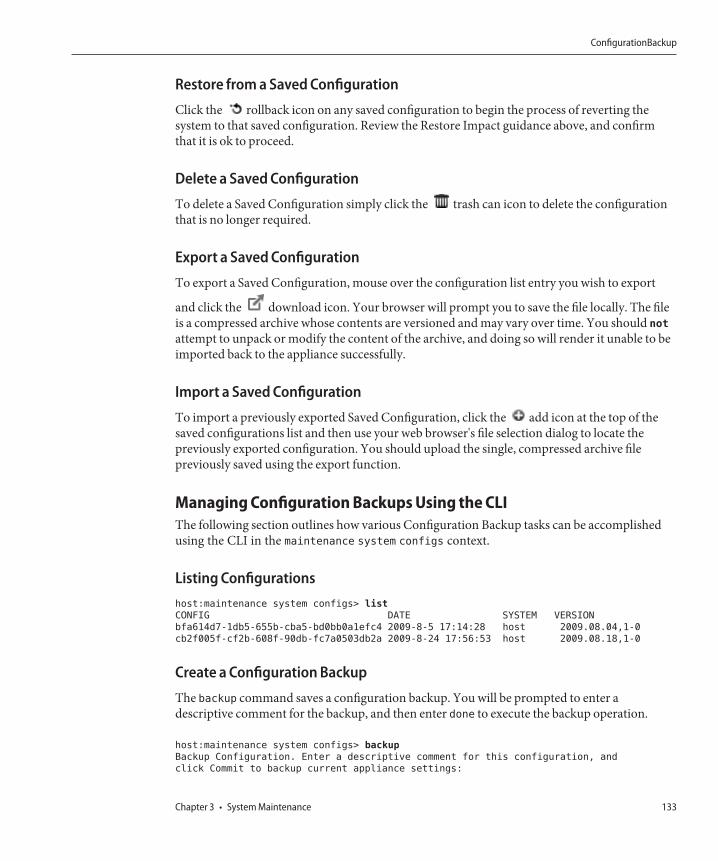
Restore from a Saved Configuration
Click the rollback icon on any saved configuration to begin the process of reverting thesystem to that saved configuration. Review the Restore Impact guidance above, and confirmthat it is ok to proceed.
Delete a Saved Configuration
To delete a Saved Configuration simply click the trash can icon to delete the configurationthat is no longer required.
Export a Saved Configuration
To export a Saved Configuration, mouse over the configuration list entry you wish to export
and click the download icon. Your browser will prompt you to save the file locally. The fileis a compressed archive whose contents are versioned and may vary over time. You should not
attempt to unpack or modify the content of the archive, and doing so will render it unable to beimported back to the appliance successfully.
Import a Saved Configuration
To import a previously exported Saved Configuration, click the add icon at the top of thesaved configurations list and then use your web browser's file selection dialog to locate thepreviously exported configuration. You should upload the single, compressed archive filepreviously saved using the export function.
Managing Configuration Backups Using the CLIThe following section outlines how various Configuration Backup tasks can be accomplishedusing the CLI in the maintenance system configs context.
Listing Configurationshost:maintenance system configs> list
CONFIG DATE SYSTEM VERSION
bfa614d7-1db5-655b-cba5-bd0bb0a1efc4 2009-8-5 17:14:28 host 2009.08.04,1-0
cb2f005f-cf2b-608f-90db-fc7a0503db2a 2009-8-24 17:56:53 host 2009.08.18,1-0
Create a Configuration Backup
The backup command saves a configuration backup. You will be prompted to enter adescriptive comment for the backup, and then enter done to execute the backup operation.
host:maintenance system configs> backup
Backup Configuration. Enter a descriptive comment for this configuration, and
click Commit to backup current appliance settings:
ConfigurationBackup
Chapter 3 • System Maintenance 133
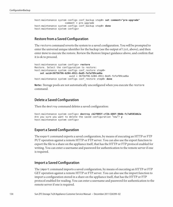
host:maintenance system configs conf_backup step0> set comment="pre-upgrade"
comment = pre-upgrade
host:maintenance system configs conf_backup step0> done
host:maintenance system configs>
Restore from a Saved Configuration
The restore command reverts the system to a saved configuration. You will be prompted toenter the universal unique identifier for the backup (see the output of list, above), and thenenter done to execute the restore. Review the Restore Impact guidance above, and confirm thatit is ok to proceed.
host:maintenance system configs> restore
Restore. Select the configuration to restore:
host:maintenance system configs conf_restore step0>
set uuid=36756f96-b204-4911-8ed5-fefaf89cad6a
uuid = 36756f96-b204-4911-8ed5-fefaf89cad6a
host:maintenance system configs conf_restore step0> done
Note: Storage pools are not automatically unconfigured when you execute the restorecommand.
Delete a Saved Configuration
Then the destroy command deletes a saved configuration:
host:maintenance system configs> destroy cb2f005f-cf2b-608f-90db-fc7a0503db2a
Are you sure you want to delete the saved configuration "new"? y
host:maintenance system configs>
Export a Saved Configuration
The export command exports a saved configuration, by means of executing an HTTP or FTPPUT operation against a remote HTTP or FTP server. You can also use the export function toexport the file to a share on the appliance itself, that has the HTTP or FTP protocol enabled forwriting. You can enter a username and password for authentication to the remote server if oneis required.
Import a Saved Configuration
The import command imports a saved configuration, by means of executing an HTTP or FTPGET operation against a remote HTTP or FTP server. You can also use the import function toimport a configuration stored in a share on the appliance itself, that has the HTTP or FTPprotocol enabled for reading. You can enter a username and password for authentication to theremote server if one is required.
ConfigurationBackup
Sun ZFS Storage 7x20 Appliance Customer Service Manual • December 2011 E26399–02134
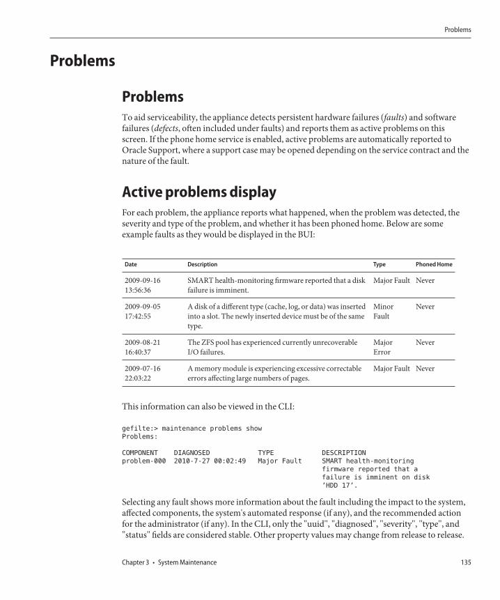
Problems
ProblemsTo aid serviceability, the appliance detects persistent hardware failures (faults) and softwarefailures (defects, often included under faults) and reports them as active problems on thisscreen. If the phone home service is enabled, active problems are automatically reported toOracle Support, where a support case may be opened depending on the service contract and thenature of the fault.
Active problems displayFor each problem, the appliance reports what happened, when the problem was detected, theseverity and type of the problem, and whether it has been phoned home. Below are someexample faults as they would be displayed in the BUI:
Date Description Type Phoned Home
2009-09-1613:56:36
SMART health-monitoring firmware reported that a diskfailure is imminent.
Major Fault Never
2009-09-0517:42:55
A disk of a different type (cache, log, or data) was insertedinto a slot. The newly inserted device must be of the sametype.
MinorFault
Never
2009-08-2116:40:37
The ZFS pool has experienced currently unrecoverableI/O failures.
MajorError
Never
2009-07-1622:03:22
A memory module is experiencing excessive correctableerrors affecting large numbers of pages.
Major Fault Never
This information can also be viewed in the CLI:
gefilte:> maintenance problems show
Problems:
COMPONENT DIAGNOSED TYPE DESCRIPTION
problem-000 2010-7-27 00:02:49 Major Fault SMART health-monitoring
firmware reported that a
failure is imminent on disk
’HDD 17’.
Selecting any fault shows more information about the fault including the impact to the system,affected components, the system's automated response (if any), and the recommended actionfor the administrator (if any). In the CLI, only the "uuid", "diagnosed", "severity", "type", and"status" fields are considered stable. Other property values may change from release to release.
Problems
Chapter 3 • System Maintenance 135
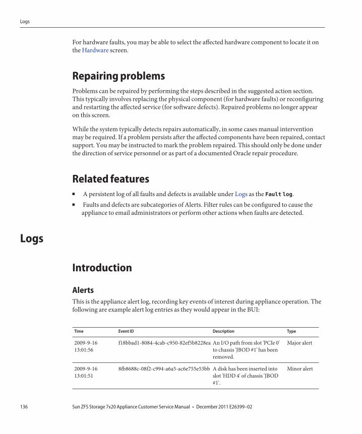
For hardware faults, you may be able to select the affected hardware component to locate it onthe Hardware screen.
Repairing problemsProblems can be repaired by performing the steps described in the suggested action section.This typically involves replacing the physical component (for hardware faults) or reconfiguringand restarting the affected service (for software defects). Repaired problems no longer appearon this screen.
While the system typically detects repairs automatically, in some cases manual interventionmay be required. If a problem persists after the affected components have been repaired, contactsupport. You may be instructed to mark the problem repaired. This should only be done underthe direction of service personnel or as part of a documented Oracle repair procedure.
Related features■ A persistent log of all faults and defects is available under Logs as the Fault log.■ Faults and defects are subcategories of Alerts. Filter rules can be configured to cause the
appliance to email administrators or perform other actions when faults are detected.
Logs
Introduction
AlertsThis is the appliance alert log, recording key events of interest during appliance operation. Thefollowing are example alert log entries as they would appear in the BUI:
Time Event ID Description Type
2009-9-1613:01:56
f18bbad1-8084-4cab-c950-82ef5b8228ea An I/O path from slot 'PCIe 0'to chassis 'JBOD #1' has beenremoved.
Major alert
2009-9-1613:01:51
8fb8688c-08f2-c994-a6a5-ac6e755e53bb A disk has been inserted intoslot 'HDD 4' of chassis 'JBOD#1'.
Minor alert
Logs
Sun ZFS Storage 7x20 Appliance Customer Service Manual • December 2011 E26399–02136
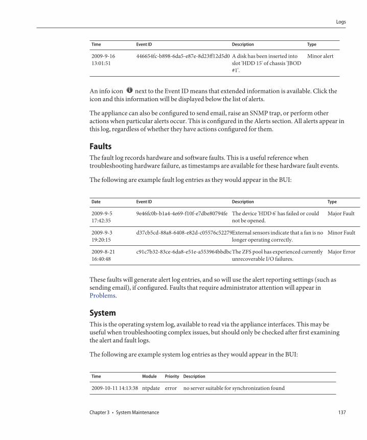
Time Event ID Description Type
2009-9-1613:01:51
446654fc-b898-6da5-e87e-8d23ff12d5d0 A disk has been inserted intoslot 'HDD 15' of chassis 'JBOD#1'.
Minor alert
An info icon next to the Event ID means that extended information is available. Click theicon and this information will be displayed below the list of alerts.
The appliance can also be configured to send email, raise an SNMP trap, or perform otheractions when particular alerts occur. This is configured in the Alerts section. All alerts appear inthis log, regardless of whether they have actions configured for them.
FaultsThe fault log records hardware and software faults. This is a useful reference whentroubleshooting hardware failure, as timestamps are available for these hardware fault events.
The following are example fault log entries as they would appear in the BUI:
Date Event ID Description Type
2009-9-517:42:35
9e46fc0b-b1a4-4e69-f10f-e7dbe80794fe The device 'HDD 6' has failed or couldnot be opened.
Major Fault
2009-9-319:20:15
d37cb5cd-88a8-6408-e82d-c05576c52279External sensors indicate that a fan is nolonger operating correctly.
Minor Fault
2009-8-2116:40:48
c91c7b32-83ce-6da8-e51e-a553964bbdbcThe ZFS pool has experienced currentlyunrecoverable I/O failures.
Major Error
These faults will generate alert log entries, and so will use the alert reporting settings (such assending email), if configured. Faults that require administrator attention will appear inProblems.
SystemThis is the operating system log, available to read via the appliance interfaces. This may beuseful when troubleshooting complex issues, but should only be checked after first examiningthe alert and fault logs.
The following are example system log entries as they would appear in the BUI:
Time Module Priority Description
2009-10-11 14:13:38 ntpdate error no server suitable for synchronization found
Logs
Chapter 3 • System Maintenance 137

Time Module Priority Description
2009-10-11 14:03:52 genunix notice ^MSunOS Release 5.11 Version ak/[email protected],1-0 64-bit
2009-10-11 14:02:04 genunix notice done
2009-10-11 14:02:01 genunix notice syncing file systems...
2009-10-11 13:52:16 nxge warningWARNING: nxge : ==> nxge_rxdma_databuf_free: DDI
AuditThe audit log records user activity events, including login and logout to the BUI and CLI, andadministrative actions. If session annotations are used (see Users), each audit entry should benoted with a reason.
The following are example audit log entries as they would appear in the BUI:
Time User Host Summary Session Annotation
2009-10-12 05:20:24 root deimos Disabled ftp service
2009-10-12 03:17:05 root deimos User logged in
2009-10-11 22:38:56 root deimos Browser session timed out
2009-10-11 21:13:35 root <console> Enabled ftp service
Phone HomeIf Phone Home is used, this log will show communication events with Oracle support.
The following are example phone home entry as it would appear in the BUI:
Time Description Result
2009-10-1205:24:09
Uploaded file 'cores/ak.45e5ddd1-ce92-c16e-b5eb-9cb2a8091f1c.tar.gz' to Oraclesupport
OK
BUIUse the Maintenance > Logs screen to navigate logs using list controls, and switch between logsusing the local navigation buttons.
CLILogs can be viewed under the maintenance logs section of the CLI.
Logs
Sun ZFS Storage 7x20 Appliance Customer Service Manual • December 2011 E26399–02138
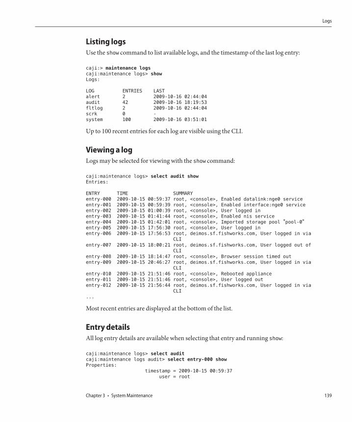
Listing logsUse the show command to list available logs, and the timestamp of the last log entry:
caji:> maintenance logs
caji:maintenance logs> show
Logs:
LOG ENTRIES LAST
alert 2 2009-10-16 02:44:04
audit 42 2009-10-16 18:19:53
fltlog 2 2009-10-16 02:44:04
scrk 0 -
system 100 2009-10-16 03:51:01
Up to 100 recent entries for each log are visible using the CLI.
Viewing a logLogs may be selected for viewing with the show command:
caji:maintenance logs> select audit show
Entries:
ENTRY TIME SUMMARY
entry-000 2009-10-15 00:59:37 root, <console>, Enabled datalink:nge0 service
entry-001 2009-10-15 00:59:39 root, <console>, Enabled interface:nge0 service
entry-002 2009-10-15 01:00:39 root, <console>, User logged in
entry-003 2009-10-15 01:41:44 root, <console>, Enabled nis service
entry-004 2009-10-15 01:42:01 root, <console>, Imported storage pool "pool-0"entry-005 2009-10-15 17:56:30 root, <console>, User logged in
entry-006 2009-10-15 17:56:53 root, deimos.sf.fishworks.com, User logged in via
CLI
entry-007 2009-10-15 18:00:21 root, deimos.sf.fishworks.com, User logged out of
CLI
entry-008 2009-10-15 18:14:47 root, <console>, Browser session timed out
entry-009 2009-10-15 20:46:27 root, deimos.sf.fishworks.com, User logged in via
CLI
entry-010 2009-10-15 21:51:46 root, <console>, Rebooted appliance
entry-011 2009-10-15 21:51:46 root, <console>, User logged out
entry-012 2009-10-15 21:56:44 root, deimos.sf.fishworks.com, User logged in via
CLI
...
Most recent entries are displayed at the bottom of the list.
Entry detailsAll log entry details are available when selecting that entry and running show:
caji:maintenance logs> select audit
caji:maintenance logs audit> select entry-000 show
Properties:
timestamp = 2009-10-15 00:59:37
user = root
Logs
Chapter 3 • System Maintenance 139
address = <console>
summary = Enabled datalink:nge0 service
annotation =
The "annotation" is the session annotation, which can be enabled when configuring users.
Logs
Sun ZFS Storage 7x20 Appliance Customer Service Manual • December 2011 E26399–02140
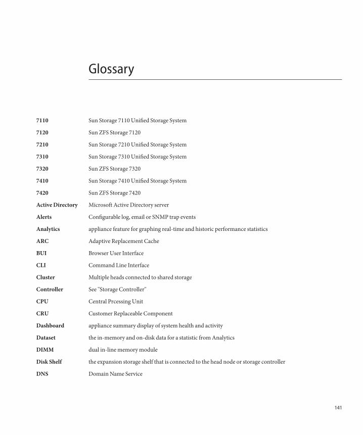
Glossary
7110 Sun Storage 7110 Unified Storage System
7120 Sun ZFS Storage 7120
7210 Sun Storage 7210 Unified Storage System
7310 Sun Storage 7310 Unified Storage System
7320 Sun ZFS Storage 7320
7410 Sun Storage 7410 Unified Storage System
7420 Sun ZFS Storage 7420
Active Directory Microsoft Active Directory server
Alerts Configurable log, email or SNMP trap events
Analytics appliance feature for graphing real-time and historic performance statistics
ARC Adaptive Replacement Cache
BUI Browser User Interface
CLI Command Line Interface
Cluster Multiple heads connected to shared storage
Controller See ''Storage Controller''
CPU Central Prcessing Unit
CRU Customer Replaceable Component
Dashboard appliance summary display of system health and activity
Dataset the in-memory and on-disk data for a statistic from Analytics
DIMM dual in-line memory module
Disk Shelf the expansion storage shelf that is connected to the head node or storage controller
DNS Domain Name Service
141

DTrace a comprehensive dynamic tracing framework for troubleshooting kernel and application problems onproduction systems in real-time
FC Fibre Channel
FRU Field Replaceable Component
FTP File Transfer Protocol
GigE Gigabit Ethernet
HBA Host Bus Adapter
HCA Host Channel Adapter
HDD Hard Disk Drive
HTTP HyperText Transfer Protocol
Hybrid StoragePool
combines disk, flash, and DRAM into a single coherent and seamless data store.
Icons icons visible in the BUI
iSCSI Internet Small Computer System Interface
Kiosk a restricted BUI mode where a user may only view one specific screen
L2ARC Level 2 Adaptive Replacement Cache
LDAP Lightweight Directory Access Protocol
LED light-emitting diode
Logzilla write IOPS accelerator
LUN Logical Unit
Masthead top section of BUI screen
Modal Dialog a new screen element for a specific function
NFS Network File System
NIC Network Interface Card
NIS Network Information Service
PCIe Peripheral Component Interconnect Express
Pool provide storage space that is shared across all filesystems and LUNs
Project a collection of shares
PSU Power Supply Unit
DTrace
Sun ZFS Storage 7x20 Appliance Customer Service Manual • December 2011 E26399–02142
QDR quad data rate
Readzilla read-optimized flash SSD for the L2ARC
RemoteReplication
replicating shares to another appliance
Rollback reverts all of the system software and all of the metadata settings of the system back to their state just priorto applying an update
SAS Serial Attached SCSI
SAS-2 Serial Attached SCSI 2.0
SATA Serial ATA
Schema configurable properties for shares
Scripting automating CLI tasks
Service appliance service software
Share ZFS filesystem shared using data protocols
SIM SAS Interface Module
Snapshot an image of a share
SSD Solid State Drive
SSH Secure Shell
Statistic a metric visible from Analytics
Storage Controller the head node of the appliance
Support Bundle auto-generated files containing system configuration information and core files for use by remote supportin debugging system failures
Title Bar local navigation and function section of BUI screen
Updates software or firmware updates
WebDAV Web based Distributed Authoring and Versioning
ZFS on-disk data storage subsystem
ZFS
143

144
Index
Numbers and Symbols7120, 24, 25, 27, 29, 31, 32, 33, 34, 53, 677320, 34, 35, 36, 37, 38, 39, 40, 41, 42, 43, 53
DDIMM, 47, 48, 49Disk Shelf, 80, 81, 83, 84
FFRU, 35
HHardware, Locating a failed component, 21
LLogzilla, 25, 32
SShelf
Replacing a Drive, 87–89Replacing a Power Supply, 89–91Replacing a SIM Board, 91–93
SIM, 81, 84, 91
SSD, 75
UUpdates, 111, 112
145

146