summer training project report on construction of wbhidco state convention centre
TRANSCRIPT

A PROJECT REPORT ON CONSTRUCTION OF
WBHIDCO BISWA BANGLA
CONVENTION CENTRE
By
The largest convention centre in India with a capacity of 3000 people

One month Summer Internship Programme
Site Address:Plot no. DG/02/01 in AA-1B, NewTown, Kolkata

This is to declare that KAUSHIK KANJI pursuing his B.Tech, 4TH
Year from Techno India, Salt
Lake has successfully completed Summer Internship at WBHIDCO BISWA BANGLA
CONVENTION CENTRE, New town, Kolkata from 01.07.2016 to 30.07.2016.
We found him sincere, hardworking, technically sound and result oriented. He worked well
as part of a team during his tenure. We take this opportunity to thank him and wish him all
the best for her future.
Date:
Place: KOLKATA
Signature
S. K. BASU
PROJECT HEAD
LARSEN & TOUBRO LTD.- CONSTRUCTION
WBHIDCO BISWA BANGLA CONVENTION CENTRE

ACKNOWLEDGEMENT
A winter internship project is a golden opportunity for learning and self-development. I
consider myself very lucky and honoured to have so many wonderful people lead me
through in completion of this project.
I wish to express my indebted gratitude and special thanks to Mr. S.K. Basu, Project Head
(WBHIDCO BISWA BANGLA CONVENTION CENTRE CONSTRUCTION PROJECT) who in spite
of being extraordinarily busy with his duties, took time out to hear, guide and keep me on
the correct path and allowing me to carry out my industrial project work at their esteemed
organization and extending during the training. I do not know where I would have been
without him.
A hu ble Tha k you Sir.
I express my deepest thanks to Mr. Rajiv Chowdhury (Planning in charge), Mr. Ramesh
Mukherjee (Formwork in Charge), Mr. Niranjan Kumar (QA/QC in charge), Mr L.C Santra
(Construction Manager), Mr. S. Bhattacharya (Finishing works in charge) for taking part in
useful decision & giving necessary advices and guidance and arranged all facilities to make
the learning process a lot easier. I choose this moment to acknowledge their contribution
gratefully. Also, I express my gratitude to Mr. Koushik Das (Administrative Head) for co-
operating with me throughout the project and helping me always in need.
It is my glowing feeling to place on record my best regards, deepest sense of gratitude to
Mr. Mrinmoy Bhowmick (Senior Engineer), Mr. Amar Gupta (QA/QC engineer) Mr.
Dhananjay Kumar (Finishing Engineer) for their judicious and precious guidance which were
extremely valuable for my study both theoretically and moreover practically.
I express my deepest thanks to Prof. Kalyan Roy (Training and Placement Officer) for his
guidance and support. They supported me by showing different method of information
collection about the company. He helped all time when I needed and gave right direction
toward completion of project.
Place: KOLKATA
Date: Signature:
Kaushik Kanji
Contact no: 8013754622 or 9477745105
e-mail: [email protected]

TABLE OF CONTENTS
SL
NO
DESCRIPTION PAGE NO.
1 ABSTRACT 1
2 SITE OVERVIEW 2-6
3 FORMWORK SYSTEMS 6-17
4 ACCESS SCAFFOLDINGS 18-19
5 STAIR TOWER 20-21
6 USE OF FORMWORK COMPONENTS 22
7 TOOLS AND TACKLES REQUIRED 23
8 QUALITY ASSURANCE 24-27
9 QUALITY CONTROL 28-40
10 REINFORCED CONCRETE WORKS 41-46
11 FINISHING WORKS 47-50
12 PLANTS & MACHINERY 51
13 PICTURES 52-82
14 CONCLUSION 83
15 BIBILOGRAPHY 84

1 | P a g e
ABSTRACT
Civil Engineering is the most prestigious and challenging field now days. Hence we need to
examine everything and work accordingly, maintaining enough safety and ensuring good
quality work. On any construction it is important to work according to the drawings
provided by Planning and Design section. But sometimes the actual site conditions may
differ and site engineers should either take instant decisions or to inform the design section
to revise the drawing to work accordingly.
In any site Human resource management is the primary crucial part we need to take
care of. We should ensure safety and use the human resource in most efficient way. As the
WBHIDCO BISWA BANGLA CONVENTION CENTRE Constructed by L&T Buildings and
Factories Integrated Company Pvt. Ltd is an item rate contract, the management of human
resource is of great significance. In L&T, every workers are given 8 on site trainings per
month by Site engineers. It is an integrated part of EHS (Employee Health and Safety)
programme.
Another very important thing which should be maintained in any company is strict quality
control in execution work. Working with unskilled and semi skilled workers are very difficult
as they are unaware of the consequences for their wrong doings. Hence strict quality
control should be maintained to get the work done safely and with efficiency by the
workers.
During the time of internship programme I was able to see how a work with extreme safety
and strict quality control is done on site and how it is monitored methodologically by ITP,
Checklists etc. I feel fortunate enough to learn about the exclusive formwork systems of L&T
which is designed by ECC division at Puducherry. I learnt about how the tests are done at
quality control lab to maintain extremely good quality. I have learnt how concreting is done
on batching plants. Learnt about many new machinery.
I learnt about different safety measures, how to manage human resources, how execution
work is done on field and many other small things that I shall need throughout my journey
in the field of Civil Engineering.
A summary of the things learnt at site: 1. L&T Formwork systems
2. Concreting works- Pilecaps, R.C.C walls, columns, beams, slabs, lintels
3. Brickwork
4. Internal and external plastering
5. IPS flooring
6. Sandstone cladding on outside
7. Roof sheathing
8. Quality assurance and Quality control
9. Plants and machinery

2 | P a g e
AN OVERVIEW OF
WBHIDCO BISWA BANGLA CONVENTION CENTRE
SITE MAP OF WBHIDCO BISWA BANGLA CONVENTION CENTRE

3 | P a g e
SITE ADDRESS : Plot no. DG/02/01 in AA-1B, New
Town, Kolkata
TOTAL PLOT AREA : 10 ACRE
BUILT UP AREA OF CONVENTION BLOCK : 2,81,546sq.ft
BUILT UP AREA OF RESIDENCY (BUSINESS HOTEL) :1,75,737sq.ft
BUILT UP AREA OF MLCP : 2,35,503sq.ft.
PROJECT WORTH : 385 CRORE
START DATE : 16.06.2014
EXPECTED FINISH DATE : 30.03.2017
TOTAL CONCRETE ESTIMATED : 55000Cu.m
TOTAL REINFORCEMENT ESTIMATED : 6300MT
TOTAL FORMWORK AREA ESTIMATED : 1,70,000Sq.m
TOTAL STRUCTURAL STEEL ESTIMATED : 1200MT
ADMIXTURE USED FOR CONCRETE : FOSROC SP 430 (Super plasticizer)
SURFACE HARDENING MATERIAL USED : SikaChapdur
BUILDINGS DESCRIPTION :
1. MAIN BUILDING:Height- G+54m.
The main building comprises of the following
A banquet hall an auditorium with a capacity of 3000 person.
4 Large Exhibition halls including State Banquet with a total carpet area of
17,000 sq.ft.
Spacious pre function area having a carpet area of 12500 sq.ft
Garden Food court linked to the exhibition halls.
Extensive food and beverage facilities during conferences catered through
provision of banquet kitchens and satellite kitchens at all the levels of
conferences.
Water body is provided at G+0.4m.
2. MINI AUDITORIUM:
Height: G+17m.
Constructed to hold a capacity of 434 persons.
3. ANNEX BUILDING:
Height: G+40.8m.
Annex building comprises of
G -2.4m basement for car parking
G -6.4m for Sewage treatment plant (S.T.P)
Water body At G+1.2m level
Swimming Pool at G+37m.
112 twin bedded rooms
A business centre comprising of 10 meeting rooms with its own pre function
area and satellite kitchen.
2 numbers of specialty restaurants and 24 hrs coffee shop
A business club of area 8000 sq.ft comprising of a gymnasium, billiards room,
cards room.

4 | P a g e
An exclusive gents and ladies spa along with a gents and ladies salon of area
7000 sq.ft with a terrace level swimming pool
4. SUBSTATION:
G+17m mainly for supplying the electrical connections.
CAPACITY:
5. RING MAIN UNIT (R.M.U):
Provided for electrical purpose.
6. MULTI LEVEL CAR PARKING:
G+8.9m, G-6.9m for basement.
At 8.9m water body is provided.
MLCP can hold 620 cars in basement.
Other than that, 92 open parking and 15 bus parking will also be organized.
TRAINING PERIOD : 1ST
JULY-30 JULY
AREAS FOCUSED : REINFORCED CONCRETE WORKS, FORMWORK SYSTEMS,
FINISHING WORKS.
EVENTS OBSERVED : L&T SAFETY DAY 4TH
JULY, On site training of labours at MLCP
2.26m level.

6 | P a g e
FORMWORK SYSTEMS
Formwork is a mould or die used to shape and support the concrete until it attains sufficient strength to
carry its own weight. The formwork is a ki d of aki g ti , hi h holds the o rete u til it harde s to attain the required shape and size.
The formwork systems that are seen on site can be divided into two parts.
1. Flex System
2. Column/Wall formwork system
3. Heavy Duty Tower system
4. Beam forming head system
SIGNIFICANCE
• For ork o stitutes 30% of the ost a d 60% of the time in concrete construction.
• Qualit of o rete fi ish a d sou d ess of o rete depe ds er u h o the for ork s ste . • For ork should e properl desig ed, fa ri ated, a d ere ted to re ei e fresh o rete. • If for ork is ot do e properly the desired shape of concrete is not possible.
• Whe o rete is o pa ted, it e erts pressure a d the for ork ust e stro g a d sta le to take this pressure. The form should be leak proof to retain the concrete & slurry.
• A ide ts happe e ause of faulty formwork and scaffolding/staging.
• Proper are a d atte tio to e paid at all stages of for ork i o stru tio
1.FLEX SYSTEM
The system mostly used in WBHIDCO BISWA BANGLA CONVENTION CENTER, is Flex system. The
system is mainly used putting concentration on DOCA H beams (H20, H16 etc) and Alufo systems.

7 | P a g e
FEATURES
1. For slab and beam formwork up to floor heights of 4.4 m (provides the option of choosing
conventional system or Beam Forming Support system for beam formwork above primary layer of
decking)
2. Removable folding tripods make selected individual props self-standing.
3. Flexibility in spacing between the individual props.
4. Components are light enough for erecting and dismantling manually.
5. Lapping of standard lengths of H-beams both in primary and secondary layers avoid their cutting at
site.
6. Steel members can also be used for decking.
7. Avoids skilled labour at site.
8. Enables re-propping and frequent reuse of materials.
COMPONENTS
1.CT PROP
C.T stands for collapsible tube. This type of props are used for supporting formwork system of height
less than 4.10m. CT Prop are of four types: CT 250, CT 300, CT 340, CT 410. CT props are used for
alignment and load bearing purpose. If the height is between 4.10 and 5.5 m UREX Prop is provided. For
the height more than 5.5 m HDT system is adopted.
2. BEAM FORMING HEAD
Beam forming head is a component used for supporting the bottom of the beams.
3.ASSEMBLY WEDGE CLAMP
It is used on the H-beam overlapping junction.

8 | P a g e
4. FOUR WAY HEAD
Four way head is used beneath the primary H-Beam and used with CT props. There are two types of
four way heads
1. Four Way Head H-16
2. Four Way Head H-20
5. FOLDING TRIPODS
These components are used to ensure the safety of the CT props and mainly used on side support
where the chances of instability of the formwork are maximum.
2. COLUMN/ WALL FORMWORK SYSTEM (FRAMI PANEL SYSTEM) Column formwork system are mainly of Steel system to provide adequate strength. But in WBHIDCO
BISWA BANGLA CONVENTION CENTRE the system used is mainly aluform frami panel system because
it is easy to carry and assemble. But the main components used like tie rod, super plate, wing nut, head
adapter etc. are of steel as they have crucial part to carry the loads.
FEATURES
1. For formwork of vertical and near vertical surfaces like walls or columns a wide range of plan
configuration, using standard components.
2. High strength tie systems bear maximum concrete pressure, so that load bearing struts can be
avoided.
3. Sturdy, torsion proof hollow-sectioned ALUMINIUM frame
4. Integrated handles for easier handling
5. In case of tall structures the wall panels are used along with climbing formwork system.
9 | P a g e
6. Smooth surface (concrete finish) is obtained by minimizing the sheathing joints and eliminating the
offsets.
7. Careful planning for reuse of panels can eliminate reassembling to suit different plan dimensions.
8. Easy-to-fasten accessories.
9. High-grade, 15mm thick, film coated sheathing for high wear resistance
10. Self-aligning, continuously positionable interlinking clamps
11. System-integrated alignment and bracing.
COMPONENTS
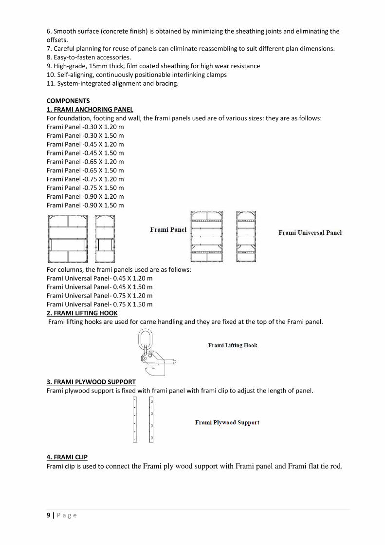
1. FRAMI ANCHORING PANEL
For foundation, footing and wall, the frami panels used are of various sizes: they are as follows:
Frami Panel -0.30 X 1.20 m
Frami Panel -0.30 X 1.50 m
Frami Panel -0.45 X 1.20 m
Frami Panel -0.45 X 1.50 m
Frami Panel -0.65 X 1.20 m
Frami Panel -0.65 X 1.50 m
Frami Panel -0.75 X 1.20 m
Frami Panel -0.75 X 1.50 m
Frami Panel -0.90 X 1.20 m
Frami Panel -0.90 X 1.50 m
For columns, the frami panels used are as follows:
Frami Universal Panel- 0.45 X 1.20 m
Frami Universal Panel- 0.45 X 1.50 m
Frami Universal Panel- 0.75 X 1.20 m
Frami Universal Panel- 0.75 X 1.50 m
2. FRAMI LIFTING HOOK
Frami lifting hooks are used for carne handling and they are fixed at the top of the Frami panel.
3. FRAMI PLYWOOD SUPPORT
Frami plywood support is fixed with frami panel with frami clip to adjust the length of panel.
4. FRAMI CLIP
Frami clip is used to connect the Frami ply wood support with Frami panel and Frami flat tie rod.

10 | P a g e
5. FRAMI ALIGNING CLAMP
Frami aligning clamp is used for aligning the panels and they are fixed with Frami panel.
6. FRAMI UNIVERSAL WALLING
Frami universal walling is used at the panel joints in the vertical direction with wedge clamp. It is
available in two sizes, 0.65m and 0.75m.
7.FRAMI INSIDE CORNER
Frami inside corner is Used to form inside corner. It is available in two sizes, i.e- 1.20m and
1.50m.
8. FRAMI OUTSIDE CORNER
Frami outside corner is used to form outside corner. It is available in two sizes: 1.20m and
1.50m.
9. SUPERPLATE
Used as a bearing plate for tightening of tie rod.

11 | P a g e
10. FRAMI CLAMP
Used to connect the Frami panels together.
11. FRAMI ADJUSTABLE CLAMP
Used to adjust the gap between the panels and they are fixed in the horizontal direction of
the panels.
12.FRAMI ADJUSTING STRUT
Used to align the panels in line and verticality.
13. TIE ROD
Tie rod is used for tieing purpose.
14. HEAD ADAPTER
It is used to fix the CT prop with aluform waler to transform the load.
15. ALUFO WALER
Aluform waler is used in Aluform system formworks to provide strength to aluform plates or aluform
frames.
Aluform Waler

12 | P a g e
16.WING NUT
Wing nut is used to fix the tie rod.
17. H beams
Timber and steel H beams are used for column supporting system along with alufo walers.
H beams are mainly of two sizes H-16 and H-20.
18. WATER BARRIER DISC
Water barrier disc is a component of Water retaining structure formwork which prevents the
penetration of water into the concrete structure.
19. TIE ROD ACCESSORIES
With tie rod, the accessories that are used to protect the tie rod for it can be used again preventing the
slurry loss., are:
i) Tie rod cone
ii) Tie rod cone plug
iii) Tie rod tube
iv) Tie rod tube plug

13 | P a g e
3.. HEAVY DUTY TOWER
FEATURES
1. For slab and beam formwork with tall staging heights and heavier loading, capacity is 250 KN needing
bracing at every 6m in height in both horizontal directions with permanent structure and other towers.
2. Tower can be assembled in plan dimensions of 1524 mm x 1524 mm and 2250 mm x 1524 mm, by
choosing the type of bracing, both configurations with four legs of 62.5 KN each.
3. Additional frames can be attached to towers to give twin tower configuration
4. Height adjustments up to a maximum of 800 mm is possible by utilizing both top and bottom tower
spindles
5. Easy to obtain plumb using tower spindles at bottom
6. Inclined decking is also possible using tower spindles on top
7. Individual components are light enough to be handled manually for erection and dismantling though
tower as a single unit can be handled when crane is available
8. Tower as a whole can be shifted (rolled) manually by attaching transport devices to the legs.
9. HDT system can also be used to construct staircase.
COMPONENTS
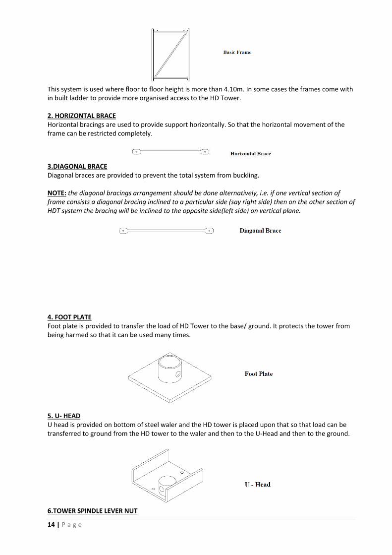
1.BASIC FRAME
Basic frame of Heavy duty tower system are of three sizes:
i)0.90m
ii)1.20 m
iii)1.80 m
14 | P a g e
This system is used where floor to floor height is more than 4.10m. In some cases the frames come with
in built ladder to provide more organised access to the HD Tower.
2. HORIZONTAL BRACE
Horizontal bracings are used to provide support horizontally. So that the horizontal movement of the
frame can be restricted completely.
3.DIAGONAL BRACE
Diagonal braces are provided to prevent the total system from buckling.
NOTE: the diagonal bracings arrangement should be done alternatively, i.e. if one vertical section of
frame consists a diagonal bracing inclined to a particular side (say right side) then on the other section of
HDT system the bracing will be inclined to the opposite side(left side) on vertical plane.
4. FOOT PLATE
Foot plate is provided to transfer the load of HD Tower to the base/ ground. It protects the tower from
being harmed so that it can be used many times.
5. U- HEAD
U head is provided on bottom of steel waler and the HD tower is placed upon that so that load can be
transferred to ground from the HD tower to the waler and then to the U-Head and then to the ground.
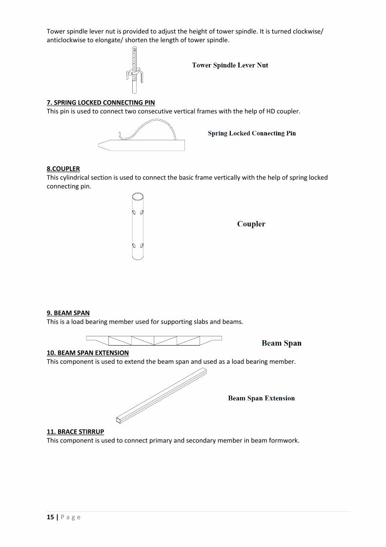
6.TOWER SPINDLE LEVER NUT
15 | P a g e
Tower spindle lever nut is provided to adjust the height of tower spindle. It is turned clockwise/
anticlockwise to elongate/ shorten the length of tower spindle.
7. SPRING LOCKED CONNECTING PIN
This pin is used to connect two consecutive vertical frames with the help of HD coupler.
8.COUPLER
This cylindrical section is used to connect the basic frame vertically with the help of spring locked
connecting pin.
9. BEAM SPAN
This is a load bearing member used for supporting slabs and beams.
10. BEAM SPAN EXTENSION
This component is used to extend the beam span and used as a load bearing member.
11. BRACE STIRRUP
This component is used to connect primary and secondary member in beam formwork.

16 | P a g e
12. SHORT PROP
This component is connected with steel waler for slab formwork.
4. BEAM FORMING SUPPORT
FEATURES
1. For beam formwork with minimum beam depth of 300 mm excluding slab thickness (can be
used for beams of less depths if packing is given in beam bottom and making it up to 300 mm)
i.e. with minimum side formwork height of 300 mm.
2. Uses standard components avoiding skilled making at site.
3. Requires no form ties up to a total beam depth of 900 mm including slab thickness, though use
of ties may increase the spacing of beam forming supports.
4. Arrangement on sides remains independent of beam width.
5. Adjustability in side formwork height in 10 mm intervals.
6. Side formwork remains perpendicular to beam bottom.
7. Easy assembling, aligning, fixing and dismantling.
COMPONENTS
1.BEAM FORMING HEAD SUPPORT
To support the beam side.
2. ADJUSTABLE BEAM SIDE EXTENSION
To support the beam side ply wood wherever space is more than the requirement.

17 | P a g e
3. BEAM FORMING SUPPORT EXTENSION
To adjust the beam depth where required.
This component is available on variable sizes:
0.6m H-20
0.8m H-20
1.0m H-20
1.2m H-20
0.6m H-16
0.8m H-16
1.0m H-16
1.2m H-16
4. STAIR GRIP NUT
To adjust the beam forming support with H beam.

18 | P a g e
ACCESS SCAFFOLDING
FEATURES
1. Exclusively used for scaffolding purposes up to 40 m height, braced at every 6 m with structure
2. Uses lighter frames compared to those in Heavy Duty Tower staging
3. This provides free movement for workmen without any obstruction at all levels
4. Frames with legs 1 m apart are spaced at 2.25 m intervals with 2.25 m long standard bracings (H-225
and 2H-225)
5 Bracing 2H-225 serves as an essential bracing for stability as well as handrail on the face away from
the structure.
COMPONENTS
1. SCAFFOLD FRAME
Scaffold frame acts as a basic frame for access purpose.
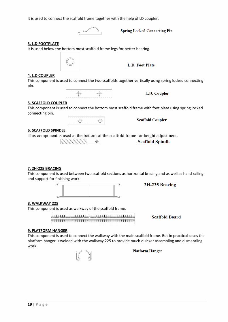
2. SPRING LOCKED CONNECTING PIN
19 | P a g e
It is used to connect the scaffold frame together with the help of LD coupler.
3. L.D FOOTPLATE
It is used below the bottom most scaffold frame legs for better bearing.
4. L.D COUPLER
This component is used to connect the two scaffolds together vertically using spring locked connecting
pin.
5. SCAFFOLD COUPLER
This component is used to connect the bottom most scaffold frame with foot plate using spring locked
connecting pin.
6. SCAFFOLD SPINDLE
This component is used at the bottom of the scaffold frame for height adjustment.
7. 2H-225 BRACING
This component is used between two scaffold sections as horizontal bracing and as well as hand railing
and support for finishing work.
8. WALKWAY 225
This component is used as walkway of the scaffold frame.
9. PLATFORM HANGER
This component is used to connect the walkway with the main scaffold frame. But in practical cases the
platform hanger is welded with the walkway 225 to provide much quicker assembling and dismantling
work.

20 | P a g e
STAIR TOWER
FEATURES
1. Safe and convenient access up to 100 m height in the form of stair with suitable bracing with
permanent structure every 6 m
2. Structural skeleton of Heavy Duty Tower with a few additional accessories
3. Can be handled as a single unit a crane
COMPONENTS
1. STAIR BRACKET
The stair brackets provide main supporting structure of the staircase. There are two types of stair
brackets used in each of the staircase sections
i) Stair Bracket 225 left
ii) stair bracket 225 right
they are used to fix grid iron rails.

21 | P a g e
2. INTERMEDIATE RAILING
Intermediate railings are used as handrails in inner side of stair tower.
3. INNER HAND RAILING
Fixed in vertical direction with stair bracket and used as inner hand railing.
4. CONNECTION ANGLE 225
Used for fixing the bracings / handrails in external face of the stair tower. On the connection angles
there are some clamps, which when kept open, the bracings can be removed and in closed position
work can be safely carried out as they are locked in that position.
5. GRID IRON
It is fitted with stair bracket and used for stepping purpose. These sections are fastened to the brackets
by means of nut and bolt.

22 | P a g e
USE OF FORMWORK COMPONENTS
Using all the formwork components a scheme drawing is provided. According to
the scheme drawing, the formwork should be arranged at site.
GRID MARK
TRIPOD
H BEAM
CT 410 PROP
SCHEME DRAWING

23 | P a g e
TOOLS AND TACKLES REQUIRED
The tools and tackles required for formwork can be broadly classified into three types as
1. Tools and tackles
2. Consumables
3. Safety appliances
1. COMMON TOOLS AND TACKLES FOR MAKING, FIXING AND REMOVING a. Hammers – Claw hammer, Ball pin hammer
b. Saw – Hand saw, Tenonsaw, Hacksaw frame with blade, potable
c. circular saw
d. Planner – Wooden jack planner, Iron jack planner, potable planner
e. Gauge – Wooden Marking gauge, Wooden mortise gauge
f. Spirit level, Tri-square, Auger, Measuring tape
g. Chisel - Framer chisel, Mortise chisel
h. Cutting player, Screw driver, Star screw driver.
i. Marking knife / Scribe, Wooden mallet, oil stone (Rough / smooth)
j. Cutting chisel, center punch
k. Bench vice, Jumper bit, Bench grinder
l. File – Triangle file, Half round file and flat file
m. Drilling machine, Drill bit
n. Plumb bob, Water tube level
o. Spanners – Ring spanners, Double end spanners, screw spanners,
p. Adjustable spanner
q. Tools kit
r. Plywood
s. Shuttering plywood
(i) Boiling Water Proof Plywood (BWP)
(ii) Boiling Water Resistance Plywood (BWR)
(iii) Film coated plywood
(iv) Densified film coated plywood
(v) Commercial plywood
2. SAFETY APPLIANCES a) Safety goggles
b) Safety helmet
c) Cotton hand gloves
d) Safety belt
e) Face mask
f) Leather Apron
g) Safety shoes
h) Ear muff
3. CONSUMABLES a. Wire nails
b. Shutter releasing agent
c. Cotton waste.
24 | P a g e
QUALITY ASSURANCE
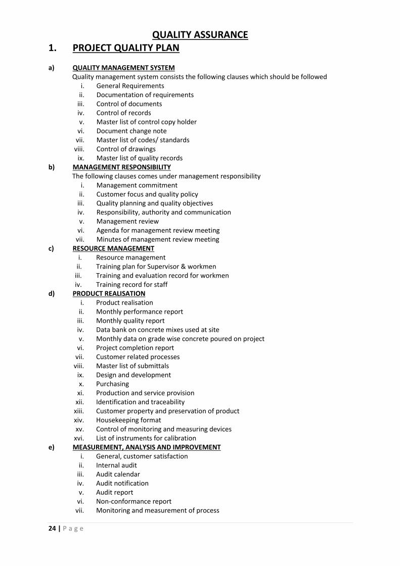
1. PROJECT QUALITY PLAN
a) QUALITY MANAGEMENT SYSTEM
Quality management system consists the following clauses which should be followed
i. General Requirements
ii. Documentation of requirements
iii. Control of documents
iv. Control of records
v. Master list of control copy holder
vi. Document change note
vii. Master list of codes/ standards
viii. Control of drawings
ix. Master list of quality records
b) MANAGEMENT RESPONSIBILITY
The following clauses comes under management responsibility
i. Management commitment
ii. Customer focus and quality policy
iii. Quality planning and quality objectives
iv. Responsibility, authority and communication
v. Management review
vi. Agenda for management review meeting
vii. Minutes of management review meeting
c) RESOURCE MANAGEMENT
i. Resource management
ii. Training plan for Supervisor & workmen
iii. Training and evaluation record for workmen
iv. Training record for staff
d) PRODUCT REALISATION
i. Product realisation
ii. Monthly performance report
iii. Monthly quality report
iv. Data bank on concrete mixes used at site
v. Monthly data on grade wise concrete poured on project
vi. Project completion report
vii. Customer related processes
viii. Master list of submittals
ix. Design and development
x. Purchasing
xi. Production and service provision
xii. Identification and traceability
xiii. Customer property and preservation of product
xiv. Housekeeping format
xv. Control of monitoring and measuring devices
xvi. List of instruments for calibration
e) MEASUREMENT, ANALYSIS AND IMPROVEMENT
i. General, customer satisfaction
ii. Internal audit
iii. Audit calendar
iv. Audit notification
v. Audit report
vi. Non-conformance report
vii. Monitoring and measurement of process

25 | P a g e
viii. Work Instruction for product quality rating
ix. CONQAS manual
x. Control of non-conforming product
xi. Analysis of data
xii. Improvement
xiii. Corrective action
xiv. Preventive action
CONQAS (Construction Quality Assesment System)
It is provided to
I. To have a standard assessment system for construction project
II. To make quality objective by
- Measuring constructed works against workmanship standards and specification
- Using a sampling approach to suitably represent the whole project
- To enable quality assessment to be carried out systematically with reasonable
cost and time.
2. FIELD ASSURANCE PLAN
A. METHOD STATEMENT Method statement is the list where the method of any work is described so that safe and
quality work is assured by the engineer, supervisor and workers. According to method
statement any work is carried out and the work is checked afterwards. A sample of the method
statement of WBHIDCO BISWA BANGLA CONVENTION CENTRE is given here.
Objective: -
i. Construct brickwork lines, positions, plumbs etc. as required by good practices
ii. Tolerance to position- -/+ 5mm. Straightness 5mm in 3000mm. Plumb 5mm in3000mm.
Dimension +5mm in plan.
Reference
A. Relevant GFC drawings
B. Technical Specifications
C. Inspection and test plan
D. IS 1077, IS 2212

26 | P a g e
SL
NO. PROCEDURE RESPONSIBILITY CHECKED BY
1
Select, stack bricks conforming to IS-1077 with
first class quality table moulded chamber burnt
bricks with a minimum crushing strength of 105
kg/cm2
QA/QC Engg. QA/QC Engg.
2 Mark line on floor for dimensions, check w.r.t
drawing Finishing engg. QA/QC Engg.
3 Hack columns or concrete faces where brick work
will abut Finishing engg. QA/QC Engg.
4
Mix sand cement of specified proportions (mixed
mortar to be used within 30 minutes) Mix for 250
mm brick work shall be 1:6 and for 125mm thick
wall shall be 1:4
Finishing engg. QA/QC Engg.
5
Construct first layer keeping the joint uniform and
thickness of joint shall not exceed 10mm. Check
dimensions, bonding etc. Ensure opening
dimensions.
Finishing engg. QA/QC Engg.
6
Brickwork shall be laid in English bond only. Work
shall be proceeded further and checked at regular
intervals
Finishing engg. QA/QC Engg.
7 Outer surface of the brickwork shall be kept even Finishing engg. QA/QC Engg.
8 For 125mm thick brickwork HB netting is to be
provided for every third layer of brickwork. Finishing engg. QA/QC Engg.
9
Build B/W in layers not exceeding 1000mm per
day. Constantly check plumb. Rake joints to
100mm deep.
Finishing engg. QA/QC Engg.
10
Leave the top layer of brickwork abutting the
soffit of beams with open joints- to allow the
beam to sag.
Finishing engg. QA/QC Engg.
11
At inter connected brickwork shall be carried out
at the same time. Where it is not possible, the
brickwork shall be raked back in a bone and saw
tooth pattern at an angle not exceeding 45°
Finishing engg. QA/QC Engg.
12 Paint construction dates Finishing engg. QA/QC Engg.
13 Cure for seven days Finishing engg. QA/QC Engg.

27 | P a g e
B.TEST REPORTS If any test is needed to be conducted, it should be documented properly in a report. The complete
test results are kept in the lab test reports. They are conducted at site QC lab itself or may be done
by third parties.
A sample of the brick test report is as follows:
BRICK TEST REPORT Supplier:
Brand:
Type:
Date:
Sl no. Brick Id Breadth Length Depth Area(mm2) Load (KN)
Strength
(N/mm2)
1
2
3
4
5
C.CHECKLISTS
Checklists are the record of any work if the work is done correctly, if any actions needed etc.
According to checklist any work is evaluated. The deviation of required work and actual work (if
there is any) can be clearly seen on the checklists. Checklists for reinforced concrete works are also
called as POUR CARD.
A sample of checklist is as follows:
CHECK FOR MASONRY WORK Area/ Building: Date:
Location:
Description of work/ Drawing Reference:
A Specifications Check Required Actual Remarks
1 Type of masonry- Brick/Block
2 Bricks/Blocks soaked in water
3 Ratio of Mortar
B Process Check
1 Marking of walls at floor
2 Plumb check –Initial
3 Raking of joints/ Joint thickness
4 Doors and window openings
5 Reduced level of sill/lintel/bottom
6 MEP services/ Embedment
7 Plumb check-final
NOTE: Record typical dimension check on reverse

28 | P a g e
QUALITY CONTROL Based on quality assurance report and the modifications done, strict quality control can be followed
on site. The processes approved are used to execute any work. The effective documents which
are used in case of execution are,
1. Method Statement: Is followed by Site engineers as well as supervisors to check and
execute the work in a proper way. Proper following of this document ensures safe and
quality work.
2. Inspection Test Plan: It is followed by both site engineer and quality engineer
3. Checklist: Checklist is filled up before every work done on site. Some samples of checklists
are as follows:
Concrete works checklist (Pour card)

29 | P a g e
Checklist for brickwork
30 | P a g e
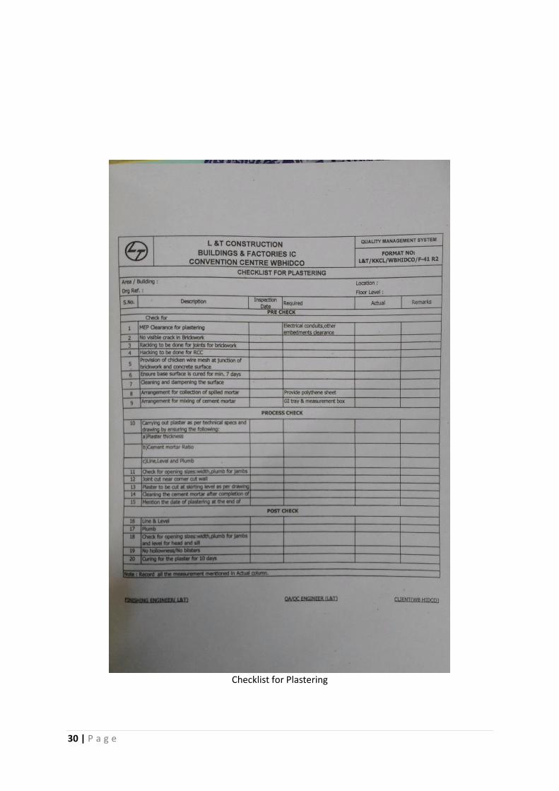
Checklist for Plastering

31 | P a g e
SITE SUPERVISION In terms of quality control, site supervision is a very important aspect. The quality control engineer
assigned should check the day to day work performed in site and take adequate measures
accordingly. As a quality control engineer of civil engineering, the duties of an engineer are as
follows:
CONCRETING BEFORE CONCRETING
1. To check if all the work is done as per specification while the work is under progress / the
section of a work is completed.
2. To check if the alignment (both vertical and horizontal) of the structural members are as per
drawing specifications.
3. To check if the dimensions of the structural members are as per drawing specifications, if any
complexity arises he will contact with the planning department and further decisions should be
followed.
4. To check if the reinforcements are placed in proper positions of the structural members and
whether they are of correct diameter or not. If any deviation of the reinforcements happens
which is beyond the tolerance, he should report the matter to department and take adequate
measures.
5. To check if adequate cover is given on structural members.
6. To check if the formwork is correctly placed. Also if adequate/ quality products are used to
ensure that in time of concreting or later no problem arises due to the faulty formworks. If
there is any fault in the formwork, it should be replaced with the consent of the formwork
engineer.
7. To check if the reinforcements are bound properly with binding wires. If not, he/she should
tell the site engineer to redo it.
AFTER CONCRETING
It is the duty of quality engineer to check the area where concreting is done if the surface is
levelled as per drawing specifications. He should also check that if the surface of the member is
properly finished. He should also check that if there is bleeding of concrete.
BRICKWORK
BEFORE BRICKWORK
1. To check if proper tests of bricks are done and all bricks present in site for construction are
suitable for construction.
2. To check if the measuring box and other equipment are present during the brickwork.
3. To check if the hacking is done on the concrete member properly before brickwork is
commenced on that area where brickwork is to be connected with the concrete member.
AFTER BRICKWORK
1. To check if the brickwork is done according to architectural layout.
2. To check if the plumb and line of brickwork is as per drawing specifications.
3. To check if the H.B net is provided for 125 mm thick brick wall after consecutive three layers
of brickwork.
4. To check that proper raking is done.
5. To ensure that toothing is done where required and the faces of toothing are cleared of
mortar and other loose materials.
6. To ensure that the mortar thickness is as specified in Method Statement.

32 | P a g e
FINISHING WORK (PLASTERING) BEFORE PLASTERING
1. To check if proper raking is done.
2. To check if proper arrangement by gunny bags to collect cement plastering is done.
3. To check if proper access scaffolding for plastering works is provided.
4. To check if measuring box for plastering work is present.
5. To check if levelling instruments are present in site.
6. To check if the ratio of sand and cement for plastering work provided on document is ok.
AFTER PLASTERING
1. To check if the level of plaster is okay.
2. To check if H.B net is provided at the joint of concrete member and brickwork along the
length of the brickwork.
3. To check if the 90° corners are provided properly.
IPS FLOORING BEFORE FLOORING
1. To check if the surface is prepared properly by removing debris and loose materials.
2. To check if the aluminium strips are placed properly to form the panels and also check the
dimensions of panel so that it is not greater than 2 m 2 and also dimension on any side is not
greater than 2 m.
3. To check if the grade of concrete supplied is correct.
4. To check if the corner beads placed are according to level.
5. To ensure proper formwork is provided.
AFTER FLOORING
1. To check if levelling is done properly with the help of power trowel.
2. To ensure that proper finishing of surface is done.
3. To ensure that after removal of shuttering, the joints of reinforced concrete and IPS are
finished by mortar well.
QUALITY CONTROL LAB
To maintain good quality control, sample of every material is checked on quality control lab and
the they are declared as GFC Good For Co structio aterials. The they are supplied i bulk and the construction is done accordingly.
The materials which are tested are:
1. Bricks
2. Fine aggregates
3. Coarse aggregates
4. Cements
5. Reinforcements
6. Woods
7. Tiles
and others test of the following materials are done
1. Concrete
2. Mortar

33 | P a g e
The list of tests done at WBHIDCO BISWA BANGLA CONVENTION CENTRE are as follows:

34 | P a g e
Tests performed under supervision of Mr. Amar Gupta at site QC Laboratory are:
1. Compressive Strength test of brick
2. Compressive strength Test of Mortar Cube
3. Slump test for workability at batching plant
1. TEST FOR DETERMINING THE COMPRESSIVE STRENGTH OF CLAY BRICKS
PURPOSE OF TESTING:
This test is done for determining the compressive strength of clay bricks.
IS REFERENCE:
IS: 5454-1976 Method of sampling of clay bricks
IS: 3495-1992 (Part-I) Methods of tests of burnt clay building bricks
PRINCIPLE:
This test starts by applying compressive force to a brick by compression testing machine, generally
to fracture, for the purpose of deter i i g it’s co pressive stre gth.
TEST EQUIPMENTS:
Compression Testing Machine
Compression Plate
TEST PROCEDURE:
Place the specimen with flat faces horizontal and sand filled face facing upwards between 3
plywood sheets each of 3mm thickness and centered between plates of testing machine
Apply load axially at rate of 14N/mm2 per minute till failure occurs and note the maximum
load at failure
Repeat this process for 5 specimen and calculate the average strength of six bricks.
CALCULATION:
Compressive strength in N/mm2
Maximum Load at failure in N (kgf)
(kgf/cm2) =
Average area of the bed faces in mm2 (cm
2)
ACCEPTANCE CRITERIA:
The crushing strength of bricks for different type of work shall be as follows:
a) For load bearing brick walls - 105 kg/cm2
or as specified in the schedule of items but not less than
75kgs/cm2.
b) For non load bearing - 75kg/cm2 to 50kg/cm
2
brick walls
c) For soling - 100kg/cm2 to 75kg/cm
2
(Picked Jhama Bricks)
35 | P a g e
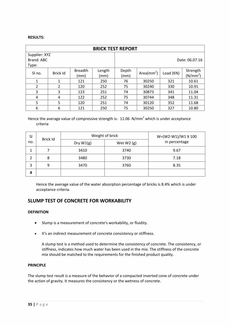
RESULTS:
BRICK TEST REPORT Supplier: XYZ
Brand: ABC
Type:
Date: 06.07.16
Sl no. Brick Id Breadth
(mm)
Length
(mm)
Depth
(mm) Area(mm
2) Load (KN)
Strength
(N/mm2)
1 1 121 250 76 30250 321 10.61
2 2 120 252 75 30240 330 10.91
3 3 123 251 74 30873 341 11.04
4 4 122 252 75 30744 348 11.31
5 5 120 251 74 30120 352 11.68
6 6 121 250 75 30250 327 10.80
Hence the average value of compressive strength is- 11.06 N/mm2 which is under acceptance
criteria
Sl
no. Brick Id
Weight of brick W=(W2-W1)/W1 X 100
in percentage Dry W1(g) Wet W2 (g)
1 7 3410 3740 9.67
2 8 3480 3730 7.18
3 9 3470 3760 8.35
4
Hence the average value of the water absorption percentage of bricks is 8.4% which is under
acceptance criteria.
SLUMP TEST OF CONCRETE FOR WORKABILITY
DEFINITION
Slump is a measurement of concrete's workability, or fluidity.
It's an indirect measurement of concrete consistency or stiffness.
A slump test is a method used to determine the consistency of concrete. The consistency, or
stiffness, indicates how much water has been used in the mix. The stiffness of the concrete
mix should be matched to the requirements for the finished product quality.
PRINCIPLE
The slump test result is a measure of the behavior of a compacted inverted cone of concrete under
the action of gravity. It measures the consistency or the wetness of concrete.
36 | P a g e
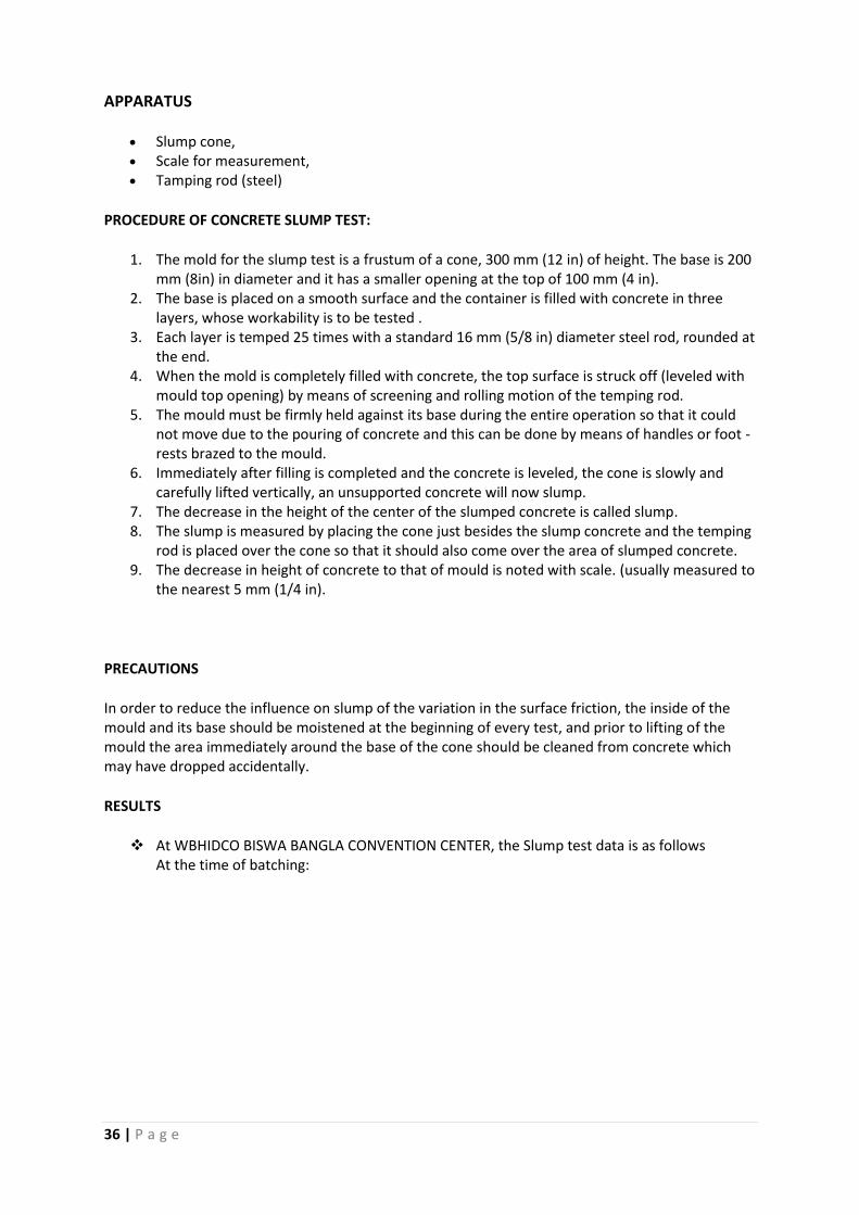
APPARATUS
Slump cone,
Scale for measurement,
Tamping rod (steel)
PROCEDURE OF CONCRETE SLUMP TEST:
1. The mold for the slump test is a frustum of a cone, 300 mm (12 in) of height. The base is 200
mm (8in) in diameter and it has a smaller opening at the top of 100 mm (4 in).
2. The base is placed on a smooth surface and the container is filled with concrete in three
layers, whose workability is to be tested .
3. Each layer is temped 25 times with a standard 16 mm (5/8 in) diameter steel rod, rounded at
the end.
4. When the mold is completely filled with concrete, the top surface is struck off (leveled with
mould top opening) by means of screening and rolling motion of the temping rod.
5. The mould must be firmly held against its base during the entire operation so that it could
not move due to the pouring of concrete and this can be done by means of handles or foot -
rests brazed to the mould.
6. Immediately after filling is completed and the concrete is leveled, the cone is slowly and
carefully lifted vertically, an unsupported concrete will now slump.
7. The decrease in the height of the center of the slumped concrete is called slump.
8. The slump is measured by placing the cone just besides the slump concrete and the temping
rod is placed over the cone so that it should also come over the area of slumped concrete.
9. The decrease in height of concrete to that of mould is noted with scale. (usually measured to
the nearest 5 mm (1/4 in).
PRECAUTIONS
In order to reduce the influence on slump of the variation in the surface friction, the inside of the
mould and its base should be moistened at the beginning of every test, and prior to lifting of the
mould the area immediately around the base of the cone should be cleaned from concrete which
may have dropped accidentally.
RESULTS
At WBHIDCO BISWA BANGLA CONVENTION CENTER, the Slump test data is as follows
At the time of batching:

37 | P a g e
SAMPLE-1:
Prepared For- Slab Casting at Main Building
Grade- M25
Slump at the time of batching- 190mm (COLLAPSE)
SAMPLE-2
Prepared For- Column in Main Building
Grade- M35
Slump at the time of batching- 150mm (True Slump)

38 | P a g e
TEST PROCEDURE FOR COMPRESSIVE STRENGTH TEST OF
CONCRETE SPECIMENS PURPOSE OF TESTING:
This test is done to determine compressive strength of concrete specimens.
BIS REFERANCE:
IS 516 : Methods of test for strength of concrete
IS 1199 : Method of sampling and analysis of concrete
TEST EQUIPMENTS:
Compression Testing Machine 3000 kN
Compression Testing Machine 1000 kN
Compression Testing Machine 500 Kn
Cube (15x15x15) & (10x10x10) cm3 & Cylinder (15x300)
Above Testing Machine should regularly calibrate at every three month intervals.
AGE AT TEST:
Test is conducted at recognized ages of the test specimens, the more common being 7 & 28
days.
The age is calculated from the time of addition of water to the dry ingredients.
NUMBER OF SPECIMENS:
At least three specimens is required for testing at each specified age.
TEST PROCEDURE:
Specimens are to be stored in water & should test immediately on removal from the water &
should maintain the wet condition until testing.
Bearing surface of testing machine should wipe clean & the loose materials from the surface
of specimens also removed.
Cube specimens should be placed in such manner that the load shall be applied to opposite
sides as it cast.
The axis of the specimens shall be carefully aligned with the center of the thrust.
The pace rate is to be set to 5.2 kN/Sec for 15cm cube & 4.0 kN/Sec for 15 cm dia cylinder.
The maximum load applied to the specimen shall be recorded.
CALCULATIONS:
The measured compressive strength of the specimen = P/A ( Kg/cm2,N/mm2or MPa)
P = Max load applied to the specimen during the test
A = Cross sectional area of the specimen
Average of three values is taken as representative of the batch.
Individual variation should not be more than + 15 % of the Average.

39 | P a g e
ACCEPTANCE CRITERIA:

40 | P a g e
RESULT:
The compressive strength test result with respect to grades of concrete are as follows:
Location of
Pour Grade Cement
Slump
(mm) at
the time
of batch
Id Weight
(kg) Age
7days result 28 days result
Ind Avg Ind Avg
Mini
auditorium
column
M30 PPC 175
1 8.630
7
25.78
2 8.670 25.69 25.91
3 8.680 26.27
4 8.610
28
34.80
5 8.630 34.58 35.16
6 8.620 36.09
Annex
building
staircase
(ST-2)
M25 PPC 160
1 8.590
7
20.98
2 8.580 20.35 20.75
3 8.600 20.93
4 8.580
28
33.02
5 8.590 33.64 32.80
6 8.580 31.73
Main
Building Slab M25 PPC 170
1 8.520
7
19.20
2 8.540 20.00 19.70
3 8.530 19.91
4 8.590
28
30.53
5 8.610 30.71 31.08
6 8.540 32.00
CONCLUSION
The strength achieved by the concrete cubes at 7 and 28 days are as per Table 2 of IS 456:2000.
Hence the mix design of concrete is ok.

41 | P a g e
REINFORCED CONCRETE WORKS
REINFORCED CONCRETE PILECAP
Pile cap is a structure which is provided above piles to distribute the load of column properly on the
foundation.
In WBHIDCO STATE CONVENTION CENTRE, the piles used are reinforced concrete piles. The
specifications are as follows.
a. The concrete grade is M-25
b. Slump is 120mm
c. Column formwork system is used Alufo system.
CHECKING OF PILECAPS
1. If the reinforcement provided are according to B.B.S and reinforcement drawing.
2. If the alignment f pile cap is right.
3. If the plumb level of the pilecap is right.
4. If the dimension of pile cap is right and according to scheme drawing.
5. If adequate cover has been provided.
6. If the plywood have been sprayed with the lubricant.
7. If the condition of plywood is okay.
8. If the formwork components has been given according to scheme drawing.
EXECUTION OF R.C.C PILE CAP WORKS
Execution work carried is the responsibility of site engineer and he should assess the problems and
monitor day to day work carried by so that productivity of the work is not hampered along with EHS.
1. Cutting of soil is done by
2. Alig e t of pilecap is do e as per surveyor’s i structio . 3. If any deviation of pile has happened during piling, accordingly the pile dimension should be
redesigned/assigned by consultation with in-charge.
4. After the alignment, Reinforcements are tied according to reinforcement drawing, B.B.S and
it should be checked by reinforcement engineer. The column reinforcements are left from
pilecap providing adequate development length.
5. After the reinforcements are placed. Formwork is arranged as per scheme drawing.
6. After the formwork is arranged it should be checked by Formwork Engineer.
7. After completion of each stage, The ITP and checklist should be followed.
8. After successful submission of Pour card, the concreting is done.
9. After 16-24 hours of completion of concreting work is done, the formwork is removed.
10. Where needed, pilecap should be covered by waterproofing membrane (sika) and followed
by Geotextile sheet to protect the wateroroofing membrane.
11. The backfilling of soil by is done after hardening of the pilecap and construction of column
from it.
REINFORCED CONCRETE SLAB
Reinforced concrete slab is the primary component where the loads are applied first and then
transferred to the beams and columns.
In WBHIDCO BISWA BANGLA CONVENTION CENTRE, the slabs used are R.C.C normal slabs
with varying depth of 250mm-350mm
Some specification for the slab construction system are as follows:
Flex system is used mostly.
M-25 Concrete is used.
Where there is an opening in slab (MLCP RAMP AREA) and ultimately it closes down on top
floor then HDT system has been used.
Chairs are provided to keep the top and bottom layer of the slab different.

42 | P a g e
Welding of reinforcements are done where needed.
Repropping is done after 7 days and complete removal of shuttering is done after 14 days.
Concreting is done with the help of R.M.C truck, concrete pump and pipe assembly or
Concrete hopper and tower crane. In some cases direct pumping from concrete plant is also
done.
Formwork repetition technique is adopted. Hence repropping is very important.
CHECKING OF R.C.C SLAB
During the checking of R.C.C slab the following points should be checked
1. If the alignment and level of the slab formwork is right.
2. If the dimensions of the slab are right.
3. If Relative position of slab from beam is right.
4. If adequate cover is provided.
5. If the reinforcement dia is correct and main & distribution reinforcements are correctly
provided.
6. If the spacing between the reinforcements are okay.
7. If the provided development length is okay.
8. If L/U hook is provided at the right place.
9. If the formwork is sealed properly. Otherwise slurry loss may happen.
10. If the formwork plywood is in good condition. If not good, whether it is usable with the help
of pvc plug?
11. If chairs are provided adequately.
12. If MEP items are at place.
EXECUTION OF R.C.C SLAB
The entire process should be monitored by Site engineer and it is his responsibility to carry the
works needed and asses the problems as quickly as possible to find a quicker solution.
1. The formworks are arranged as per scheme drawing.
2. The reinforcements are arranged as per scheme drawing.
3. MEP works are carried out as per specifications.
4. Checking is done and ITP and Pourcard is filled.
5. Concreting is done.
6. Levelling is done.
7. Formwork removal is done after 7 days with adequate props. Which are removed after
14 days.
8. Adequate curing is done.
CONSTRUCTION JOINT
For monolithic construction, when the slab altogether cannot be poured together, then a
construction joint is created between the old pouring and the new pouring. The joints can be done
either at L/3 or 2L/3 where L = the span of the slab. To seal the joints so that no water penetrates
the joint, some chemicals are used.
At WBHIDCO BISWA BANGLA CONVENTION CENTRE the chemical which is used to seal the
construction joints is Sika waterproofing chemical.
The joints are kept vertical and not 45°. The explanation behind it from the Site engineer at
MLCP 2.26m level was: We provide the construction joint at L/3 or 2L/3 because point of
contraflexure is on that point in case of continuous slabs. It means the SF is maximum and
B.M is either zero or changing its sign so deflection is also minimum. Hence it is most safe
to provide construction joint at that place. Now why not 45°? Why vertical? It is a very
common practice to provide 45° joints between engineers. But as SF is maximum, if in any
case there is a slight chance of the slab failing due to shear, the fail will happen along that
45° crack which we have already provided. So now if we provide the joint vertically and use
proper waterproofing solution, we can eventually prevent any kind of risk.

43 | P a g e
EXECUTION
Execution work carried is the responsibility of site engineer and he should assess the problems and
monitor day to day work carried by so that productivity of the work is not hampered along with EHS.
The process of execution is as follows:
1. Construction joint is left while casting of a slab.
2. Before casting of the rest of the part of the slab, the loose materials are hacked and the hard
concrete surface is exposed.
3. The joint is sealed while casting the rest of the part of the slab by sika waterproofing
material.
REINFORCED CONCRETE BEAM
Reinforced concrete beam is an important structural member of the framed structure. It carries the
load from slab and transfers it to the column.
At WBHIDCO BISWA BANGLA CONVENTION CENTRE the R.C.C beams are of various
dimension and depth. The specifications and specialities of the R.C.C Beams seen on the site
are as follows:
1. The beams are not always Horizontally parallel. Beside the inclined slabs and long
span Staircase (MLCP) the beams are inclined.
2. At MLCP building the beam on the top slab is circular with a uniform cross section.
3. There are cranks provided on the beams to allow the main reinforcements of beam
to pass through at beam column junctions.
4. Where the reinforcement is cut, a lapping length of 50D should be provided.
5. A cover of 25 mm is provided for the beams.
6. Beams greater than 500mm in depth should be reinforced with side-face
reinforcements.
CHECKING OF R.C.C BEAM
The following factors should be checked while checking of R.C.C beams.
1. If the beam formwork is on aligned and positioned correctly.
2. If the beam formwork is as per scheme drawing.
3. If the formwork is sealed properly. Otherwise slurry loss may happen.
4. If the top and bottom reinforcement dia and numbers are correct.
5. If the size of stirrups are correct.
6. Stirrups are provided with alternate openings.
7. If adequate cover is provided.
8. If the spacing of stirrups are as per drawing.
9. If adequate development length is provided.
10. If reinforcement provided at beam column junction is correct according to junction detailing.
11. If formwork is in good condition and if the holes are sealed by PVC caps.
12. If the formwork boards are lubricated before concreting.
EXECUTION OF R.C.C BEAMS
Execution work carried is the responsibility of site engineer and he should assess the problems and
monitor day to day work carried by so that productivity of the work is not hampered along with EHS.
The steps for execution of an R.C.C Beam is as follows.
1. As per B.B.S the reinforcement cutting and bending is done.
2. As per scheme drawing formwork is done.
3. The reinforcement cage is placed inside the formwork.
4. Adequate cover is provided.

44 | P a g e
5. Stirrups are placed and bound by binding wire.
6. Checking is done according to ITP and pour card is issued
7. Concreting with required slump is done.
8. Formwork is removed after 7 days with adequate reproping.
9. Props are removed after 14 days.
10. Adequate curing is done.
REINFORCED CONCRETE COLUMN
Column is the vertical structural member, by which the loads of the building is transferred to the
pilecap and then to the concrete piles.
At WBHIDCO BISWA BANGLA CONVENTION CENTRE there are mainly Five types of R.C.C
columns are used.
I. Rectangular Column (Main bldg, MLCP Bldg, Sub Station, Annexe Bldg)
II. Square column (Main bldg, MLCP Bldg, Sub Station, Annexe Bldg)
III. Circular Column (Main Bldg)
IV. Triangular Column (Main Bldg)
V. Mullion (Main Bldg, Annexe Bldg)
Mainly four grade of concrete are used for columns.
M-25 (MLCP and ANNEX BUILDING)
M-30 (MAIN BUILDING)
M-35 (ANNEX BUILDING)
M-40. (ANNEX BUILDING)
The circular columns used in main buildings are mainly for architectural as well as structural strength
aspect. Rectangular and square columns are mainly for the framed structure buildings. Mullion is
discussed in detail at brickwork section as it is associated with brickwork.
CHECKING OF R.C.C COLUMN
An R.C.C column should be checked for the following factors:
1. If the starter is placed in correct position.
2. If the base of the column is free from loose material.
3. If the reinforcement provided are of adequate dia.
4. If the Lateral tie dimensions are as per B.B.S.
5. Ties are provided with alternate openings.
6. If the cover is adequate.
7. If the formwork arrangement is as per scheme drawing.
8. If the formwork is sealed properly. Otherwise slurry loss may happen.
9. If the alignment of the column is correct.
10. If the access scaffoldings required to for concreting are correct and safe.
11. If concreting is to be done more than 1.8m height from 0-0 level, then safety harness is used
or not.
EXECUTION OF R.C.C COLUMN
Execution work carried is the responsibility of site engineer and he should assess the problems and
monitor day to day work carried by so that productivity of the work is not hampered along with EHS.
The process of execution of column is as follows:
1. Reinforcement cutting and bending is done as per B.B.S
2. The starter is placed in position.
3. Lapping of vertical reinforcement is done as per drawing.
4. Lateral ties are placed as per reinforcement drawing.
5. Formwork is placed as per scheme drawing.

45 | P a g e
6. Alignment is done correctly.
7. Column checking according to ITP and the Pourcard is issued.
8. Concreting is done by manually or using concrete pump.
9. Formwork is removed after 16-24 hours.
10. Adequate curing is done.
REINFORCED CONCRETE STAIRCASE
It is a structural member built to access multiple floors manually.
At WBHIDCO BISWA BANGLA CONVENTION CENTRE two types of staircase are observed by
me.
Small Span staircase (at all buildings)
Large span staircase (at MLCP)
CHECKING OF STAIRCASE
The following factors in case of staircase are to be checked:
1. If the alignment and level of landings are correct.
2. If the alignment of waist slab is correct.
3. If the rise and trade are of correct dimension.
4. If the development length of the main bars are provided as per drawing.
5. If the formwork is executed as per scheme drawing.
6. If the spacing of main and distribution bars are correct.
7. Where welding is done, if the loose welding materials are cleared thoroughly.
8. If all the MEP items are in place and placed correctly with sealed joints.
9. If adequate cover is provided
10. If adequate chair bars are provided to maintain separation of reinforcements.
11. If beam and slab relative depth is correct.
12. If the formwork is sealed properly. Otherwise slurry loss may happen.
EXECUTION OF STAIRCASE
Execution work carried is the responsibility of site engineer and he should assess the problems and
monitor day to day work carried by so that productivity of the work is not hampered along with EHS.
The process of execution is as follows:
1. B.B.S is prepared and the reinforcements are cut and bound as per specifications.
2. Formwork and reinforcement binding work is done as per scheme drawing and concrete
detailing drawings.
3. After completion of the binding work and providing cover, concrete is poured.
4. Formwork removal is done after 7 days along with reproping.
5. The concrete is cured adequately.
REINFORCED CONCRETE WALL
Reinforced concrete wall is provided where there is need to provide water retaining or earth
retaining structure. Where vertical loads are coming at a great extent.
At WBHIDCO BISWA BANGLA CONVENTION CENTRE at Boundary, MLCP building and at
the top of Annexe Building, R.C.C wall is provided.
M25 concrete is used.
CHECKING OF R.C.C WALL
1. If the formwork is provided as per scheme drawing.
2. If the superplates are tightened enough.
3. If the water barrier discs are provided.
4. If the reinforcements are placed correctly.
5. If the spacing of reinforcements are correct.

46 | P a g e
6. If the cover provided is adequate.
7. If the plywood is lubricated before pouring.
8. If the formwork is sealed properly. Otherwise slurry loss may happen.
9. If access scaffoldings are at right place and are safe.
EXECUTION OF R.C.C WALL
1. The formwork is done as per scheme drawing and the reinforcements are bound as per
concrete detailing.
2. Formwork is double checked for any leaks
3. All components are checked and if any component is loose it is tightened.
4. Concrete pouring is done.
5. Formwork is removed after 24 hours.
6. Adequate curing/ waterproofing with geotextile membrane is done.
REINFORCED CEMENT CONCRETE LINTEL
R.C.C Lintels are provided in the place of openings to bear the load of brick wall above. At WBHIDCO
BISWA BANGLA CONVENTION CENTRE, the bearing of lintel provided is 250mm. The checking and
execution is alike R.C.C beams. The difference is that the lintel is cast after construction of brickwork
upto a certain level.

47 | P a g e
FINISHING WORKS
BRICKWORK Brickwork is a component of finishing work. It decides the architectural skeleton of a building. So if
any deviation of concrete member happens, it can and must be corrected in case of brickwork.
Otherwise unnecessary cost and material wastage may happen.
In WBHIDCO BISWA BANGLA CONVENTION CENTRE two types of brickwork has been used
1. 125 mm thick brickwork
Cement : Sand= 1:4 (along with H.B Net)
2. 250 mm thick brickwork
Cement : Sand = 1:6
And the type of brick bond used is English Bond
METHOD OF EXECUTION THE BRICKWORK
1. Bricks should be tested and properly stacked at site. Before starting brickwork, bricks should
be properly wet so that it does not absorb water after laying mortar. This will ensure the
proper hydration of cement in mortar and hence providing adequate strength to brick wall.
2. According to grid lines, the alignment of the walls according to the architectural plan should
be done.
3. Hacking should be done at concrete surface @40-50 indents per sq.ft.
4. After providing the alignment, the layering of brickwork should be started.
5. 250 mm thick brickwork should be carried one after another layer using line thread and the
plumb level should be constantly checked after completion of each layer.
6. For 125 mm brickwork, after 3 consecutive layers of brickwork, H.B net should be provided.
This ensures the strength of the brick wall.
7. After each layer of brickwork construction, the thickness between two consecutive layers of
brickwork should be 10mm.
8. After completion of brickwork in each area raking of 15 mm should be done.
9. After completion of the brickwork, it should be checked by Supervisor, Finishing Engineer
and QC Engineer and the ITPs and checklists should be fulfilled.
SPECIAL MEASURES
Where the brickwork is more than general dimension in length and height, Special Reinforced
concrete band lintel and Columns should be provided.
1. Concrete Band Lintel
It is provided when the floor to floor height is more than 4m. The intervals between the lintels are
3m. Also when any parapet wall is provided at any heght more than 4m, Band lintel should be
provided.
Dimension: Breadth- 250mm, Depth 250mm or as specified
Place:
i. At 3m interval
ii. At the top of parapet wall
Process:
i. The Reinforced concrete column is drilled so that the lintel main reinforcements can be
grouted.
ii. The drilled holes are thoroughly cleaned by blowing them with blow pipes.
iii. Grouting agent (FISCHER) is filled on the hole.
iv. The reinforcements are inserted I n the hole and sealed.
v. The stirrups are placed according to drawing specifications.
vi. Formwork is provided.

48 | P a g e
vii. Concreting is done.
viii. Removal of formwork is done after 24 hours where there is support beneath the band lintel
(e.g. Parapet wall) or after 7 days with repropping where there is an opening beneath the
lintel.
ix. Curing is done adequately before removal of formwork.
2. Mullions (special R.C.C column)
Dimensions: Length 250mm , Breadth- 250mm
Place:
As per drawing specifications
Process:
i. Surface is cleaned thoroughly.
ii. The proper lapping of existing reinforcements of mullion are done.
iii. Reinforcements are provided as per drawing specifications (4-12mm tor).
iv. Formwork is provided.
v. Concreting is done.
vi. Removal of formwork is done after 16-24 hours.
PLASTERING Plastering is the finishing work after the brickwork is done. Proper alignment of plastering work is
very important because any slightest deviation may hamper the architectural aspects of the building.
In WBHIDCO BISWA BANGLA CONVENTION CENTRE two types of plastering works has been
done
i. Internal Plastering
ii. External Plastering
i) INTERNAL PLASTERING
The plastering provided inside part of the building is of 10mm thick or 12mm thick
For 10mm thick plaster, the ratio of cement : sand = 1:4.
For 15mm thick plaster, the ratio of cement : sand = 1:6.
HB Net should be provided at the junction of concrete structural member and brickwork to
prevent any cracking due to shrinkage or slipping of mortar from smooth concrete surface.
ii)EXTERNAL PLASTERING
The plastering provided outside should be carried out on two parts
A. 12mm thick base coat at a ratio of cement : sand =1:6
B. 8 mm thick finish coat of recron fibre, cement and sand where cement : sand ratio = 1:6
The recron fibre should be added @125gm/50kg of cement.
METHOD OF EXECUTION OF THE PLASTERING WORKS
1. The walls should be wet properly before carrying plastering works.
2. Measuring box, wooden/aluminium flats should be easily and available at plenty numbers.
3. Preparation by gunny bags should be done for collecting the plaster so that the floor is free
from any mortar
4. If hand mixing is done, it should be done on tin sheets provided.
5. The access scaffoldings should be double checked and the walkway should be safely laid on
place.

49 | P a g e
6. Before plastering alignments should be done with reference to grid lines. Any deviation
should be corrected at millimetre accuracy.
7. Corner beads should be prepared according to the thickness of the plaster for the particular
area considering the deviation on each corner.
8. Mixing and placing of plaster is done.
9. The plaster is levelled on four corners using aluminium/ wooden flats.
10. Finishing of the work is done as per requirement (Rough finish/ Smooth finish).
11. During the works and afterwards the plaster should be checked by Supervisor, Finishing
Engineer, QC engineer and the ITPs checklists should be filled.
12. For external plastering works, the recron fibres should be mixed with mortar in adequate
quantity.
13. In case of outer plastering works, FRACO MCWP hoist is used in this construction site.
14. Curing is done for 7 days.
IPS FLOORING IPS Flooring stands for Indian Patent Stone Flooring. It is actually a type of P.C.C flooring.
In WBHIDCO BISWA BANGLA CONVENTION CENTRE the IPS flooring specifications are as
follows.
Grade of concrete : M-15
Aggregates : 10mm down
Ratio of Cement: fine aggregate: Coarse Aggregate = 1:2:4
Mixing measures : Concrete Plant
Placing, levelling and primary finishing : Manual
Final Finishing : Power Trowel
Limitations of dimension of Panel
a. Area : Not more than 2m2
b. Length : Not more than 2m
Slurry ratio before applying concrete : 1.75kg/m2
Ratio of ordinary cement and grey marble dust : 2:1
Thickness of IPS flooring : 40mm
Surface hardener Used at MLCP : Sika Chapdur
Contraction Joint Dimension at MLCP : 5mm X 20mm
METHOD OF EXECUTION OF IPS FLOORING
1. The surface where IPS flooring is done should be hacked thoroughly @40-50 indents per
sq.ft. Any loose material on the surface should be dismantled.
2. Corner beads should be prepared with checking the level with respect to the reference level
given by surveyor on the floor.
3. The surface should be cleaned thoroughly and keep wet 24 hrs before conduction of the
flooring.
4. The aluminium strips should be arranged as per architectural drawing specifications and
with reference to grid lines. (except MLCP)
5. The aluminium strips should be fixed in place minimum 24 hours before casting of the
concrete. (except MLCP)
6. Plywood and DOCA H beams with adequate supports should be placed for casting the IPS
flooring. (except MLCP)
7. As per schedule of concreting mason and unskilled gang should be ready to carry on the
concreting work.
8. On the day of concreting cement slurry should be spread on the surface first

50 | P a g e
9. The concrete is then poured and levelled using trowel and levelling instruments i.e
aluminium flats.
10. Primary finishing is done
11. Power trowel is operated after 8-10 hours i.e. final setting time of concrete.
12. Formwork is removed after 16-24 hours.
13. Finish with neat cement is done on the surface of IPS.
14. Adequate curing is done.
For MLCP only
15. Surface hardening chemical SIKA CHAPDUR is used.
16. Contraction joint between each 2mX2m panel is done. The dimension of which is 5mm wide
and 20mm deep.
17. At MLCP, the thickness of IPS is between 40-85mm.
18. The concreting is done by formwork supporting using channels.
DRY CLADDING
At WBHIDCO BISWA BANGLA CONVENTION CENTRE, for dry cladding sandstone is used. The specification for the fixing work is as follows:
Sandstones are fixed by mechanical means
Anchor fastener and vertical clamp are used to fix the sandstones
The sizes are as per architectural drawing
Mast Climbing Working Platform (MCWP) is used
Grouting is done as per method statement
EXECUTION OF DRY CLADDING WORKS
1. The material should be stacked at site properly. Checking should be done to measure the
thickness of the sandstone 25mm.
2. Cutting machine base should be properly fixed on ground.
3. The material should be cut to desired sizes as per specification/ architectural drawings.
4. The cut material should be free from any fissures/cracks.
5. The outside plastering work should be checked for any unevenness.
6. Marking according to grid line and plumb should be done
7. The wall should be drilled at specific places as in GFC drawings.
8. The holes should be cleared by blowing so that no loose material remains on the holes
9. Grouting chemical should be put into the hole followed by the fastener (10mm X 130mm).
10. The fastener should be placed to the hole ensuring that it fixes fully.
11. The vertical clamp assembly is fixed so that it can resist the movement of Sandstones
horizontally.
12. The sandstones are drilled along the thickness of them.
13. Chemical adhesive is poured on the holes.
14. Vertical clamps are fixed on the holes.
15. Next layer is carried out.
16. Plumb is checked after completion of each layer.
17. The work is carried out from down to upwards.

51 | P a g e
PLANTS & MACHINERIES
At WBHIDCO BISWA BANGLA CONVENTION CENTRE, the list of plants and machineries are
as follows:
SL
NO. Asset description No. Type Make
1 Wheel Loader-0.9 Cum 1 Tyre Mounted L&T CASE
2 Skid Steer Loaded-0.46cum 1 Tyre Mounted TEREX
3 Afd- Vibratory Roller-Walk Behind-
2T 1 Single Drum INGERSOLLRAND
4 Vibratory Roller-681kg 1 Double Drum/Walk Behind ATLAS COPCO
5 Tandem Vibratory Roller-3T 1 Double Drum L&T CASE
Crawler crane – 250MT 1 Chain mounted KOBELCO
6 Tyre Mounted Crane-40T 1 Tyre Mounted TIL
7 Tower Crane – 2.8T @ 60m 1 Stationary POTAIN
8 Tower Crane – 1.4T@60m 1 Stationary POTAIN
9 Mast Climbing Platform 1 Stationary FRACO
10 Passenger cum Materials Hoist 2 Twin Cage GEDA
12 Mast Climbing Platform 1 Single Mast GOIAN
Mast Climbing Platform 2 Single Cage GOIAN
14 Mast Climbers – Single Mast-2T 2 Single Mast GOIAN
16 Mast Climbing Platform 1 Single Cage GOIAN
17 Material Hoist – 1.5T 1 Rack & Pinion SPARTAN
18 Multi Functional Hoist 1 Rack & Pinion SPARTAN
19 Space Clima – 0.8T 1 Electrical SPARTAN
20 Cement Pump – 18TPH 1 Pneumatic NMF
21 Batching Plant – 30 Cum/hour 1 Computerised – MC 300I STETTER
22 Concrete Pump – 55 Cum/hour 1 Long Rock Valve SCHWING
23 Air Compressor 1 Screw Type ATLAS COPCO
24 Welding Generator – 320 Amps 1 Electrical ADVANI
OERLIKON
25 Inverter Welding Machine- 400
Amps 6 Inverter L&T
31 Power Generator – 250KVA 1 Diesel CUMMINS
32 Bar Bending Machine 4 Electrical SPARTAN
33 Bar shearing Machine 4 Electrical SPARTAN
34 Weigh Bridge – 100T 1 Electronic DINI ARGEO
35 Compression Testing Machine 1 Digital ASEW
36 Automatic Levelling Instrument 1 Automatic SOKKIA
37 Total Station 1 Electronic LEICA
Total Station 2 Reflectorless SOKKIA

83 | P a g e
CONCLUSION
Civil engineering is really a vast sector where we learn about new things, new method of
calculation, and more innovative way of approach. In this one month I have studied new
things, have seen how the construction industry functions, learnt how planning and
execution works hand by hand and felt the need of co-ordination with one another. I learnt
if minor problems do happen, it should be taken well care of because in this sector we deal
with things much bigger than us. So, minor mistakes can lead to fatal injury. Human
resource is the fundamental need of construction sector. Hence we should protect them,
provide them their need to keep the work going on. Also in construction sector, quality
should never be compromised. Hence strict quality control is very important.
Previously in college we learn the theory only. But in reality, mistakes do happen and
working is not possible in ideal conditions. But we engineers are the problem solver. That is
what we do. Hence I learnt that it is mostly needed to understand a problem, discuss it with
other engineers, respective in charge and solve it as soon as possible, but safely.
This working environment and productive work has amazed me and filled me up with
enthusiasm. I am hoping to learn some more things in my B.tech course and apply them for
the productive work and build a great nation.