summer 15 examination - msbte study resources |...
TRANSCRIPT
MAHARASHTRA STATE BOARD OF TECHNICAL EDUCATION (Autonomous)
(ISO/IEC - 27001 - 2005 Certified)
Subject Code: 17638 Model Answer Page No: _1_/ 26
SUMMER – 15 EXAMINATION
Pages 1/26
Important Instructions to examiners: 1) The answers should be examined by key words and not as word-to-word as given in the model answer scheme. 2) The model answer and the answer written by candidate may vary but the examiner may try to assess the understanding level of the candidate. 3) The language errors such as grammatical, spelling errors should not be given more Importance (Not applicable for subject English and Communication Skills). 4) While assessing figures, examiner may give credit for principal components indicated in the figure. The figures drawn by candidate and model answer may vary. The examiner may give credit for any equivalent figure drawn. 5) Credits may be given step wise for numerical problems. In some cases, the assumed constant values may vary and there may be some difference in the candidate’s answers and model answer. 6) In case of some questions credit may be given by judgement on part of examiner of relevant answer based on candidate’s understanding. 7) For programming language papers, credit may be given to any other program based on equivalent concept.
1. a) Attempt any THREE of the following:
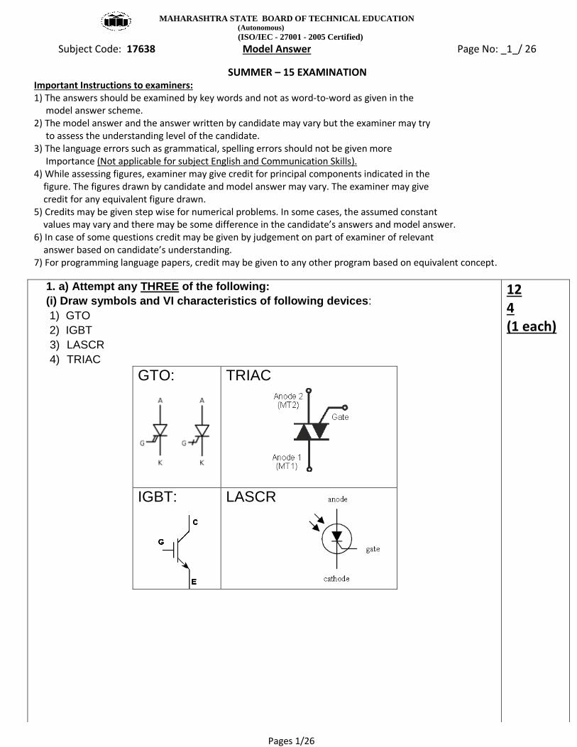
(i) Draw symbols and VI characteristics of following devices:
1) GTO
2) IGBT
3) LASCR
4) TRIAC
GTO:
TRIAC
IGBT: LASCR
12 4 (1 each)

MAHARASHTRA STATE BOARD OF TECHNICAL EDUCATION (Autonomous)
(ISO/IEC - 27001 - 2005 Certified)
Subject Code: 17638 Model Answer Page No: _2_/ 26
SUMMER – 15 EXAMINATION
Pages 2/26
(ii) Following figure shows circuit diagram of a six-pulse converter.
With supply phase sequence A-B-C, indicate the firing
sequence of six thyristors. (Refer Fig. No. 1)
Firing Sequence is as follows: T1–T6, T2-T6, T2-T4, T3-T4, T3-T5, T1-T5
4
iii) Draw circuit diagram of single phase full bridge inverter. Draw waveforms of load
voltage and load current for RL load.
2+2

MAHARASHTRA STATE BOARD OF TECHNICAL EDUCATION (Autonomous)
(ISO/IEC - 27001 - 2005 Certified)
Subject Code: 17638 Model Answer Page No: _3_/ 26
SUMMER – 15 EXAMINATION
Pages 3/26
(iv) Explain the technique for speed control of DC series motor using thyristor
converter.
The basic equations of dc series motor are:
1
22
'
'
2 22
2 2
( )
( ' )
a
a
a
T f a a b
Tb a a
a f
T T
a f
T K I
K I
T K I
V R R I E
VE K K I I
R R K
K V VT T
R R K
The above equation indicates that for constant armature voltage the speed and
torque are inversely related and speed of dc series motor is inversely proportional to
flux. As the field winding is in series with the armature, field current and armature
current are same. At small armature current, flux is small and speed of the motor is
higher. In loaded conditions, speed is decreased.
From the torque speed characteristics, torque and speed are inversely proportional.
It is also seen that, for fixed load torque, by control of armature voltage, the speed
can be controlled. Armature voltage is controlled by controlling firing angle of a
thyristor converter.
4 2+2

MAHARASHTRA STATE BOARD OF TECHNICAL EDUCATION (Autonomous)
(ISO/IEC - 27001 - 2005 Certified)
Subject Code: 17638 Model Answer Page No: _4_/ 26
SUMMER – 15 EXAMINATION
Pages 4/26
Q1. b) Attempt any ONE of the following
(i) Draw waveforms of the following power electronic circuit for gate pulses pattern as shown in Figure No. 2. Indicate load voltage, current, capacitor voltage.
6 2 each

MAHARASHTRA STATE BOARD OF TECHNICAL EDUCATION (Autonomous)
(ISO/IEC - 27001 - 2005 Certified)
Subject Code: 17638 Model Answer Page No: _5_/ 26
SUMMER – 15 EXAMINATION
Pages 5/26
(ii) Draw circuit diagram of single phase mid-point converter. Draw output
voltage, current waveforms with R-L load.
6 2+4

MAHARASHTRA STATE BOARD OF TECHNICAL EDUCATION (Autonomous)
(ISO/IEC - 27001 - 2005 Certified)
Subject Code: 17638 Model Answer Page No: _6_/ 26
SUMMER – 15 EXAMINATION
Pages 6/26
Q2 Attempt any FOUR of the following:
a) State any four voltage and current rating of thyristor.
Different voltage ratings of a thyristor are
1) Peak Working Forward Blocking or Forward OFF State Voltage (VDWM)
2) Peak Repetitive Forward Blocking Voltage (VDRM)
3) Peak Non-Repetitive or Surge Forward Blocking Voltage (VDSM)
4) Peak Working Revere Voltage (VRWM)
5) dv/dt rating
6) Forward breakover voltage (Vbo)
Different current ratings are
1) Maximum RMS Current Rating (IRMS)
2) Maximum Average Current Rating (IAV)
3) Maximum Surge Current (ISM)
4) di/dt Rating of SCR
5) Holding current
6) Latching current
b) Draw circuit diagram and waveforms of single phase cycloconverter.
I
16 4 2+2 4 2+2

MAHARASHTRA STATE BOARD OF TECHNICAL EDUCATION (Autonomous)
(ISO/IEC - 27001 - 2005 Certified)
Subject Code: 17638 Model Answer Page No: _7_/ 26
SUMMER – 15 EXAMINATION
Pages 7/26
c) Indicate firing angle and conduction angle.for half wave controlled converter
connected to
R Load
R-L load
d) Explain turn-OFF methods of a thyristor. (credit also may be given if turn off process is explained)
There are six different methods to turn off thyristor.
Forced commutation
Class A- Series resonant turn off
Class B- Parallel resonant trurn off
Class C –Charged capacitor switched by a load carrying SCR (complementary commutation)
Class D-Charged capacitor switched by an auxiliary SCR
Class E- External Pulse commutation
Natural Commutation:
Class F- Thyristor turned off by reversal of AC line polarity
4 2+2 4
Conduction angle R Load
Conduction angle RL Load
Firing angle

MAHARASHTRA STATE BOARD OF TECHNICAL EDUCATION (Autonomous)
(ISO/IEC - 27001 - 2005 Certified)
Subject Code: 17638 Model Answer Page No: _8_/ 26
SUMMER – 15 EXAMINATION
Pages 8/26
e) Describe how control of firing angle can control speed of DC shunt motor controlled
by thyristor converter.
The above equation indicates that control of armature voltage controls speed of dc motor. By
using thyristor converter, armature voltage is controlled. Control of firing angle controls
average armature voltage
Consider the case of full wave controlled bridge converter. The average output voltage is
given by
2cosm
oavg
EV
The average output voltage is controlled by control of
Control of firing angle controls average output voltage of converter i.e. terminal voltage of dc
motor. Increase in terminal voltage increases speed of motor as seen from above equation
4 2+2

MAHARASHTRA STATE BOARD OF TECHNICAL EDUCATION (Autonomous)
(ISO/IEC - 27001 - 2005 Certified)
Subject Code: 17638 Model Answer Page No: _9_/ 26
SUMMER – 15 EXAMINATION
Pages 9/26
f) Classify choppers based on quadrants.
Classification of choppers based on quadrants
4

MAHARASHTRA STATE BOARD OF TECHNICAL EDUCATION (Autonomous)
(ISO/IEC - 27001 - 2005 Certified)
Subject Code: 17638 Model Answer Page No: _10_/ 26
SUMMER – 15 EXAMINATION
Pages 10/26
Q3 Attempt any FOUR of the following
a) Draw two transistor equivalent circuit of a thyristor and explain turn-ON process.
Positive Gate bias turns ON Q2, This allows IC2 to flow IC2 = IB2 If the anode is positive
(i.e emitter of Q1), PN junction of Q1 will be forward biased and Q1 turns ON .This allows
IC1 to flow which adds to base current IB2. This regenerative action continues till Q1 and
Q2 are driven to saturation. Now Removal of gate bias does not affect ON State of Q1
and Q2
When gate current IG is positive, 1 2 approaches unity and anode is driven to
saturation and thyristor behaves as a closed switch.
b) What is effect of connecting freewheeling diode on controlled converter
performance?(any two)
1) Freewheeling diode prevents negative load voltage.
2) It reduces reactive power flow.
3) It improves power factor of input.
4) Improves load performance.
c) Draw equivalent circuit of thyristor mounted on heat sink. Indicate thermal
resistances.
16 4 2+2 2+2 2+2
2 1
2 1 2
1 2
From the equivalent circuit,
we see that
1
C B
g CBO CBO
A
I I
I I II

MAHARASHTRA STATE BOARD OF TECHNICAL EDUCATION (Autonomous)
(ISO/IEC - 27001 - 2005 Certified)
Subject Code: 17638 Model Answer Page No: _11_/ 26
SUMMER – 15 EXAMINATION
Pages 11/26
d) Draw schematic circuit diagram of Class-B chopper and necessary waveforms.
e) Draw schematic circuit diagram of thyristorized battery charger.
4 2+2 4

MAHARASHTRA STATE BOARD OF TECHNICAL EDUCATION (Autonomous)
(ISO/IEC - 27001 - 2005 Certified)
Subject Code: 17638 Model Answer Page No: _12_/ 26
SUMMER – 15 EXAMINATION
Pages 12/26
Q4. Attempt any THREE of the following:
i) Describe control techniques for control of chopper.
A chopper is high speed semiconductor switch. It connects source to load and disconnects
the load from load at a fast speed.
The average value of the output voltage V0 can be controlled by controlling duty ratio. The
chopper control techniques or the strategies of duty ratio control are as follows:
1) Constant Frequency system
In this scheme, the on-time Ton is varied but chopping frequency f is kept constant.
2) Variable frequency system
In this scheme, the chopping frequency f is controlled and either ON time or OFF time
is kept constant.
12 4 2+2

MAHARASHTRA STATE BOARD OF TECHNICAL EDUCATION (Autonomous)
(ISO/IEC - 27001 - 2005 Certified)
Subject Code: 17638 Model Answer Page No: _13_/ 26
SUMMER – 15 EXAMINATION
Pages 13/26
ii) Draw circuit diagram of UJT triggering of SCR and draw waveforms to show
firing angle control.
iii) Describe use of thyristor in static VAR compensation.
In static VAr compensation, Reactive power demanded by load is supplied locally by the VAr
compensator. Two important thyristor based VAr compensators are
1) Thyristor controlled reactor (TCR)
2) Thyristor switched capacitor (TSC)
Thyristor controlled reactor consists of a thyristor switch connected in series with linear
inductor. Current in inductor is varied by controlling firing angle.
4 2+2 4 (2+2)

MAHARASHTRA STATE BOARD OF TECHNICAL EDUCATION (Autonomous)
(ISO/IEC - 27001 - 2005 Certified)
Subject Code: 17638 Model Answer Page No: _14_/ 26
SUMMER – 15 EXAMINATION
Pages 14/26
Thyristor switched capacitor (TSC) consists of a power capacitor connected in series with a
bidirectional thyristor valve and, usually, a current limiting reactor (inductor).
iv) Draw circuit diagram of JONES chopper. Draw waveforms of Toad voltage and
capacitor voltage.
4 2+2

MAHARASHTRA STATE BOARD OF TECHNICAL EDUCATION (Autonomous)
(ISO/IEC - 27001 - 2005 Certified)
Subject Code: 17638 Model Answer Page No: _15_/ 26
SUMMER – 15 EXAMINATION
Pages 15/26
b) Attempt any ONE of the following:
(i) What is meaning of “Harmonics”? Draw circuit diagram of any one type of
harmonic filter used at inverter output.
Harmonics are sinusoidal voltages or currents having frequencies that are integer multiples of the frequency at which the supply system is designed to operate. Harmonics arise due to non-sinusoidal/chopped nature of the waveform at output of power electronic equipment. Different types of harmonic filters used at inverter output are shown below.
6 6 3+3
(ii) Describe speed control of 3pH. Induction motor using Voltage Source Inverter.
What is the need of controlling v/f ratio?
Speed of induction motor is given by 120
s
fN
P
By changing frequency, speed can be controlled. Apart from frequency, the applied
voltage needs to be controlled, to keep the air gap flux constant and avoid saturation. In
order to control speed, frequency and applied voltage are to be simultaneously controlled,
Following block diagram shows v/f control scheme
The dc voltage is obtained from a phase controlled rectifier. This dc voltage is fed to a
6 3+3

MAHARASHTRA STATE BOARD OF TECHNICAL EDUCATION (Autonomous)
(ISO/IEC - 27001 - 2005 Certified)
Subject Code: 17638 Model Answer Page No: _16_/ 26
SUMMER – 15 EXAMINATION
Pages 16/26
force commutated bridge inverter which generates the required variable voltage variable
frequency output connected to the delta connected stator of 3ph induction motor. The
output of the inverter is stepped square wave. The phase controlled converter and
inverter are interconnected by a link inductor which smoothens the dc voltage ripples. The
closed loop control adjusts the firing angle of the converter to maintain the required dc
voltage at the input of the voltage source inverter and adjusts the firing of thyristors of the
inverter to maintain the required frequency.
Q5. Attempt any FOUR of the following:
a) Describe effect of supply inductance on output voltage of converter.
The effect of source inductance is delay in commutation of thyristors , as it takes a
finite time for the current to decay to zero in the outgoing thyristor, while the current will
rise at the same rate in the incoming thyristor. The commutation process may occupy a
quite significant period of time, during which both the "incoming" and "outgoing" thyristors
arc simultaneous in conduction. This period, during which both the outgoing and incoming
thyristors are conducting, is known as the overlap period. The output average voltage is
dropped due to loss of output voltage during commutation angle
16 4 2+2

MAHARASHTRA STATE BOARD OF TECHNICAL EDUCATION (Autonomous)
(ISO/IEC - 27001 - 2005 Certified)
Subject Code: 17638 Model Answer Page No: _17_/ 26
SUMMER – 15 EXAMINATION
Pages 17/26
(b) Describe working principle of dielectric heating using thyristor.
If an ac voltage is applied across a piece of insulator, an electric current flows. The current
has two components, capacitive and resistive current. There is a power loss because of the
resistive component. The power loss called as dielectric loss gets converted into heat and
increases temperature of the insulating piece.
4 (2+2)

MAHARASHTRA STATE BOARD OF TECHNICAL EDUCATION (Autonomous)
(ISO/IEC - 27001 - 2005 Certified)
Subject Code: 17638 Model Answer Page No: _18_/ 26
SUMMER – 15 EXAMINATION
Pages 18/26
(c) Describe working of basic Current Source Inverter (CSI) based induction
motor control.
Current-source inverters requires a "stiff" constant current source input - thus are
sometimes referred to as CSI (current source inverters or current stiff inverters).
A large inductance can be used to change a variable voltage input to a variable current
input.
VSI-inverters and CSI-inverters are dual to each other.
The constant dc current ld is switched through the thyristors to create a 3phase 6-step
symmetrical line current waves.
The current is switched sequentially into one of the motor phases by the top half of the
inverter and returns to the dc link from another of the phases via the bottom half of the
inverter.
By switching every 2π/3 radians, a 6-step current waveform can be applied to the
motor.
4 2+2
MAHARASHTRA STATE BOARD OF TECHNICAL EDUCATION (Autonomous)
(ISO/IEC - 27001 - 2005 Certified)
Subject Code: 17638 Model Answer Page No: _19_/ 26
SUMMER – 15 EXAMINATION
Pages 19/26
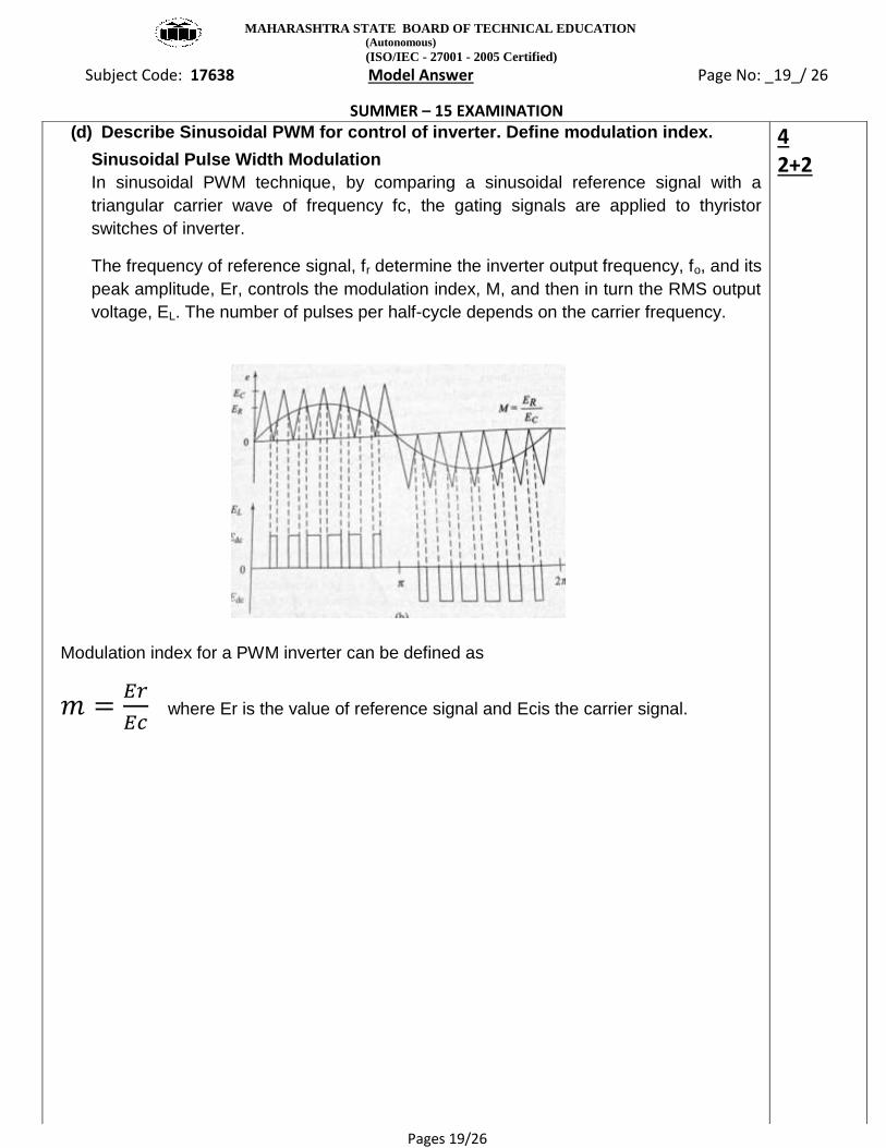
(d) Describe Sinusoidal PWM for control of inverter. Define modulation index.
Sinusoidal Pulse Width Modulation
In sinusoidal PWM technique, by comparing a sinusoidal reference signal with a
triangular carrier wave of frequency fc, the gating signals are applied to thyristor
switches of inverter.
The frequency of reference signal, fr determine the inverter output frequency, fo, and its
peak amplitude, Er, controls the modulation index, M, and then in turn the RMS output
voltage, EL. The number of pulses per half-cycle depends on the carrier frequency.
Modulation index for a PWM inverter can be defined as
where Er is the value of reference signal and Ecis the carrier signal.
4 2+2

MAHARASHTRA STATE BOARD OF TECHNICAL EDUCATION (Autonomous)
(ISO/IEC - 27001 - 2005 Certified)
Subject Code: 17638 Model Answer Page No: _20_/ 26
SUMMER – 15 EXAMINATION
Pages 20/26
(e) Describe electric welding using thyristor
The welding machine receives ac power, by means of a timing device, through a power
transformer, a circuit breaker, and an SCR. Inside the welding machine, a welding
transformer reduces the voltage at the electrode tips (1 to 10 V) and supply a large
welding current, while drawing about 50 to 2000 A from the ac supply.
The resistance between the metal pieces decreases when they are forced together by
the electrodes with greater pressure. To make a weld, current needs to flow for only a
fraction of a second. The SCR controlled circuits are used which must close and open
the circuit quickly, and it does this hundreds of times each hour. The timings of the
welding process which may be divided into squeeze time, weld time, hold time, and OFF
time, are controlled by a sequence timer.
4 2+2

MAHARASHTRA STATE BOARD OF TECHNICAL EDUCATION (Autonomous)
(ISO/IEC - 27001 - 2005 Certified)
Subject Code: 17638 Model Answer Page No: _21_/ 26
SUMMER – 15 EXAMINATION
Pages 21/26
(f) Identify the mistakes in the circuit shown in Figure No. 3 and correct the same
and draw voltage output and current waveforms for R-L Load.
The mistake in the given circuit: diodes D1 and D2 are connected such that it will cause
short circuit across supply. The direction of D1 and D2 must be reversed to correct the
diagram.
The circuit shown in the diagram is of half bridge inverter.
4 2+2

MAHARASHTRA STATE BOARD OF TECHNICAL EDUCATION (Autonomous)
(ISO/IEC - 27001 - 2005 Certified)
Subject Code: 17638 Model Answer Page No: _22_/ 26
SUMMER – 15 EXAMINATION
Pages 22/26
Q6. Attempt any FOUR of the following
(a) Draw waveforms to indicate turn-ON process of a thyristor. Indicate rise time,
delay and spread time.
16 4

MAHARASHTRA STATE BOARD OF TECHNICAL EDUCATION (Autonomous)
(ISO/IEC - 27001 - 2005 Certified)
Subject Code: 17638 Model Answer Page No: _23_/ 26
SUMMER – 15 EXAMINATION
Pages 23/26
(b) Describe thyristorised induction heating.
Induction heating operates on the principle of induction in order to heat an electrically
conducting material. The material to be heated is known as the work piece and the coil
around it as work coil. The coil acts as primary and work piece acts as short circuited
secondary. When primary is excited by high frequency ac supply, eddy currents will
set up in the work piece and power loss will heat up the object.
4 2+2

MAHARASHTRA STATE BOARD OF TECHNICAL EDUCATION (Autonomous)
(ISO/IEC - 27001 - 2005 Certified)
Subject Code: 17638 Model Answer Page No: _24_/ 26
SUMMER – 15 EXAMINATION
Pages 24/26
(c) State differences between MOSFET and thyristor inverter.
Power MOSFET based inverter Thyristor based inverter
These are based on Power MOSFETS
as switching devices
These are based on SCR as switching
devices
Power MOSFETs are voltage
controlled devices. trigger circuit
operates at small power
SCRs are current controlled devices
and triggering circuit consumes more
power
Fast trun ON and OFF Slow Turn ON and OFF as compared to
MOSFET
Inverters operate and higher
switching frequency
Inverters operate at lower switching
frequency
Switching losses are less Switching losses are more
Operate at smaller power rating Can operate higher power rating
Quality of the inverter output
waveform can be improved by
increasing switching frequency
Quality of the output waveform is less
4 1 each
MAHARASHTRA STATE BOARD OF TECHNICAL EDUCATION (Autonomous)
(ISO/IEC - 27001 - 2005 Certified)
Subject Code: 17638 Model Answer Page No: _25_/ 26
SUMMER – 15 EXAMINATION
Pages 25/26
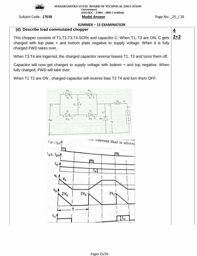
(d) Describe load commutated chopper
This chopper consists of T1,T2,T3,T4 SCRs and capacitor C. When T1, T2 are ON, C gets
charged with top plate + and bottom plate negative to supply voltage. When it is fully
charged FWD takes over.
When T3,T4 are trigerred, the charged capacitor reverse biases T1, T2 and turns them off.
Capacitor will now get charged to supply voltage with bottom + and top negative. When
fully charged, FWD will take over.
When T1 T2 are ON , charged capacitor will reverse bias T3 T4 and turn them OFF.
4 2+2

MAHARASHTRA STATE BOARD OF TECHNICAL EDUCATION (Autonomous)
(ISO/IEC - 27001 - 2005 Certified)
Subject Code: 17638 Model Answer Page No: _26_/ 26
SUMMER – 15 EXAMINATION
Pages 26/26
(e) Describe street light control using thyristor.
In street light control, the thyristorised controllers are employed as light dimmers. By
controlling AC voltage applied to illumination load, the intensity of the street light is
controlled. AC voltage is controlled as function of time of the day or intensity of ambient
light. During day time, load is disconnected from supply. In the evening time, voltage is
gradually increased reducing the firing angle.
4 2+2