summary of multiagent planning architecturewilkins/papers/mpa-manual-short.pdf · summary of...
TRANSCRIPT
Working Document:Revisions as of October 9, 1998
Summary ofMultiagent Planning ArchitectureMPA Version 1.7
SRI Project 7150Contract No. F30602-95-C-0235
By: David E. Wilkins, Senior Computer ScientistKaren L. Myers, Senior Computer ScientistMarie desJardins, Computer ScientistPauline M. Berry, Computer ScientistSRI International
Contents
1 Introduction 1
2 The Multiagent Planning Architecture 2
2.1 Planning Cells . . . . . . . . . . . . . . . . . . . . . . . . . . . . . . . . . . 3
2.2 Common Plan Representation . . . . . . . . . . . . . . . . . . . . . . . . . 5
2.2.1 Plan Model . . . . . . . . . . . . . . . . . . . . . . . . . . . . . . . 6
2.2.2 ASCII Acts . . . . . . . . . . . . . . . . . . . . . . . . . . . . . . . 7
3 MPA Infrastructure 7
3.1 Agent Construction and Wrappers . . . . . . . . . . . . . . . . . . . . . . . 7
3.2 How Will Agents Communicate? . . . . . . . . . . . . . . . . . . . . . . . . 8
3.3 MPA Messages . . . . . . . . . . . . . . . . . . . . . . . . . . . . . . . . . 9
4 Plan Servers 10
4.1 Communication and Plan Performatives . . . . . . . . . . . . . . . . . . . . 11
4.2 Annotations . . . . . . . . . . . . . . . . . . . . . . . . . . . . . . . . . . . 11
4.3 Triggers . . . . . . . . . . . . . . . . . . . . . . . . . . . . . . . . . . . . . 13
4.4 Queries . . . . . . . . . . . . . . . . . . . . . . . . . . . . . . . . . . . . . 14
4.5 Act Plan Server . . . . . . . . . . . . . . . . . . . . . . . . . . . . . . . . . 15
5 Planning-Cell Managers 16
5.1 Meta Planning-Cell Manager . . . . . . . . . . . . . . . . . . . . . . . . . . 17
5.2 Overview of the PCM . . . . . . . . . . . . . . . . . . . . . . . . . . . . . . 19
5.3 Planning Cell Characteristics . . . . . . . . . . . . . . . . . . . . . . . . . . 20
5.4 PCM Invocation . . . . . . . . . . . . . . . . . . . . . . . . . . . . . . . . . 21
6 Integrating Planning, Scheduling and Execution 22
6.1 Continuous Planning and Execution . . . . . . . . . . . . . . . . . . . . . . 22
6.1.1 Executor Agent . . . . . . . . . . . . . . . . . . . . . . . . . . . . . 23
6.2 Planning and Scheduling . . . . . . . . . . . . . . . . . . . . . . . . . . . . 24
6.2.1 Planner Agents: Search Manager and Critic Manager . . . . . . . . . 24
6.2.2 Scheduler Agent . . . . . . . . . . . . . . . . . . . . . . . . . . . . 26
i
7 Single Planning Cell Configuration 27
7.1 Control of the Planning Process . . . . . . . . . . . . . . . . . . . . . . . . 29
7.2 Demonstration Scenario . . . . . . . . . . . . . . . . . . . . . . . . . . . . . 29
8 Multiple Planning Cell Demonstrations 30
8.1 June 1997 Demonstration . . . . . . . . . . . . . . . . . . . . . . . . . . . . 30
8.2 TIE 97-1 Demonstration . . . . . . . . . . . . . . . . . . . . . . . . . . . . 32
8.2.1 ACP Knowledge Base . . . . . . . . . . . . . . . . . . . . . . . . . 32
8.2.2 Demonstration Flow . . . . . . . . . . . . . . . . . . . . . . . . . . 33
9 Future Work 34
10 Summary 34
ii

1 Introduction
The Multiagent Planning Architecture (MPA) is a framework for integrating diverse technolo-
gies into a system capable of solving complex planning problems. MPA has been designed
for application to planning problems that cannot be solved by individual systems, but rather
require the coordinated efforts of a diverse set of technologies and human experts. Software
agents within MPA are expected to be sophisticated problem-solving systems in their own
right, and may span a range of programming languages. MPA’s open design facilitates rapid
incorporation of tools and capabilities, which in turn encourages experimentation with new
technologies.
MPA provides protocols to support the sharing of knowledge and capabilities among
agents involved in cooperative planning and problem solving. MPA allows planning systems
to capitalize on the benefits of distributed computing architectures for efficiency and robust-
ness. For example, MPA is capable of generating multiple, alternative plans in parallel.
Agents within MPA share well-defined, uniform interface specifications, so that we can
explore ways of reconfiguring, reimplementing, and adding new capabilities to the planning
system. This paper describes at least two areas in which such exploration was undertaken. The
first is exploring alternative strategies for integrating planning and scheduling. We decom-
pose a DARPA/Rome Laboratory Planning Initiative (ARPI) planning system and an ARPI
scheduling system into component modules, where each component becomes its own plan-
ning agent (PA). This decomposition allows these ARPI technologies to be more tightly and
flexibly integrated.
A second area of exploration is the definition of organizational units for agents that permit
flexible control policies in generating plans. Within MPA, notions ofbaselevel planning cells
andmetalevel planning cellshave been defined, where the baselevel cells provide sequential
solution generation and the metalevel cells employ baselevel cells to support parallel genera-
tion of qualitatively different solutions. Metalevel cells provide the ability to rapidly explore
the space of solutions to a given planning problem. Meta-PAs (PAs that control other PAs) de-
fine different control strategies among the PAs under their control. For example, one meta-PA
might tightly couple planning and scheduling while another might loosely couple them. At a
higher level, meta-PAs might use different algorithms to accept a stream of planning requests
and distribute them to PAs that are not already busy.
The MPA framework has been used to develop several large-scale problem-solving sys-
tems for the domain of Air Campaign Planning (ACP), which was first used in ARPI’s IFD-4
1

(Fourth Integrated Feasibility Demonstration). MPA was used as the infrastructure for ARPI’s
Technology Integration Experiment (TIE) 97-1, providing plan generation and evaluation ca-
pabilities. This application integrated a set of technologies that spanned plan generation,
scheduling, temporal reasoning, simulation, and visualization. These technologies cooper-
ated in the development and evaluation of a complex plan containing over 4000 nodes. This
integration has validated the utility of MPA for combining sophisticated stand-alone systems
into a powerful integrated problem-solving framework.
This paper is a working document that describes MPA from the point of view of someone
wishing to create an MPA agent. This project’s home page can be found at
http://www.ai.sri.com/˜wilkins/mpa
2 The Multiagent Planning Architecture
MPA is organized around the concept of aplanning cell, which consists of a collection of
agents committed to a particular planning process. A planning cell contains two distinguished
agents — theplanning-cell managerand theplan server. Theplanning-cell managercom-
poses a planning cell drawn from a community of agents and distributes the planning task
among the selected agents. Theplan serveris the central repository for plans and plan-related
information during the course of a planning task. It accepts incoming information from PAs,
performs necessary processing, stores relevant information, and makes this information ac-
cessible to any PA through queries. An optionalknowledge serverstores application-specific
information of relevance to the planning process, which may be shared among all cell agents.
The knowledge server might store, for example, situation models, an object hierarchy, legacy
databases, and the set of action descriptions to be used in planning.
MPA also supports the use of multiple planning cells to simultaneously produce alternative
plans. Multiple planning cells are controlled by ameta planning-cell manager, which accepts
a stream of asynchronous planning requests and distributes them to available planning cells.
A meta planning-cell manager implemented in MPA is described in Section 5.1.
Supporting the MPA architecture requires a significant amount of infrastructure. One com-
ponent is ashared plan representationthat can be understood by all planning agents. MPA
employs the Act formalism for this purpose, as described in Section 2.2. Additional compo-
nents include a communication substrate to support multithreaded interagent message passing
across networks, and tools to facilitate the construction of agents and planning cells. MPA
2

provides both a message format and a message-handling protocol to support the sharing of
knowledge among agents involved in cooperative plan generation. With MPA messages, soft-
ware modules written in different programming languages can easily communicate. We have
demonstrated agents written in C, C++, LISP, and Java communicating with each other.
In this section, we describe planning cells and the common plan representation. MPA
intends to have PAs communicate using the common plan representation and the agent com-
munication languages being developed by other ARPI projects, but other alternatives are being
explored as well. Agent-construction tools and communication capabilities are described in
Section 3, plan servers are described in Section 4, and planning-cell managers are described
in Section 5.
We have reviewed emerging standards for distributed architectures and attempted to be
consistent when possible with other agent frameworks, particularly the ARPA efforts in I3
and AITS (formerly JTF-ATD). To better understand the capabilities our architecture ought
to support and to help make MPA as useful as possible to the broader ARPI community, we
surveyed the software tools and products that are available or under development by ARPI
researchers. The results of this survey will identify technologies that are sufficiently far along
in their development to be considered for inclusion as PAs.
2.1 Planning Cells
MPA planning cells are hierarchically organized collections of planning agents that are com-
mitted to one particular planning process for a given period of time (see Figure 1). Each
planning cell has a meta-PA that serves as the planning-cell manager (or, simply thecell man-
ager), which decomposes a planning task and distributes it to the PAs of the planning cell.
Cell managers hierarchically decompose a planning task and distribute it to the PAs and
meta-PAs of a planning cell, as shown in Figure 1. The planning cell is the closure of all
PAs (and meta-PAs) registered by the cell manager and any PAs they invoke. Individual cell
managers compose their planning cells to reflect their own planning approach. For example,
a mixed-initiative meta-PA may include human agents in its cell. One cell manager might
loosely couple planning and scheduling, while another might tightly couple them.
The cell manager maintains a Planning-Cell Designator (PCD) that defines a set ofrolesto
be filled. A role constitutes a capacity or responsibility, such as plan generation or scheduling.
Each role must be filled by an agent with the capabilities required by that role. The PCD
3
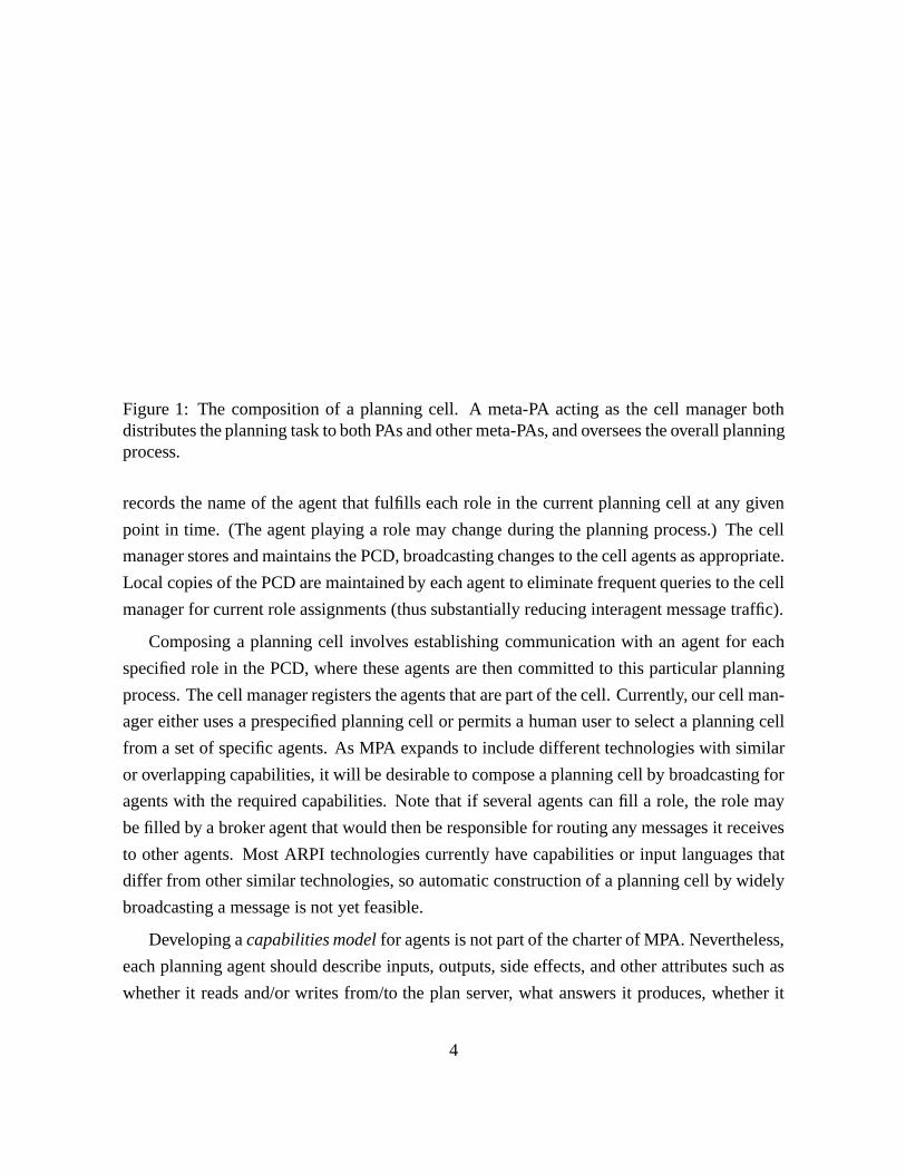
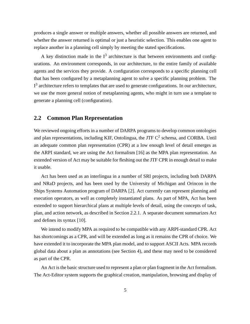
Figure 1: The composition of a planning cell. A meta-PA acting as the cell manager bothdistributes the planning task to both PAs and other meta-PAs, and oversees the overall planningprocess.
records the name of the agent that fulfills each role in the current planning cell at any given
point in time. (The agent playing a role may change during the planning process.) The cell
manager stores and maintains the PCD, broadcasting changes to the cell agents as appropriate.
Local copies of the PCD are maintained by each agent to eliminate frequent queries to the cell
manager for current role assignments (thus substantially reducing interagent message traffic).
Composing a planning cell involves establishing communication with an agent for each
specified role in the PCD, where these agents are then committed to this particular planning
process. The cell manager registers the agents that are part of the cell. Currently, our cell man-
ager either uses a prespecified planning cell or permits a human user to select a planning cell
from a set of specific agents. As MPA expands to include different technologies with similar
or overlapping capabilities, it will be desirable to compose a planning cell by broadcasting for
agents with the required capabilities. Note that if several agents can fill a role, the role may
be filled by a broker agent that would then be responsible for routing any messages it receives
to other agents. Most ARPI technologies currently have capabilities or input languages that
differ from other similar technologies, so automatic construction of a planning cell by widely
broadcasting a message is not yet feasible.
Developing acapabilities modelfor agents is not part of the charter of MPA. Nevertheless,
each planning agent should describe inputs, outputs, side effects, and other attributes such as
whether it reads and/or writes from/to the plan server, what answers it produces, whether it
4
produces a single answer or multiple answers, whether all possible answers are returned, and
whether the answer returned is optimal or just a heuristic selection. This enables one agent to
replace another in a planning cell simply by meeting the stated specifications.
A key distinction made in the I3 architecture is that between environments and config-
urations. An environment corresponds, in our architecture, to the entire family of available
agents and the services they provide. A configuration corresponds to a specific planning cell
that has been configured by a metaplanning agent to solve a specific planning problem. The
I3 architecture refers to templates that are used to generate configurations. In our architecture,
we use the more general notion of metaplanning agents, who might in turn use a template to
generate a planning cell (configuration).
2.2 Common Plan Representation
We reviewed ongoing efforts in a number of DARPA programs to develop common ontologies
and plan representations, including KIF, Ontolingua, the JTF C2 schema, and CORBA. Until
an adequate common plan representation (CPR) at a low enough level of detail emerges as
the ARPI standard, we are using the Act formalism [16] as the MPA plan representation. An
extended version of Act may be suitable for fleshing out the JTF CPR in enough detail to make
it usable.
Act has been used as an interlingua in a number of SRI projects, including both DARPA
and NRaD projects, and has been used by the University of Michigan and Orincon in the
Ships Systems Automation program of DARPA [2]. Act currently can represent planning and
execution operators, as well as completely instantiated plans. As part of MPA, Act has been
extended to support hierarchical plans at multiple levels of detail, using the concepts of task,
plan, and action network, as described in Section 2.2.1. A separate document summarizes Act
and defines its syntax [10].
We intend to modify MPA as required to be compatible with any ARPI-standard CPR. Act
has shortcomings as a CPR, and will be extended as long as it remains the CPR of choice. We
have extended it to incorporate the MPA plan model, and to support ASCII Acts. MPA records
global data about a plan as annotations (see Section 4), and these may need to be considered
as part of the CPR.
An Act is the basic structure used to represent a plan or plan fragment in the Act formalism.
The Act-Editor system supports the graphical creation, manipulation, browsing and display of
5
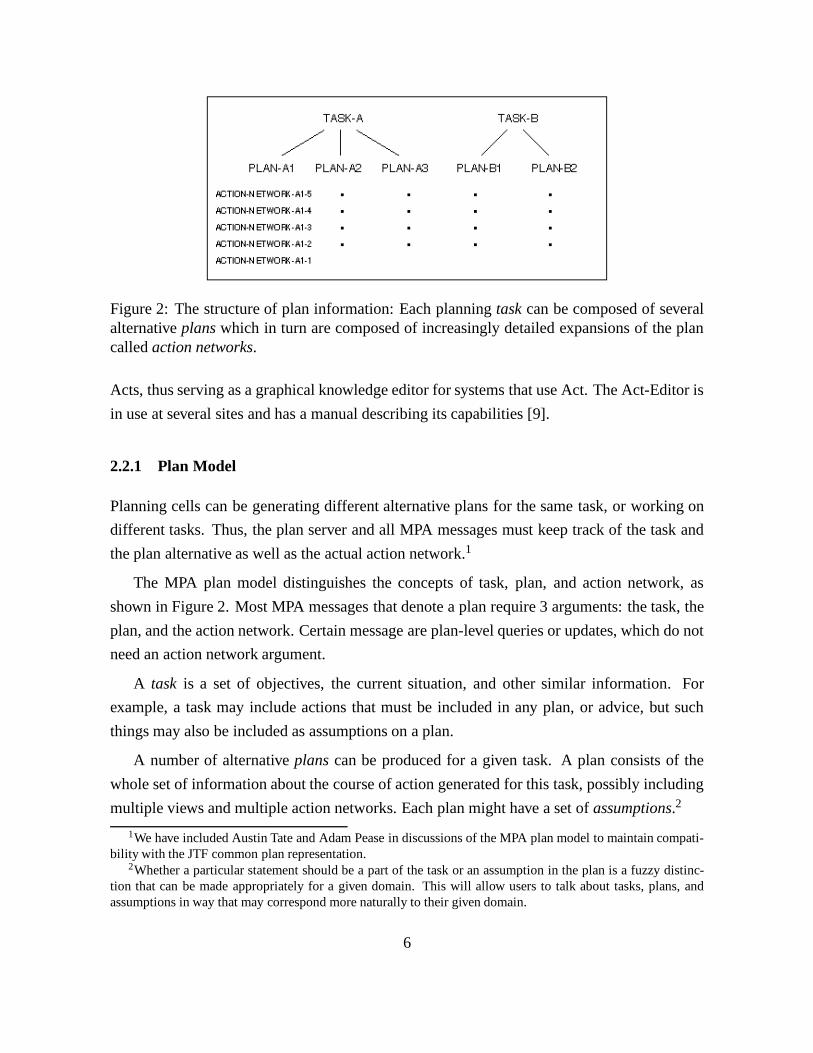
Figure 2: The structure of plan information: Each planningtaskcan be composed of severalalternativeplanswhich in turn are composed of increasingly detailed expansions of the plancalledaction networks.
Acts, thus serving as a graphical knowledge editor for systems that use Act. The Act-Editor is
in use at several sites and has a manual describing its capabilities [9].
2.2.1 Plan Model
Planning cells can be generating different alternative plans for the same task, or working on
different tasks. Thus, the plan server and all MPA messages must keep track of the task and
the plan alternative as well as the actual action network.1
The MPA plan model distinguishes the concepts of task, plan, and action network, as
shown in Figure 2. Most MPA messages that denote a plan require 3 arguments: the task, the
plan, and the action network. Certain message are plan-level queries or updates, which do not
need an action network argument.
A task is a set of objectives, the current situation, and other similar information. For
example, a task may include actions that must be included in any plan, or advice, but such
things may also be included as assumptions on a plan.
A number of alternativeplanscan be produced for a given task. A plan consists of the
whole set of information about the course of action generated for this task, possibly including
multiple views and multiple action networks. Each plan might have a set ofassumptions.2
1We have included Austin Tate and Adam Pease in discussions of the MPA plan model to maintain compati-bility with the JTF common plan representation.
2Whether a particular statement should be a part of the task or an assumption in the plan is a fuzzy distinc-tion that can be made appropriately for a given domain. This will allow users to talk about tasks, plans, andassumptions in way that may correspond more naturally to their given domain.
6

An action networkis a description of the plan at some point it its development such that all
agents querying that action network will get the same partial order of goals and actions. We
will refer to the elements of an action network asnodes, where a node can represent an action
or a goal (among other things). Action networks are intermediate results in some planning
process and may be at multiple levels of abstraction.
2.2.2 ASCII Acts
Before MPA, Acts were represented as Grasper-based data structures [6, 10] to support their
display display. Because plans and plan fragments must be easily communicated between
planning agents, we defined a syntax for ASCII specification of Acts, and documented it
in BNF. We have extended the Act-Editor to print Grasper-based Acts and files of Acts in
this ASCII specification, and to read this specification and create Grasper-based Acts, thus
allowing graphical display and manipulation of ASCII Acts.
A separate document summarizes Act, describes functions for manipulating ASCII Acts,
and specifies the current syntax for ASCII Acts [10] (superseding the appendix in our in-depth
description of Act [16]).
3 MPA Infrastructure
An MPA planning cell requires low-level communication capabilities to support asynchronous
agent communication across networks, particularly the Internet. Within MPA, software mod-
ules written in different programming languages can easily communicate. Utilities to facilitate
the construction of agents and planning cells are also required. For example, a capabilities
model will aid in planning cell construction.
In this section, we describe wrappers and agent libraries developed by SRI to facilitate the
construction of agents and planning cells, and MPA’s low-level communication capabilities.
3.1 Agent Construction and Wrappers
MPA provides wrappers and agent libraries that support interagent message passing, multi-
threaded processing, tracing of messages on the screen, and logging of messages in a history.
To allow more complex responses to incoming requests, such as interrupting certain responses
7
to reprioritize the computation, it is possible to combine SRI’s PRS (Procedural Reasoning
System) [17] with the MPA LISP wrapper. PRS is the basis for both our cell manager, plan
server, and meta planning-cell manager. PRS is not a required part of any agent, and agent
interface specifications are independent of PRS.
MPA agents have been implemented in C, C++, LISP, and Java. MPA provides an exten-
sive wrapper for LISP, and some support for C, as described below.
MPA provides an agent wrapper in LISP that supports asynchronous interagent communi-
cation, including functions for making, sending and replying to messages that log and trace
the message exchange. There are also functions for starting and killing agents, and for starting
and stopping tracing. This wrapper can easily be employed by any agent running in LISP.
Other sites have been able to download our wrapper and get an existing LISP program com-
municating as an MPA agent in one day.
MPA provides a library of C functions that can be used to implement a C-language wrapper
for an existing “legacy” agent. This library provides an asynchronous message handler that
invokes the executable image for the legacy agent as requested, and returns the responses. The
handler must be programmed to translate specific messages into suitable invocations of the
legacy agent (e.g., appropriate command line arguments).
MPA makes use of a program named Startit from OAA to initiate, monitor, and terminate
a set of agents. Using Startit greatly facilitates the process of starting and controlling agents.
3.2 How Will Agents Communicate?
Three software packages were considered for providing the low-level communication sub-
strate for invoking procedures over a network:
� Knowledge Query and Manipulation Language (KQML) [4], developed with ARPI sup-port by Loral and the University of Maryland Baltimore County
� Inter-Language Unification (ILU) [5], developed at Xerox-PARC
� Open Agent Architecture (OAA) [7], developed at SRI International
Currently, MPA is demonstrated on top of KQML, until such time as efficiency or robust-
ness considerations force us to consider another approach. A preliminary implementation of
MPA on top of OAA also exists, and an implementation based on ILU is being developed.
8
KQML is not CORBA-compliant, but has good high-level support for declaring agents
and services and facilitating their use. It has been used fairly extensively (both within and
outside of ARPI). The KQML developers stress their set of high-level performatives with
semantics. While we view the semantics of the given performatives as weak, we believe the
use of standard performatives is the best way to proceed. OAA provides more high-level
agent facilitation than does KQML. We found KQML to be easy to use initially, and have
made several extensions to KQML’s LISP interface to improve its robustness and efficiency.
With these fixes, we have found KQML to be fast enough even for low-level messages (where
a tenth of a second is adequate response), and its high-level facilitation to be useful.
3.3 MPA Messages
MPA provides both a message format and a message-handling protocol to support the sharing
of knowledge among agents involved in cooperative problem solving. The message facility
is built on KQML, which provides a set of high-level performatives, calledcommunication
performativesin MPA. MPA further specifies its own set ofplan performatives, which further
specialize messages to MPA. Combinations of communication and plan performatives define
the message protocols and the operations that agents may attempt to invoke by using other
agents, thus providing a substrate on which to build higher-level models of agent interaction.
MPA messages are built using KQML messages, which are lists composed of a performa-
tive followed by a set of fields specified as keyword and value pairs. Of particular importance
is the :content field, which contains the real content of the message, and can be specified in
any agreed upon language.
MPA uses a communication performative to begin a message. The content field of an
MPA message begins with aplan performative, which is a keyword. Plan performatives are
also included in the content of any replies. The general form of the content field of any MPA
message (sending or reply) is
(:plan-performative {value} {keyword-and-value-pairs})
Throughout this document, bracesfg show optional entities. The first value is the plan per-
formative (a keyword), the second (optional) value is an arbitrary value, followed by optional
fields specified as keyword and value pairs. The allowable values, both for the optional value
and the fields, are dependent on the plan performative being used. The one field that may be
9
used for all plan performatives is :error. When there is an error or unexpected condition, the
replying agent adds an :error field to the message, whose value is generally a string explaining
the problem, suitable for passing on to a user.
4 Plan Servers
MPA can be assigned a planning task for which multiple plans may be developed depending on
context, advice or other factors. For each alternative plan being developed, a cell of agents is
committed to the planning process. The question arises of how to maintain and communicate
the current plan state within a planning cell. Our architecture accomplishes this by having a
plan serveragent in each planning cell, although a single plan server agent can be shared by
multiple planning cells. The plan server is apassiveagent in that it responds to messages sent
by other agents. It does not issue performatives to other agents on its own initiative.
The plan server provides the central repository for plan and plan-related information. A
plan model based on the concepts of task, plan, and action network is described in Sec-
tion 2.2.1. The plan server must be able to represent multiple tasks each with multiple al-
ternative plans. This approach is useful when such alternatives share a lot of structure.
The plan server accepts incoming plan information from agents, performs necessary pro-
cessing, and stores relevant information in its internal representation. This information is then
accessible to any cell agent through queries. The plan server maintains all data structures asso-
ciated with the evolving plan. Because a plan server must be able to stand alone, independent
of the control structure or state of any planning agent, the information it contains must in-
clude not only the partially ordered actions of the plan, but also contexts, backtracking points,
declarative information about the state of the plan (e.g., a list of flaws), and so forth.
An MPA plan server is also responsible for storing relevant information about the task,
plan, and the planning process, and notifying various agents of relevant planning events. These
capabilities are implemented byannotationsand triggers, which are each described in their
own sections.
An MPA plan server embodies the notion of differentviewsof a given plan, a powerful
feature of MPA not found in other architectures. A view constitutes some aspect of the plan
that could be relevant to individual MPA agents. For example, the resource usage in a plan
might be one view of the plan. Certain views are directly retrievable from the plan server
10
(e.g., plain-text and graphical representations), while others must be computed by running
algorithms over the basic plan representation (e.g., resource usage).
Views allow the plan server to provide better service to other agents. These agents can get
information in forms they can use instead of having to include their own software to extract
the desired information from the underlying representation (which can be excessively large).
For example, the resource view of the plan might return a representation of the resources used
without needing to return the entire plan structure from which the requesting agent would have
to extract the resources.
Many other plan-server features are desirable, although not strictly necessary for plan gen-
eration. Our research is not concentrating on such features, which include providing persistent
storage, controlling access to the plan or its parts, providing version control for plans, and de-
veloping graphical browsing capabilities.
In general, a large amount of data is static for a given domain, that is, it remains the same
for each alternative plan. This information need not be stored in each plan server used in this
domain. Instead, a knowledge server will handle requests for static knowledge (perhaps a plan
server forwards such requests).
4.1 Communication and Plan Performatives
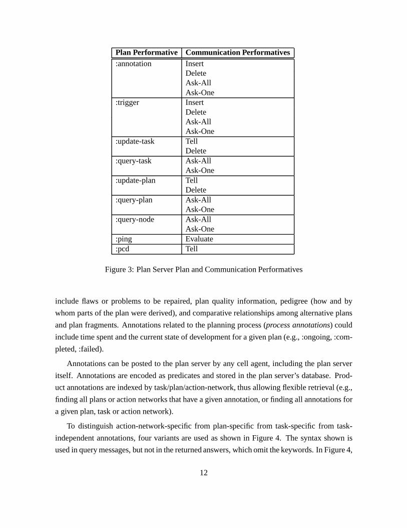
The currently allowed combinations of communication and plan performatives in messages
handled by an MPA plan server are shown in Figure 3. Ask-One is the appropriate communi-
cation performative for plan queries when only one answer is desired, while Ask-All is used
when all answers (i.e., a set of answers) are desired.
Annotations and triggers are enough like database objects that the plan server uses the
database communication performatives for manipulating them. Updating and querying a plan
is more complex than adding and deleting something from a database. Therefore, we have a
richer plan performative language for manipulating plans. The performatives described here
are an initial set that will be extended.
4.2 Annotations
Annotations are declarations of high-level attributes of either a plan or the state of the plan-
ning process. Useful annotations for tasks, plans, and action-networks (product annotations)
11
Plan Performative Communication Performatives:annotation Insert
DeleteAsk-AllAsk-One
:trigger InsertDeleteAsk-AllAsk-One
:update-task TellDelete
:query-task Ask-AllAsk-One
:update-plan TellDelete
:query-plan Ask-AllAsk-One
:query-node Ask-AllAsk-One
:ping Evaluate:pcd Tell
Figure 3: Plan Server Plan and Communication Performatives
include flaws or problems to be repaired, plan quality information, pedigree (how and by
whom parts of the plan were derived), and comparative relationships among alternative plans
and plan fragments. Annotations related to the planning process (process annotations) could
include time spent and the current state of development for a given plan (e.g., :ongoing, :com-
pleted, :failed).
Annotations can be posted to the plan server by any cell agent, including the plan server
itself. Annotations are encoded as predicates and stored in the plan server’s database. Prod-
uct annotations are indexed by task/plan/action-network, thus allowing flexible retrieval (e.g.,
finding all plans or action networks that have a given annotation, or finding all annotations for
a given plan, task or action network).
To distinguish action-network-specific from plan-specific from task-specific from task-
independent annotations, four variants are used as shown in Figure 4. The syntax shown is
used in query messages, but not in the returned answers, which omit the keywords. In Figure 4,
12

(ANNOTATION <basic-annotation>:task TASK :plan PLAN :action-network A-NETWORK)
(ANNOTATION <basic-annotation> :task TASK :plan PLAN)(ANNOTATION <basic-annotation> :task TASK))(ANNOTATION <basic-annotation>)
Figure 4: Variants of Annotations: these variants distinguish action-network-specific fromplan-specific from task-specific from task-independent annotations.
<basic-annotation> corresponds to an arbitrary annotation predicate (which generally
will not specify the plan to which it applies).
4.3 Triggers
A trigger is a form of event-driven rule whose function is to notify specified PAs of a desig-
nated plan server event. An individual trigger is activated by the occurrence of a designated
event. For now, events are limited to the insertion of annotations in the plan server. Activation
of a trigger results in the dispatch of a trigger-dependent message to a designated PA. The
triggered message may simply inform the receiving agents of the triggering event, or request
that some action be taken.
Triggers can be supplied by various sources. Certain of them may be built into the plan
server, while others may be dynamically added and removed during the planning process. For
instance, the cell manager may post triggers at various times to influence the overall planning
process. Individual PAs may post and remove triggers to request notification of particular
events. The operation of triggers are contained within a planning cell.
A trigger specification must include three fields, :event, :destination, and :msg. The :msg
field specifies the message to be sent when a trigger is activated. The recipient of this message
should be specified in the :destination field, and must be anagent role.
This use of annotations and triggers in MPA enables a variety of control modes, and en-
ables the planning process to be controlled dynamically. For example, let’s suppose temporal
conflicts are arising frequently during the planning process, causing backtracking at the end of
every level. The meta-PA with a planning cell can be aware of this by monitoring annotations
posted to the plan server (triggers are useful for this). After noticing the temporal problems,
the meta-PA decides to invoke the temporal reasoning agent after every node expansion, in
order to catch temporal conflicts earlier and reduce backtracking. This change in control can
13
be easily accomplished by the meta-PA inserting a trigger in the plan server that sends the
appropriate message to the temporal reasoning agent whenever a Node-Expanded annotation
is posted.
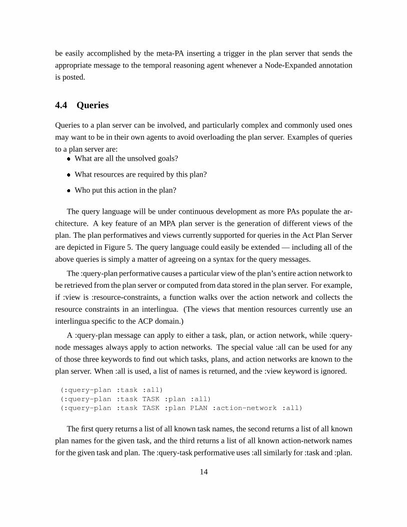
4.4 Queries
Queries to a plan server can be involved, and particularly complex and commonly used ones
may want to be in their own agents to avoid overloading the plan server. Examples of queries
to a plan server are:� What are all the unsolved goals?
� What resources are required by this plan?
� Who put this action in the plan?
The query language will be under continuous development as more PAs populate the ar-
chitecture. A key feature of an MPA plan server is the generation of different views of the
plan. The plan performatives and views currently supported for queries in the Act Plan Server
are depicted in Figure 5. The query language could easily be extended — including all of the
above queries is simply a matter of agreeing on a syntax for the query messages.
The :query-plan performative causes a particular view of the plan’s entire action network to
be retrieved from the plan server or computed from data stored in the plan server. For example,
if :view is :resource-constraints, a function walks over the action network and collects the
resource constraints in an interlingua. (The views that mention resources currently use an
interlingua specific to the ACP domain.)
A :query-plan message can apply to either a task, plan, or action network, while :query-
node messages always apply to action networks. The special value :all can be used for any
of those three keywords to find out which tasks, plans, and action networks are known to the
plan server. When :all is used, a list of names is returned, and the :view keyword is ignored.
(:query-plan :task :all)(:query-plan :task TASK :plan :all)(:query-plan :task TASK :plan PLAN :action-network :all)
The first query returns a list of all known task names, the second returns a list of all known
plan names for the given task, and the third returns a list of all known action-network names
for the given task and plan. The :query-task performative uses :all similarly for :task and :plan.
14

Plan Performative Viewsfor tasks:
:query-task :task-network :assumptionsfor plans:
:query-plan :task-network :subplans:ascii :ascii-filename:monitors :monitor-filename:parent :available-resources
for action networks::query-plan :task-network :resource-constraints
:ascii :ascii-filename:monitors :monitor-filename:resource-allocations
:query-node :predecessors :successors:unrelated
Figure 5: Plan Performatives and Views for Queries
4.5 Act Plan Server
We have implemented a specific plan server, named the Act Plan Server, which employs the
Act formalism [16] for action representation. An Act is the basic structure used to represent
a plan or action network in the Act formalism. Acts can be expressed either in a format
with embedded graphical information or in plain-text format (to facilitate translation to other
languages). The Act-Editor system [9, 17] supports the graphical creation, manipulation,
browsing and display of Acts, thus serving as a graphical knowledge editor for systems that
use Act.
The Act Plan Server is implemented as a PRSagent. PRSis responsible for maintaining an-
notations, handling and distributing incoming messages, and executing triggers appropriately.
PRS uses knowledge encoded in the Act formalism, MPA’s common plan representation, and
is built on the Act-Editor which can display plans graphically.
Several other architectures, including the AITS, use plan servers. Often such plan servers
are required to provide (among other features) persistence, access control, versioning, and
browsing capabilities. While we view all these features as desirable in an MPA plan server, it
is beyond the scope of MPA to implement a plan server with all of these properties.
15
Rather, we have implemented an Act Plan Server with several features not in other plan
servers. MPA uses these new features (e.g., views, triggers and annotations) to control com-
plex planning processes. The goal of MPA is to develop a new, more powerful architecture,
and our Act Plan Server is a step in that direction. We view it as a straightforward effort to
build the Act Plan Server on top of a plan server or database system that will provide the above
AITS plan server features, although the task may require a significant amount of effort.
The Act Plan Server stores a plan as a series of action networks that together form one
alternative plan for a given task. Action networks are stored as Acts (with links to other action
networks in the same plan), and the only persistence provided is that Acts can be saved to
files in their entirety. Alternative plans can be stored for the same task. No access control or
versioning is provided (other than the ability to store alternative plans for the same task), and
the only browsing capabilities are those provided by SRI’s Act-Editor.
The Act Plan Server supports a reasonably broad set of queries, at the level of tasks, plans,
and action networks. For example, queries can be used to extract the set of known tasks,
the set of plans for a given task, and the set of action networks for a given task or plan.
Annotations and triggers can be queried with a fairly general query language. Seven different
views on plans and action networks, and three different views on individual action-network
nodes (actions) can be obtained through queries. The Act Plan Server could easily support
more queries as needed, including access to individual plan and action-network components.
5 Planning-Cell Managers
A cell manager is a persistent agent that can continuously accept tasks from other agents
(human or software), decompose those tasks into subtasks to be performed by its cell agents,
and then combine the results into solutions.
A planning cell can operate as a stand-alone problem-solving unit. Additionally, sets of
planning cells can be aggregated into larger cells, which are in turn controlled by ameta
planning-cell manager, which distributes and coordinates planning tasks among planning
cells. This manager is given a set of tasks to solve and a set of planning cells as resources,
and is responsible for overseeing the entire planning process. Different management schemes
are appropriate for different applications. We have focused on generating multiple plans in
parallel, using a pair of planning cells controlled by a meta planning-cell manager.
16

Here, we describe implementations of both a baselevel cell manager (the PCM), and a
meta planning-cell manager (the meta-PCM). Their designs serve as templates for additional
types of planning cells. In the long term, MPA will contain a library of such templates which
users can adapt as appropriate for their applications.
We have implemented one particular cell manager, the PCM, with a small number of dif-
ferent planning styles. Instances of PCM are used to control each of several planning cells.
In addition, we have implemented a particular instance of a meta planning-cell manager, the
meta-PCM. These agents are described in more detail in Sections 5.1 and 5.2.
Both the meta-PCM and the PCM are implemented as PRS agents. As with any PRS
agent, each agent includes a database for representing declarative knowledge, a set of Acts
that encode procedural knowledge about how to accomplish goals, and LISP functions that
implement the basic activities for the agent, such as sending an MPA message to another cell
agent. SRI has made the meta-PCM and PCM Acts available to the ARPI community.
PRS provides several capabilities that make it a good framework for constructing such
managers. Because cell managers direct the activities of multiple agents, they must be capa-
ble of smoothly interleaving responses to external requests with internal goal-driven activities.
The uniform processing of goal- and event-directed behavior within PRS is ideal for support-
ing such behavior. PRS supports parallel processing within an agent, thus enabling multiple
lines of activity to be pursued at any given time. The database facility within PRS enables
declarative encodings of key characteristics, making them easy to access and modify. The
Act language, used to represent procedural knowledge within PRS, provides a rich set of goal
modalities for encoding activity, including notions of achievement, maintenance, testing, con-
clusion, and waiting. Finally, the extensive textual and graphical tracing in PRS provides
valuable runtime insights into the operation of cell managers.
5.1 Meta Planning-Cell Manager
The meta-PCM is a persistent agent that can continuously accept planning requests and gener-
ate multiple plans for one or more tasks, given a set of planning cells as resources. Tasks can
be specified by either a human user or another planning agent.
The meta-PCM accepts an asynchronous stream of planning request messages(from mul-
tiple agents), each of which can request that multiple plans be produced. For each requested
plan, the meta-PCM will find a free planning cell if one exists. A planning cell can refuse a
17
Plan Performative Communication Performative:solution Tell:failed:multiple-solve Evaluate:define-advice:new-agent:ping
Figure 6: Meta-PCM Plan and Communication Performatives
task if it is already occupied (our PCM agent will always do so). The meta-PCM distributes
tasks to planning cells by sending messages to the cell manager of each cell. These messages
take the form of planning tasks and advice about how to solve the task. The meta-PCM may
distribute only a subset of the requests if planning cells are busy.
The meta-PCM also responds to any messages from planning cells that describe a solution
or a failure for a planning request. (These are sent by cell managers immediately upon finding
a solution or detecting a failure.) Such responses can be done simultaneously with the handling
of new requests. The plans or failures are “forwarded” to the correct requestor by sending an
MPA message. The meta-PCM also notices when all requests from a given incoming message
have been serviced, and prints a summary of the solutions in its trace window. If desired, it
could also send a summary message to the requestor or invoke a plan comparison agent.
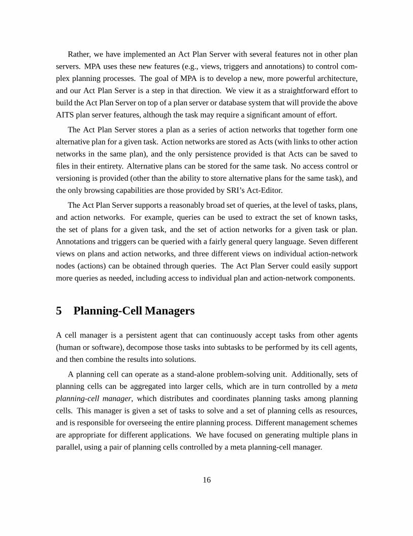
The currently allowed combinations of communication and plan performatives in the mes-
sages handled by the meta-PCM are shown in Figure 6. Multiple-solve messages are the
incoming planning requests. Define-advice messages define new pieces of advice and are for-
warded to all running planning-cell managers. Solution and Failed messages report results
from planning cells. A New-agent message can be used to declare a new planning cell. Sec-
tion 7.1 explains the role of the meta-PCM during our demonstration.
The user can interact directly with the meta-PCM through the PRS interface by posting
appropriate goals and adding or retracting information from the plan server. In addition, an
MPA-specific Meta-PCM menu has been added to the PRS interface to enable simpler inter-
actions with the meta-PCM.
18
Plan Performative Communication Performative:annotation Tell:advice:pcd:solve Evaluate:define-advice:ping
Figure 7: PCM Plan and Communication Performatives
5.2 Overview of the PCM
The PCM is a persistent agent that can continuously solve planning tasks. Tasks can be spec-
ified by either a human user or another planning agent, such as the meta-PCM. Planning
requests are serviced sequentially rather than concurrently; thus, the PCM can solve multiple
tasks but only one at any given time. If the PCM gets a request to generate a plan while it is
already busy, it replies with a message indicating that it is busy. Concurrent plan generation is
accomplished by the meta-PCM, which can invoke multiple PCM agents controlling multiple
planning cells.
A cell manager is responsible for overseeing the entire planning process for a given task.
One key responsibility is the management of the PCD. The agents with assigned roles in the
PCD are referred to as thecell agents. In addition, the cell manager must determine the
appropriate problem-solving strategy to apply to a given task, and manage the distribution of
subtasks to agents within the cell. Finally, the cell manager must coordinate all results and
activities of the cell agents.
Section 7.1 describes the different strategies used by the PCM for monitoring and con-
trolling the planning process during our initial demonstration. The PCM reconfigured the
planning cell during planning and demonstrated dynamic strategy adaptation.
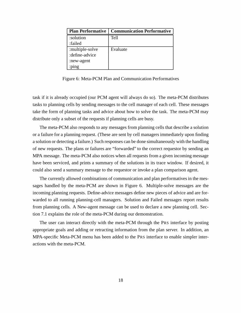
The currently allowed combinations of communication and plan performatives in mes-
sages handled by the PCM are shown in Figure 7. Annotation messages advise the PCM
of annotations that have been posted in the plan server. Such messages are sent by triggers
posted by the PCM itself. Advice messages select (predefined) problem-solving advice [8] to
be used by plan generation agents within the cell; the PCM will pass along specified advice to
appropriate agents when making planning requests. Define-advice messages are forwarded to
appropriate cell agents when new advice is being defined. Solve messages request the PCM
19
PCD Role Agent Names:manager pcm:plan-server plan-server:planner sipe:search-manager:critic-manager:scheduler opis:temporal-reasoneropis, tachyon:executor executor:requestor meta-pcm
Figure 8: Plan Cell Descriptor Roles and Their Possible Fillers
to generate a plan, and Ping and PCD messages are handled by all agents.
5.3 Planning Cell Characteristics
The PCM’s planning cell is characterized by two key elements: the PCD, and theplan styleto
be used for problem solving.
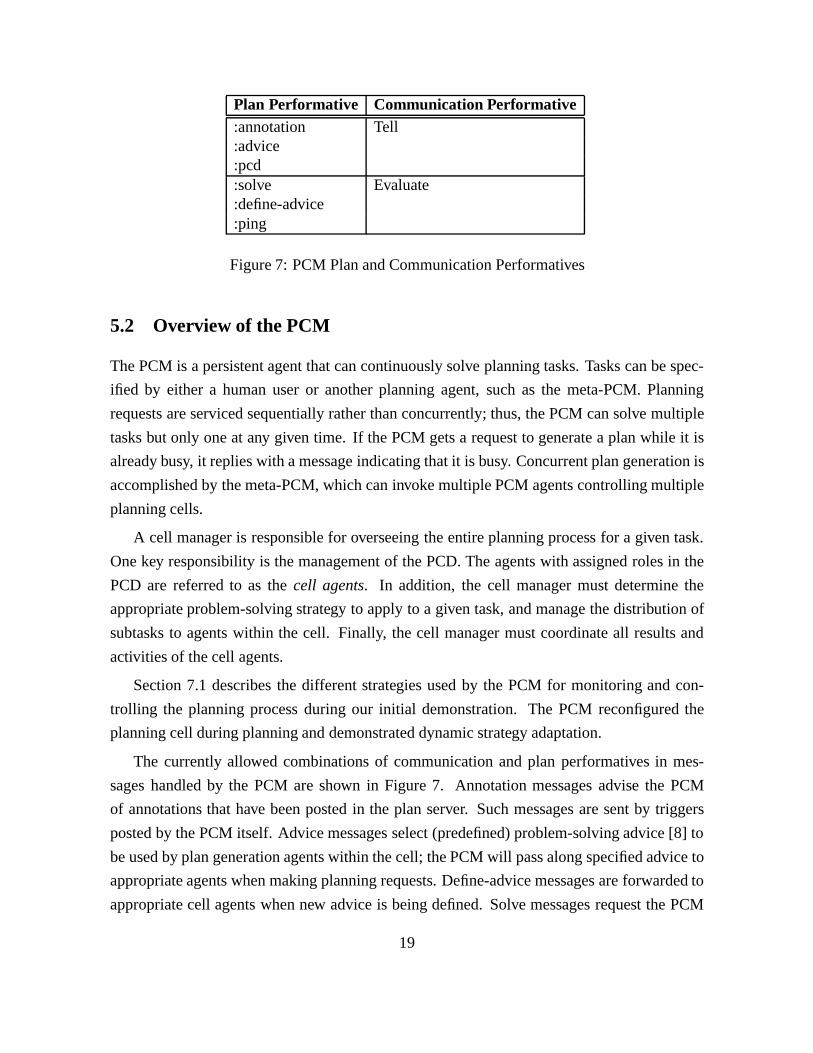
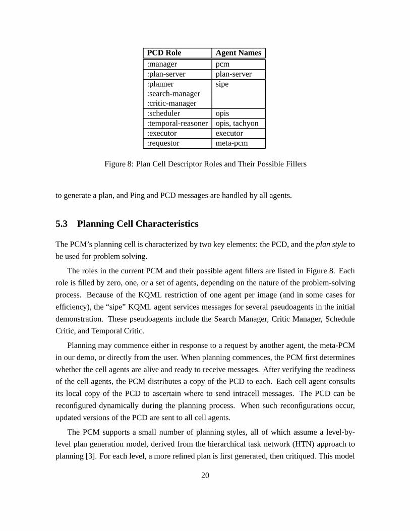
The roles in the current PCM and their possible agent fillers are listed in Figure 8. Each
role is filled by zero, one, or a set of agents, depending on the nature of the problem-solving
process. Because of the KQML restriction of one agent per image (and in some cases for
efficiency), the “sipe” KQML agent services messages for several pseudoagents in the initial
demonstration. These pseudoagents include the Search Manager, Critic Manager, Schedule
Critic, and Temporal Critic.
Planning may commence either in response to a request by another agent, the meta-PCM
in our demo, or directly from the user. When planning commences, the PCM first determines
whether the cell agents are alive and ready to receive messages. After verifying the readiness
of the cell agents, the PCM distributes a copy of the PCD to each. Each cell agent consults
its local copy of the PCD to ascertain where to send intracell messages. The PCD can be
reconfigured dynamically during the planning process. When such reconfigurations occur,
updated versions of the PCD are sent to all cell agents.
The PCM supports a small number of planning styles, all of which assume a level-by-
level plan generation model, derived from the hierarchical task network (HTN) approach to
planning [3]. For each level, a more refined plan is first generated, then critiqued. This model
20
may not apply to all planners, but is reasonably general. In particular, nothing is assumed
about what comprises a level, thus enabling a range of different level refinement methods (for
example, expansion of a single goal or all goals).
A planner can expand a plan to some arbitrary extent, as appropriate to its planning tech-
nology. All that is required is that the plan critics can be applied after each such expansion.
If critic roles are left unfilled, critiquing is skipped. In addition to HTN planners, causal-link
planners [12] fit naturally into this scheme, with goal selection, operator selection, and subgoal
generation viewed as forms of plan expansion. Causal link protection and checking constraint
consistency correspond to plan critiquing.
The PCM planning styles vary in their choice of agent to perform the plan refinement,
the selection of critic agents for the critique phase, and the frequency of critic invocation.
Currently, the PCM supports two plan styles: one where the Planner is responsible for cri-
tiques, and one where the PCM is responsible. The PCM takes different actions based on the
information returned by the Planner about the status of the expansion process.
The PCM-controlled critique phase involves the application of all critics that are currently
declaredfor the Plan Cell. Each declaration defines a critic performative and the cell role that
is responsible for managing the corresponding critic. A critic performative is simply a plan
performative that is handled by an agent that is considered to be a plan critic. The PCM sends
a message to invoke each declared critic.
5.4 PCM Invocation
The user can invoke the PCM through the PRS interface by posting appropriate goals and
adding or retracting facts from the PCM’s database. This is made possible by the declarative
approach used to encode relevant PCM characteristics. In addition, an MPA-specific Plan-Cell
menu has been added to the PRS interface for interactive control of the PCM.
Alternatively the operation of the PCM can be controlled by another agent. We have
implemented a meta-PCM agent which can coordinate the operation of multiple planning
cells to produce multiple plans simultaneously. The meta-PCM, described in Section 5.1,
distributes tasks to planning cells by sending messages to the cell manager of each cell, and
handles messages about completed or failed plans.
21

6 Integrating Planning, Scheduling and Execution
The previous sections described agents that were written specifically for MPA, the meta-PCM,
the PCM, and the Act Plan Server. Here we describe the modularization of legacy software
systems into MPA agents. We first describe the use of executor and plan manager agents for
continuous planning and execution, and then the use of an existing planner and an existing
scheduler in MPA.
6.1 Continuous Planning and Execution
If plans are to be executed in dynamic environments, there must be agents able to deal with
unpredictable changes in the world. As such, agents must be able to react to unanticipated
events by taking appropriate actions in a timely manner, while continuing activities that sup-
port current goals. Agents must have the ability to recover from failures by adapting their
activities to the new situation, and/or repairing the plan. We will refer to an agent with these
capabilites as anexecutoragent, because the MPA protocols described here support the role of
an agent executing a plan and doing plan repair. (As described below, the executor capabilites
are only some of the many desireable functionalities.)
Two different demonstrations show the use of MPA for continuous plan repair. The first
demonstration is a distributed, multiagent version of SRI’s Cypress system in the domain of
joint military operations planning [15]. The second demonstration is a distributed, multiagent
version of SRI’s CPEF system (Continuous Planning and Execution Framework),3 in the do-
main of air campaign planning (using an extended version of the TIE 97-1 planning knowledge
base, but a different scenario).
The executor is always active, constantly monitoring the world for goals to be achieved or
events that require immediate action. In accord with its current beliefs and goals, the executor
takes actions in response to these goals and events. Appropriate responses include applying
standard operating procedures, invoking the planner to produce a new plan for achieving a
goal, or requesting that the planner modify the plan being executed. The planner plans only
to a certain level of detail, with the executor taking that plan and expanding it at run time by
applying appropriate library actions at lower levels of abstraction.
3CPEF development was supported by DARPA Contract No. F30602-97-C-0067 as part of the JFACC pro-gram.
22
Plan Performative Communication Performative:install Evaluate:execute:ping:pcd Tell:solution:failed
Figure 9: Executor Plan and Communication Performatives
CPEF significantly extends the ability of Cypress to support the continuous development,
monitoring, and adaptation of plans. CPEF has a Plan Manager agent that controls the overall
life cycle of a plan, spanning plan generation, plan repairs, and plan execution. Thus, the Plan
Manager performs the duties of the executor agent mentioned above, among other things. The
executor agent could be a separate agent that is invoked by the Plan Manager. The creation
and management ofmonitorsis crucial to plan management. CPEF defines a monitor to be
an event-response rule for which detection of the specified event leads to execution of the
corresponding response. The MPA protocols support the planner automatically generating
monitors appropriate to a specific plan, and sending these monitors to the Plan Manager.
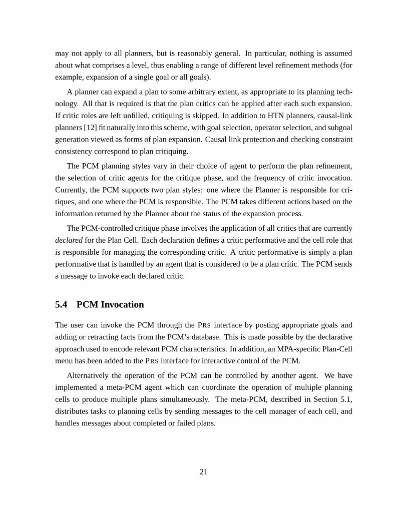
6.1.1 Executor Agent
The MPA protocols described here support the role of an agent executing a plan, possibly do-
ing plan repair. This is one of the many functionalities that a plan manager might provide (e.g.,
a plan manager might control planning agents in a manner similar to the PCM.) The currently
allowed combinations of communication and plan performatives in messages handled by the
executor are shown in Figure 9.
An Install message tells the executor to retrieve the plan from the plan server and get it
ready for possible execution. Installation may involve creating and/or installing monitors. An
Execute message tells the executor to being plan execution. Solution and Failed messages will
be received after Revise or Solve requests are sent to the planner. The executor may also send
Create-monitors requests to the planner.
23
6.2 Planning and Scheduling
One objective of the MPA project is to decompose and integrate planning and scheduling
capabilities within the MPA architecture. Work on integrating planning and scheduling has
proceeded via an SRI subcontract with CMU under the direction of Dr. Steve Smith, aimed
specifically at adapting and integrating scheduling functionality contained in CMU’s OPIS
scheduler [11].4
One of the primary shortcomings of IFD-4 is the inability of the planner to do a capacity
analysis early in the planning process. For example, when there are 75 F-16s and the plan
requires 83 F-16s, the “capacity” of our F-16 assets is inadequate. Part of the MPA decom-
position of the CMU scheduler includes a Scheduler agent for capacity analysis. We have
implemented such an agent and developed its constraint and capacity models. Once we con-
verged on definitions of resource capacity and relevant resource utilization constraints, we
were able to adapt CMU’s capacity analysis knowledge source straightforwardly. We believe
that our demonstration showed significant value added to IFD-4 stemming from the resource
utilization provided by CMU’s scheduler.
6.2.1 Planner Agents: Search Manager and Critic Manager
Currently, the specification for the planner agent assumes a level-by-level plan generation pro-
cess with a critique of the plan after each expansion, as described in Section 5.3. The planner
can expand the plan at each level to some arbitrary extent, as appropriate to the planning tech-
nology being used. The critique can post annotations to the plan server and can cause a failure
of the planning process if unresolvable conflicts are found. The expansion phase is accom-
plished by the Search Manager agent, while the critique of the plan is accomplished by the
Critic Manager agent. Currently, these two agents are pseudoagents within a single planner
agent, although we expect future planning cells will have them as separate agents.
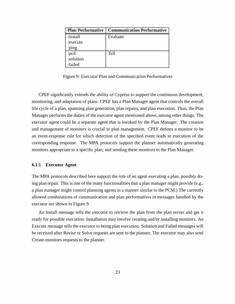
The currently allowed combinations of communication and plan performatives in mes-
sages handled by the Search Manager are shown in Figure 10. The first group of Evaluate
messages are used to generate or modify plans. An Init-problem message translates a given
task to the planner’s representation, and initializes the planner for planning (:start-problem is
a synonym for :init-problem). An Expand-plan message causes the plan to be expanded to
the next level, while an Expand-plan-and-critique message causes the plan to be expanded and
4Steve Smith and Marcel Becker contributed to this section.
24
Plan Performative Communication Performative:init-problem Evaluate:expand-plan:expand-plan-and-critique:generate-plan:revise:define-advice Evaluate:draw-plan:create-monitors:reset-problems:reset-domain:ping:pcd Tell:advice:query-advice Ask-All
Figure 10: Search Manager Plan and Communication Performatives
also calls the plan critics on the plan. A Generate-plan message causes all levels of a plan to be
generated for a given task (using the planner as the only plan-generation agent and bypassing
PCM control). A Revise message causes an existing plan to be modified as required by a set
of new facts given in the message.
The second group of Evaluate messages provide support functions, such as drawing plans,
and updating and querying information. Define-advice messages specify new advice defi-
nitions. A Draw-plan message causes the given plan to be drawn in the planner’s GUI. A
Create-monitors message will create a set of monitors for the given plan (see Section 6.1).
The Advice message tell the planner to activate and/or deactivate already defined pieces of
advice, and the Query-advice message asks the planner to return the names and descriptions
of defined and/or active advice.
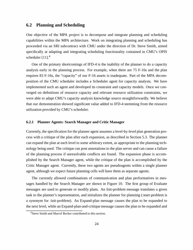
The currently allowed combinations of communication and plan performatives in mes-
sages handled by the Critic Manager are shown in Figure 11. A Plan-ok? message causes the
planner to apply all critics known to it. A Schedule-ok? message causes the agent to invoke
the scheduler agent of the planning cell. A Temporal-ok? message causes the agent to invoke
the temporal-reasoner agent of the planning cell. A Schedule-ctem? message is specific to
the ACP planning domain and causes the planner to translate the current plan to CTEM, run
CTEM, and translate the results back. The Ping and PCD messages are handled by all agents.
25

Plan Performative Communication Performative:plan-ok? Evaluate:schedule-ok?:temporal-ok?:schedule-ctem?:ping:pcd Tell
Figure 11: Critic Manager Plan and Communication Performatives
The domain-independent SIPE–2 planning system [13, 14] and the Advisable Planner [8]
have been used as the basis for the planner agents in all our demonstrations. SIPE–2 has a
precise notion of a planning level, and plan critics that fit naturally into the above scheme. To
serve as an MPA planner agent, SIPE–2 had to be modularized, separating out its search con-
trol algorithm into the Search Manager pseudoagent, its plan critics algorithm into the Critic
Manager pseudoagent, and its temporal reasoning critic into the Temporal Critic pseudoagent,
which was extended to use any temporal reasoner in the planning cell. In addition, a new
critic was created using the scheduler agent to do capacity analysis and resource allocation.
The Schedule Critic pseudoagent was written to interact with whatever scheduler agent is in
the planning cell.
6.2.2 Scheduler Agent
The use of the scheduler in our current implementation is tied closely to the ACP domain.
This domain has been modeled within OPIS to produce a scheduling agent for the planning
cell. This agent currently provides two types of service to support the planning process:
� Capacity analysis - this service provides a profile of the resource demand for airframe
capacity of different types at various air bases over time, and identifies those periods
where the “availability level” of allocated resources indicates that available assets are
oversubscribed.
� Resource allocation - this service commits specific assets (i.e., airframe capacity of a
particular type from a particular airbase) to specific missions and hence declares these
resources unavailable for any subsequent missions that might be planned.
26

Plan Performative Communication Performative:available-resources Ask-all:resource-constraints:allocate-resources Evaluate:ping:pcd Tell:solution
Figure 12: Scheduler Plan and Communication Performatives
The currently allowed combinations of communication and plan performatives in mes-
sages handled by the scheduler are shown in Figure 12. Available-resources and Resource-
constraints messages are simply “forwarded” on to the plan server using the appropriate view
of the given plan, and the plan server’s answer is returned. The primary invocation of the
scheduler is done with an Allocate-resources message which causes the scheduler to analyze
capacity and allocate resources.
7 Single Planning Cell Configuration
We use the termconfigurationto refer to a particular organization of MPA agents and problem-
solving strategies. Here, we describe a single-cell MPA configuration for generating individual
solutions to a planning task, and the next section describes multiple-cell configurations for
generating alternative solutions in parallel.
The initial demonstration was given in September 1996, using the configuration depicted
in Figure 13. The demonstration showed a multiagent planner and scheduler, together with a
temporal reasoning agent, accomplishing planning/scheduling in the Air Campaign Planning
domain. To demonstrate the capabilities of MPA, we showed multiple asynchronous agents
cooperatively generating a plan, the cell manager reconfiguring the planning cell during plan-
ning, agents implemented in different programming languages, and agents running on dif-
ferent machines both locally and over the Internet. The June 1997 demonstration, described
in Section 8, includes multiple instances of the planning cell from the 1996 demonstration,
coordinated by a meta planning-cell manager, producing multiple alternative plans in parallel.
The PCM is a meta-PA that controls the entire process, including initialization of the
planning cell, and specification of a Planning-Cell Descriptor. Planning agents include
27

Plan Complete
Plan ok?
PAScheduler(OPIS)
PATemporal Reasoner(OPIS)
PATemporal Reasoner(Tachyon)
or
PA Search Managerone-level(SIPE-2)
PASchedule Critic(new)
PATemporal Constraint Critic(SIPE-2)
RequestExpandNextLevel
Meta-PAPlanning-Cell Manager(PRS)
Planning Cell Designator
Cue: (TEST (ready unit1))ACT2
Cue: Plan One-Level
ACT1Create a planAgent
KQML
Message
Annotations
Triggers
Plan Server
Cue: (TEST (ready unit1))ACT2Cue: Answer query
ACT1
meta-PACritic Manager(SIPE-2)
Figure 13: MPA Single Cell Configuration. Arrows represent message traffic, except that allagents communicate with the (Act) Plan Server so those arrows are omitted. The lines withoutarrowheads show planning cell composition, and the shaded boxes were not implemented.Agents insides dashed boxes were implemented within the same image.
GUI/Advice-Manager (not implemented until TIE 97-1), Act Plan Server, Search Manager,
Critic Manager, Schedule Critic, Temporal Critic, Scheduler, and Temporal Reasoner (pro-
vided by OPIS, Tachyon, or both).
The PCM and the Act Plan Server are implemented in PRS, which allows complex real-
time control of the processing of messages. Eventually, the Critic Manager may also be a PRS-
based meta-PA that controls agents for individual critics. Currently, SIPE–2’s critic manager
is the basis for the Critic Manager, although it has been modified to send messages to temporal
reasoning and scheduling agents. The Tachyon agent is in C and employs a C wrapper, while
the other agents have LISP wrappers.
All agents send messages to and from the Act Plan Server, so arrows for these messages
are omitted. The Act Plan Server supports annotations and triggers which are used to record
features of the plan and notify agents of the posting of those features. The plan is written to the
plan server in the Act formalism, which can be understood by the scheduler and the planner.
The Act Plan Server answers queries about the plan, and handles the annotations and triggers.
28
The Search Manager is based on SIPE–2’s interactive search routine, which has been ex-
tended to record its backtracking points and other information in the plan server. Another
extension permits starting the search at various backtracking points.
7.1 Control of the Planning Process
The demonstration involves strategy-to-task planning in which the PCM controls the interac-
tion among the various components. The demonstration proceeds through the three phases de-
scribed here. Because of the specialized nature of the task, a special Act (Multiphase Planning
with CTEM) is included in the procedural knowledge base of the PCM to enable generation of
plans that require CTEM invocation.5
Phase I: Targeting Plans The first phase produces the initial targeting plans for achiev-
ing air superiority. For this phase, no scheduler capabilities are used, as there is nothing to
schedule in this phase.
Phase II: CTEM Analysis The second phase consists of CTEM scheduling the Phase I
plan. This request is made by sending a :schedule-ctem performative to the cell’s Planner.
Phase III: Support Plan In the final phase, the support missions required for the CTEM-
generated schedule are generated by a second planning process. This portion of the task
requires scheduling, so the PCM modifies the PCD to include “opis” in the role of scheduler
and redistributes the new PCD to all cell agents.
7.2 Demonstration Scenario
The demonstration generates a two-day plan to achieve air superiority over two unnamed coun-
tries. We extended IFD-4 by adding some Intelligence Surveillance Reconnaissance (ISR)
operators with temporal constraints (the ISR must be sometimes be done several days before
other actions). The PCM invokes the Temporal Reasoner to check these constraints.
The demonstration develops a plan in which fuel tankers are overutilized. When the Sched-
ule Critic notices the Resources-Overutilized annotation posted by the Scheduler for specific
5CTEM is a force requirements estimator and scheduler developed at AEM Services.
29
tankers, it inserts a Resource-Class-Overutilized annotation for the class of tankers. The PCM
has posted a trigger on such an annotation and is immediately notified. It responds with two
different tactics to produce a better plan:
1. The PCM sends an :advice plan performative to the Planner, which causes the Plannerto choose options requiring less fuel for the remainder of the plan expansion. Thiscapability employs SRI’s Advisable Planner. The plan will still have flaws becauseresources were already overutilized before the PCM issued the advice.
2. The PCM (after either finishing tactic (1) or aborting the planning process) invokes asecond search for another plan, this time using advice from the start. This produces afuel-economic plan in which tankers are not overutilized.
This scenario shows the flexibility provided by the MPA. Separate software systems (OPIS,
Tachyon, and SIPE–2, using KQML and PRSfor support), cooperatively generate a plan. They
are distributed on different machines, implemented in different programming languages, and
combined in multiple ways because of the flexible architecture. The Act Plan Server allows
flexible communication of the plan among agents. The PCM encodes different strategies
for monitoring and controlling the planning process, thus demonstrating dynamic strategy
adaptation in response to partial results.
8 Multiple Planning Cell Demonstrations
In June 1997, we demonstrated a configuration with two planning cells producing alternative
plans for the same task in parallel. The TIE 97-1 demonstration built on this configuration,
but used a new and more extensive knowledge base of planning operators and advice, and
integrated additional agents.
The meta-PCM controls the entire process, including initialization of planning cells, dis-
tribution of tasks and advice, and reporting of solutions. The planning cells operate exactly as
described for the single planning cell demonstration (Section 7), except that they are invoked
by the meta-PCM instead of the user, and they refuse requests if they are already busy.
8.1 June 1997 Demonstration
This demonstration followed the same sequence as that for the single planning cell demon-
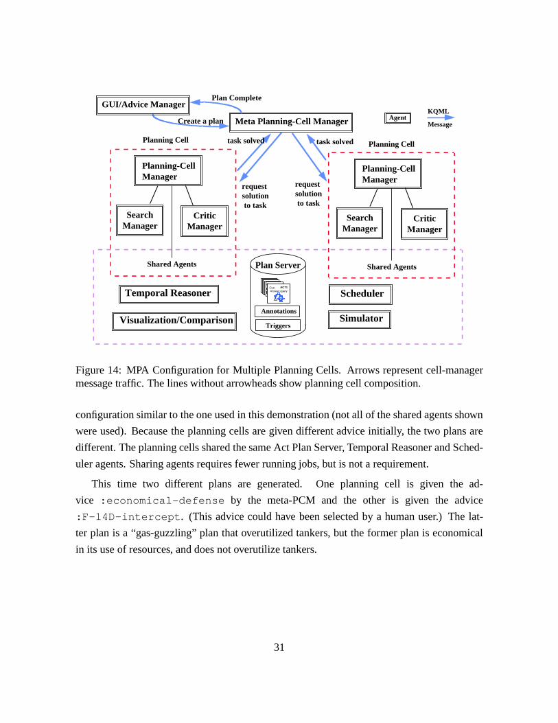
stration, except two alternate plans are constructed in parallel. Figure 14 depicts a multicell
30
Visualization/Comparison
AgentKQML
Message
Annotations
Triggers
Plan Server
Cue: (TEST (ready unit1))ACT2Cue: Answer query
ACT1
Scheduler
Planning Cell Planning Cell
Meta Planning-Cell Manager
task solved task solved
request solutionto task
request solutionto task
Shared Agents
SearchManager
CriticManager
Planning-Cell Manager
Create a plan
Plan Complete
Simulator
Temporal Reasoner
Shared Agents
SearchManager
CriticManager
Planning-Cell Manager
GUI/Advice Manager
Figure 14: MPA Configuration for Multiple Planning Cells. Arrows represent cell-managermessage traffic. The lines without arrowheads show planning cell composition.
configuration similar to the one used in this demonstration (not all of the shared agents shown
were used). Because the planning cells are given different advice initially, the two plans are
different. The planning cells shared the same Act Plan Server, Temporal Reasoner and Sched-
uler agents. Sharing agents requires fewer running jobs, but is not a requirement.
This time two different plans are generated. One planning cell is given the ad-
vice :economical-defense by the meta-PCM and the other is given the advice
:F-14D-intercept . (This advice could have been selected by a human user.) The lat-
ter plan is a “gas-guzzling” plan that overutilized tankers, but the former plan is economical
in its use of resources, and does not overutilize tankers.
31
8.2 TIE 97-1 Demonstration
The TIE 97-1 demonstration, first shown in November 1997, built directly on the multiple
planning-cell demonstration just described. Significant extensions include the use of a new
and more extensive knowledge base, and the integration of additional agents for plan evalua-
tion, user interaction and plan visualization. Figure 14 depicts the configuration used in this
demonstration.
Several new MPA agents were created. The ARPI Plan Authoring Tool (APAT) from ISX,
a legacy system written in Java, was integrated as an MPA agent. It fills two roles, the first
being the role of GUI/Advice Manager depicted in Figure 14, and the second being the role
of plan visualization (a service also provided in the demonstration by the Visage system from
MAYA). Another new agent was the Air Campaign Simulator (ACS) [1] from the University
of Massachusetts, written in LISP, whose role was to run Monte Carlo simulations of plans,
and feed the resulting data to the VISAGE system from MAYA for plan visualization and
evaluation. Both of these agents can read Acts from the Act Plan Server and translate them to
their internal representation.
It took the University of Massachusetts only a day to download MPA and have ACS send-
ing and receiving MPA messages. A few more days were needed for translating from the Act
representation into the ACS representation. (This translation is easy because ACS can ignore
much of the information in an Act.)
This experience indicates that MPA does indeed facilitate the integration of new technolo-
gies. To have a technology like ACS be invoked by APAT and retrieve the plan from the agents
producing it took much longer in IFD-4 (before MPA).
8.2.1 ACP Knowledge Base
We built a new knowledge base (ACP KB) for the air campaign planning domain. The ACP
KB is intended to support air superiority planning, both offensive and defensive, down to ac-
tivity and support mission level. The ACP KB now models target networks. Each network
provides a capability and requires capabilities from other networks in order to function. Net-
work effectiveness is modeled quantitatively, allowing incremental degradation.
The network/capability model is used primarily to model threats to air superiority, though
the model is rich enough to model production networks, lines of communication, and other
32
networks of targets. The new KB allows more sophisticated and realistic effects-based plan-
ning than was done in IFD-4. For example, it keeps track of target networks (not present in
IFD-4) and calculates degradation of the network as targets are attacked. The ACP KB adds
more realism and provides a more substantive integration with the simulator, the Advisable
Planner, and plan critique and evaluation modules than the old knowledge base.
8.2.2 Demonstration Flow
The user interacts with APAT, specifying part of the plan and selecting advice to control the
automatic generation of the air superiority plan. As of September 1998, the user can easily
create new advice using the Mastermind tool6 to generate legal advice definitions which are
then sent to all appropriate agents.
The APAT-authored plan is written as an Act to the plan server. When requested by a
human using APAT’s GUI, APAT sends a message to the meta-PCM with the user-selected
advice requesting a plan to be generated. The meta-PCM invokes a planning cell on the
request, using all the agents of our earlier demonstrations except the temporal reasoner. This
planning process uses both the MPA-generated plan and the APAT-authored plan as input to
CTEM, and then generates a support plan for the CTEM output.
When the post-CTEM plan is finished, APAT retrieves the plan by sending a message to
the plan server, and translates it to APAT’s internal representation. The user can use APAT’s
GUI to inspect the plan. Interacting with APAT, the user elects to simulate the plan, and a
message is sent to invoke ACS on the generated plan. ACS retrieves the plan by sending
a message to the plan server, and generates data by simulating the plan. VISAGE is then
invoked to visualize the results of the simulation.
The user does not like certain aspects of the plan, so decides to generate two different
alternatives, and selects two sets of advice in APAT. A message is sent to the meta-PCM
requesting two plans. Two planning cells are invoked in parallel and two plans are generated.
Again, simulation is invoked, and this time VISAGE can display graphs and charts comparing
all three plans along various dimensions.
6from Information Sciences Institute (ISI).
33
9 Future Work
Promising directions for extending this work are numerous. They include the following:
� Experimenting with additional configurations and cooperative problem-solving meth-ods.
� Broadcasting messages to fill planning cells with agents.
� Defining a broader range of cell-manager control strategies and planning styles.
� Incorporating additional technologies as new agents.
� Extending the plan server (possible extensions include the plan representation, accesscontrol to the plan, version control, and graphical browsing capabilities).
10 Summary
MPA is an open planning architecture that facilitates incorporation of new technologies and
allows the planning system to capitalize on the benefits of distributed computing for efficiency
and robustness. MPA provides protocols to support the sharing of knowledge and capabili-
ties among agents involved in cooperative problem-solving. Within MPA, software modules
written in different programming languages can easily interoperate.
MPA configurations show the flexibility provided by MPA. Separate software systems
(OPIS, Tachyon, ACS, APAT, the Advisable Planner, and SIPE–2, using KQML, the Act-
Editor, and PRS for support) cooperatively generate and evaluate plans, generating multiple,
alternative plans in parallel. These systems are combined in multiple ways through the flexible
architecture.
The MPA framework has been used to integrate several sophisticated stand-alone systems
cooperating on a large-scale problem. The MPA configuration generated and evaluated com-
plex plans (containing more than 4000 nodes) in the ACP domain, and included agents written
in C, C++, LISP, and Java. MPA was used as the infrastructure for ARPI’s TIE 97-1.
The Act Plan Server allows flexible communication of the plan among agents through the
use of annotations, triggers, and views. The PCM encodes different strategies for controlling
the planning process, demonstrating dynamic strategy adaptation in response to partial results.
The planner and scheduler use legacy systems to provide a new integration of planning and
scheduling technologies.
34
Other sites have been able to download the MPA wrapper and get an existing LISP program
communicating as an MPA agent in one day. Our experience indicates that MPA does indeed
facilitate the integration of new technologies, thus encouraging experimentation with and use
of new technologies.
Acknowledgments
This research was supported by Contract F30602-95-C-0235 with the Defense Advanced Re-search Projects Agency, under the supervision of Air Force Research Lab – Rome. Tom Leemade significant contributions, and was responsible for the ACP KB.
References
[1] Paul Cohen, Scott Anderson, and David Westbrook. Simulation for ARPI and the AirCampaign Simulator. In A. Tate, editor,Advanced Planning Technology: TechnologicalAchievements of the ARPA/Rome Laboratory Planning Initiative, pages 113–118, AAAIPress, Menlo Park, CA, 1996.
[2] E. H. Durfee, M. J. Huber, M. Kurnow, and J. Lee. Taipe: Tactical assistants for interac-tion planning and execution. InProceedings of Autonomous Agents ’97, 1997.
[3] Kutluhan Erol, James Hendler, and Dana S. Nau. Semantics for hierarchical task-network planning. Technical Report CS-TR-3239, Computer Science Department, Uni-versity of Maryland, 1994.
[4] T. Finin, J. Weber, G. Wiederhold, M. Genesereth, R. Fritzson, D. McKay, andJ. McGuire. Specification of the KQML Agent-Communication Language. TechnicalReport EIT T R92-04, Enterprise Integration Technologies, Palo Alto, CA, 1992.
[5] Bill Janssen, Mike Spreitzer, Dan Larner, and Chris Jacobi. ILU 2.0 reference manual.Technical report, Xerox PARC, December 1997.
[6] P.D. Karp, J.D. Lowrance, T.M. Strat, and D.E. Wilkins. The Grasper-CL graph man-agement system.LISP and Symbolic Computation, 7:245–282, 1994.
[7] Douglas B. Moran, Adam J. Cheyer, Luc E. Julia, David L. Martin, and Sangkyu Park.Multimodal user interfaces in the Open Agent Architecture. InProc. of the 1997 Interna-tional Conference on Intelligent User Interfaces (IUI97), Orlando, Florida, 6-9 January1997.
35
[8] Karen L. Myers. Strategic advice for hierarchical planners. In L. C. Aiello, J. Doyle,and S. C. Shapiro, editors,Principles of Knowledge Representation and Reasoning: Pro-ceedings of the Fifth International Conference (KR ’96). Morgan Kaufmann Publishers,1996.
[9] Karen L. Myers and David E. Wilkins.The Act-Editor User’s Guide: A Manual for Ver-sion 2.2. Artificial Intelligence Center, SRI International, Menlo Park, CA, September1997.
[10] Karen L. Myers and David E. Wilkins.The Act Formalism. Artificial Intelligence Center,SRI International, Menlo Park, CA, version 2.2 edition, September 1997.
[11] Stephen Smith. Opis: A methodology and architecture for reactive scheduling. In M. Foxand M. Zweben, editors,Intelligent Scheduling. Morgan Kaufmann Publishers Inc., SanMateo, CA, 1994.
[12] D. S. Weld. An introduction to least committment planning.AI Magazine, 15(4):27–61,1994.
[13] David E. Wilkins. Practical Planning: Extending the Classical AI Planning Paradigm.Morgan Kaufmann Publishers Inc., San Mateo, CA, 1988.
[14] David E. Wilkins. Can AI planners solve practical problems?Computational Intelli-gence, 6(4):232–246, 1990.
[15] David E. Wilkins and Roberto V. Desimone. Applying an AI planner to military op-erations planning. In M. Fox and M. Zweben, editors,Intelligent Scheduling, pages685–709. Morgan Kaufmann Publishers Inc., San Mateo, CA, 1994.
[16] David E. Wilkins and Karen L. Myers. A common knowledge representation for plangeneration and reactive execution.Journal of Logic and Computation, 5(6):731–761,December 1995.
[17] David E. Wilkins, Karen L. Myers, John D. Lowrance, and Leonard P. Wesley. Plan-ning and reacting in uncertain and dynamic environments.Journal of Experimental andTheoretical AI, 7(1):197–227, 1995.
36