summary of anl’s fy-16 environmentally assisted fatigue ... · summary of anl’s fy-16...
TRANSCRIPT

Work Sponsored by the DOE Light Water Reactor Sustainability Program
Summary of ANL’s FY-16 Environmentally Assisted
Fatigue Work in Support of LWRS Program
16th August 2016
Subh Mohanty, Bipul Barua, William Soppet, Saurin Majumdar, and
Ken Natesan
Nuclear Engineering Division, Argonne National Laboratory
Major Highlights:
Variable Amplitude Fatigue Test & Material Modeling.
3D FE Modeling of PWR Reactor Pressure Vessel and Nozzle under Grid Load-
Following.
Presented by Subh Mohanty

Work Sponsored by the DOE Light Water Reactor Sustainability Program
OUTLINE Background Information
Cyclic-Plasticity Introduction
Experiment: Variable Amplitude Fatigue Test
Material Modeling Based on Variable Amplitude Fatigue Test Data
Cyclic-Plasticity 1-D Analytical Modeling
3D-FE Isothermal Stress Analysis of Fatigue Test Specimen
3D-FE Thermal Analysis of RPV & Nozzles under Grid Load-Following
3D-FE Thermal-Mechanical Stress Analysis of RPV & Nozzles under Grid Load-
Following
Experiment: Grid Load-Following (Random Load ) Fatigue test
Summary & Future Plan

Work Sponsored by the DOE Light Water Reactor Sustainability Program
Background Information
3
Work Sponsored by the DOE Light Water Reactor Sustainability Program
4
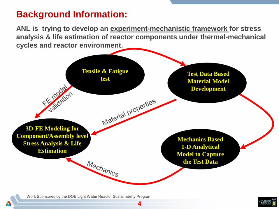
Background Information:
ANL is trying to develop an experiment-mechanistic framework for stress
analysis & life estimation of reactor components under thermal-mechanical
cycles and reactor environment.
4
Mechanics Based
1-D Analytical
Model to Capture
the Test Data
3D-FE Modeling for
Component/Assembly level
Stress Analysis & Life
Estimation
Tensile & Fatigue
testTest Data Based
Material Model
Development

Work Sponsored by the DOE Light Water Reactor Sustainability Program
Cyclic-Plasticity Introduction
5

Work Sponsored by the DOE Light Water Reactor Sustainability Program
Why Cyclic-Plasticity ?
6
Current Industry Approach:
Life estimation based on end of test stress-life (S~N) curve and in general on elastic stress analysis
results.
Generic & Intended Structural Feature of Reactor Components:
In general reactor components are bulky and overdesigned (context of strength)
Stress-strain state in reactor component stays well below the yield stress.
When stress-strain state below yield limit No fatigue or the NPP component has
ideally infinite life.
Why Reactor Component (if only considered SCC) Still Fails ?
Plasticity ?
Environment Residual stress Local stress Load sequence

Work Sponsored by the DOE Light Water Reactor Sustainability Program
Introduction to ANL’s Cyclic Plasticity Model
7
Yield Function:
Convectional Elastic-plastic FE
model: FIXED back stress & Yield
stress parameters
100
101
102
103
200
220
240
260
280
300
320
340
360
Fatigue cycles
Off
set
(yl=
0.0
5%
) y
ield
str
ess
(M
Pa
)
RT-F08 (22 oC, In-air)
ET-F07 (300 oC, In-air)
ET-F17 (300 oC, In-air)
EN-F18 (300 oC, PWR water)
Example offset strain (0.05%) yield limit
stress for 316 SS-316 SS weld specimens
fatigue tested under different conditions (Ref. Mohanty, et al. Nuclear Engineering and Design
305 (2016): 524-530)
ANL’s Elastic-plastic FE modeling
approach: TIME VARYING back
stress & Yield stress parameters
ANL proposed time-dependent
variable Yield and Chaboche model

Work Sponsored by the DOE Light Water Reactor Sustainability Program
Experiment: Variable Amplitude Fatigue Test
8
Work Sponsored by the DOE Light Water Reactor Sustainability Program
9
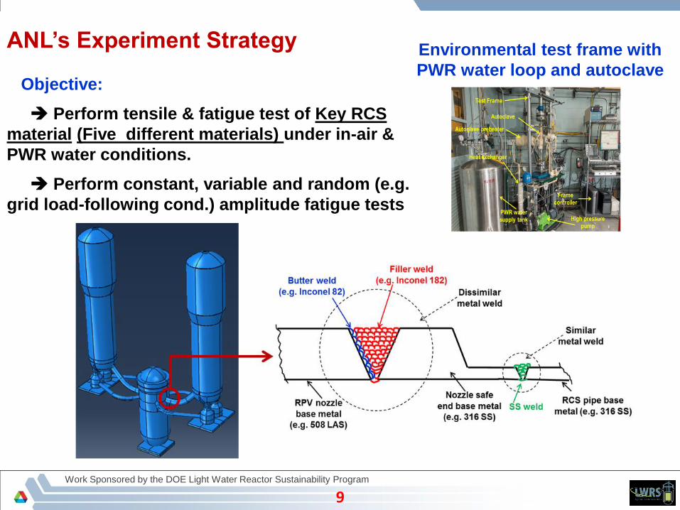
ANL’s Experiment Strategy
Objective:
Perform tensile & fatigue test of Key RCS
material (Five different materials) under in-air &
PWR water conditions.
Perform constant, variable and random (e.g.
grid load-following cond.) amplitude fatigue tests
9
Environmental test frame with
PWR water loop and autoclave

Work Sponsored by the DOE Light Water Reactor Sustainability Program
10
Why it is needed ?
Constant amplitude fatigue test can be used for estimating time dependent
material properties (e.g. yield stress, etc.)
However, it may not capture the effect of loading amplitude and hence load
sequencing effect under random loading (e.g. grid load-following) conditions.
10
Variable amplitude fatigue test
etc.)Amplitude,Loading,Time/Agingnt,(Environme
model)FE(forpropertiesMaterial
f
What we need from variable amplitude fatigue test data?

Work Sponsored by the DOE Light Water Reactor Sustainability Program
1111
Variable amplitude fatigue test results
Variable amplitude (stress control) fatigue test conducted under in-air and
PWR water condition and at 300 oC.
Equivalent
monotonic stress-
strain curve
Example 1st three block applied
stress amplitude
In-air cond. cyclic stress-strain curves for
block-1
In-air cond. cyclic & equivalent monotonic
stress-strain curves for block-1

Work Sponsored by the DOE Light Water Reactor Sustainability Program
Material Modeling Results
12

Work Sponsored by the DOE Light Water Reactor Sustainability Program
1313
Example parameters estimated based on 300 oC, in-air variable
amplitude fatigue test data
Estimated using each block equivalent-
monotonic stress-strain curve to capture the
effect of time and amplitude.
Example property

Work Sponsored by the DOE Light Water Reactor Sustainability Program
Cyclic-Plasticity Analytical Modeling Results
14
Work Sponsored by the DOE Light Water Reactor Sustainability Program
1515
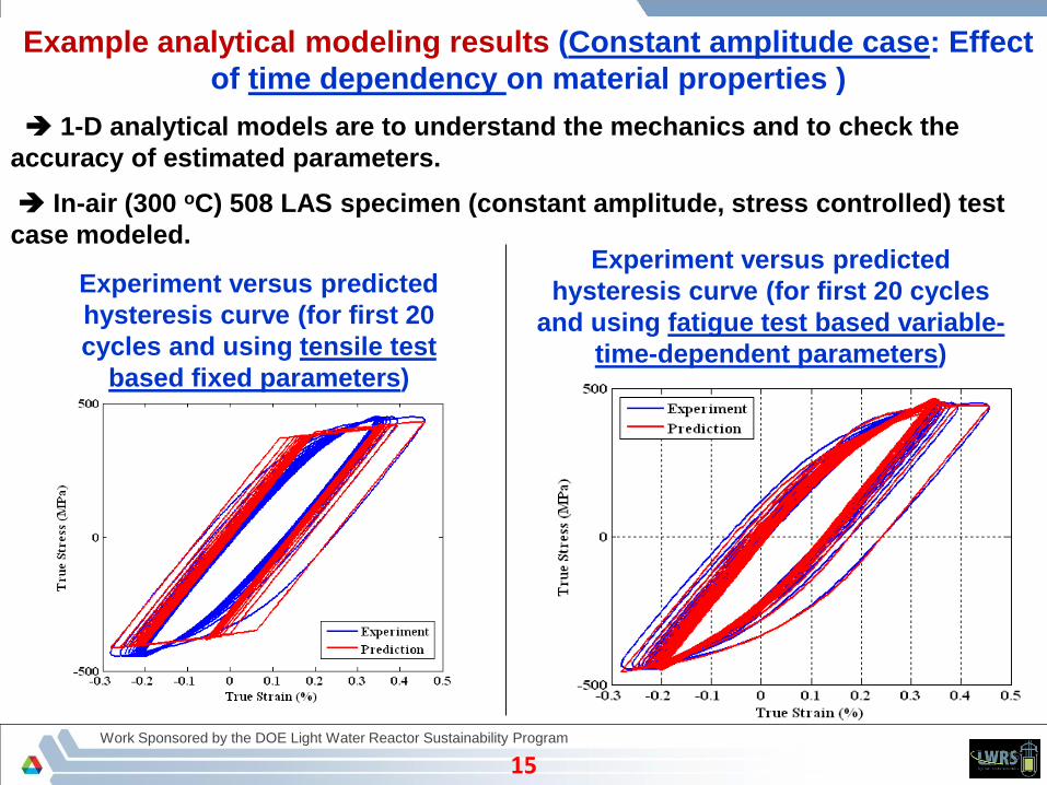
Example analytical modeling results (Constant amplitude case: Effect
of time dependency on material properties )
1-D analytical models are to understand the mechanics and to check the
accuracy of estimated parameters.
In-air (300 oC) 508 LAS specimen (constant amplitude, stress controlled) test
case modeled.
Experiment versus predicted
hysteresis curve (for first 20
cycles and using tensile test
based fixed parameters)
Experiment versus predicted
hysteresis curve (for first 20 cycles
and using fatigue test based variable-
time-dependent parameters)

Work Sponsored by the DOE Light Water Reactor Sustainability Program
1616
In-air (300 oC) 508 LAS specimen (variable-amplitude, stress-controlled) test
case modeled.
This preliminary result shows the importance of variable
amplitude test based parameters
Block-1 prediction based
on tensile test based
parameter
Block-1 prediction
based on 1st quarter
cycle (constant
amplitude fatigue test)
based parameter
Block-1 prediction based
on (variable amplitude
fatigue test) 1st block
based block-averaged
parameters
Example analytical modeling results (Variable amplitude case: Effect of
time & amplitude dependency on material properties )

Work Sponsored by the DOE Light Water Reactor Sustainability Program
3D-FE Isothermal Stress Analysis of Fatigue Test
Specimen
17

Work Sponsored by the DOE Light Water Reactor Sustainability Program
1818
3D-FE model results: PWR water fatigue test specimen
FE model
Earlier estimated 508 LAS (constant amplitude fatigue test) material properties used.
The intention was to check the performance of estimated material parameters with
respect to 3D elastic-plastic FE model.
100
101
102
103
300
320
340
360
380
400
420
440
Fatigue cycles
Off
set
(yl=
0.0
5%
) y
ield
str
ess
(M
Pa
)
RT-F23 (22 oC, In-air)
ET-F24 (300 oC, In-air)
EN-F20 (300 oC, PWR water)
Example time-varying 508 LAS material
properties for different cond.
Example applied crosshead displacement
(stroke) for EN-F20 PWR water test

Work Sponsored by the DOE Light Water Reactor Sustainability Program
1919
Predicted vs experiment
strain
Predicted vs experiment stress
3D-FE model results: PWR water fatigue test specimen (cont.)
This preliminary result shows that the estimated material parameters can
reasonably be used for the 3D-component level FE models

Work Sponsored by the DOE Light Water Reactor Sustainability Program
3D-FE Thermal Analysis of RPV and Nozzles under
Grid Load-following
20
Work Sponsored by the DOE Light Water Reactor Sustainability Program
2121
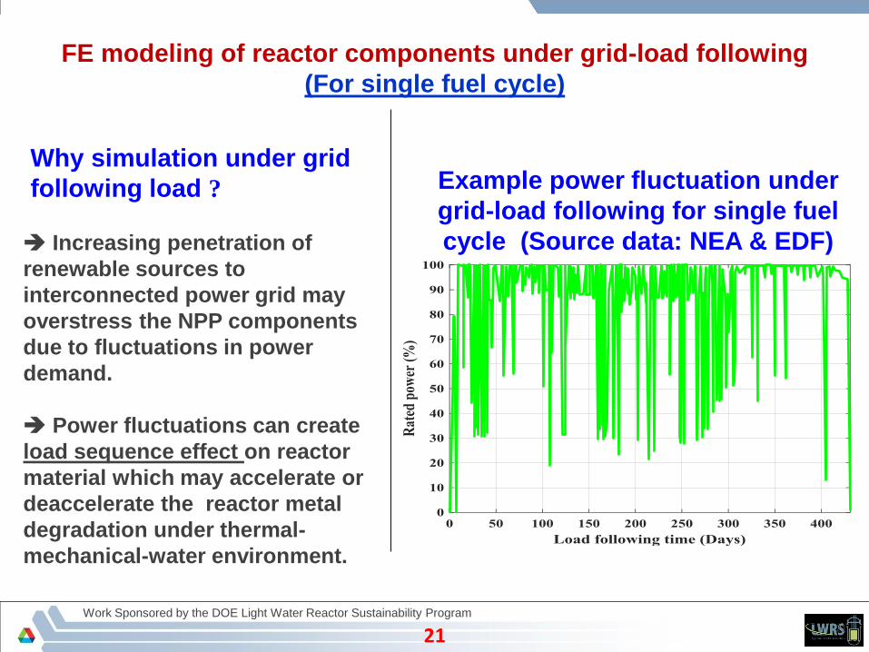
FE modeling of reactor components under grid-load following
(For single fuel cycle)
Why simulation under grid
following load ?
Increasing penetration of
renewable sources to
interconnected power grid may
overstress the NPP components
due to fluctuations in power
demand.
Power fluctuations can create
load sequence effect on reactor
material which may accelerate or
deaccelerate the reactor metal
degradation under thermal-
mechanical-water environment.
Example power fluctuation under
grid-load following for single fuel
cycle (Source data: NEA & EDF)
Work Sponsored by the DOE Light Water Reactor Sustainability Program
2222
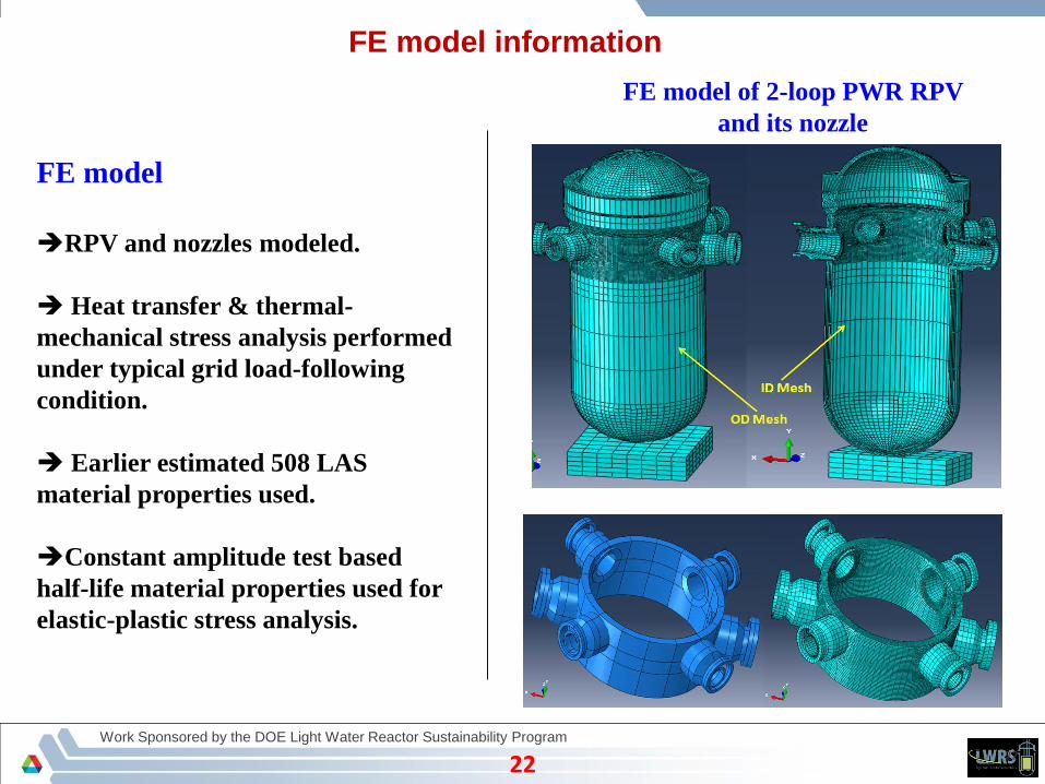
FE model information
FE model
RPV and nozzles modeled.
Heat transfer & thermal-
mechanical stress analysis performed
under typical grid load-following
condition.
Earlier estimated 508 LAS
material properties used.
Constant amplitude test based
half-life material properties used for
elastic-plastic stress analysis.
FE model of 2-loop PWR RPV
and its nozzle

Work Sponsored by the DOE Light Water Reactor Sustainability Program
2323
Heat transfer analysis results under grid load-
following
Temperature boundary condition:
Heat-up-cool-down conditionTemperature boundary condition: normal
operation load-following condition

Work Sponsored by the DOE Light Water Reactor Sustainability Program
2424
0 50 100 150 200 250 300 350 400 450
50
100
150
200
250
300
350
Time (Days)
Tem
pera
ture (
oC
) a
cro
ss H
L n
ozzle
th
ick
ness
X: 395.8
Y: 322.4
Temperature time-history across HL
nozzle thickness with OD surface
ambient boundary condition
Temperature time-history across HL
nozzle thickness with OD surface
insulated boundary condition
0 50 100 150 200 250 300 350 400 450
50
100
150
200
250
300
350X: 395.8
Y: 323.8
Time (Days)
Tem
pera
ture (
oC
) a
cro
ss H
L n
ozzle
th
ick
ness
Heat transfer analysis results under grid load-
following (cont.)

Work Sponsored by the DOE Light Water Reactor Sustainability Program
2525
Temperature distribution (approximately at 391.09 days) with OD surface
a) Ambient and b) insulated condition
Appropriate insulation and thermal properties selection required for accurate estimation of
temporal and spatial distribution of nodal temperature (for further use in stress analysis)
Heat transfer analysis results under grid load-
following (cont.)

Work Sponsored by the DOE Light Water Reactor Sustainability Program
3D-FE Thermal-Mechanical Stress Analysis of RPV
and Nozzles under Grid Load-following
(Case-1: Without presence of simulated SCC crack)
26

Work Sponsored by the DOE Light Water Reactor Sustainability Program
2727
Without crack: Stress analysis results
FE model
Earlier estimated 508 LAS material properties (from half-life stress-strain curves of
constant amplitude fatigue test) used.
In-air vs. PWR water condition properties used to check the effect
FE estimated thermal strain at
typical element of CL nozzle
FE estimated thermal strain at
typical element of HL nozzle

Work Sponsored by the DOE Light Water Reactor Sustainability Program
2828
FE estimated total strain at
typical element of CL nozzle
FE estimated total strain at
typical element of HL nozzle
The overall aim of ANL’s LWRS work objective is to capture the effect of environment,
mechanistically (e.g. through generic material properties) rather than through end of life
based stress-life curves.
Without crack: Stress analysis results (cont.)
Work Sponsored by the DOE Light Water Reactor Sustainability Program
2929
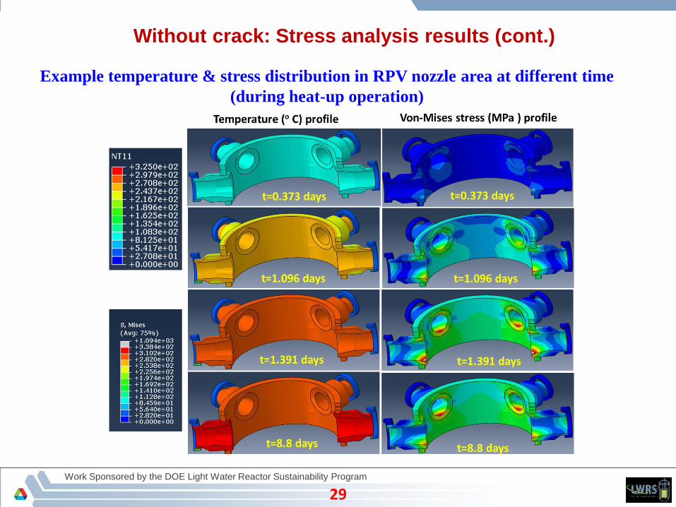
Example temperature & stress distribution in RPV nozzle area at different time
(during heat-up operation)
Without crack: Stress analysis results (cont.)

Work Sponsored by the DOE Light Water Reactor Sustainability Program
3D-FE Thermal-Mechanical Stress Analysis of RPV
and Nozzles under Grid Load-following
(Case-2: With presence of simulated SCC crack)
30
Work Sponsored by the DOE Light Water Reactor Sustainability Program
3131
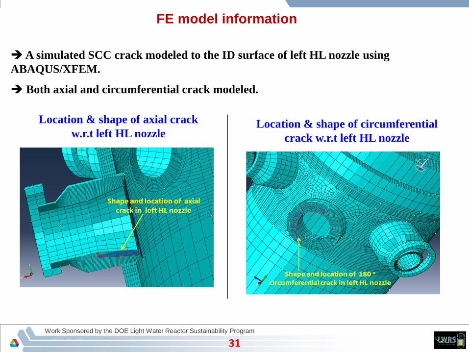
A simulated SCC crack modeled to the ID surface of left HL nozzle using
ABAQUS/XFEM.
Both axial and circumferential crack modeled.
Location & shape of axial crack
w.r.t left HL nozzleLocation & shape of circumferential
crack w.r.t left HL nozzle
FE model information
Work Sponsored by the DOE Light Water Reactor Sustainability Program
3232
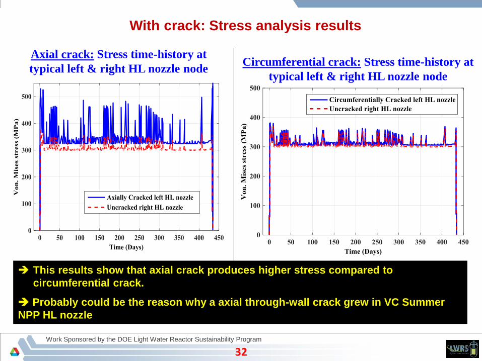
Axial crack: Stress time-history at
typical left & right HL nozzle node
With crack: Stress analysis results
Circumferential crack: Stress time-history at
typical left & right HL nozzle node
This results show that axial crack produces higher stress compared to
circumferential crack.
Probably could be the reason why a axial through-wall crack grew in VC Summer
NPP HL nozzle
Work Sponsored by the DOE Light Water Reactor Sustainability Program
3333
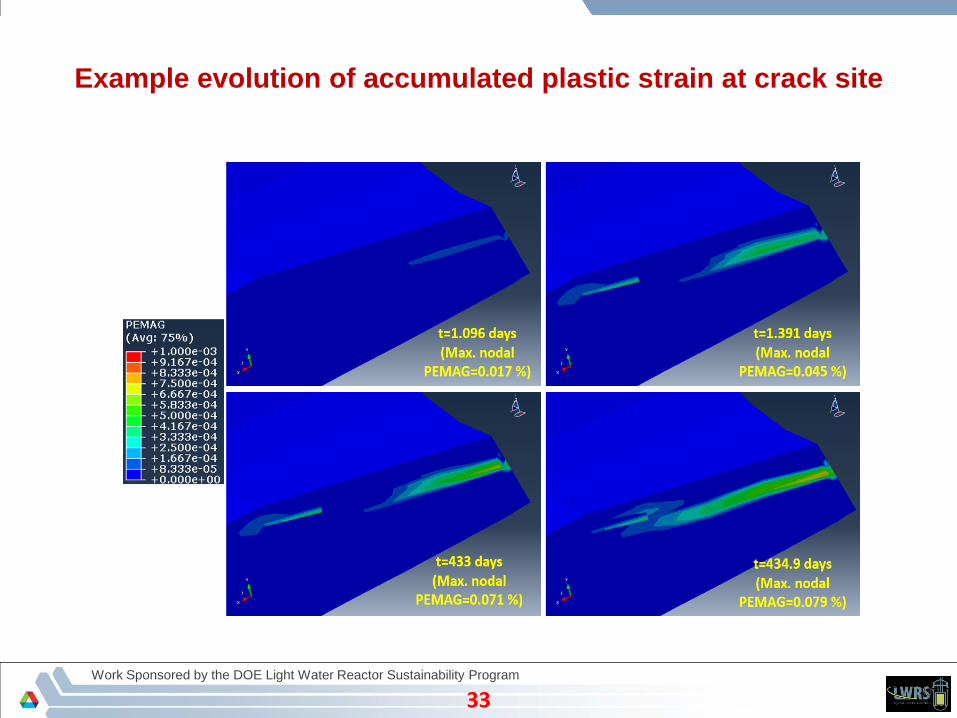
Example evolution of accumulated plastic strain at crack site

Work Sponsored by the DOE Light Water Reactor Sustainability Program
3434
Animation: Stress distribution during heat-up, grid-load following
normal operation & cool-down conditions
(with presence of axial crack in left HL nozzle)
HL nozzle separated
from nozzle support
during heat-up thermal
expansion
HL nozzle crack closing
and opening during grid
load-following power
fluctuation
Snapshot of animation Full animation

Work Sponsored by the DOE Light Water Reactor Sustainability Program
3535
Animation: Imaginary (e.g. loss of coolant accident case) ID pressure
transient (0 – 40 MPa)
(with presence of axial crack in left HL nozzle)
Snapshot of animation Full animation
Crack size at the end of
simulation

Work Sponsored by the DOE Light Water Reactor Sustainability Program
Experiment: Grid Load-Following
(Random Load) Fatigue test
36

Work Sponsored by the DOE Light Water Reactor Sustainability Program
3737
Preliminary experiment: Grid load-following condition
fatigue test (example) resultsExperiment inputs
FE simulated stress scaled along the time axis to finish the test in a reasonable time.
508 LAS specimen tested under in-air and PWR water conditions.
FE results
Scaled PWR water fatigue
test input (as observed)
Observed stroke (1st 25 cycles)
Observed stroke (1st cycle)ANL’s PWR water loop
Initial stress due to
hydrostatic
autoclave pressure

Work Sponsored by the DOE Light Water Reactor Sustainability Program
38
Summary
Variable amplitude fatigue tests under in-air and PWR condition conducted and relevant
martial properties estimated.
1-D analytical model created to check the accuracy of material properties.
3D FE model of test specimen created to check the accuracy of constant amplitude fatigue test
based material properties.
Preliminary 3D FE model created for thermal-mechanical stress analysis of RPV and nozzles
under grid-load following conditions.
Future (FY-17) Research Plan

Work Sponsored by the DOE Light Water Reactor Sustainability Program
39
Some LWRS publications published during FY-16
Mohanty, Subhasish, William Soppet, Saurin Majumdar, and Ken Natesan. Tensile and Fatigue Testing and Material Hardening
Model Development for 508 LAS Base Metal and 316 SS Similar Metal Weld under In-air and PWR Primary Loop Water
Conditions., (September, 2015 ), Argonne National Laboratory, Report No. ANL/LWRS-15/02
(http://www.osti.gov/scitech/biblio/1224989 ).
Mohanty, Subhasish, William K. Soppet, Saurindranath Majumdar, and Krishnamurti Natesan. "Full-scale 3-D finite element
modeling of a two-loop pressurized water reactor for heat transfer, thermal–mechanical cyclic stress analysis, and
environmental fatigue life estimation." Nuclear Engineering and Design 295 (December, 2015): 374-387
(http://www.sciencedirect.com/science/article/pii/S0029549315004641 ).
Mohanty, Subhasish, William Soppet, Saurin Majumdar, and Ken Natesan. Thermal-Mechanical Stress Analysis of PWR
Pressure Vessel and Nozzles under Grid Load-Following Mode: Interim Report on the Effect of Cyclic Hardening Material
Properties and Pre-existing Cracks on Stress Analysis Results., (March, 2016 ), Argonne National Laboratory, Report No.
ANL/LWRS-16/01 (http://www.osti.gov/scitech/biblio/1249554 ).
Mohanty, Subhasish, William K. Soppet, Saurindranath Majumdar, and Krishnamurti Natesan. "In-air and pressurized water
reactor environment fatigue experiments of 316 stainless steel to study the effect of environment on cyclic hardening." Journal
of Nuclear Materials 473 (May, 2016): 290-299 (http://www.sciencedirect.com/science/article/pii/S002231151630037X ).
Mohanty, Subhasish, William K. Soppet, Saurindranath Majumdar, and Krishnamurti Natesan. "Chaboche-based cyclic
material hardening models for 316 SS–316 SS weld under in-air and pressurized water reactor water conditions." Nuclear
Engineering and Design 305 (August, 2016): 524-530 (http://www.sciencedirect.com/science/article/pii/S0029549316301649 ).
Mohanty, Subhasish, Saurin Majumdar, and Ken Natesan. "Steam generator tube rupture simulation using extended finite
element method." Nuclear Engineering and Design 305 (August, 2016): 697-705
(http://www.sciencedirect.com/science/article/pii/S0029549316301923 )

Work Sponsored by the DOE Light Water Reactor Sustainability Program
40
Thank You