environmentally-assisted degradation of nickel-base alloys ... · 1.2 historical overview of...
TRANSCRIPT

ENVIRONMENTALLY-ASSISTEDDEGRADATION OF
NICKEL-BASE ALLOYS IN LWRs

E N V I R O N M E N T A L L Y - A S S I S T E D D E G R A D A T I O N O F N I C K E L - B A S E A L L O Y S I N L W R S
© September 2011
Advanced Nuclear Technology International
Analysvägen 5, SE-435 33 Mölnlycke
Sweden
www.antinternational.com
Environmentally-Assisted Degradation of Nickel-Base Alloys in LWRs
Authors
Peter Scott Noisy Le Roi, France
Pierre Combrade Le Bessat, France
Peter Ford Rexford, New York, USA

E N V I R O N M E N T A L L Y - A S S I S T E D D E G R A D A T I O N O F N I C K E L - B A S E A L L O Y S I N L W R S
Copyright © Advanced Nuclear Technology International Europe AB, ANT International, 2011.
I(V)
Disclaimer
The information presented in this report has been compiled and analysed by
Advanced Nuclear Technology International Europe AB (ANT International®)
and its subcontractors. ANT International has exercised due diligence in this work,
but does not warrant the accuracy or completeness of the information.
ANT International does not assume any responsibility for any consequences
as a result of the use of the information for any party, except a warranty
for reasonable technical skill, which is limited to the amount paid for this Report.
E N V I R O N M E N T A L L Y - A S S I S T E D D E G R A D A T I O N O F N I C K E L - B A S E A L L O Y S I N L W R S
Copyright © Advanced Nuclear Technology International Europe AB, ANT International, 2011.
II(V)
Contents
1 Introduction and background (Peter Scott) 1-1
1.1 Scope of report 1-1 1.2 Historical overview of environmentally-assisted degradation of nickel-base
alloys 1-5
2 Physical metallurgy of nickel-base alloys (Peter Ford) 2-1
2.1 History of development of nickel-base alloys 2-1 2.2 Nickel-base alloys in water cooled nuclear reactors 2-3 2.2.1 Relationship between nickel-base alloys, carbon & low alloy steels, and SSs 2-3 2.2.2 The rationale for the initial choice of nickel-base alloys for use in LWRs 2-7 2.2.3 Wrought nickel-base alloys 2-15 2.2.3.1 Carbide morphologies in Alloy 600 relevant to PWSCC 2-17 2.2.3.2 Carbide morphologies in Alloy 600 relevant to IGA and IGSCC in PWR
secondary systems and in BWRs 2-18 2.2.3.3 Physical metallurgical considerations associated with the replacement of
Alloy 600 with Alloy 690 2-20 2.2.3.4 Metallurgical conditions relevant to sensitization of nickel-base alloys in
BWR service 2-24 2.2.3.5 Cold work 2-25 2.2.4 Nickel alloy weldments 2-26 2.2.4.1 Welding techniques 2-26 2.2.4.2 Nickel-base weld alloy compositions, welding processes and microstructure
development 2-27 2.2.4.3 Interfaces in nickel-base alloy weldments 2-31 2.2.4.4 Weld defects 2-32 2.2.5 Dissimilar metal welds 2-39 2.2.6 Precipitation hardened nickel- base alloys 2-42
3 Corrosion basics of nickel-base alloys (Pierre Combrade) 3-1
3.1 Corrosion potentials in LWR primary circuits 3-1 3.1.1 PWR primary circuit 3-1 3.1.2 PWR secondary circuit 3-2 3.1.3 BWR primary circuit 3-4 3.2 General corrosion 3-8 3.2.1 Thermodynamics 3-8 3.2.2 Surface oxide films 3-16 3.2.2.1 Oxidation in high temperature water 3-16 3.2.2.2 Oxide layers and damage to base metal 3-17 3.2.2.2.1 Oxide layers 3-17 3.2.2.2.2 Damage to base metal 3-21 3.2.2.3 Mechanisms of oxidation 3-24 3.2.2.4 Summary of damage to base metal – grain boundary embrittlement 3-26 3.2.2.5 Oxidation and cation release rates 3-28
4 Laboratory and service experience of SCC of nickel-base alloys in BWRs (Peter Ford) 4-1
4.1 Experience of IGSCC of nickel-base alloys in BWR plant 4-3 4.1.1 Creviced components 4-4 4.1.1.1 Nozzles 4-4 4.1.1.2 Shroud head bolts 4-6 4.1.1.3 Access hole covers 4-7 4.1.2 Uncreviced assemblies 4-8 4.1.2.1 Exposed Alloy 182 4-8 4.1.2.2 Vessel wall attachments 4-9 4.1.2.3 CRD stub tubes 4-10

E N V I R O N M E N T A L L Y - A S S I S T E D D E G R A D A T I O N O F N I C K E L - B A S E A L L O Y S I N L W R S
Copyright © Advanced Nuclear Technology International Europe AB, ANT International, 2011.
III(V)
4.1.2.4 Core support welds 4-11 4.1.3 High strength components 4-12 4.1.3.1 Jet pump beams 4-12 4.1.3.2 Fuel channel fasteners 4-14 4.2 Chronology of SCC development 4-14 4.3 Parametric dependencies for SCC of nickel-base alloys in BWRs 4-18 4.3.1 Tensile stress 4-23 4.3.2 Material 4-29 4.3.3 Corrosion potential and temperature 4-31 4.3.4 Dissolved anions and cations 4-34 4.4 Mechanistic understanding 4-36 4.5 Summary 4-45
5 IGSCC in primary PWR coolant (PWSCC) (Peter Scott) 5-1
5.1 Field experience of PWSCC in Alloy 600 and weld metals 5-1 5.1.1 Alloy 600 SG tubes 5-1 5.1.2 Thick section Alloy 600 components 5-5 5.2 PWSCC of nickel-base weld metals 5-8 5.3 Laboratory studies of PWSCC of Alloy 600 and weld metals 5-11 5.3.1 Hydrogen partial pressure and PWR primary water chemistry 5-13 5.3.2 Temperature 5-16 5.3.3 Stress, crack tip stress intensity and strain rate 5-19 5.3.4 Microstructure of Alloy 600 5-23 5.3.5 Cold work 5-25 5.3.6 Weld composition and microstructure 5-26 5.3.7 Weld residual stress and weld defects 5-28 5.3.8 Influence of weld surface finish 5-29 5.4 Empirical models for Alloy 600 component life prediction 5-32 5.5 Mechanisms of PWSCC of Alloy 600 and weld metals 5-38 5.6 Mitigation of PWSCC in Alloy 600 and weld metals 5-41 5.7 PWSCC of high strength nickel-base alloys 5-43
6 Degradation of Alloy 600 SG tubes in secondary PWR coolant (Pierre Combrade & Peter Scott) 6-1
6.1 Operating experience of IGA/IGSCC 6-4 6.2 Comparison with Alloy 800 operating experience 6-7 6.3 Local environments leading to tube degradation 6-8 6.4 Degradation modes of SG tubes on the secondary side of SGs 6-16 6.4.1 Thinning or wastage 6-16 6.4.2 Denting 6-19 6.4.3 Pitting 6-21 6.4.4 IGA/IGSCC and TGSCC 6-26 6.4.5 Mechanical damage 6-30 6.4.6 Distribution of damage modes in SGs 6-30 6.5 IGA/IGSCC of Alloy 600 – laboratory results 6-31 6.5.1 General trends of IGA/IGSCC in concentrated prototypical environments 6-31 6.5.1.1 IGA/IGSCC subdomains 6-31 6.5.1.2 Effect of environment 6-33 6.5.1.3 Effect of alloy microstructure and composition 6-36 6.5.2 IGA/IGSCC in caustic environments 6-37 6.5.2.1 Potential domains for IGA and IGSCC of Alloy 600 6-39 6.5.2.2 IGA/IGSCC of Alloy 600 MA in pure caustic solutions 6-41 6.5.2.3 Effect of impurities in caustic environments 6-50 6.5.2.4 Mechanism of caustic corrosion of nickel-base Alloys 6-51 6.5.3 IGA/IGSCC in acidic to slightly alkaline sulphate + chloride environments 6-52 6.5.3.1 Effect of environment 6-53 6.5.3.2 Potential domain for IGSCC 6-55 6.5.3.3 Effect of temperature 6-56
E N V I R O N M E N T A L L Y - A S S I S T E D D E G R A D A T I O N O F N I C K E L - B A S E A L L O Y S I N L W R S
Copyright © Advanced Nuclear Technology International Europe AB, ANT International, 2011.
IV(V)
6.5.3.4 Effect of microstructure 6-57 6.5.4 IGA/IGSCC in “complex” near neutral environments 6-58 6.5.5 Corrosion in “contaminated” (“doped”) steam 6-60 6.5.6 Corrosion by low valence sulphur environments 6-60 6.5.6.1 High temperature water 6-61 6.5.6.2 Low temperature water 6-61 6.5.7 Degradation of Alloy 600 in environments containing lead (PbSCC) 6-62 6.5.7.1 Lead species 6-62 6.5.7.2 Lead concentration 6-64 6.5.7.3 Effect of pH 6-65 6.5.7.4 Caustic environments 6-68 6.5.7.5 Acidic to slightly alkaline environments 6-69 6.5.7.6 Mechanism of lead corrosion 6-71 6.5.8 Modelling IGA/IGSCC of Alloy 600 6-72 6.6 Mitigation of secondary side corrosion of SG tubes 6-75 6.6.1 Water chemistry 6-75 6.6.2 SG design 6-76 6.6.3 SG tubes 6-76
7 Alloy 690 and associated weld metals (Peter Scott & Pierre Combrade) 7-1
7.1 Specifications 7-1 7.1.1 SG tubes 7-1 7.1.1.1 Alloy composition 7-1 7.1.1.2 Alloy cleanliness 7-3 7.1.1.3 Alloy microstructure 7-4 7.1.1.4 Mechanical properties 7-4 7.1.1.5 Heat treatments 7-5 7.1.1.6 Surface finish 7-8 7.1.1.7 Cleanliness 7-8 7.1.2 Pressure vessel nozzles 7-9 7.1.2.1 Composition 7-10 7.1.2.2 Alloy microstructure 7-10 7.1.2.3 Mechanical properties 7-11 7.1.2.4 TTs 7-11 7.1.3 Other Alloy 690 thick components 7-12 7.2 Manufacturing 7-12 7.2.1 SG tubes 7-12 7.2.2 SGs 7-13 7.2.3 Pressure vessel nozzles 7-14 7.3 Field experience 7-15 7.4 Laboratory test results 7-15 7.4.1 PWR primary water 7-15 7.4.1.1 Experimental studies of Alloy 690 TT 7-16 7.4.1.2 Improvement factors for Alloy 690 TT relative to Alloy 600 7-24 7.4.1.3 Fatigue and corrosion fatigue 7-25 7.4.2 PWR secondary side of SG tubes 7-26 7.4.2.1 Caustic environments 7-27 7.4.2.2 Acidic to slightly alkaline sulphate + chloride environments 7-32 7.4.2.3 Complex near-neutral environments 7-33 7.4.2.4 “Doped” steam 7-33 7.4.2.5 Low valence sulphur environments 7-33 7.4.2.6 Lead containing environments 7-33 7.4.2.7 Improvement factors for Alloy 690 TT relative to Alloy 600 7-37

E N V I R O N M E N T A L L Y - A S S I S T E D D E G R A D A T I O N O F N I C K E L - B A S E A L L O Y S I N L W R S
Copyright © Advanced Nuclear Technology International Europe AB, ANT International, 2011.
V(V)
8 LTCP (Peter Scott) 8-1
9 Impact of degradation of Nickel-Base Alloys on LWR water chemistries (Pierre Combrade) 9-1
9.1 PWR primary system chemistry guidelines and corrosion control 9-1 9.2 PWR secondary system chemistry guidelines and corrosion control 9-3 9.3 BWR reactor coolant system chemistry guidelines and corrosion control 9-5
10 References 10-1
Nomenclature
Unit conversion

E N V I R O N M E N T A L L Y - A S S I S T E D D E G R A D A T I O N O F N I C K E L - B A S E A L L O Y S I N L W R S
Copyright © Advanced Nuclear Technology International Europe AB, ANT International, 2011.
1-1(1-7)=
1 Introduction and background (Peter Scott)
1.1 Scope of report This report is the fourth in a series devoted to environmentally induced or assisted degradation of structural materials in Light Water Reactors (LWRs) and in this instance is devoted to nickel-based alloys. These alloys are used extensively in Pressurized Water Reactors (PWRs) and to a lesser extent in Boiling Water Reactors (BWRs). Like Stainless Steels (SSs), they are chosen for components exposed to the primary reactor coolants for their strength and corrosion resistance at temperatures up to about 345°C. However, due to the cost of nickel-base alloys relative to SSs, the former are only chosen where specific circumstances dictate that no SS alternative is suitable.
Three broad categories of use of nickel-base alloys can be identified:
as interface materials between Carbon and Low Alloy Steels (C&LAS) and SSs;
as corrosion resistant Steam Generator (SG) tubing in PWRs;
as high strength fasteners and springs immersed in LWR coolants.
In the first category, there are many different types of nozzles or attachments to major C&LAS pressure vessels of both PWRs and BWRs. The main advantage from a design perspective is the value of the coefficient of thermal expansion that is typically intermediate between that of C&LAS and of austenitic SSs (Table 1-1), thus minimizing the thermal stresses developed both during welding and during heating to or cooling down from the operating temperature. The locations of these attachments to C&LAS components that are usually fabricated from wrought Alloy 600 or Alloy 690 and their weld metal equivalents are shown for PWRs in Figure 1-1 and for BWRs in Figure 1-2.
Table 1-1: Thermal conductivity and thermal expansion coefficient of Alloys 600 and 690 compared to Alloy 800, austenitic SS and low alloy steel.
Alloy 600 690 800 Type 304L
SS Low Alloy Steel
Thermal conductivity at 300°C (W/m. °C) 19.0 17.3 16.3 20
Thermal expansion from RT to 300°C (µm/m.°C) 14.2 14.5 16.2 17.5 ~ 12 to 13
The generic compositions and minimum yield strengths of these nickel-base alloys are given in Table 1-2 where it can be seen that the main difference between Alloy 600 and Alloy 690 is the increased chromium content from 14-17% to 28-31%. The metallurgical characteristics of these fully austenitic materials and their optimization in terms of metallurgical structure over the years are described here in Section 2 together with the characteristics of nickel-base dissimilar metal welds. Their general corrosion and cation release rates (of particular importance to minimizing radiation fields from activated corrosion products) are reviewed in Section 3. Experience with Stress Corrosion Cracking (SCC) of Alloy 600 and its compatible weld metals Alloys 132, 182 (for Shielded Metal Arc Welding (SMAW)) and 82 (for automatic gas tungsten arc and submerged arc welding) in the primary reactor coolants is described for BWRs in Section 4 and for PWRs in Section 5.

E N V I R O N M E N T A L L Y - A S S I S T E D D E G R A D A T I O N O F N I C K E L - B A S E A L L O Y S I N L W R S
Copyright © Advanced Nuclear Technology International Europe AB, ANT International, 2011.
1-2(1-7)=
Figure 1-1: Typical locations in PWR primary circuits where nickel-base Alloys 600 or 690 and the corresponding weld metals Alloys 182, 82 or Alloys 152, 52 are used.
Figure 1-2: Typical locations in BWR primary coolant circuits where nickel-base Alloys 600 and X750 and the weld metals Alloys 182, 82 are used.

E N V I R O N M E N T A L L Y - A S S I S T E D D E G R A D A T I O N O F N I C K E L - B A S E A L L O Y S I N L W R S
Copyright © Advanced Nuclear Technology International Europe AB, ANT International, 2011.
1-3(1-7)=
Table 1-2: Some composition and minimum yield strength specifications for wrought and Mill Annealed (MA) Nickel-base alloys and Alloy 800 used in LWRs1.
Alloy 600 Alloy 132 Alloy 182 Alloy 82 Alloy 690 Alloy 152 Alloy 52 Alloy 800
Nickel >72.0 >68.0 Bal. Bal. >58.0 Bal. Bal. 30-35
Chromium 14-17 13-17 13-17 18-22 28-31 28-31.5 28-31.5 19-23
Iron 6-10 <11 ≤10.0 ≤3.00 7-11 8-12 8-12 >39.5
Titanium ≤1.0 ≤0.75 ≤0.50 ≤1.0 0.15-0.60
Aluminium ≤1.10 0.15-0.60
Niobium plus Tantalum 1.5-4.0 1.0-2.5 2.0-3.0 1.2-2.2 ≤0.10
Molybdenum ≤0.50 ≤0.05
Carbon ≤0.05 <0.08 ≤0.10 ≤0.10 ≤0.04 ≤0.045 ≤0.040 ≤0.10
Manganese ≤1.0 2.0-3.5 5.0-9.5 2.5-3.5 ≤0.50 ≤5.0 ≤1.0 ≤1.50
Sulphur ≤0.015 <0.015 ≤0.015 ≤0.015 ≤0.015 ≤0.008 ≤0.008 ≤0.03
Phosphorus <0.015 ≤0.030 ≤0.030 ≤0.020 ≤0.020 ≤0.03
Si l icon ≤0.5 <0.5 ≤1.0 ≤0.50 ≤0.50 ≤0.65 ≤0.50 ≤1.0
Copper ≤0.5 <0.5 ≤0.50 ≤0.50 ≤0.5 ≤0.50 ≤0.30 ≤0.75
Cobalt ≤0.10 ≤0.12 ≤0.10 ≤0.10 ≤0.020 ≤0.020
Yield strength MPa >240 >240 >207
Modified from the original by A.N.T. International, 2011
1 Note that these are generic specifications for these alloy types that are usually more tightly specified within the ranges shown for nuclear plant applications by vendors, utilities or regulatory authorities.

E N V I R O N M E N T A L L Y - A S S I S T E D D E G R A D A T I O N O F N I C K E L - B A S E A L L O Y S I N L W R S
Copyright © Advanced Nuclear Technology International Europe AB, ANT International, 2011.
2-1(2-43)=
2 Physical metallurgy of nickel-base alloys (Peter Ford)
This is a broad subject covering a wide range of nickel-base alloys used in a variety of environments encountered in the chemical processing, power generation (fossil and nuclear) and aerospace industries. A full coverage of the topic would necessarily address the development, fabrication and properties of nickel-base alloys that range from commercially pure nickel to those alloys that are strengthened by either solid solution alloying additions or by second phase precipitation effects. At the end of the spectrum are the specialty alloys that include the “superalloys”, which meet the high temperature creep and fatigue resistance needed for aircraft engine applications.
Such a broad coverage is inappropriate for this report. Thus, following a brief historical perspective of nickel alloy development in general, attention is focused on the physical metallurgy of nickel-base alloys used in LWRs, (Figure 1-1 and Figure 1-2), (Table 1-1 and Table 1-3). This focus covers three topics.
First, the broad physical metallurgical inter-relationships between the main structural material classes, (ferritic and low alloy steels, SSs and nickel-base alloys), are discussed. The reason for such a discussion is to give continuity with similar physical metallurgical discussions in earlier ANT International reports addressing materials degradation [Ford & Scott, 2008], [Ford et al, 2010], and also to emphasize that, with the use of nickel-base alloys for dissimilar metal welds, there is a melding of the physical metallurgical properties in and adjacent to the fusion line.
Second, the rationale for the initial choice of nickel-base alloys in LWRs that was based on their mechanical and physical metallurgical properties is addressed in the light of the original, and the subsequent “unexpected”, concerns regarding environmentally-assisted degradation.
Finally, more detailed attention is given to the physical metallurgical attributes of the three nickel-alloy product types used in PWRs and BWRs; namely, (a) wrought alloys used in various pressure boundary components such as safe ends and tubing, (b) weldments used to join nickel-base alloys, or when joining dissimilar alloys (such as low alloy ferritic alloys to SSs), and (c) high strength alloys used in bolts, springs, jet pump beams, etc. in core internals and fuel assemblies.
The impact of these physical metallurgical properties on general corrosion, IGA, SCC of nickel-base alloys in BWRs, and in both the primary and secondary systems in PWRs, is addressed in later Sections.
2.1 History of development of nickel-base alloys Nickel-base alloys have been developed since the early 1900's because of both their high ductility and fracture resistance, and their high corrosion resistance over a wide range of acidic and alkaline environments. This latter attribute is due, as will be discussed in Section 3, to the stability of nickel in water in reducing environments and the presence of various low solubility oxide surface films in more oxidizing environments.
In addition to these basic mechanical and electrochemical attributes, nickel is able to hold in solid solution significant amounts of various alloying elements (Cu, Cr, Mo, Fe, W), thereby opening up the development of solid solution strengthened alloys with enhanced corrosion resistance in a number of challenging environments. Other alloying elements, such as Ti, Al and/or Nb may confer strengthening via precipitation hardening. A nickel alloy “family tree” (Figure 2-1) illustrates the logical development of the wrought solid-solution strengthened alloys (denoted by the shaded boxes) and the transition to the precipitation hardened alloys.

E N V I R O N M E N T A L L Y - A S S I S T E D D E G R A D A T I O N O F N I C K E L - B A S E A L L O Y S I N L W R S
Copyright © Advanced Nuclear Technology International Europe AB, ANT International, 2011.
2-2(2-43)=
Figure 2-1: “Family tree” for nickel and its alloys.
The “family tree” in this example starts with commercially pure nickel (Alloy 200). The initial alloying element addition was copper to produce the nickel-copper alloy, MonelTM (Alloy 400) in 1906; this was facilitated by the similarity between the composition of the alloy (Ni-30%Cu) and the “matte” produced during the extraction process from the ore. This alloy exhibited excellent corrosion resistance in seawater and more aggressive environments such as fluoride salts used in UO2 processing, and was widely used in high pressure feed water heaters for fossil fired power stations. The addition of Al and Ti (typically 2.3-3.15% Al and 0.35-0.85% Ti) imparted a marked increase in strength due to precipitation hardening, and the resultant commercial alloy K-MonelTM (Alloy K500) has found use in marine environments for fasteners, propeller shafts, etc. However, apart from some isolated use in feed water heaters for LWRs, its use in primary coolant environments has not been widespread due to the danger of copper contamination and ensuing Crud-Induced Localized Corrosion (CILC) of zirconium alloy fuel cladding.
A range of nickel-base alloys was developed primarily for the chemical industry in the time period 1921-1964 under trade names such as Hastelloy (A, B, C, D, F, G), and Incoloy (800, 825). This initial generation of Ni-base alloys also included Inconel 600 (introduced in 1931), which was highly resistant to SCC in chloride environments. This alloy acted as a basis for later generations of alloys with specialty usage in, for example, acetic acid production (Ni-Mo alloys), phosphoric acid evaporators (Ni-Cr-Fe-Mo alloys), and flue gas scrubbers (Ni-Cr-Mo alloys).
These developments led to the use of Alloy 600 in LWRs in the 1960s and 1970s, which, in turn, were the basis for the subsequent wrought Alloy 690 and associated weld alloys. These particular developments and the physical metallurgy of these alloys will be discussed in detail in Sections 2.2.3 and 2.2.4).

E N V I R O N M E N T A L L Y - A S S I S T E D D E G R A D A T I O N O F N I C K E L - B A S E A L L O Y S I N L W R S
Copyright © Advanced Nuclear Technology International Europe AB, ANT International, 2011.
2-3(2-43)=
Alloying Alloy 600 with further additions of Ti, Al and/or Nb led to the development of the precipitation hardened Alloy X-750, while a further addition of Mo (plus some substitution of nickel with iron) led to the Alloy 718. The most common of these precipitation hardening phases are gamma prime (γ'Ni3Al, Ni3Ti and Ni3(Ti,Al)) utilized in Alloy X-750 and gamma double prime (γ''-Ni3Nb) used in Alloy 718. These latter developments for the LWR industry will be discussed in Section 2.2.6. It should be pointed out in this historical context that lessons-learned were available from the developments of precipitation hardened “superalloys” for the aeronautical industry that were later combined with oxide dispersion hardening approaches. The latter were required to satisfy the demand for a combination of high temperature strength and creep resistance with oxidation resistance needed for gas-turbine aircraft engines.
During the late 1940s and early 1950s, nickel was declared a strategic material in the USA (because of the Korean War) and its overall usage in nickel-base alloys was reduced by substituting some of the nickel content with iron. Indeed, alloys introduced in this time period by the International Nickel Company (INCO) and Haynes, such as Incoloy 800 (Fe-32%Ni-20% Cr), Incoloy 825 (Ni-22%Cr-32%Fe-2%Cu-2%Mo) and Hasteloy G (Ni-22%Cr-18%Fe-6.5%Mo-2%Nb-2%Cu), were not strictly “Ni-base” alloys. However, because of its good corrosion resistance and lack of stress corrosion susceptibility in PWR primary environments, Alloy 800 was adopted by Atomic Energy of Canada Limited (AECL) and KWU2-Siemens as the tubing alloy for, respectively, their Canadian Deuterium Uranium (CANDU) and PWR SGs. The reported operating experience has been excellent for reasons discussed in Sections 5, 6 and 7.
In the same time frame of the first half of the 20th century, there were processing developments for nickel-base alloys (as well as for SSs) which facilitated their commercial production. These ranged from Air Induction Melting (AIM) to combinations of Vacuum Induction Melting (VIM), ElectroSlag Remelting (ESR) and Vacuum Arc Remelting (VAR). The objective of these processes was to control both the impurity levels and, coupled with the Argon-Oxygen-Decarburization (AOD) process, the carbon content without having excessive chromium loss due to oxidation.
2.2 Nickel-base alloys in water cooled nuclear reactors
2.2.1 Relationship between nickel-base alloys, carbon & low alloy steels, and SSs
There is a range of structural alloys used in water-cooled nuclear reactors which, as indicated in the ternary equilibrium diagram for the nickel-chromium-iron system at 400°C (Figure 2-2), form a spectrum of compositions. The ferritic alloys, such as the carbon and low alloy steels and the high strength SSs (17-4PH, A410) are found at the iron-rich end of the diagram. Then, as the nickel content increases, to the cast and wrought SSs (CFX, 3XX) leading to alloys, such as Alloy 600 and its cousins, Alloys 182, 132, 82, 690, 152, 52, 52M, X-750 and 718 at the nickel-rich end of the diagram. As might be expected, there is an associated spectrum of physical metallurgical phenomena, such as the stability of equilibrium phases, tensile properties and fracture resistance, in traversing from the iron-rich to the nickel-rich ends of this equilibrium diagram. This is important to recognize since the nickel-base alloys are often used as welds to join dissimilar metals such as the ferritic carbon and low alloy steels and austenitic SSs, and a transition between these physical properties will occur in the dilution zone at the weld fusion line.
2 KraftwerkUnion

E N V I R O N M E N T A L L Y - A S S I S T E D D E G R A D A T I O N O F N I C K E L - B A S E A L L O Y S I N L W R S
Copyright © Advanced Nuclear Technology International Europe AB, ANT International, 2011.
3-1(3-39)=
3 Corrosion basics of nickel-base alloys (Pierre Combrade)
3.1 Corrosion potentials in LWR primary circuits The corrosion potentials of Ni-base Alloys in LWRs primary circuits are mainly determined by the nature and concentrations of oxidising and/or reducing species (principally hydrogen), the water flow rate and the temperature. The state of the surface (oxidized, freshly machined, etc.) may also affect the corrosion potential to some extent. In the same environment, with similar surface conditions, corrosion potentials of Ni-base Alloys and SSs are identical. There are few studies specifically devoted to the determining corrosion potentials of Ni-base Alloys and most of the following description uses data obtained on Type 3xx SSs.
3.1.1 PWR primary circuit
In PWR primary circuits, i.e. in a practically fully de-aerated environment and in the presence of dissolved hydrogen, it has long been known that many materials including Ni-base alloys and SSs behave as hydrogen redox electrodes rather than as a corrosion electrode (Figure 3-1) [Indig & Groot, 1969] and [Szklarska-Smialowska et al, 1991]. This is because the exchange current density of the H+/H2 reaction in high temperature, hydrogenated water (several μA/cm2 at ~300°C according to [Cowan & Kaznoff, 1973]) is much higher (by more than an order of magnitude) than the oxidation current density of stainless materials (Figure 3-2).
Figure 3-1: Corrosion potential of Type 304 SS in lithiated, hydrogenated water compared to the Reversible Hydrogen Electrode (RHE) potential as a function of temperature. Modified after [Szklarska-Smialowska et al, 1991].

E N V I R O N M E N T A L L Y - A S S I S T E D D E G R A D A T I O N O F N I C K E L - B A S E A L L O Y S I N L W R S
Copyright © Advanced Nuclear Technology International Europe AB, ANT International, 2011.
3-2(3-39)=
Figure 3-2: Evans diagram showing how the corrosion potential of SS in PWR primary water is almost equal to the RHE potential because the exchange current density of the H+/H2 reaction is much higher than the oxidation current density of SS.
This has the following consequences:
Currents measured at the corrosion potential by linear polarisation techniques are mainly representative of the H+/H2 reaction rather than oxidation of SS or a nickel-base alloy;
Knowing the hydrogen content of the environment is sufficient to be able to calculate the corrosion potential versus the RHE, (which is the potential versus the H+/H2 equilibrium at the pH and temperature of the environment for a partial pressure of hydrogen of 1 bar) with an accuracy of few mV without any direct measurement. If the pH at temperature is also known, the corrosion potential can be calculated versus the Standard Hydrogen Electrode (SHE) at temperature.
3.1.2 PWR secondary circuit
PWR secondary side water is deaerated and contains an oxygen scavenger (hydrazine) in order to obtain a corrosion potential as low as possible. However, the hydrogen content of the secondary water is quite low (typically a few ppb since it is preferentially stripped into the steam phase) and the H+/H2 equilibrium does not always control the corrosion potential.
Accordingly, the corrosion potential is not as low as in PWR primary water (even on the RHE scale). It is more sensitive to hydrodynamic conditions than the corrosion potential in PWR primary water and it depends on the chemistry of each plant. Several sets of measurements have been performed in experiments simulating feedwater lines [Pein et al, 2000]. Measurements have also been made in actual feedwater lines in PWRs [Kassen et al, 1994] and CANDUs [Brett et al, 1996], in the hot and cold legs of Voda Voda Energo Reactor (VVER) SGs [Makelä et al, 1996], and even near the tubesheet of the German Biblis plant equipped with Alloy 800 tube bundles [Beyer et al, 1988], [Stellwag & Kilian, 1992]. The results show that corrosion potentials of Pt and Alloy 600 can vary from ~-200 to ~-600 mV/SHE depending on the environmental conditions, which means that the stable iron oxides may be haematite (at higher potentials) or magnetite (at lower potentials) (see Figure 3-9).

E N V I R O N M E N T A L L Y - A S S I S T E D D E G R A D A T I O N O F N I C K E L - B A S E A L L O Y S I N L W R S
Copyright © Advanced Nuclear Technology International Europe AB, ANT International, 2011.
3-3(3-39)=
In fact, the corrosion potential of Alloy 600 or Alloy 800 SG tubes exhibits a strong dependence on the hydrazine/oxygen ratio in PWR secondary feedwater, as shown in Figure 3-3.
Figure 3-3: Correlation between the hydrazine/oxygen ratio in secondary feedwater and the corrosion potential of tube materials.
However, increasing hydrazine at levels above 100 to 200 μg/kg does not bring any significant further reduction in corrosion potential (Figure 3-4).

E N V I R O N M E N T A L L Y - A S S I S T E D D E G R A D A T I O N O F N I C K E L - B A S E A L L O Y S I N L W R S
Copyright © Advanced Nuclear Technology International Europe AB, ANT International, 2011.
4-1(4-46)=
4 Laboratory and service experience of SCC of nickel-base alloys in BWRs (Peter Ford)
As discussed in Section 1 and Section 2, nickel-base alloys have a number of desirable electrochemical and physical properties as structural materials in LWRs. As a result, Alloys 600, X-750, 182 and 82 have been used widely in BWR components, as indicated in Table 4-1 and schematically in Figure 4-1. Alloy 690 has also been used in BWRs as a replacement material for Alloy 600. The specific designs of the reactor components for which nickel-base alloys are used have evolved over the years depending on the reactor designer. For instance, the number of pressure vessel penetrations has increased markedly with evolutions in the Emergency Core Cooling System (ECCS), CRD and instrumentation systems. Thus, the number of dissimilar metal penetrations through the pressure vessel wall, which in large part rely on nickel-base alloys, have increased as the designs have progressed from the GE BWR-2 to BWR-6, for example.
Table 4-1: BWR components fabricated out of Nickel-base alloys.
Safe Ends Alloy 600 / 182 / 82
Shroud Head Bolts Alloy 600
Control Rod Penetrations Alloy 600/182/82
Instrumentation Penetrations Alloy 600/182/82
Access Hole Covers Alloy 600/182
Pressure Vessel Attachment Pads Alloy 182
Core Shroud Support Alloy 600/182/82
Pressure Vessel Nozzle Welds Alloy 82/182
Jet Pump Beams X-750
Fuel Rod Spacers X-750
Modified from the original by A.N.T. International, 2011
Various degradation modes are possible in nickel-base alloys in BWRs, including corrosion fatigue, and IASCC for high-strength alloys used in fuel assemblies, but the most prevalent is IGSCC. This predominant cracking mode has been reproduced in the laboratory for wrought alloys (Figure 4-2a), weldments 27 (Figure 4-2b) and precipitation-hardened alloys (Figure 4-2c). In all cases, it has been demonstrated that the cracking sensitivity is a function of interacting parameters such as the presence of crevices, the oxidizing effect of dissolved O2 and H2O2, the presence of anionic impurities, especially SO4
2- and Cl-, tensile stress, and the composition and microstructure of the alloy.
27 Note that the cracking morphology for the weld alloys has often been classified as IDSCC and although (as discussed in Section 2.2.4.3) this may be correct if the solidification grain boundaries(SGB) have been pinned by, e.g. NbC, in the last material to solidify, in most cases the SGB will have migrated from that position. Thus, the more correct term is IGSCC.

E N V I R O N M E N T A L L Y - A S S I S T E D D E G R A D A T I O N O F N I C K E L - B A S E A L L O Y S I N L W R S
Copyright © Advanced Nuclear Technology International Europe AB, ANT International, 2011.
4-2(4-46)=
Figure 4-1: Schematic of BWR pressure vessel and internals indicating those structures utilizing nickel-base alloys.
The objective of this Section is to report and comment on the system parameters, (material composition and microstructure, stress, environment), that control the extent of SCC of nickel-base alloys in BWRs. Such an understanding forms the basis of a life prediction methodology that is central to an effective mitigation strategy. Consequently, this Section is organized around the following sequence of sub-sections:
“Plant Experience of IGSCC”, (Section 4.1) since this defines the practical problem and is the ultimate data base that has to be predicted.
“Chronology of SCC”, (Section 4.2) since the observation of a macroscopic crack in a component is preceded by a number of physical events associated with “crack initiation” and “crack propagation”.
“Parametric Dependencies for Nickel-base Alloys in BWR Environments”, (Section 4.3) since it is the primary and secondary interactions between the relevant material, stress and environment parameters that control the extent of SCC susceptibility.
“Mechanistic Understanding”, (Section 4.4). This topic is included since it is unlikely that an understanding of plant experience alone and the parametric dependencies in Sections 4.1 and 4.3 will, lead to a comprehensive life prediction capability. Based on experience in managing SCC in SSs [Ford et al, 2010] and low-alloy steels [Ford & Scott, 2008], a quantitative understanding of the mechanism of cracking can give a broader basis for predicting future cracking events.
“Summary” (Section 4.5).

E N V I R O N M E N T A L L Y - A S S I S T E D D E G R A D A T I O N O F N I C K E L - B A S E A L L O Y S I N L W R S
Copyright © Advanced Nuclear Technology International Europe AB, ANT International, 2011.
4-3(4-46)=
Figure 4-2: Stress corrosion cracks in oxygenated 288°C water for (a) Alloy 600, (b) Alloy 182 and (c) Alloy X750 [Andresen et al, 2005].
4.1 Experience of IGSCC of nickel-base alloys in BWR plant
The phenomenology of IGSCC of nickel-base alloys in either the laboratory or in operating BWRs is similar to that of austenitic SSs in terms of the cracking dependency on the degree of grain boundary sensitization (Section 2), water chemistry and tensile stress. The incidence of cracking of nickel-base alloys in BWRs has, however, been relatively less than that for the SSs, being confined to Alloys 600, 182 and X750, under varying (depending on the alloy) conditions of geometry (e.g. crevices), water chemistry, localized stress, temperature and cold work. Although IGSCC can be initiated in laboratory tests in the higher Cr content alloys, such as Alloy 82, there have been no occurrences of IGSCC in BWRs operating under the water chemistry guidelines recommended by EPRI. Indeed, in 1988, the United States Nuclear Regulatory Commission (USNRC) issued a statement [NRC28, 1988b] based on plant experience that “Inconel 82 is the only commonly used nickel-base weld alloy (in BWRs) considered to be resistant (to SCC)”.
The main incidents of IGSCC in operating BWRs for Alloys 600, X750 and 182 are now discussed under the categories of “creviced”, “uncreviced” and “high strength” components.
28 Nuclear Regulatory Commission
E N V I R O N M E N T A L L Y - A S S I S T E D D E G R A D A T I O N O F N I C K E L - B A S E A L L O Y S I N L W R S
Copyright © Advanced Nuclear Technology International Europe AB, ANT International, 2011.
5-1(5-46)=
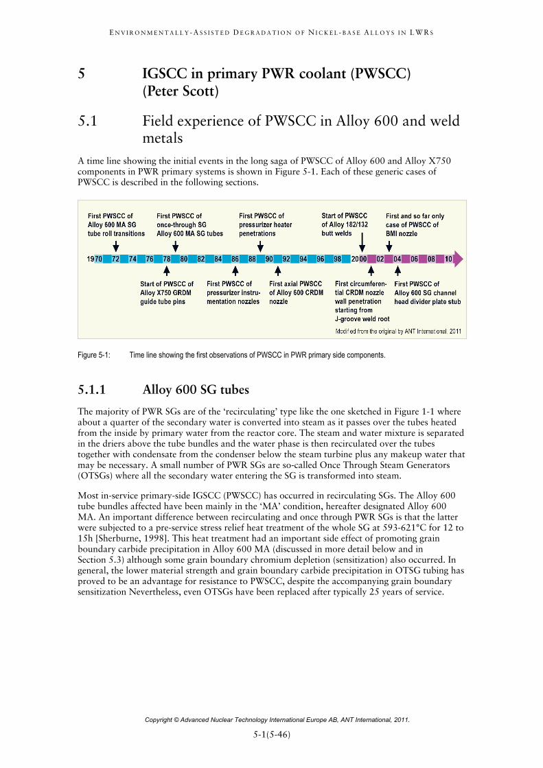
5 IGSCC in primary PWR coolant (PWSCC) (Peter Scott)
5.1 Field experience of PWSCC in Alloy 600 and weld metals
A time line showing the initial events in the long saga of PWSCC of Alloy 600 and Alloy X750 components in PWR primary systems is shown in Figure 5-1. Each of these generic cases of PWSCC is described in the following sections.
Figure 5-1: Time line showing the first observations of PWSCC in PWR primary side components.
5.1.1 Alloy 600 SG tubes
The majority of PWR SGs are of the ‘recirculating’ type like the one sketched in Figure 1-1 where about a quarter of the secondary water is converted into steam as it passes over the tubes heated from the inside by primary water from the reactor core. The steam and water mixture is separated in the driers above the tube bundles and the water phase is then recirculated over the tubes together with condensate from the condenser below the steam turbine plus any makeup water that may be necessary. A small number of PWR SGs are so-called Once Through Steam Generators (OTSGs) where all the secondary water entering the SG is transformed into steam.
Most in-service primary-side IGSCC (PWSCC) has occurred in recirculating SGs. The Alloy 600 tube bundles affected have been mainly in the ‘MA’ condition, hereafter designated Alloy 600 MA. An important difference between recirculating and once through PWR SGs is that the latter were subjected to a pre-service stress relief heat treatment of the whole SG at 593-621°C for 12 to 15h [Sherburne, 1998]. This heat treatment had an important side effect of promoting grain boundary carbide precipitation in Alloy 600 MA (discussed in more detail below and in Section 5.3) although some grain boundary chromium depletion (sensitization) also occurred. In general, the lower material strength and grain boundary carbide precipitation in OTSG tubing has proved to be an advantage for resistance to PWSCC, despite the accompanying grain boundary sensitization Nevertheless, even OTSGs have been replaced after typically 25 years of service.

E N V I R O N M E N T A L L Y - A S S I S T E D D E G R A D A T I O N O F N I C K E L - B A S E A L L O Y S I N L W R S
Copyright © Advanced Nuclear Technology International Europe AB, ANT International, 2011.
5-2(5-46)=
PWSCC of Alloy 600 SG tubing evolved from a laboratory prediction during the 1950s and ‘60s to a major in-service degradation mechanism from the 1970s onwards. In 1971, the first confirmed primary-side cracking of hot leg roll transition regions at the tube sheet and in tight first row U-bends of recirculating SGs occurred [Schenk, 1976]. Leakage at U-bends was experienced in the Obrigheim SGs after only 2 years of operation. From the mid-1980s to the present day, cracking of Alloy 600MA tubes from the primary side became a significant generic problem [Diercks et al, 1999], [Buisine et al, 2010]. Cracking, mainly axial but occasionally circumferential, has occurred both in the tight U-bends on the inner two rows at the apex and at the tangent points with the straight sections, and also close to the tube sheet surface at the transition expansion or roll expansion regions of recirculating SGs, as indicated in Figure 5-2. Additionally, denting of SG tubes at intersections with drilled carbon steel support plates (see Section 6) caused by excessive corrosion of the carbon steel within the secondary side crevices has also caused PWSCC to initiate and grow on the inside of tubes deformed in this way.
Figure 5-2: PWR Primary Side Steam Generator Tube Cracking (PWSCC).
Roll transition cracking has been responsible for premature SG replacement at many plants. This has been especially the case in France where a two-step mechanical kiss roll was adopted in the early 1980s at the transition between the expanded tubes in the tube sheet and the free span above the tube sheet, a feature that lowered residual stresses on the secondary side but resulted in high residual stresses on the primary side. Towards the end of the 1980s hydraulic expansion of tubes in the tube sheet was developed, which greatly reduced residual stresses in the diameter transition zone, and continues to be used to this day for replacement generators with Alloy 690 tube bundles.

E N V I R O N M E N T A L L Y - A S S I S T E D D E G R A D A T I O N O F N I C K E L - B A S E A L L O Y S I N L W R S
Copyright © Advanced Nuclear Technology International Europe AB, ANT International, 2011.
5-3(5-46)=
The first roll transitions experiencing IGSCC were located on the hot leg side where the temperature is typically around 320°C (610°F) and is 30 to 40°C (55 to 70°F) hotter than the cold leg inlet at 280°C (535°F). Thus, it was clear that temperature had a significant influence on PWSCC initiation, indicating a thermally activated process whose temperature dependence could be fitted to the Arrhenius equation. The apparent activation energy so derived is rather high at ~180 kJ/mole so that a typical temperature difference of 30°C (55°F) between the hot and cold legs could easily account for a factor of four to five difference in the time to the onset of detectable cracking. Consequently, reduction in primary water temperature is a possible mitigation action to reduce PWSCC damage (Section 5.6).
The magnitude of the tensile stresses, particularly residual stress from fabrication, also has a major impact on the initiation time for PWSCC. Thus, only the most highly strained regions of SG tubing (that is, row-one and two U-bends, roll transition regions, expanded regions, and dented areas) have exhibited IGSCC. Techniques for in situ mitigation of these high residual stresses have been developed (Section 5.6).
Material susceptibility to PWSCC, in combination with the environmental and residual stress factors mentioned above, is also a major factor affecting the occurrence of cracking in service. Most PWSCC has occurred in MA tubing. Initially, a so-called low temperature mill anneal at around 980°C was used to optimize the mechanical properties but this variant of Alloy 600 MA proved to be highly susceptible to PWSCC in service [Diercks et al, 1999]. Later, at around the same time as improved fabrication processes were being introduced to reduce residual stresses, a so-called high temperature mill anneal at ~1050°C was introduced for Alloy 600 and which on average proved to be somewhat less susceptible in service.
There is, nevertheless, considerable underlying variability in susceptibility of Alloy 600 MA tubing to PWSCC independent of the mill anneal temperature. Some mill-annealed tubing has not experienced any PWSCC over extended periods of operation but in many other cases it has occurred in as little as 1 to 2 years of service, particularly at roll transitions. This variability of PWSCC response is even seen between heats from the same manufacturer in the same SG, as shown in Figure 5-3 [Scott, 2000]. The data in this figure on PWSCC susceptibility of different heats of Alloy 600 can be fitted to a lognormal distribution. Thus, a rather small fraction of highly susceptible Alloy 600MA heats may be responsible for a disproportionately high number of tubes affected by PWSCC. The reasons for such variability are only partly understood but carbide morphology is one important influencing parameter (see below and Section 5.3.4). Other factors are the surface finish on the primary side and include the inadvertent presence of residues of tube drawing lubricants, surface roughness, and the composition of the bright annealing gas used during mill annealing; only hydrogen with a controlled low dew point of less than - 40°C is now acceptable.

E N V I R O N M E N T A L L Y - A S S I S T E D D E G R A D A T I O N O F N I C K E L - B A S E A L L O Y S I N L W R S
Copyright © Advanced Nuclear Technology International Europe AB, ANT International, 2011.
6-1(6-77)=
6 Degradation of Alloy 600 SG tubes in secondary PWR coolant (Pierre Combrade & Peter Scott)
Degradation of SG tubing from the secondary side of PWR SGs has been reviewed on several occasions for ANT International mainly from the perspective of chemists who manage the secondary water chemistry [Riess et al, 2007], [Riess et al, 2009], [Odar & Nordmann, 2010]. The materials perspective on this issue has also been summarized for ANT International [Riess et al, 2007] as well as being reviewed in some considerable detail a few years ago in the open technical literature [Staehle & Gorman, 2003 and 2004a&b]. The present review of secondary side degradation of PWR SG tubing concentrates on the material factors. It summarizes the main parametric trends arising from the previously cited reviews and updates them with the most recent information published in the technical literature.
There are two generic type of SG used in PWRs, the ‘Recirculating’ type and the ‘Once-through’ type (Figure 6-1). In the former, which are much more numerous, about one quarter of the mass flow through the tube bundle is vaporized to steam while in the latter all the feed water entering the SG is volatilized to steam and superheated in one pass. A particular characteristic of the fabrication of once-though SGs is that the complete SG is stress relieved at the end of construction, which has the effect of slightly sensitizing the Alloy 600 tubing and reducing its mechanical strength. By contrast, the final closure welds between the channel head and lower cylindrical portion of recirculating SGs are locally stress relieved with precautions taken to avoid undue heating of the tube bundle and, in particular, to avoid relaxation of the tube-to-tube sheet joints.
Most PWR SGs including once-through SGs were originally built with MA Alloy 600 tube bundles (hereafter referred to as Alloy 600 MA) although a small number of recirculating SGs were built with Alloy 800 tube bundles. Alloy 800 is not strictly speaking a nickel-base alloy but it is compared and contrasted with Alloy 600 in the following sections. As the SCC problems associated with Alloy 600 MA tube bundles multiplied over the last four decades, the choice of tubing was first changed in the mid to late 1970s to thermally treated Alloy 600 (hereafter referred to as Alloy 600 TT) and from the late 1980s by thermally treated Alloy 690 tube bundles. The original SGs with Alloy 600 MA tube bundles have been progressively replaced over the last two decades with new ones usually equipped with Alloy 690 TT tube bundles. These SG replacement programmes in various countries are likely to be completed by around 2015. The history of the field experience leading to these material choices for tube bundles is summarized in Section 6.2 while the laboratory data supporting the choice of Alloy 690 TT is reviewed in Section 7.
The goals of secondary water management are to minimize general corrosion and corrosion product release rates of all the materials in the secondary circuit and associated fouling and sludge deposition in the SGs. This can entail difficult compromises in choices of the optimum conditions, especially where flow assisted corrosion of plain carbon steels in the secondary circuit is a predominant source of corrosion product transfer to the SG and where copper based alloys were used for condenser tubing. The history of the evolution of secondary side water chemistry from the start of exploitation of PWRs for power production in the late 1960’s has been described in considerable detail in previous ANT International reports [Riess et al, 2007], [Riess et al, 2009], [Odar & Nordmann, 2010]. Initially, most PWRs with recirculating SGs were commissioned with secondary side water treatment based on sodium phosphate, which had a good record of corrosion control in fossil boilers and good buffering capacity for any impurities from leaking condensers or resin beds. However, as corrosion problems with Alloy 600 MA tube bundles multiplied, most PWRs converted in the mid 1970s to de-oxygenated, All Volatile Treatment (AVT), which is used almost universally today.

E N V I R O N M E N T A L L Y - A S S I S T E D D E G R A D A T I O N O F N I C K E L - B A S E A L L O Y S I N L W R S
Copyright © Advanced Nuclear Technology International Europe AB, ANT International, 2011.
6-2(6-77)=
Figure 6-1: Sketches of the two main types of PWR SG.
AVT secondary water treatment is based on ammonia as the alkalising agent, with or without added organic amines, and a target feed water pH (measured at ambient temperature) generally between ~9.2 and 10. Final de-oxygenation to concentrations of a few ppb is usually achieved by adding hydrazine to the feed water. However, AVT does not have any pH buffering capacity against the effects of impurity ingress, unlike sodium phosphate.
Some of the initial corrosion problems of Alloy 600 MA tube bundle were linked to the early secondary water chemistry options based on sodium phosphate and a lack of appreciation of the importance of condenser leak tightness, as summarized in Section 6.2. However, there is little doubt that continuing occurrences of IGA and IGSCC of (mainly) Alloy 600 MA are linked to the accumulation of impurities in superheated crevices formed between the SG tubes and adjacent secondary side components or corrosion product sludge piles. In recirculating SGs, any impurities dissolved in the secondary feed water are concentrated by a factor of ~100 in the recirculating water since a blow-down of recirculating water is maintained equivalent to ~1% of the steam mass flow. Further concentration of these impurities then occurs in superheated crevices between the tubes and tube support plates, or tube sheets, or sludge piles (due to the temperature difference between the primary and secondary water) by an evaporative concentration or wick boiling process known as ‘hideout’.

E N V I R O N M E N T A L L Y - A S S I S T E D D E G R A D A T I O N O F N I C K E L - B A S E A L L O Y S I N L W R S
Copyright © Advanced Nuclear Technology International Europe AB, ANT International, 2011.
6-3(6-77)=
In principle, remarkably concentrated solutions of impurities can form in such crevices with concentration factors for highly soluble impurity species such as sodium cations of up to 106. Since hideout depends on the degree of superheat between the primary and secondary fluids, there is a strong tendency for the process to predominate at the lower part of the hot leg side of tube bundles where this temperature difference is greatest. It has also clearly been exacerbated by the tendency over time to increase primary water outlet temperatures in the interests of thermal efficiency. The resulting secondary side crevice solutions can become highly alkaline or acidic depending on the relative concentration factors of different impurities and the eventual molar ratio of cations to anions. The hideout process has been extensively described and discussed in previous ANT International reports [Riess et al, 2007], [Riess et al, 2009], [Odar & Nordmann, 2010].
Not surprisingly, the design of SGs, particularly the much more common recirculating type, has evolved in response to the tube degradation problems encountered. In addition to tube material modifications alluded to earlier, the hydraulic design has been modified to insert a flow distribution baffle plate a short distance above the tube sheet in order to increase cross flow over the tube sheet and thereby minimize the accumulation of sludge piles. The designs of tube supports (and their materials of construction) have also evolved to reduce the risk of deposit formation within the gaps between the tubes and supports and so reduce the risk of impurity concentration, as shown in Figure 6-2. The design of the quatrefoil support plates has also been modified to improve flow through the gaps between the support plates and the tubes, as shown in Figure 6-3. The change of tube support material from carbon steels to ferritic SSs was driven initially by the need to avoid denting (i.e. plastic deformation due to squeezing) of tubes caused by excessive corrosion of the old drilled carbon steel support plates within the tube-to-tube support plate crevices.
Figure 6-2: Evolution of tube support geometries and materials by four nuclear steam supply system vendors. Modified after [Riess et al, 2007].

E N V I R O N M E N T A L L Y - A S S I S T E D D E G R A D A T I O N O F N I C K E L - B A S E A L L O Y S I N L W R S
Copyright © Advanced Nuclear Technology International Europe AB, ANT International, 2011.
7-1(7-39)=
7 Alloy 690 and associated weld metals (Peter Scott & Pierre Combrade)
In this section, the procurement specifications and manufacturing requirements of Alloy 690 and its compatible weld metals are described and discussed, first for SG tubes and then for wrought tubular and plate products. This is followed by a description of known operating experience to date. A summary of the resistance of Alloy 690 to various corrosion degradation mechanisms relative to Alloy 600 (and Alloy 800) as measured in the laboratory then follows.
7.1 Specifications
7.1.1 SG tubes
The following description of the specification of Alloy 690 for SG tubes is mainly based on EPRI guidelines given in [McIlree, 1999] and French specifications given of RCC-M46 [RCC-M, 2007]. No details were available on the details of Japanese specifications.
7.1.1.1 Alloy composition
The composition specifications of Alloy 690 used for SG tubes are more stringent than the current UNS N06690 specification and the “original” manufacturer’s specification from Huntington for this alloy. Table 7-1 compares specifications from different organizations, i.e. ASME SB-163, which is identical to UNS N06990, the EPRI guidelines, and the French RCC-M code.
Table 7-1: Specifications of Alloy 690 compositions (in wt%) for SG tubes.
Element UNS N06990
ASME
SB -163
EPRI
1999
RCC-M
2007
Ni (min) 58.0 58.0 58.0 58.00 Cr 27.0 – 31.0 27.0 – 31.0 28.5 – 31.0 28.00 – 31.00 Fe 7.0 – 11.0 7.0 – 11.0 9.0 – 11.0 8.00 – 11.00 C < 0.05 < 0.05 0.015 – 0.025 0.015 – 0.030
Si (max) 0.50 0.5 0.50 0.50 Mn (max) 0.50 0.5 0.50 0.50
Co (max) NS NS 0.014 average
0.020 heat 0.018 average
0.035 heat Cu (max) 0.50 0.5 0.10 0.50 S (max) 0.015 0.015 0.003 0.010 P (max) NS NS 0.015 0.015 N (max) NS NS 0.050 0.05 Al (max) NS NS 0.40 0.50 Ti (max) NS NS 0.40 0.50 Mo (max) NS NS 0.2 0.50 Nb (max) NS NS 0.1 0.10 B (max) NS NS 0.005 0.0030
NS = Not Specified
Modified from the original by A.N.T. International, 2011
46 Règles de Conception et de Construction de Matériels Mécaniques des Ilots Nucléaires REP

E N V I R O N M E N T A L L Y - A S S I S T E D D E G R A D A T I O N O F N I C K E L - B A S E A L L O Y S I N L W R S
Copyright © Advanced Nuclear Technology International Europe AB, ANT International, 2011.
7-2(7-39)=
For the elemental specifications, it can be noted that:
Nickel: all specifications are identical.
Iron: the minimum iron content has been increased from 7% (ASTM SB-163) to 8% (RCC-M) or 9% (EPRI) in order to minimize the risk of formation of the ordered phase Ni2Cr during thermal ageing in service. Laboratory studies [Gimond et al, 1985], have shown that an alloy with an iron content of 7% is unlikely to produce long range ordering at SG temperatures although recent results do not completely discount this possibility [Delabrouille et al, 2010]. Thus, the minimum of 8% or 9% selected in the specifications allows some margin. In France, the normal practice seems to be to produce Alloy 690 with an iron content in excess of 10% [Perrat et al, 1990], which completely eliminates this potential thermal ageing issue (Figure 7-1).
Figure 7-1: Effect of iron concentration on long range ordering of Ni- 30% Cr – Fe Alloys. Modified after [Delabrouille et al, 2010].
Chromium: the minimum Cr-content for SG tubes is increased from 27% (ASTM SB-163) to 28% (RCC-M) or 28.5% (EPRI) probably because a high Cr-content is believed to be one of the main reasons for the good resistance of Alloy 690 to PWSCC and other corrosion phenomena. In addition, the higher the Cr-content, the lower is the risk of sensitization due to IG carbide precipitation. In the case of Alloy 690, the risk of sensitization is considered negligible.
Carbon: the carbon content in SG tube material is limited both by minimum and maximum values. The maximum values of 0.030% (RCC-M) or 0.025% (EPRI) are lower than that allowed by ASTM SB-163. In general, the target value for carbon content seems to be 0.020% [McIlree, 1990], which allows a more complete dissolution of chromium carbides M23C6 during final mill annealing of the tubes. A minimum carbon content is also required to ensure that precipitation of a semi-continuous IG network of chromium carbides occurs during TT [Nagano et al, 1986].
Sulphur is limited to very low values because it reduces hot workability of Alloy 690 (Inoue in [McIlree, 1990]) and because sulphide inclusions are harmful for localized corrosion phenomena. Present industrial practice often leads to very low sulphur levels of the order of few ppm.

E N V I R O N M E N T A L L Y - A S S I S T E D D E G R A D A T I O N O F N I C K E L - B A S E A L L O Y S I N L W R S
Copyright © Advanced Nuclear Technology International Europe AB, ANT International, 2011.
7-3(7-39)=
Cobalt content is limited in order to reduce the release of cobalt cations into PWR primary water to a minimum.
Nitrogen is limited because it forms titanium nitrides that crack during cold working operations.
Boron is added by some producers to improve the workability of Alloy 690. It is known to enhance precipitation of carbides. Boron levels in excess of 0.001% are probably indicative of intentional additions [Gold et al, 1990a]. However, Nagano et al. recommended that the boron content should be as low as possible since it is detrimental in caustic environments, [Nagano et al, 1986 and 1990].
The reasons for the upper limits imposed to Al, Ti, Mn, Si and Cu appear to be simply official acceptance of present industrial practice [McIlree, 1999].
7.1.1.2 Alloy cleanliness
The EPRI 1999 guidelines require rating of oxide, sulphide and Ti-carbonitride inclusions according to ASTM standard E45 – method A47 on bar samples corresponding to the top and bottom of one ingot per heat. The maximum acceptable ratings are as follows:
RCC-M does not indicate any cleanliness specification but requires that the melting process must produce an alloy at least as clean and as homogeneous as alloys produced by “optimized” processes involving electric furnace melting and ESR or VAR.
The effect of alloy cleanliness on resistance to corrosion is not clear except possibly for resistance to pitting in polluted and oxygenated environments [McIlree, 1990], [Sarver et al, 1995], [Kajimura et al, 1997], [Gold et al, 1990a]. (Paraventi & Moshier even found that better resistance to PWSCC of heavily cold worked Alloy 690 plates was not associated with the cleaner alloys [Paraventi & Moshier, 2008]).
Nevertheless, good cleanliness may increase resistance to fatigue and decrease the risk of failure during flare tests48. It also improves the acceptable deformation during cold working processes [Inoue, 1990]. Specifying good alloy cleanliness also serves as a quality control check of material production.
47 In this standard, inclusions are classified into four categories (Types A to D) based on their morphology and two subcategories (H and T) based on their width or diameter. A-sulphide type, B-alumina type (stringers), C-silica type and D-globular oxide type define their shape while ‘Heavy’ and ‘Thin’ describe their thickness. The chemical names associated with the various types are derived from historical data on the shapes and morphologies of inclusions but this classification are only based on morphology. The four Types are partitioned into Severity Levels based on number or length of the particles present in 0.5 mm2 of field view. 48 The ‘Flare test’ is a mechanical test that involves flaring a tube sample with an expanding tool with an angle of 60° until the specified outside diameter has been increased by 30% without through wall cracking (ASTM B 829 – 04a).

E N V I R O N M E N T A L L Y - A S S I S T E D D E G R A D A T I O N O F N I C K E L - B A S E A L L O Y S I N L W R S
Copyright © Advanced Nuclear Technology International Europe AB, ANT International, 2011.
8-1(8-4)=
8 LTCP (Peter Scott) Considerable interest has arisen in recent years concerning LTCP of nickel-base alloys in PWR primary water environments at relatively low temperatures usually less than 150°C; the results available to 2004 were reviewed for EPRI [Xu et al, 2004]. Experiments are typically conducted on pre-cracked specimens in the same way as a classical rising load J-R toughness test but at a reduced extension rate that is usually approximately two orders of magnitude less than that used in air. The results are normally displayed in the J-R format from which an effective JIc and tearing modulus are derived (see for example Figure 8-1). The crack extension observed in this way in PWR primary water environments from pre-existing fatigue or IG stress corrosion cracks has not been observed to initiate from notches or smooth surfaces [Mills & Brown, 1999].
Figure 8-1: Typical J-R curve from which JIc and the tearing modulus, dJ/da, can be derived.
The study of LTCP has its origins in the observation of significant crack extension occurring in Alloy X-750 after PWSCC tests while the specimens were still loaded during cool down of the experimental autoclaves and which was reproduced during rising load tests in simulated PWR water [Symons, 1999], [Mills et al, 1999], [Symons, 2001]. Rapid IG CGRs up to a few mm/minute have been observed in specimens at low temperatures that had been pre-cracked by PWSCC in high temperature PWR primary water. The embrittlement was shown to be due to hydrogen absorbed during prior exposure to the high temperature aqueous environment. Indeed, all the essential features of the observed fracture were reproduced in similar specimens exposed to high pressure gaseous hydrogen. In the case of high strength Alloy X-750, susceptibility to crack extension due to absorbed hydrogen even persisted up to 260°C and 338°C and the fracture morphology changed from predominantly transgranular ductile dimple fracture in air to predominantly IG fracture in hydrogen gas.
Most of the LTCP data available in 2004 were measured on standard fracture mechanics specimens machined from wrought Alloy 600 plate and Alloy 690 TT bars [Brown & Mills, 1999], [Mills & Brown, 1999]. The experiments were performed at 54°C and 338°C in PWR primary water (without any boric acid addition) and at various loading rates and dissolved hydrogen concentrations between 15 and 200 ml H2 / kg H20. No significant effect of the PWR primary water environment on the measured values of JIc was observed at 338°C. However, at 54°C, although the apparent toughness of Alloy 600 remained very high, notable reductions were measured for Alloy 690 TT at low loading rates and at the higher hydrogen concentrations above 100 ml H2 / kg H20. Nevertheless, modest toughness was still retained by Alloy 690 TT because some plasticity preceded environmentally induced cracking (Figure 8-2). Similar observations were made on hydrogen charged specimens in air or water at 24°C. The lower values of apparent fracture toughness were associated with the appearance of IG cracking.

E N V I R O N M E N T A L L Y - A S S I S T E D D E G R A D A T I O N O F N I C K E L - B A S E A L L O Y S I N L W R S
Copyright © Advanced Nuclear Technology International Europe AB, ANT International, 2011.
8-2(8-4)=
Figure 8-2: JIc response of Alloy 690 heats A and B in alkali treated, hydrogenated water at 54°C. Modified after [Mills & Brown, 1999].
This early work on LTCP of nickel-base alloys also included some initial results on the weld metals Alloys 82H and 52 (where H stands for a high carbon content) [Mills & Brown, 1999]. Susceptibility at 54°C was much more pronounced in these weld metals with equivalent fracture toughness values as low as 40 MPa√m for Alloy 82H. Consequently, more recent studies have tended to concentrate on nickel-base weld metals as well as on the details of hydrogen charging [Brown & Mills, 2005], [Young et al, 2005a], [Demma et al, 2005 and 2006], [McIlree et al, 2006a], [Herms et al, 2009], [Ahonen et al, 2010].
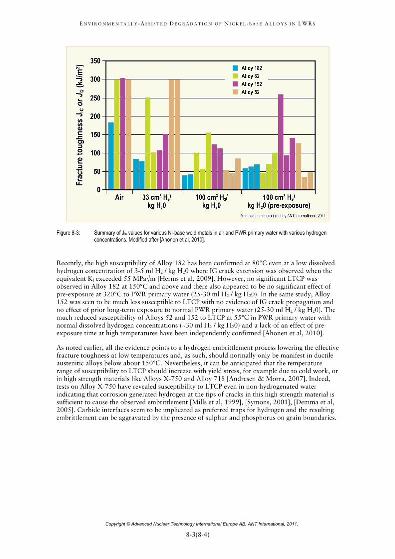
The weld metals Alloys 182, 82H, 82, 52 and 152 all seem to be susceptible to LTCP at low temperatures where typically a reduction of between an order of magnitude and 50% in effective toughness (JIc) compared to in air is observed in PWR primary water at high hydrogen concentrations (~100 ml H2 / kg H20 and above). Alloy 182 is clearly the most susceptible, Alloy 82 slightly less susceptible, and Alloys 52 and 152 the least; (see for example Figure 8-3 [Ahonen et al, 2010]). The effect diminishes with decreasing hydrogen concentrations in primary water and recovers significantly at a typical operational concentration of ~30 ml H2 / kg H20 or close to a shutdown hydrogen concentration of ~5-10 ml H2 / kg H20. At these lower hydrogen concentrations, a mixed mode fracture is observed even in the most susceptible materials [Young et al, 2005a], [Ahonen et al, 2010]. Nevertheless, low effective toughness resulting from cooling down rapidly to low temperature (and low environmental hydrogen concentrations) while maintaining constant load cannot be completely ruled out since the absorbed hydrogen at high temperatures cannot desorb sufficiently rapidly to come to equilibrium with a low shut down concentration at normal cooling rates [Brown & Mills, 2005], [Demma et al, 2005].
E N V I R O N M E N T A L L Y - A S S I S T E D D E G R A D A T I O N O F N I C K E L - B A S E A L L O Y S I N L W R S
Copyright © Advanced Nuclear Technology International Europe AB, ANT International, 2011.
8-3(8-4)=
Figure 8-3: Summary of JIc values for various Ni-base weld metals in air and PWR primary water with various hydrogen concentrations. Modified after [Ahonen et al, 2010].
Recently, the high susceptibility of Alloy 182 has been confirmed at 80°C even at a low dissolved hydrogen concentration of 3-5 ml H2 / kg H20 where IG crack extension was observed when the equivalent KI exceeded 55 MPa√m [Herms et al, 2009]. However, no significant LTCP was observed in Alloy 182 at 150°C and above and there also appeared to be no significant effect of pre-exposure at 320°C to PWR primary water (25-30 ml H2 / kg H20). In the same study, Alloy 152 was seen to be much less susceptible to LTCP with no evidence of IG crack propagation and no effect of prior long-term exposure to normal PWR primary water (25-30 ml H2 / kg H20). The much reduced susceptibility of Alloys 52 and 152 to LTCP at 55°C in PWR primary water with normal dissolved hydrogen concentrations (~30 ml H2 / kg H20) and a lack of an effect of pre-exposure time at high temperatures have been independently confirmed [Ahonen et al, 2010].
As noted earlier, all the evidence points to a hydrogen embrittlement process lowering the effective fracture toughness at low temperatures and, as such, should normally only be manifest in ductile austenitic alloys below about 150°C. Nevertheless, it can be anticipated that the temperature range of susceptibility to LTCP should increase with yield stress, for example due to cold work, or in high strength materials like Alloys X-750 and Alloy 718 [Andresen & Morra, 2007]. Indeed, tests on Alloy X-750 have revealed susceptibility to LTCP even in non-hydrogenated water indicating that corrosion generated hydrogen at the tips of cracks in this high strength material is sufficient to cause the observed embrittlement [Mills et al, 1999], [Symons, 2001], [Demma et al, 2005]. Carbide interfaces seem to be implicated as preferred traps for hydrogen and the resulting embrittlement can be aggravated by the presence of sulphur and phosphorus on grain boundaries.

E N V I R O N M E N T A L L Y - A S S I S T E D D E G R A D A T I O N O F N I C K E L - B A S E A L L O Y S I N L W R S
Copyright © Advanced Nuclear Technology International Europe AB, ANT International, 2011.
9-1(9-6)=
9 Impact of degradation of Nickel-Base Alloys on LWR water chemistries (Pierre Combrade)
Clearly, general corrosion of Ni-base Alloys does not raise any problems for the structural integrity of components although SCC is a potential threat. The challenge for water chemistry specifications is, therefore, to balance:
a) Cation release that is the origin of activity build-up of primary circuits and deposits on the fuel rods.
b) Control CRUD formation, etc. for the various materials of construction used in a given reactor system, including Ni-base Alloys.
c) Specific criteria required for other corrosion phenomena such as flow accelerated corrosion of carbon steels and a variety of localized corrosion modes such as pitting, local wastage, and, finally, EAC, which is clearly the most critical problem of Ni-Base Alloys.
Elements of these compromises required in arriving at the correct balance in water chemistry specifications are now addressed for PWR and BWR primary coolant circuits that contain nickel-base alloy components. More details can be found in the following ANTI reports:
for PWR primary water chemistry, LCC150, LCC2 and LCC5 annual reports and “PWR/VVER Primary Side Coolant Chemistry, Volume I – Technical Basis and Recent Discussions” to be published in 2012;
For PWR secondary water chemistry, LCC3 and LCC5 annual report and “PWR and VVER Secondary System Water Chemistry” [Odar & Nordmann, 2010];
For BWR water chemistry, LCC1, LCC2 and LCC5 annual reports and “BWR Chemistry – Introduction to Chemistry in Nuclear Power Plants with Boiling Water Reactors, Volume I” to be published in 2012.
9.1 PWR primary system chemistry guidelines and corrosion control
Due to the dependencies of surface oxide solubility on pH, water chemistry specifications for PWR Primary Systems impose tight control on pH. This is achieved via injection from the CVCS into the primary system of LiOH51, and boric acid (the latter being the so-called ‘chemical shim’ for assisting in the control of core reactivity). Early water chemistry specifications imposed a pH300°C specification of 6.9 0.2, corresponding to the then perceived minimum in magnetite solubility. More recent specifications have increased this pH300°C specification range to 7.1-7.4 in order to minimise CRUD build-up and the associated shutdown dose rates. There is a limit to which this increase in alkalinity can be allowed, however, which is mainly associated with increases in the corrosion rate of zirconium alloy fuel cladding (Figure 9-1). This puts a limit on the Li concentration of between 3.5 and 5 ppm. Since the boron concentration decreases during the fuel cycle as core reactivity decreases, various lithium/boron chemistry control regimes may be employed. A detailed description of these regimes has been given in the LCC1 report [Lundgren et al, 2005].
A typical range in primary water chemistry conditions is shown in Table 9-1, which encompasses specific values set by the various reactor designers and utility organizations.
50 LWR Coolant Chemistry 51 Note that some plant designs (e.g. the VVER-440 and VVER-1000) use KOH for pH control

E N V I R O N M E N T A L L Y - A S S I S T E D D E G R A D A T I O N O F N I C K E L - B A S E A L L O Y S I N L W R S
Copyright © Advanced Nuclear Technology International Europe AB, ANT International, 2011.
9-2(9-6)=
Figure 9-1: PWR primary coolant chemistry; effect of lithium concentration on various degradation modes. Modified after [Lundgren et al, 2005].
Table 9-1: Typical water chemistry conditions in PWR primary systems. Modified after [Scott & Combrade, 2006].
Typical
Pressure (MPa) 14.2
Temperature (°C) 286-323
Oxygen (ppm) <0.1
Conductivity (µS.cm-1) 1-40
Hydrogen (ml/kg) at STP 20-50
Lithium (ppm) as LiOH 0.1-3.5
Boron (ppm) as H3BO3 0-2300
Chloride (ppm) <0.15
Fluoride (ppm) <0.15
SiO2 (ppm) <0.20
pHT 6.8-7.4
Modified from the original by A.N.T. International, 2011

E N V I R O N M E N T A L L Y - A S S I S T E D D E G R A D A T I O N O F N I C K E L - B A S E A L L O Y S I N L W R S
Copyright © Advanced Nuclear Technology International Europe AB, ANT International, 2011.
9-3(9-6)=
In addition to pH control, PWR primary water contains 25 to 50 cm3SPT/kg of dissolved hydrogen
(imposed by an overpressure of ~15 KPa in the RCS) in order to suppress any radiolytic decomposition products of water, such as oxygen or hydrogen peroxide. The resulting corrosion potentials of all relevant structural materials are close to the hydrogen/water redox potential, as mentioned in Section 3. A minimum limit of dissolved hydrogen of 5-10 cm3
STP/kg is necessary to eliminate any net radiolysis. A maximum limit for the hydrogen overpressure is determined by the need to avoid hydriding of zirconium alloy fuel cladding. The optimum concentration is presently under debate, as alluded to earlier in the context of activity release, and with a view to minimising PWSCC in plants using Alloy 600 and related weld metals. The controversy arises from two points:
The effect of hydrogen on activity of PWR primary circuits (see Section 3.2.2.5) is not fully understood even though the recent trend (in Europe and Japan) is to consider that decreasing dissolved H2 should be favourable.
The effect of hydrogen on PWSCC of Ni-Base Alloys that has given rise to two different approaches:
increase hydrogen in order to decrease PWSCC propagation rates in Alloy 600 components. This is the priority in USA;
decrease hydrogen to increase PWSCC initiation time in Alloy 600 components. This is the trend which presently under study in Japan.
9.2 PWR secondary system chemistry guidelines and corrosion control
There have been a series of changes in water chemistry specifications for PWR secondary systems, with all of them prompted by the need to resolve materials degradation issues in the SG, particularly those related to Ni-base alloy SG tubes.
Because of the preponderance of C&LAS exposed to secondary side water, the initial water chemistries were based on phosphate chemistries, which have been successfully used in the fossil power industry at comparable boiler operating pressures.
The problems encountered with phosphate chemistry in US and German plants (see Section 6) led to the water chemistry specifications being changed to maintain a Na/PO4 ratio between 2.2 and 2.6. The lower limit was defined by the need to avoid wastage of Alloy 600 tubing and the upper limit was defined to avoid caustic cracking of Alloy 600 52.
This tighter control of the new phosphate water chemistry specifications proved hard to maintain. In addition, the sludge pile burden was not fully mitigated, which then forced the adoption of an all-volatile treatment (AVT) water chemistry involving the use of amines and hydrazine. Such a secondary water chemistry had already been used successfully in OTSGs and is now used widely in the PWR fleet internationally. A typical water chemistry range for PWR secondary systems operating under AVT is shown in Table 9-2.
52 It should be pointed out that such problems have not been observed in Alloy 800 tubing widely used in steam generators of Babcock & Wilcox/AECL CANDU design, probably due to their lower operating temperatures.

E N V I R O N M E N T A L L Y - A S S I S T E D D E G R A D A T I O N O F N I C K E L - B A S E A L L O Y S I N L W R S
Copyright © Advanced Nuclear Technology International Europe AB, ANT International, 2011.
10-1(10-42)=
10 References Aaltonen P. et al., The effect of environment on the electric and electrochemical properties of
surface films on Alloy 600 and Alloy 690 in pressurised water reactor primary water, Proceedings of International Symposium Fontevraud IV, SFEN, 1998.
Agrawal A., Examination of Indian Point 3 Steam generator Tube R13C66, Workshop Proceedings: Pitting in Steam Generators, Pittsburgh, PA, 1983, EPRI Report NP-3574 SR, 1984.
Ahlberg E. and Rebensdorff B., in Proc. BNES Conf. Water Chem. Nucl. Reactor Syst. 6, Bournemouth, UK, 12-15 Oct. 1992, Vol.2, 278-5/8, 1992.
Ahonen M., Ehrnstén U. and Hänninen H., Low temperature crack propagation of nickel-based weld metals in hydrogenated PWR primary water, Proceedings of Fontevraud 7, SFEN, 2010.
Airey G. P., The Effect of Carbon Content and Thermal Treatment on the SCC Behavior of Inconel Alloy 600 Steam Generator Tubing, Corrosion, Vol. 35, p. 129, 1979.
Airey G. P., The stress corrosion cracking (SCC) performance of Inconel Alloy 600 in pure and primary water environments, Proceedings of 1st International Symposium on Environmental Degradation of Materials in Nuclear Power Systems-Water Reactors, pp. 462-476, National Association of Corrosion Engineers, 1984.
Akashi M and Nakayama G., Effect of acceleration factors on the probability distribution of SCC initiation life of Alloys 600, 182 and 82 in high temperature and high purity water environments, in Proceedings of 9th Conference on Degradation of materials in Nuclear Power systems Newport Beach CA 1999.
Akutagawa D., Nagata N., Dozaki K., Takiguchi H., Norring K., Jenssen A. and Molander A., Environmental mitigation of PWSCC initiation – Low DH chemistry for PWR primary systems, Proceedings of 14th International Symposium on Environmental Degradation in Nuclear Power Systems - Water Reactors, pp. 306 – 315, Virginia Beach, VA, ANS 2009.
Alexandreanu B., Chopra O. K. and Shack W. J., The effect of grain orientation on the cracking behavior of Alloy 182 in PWR environment, Proceedings of the 12th International Conference on Environmental Degradation of Materials in Nuclear Power System – Water Reactors, pp. 579-587, TMS (The Minerals, Metals & Materials Society), 2005.
Alexandreanu B., Chopra O. K., Cullen W. H. and Shack W. J., Crack growth rates in PWR environment of nickel-base alloy welds from Davis-Besse and V. C. Summer power plants, Proceedings of Fontevraud 6, pp. 311-322, SFEN 2006.
Alexandreanu B., Chopra O. and Shack W. J., Determination of the activation energy for SCC crack growth for Alloy 182 weld in a PWR environment, Proceedings of 13th International Conference on Environmental Degradation of Materials in Nuclear Power Systems, Whistler, British Columbia, Canadian Nuclear Society 2007a.
Alexandreanu B., Chopra O. and Shack W., The stress corrosion cracking behaviour of Alloys 690 and 152 weld in a PWR environment, Proceedings of 13th International Symposium on Environmental Degradation in Nuclear Power Systems - Water Reactors, Whistler, British Columbia, Canada, Canadian Nuclear Society 2007b.
Alexandreanu B., Yang Y., Chen Y. and Shack W. J., The stress corrosion cracking behaviour of Alloys 690 and 152 weld in a PWR environment, Proceedings of 14th International Symposium on Environmental Degradation in Nuclear Power Systems - Water Reactors, pp. 239 – 250, Virginia Beach, VA, ANS 2009.

E N V I R O N M E N T A L L Y - A S S I S T E D D E G R A D A T I O N O F N I C K E L - B A S E A L L O Y S I N L W R S
Copyright © Advanced Nuclear Technology International Europe AB, ANT International, 2011.
10-2(10-42)=
Allmon W. E., Daniel P. L. and Potterton S. J., Conditions for the Chemical reduction of Sulfates in an Aqueous Environment, Proceedings: Workshop on the Role of Sulfur Species on the Secondary-Side Degradation of Alloy 600 and Related Alloys, Baltimore, Ma, USA, 1985, EPRI report NP 6710-SD, 1990.
Amzallag C. and Vaillant F., Stress corrosion crack propagation rates in reactor vessel head penetrations in Alloy 600, Proceedings of 9th International Symposium on Environmental Degradation of Materials in Nuclear Power Systems – Water Reactors, pp. 235-241, Newport Beach, CA, The Metallurgical Society 1999.
Amzallag C., Le Hong S., Pagès C. and Gelpi A., Stress corrosion life assessment of Alloy 600 components, Proceedings of 9th International Symposium on Environmental Degradation of Materials in Nuclear Power Systems – Water Reactors, pp. 243-250, Newport Beach, CA, The Metallurgical Society, 1999.
Amzallag C., LeHong S., Benhamou C., Gelpi A., Methodology used to rank the stress corrosion susceptibility of Alloy 600 PWR components, Pressure Vessel and Piping Conference, Seattle: ASME 2000.
Amzallag C., Boursier J-M, Pages C. and Gimond C., Stress corrosion life assessment of 182 and 82 welds used in PWR components, Proceedings of 10th International Conference on Environmental Degradation of Materials in Nuclear Power Systems-Water Reactors, Lake Tahoe, August 5-9, 2001, NACE International 2002.
Amzallag C., Boursier J-M., Pages C. and Gimond C., Stress corrosion life experience of 182 and 82 welds in French PWRs, Proceedings of Fontevraud 5, pp. 69-79, SFEN 2002.
Andresen P. L., Modelling of water and material chemistry effects on crack tip chemistry and resulting crack growth kinetics, Proceedings 3rd Int. Conf. Environmental Degradation of Materials in Nuclear Power Systems - Water Reactors, Traverse City, AIME, pp. 301-314, 1987.
Andresen P. L., Vasatis I and Ford P., Behaviour of short cracks in stainless steel and Inconel in 288oC water, Paper 495, Corrosion/90, NACE, Houston 1990.
Andresen P. L., Fracture mechanics data and modelling of environmental cracking of nickel-base alloys in high temperature water, Corrosion Journal, Vol. 47, pp. 917-938, December 1991.
Andresen P. L., Effect of temperature on crack growth rate in sensitized Type 304 stainless steel and Alloy 600, Corrosion Journal, Vol. 49, No.9, pp. 714-725, 1993.
Andresen P. L. and Angeliu T. M., Effects of zinc additions on the stress corrosion crack growth rate of sensitized stainless steel, Alloy 600 and Alloy 182 weld metal in 288°C water, Corrosion/95, Paper 409, NACE 1995.
Andresen P. L., SCC testing and quality control considerations, Proceedings. Proceedings 9th Int. Symposium on Environmental Degradation of Materials in Nuclear Power Systems - Water Reactors, Traverse City, (Eds.) Bruemmer S., Ford F. P., pp.411-422, AIME 1999.
Andresen P. L., Angeliu T. M., Emigh P. W. and Horn R. M., Crack growth rate behaviour of nickel-alloys, Corrosion/2000, Paper 00202, NACE, 2000.
Andresen P. L., Emigh P. E. and Young L. M., Mechanistic and kinetic role of yield strength / cold work / martensite, H2, temperature, and composition on SCC of stainless steels, Proceedings. Int. Symp. on Mechanisms of Material Degradation in Non-Destructive Evaluation in Light Water Reactors, Osaka, Japan, May 2002, published by Inst. of Nuclear Safety System, Japan, pp. 215-239. 2002.

E N V I R O N M E N T A L L Y - A S S I S T E D D E G R A D A T I O N O F N I C K E L - B A S E A L L O Y S I N L W R S
Copyright © Advanced Nuclear Technology International Europe AB, ANT International, 2011.
10-3(10-42)=
Andresen P. L., Emigh P. W., Morra M. M. and Horn R. M., Effects of yield strength, corrosion potential, stress intensity factor, silicon and grain boundary character on the SCC of stainless steels, Proceedings of 11th Int. Symp. on Environmental Degradation of Materials in Nuclear Power Systems – Water Reactors, pp. 816-831, ANS, 2003.
Andresen P. L. and Morra M. Effects of Si on SCC of irradiated stainless steels and nickel alloys, Proceedings of 12th International Conference on Environmental Degradation in Nuclear Power Systems–Water Reactors, Skamania Lodge, Eds. L. Nelson, P. King, The Metallurgical Society, pp. 87-108 August 5-9, 2005.
Andresen P. L. Emigh P. W., Morra M.M. and Hickling J., Effects of PWR Primary Water Chemistry and Deaerated Water on SCC, Proceedings of the 12th International Conference on Environmental Degradation of Materials in Nuclear Power System –Water Reactors – Edited by T.R. Allen, P.J. King, and L. Nelson TMS (The Minerals, Metals & Materials Society), 989, 2005.
Andresen P. L., SCC of nickel-base Alloys 182 and 82 weld metals in BWR water, in Expert Panel Report on Proactive Materials Degradation Assessment, USNRC NUREG Report CR-6923, February 2007.
Andresen P. L. and Morra M. M., Emerging issues in environmental cracking in hot water, Proceedings of 13th International Symposium on Environmental Degradation in Nuclear Power Systems - Water Reactors, Whistler, British Columbia, Canada, Canadian Nuclear Society 2007.
Andresen P. L., Hickling J., Ahluwalia K. S. and Wilson J. A., Effects of PWR primary chemistry on PWSCC of nickel alloys, Proceedings of 13th International Conference on Environmental Degradation of Materials in Nuclear Power Systems, Whistler, British Columbia, Canadian Nuclear Society 2007a.
Andresen P. L., Morra M. M., Hickling J., Ahluwalia A. and Wilson J., PWSCC of Alloys 690, 52 and 152, Proceedings of 13th International Symposium on Environmental Degradation in Nuclear Power Systems - Water Reactors, Whistler, British Columbia, Canada, Canadian Nuclear Society 2007b.
Andresen P. L., Hickling J., Ahluwalia K. and Wilson J., Effects of hydrogen on stress corrosion crack growth rate of nickel alloys in high temperature water, Corrosion, Vol.64, pp. 707-720, 2008.
Andresen P. L., SCC of Controlled Chemistry Alloy 182 and 82 Weld Metals in BWR Water, Proceedings of 14th International Conference on Environmental Degradation in Nuclear Power Systems, Eds. Allen, Busby Pub American Nuclear Society, Virginia Beach, pp. 382-408, 2009a.
Andresen P. L., Unusual cold work and strain rate effects on SCC, Proceedings of 14th International Symposium on Environmental Degradation in Nuclear Power Systems - Water Reactors, pp. 805 – 845, Virginia Beach, VA, ANS 2009b.
Andresen P. L., Reid R. and Wilson J., SCC mitigation of Ni alloys and weld metals by optimizing dissolved hydrogen, Proceedings of 14th International Symposium on Environmental Degradation in Nuclear Power Systems - Water Reactors, pp. 345 – 372, Virginia Beach, VA, ANS 2009a.
Andresen P. L., Morra M. M., Ahluwalia A. and Wilson J., Effect of deformation and orientation on SCC of Alloy 690, Proceedings of 14th International Symposium on Environmental Degradation in Nuclear Power Systems - Water Reactors, pp. 846 – 887, Virginia Beach, VA, ANS 2009b.
Andresen P. L., Morra M. M. and Ahluwalia A., SCC of Alloy 690 and its weld metals, Proceedings of Fontevraud 7, SFEN 2010a.