substation batteries and chargers opsaf-12-008 1. scope live
TRANSCRIPT
Substation Batteries and Chargers OPSAF-12-008 Issue No.3
________________________________________________________________________________ © SP Power Systems Limited Page 1 of 14 LWM 3.2
1. SCOPE
This section of the Live Working Manual details the procedures to be followed when working on alkaline
or acid substation batteries of any type or voltage. It also covers work on or near to battery charging
Apparatus that is Live.
All work on substation batteries shall be considered Live work.
The procedures apply the principles established by the ScottishPower Safety Rules (Electrical and
Mechanical) to achieve Safety from the System and in particular OPSAF-10-012 (PSSI 12) - Low
Voltage Apparatus.
This document does not cover any work carried out on batteries supplying overhead pole mounted
Apparatus, or telecommunication and tele-control equipment eg. RTU batteries.
2. ISSUE RECORD
This is a Reference document. The current version is held on the EN Document Library. It is your responsibility to ensure you work to the current version.
Issue Date Issue No Author Amendment Details
March 2018 3 Dave Naylor Mark Brookman
Major update. Now includes dry cells and work on chargers.
3. ISSUE AUTHORITY
Author Owner Issue Authority
Name Dave Naylor Title Operational Safety Engineer
Name Gary Evans Title Operational Assurance Manager
Name Ross Galbraith Title Health & Safety Director ………………………………… Date: …………………………
4. REVIEW
This is a Reference document which has a 5 year retention period after which a reminder will be issued to review and extend retention or archive.
5. DISTRIBUTION
This document is part of the Live Working Manual but does not have a maintained distribution list.
26th March 2018

Substation Batteries and Chargers OPSAF-12-008 Issue No.3
________________________________________________________________________________ © SP Power Systems Limited Page 2 of 14 LWM 3.2
6. CONTENTS
1. SCOPE .......................................................................................................................................... 1
2. ISSUE RECORD ........................................................................................................................... 1
3. ISSUE AUTHORITY ...................................................................................................................... 1
4. REVIEW ........................................................................................................................................ 1
5. DISTRIBUTION ............................................................................................................................. 1
6. CONTENTS ................................................................................................................................... 2
7. REFERENCE OR RELATED DOCUMENTS ............................................................................... 3
8. DEFINITIONS ................................................................................................................................ 3
9. ASSESSMENT .............................................................................................................................. 3
10. DANGERS ..................................................................................................................................... 3
11. ADDITIONAL HAZARDS .............................................................................................................. 4
12. TRANSPORTATION, STORAGE AND DISPOSAL ..................................................................... 4
12.1 TRANSPORTATION OF WET CELLS .............................................................................................. 4 12.2 TRANSPORTATION OF DRY CELLS............................................................................................... 4 12.3 STORAGE OF WET CELLS ........................................................................................................... 4 12.4 STORAGE OF DRY CELLS ........................................................................................................... 5 12.5 DISPOSAL OF CELLS .................................................................................................................. 5
13. PROCEDURE WL1.06 WORK ON SUBSTATION BATTERY CELLS .......................................... 5
13.1 BATTERY REPLACEMENT WORK FLOW CHART. ............................................................................ 6 13.2 CHANGING WET CELLS ............................................................................................................. 6 13.3 REPLACING COMPLETE SETS OF WET CELLS:- ............................................................................. 8 13.4 REFILLING OR TOPPING-UP WET CELLS OF ANY VOLTAGE. ........................................................... 9 13.5 CONVERTING 30V WET CELLS TO DRY CELLS :- .......................................................................... 9 13.6 REPLACING PACKS OF 30V DRY CELLS ..................................................................................... 10 13.7 REPLACING DRY CELLS OTHER THAN 30V PACKS ...................................................................... 11 13.8 BATTERIES WITH VOLTAGE TAPPING(S) .................................................................................... 12 13.9 REPLACING TRANSLAY BATTERIES .......................................................................................... 13 13.10 WORK ON BATTERY CHARGERS .............................................................................................. 14
14. APPENDIX 1 – EXAMPLE TEMPORARY CHARGER AND BATTERY SETS ......................... 14
Substation Batteries and Chargers OPSAF-12-008 Issue No.3
________________________________________________________________________________ © SP Power Systems Limited Page 3 of 14 LWM 3.2
7. REFERENCE OR RELATED DOCUMENTS
Health, Safety & Environmental Handbook OPSAF-10-012 (PSSI 12) LV Apparatus BATT-12-001 Ancillary Plant: Batteries and Chargers
8. DEFINITIONS
Terms printed in bold type are as defined in the Scottish Power Safety Rules (Electrical and Mechanical).
9. ASSESSMENT
All work on or so near Live exposed LV conductors that Danger may arise requires assessment before
the commencement of work to ensure that Danger is managed during the course of the work. This
assessment will be carried out by a suitably Authorised Person who holds the appropriate authorisation
to undertake the work. Note that battery systems are unique in that it is not possible for them to be
Isolated in order to remove electrical Danger.
In all cases, as part of the assessment, Apparatus shall be subjected to a visual inspection prior to the start of any work to ensure that Danger will not arise due to the condition of the Apparatus. Refer to document BATT-12-001 for guidance on inspection of batteries. Attention shall be paid to any abnormal smell for example hydrogen sulphide gas given off by lead acid cells may indicate low electrolyte or cells which are overcharging or degraded.
Should this initial inspection reveal any significant deficiency in the Apparatus which could give rise to Danger, no attempt shall be made to work on the Apparatus until a supervisor with appropriate knowledge has been consulted and assessed the situation.
10. DANGERS
The main Dangers to Persons carrying out work or testing on batteries and chargers are electric shock,
explosion, or burns arising from:
1. The ignition of hydrogen which is given off by cells during the process of charging. The gas may be ignited by naked flames and cigarettes or by sparks if cell terminals are accidentally earthed or shorted together (i.e. positive and negative terminals directly connected).
2. Contact with electrolyte contained within the cells. Burns can result from contact with either
alkaline or acid electrolyte.
3. Fire, overheating and the expulsion of electrolyte from cells. This may occur if cells are short-circuited.
4. Arc energy, heat and light released from cells if they are short-circuited. The arc energy released may cause burns from conductors being heated rapidly or from the material causing the short-circuit.
5. Work being carried out on or in proximity to Live AC or DC conductors and battery cells.
Substation Batteries and Chargers OPSAF-12-008 Issue No.3
________________________________________________________________________________ © SP Power Systems Limited Page 4 of 14 LWM 3.2
11. ADDITIONAL HAZARDS
Whilst not directly introducing Danger, the following hazards may arise as a result of undertaking work on batteries or chargers with the potential to harm to Persons working on or near the System, or to the general public and other people at work. These procedures have been written including steps to mitigate the hazards.
1. Loss of protection supplies to a circuit being worked upon or to adjacent circuits.
2. Inadvertent operation of protection systems on a circuit being worked upon or adjacent
circuits.
12. TRANSPORTATION, STORAGE AND DISPOSAL
Note that the Dangers identified in section 10 exist while cells are transported, stored and disposed of. Suitable care shall be taken to avoid those Dangers.
12.1 Transportation of wet cells
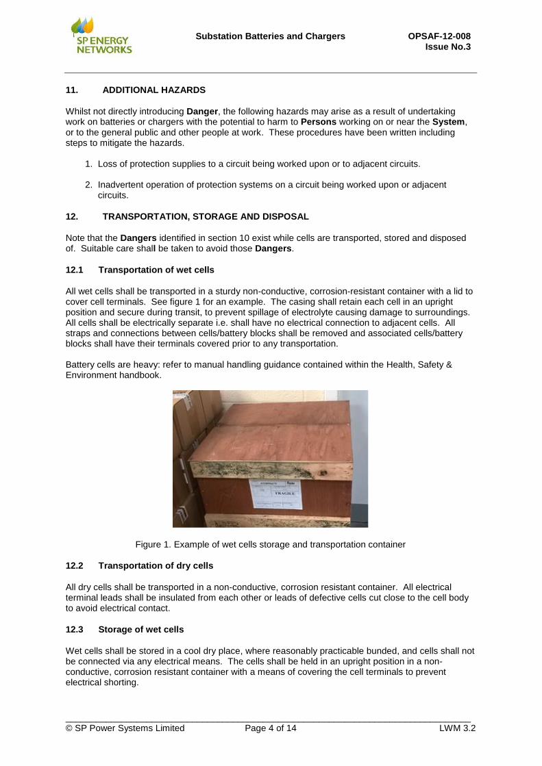
All wet cells shall be transported in a sturdy non-conductive, corrosion-resistant container with a lid to cover cell terminals. See figure 1 for an example. The casing shall retain each cell in an upright position and secure during transit, to prevent spillage of electrolyte causing damage to surroundings. All cells shall be electrically separate i.e. shall have no electrical connection to adjacent cells. All straps and connections between cells/battery blocks shall be removed and associated cells/battery blocks shall have their terminals covered prior to any transportation. Battery cells are heavy: refer to manual handling guidance contained within the Health, Safety & Environment handbook.
Figure 1. Example of wet cells storage and transportation container
12.2 Transportation of dry cells
All dry cells shall be transported in a non-conductive, corrosion resistant container. All electrical terminal leads shall be insulated from each other or leads of defective cells cut close to the cell body to avoid electrical contact.
12.3 Storage of wet cells
Wet cells shall be stored in a cool dry place, where reasonably practicable bunded, and cells shall not be connected via any electrical means. The cells shall be held in an upright position in a non-conductive, corrosion resistant container with a means of covering the cell terminals to prevent electrical shorting.
Substation Batteries and Chargers OPSAF-12-008 Issue No.3
________________________________________________________________________________ © SP Power Systems Limited Page 5 of 14 LWM 3.2
12.4 Storage of dry cells
All dry cells shall be stored in a cool dry place in a non-conductive container with all electrical terminal leads insulated from each other. New cells shall be retained in the manufacturer’s packaging until ready for use. Electrical terminal leads of used or defective cells shall be cut close to the cell body or insulated from all surroundings.
12.5 Disposal of cells
Cells shall only be removed from the storage area for disposal by a licensed waste specialist. Any electrolyte spillage shall be contained or mopped using appropriate absorbent materials which shall be disposed of in an Approved manner, as Active Waste. Details of the licensed contractor will be available from the local Depot Manager.
13. PROCEDURE WL1.06 WORK ON SUBSTATION BATTERY CELLS
Where it may introduce Danger, the AC supply to a battery charger shall where reasonably practicable be Isolated before commencement of work. If it is not reasonably practicable then the site specific risk assessment shall consider if work may proceed safely with appropriate control measures in place. Consideration shall be given to the proximity of Live AC terminals within the charger unit/battery cabinet. Control measures to control the Danger from adjacent Live AC terminals may include:
isolating the AC supply,
use of Approved shrouding
wearing Approved rubber gloves
using an Approved insulated mat. Approved PPE including flame retardant coveralls (fastened up to neck and wrists) and a minimum of light eye protection shall be worn. Appropriate gloves shall be selected to protect the skin. Certain tasks in this procedure may require face protection to be augmented by the use of a full face visor. The risk assessment shall consider the effect of any sudden movements inside a panel or cabinet caused by involuntary reaction to arcing or flashover that may result in secondary injuries e.g. cuts, abrasions and impact injuries. Before any work takes place on batteries or cells where there may be Danger, Approved shrouding shall be placed over any exposed terminals of adjacent cells. Selected tasks within this procedure may be undertaken by an Authorised Person working unaccompanied.
Task Accompaniment required?
Changing Wet Cells Yes
Replacing complete sets of wet cells Yes
Refilling or topping-up wet cells of any voltage
May be completed unaccompanied*
Converting 30V wet cells to dry cells Yes
Replacing packs of 30V dry cells May be completed unaccompanied*
Replacing dry cells other than 30V packs May be completed unaccompanied*
Batteries with voltage tapping(s) Yes
Replacing Translay Batteries May be completed unaccompanied*
Work on Battery Chargers Yes
*The risk assessment shall consider if being accompanied by another Authorised Person will substantially contribute towards the implementation of a safe system of work and if so, a second Authorised Person shall be present.

Substation Batteries and Chargers OPSAF-12-008 Issue No.3
________________________________________________________________________________ © SP Power Systems Limited Page 6 of 14 LWM 3.2
Where reasonably practicable, when working on any battery supplying protection or tripping systems where a disconnection is to take place, then a slave temporary battery of equal or greater electrical capability shall be connected in parallel before work commences. Refer to appendix 1 for examples of temporary chargers and battery sets. Under some circumstances – depending on battery supervision or protection, switching off a battery charger may result in operation of circuit breakers in the substation. Particular attention shall be paid to this hazard.
13.1 Battery replacement work flow chart.
This flow chart describes the generic approach for replacement of either wet or dry cells. Refer to the specific task below for full detail.
Inform Control Person before commencing work
Isolate charger supply if required (see text) otherwise switch off battery charger
Ventilate the area where batteries/ cells are located by opening doors to battery room/battery cabinets
Remove permanent battery and replace defective cell(s) /
battery blocks
Reconnect refurbished battery
Remove temporary battery
Carry out risk assessment for scope of work
Restore AC supply to charger (if required) and Switch on charger. Check that charger
is operating correctly and that charging rate and battery voltage is correct
Battery block / cell replacement requirement
identified
Primary S/S or Grid S/S
Secondary S/S
Connect temp batteries using suitable connection leads using
sockets provided
Potential to install temporary battery
Facility to connecton dist board
No facility to connecton dist board
NB: Ensure Fuseways to reduced voltage tappings are isolated and tapped load is supplied from a separate source
Not possible to Install temporary Battery
Finish work
Primary S/S or Grid S/S
Secondary S/S
Inform Control Person on completion of work
Remove any insulating boards covering terminals of cells on which work is to be done
Assemble bypass assembly similarly rated cells/battery blocks with bypass leads and clamps to bypass out the defective cell and each adjacent
cell/battery blocks
Disconnect the defective cell and replace with a healthy cell
Remove the bypass cell assembly.
Replace any insulating boards which have been removed.
Clamp the bypass leads to the adjacent cell interconnectors, effectively bypassing the
defective cell and each adjacent cell NB: Ensure separate sources are removed from reduced voltage
tappings and fuses and links are reinserted
Connect temporary battery, positive/positive and negative/
negative across permanent battery using suitable
connection leads
Repeat process to replace additional defective
cells / battery blocks
13.2 Changing Wet Cells
This section is for the replacement of one or a number of individual wet cells in a battery, or where or
cells are to be removed for cleaning/maintenance.
While working on wet cells, in addition to the basic PPE specified above, a full face visor and PVC gloves
shall be worn when risk assessment does not require the use of Approved rubber gloves for electrical
protection. Only Approved insulated tools shall be used and tools used on lead acid cells shall not be
used for working on alkaline cells and vice versa.
This task shall only be undertaken with the accompaniment of a second Authorised Person.
Defective cells may only be changed either one at a time or in groups of adjacent defective cells. While
the cell(s) are being changed, it is important that the battery can still perform its duty (e.g. CB tripping).
To ensure this, cell connections shall not be broken before a bypass, comprising a minimum of three

Substation Batteries and Chargers OPSAF-12-008 Issue No.3
________________________________________________________________________________ © SP Power Systems Limited Page 7 of 14 LWM 3.2
cells of equal capacity, is put in to replace the defective cell(s) and one cell on either side of it/them (see
drawing Figure 2). The current rating of the bypass leads required is dependent on the battery size:
For 30V or 50V batteries, Approved 10 sq.mm. copper double insulated bypass leads are required;
For 110V batteries, Approved 25 sq.mm. copper double insulated bypass leads are required.
Step 1 Inform appropriate Persons before commencing work. This will include advising the Control
Person when working in Primary/Grid substations. Step 2 Isolate AC supply if required. Step 3 Switch off battery charger. Step 4 Ensure any gases are dissipated by opening doors and thoroughly ventilating the area in
which the cells are placed. Step 5 Remove any insulating boards covering terminals of cells on which work is to be done. Apply
Approved temporary shrouding to any remaining exposed terminals of adjacent cells. Step 6 Assemble three (or more) similarly rated cells with bypass leads and clamps to bypass the
defective cell(s) and one adjacent cell on each side. (See Figure 2). Step 7 Clamp the bypass leads to the adjacent cell interconnectors, effectively bypassing the
defective cell(s) and one adjacent cell on each side. Step 8 Disconnect the defective cell(s) and replace with healthy cell(s). Step 9 Remove the bypass cell assembly. Step 10 Remove temporary shrouding and replace any insulating boards which have been removed. Step 11 Restore AC supply if required and switch on the battery charger unit. Check that charger is
operating correctly and that the charging rate and battery voltage is correct. Step 12 Inform the Control Person that work is complete, so that any remote alarms can be
cleared and depletions removed from the System diagram.

Substation Batteries and Chargers OPSAF-12-008 Issue No.3
________________________________________________________________________________ © SP Power Systems Limited Page 8 of 14 LWM 3.2
Figure 2. Standard arrangement for replacing individual cell(s). Capacity of cells shall be greater than
or equal to the cells being replaced.
13.3 Replacing complete sets of wet cells:-
This section is for the replacement of all of the wet cells in a battery of any voltage.
While working on wet cells, in addition to the basic PPE specified in section 13, a full face visor and PVC
gloves shall be worn when risk assessment does not require the use of Approved rubber gloves for
electrical protection. Only Approved insulated tools shall be used and tools used on lead acid cells shall
not be used for working on alkaline cells and vice versa.
This task shall only be undertaken with the accompaniment of a second Authorised Person.
Where chargers or distribution boards are fitted with an auxiliary socket a temporary battery may be
plugged into the charger before work commences to change the existing battery. Otherwise a temporary
battery of appropriate electrical capability shall be connected in parallel to the existing battery (i.e. with
outgoing terminals of batteries connected positive/positive and negative/negative) before the existing
battery is disconnected from the charger. Note the important requirements of section 13.8 if there are
multiple voltage tappings taken from the battery being worked on. Step 1 Inform appropriate Persons before commencing work. This will include advising the Control
Person when working in Primary/Grid substations. Step 2 Isolate AC supply if required and switch off battery charger.

Substation Batteries and Chargers OPSAF-12-008 Issue No.3
________________________________________________________________________________ © SP Power Systems Limited Page 9 of 14 LWM 3.2
Step 3 Allow any gases to dissipate by opening doors and thoroughly ventilating the area where the
cells are kept. Step 4 Assemble temporary slave cells adjacent to cells to be replaced. These may be battery
blocks linked or preferably pre-packaged temporary sets. Step 5 Approved temporary shrouding, insulating mat and the use of Approved rubber gloves or
other protective gloves shall be considered subject to site specific risk assessment. Step 6 Connect the slave cells in parallel using Approved bypass leads. Step 7 Remove and replace defective cell with healthy cells using Approved insulated tools. Step 8 Remove bypass leads and slave cells from work area. Step 9 Ensure voltage levels are correct for system protection needs. Step 10 Restore AC supply if required and switch on the battery charger unit. Check that charger is
operating correctly and that the charging rate and battery voltage is correct. Step 11 Remove Approved shrouding (if applied earlier). Step 12 Inform the Control Person that work is complete, so that any remote alarms can be
cleared and depletions removed from the System diagram.
13.4 Refilling or topping-up wet cells of any voltage.
Persons undertaking this task need not be accompanied, however if, as part of the risk assessment carried out prior to work commencing, it is concluded that being accompanied by another Authorised Person will substantially contribute towards the implementation of a safe system of work, a second Authorised Person shall be present. When topping-up of wet cell(s) is required, particular care shall be taken to avoid Danger from electrolyte which is present in the cells to be topped-up. Great care shall be taken to minimise the disruption to the electrolyte within the cells. Any electrolyte displacement may cause injury or damage to Persons nearby or surrounding surfaces / materials. Any spillage must be contained or mopped using appropriate absorbent materials which shall be disposed of in an Approved manner, as Active Waste. While working on wet cells, in addition to the basic PPE specified in section 13 above, a full face visor and PVC gloves shall be worn when risk assessment does not require the use of Approved rubber gloves for electrical protection. All cells in the battery shall be inspected before any are topped-up. Refer to document BATT-12-001 for guidance on inspection of batteries. Only de-ionised or distilled water shall be used for topping-up and Approved means of refilling the cells shall be used (ie. non-conductive funnels or water pump dispensers).
The electrolyte level of a cell must not exceed the mark displayed on the cell casing, making allowance for expansion due to changes in ambient temperature -any electrolyte escaping from the cell will cause accelerated corrosion to the positive cell terminal.
13.5 Converting 30V wet cells to dry cells :-
This task shall only be undertaken with the accompaniment of a second Authorised Person.

Substation Batteries and Chargers OPSAF-12-008 Issue No.3
________________________________________________________________________________ © SP Power Systems Limited Page 10 of 14 LWM 3.2
In addition to the basic PPE identified in section 12, when working with wet cells a full face visor and PVC
gloves shall be worn when risk assessment does not require the use of Approved rubber gloves for
electrical protection.
In addition to changing the cells, the charger shall be re-configured to prevent overcharging the dry cells which will lead to their early failure. Step 1 If required, inform appropriate persons before commencing work. Step 2 Allow any gases to dissipate by opening doors and thoroughly ventilating the area in which
the cells are placed.
Step 3 Isolate the 230V supply to the battery charging unit. Step 4 Connect slave cells to retain 30V dc supply for protection system functionality Step 5 Remove DC supply from charging unit to wet cells. Step 6 Remove the wet cells from the charger cabinet and install new dry cell pack. Step 7 Carry out charger conversion to the manufacturer’s instructions, restoring the DC supply from
charging unit to dry battery cells. Step 8 Disconnect slave cells. Step 9 Ensure DC output voltage will be correct for protection systems and reconnect 230V supply
to newly converted charger unit. Step 10 Inform appropriate persons that work is complete – this may include advising the Control
Person if there is a depletion to remove from the System diagram.
13.6 Replacing packs of 30V dry cells
This task is for like-for-like replacement of 30V dry cell packs. Persons undertaking this task need not be accompanied, however if, as part of the risk assessment carried out prior to work commencing, it is concluded that being accompanied by another Authorised Person will substantially contribute towards the implementation of a safe system of work, a second Authorised Person shall be present. 30V dry cell packs consist of fifteen 2V cells connected in series. These cells are held on a rigid plastic base and covered in a plastic insulated wrapping. Three electrical leads: positive, negative and a 22/15V tapping for different protection systems are available for connection on certain makes of cells – see figure 3. Step 1 If required, inform appropriate persons before commencing work. Step 2 Isolate the 230V supply to the charger Step 3 When replacing defective cells, this shall be completed without delay as the protection
systems are without their 30V DC supply. Step 4 Identify 30V cell leads to be disconnected, and disconnect them one at a time and cover
bared conductor with insulation tape/material. Never allow the positive and negative leads to touch each other. Remove the old dry pack cells from charger.
Step 5 Install and connect new dry pack cells leads, only baring and connecting one lead at a time. Step 6 When the connection of new cells is complete, check the voltage of cells is near 30V as the
cells may need a short amount of time to charge and attain the optimum voltage required.

Substation Batteries and Chargers OPSAF-12-008 Issue No.3
________________________________________________________________________________ © SP Power Systems Limited Page 11 of 14 LWM 3.2
Step 7 The old dry cell leads shall be cut one at a time as close to the cells and insulated from each other as some residual charge may still be present.
Step 8 Inform appropriate persons that work is complete – this may include advising the Control
Person if there is a depletion to remove from the System diagram.
Figure 3. Examples of 30V dry cell packs – note three leads – 30V, 22V and 0V.
13.7 Replacing dry cells other than 30V packs
This task is for the replacement either of an individual dry cell or all dry cells in a battery of any voltage
other than where packs of 30V cells are used. The approach of installing a temporary (slave) battery is
to be adopted whether the work includes replacing a single cell or all of the cells in the battery.
Figure 4 – typical dry cell
Substation Batteries and Chargers OPSAF-12-008 Issue No.3
________________________________________________________________________________ © SP Power Systems Limited Page 12 of 14 LWM 3.2
Approved rubber gloves shall be worn when risk assessment requires electrical protection for the hands.
Only Approved insulated tools shall be used.
It is expected that the accompaniment of a second Authorised Person will be required to assist with this
task – partly due to the size and weight of the dry cells – however depending on the work to be
undertaken a second Authorised Person need not be present if the risk assessment determines that it
will not contribute towards the implementation of a safe system of work.
Where chargers or distribution boards are fitted with an auxiliary socket a temporary battery may be
plugged into the charger before work commences to change the existing battery. Otherwise temporary
batteries of appropriate electrical capability shall be connected in parallel to the existing battery (i.e. with
outgoing terminals of batteries connected positive/positive and negative/negative) before the existing
battery is disconnected from the charger. Note the important requirements of section 13.8 if there are
multiple voltage tappings taken from the battery being worked on. Step 1 Inform appropriate Persons before commencing work. This will include advising the Control
Person when working in Primary/Grid substations. Step 2 Isolate AC supply if required and switch off battery charger. Step 3 Assemble temporary slave cells adjacent to cells to be replaced. These may be battery
blocks linked or preferably pre-packaged temporary sets. Step 4 Approved shrouding, insulating mat and the use of Approved rubber gloves or other
protective gloves shall be considered subject to site specific risk assessment. Step 5 Connect the slave cells in parallel with the existing battery and (where necessary) to lower
voltage tappings using Approved bypass leads or by the socket provided. Step 6 Remove and replace defective cell(s) with healthy cell(s) using Approved insulated tools. Step 7 Remove bypass leads and slave cells from work area. Step 8 Ensure voltage levels are correct for system protection needs. Step 9 Restore AC supply if required and switch on the battery charger unit. Check that charger is
operating correctly and that the charging rate and battery voltage is correct. Step 10 Remove Approved shrouding (if applied earlier). Step 11 Inform the Control Person that work is complete, so that any remote alarms can be
cleared and depletions removed from the System diagram.
13.8 Batteries with voltage tapping(s)
When disconnecting and/or replacing a set of cells that has a lower voltage tapping (ie.110V/48V/30V set with a lower tapping), consideration shall be given to the voltage tapping. Each protection system voltage shall have its own slave set for example when replacing a 48V set with a 30V tapping, the tapping for 30V shall be replaced by a power pack or slave set connected to the 30V outgoing connection for the duration of the work. See figure 5 showing 48V set with 30V tapping, if replacing the 48V set and covering only 48V with slave set the lower voltage tapping will not be present which would allow the 48V protection relays to operate but would render the 30V protection systems and solenoids/trip coils inoperative. All protection system battery output voltages shall be confirmed present at the end of work.

Substation Batteries and Chargers OPSAF-12-008 Issue No.3
________________________________________________________________________________ © SP Power Systems Limited Page 13 of 14 LWM 3.2
Figure 5 illustration of cells with voltage tapping
13.9 Replacing Translay Batteries
This task refers to battery systems associated with overhead Translay protection schemes as deployed on the SPM 33kV distribution network. On these schemes the battery cells are located in a wall-mounted intertripping cabinet and are accessed by means of a drawer arrangement at the base of the cabinet. No charger system is present and the cells are replaced on a periodic basis. Cells shall be replaced as a complete set wherever possible. It should be noted that with the drawer pulled open the battery terminals are disconnected from the protection panel wiring by means of a contact arrangement at the rear of the drawer. All Danger associated with contact with “hot” wiring in the cabinet are therefore removed when the drawer is pulled out of the cabinet housing. Persons undertaking this task need not be accompanied, however if, as part of the risk assessment carried out prior to work commencing, it is concluded that being accompanied by another Authorised Person will substantially contribute towards the implementation of a safe system of work, a second Authorised Person shall be present. Step 1 Inform appropriate Persons before commencing work. This will include advising the Control Person when working in Primary/Grid substations. Step 2 Open battery drawer and inspect condition of batteries. Step 3 Unclip the positive and negative outgoing leads Step 4 Remove the old cells and install the new cells Step 5 Apply the positive and negative outgoing leads Step 6 Confirm the correct output voltage is present Step 7 Insert battery drawer Step 8 Inform appropriate Control Person as soon as work is complete.

Substation Batteries and Chargers OPSAF-12-008 Issue No.3
________________________________________________________________________________ © SP Power Systems Limited Page 14 of 14 LWM 3.2
13.10 Work on Battery Chargers
Any work undertaken on or within a charger unit shall where reasonably practicable be completed with the AC supply Isolated in accordance with OPSAF-10-012 (PSSI 12) section 11. Where it is not reasonably practicable and subject to risk assessment work may proceed with appropriate precautions in place (eg. use of Approved shrouding and insulating mat and/or Approved rubber gloves and accompaniment from a second Authorised Person. Consideration shall be given to the Danger presented by the DC output from the battery cells. Suitable precautions may include disconnecting leads or the application of Approved shrouding. For work on a battery charger in a site other than a secondary substation the Control Person shall be informed before work starts. Consideration shall be given to the effect of the work being planned and a method statement and scope of work shall be completed by an appropriately Authorised Person. It may be appropriate for a Senior Authorised Person to issue a Limited Work Certificate.
14. APPENDIX 1 – EXAMPLE TEMPORARY CHARGER AND BATTERY SETS
The following photograph shows an example of a temporary chargers and battery sets available for use while work takes place on permanent batteries or chargers. Various combinations of battery are available – e.g. a 60V and a 48V battery may be combined to produce a 110V battery. Example of temporary charger with 60V and 48V batteries to provide 110V installation.
The unit presents options of the battery packs being used alone without the charger for short duration work. Various output connection can be supported: Anderson socket, lugged connection or bare wire connection for insertion into fuses/links.