subgroup on repairs and alterations … meetings/agenda ra...subgroup on repairs and alterations...
TRANSCRIPT

Date Distributed: December 17, 2012
SUBGROUP ON REPAIRS and ALTERATIONS
SPECIFIC
AGENDA
Meeting of January 15, 2013 Mobile, Alabama
The National Board of Boiler & Pressure Vessel Inspectors 1055 Crupper Avenue
Columbus, Ohio 43229-1183 Phone: (614)888-8320 FAX: (614)847-1828

1. Call to Order – 1:00 p.m. 2. Announcements 3. Adoption of the Agenda 4. Approval of Minutes of January 17, 2012 meeting 5. Review of the Roster (Attachment 1) 6. Action Items (Attachment 2)
NB11-1001 Part 3, 3.3.4.9 SG R/A Specific - Tube plugging for fire tube boilers. (Attachment 2, p. 1) January 2011 Mr. James Pillow presented a progress report. It was announced that Linda Williamson will be assigned to take the lead on this item. A motion was made to open the floor for discussion in order to acquire feedback that can be taken back to Linda. The committee is in agreement that guidelines are needed in the code. More work regarding proposed guidelines will be done for the next meeting. Ms. Williamson has resigned her position with the state since the last meeting and Angelo Bramucci will now be the Chair on this item. July 2011
A progress report was provided by George Galanes based on the SG notes. It was recommended to continue working on this from the perspective of providing guidance to control installation versus design guidance. January 2012 A progress report was provided by Mr. Bramucci and a handout Mr. Ray Miletti. Mr. Wayne Jones and Mr. Ray Miletti were added to the task group for this action item. July 2012 A progress report and proposed language was provided by Mr. Bramucci. January 2013 Mr. Bramucci is expected to report.
NB12-0403 Part 3 R/A Specific CSEF Weld Repair Options using temper bead welding. (Attachment 2, pp. 2-45) July 2012 Mr. George Galanes gave a presentation on NB12-0403 to the Subcommittee. This item was taken as a progress report. January 2013 Mr. Galanes is expected to report.
NB12-0801 Part 3, SG R/A Specific - Repair and alteration of Gasketed PHEs in the field. (Attachment 2, pp. 46-47) January 2012 Mr. Edwards is expected to report.

July 2012 A progress report was provided by Mr.Cauthon January 2013
Mr. Ortman is expected to report.
7. New Business 8. Future Meetings July 15-19, 2013, Columbus. OH January 13-17, 2014, San Antonio, TX 9. Adjournment Respectfully Submitted, Jim McGimpsey Secretary :rh H:\ROBIN-Active Documents\NBIC Secretarial Documents\Committees\SC on Repairs and Alterations\SG on RA Specific\Agendas\Agenda RA Specific 0113.doc

SG on R/A-SpecificMember Title ExpirDate Interest Category
Boseo, Brian 1/31/2015 NB Certificate Holders
Bramucci, Angelo 1/31/2013 Manufacturer
Bryan, Chad Wayne 8/31/2015 Jurisdictional Authorities
Galanes, PE, George W. 8/31/2015 Users
Jabal, Zyad 8/12/2014 Users
Johnson, Frank 8/31/2015 Users
Jones, Wayne 7/31/2014 Auth Inpection AgenciesVice Chair
McGimpsey, Jim Secretary
McManamon, Larry 1/31/2015 Organized Labor
Miletti, Ray 8/31/2015 Manufacturer
Ortman, Edward 8/30/2013 Manufacturer
Pillow, James T. 8/31/2015 General InterestChair
Schaefer, Benjamin 2/28/2014 NB Certificate Holders
Sekely, James 8/31/2015 General Interest
Sperko, Walt 8/17/2013 General Interest
Valdez, Rick 8/12/2014 Manufacturer
Vallance, William 1/31/2015 Jurisdictional Authorities
Total Members:Total Members: 16
Wednesday, January 02, 2013 Page 1 of 1

Rational: In an effort to address many jurisdictions and repair organizations concerns with the tube plugging type of procedure that is performed on a continuous basis and to assist in unifying basic requirements following guidelines of the NBIC. Tube plugging is presently being performed using various processes such as welding, and mechanical methods such as driving, expanding or explosive bonding to existing tubes (sleeved or un-sleeved) or tube sheet holes when tubes are removed. The scope of the NBIC should only address the repairs that pertain to replacement of tubing or when tubing involves welding in its repair method. The task group felt that the plugging of a tube or tubes in a boiler or heat exchanger is a deviation from its original operating parameters and the manufacturer’s original design. The NBIC should not address mechanical repair methods, and could not safely determine a repair procedure or process when the various effects on the pressure boundaries, heat transfer and byproducts of combustion are unknown.
Section 3.3.4.9 TUBE PLUGGING When tube plugging is performed, the following requirements should be met: If tube replacement is not practical at the time the defect is found, plugging of tubes in a boiler or heat exchanger may be considered temporary and only conducted after notification of an inspector or the jurisdiction. The manufacturer should be consulted and repair procedure evaluated to determine the scope of repair and address operating or safety concerns. If welded repairs or replacement of pressure retaining parts are conducted, all welding and material shall be in accordance to the original code of construction or as noted in the applicable sections of the NBIC.
Insert New Para. Here
Part 3 – Repairs and Alterations Page 75 Proposed Changes NB11-1001

NBIC Subcommittee R&A Action Block
Subject Alternative Repair Option for CSEF Steel, Grade 91
File Number NB12-0403
Prop. on Pg.
Proposal Develop code text to address use of temper bead weld repair for Grade 91 tube material
Explanation
EPRI has been working on temper bead weld repair initiatives for Grade 91 tubing since development of a new Ni-base filler metal. This project will provide test results on weld procedure qualification and elevated temperature testing of weld coupons.
Project Manager
Galanes/EPRI
Task Group Negatives
TG Meeting Date
2/45
Temper Bead Repair of T91 Using EPRI P87 Filler Metal
J. A. Siefert, J. P. Shingledecker Electric Power Research Institute
1300 West W. T. Harris Blvd. Charlotte, NC, 28262
3/45

Temper bead Repair of T91 Using EPRI P87 Filler Metal
J. A. Siefert, J. P. Shingledecker Electric Power Research Institute
1300 West W. T. Harris Blvd. Charlotte, NC, 28262
Abstract Tube failures in grade 91 (9Cr-1Mo-V steel) occur in fossil-fired power plants and heat recovery steam generators. Due to the hardenability of grade 91, post-weld heat-treatment (PWHT) after welding is required. In this work, thin section Grade 91 was welded utilizing a nickel-based filler metal, EPRI P87, the gas tungsten arc welding (GTAW) process, and various temper bead techniques. The goal of this study was to establish whether it may be possible to forgo PWHT after welding of grade 91 and still provide satisfactory material performance in cases where shortening the repair duration is advantageous. For example if a sudden outage occurs and it is critical for a plant to get back online as quickly as possible, it may be difficult to organize all of the necessary requirements of the material (such as PWHT). Limited studies and industry experience have suggested that a temper bead repair may be possible. For this research, weldments were analyzed using hardness and metallography to screen the two different approaches to the temper bead technique, and to ultimately determine if there is promise in continuing to pursue such a radical repair technique for Grade 91.
4/45

Introduction Temper bead procedures have been utilized since the 1960s. The advantages of these methods lies in the avoidance of a potentially complicated and costly post weld heat treatment (PWHT) and the potential increase in life over a comparable PWHT condition. Success of a temper bead technique lies in the application of a carefully controlled procedure with a compatible material. Through the 1980s and 1990s, EPRI and others demonstrated a wide range of temper bead techniques across a wide range of materials, including nuclear pressure vessel steels and low alloy power generations steels [1,2].
The use of newly developed creep strength enhanced ferritic (CSEF) steels has increased greatly over the last two decades. Such increase has displaced some of the use of low alloy Chromium-Molybdenum (CrMo) steels like Grades 11, 12 and 22. Because temper bead procedures have been successfully applied to these low alloy steels, inquiries have arisen regarding the applicability of a temper bead procedure to the more complicated CSEF family of materials - especially Grade 91. Because Grade 91 components have been employed since the early 1990s, there is sufficient interest in rapid nonconventional (radical) welding procedures for replacement and repair, even if such welding procedures were only regarded as temporary. Additionally, because Grade 91 requires PWHT regardless of thickness, it is often difficult to coordinate both the welding and the PWHT procedure in situations where access is difficult and/or in situations where an unplanned outage was the result of a Grade 91 material failure.
The set of experiments detailed in this paper focus on the development of two different welding techniques for tubing applications. The majority of unplanned outages can be attributed to tube failures. Furthermore, access to a failed tube can be extremely limited, preventing the use of a half-bead technique or buttering the ends of the tubing prior to welding the fill passes. Because of this, two temper bead procedures were selected that would ideally temper the HAZ through the thickness of the weldment. The automated gas tungsten arc welding (GTAW) process was selected for use; if successful, the documented techniques and parameters may be extrapolated to manual processes like GTAW or SMAW. The two temper bead approaches are described below [3,4]:
1. Consistent Layer. The consistent layer technique requires that each subsequent weld layer penetrate the underlying layer to develop overlapping temperature profiles while preventing additional transformation of the underlying HAZ. This procedure utilizes controlled heat energy dissipation to develop a tempered martensitic microstructure in the first few millimeters of the HAZ [3]. It can be applied with the SMAW or GTAW process and uses identical heat inputs and/or electrode diameters for each layer.
2. Controlled Deposition. In this temper bead process, the heat input is increased in each layer by 30-80%. Because this temper bead technique is normally implemented with the SMAW process, the increase in heat input is typically achieved by increased the electrode diameter one sequential size (i.e. 3/32” to 1/8” to 5/32”, 2.5mm to 3.2mm to 4.0mm). In each layer, the adjacent weld pass overlaps the previously deposited bead by 50%.
The filler metal selected for this demonstration was the nickel-base filler material EPRI P87; its development is detailed elsewhere [6]. Because this filler metal matches Grade 91 in Cr, C and carbide formers, the development of detrimental Type I carbides in service is severely retarded. Additionally, nickel-base filler metals have the added advantage of good toughness and low susceptibility to hydrogen-induced cracking during welding. EPRI P87 has several unique
5/45

attributes over conventional nickel-base (i.e. ERNiFe-2 or ERNiCr-3) and ferritic filler materials (i.e. –B91 or –B23) that may increase the success of a temper bead procedure in repair and replacement scenarios for Grade 91:
1. Excellent thermal stability with respect to carbide formation, Figure 1;
2. Excellent stability with respect to hardness, Figure 2;
3. Excellent creep ductility, Figure 3;
4. Thermal expansion comparable to Grade 91, Figure 4.
Figure 1 IN182 and EPRI P87 Thermal Stability Comparison IN182 was exposed for 77,000hrs between 1100-1155F, LMP = 21560-22320 (as determined by oxide scale measurements) [5]. EPRI P87 was exposed for 3,150hrs at 1200F, LMP = 21665 [6]. Note: Figures were sized to match the micron bars for comparison.
Figure 2 EPRI P87 Weld Metal Hardness Comparison [6]
6/45

Figure 3 Creep Ductility, GTAW and GMAW All Weld Metal Creep Tests [6]
Figure 4 Mean Thermal Expansion Coefficient Comparison [6]
7/45

A low preheat (200°F, 93°C) and interpass (250°F, 121°C) was utilized to ensure complete transformation of the deposited weld metal prior to performing the next fill pass. If too high a preheat and interpass were utilized in welding Grade 91, incomplete transformation to martensite on cooling would ensure that fresh martensite would be present in the as-welded microstructure following the completion of the weld. The fresh martensite would not only increase hardness, but reduce toughness and potentially increase susceptibility to cracking phenomena like stress corrosion cracking. MF temperatures for Grade 91 are given in Figure 5. The MF,OSU band represents a compilation of Grade 91 base material data at a range of cooling rates [7].
Figure 5 CCT Curve for Grade 91 Adapted from [7,8] Because the two previously mentioned temper bead techniques were applied in this paper to T91 material, it was critical to ensure as few weld passes and as simple a welding procedure as possible. Additionally, the development of a temper bead technique for tube to tube butt welds necessitates the consideration of the application. Tube to tube butt welds can be oriented in virtually any position and difficult to access; these two facts complicate the success of any welding procedure, let alone a temper bead technique. Because of this, it was decided that grinding (as in half-bead) and buttering of either side of the tube to tube butt weld (as typically done in thick-section temper bead procedures) prior to performing fill passes would be avoided. This paper details the welding development of the consistent layer and controlled deposition temper bead techniques on thin plate material representative of T91 material. Analysis was completed utilizing light microscopy and extensive hardness mapping for screening the success of the two procedures.
8/45

Experimental Procedure Two weldments were made in Grade 91 plate using 0.035” diameter EPRI P87 filler metal. The chemical composition for the base material and filler metal are given in Table 1; these compositions are as reported from the material certifications. The semi-automated gas tungsten arc welding (GTAW) process was used to complete two weldments; one labeled “consistent layer” and the other “controlled deposition.” The shielding gas was 100% Argon. Each weldment was machined to identical dimensions, Figure 6. The mismatch in the groove geometry in Figure 6 was intentional for two purposes:
1. To determine the importance of the bevel on the through-thickness tempering behavior of the HAZ;
2. To determine more accurate impact results in future mechanical testing. The 0° bevel should, theoretically, force crack propagation through the HAZ and not into the weld metal or base material.
Table 1 Chemical Composition of Grade 91 Base Material and EPRI P87 Filler Metal
Element Grade 91 EPRI P87
EPRI Spec. [9] Plate R1976 Spec. [6] WO35419 C 0.08-0.12 0.080 0.09-0.14 0.11
Mn 0.30-0.60 0.46 1.2-1.8 1.55 P 0.020 max 0.009 0.01 0.008 S 0.010 max 0.004 0.01 0.003
Cu 0.25 max 0.06 Si 0.20-0.50 0.35 0.05-0.25 0.16 Ni 0.20 max 0.09 54 max Bal. Cr 8.00-9.50 8.59 8.5-9.5 8.52 Mo 0.85-1.05 0.89 1.8-2.2 2.02 V 0.18-0.25 0.207 Ti 0.010 max 0.002 Al 0.020 max 0.009 Zr 0.010 max 0.001 Cb 0.06-0.10 0.078 0.90-1.40 1.09 N 0.035-0.070 0.0476
Others As: 0.012 max Sn: 0.010 max Sb: 0.003 max
NS Fe: 38-42 Fe: 38.8
N/Al Ratio 4.0 min. 5.3 C+N >0.12 0.1276
The welding parameters for each weldment are given in Tables 2 and 3. A 200°F (93°C) preheat and 250°F (121°C) maximum interpass was instituted; actual starting temperature of the weldment prior to each subsequent pass is shown in Tables 2 and 3. The fundamental layout of each weldment is shown in Figures 8 and 10. During welding, the fill layers were staggered along the length of the weld by ~1” (25.4mm) to allow for individual characterization of each
9/45

layer, Figure 7. A completed weldment is shown in Figure 7, detailing the sections of the weldment utilized for destructive testing and metallographic analysis. Metallographic samples were taken from each fill pass as shown in Figures 9 and 11. Analysis included detailed light microscopy and hardness mapping. An automated hardness mapping system, utilizing a Vickers hardness indenter, 200g load with a spatial distance of 0.15mm was utilized in the creation of the hardness maps. Mapping was done on as-polished samples and every indent was visually verified for accuracy.
Figure 6 Weldment Dimensions
Figure 7 Example of Welded Plate and Sectioning
10/45

Figure 8 Consistent Layer Weldment Fill Layout Table 2 Consistent Layer Weldment Parameters
Current
(A) Voltage
(V) TS1
(ipm, mm/s) HI2
(kJ/in, % inc.) Start Temp.4
(°F, °C) Root 175
9.5 3.5, 88.9
28.5, +0% 216, 102 Fill 1
190 30.9, +8.4%
220, 202 Fill 2 216, 198 Fill 3 218, 200 Fill 4 207, 189 Fill 5 202, 184 Low Dep. Wash Pass 140 22.8, -26.2% 232, 214 1TS = Travel Speed 2HI = Heat Input; HI (kJ/in) = Voltage*Amperage*60/TS 3% inc. = Percentage increase in heat input over previous weld pass 4Start Temp. = Starting temperature of weldment prior to deposition of indicated weld pass
Figure 9 Consistent Layer Metallographic Sample Locations
11/45

Figure 10 Controlled Deposition Weldment Fill Layout Table 3 Controlled Deposition Weldment Parameters
Weld Pass Current
(A) Voltage
(V) TS1
(ipm, mm/s) HI2
(kJ/in, % inc.3) Start Temp.4
(°F, °C) Root 170
9.5 3.5, 88.9
27.7, +0% 220, 104 Fill 1 190 30.9, +11.5% 213, 195 Fill 2 200 32.6, +5.5% 214, 196 Fill 3 210 34.2, +4.9% 206, 188 Fill 4 220 35.8, +4.7% 219, 201 Low Dep. Wash Pass 140 22.8, -36.3% 229, 211 1TS = Travel Speed 2HI = Heat Input; HI = V*I*60/TS 3% inc. = Percentage increase in heat input over previous weld pass 4Start Temp. = Starting temperature of weldment prior to deposition of indicated weld pass
Figure 11 Controlled Deposition Metallographic Sample Locations
12/45

Results Macro images for each weld pass in the consistent layer and controlled deposition weldments are shown in Figures 12 and 13, respectively. For each weldment, the width of the HAZ is similar with no major improvement in size or width in the 0° bevel side of the weldment. For the controlled layer technique, the wash pass provided necessary reinforcement to complete the weldment. In the case of the consistent layer technique, the wash pass was not needed to provide sufficient reinforcement. In either case, the wash pass could be ground away in the field should it be deemed excessive.
Figure 12 Consistent Layer Weld Passes
13/45

Figure 13 Controlled Deposition Weld Layers The hardness data for each of the weldments was post-processed and plotted using a contour map. In Figures 14 and 15, each color represents a range of 50HV and the scales are identical for both maps:
• 150-200HV 0.2 Blue • 200-250HV 0.2 Light Blue • 250-300HV 0.2 Green • 300-350HV 0.2 Yellow • 350-400HV 0.2 Orange + Hashes • 400-450HV 0.2 Red + Cross Hashes • > 450HV 0.2 Black
To compare the overall tempering of the weldments more methodically, all of the data points in each hardness map below 225HV 0.2 were deleted for statistical analysis. This was done to eliminate all of the base metal hardness data and most (if not all) of the weld metal data. Using this comparison, the effectiveness of tempering in the HAZ was compared. The deletion of these data resulted in a sample size of 1102 indents for the consistent layer weldment and 1267 indents for the controlled deposition weldment. The histograms for each of these data sets are shown in Figure 16. The percentage of indents above a stated hardness value is shown in Table 4. The hardness data for the consistent layer technique was plotted onto a macro image of the tested area, Figure 17. The hardness data plotted in Figure 17 was limited to the highest measured data points, those above 325HV.
14/45

Figure 14 Consistent Layer Technique Hardness Map, 0° Bevel
15/45

Figure 15 Controlled Deposition Technique, 0° Bevel
16/45

Figure 16 Histogram Comparison for Values above HV>225 Table 4 Percentage of Hardness Values for each Weldment above the Indicated Value
Weldment >300HV >325HV >350HV >375HV >400HV >425HV Consistent Layer 65% 49% 34% 24% 15% 2%
Controlled Deposition 72% 56% 42% 28% 16% 5%
17/45

Figure 17 Location of Highest hardness Regions in the Consistent Layer Weldment
18/45

Discussion The analysis of the 0° bevel of each procedure in Figures 14 and 15 show that ample tempering was achieved near the root and midwall on each weldment. Hardness data in typical Grade 91 weldments have shown values to approach 450HV in the HAZ. The data in Figures 14 and 15 indicate that virtually no data points lie above 450HV 0.2 with the vast majority of the data being below 400HV 0.2. To date, there has not been a systematic study governing acceptable hardness values in the HAZ of Grade 91, although hardness maximums have been instituted for as-received base material (263HV) and for the weld metal (295HV) following PWHT [9]. The consistent layer technique shows slightly better tempering through the entirety of the HAZ, as indicated in the histograms shown in Figure 16. The amount of data points below 350HV in the consistent layer technique are further shown in Table 4. The overall slight increase in tempering is likely attributed to the fact that there was one additional fill pass in this weldment as compared to the controlled deposition weldment. The increased heat input in the controlled deposition weldment appears to have had no significant affect in the tempering behavior of the Grade 91 HAZ. Based on these observations, it seems most beneficial to deposit as many fill passes as possible to increase the chances of tempering through the entirely of the HAZ. A graph of the data points above 325HV overlaid on the analyzed area in Figure 17 shows the location of the hardest regions in the consistent layer technique. This graph clearly indicates that a great deal of the HAZ is below 325HV. The location of the hardest regions (in black) may be a result of the way in which the 0° bevel was welded. When approaching the 0° bevel, the automated voltage control will increase the arc length and cause the weld puddle to wash higher up on the wall (Figure 12, Fill 2). This added reinforcement on the wall may prevent adequate heat from overlying fill passes to penetrate the deposited weld pass to temper the HAZ. Most of this preliminary analysis is concentrated around the measured hardness values. The importance of a threshold hardness value may have implications with respect to the stress corrosion cracking susceptibility (SCC) of the weldment. Although significant SCC has been documented in other CSEF steels (primarily Grades 23/24) [10, 11], the instances of SCC in Grade 91 weldments are not widely documented. In the few instances of documented SCC in Grade 91, the components were left in an uncontrolled environment for an extended period of time. More widespread cases of SCC have not been documented in Grade 91 due to the requirement of PWHT for any weld made in a Grade 91 component. General SCC susceptibility is defined by the interaction of the environment, a susceptible material and the stress state. Because a wide variety of environments can pass through the ID of the tubing (acid cleaning, various steam qualities), it was especially prudent in these studies to reduce the hardness at the root of the weldment. The reduction in hardness at the root was evident in both procedures. Furthermore, it must be noted that the relationship between hardness and SCC susceptibility is not well understood for the CSEF family of alloys. Research on potential SCC mechanisms in Grade 24 weldments have revealed that the susceptibility of the material is not an obvious function of maximum hardness, but primarily on the water chemistry and secondarily to an acid cleaning environment passing through the tube [11]. Additionally, the application of Grade 24 in waterwalls induces this material to a very high restraint condition and
19/45

creates the necessary conditions for SCC. Because the intended application of the temper bead welding procedure described in this paper is in T91, it is conceivable that the residual stresses are substantially lower than in other highly restrained situations. The application of a temper bead procedure to T91 likely further limits its use to tubing that is present inside the boiler, and inherently shielding these locations from environmental conditions which might induce SCC on the outside diameter of the tubing. Conclusions & Future Plans As-welded HAZ values in Grade 91 for typical welding procedures regularly approach values 450HV. Tempering of Grade 91 using a temper bead technique and relying solely on the heat input from welding is a challenging prospect. Despite this, tempering was observed in the Grade 91, with overall hardness values being reduced by ~100HV in specific regions. A few conclusions from these preliminary set of studies are shown below:
1. Use of a nickel-base filler material offers unique advantages for repair applications in Grade 91 because it does not require tempering or removal of material (as in half-bead) to ensure adequate tempering through the thickness. This greatly reduces the complexity of the applied temper bead welding procedure.
2. The consistent layer technique demonstrated overall lower hardness values than the controlled deposition technique.
3. Regardless of welding technique, the majority (~75%) of the overall hardness values were below 375HV. Because Grade 91 HAZ hardness values regularly exceed 400HV and can reach 450HV, tempering of the Grade 91 HAZ below 375HV is encouraging considering that Grade 91 was purposely designed to be resistant to tempering.
4. The majority of the observed tempering in each weldment was documented in the root and midwall locations. Such observations suggest that there was ample heat input to temper the HAZ through ~half of the weldment. These same observations suggest that more fill passes may be required to more effectively temper the upper half of the weldment.
5. The least tempering was documented in the cap location and indicated that a low deposition wash pass was not adequate to achieve any noticeable tempering.
Planned destructive test evaluation and individual analysis on the effect of each layer will demonstrate the individual and/or cumulative effect of the fill passes on the tempering behavior of each of these weldments. Additional future studies, should address the potential implications of a temper bead procedure in Grade 91. Such studies should address the tempering characteristics of the Grade 91 HAZ in the as-welded state and at service temperature, the cross-weld creep behavior, stress corrosion cracking susceptibility and fracture toughness. The initial hardness values indicate that the Grade 91 HAZ can be consistently tempered with relatively simple approaches and carefully controlled procedures. This tempering provides an encouraging step in the on-going examination of temper bead procedures for at least temporary repair options in T91 applications.
20/45

References
1. State-of-the-Art Weld Repair Technology for High Temperature and Pressure Parts, Volume 4: Weld Repair of 2-1/4Cr-1Mo Pipe/Header Girth Welds. EPRI, Palo Alto, CA: 1998. TR-103592-V4.
2. State-of-the-Art Weld Repair Technology for High Temperature and Pressure Parts, Volume 5: Weld Repair of 1-1/4Cr-1/2Mo Piping Girth Welds. EPRI, Palo Alto, CA: 1998. TR-103592-V5.
3. Temper bead Welding of P-Nos 4 and 5 Materials. EPRI, Palo Alto, 1998. TR-111757. 4. Temper Bead Welding, Welding Technology Institute of Australia. Report TGN-PE-02,
March 2006. 5. Dissimilar-Weld Failure Analysis and Development Program, Volume 4: Utility Plant
Results. EPRI, Palo Alto, CA: 1985. CS-4252, Volume 4. 6. Repair Methods for Dissimilar Metal Welds – Development, Weldability, and Properties
of EPRI P87 Solid Wire Filler Metal. EPRI, Palo Alto, CA, Babcock & Wilcox, Barberton, OH, and Euroweld, Ltd., Mooresville, NC: 2011, 1019786.
7. Alexandrov, B. A. and Lippold, J. C. Phase Transformation Behavior in CSEF Steel Welds. Sixth International Conference on Advances in Materials Technology, Santa Fe, NM, August 31 – September 3, 2010.
8. Arbab, A., Bendick, W., Haarmann, K., Vaillant, J. C., and Vandenberghe, B. The T91/P91 Book (2nd Edition), 2002. Vallourec and Mannesmann Tubes.
9. Guidelines and Specifications for High-Reliability Fossil Power Plants: Best Practice Guideline for Manufacturing and Construction of Grade 91 Steel Components. EPRI, Palo Alto, CA: 2011. 1023199.
10. Fishburn, J. D., Henry, J. F., and Zhou, G. “Service Experience with T23 Material.” Proceedings of the 9Cr Materials Fabrication and Joining Technologies, July 10-11, 2001, Myrtle Beach, SC.
11. Private Correspondence, 10/25/11.
21/45

Jonathan Parker, John Siefert, John ShingledeckerElectric Power Research Institute
George GalanesNational Board Inspection Code
Novel Approaches to Repair of Grade 91 Using Temperbead Welding Procedures
22/45

2© 2012 Electric Power Research Institute, Inc. All rights reserved.
Introduction
• Two on-going projects within EPRI
– Temperbead of T91 Using EPRI P87 Filler Metal
– Weld Repair of Grade 91 Piping and Components
• Motivation
– Grade 91 components have been used for >20 years and widely put into service over the last 15 years
– Little thought has been given to establishing the best repair method for specific components
– PWHT adds a layer of complexity
– Ensuring good PWHT can be very difficult
– More life may be obtainable through eliminating PWHT
23/45

3© 2012 Electric Power Research Institute, Inc. All rights reserved.
Temperbead Concept for Tubing Applications
• Nickel-base filler metal reduces complexity
• Carefully controlled procedure to temper the T91 HAZ
• Use of EPRI P87 nickel-base filler metal (matching to Grade 91 in C, Cr and carbide-formers) prevents two potential, long-term failure mechanisms:
– Carbon migration (and the formation of a weak zone)
– Type I carbide nucleation and growth along ferritic-side of fusion line (growth eventually results in creep cavitation at Type I carbides)
– For more information, EPRI Report 1019786 (free)
• Goal: Provide an alternative repair approach that results in safe operation without the need for PWHT.
24/45

4© 2012 Electric Power Research Institute, Inc. All rights reserved.
Approach
• Attempt two different, established temper bead welding techniques using automated GTAW process
– Consistent Layer – heat input for fill passes was identical
– Controlled Deposition – heat input was purposely increased through the thickness
• Weld was staggered to examine the effect of each layer on the tempering response of the Grade 91 HAZ
• Preheat 200°F with max interpass of 250°F to ensure complete transformation to martensite prior to deposition of the next, overlying layer
25/45

5© 2012 Electric Power Research Institute, Inc. All rights reserved.
Procedure Validation and Testing
• Metallography
• Hardness (per procedure)
– 200g Hardness Maps
– 0.15mm spatial spacing
– ~2800 indents per map on each side of the weld
• Mechanical Testing (per procedure)
– Room temperature impact testing (10mm square)
– ASME Section IX qualification (4 side bends + 2 RTTs)
– Elevated temperature tensile testing (550-620°C @ 14°C increments)
26/45

6© 2012 Electric Power Research Institute, Inc. All rights reserved.
Welding Geometry
• Straight bevel was utilized for two reasons:
– Potentially allows for impact strength measurement in HAZ
– Establish if the bevel is a critical variable
27/45

7© 2012 Electric Power Research Institute, Inc. All rights reserved.
Finished Weldment
28/45

8© 2012 Electric Power Research Institute, Inc. All rights reserved.
Consistent Layer Macro Images
• 1 Root Pass + 5 Fill Passes
• 1 “Low Deposition Wash” pass to temper cap area of weldment
29/45

9© 2012 Electric Power Research Institute, Inc. All rights reserved.
Consistent Layer Hardness Maps in Completed Weldment
30/45

10© 2012 Electric Power Research Institute, Inc. All rights reserved.
Consistent Layer – Example of Data Analysis
31/45

11© 2012 Electric Power Research Institute, Inc. All rights reserved.
Conclusions to Date and Future Work
• It is possible to temper the Grade 91 HAZ and a reduction of hardness (<350HV 0.2) at root appears feasible
• Destructive evaluation results (thus far) are promising
Future Work:
• Application manual GTAW
• Application to manual GTAW root + SMAW fill
• Metallographic, hardness and destructive evaluation
• Questions or comments ?
32/45

12© 2012 Electric Power Research Institute, Inc. All rights reserved.
Weld Repair of Grade 91 Piping and Components
Objectives and Scope• Ability to remove damaged material
efficiently and effectively
• Design and execute repairs
• Guide to lifing and ongoing inspection requirements of repair
Value• Minimize the time and costs
associated with making a repair
• Maximize the potential that the repair will provide at least adequate in-service performance.
Details and Contact• The participant total cost is
$40,000 payable over 2 years. • Qualifies for Tailored Collaboration
Jonathan Parker• [email protected], (704) 595-2791SPN Number: 1022801
Have confidence that repair methods will be effective
33/45

13© 2012 Electric Power Research Institute, Inc. All rights reserved.
Phase 1 – Ranking of Repair Performance
• Discussion of methods and extent of excavation
• Weld procedure considerations – identified variables:
– Base material condition (Renormalized and service-exposed)
– Filler metal selection (6 total)
– Temperbead vs. normal procedure comparison
– Proper vs. improper temperbead
– Temperbead layer procedure (4 total)
– Post weld heat treatment (3 total)
• Post repair evaluation of microstructure, damage, etc.
• Specimen geometry and testing conditions
• Development of test matrix
Analysis to identify best option repairs – generate
ranking table
34/45

14© 2012 Electric Power Research Institute, Inc. All rights reserved.
Phase 1 Welding Matrix – All Welds Completed
Weld Base MaterialWeld Metal Preheat/
InterpassWelding Procedure PWHT
AWS Desig. Trade Name1A
As-received Grade 91 (Sample 8)“A” Material
E9015-B9 H4Thermanit Chromo
9V Mod.
300°F/600°F Normal + Rec'd. PWHT 1375±25°F/2h
2A 300°F/600°F Normal + Min. PWHT 1250±10°F/2h
3A 300°F/600°F Temperbead None
4A 300°F/600°F Poor Practice Temperbead None
5A E8015-B8 9Cr-1Mo 300°F/600°F Temperbead None
6AE9015-G Thermanit P23
300°F/600°F Temperbead None
7A 300°F/600°F Normal + Rec'd. PWHT 1375±25°F/2h
8A E9018-B3 H4 Bohler E9018-B3 300°F/600°F Temperbead None
9A EPRI P87 EPRI P87 300°F/600°F Temperbead None
10A ENiCrFe-2 INCO-WELD A 300°F/600°F Temperbead None
1B
Renormalized Grade 91 (Sample 8)“B” Material
E9015-B9 H4Thermanit Chromo
9V Mod.
300°F/600°FNormal + Renormalization +
Temper1930°F±20°F/2h1375±25°F/2h
2B 300°F/600°F Normal + Min. PWHT 1250±10°F/2h
3B 300°F/600°F Temperbead None
4B 300°F/600°F Poor Practice Temperbead None
5B E8015-B8 9Cr-1Mo 300°F/600°F Temperbead None
6BE9015-G Thermanit P23
300°F/600°F Temperbead None
7B 300°F/600°F Normal + Rec'd. PWHT 1375±25°F/2h
8B E9018-B3 H4 Bohler E9018-B3 300°F/600°F Temperbead None
9B EPRI P87 EPRI P87 300°F/600°F Temperbead None
10B ENiCrFe-2 INCO-WELD A 300°F/600°F Temperbead None
35/45
15© 2012 Electric Power Research Institute, Inc. All rights reserved.
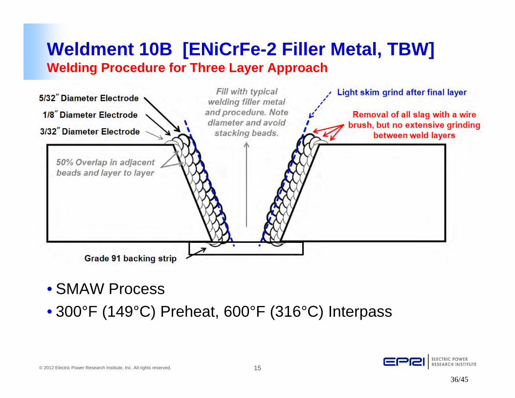
Weldment 10B [ENiCrFe-2 Filler Metal, TBW]Welding Procedure for Three Layer Approach
• SMAW Process
• 300°F (149°C) Preheat, 600°F (316°C) Interpass
36/45

16© 2012 Electric Power Research Institute, Inc. All rights reserved.
Weldment 10B [ENiCrFe-2 Filler Metal, TBW]Welding Assessment – Completed Weldment
37/45

17© 2012 Electric Power Research Institute, Inc. All rights reserved.
Metallographic Assessment
38/45

18© 2012 Electric Power Research Institute, Inc. All rights reserved.
Weldment 10B [ENiCrFe-2, TBW] Hardness Assessment – HAZ Hardness Map
39/45

19© 2012 Electric Power Research Institute, Inc. All rights reserved.
Machined and Tested Creep SamplesCreep testing being conducted at 625°C, 80MPa (~5,000 hr life)
Samples include the entirety of the weld
metal and temperbead layers on either side of
the weld
40/45

20© 2012 Electric Power Research Institute, Inc. All rights reserved.
Modeling
• Modeling in Phase 1 is being conducted to understand procedure issues associated with temperbead welding (i.e. bead overlap, bead placement and electrode size)
• Modeling is focused in identifying the position and influence of overlapping thermal cycles
41/45

21© 2012 Electric Power Research Institute, Inc. All rights reserved.
Phase 2 – Application of Best Option Repair Method(s) to Ex-service Header
• Discussion of methods and extent of excavation
• Weld procedure considerations
• Post repair evaluation of microstructure, damage, etc.
• Development of test matrix and cross-weld creep
42/45

22© 2012 Electric Power Research Institute, Inc. All rights reserved.
Conclusions
• The 20 weldments have been completed and preliminary analysis has been conducted:
– Metallographic
– Hardness testing and mapping
– Statistical analysis of hardness results
• Creep testing is underway of all weldments
– Once completed, results will be presented to NBIC
• Modeling and bead on plate studies have provided insight to “best procedure guidelines” for future Phase 2 work
• Phase 2 to being ~September/October 2012
• Questions or comments?
43/45

23© 2012 Electric Power Research Institute, Inc. All rights reserved.
Contact Information
• John Siefert, Senior Project Engineer
– 704-595-2886, [email protected]
• John Shingledecker, Senior Project Manager
– 704-595-2619, [email protected]
• Jonathan Parker, Senior Project Manager
– 704-595-2791, [email protected]
44/45

24© 2012 Electric Power Research Institute, Inc. All rights reserved.
Together…Shaping the Future of Electricity
45/45

