study on structural behavior characteristics of concrete ... · study on structural behavior...
TRANSCRIPT
Tailor Made Concrete Structures – Walraven & Stoelhorst (eds)© 2008 Taylor & Francis Group, London, ISBN 978-0-415-47535-8
Study on structural behavior characteristics of concrete filled steeltube girder bridges
Won Jong Chin, Jae Yoon Kang, Eun Suk Choi & Jung Woo LeeKorea Institute of Construction Technology, Goyang, Republic of Korea
ABSTRACT: The new bridge system described in this paper uses concrete-filled steel tube girders instead ofconventional girders. A new type of shear connector attached to the tube that is �-shaped perfobond rib providesthe means for developing composite action between the steel tube and the concrete slab deck. Experimentalinvestigations were carried out to examine the flexural behavior of the proposed concrete filled steel tube girder.The experimental investigation consisted of designing and constructing a test specimen and loading it to collapsein bending to understand the ultimate capacity of the system. Test results showed that concrete filled steel tubegirder has good ductility and maintains its strength up to the end of the loading. Results of this investigationdemonstrated the potential for using a concrete filled tube as bridge girder.Additional experimental investigationswere carried out to examine the fatigue behavior of the concrete-filled steel tube girder and revealed also thatthe new type of girder bridge exhibits good fatigue durability.
1 INTRODUCTION
Concrete filled steel tube structures (CFT) is a struc-ture composed by filling a steel tube with concretein which the concrete filling material prevents buck-ling of the steel tube under compression and the steeltube improves the material strength by restrainingthe filling material. Previous studies already demon-strated that the CFT member is developing loadbearing capacity and deformation performance sig-nificantly superior to structural members composedof a unique material. However, most of these stud-ies limited their scope to column members subjectedto compressive forces. Even if Japan, China andEurope started recently to attempt the constructionof bridges using CFT structures, experimental stud-ies are still insufficient to reflect at the most theirbehavioral characteristics as flexural members in thedesign. Accordingly, the current design does not con-sider the increase of load bearing capacity brought bythe composition between the filling inside the steeltube and the deck, and ignores the stiffness of thefilling material in positive moment zone or the com-position with the deck in negative moment zone. Suchdesign is thus inefficient because disregarding theadvantages and behavioral characteristics of the CFTmember. Previous steel girder bridges present pooreconomic efficiency and are subjected to fatigue dueto the numerous welding spots necessary for their
fabrication, are relatively expensive because of theincrease of weight, provoke environmental problemsdue to vibration and noise and, exhibit poor con-structability for concrete girders. The application ofCFT members as bridge girder may represent an alter-native that can remedy such problems to some extent.CFT girder may also contribute to the reduction ofconstruction and maintenance costs, durability andeconomic efficiency of the structure, enhancement ofconstruction quality, and may secure larger clearanceby diminishing the height of the girder. Substantiveand experimental studies shall thus be primarily con-ducted on the behavioral characteristics of compositegirder bridges using CFT girder so as to develop ade-quate design method and promote their practicability.Previous researches implemented numerous tests onreduced-scale prototypes to investigate the flexuralbehavior of CFT member and already demonstratedits remarkable structural effects. This study focuseson the examination of the behavioral characteristicsand fatigue endurance according to the connectionmethod of the CFT girder bridge. Specimens weremanufactured considering various variables affectingthe design, and test results were exploited to derivealternatives for the effective reflection of the remark-able load bearing capacity of the CFT member inthe design. Figure 1 depicts the structural shape andschematic concept of the composite bridge using CFTgirder.
821

2 DEVELOPMENT OF NEW SHEAR KEY
Figure 2 shows the perfobond plate, a newly developedshear key offering constructability, structural safetyand economic efficiency. Korean research teams con-ducted studies on the performance of this new shearkey (Chung, 2004; BBM Korea, KICT, 2004; Lee,2006) and revealed that the proposed �-shaped per-fobond rib exhibit remarkable static ultimate bearingcapacity.This key can be applied effectively for girderssubjected to large horizontal shear forces, especiallyfor composite bridges like CFT girder for which theconstruction of stud shear connector is very difficult.
3 BEHAVIORAL CHARACTERISTICSACCORDING TO THE CONNECTIONMETHOD OF CFT GIRDER BRIDGE
Field or shop welding was mainly applied for theprevious CFT columns or CFT girder bridges. How-ever, field welding is very sensitive to the workingconditions like weather and humidity, and requiresadditional costs due to the involved manpower. Toovercome such problems, Japan already carried outexperimental studies on the bolted connection of thesteel tubes and found out that common bolts canbe applied instead of rounded bolts for steel pipediameters larger than 800 mm. This study examinedthe adoption of bolts instead of welded connectionsthrough flexural tests.
3.1 Connection method of precast CFT members
Specific connection is required to connect precastCFT members without loss of section or stiffness.Figure 3(b) illustrates the selected connection methodto be used for the application of bolts instead of
Figure 1. Structural and sectional shapes of CFT girderbridge.
Figure 2. Proposed type of shear key (�-shapedperforbond).
welded connection. Figure 3(a) presents connection onwhich concrete is poured after fastening of steel rodsand bolt connection with the connection plate. Thissolution offers the remarkable structural advantagethrough the introduction of compressive force by thesteel rods. However, disadvantage resides in the needfor larger space for post-cast concrete within the wholesection due to additional lengths of 2 m required at bothsides of the connection to secure working space for thefastening of steel rods. Figure 3(b) shows the connec-tion poured with concrete immediately after its con-nection by bolts. Here, even if there is no compressiveforce introduced by the steel rods, the shear keys insidethe connection are fastening completely concrete.Since this connection method does not require separatespace for the tensioning works, this methods appears tobe the most optimal for connection in bridges of whichscale does not need compression of the connection.
Various specimens were manufactured to evaluatecomparatively the behavior according to the connec-tion method of steel tubes. These specimens wereD780-W-S, the most common connection throughwelding of the tubes; D780-B-S, bolted connection;D780-BF-S, bolted connection filled with concrete;and, D780-N-S, tubes without connection. The pro-posed connection is illustrated in Figure 5. The speci-mens presented total length of 6 m, external diameter(d) of 780 mm, and thickness (t) of 14 mm so as to bemanufactured with a d/t ratio of 55.7. This ratio fallswithin the range featuring compact section based onprevious studies. All the specimens were filled in theirend sections with length of 1.6 m from the supports.The bolted specimens were manufactured by classify-ing them into filled and non-filled specimens accord-ing to the eventual filling of the central connection.
Filling was performed with ordinary concrete pre-senting strength of 21 MPa. Ordinary concrete withstrength of 27 MPa was poured to manufacture thedeck. The test method shown in Figure 6 proceeded
Figure 3. Connection methods of precast CFT members.
Figure 4. Drawing of the bolted connection.
822
by 3-point loading on the simply supported specimenusing an actuator with capacity of 3,500 kN. Table 1summarizes the connection method of each specimenand their dimensions.
3.2 Behavioral characteristics according to theconnection method of CFT members
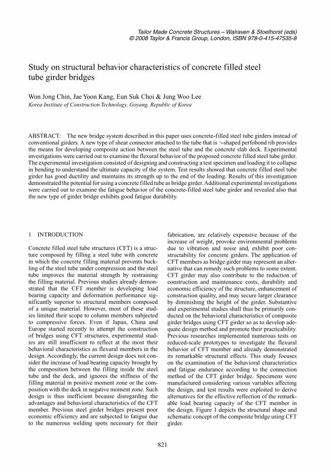
For the no-connection specimen shown in Figure 7(a),the maximum load was 3,450 kN corresponding tothe maximum capacity of the actuator, the maximumdeflection was approximately 37 mm, and the residualdeformation was about 11 mm. The specimen devel-oped resistance all along the loading process withoutclear sign of stiffness degradation.
In the cases of the welded connection and boltedconnection specimens in Figure 7(e), even if the max-imum deflection increased, the specimens exhibitedsufficient serviceability without clear degradation ofthe stiffness.
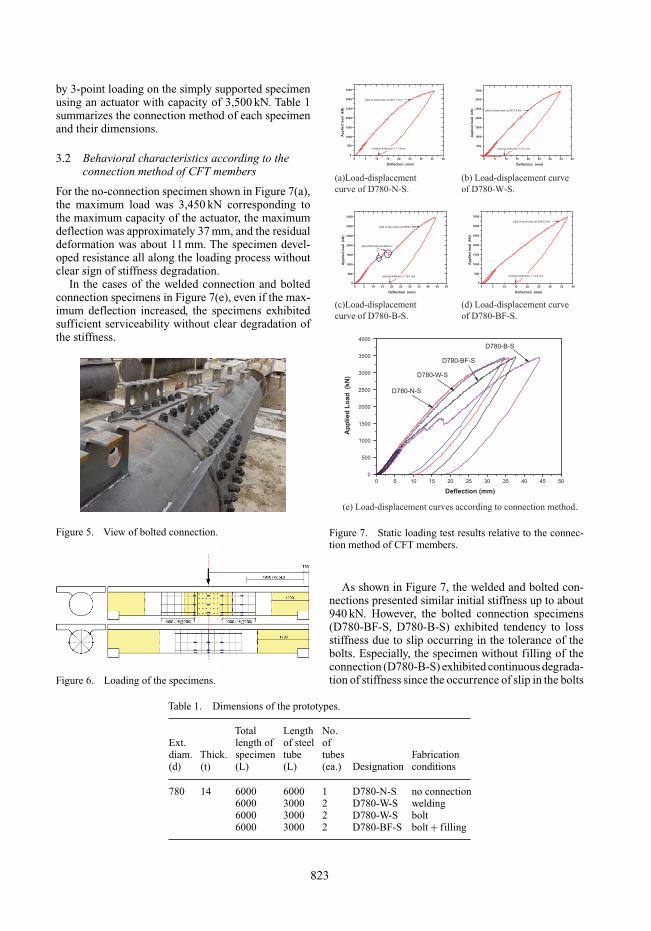
Figure 5. View of bolted connection.
Figure 6. Loading of the specimens.
Table 1. Dimensions of the prototypes.
Total Length No.Ext. length of of steel ofdiam. Thick. specimen tube tubes Fabrication(d) (t) (L) (L) (ea.) Designation conditions
780 14 6000 6000 1 D780-N-S no connection6000 3000 2 D780-W-S welding6000 3000 2 D780-W-S bolt6000 3000 2 D780-BF-S bolt + filling
0 5 10 15 20 25 30 35 40
0
500
1000
1500
2000
2500
3000
3500
yield of steel tube at 2951.1 kN
Ap
plied
lo
ad
(k
N)
Deflection (mm)
residual deflection = 11.0mm
0 5 10 15 20 25 30 35 40
0
500
1000
1500
2000
2500
3000
3500
Ap
pli
ed
lo
ad
(k
N)
Deflection (mm)
yield of steel tube at 2437.8 kN
residual deflection = 9.5 mm
(a)Load-displacement
curve of D780-N-S.
(b) Load-displacement curve
of D780-W-S.
0 5 10 15 20 25 30 35 40 45 50
0
500
1000
1500
2000
2500
3000
3500
slip at the bolt connections
Ap
pli
ed
lo
ad
(k
N)
Deflection (mm)
yield of steel tube at 2962.5 kN
residual deflection = 19.3 mm
0 5 10 15 20 25 30 35 40
0
500
1000
1500
2000
2500
3000
3500
Ap
pli
ed
lo
ad
(k
N)
Deflection (mm)
yield of steel tube at 3240.2 kN
residual deflection = 14.8 mm
(d) Load-displacement curve
of D780-BF-S.
0 5 10 15 20 25 30 35 40 45 50
0
500
1000
1500
2000
2500
3000
3500
4000
D780-B-S
D780-BF-S
D780-W-S
Ap
pli
ed
Lo
ad
(k
N)
Deflection (mm)
D780-N-S
(e) Load-displacement curves according to connection method.
(c)Load-displacement
curve of D780-B-S.
Figure 7. Static loading test results relative to the connec-tion method of CFT members.
As shown in Figure 7, the welded and bolted con-nections presented similar initial stiffness up to about940 kN. However, the bolted connection specimens(D780-BF-S, D780-B-S) exhibited tendency to lossstiffness due to slip occurring in the tolerance of thebolts. Especially, the specimen without filling of theconnection (D780-B-S) exhibited continuous degrada-tion of stiffness since the occurrence of slip in the bolts
823

Figure 8. View of tests on no-connection specimen andbolted connection specimen.
Figure 9. Rebar arrangement of deck.
according to the increase of load. On the other hand,the specimen of which connection was filled (D780-BF-S) presented a tendency to resist against the lossof stiffness through strengthening effect of the fillingmaterial.
Accordingly, when bolted connection is to beapplied in actual bridge, filling of the bolted connec-tion appears to prevent the loss of serviceability whileexhibiting initial stiffness and load bearing capacitysimilar to non connected steel tubes.
Figure 10. Slip of gusset plate in bolt connection.
4 EVALUATION OF FATIGUE ENDURANCEOF CFT GIRDER BRIDGE
Fatigue loading tests were conducted on CFT girder-deck composite sections to examine the fatigue behav-ior of the CFT girder bridge. The loaded specimenspresented identical dimensions and properties to theones used in the static loading for the comparison of theconnection methods. Comparative analysis was per-formed for the fatigue bearing capacity according tothe connection method as well as for the fatigue behav-ior of the CFT girder-deck sections. Loading of 250 kNwas set up considering the impact factor (i = 0.3) forthe rear wheel load of DB-24 service load. Loadingwas applied from 50 kN to 300 kN for fatigue test pur-pose (stress ratio of about 0.166). For the evaluationof the load bearing capacity according to the load-ing cycles, the displacement of the actuator and thedeflection at the bottom of the center of the tube byapplying a static load of 300 kN at determined loadingcycles, and the residual displacement of the actuatorwas also measured at about 5 kN after removal of thestatic load. Loading was applied using MTS actuatorswith capacity of 500 kN and 1,000 kN. The velocity offatigue loading was fixed to 3 Hz.
From the fatigue test results, clear tendency of themaximum displacement to increase was not observeduntil 2 million loading cycles regardless of the con-nection method and in any specimen, and fatiguedamage was not detected at service load level. Themaximum deflection at each loading cycle remainedbelow 2.5 mm, showing that the deflection is extremelysmall at service load level. After removal of the load,the residual deflection also exhibited extremely smallvalue below 1 mm, revealing that fatigue damage didnot occur anyway. An observation of the average max-imum displacement of each specimen in the followinggraphs reveals that the maximum deflections showedpractically no variation according to the specimens thatabout 2.24 mm for the no-connection specimen, about2.74 mm for the welded specimen, about 2.40 mm for
824

10000 100000 10000002.05
2.10
2.15
2.20
2.25
2.30
2.35
2.40
Max
. Def
lect
ion
(m
m)
Cycles
average deflection = 2.24mm
Figure 11. Maximum deflection of specimen D780-N-Faccording to loading cycles.
10000 100000 10000002.40
2.55
2.70
2.85
3.00
3.15
Max
. Def
lect
ion
(m
m)
Cycles
average deflection = 2.74mm
Figure 12. Maximum deflection of specimen D780-W-Faccording to loading cycles.
10000 100000 10000002.20
2.25
2.30
2.35
2.40
2.45
2.50
2.55
Max
. Def
lect
ion
(m
m)
Cycles
average deflection = 2.40mm
Figure 13. Maximum deflection of specimen D780-B-Faccording to loading cycles.
10000 100000 10000002.20
2.25
2.30
2.35
2.40
2.45
2.50
2.55
Max
. Def
lect
ion
(m
m)
Cycles
average deflection = 2.41mm
Figure 14. Maximum deflection of specimen D780-BF-Faccording to loading cycles.
the bolted specimen and, about 2.41 mm for the boltedand filled specimen.
5 CONCLUSIONS
Flexural loading tests were conducted to evaluate thebehavioral characteristics and load bearing capacityaccording to the connection method of CFT girders.Test results revealed that the non-connected CFT mem-bers and the welded and bolted connections exhibitedsimilar performance in terms of initial stiffness andload bearing capacity. Regard to ductility, the methodusing bolt connection appeared to have superior behav-ior. Even if the welded connection behaved similarly tothe non-connected CFT members, necessity remainsto solve the disadvantages in time and cost consump-tion produced by field welding. The method adoptingbolted connection being an alternative remedying suchproblems exhibited remarkable load resistance andstiffness together with improvement of serviceabilityin terms of vibration and noise of the CFT mem-bers through the filling of the connection. In addition,increase of the ductility of the CFT members couldalso be obtained by this method.
Accordingly, for the application of CFT membersfor long-span bridges and, 2-span or 3-span continuousbridges, the adoption of bolted connection appears tobe more effective than field welding in view of the timeand economic disadvantages that can be produced bythe latter.
Moreover, fatigue tests were also performed to eval-uate the fatigue performance of the CFT girder bridge.Results showed no clear increase of the maximum dis-placement until 2 million loading cycles in all thespecimens and regardless of the connection method.Fatigue damage was also not detected at service loadlevel. Therefore, the CFT girder bridge can be seen
825
to also have remarkable behavioral characteristics interms of fatigue endurance.
ACKNOWLDEGEMENTS
This work is part of the “Development of compositebridge structures using CFT girders”, a R&D projectof the Ministry of Construction and Transportation.The authors acknowledge for the support.
REFERENCES
Chin, W.J., Kang, J.Y., Choi, E.S., Lee, J.W., and Kim, B.S.2007. Experimental Study on Flexural Behavior of Con-crete Filled Steel Tube Girder Bridges, IABSE Symposium2007 Weimar, Vol. 93: 458–459.
Leonhardt, F., Andrae, W., and Harre, W. 1987. New advan-tageous shear connector with high fatigue strength forcomposite structures (Neues vorteilhaftes Verbundmit-tel fur Stahlverbundtragwerke mit hoher Danerfestigkeit),Beton-und Stahlbetonbau, Vol. 12: 325–331.
Hosaka, T., Nakamura, S., Umehara, R., and Nishiumi, K.1997. Design and experiments on a new railway bridgesystem using concrete filled steel pipes. InternationalConference of IABSE in Innsbruck.
Nakamura, S. 2000. New Structural forms for steel/concretecomposite bridges. Structural Engineering International,Journal of IABSE. Vol. 10(1): 45–50.
Matsumura, T., Hosaka, T., Hiraoka, C., and Nichiumi. K.2003. Practical application of composite bridge forShinkansen using CFT. IABSE Symposium in Antwerp.Vol. 87: 136–137.
Nakamura, S., Hosaka, T., and Nishiumi, K. 2004. Bendingbehavior of steel pipe girders filled with ultralight mortar,Journal of Bridge Engineering. Vol. 9, No.3: 297–303.
826