study of the nozzle diameter influence in the fluid
TRANSCRIPT

IV Journeys in Multiphase Flows (JEM 2015) March 23-27, 2015, Campinas, SP, Brazil
Copyright © 2015 by ABCM Paper ID: JEM-2015-0051
STUDY OF THE NOZZLE DIAMETER INFLUENCE IN THE FLUID
DYNAMICS OF A CYLINDRICAL HYDROCYCLONE SEPARATOR
Hans E. M. Ninahuanca UTFPR, Av. Sete de Setembro 3165, Curitiba-PR-Brazil
Henrique Stel UTFPR, Av. Sete de Setembro 3165, Curitiba-PR-Brazil
Cesar Ofuchi UTFPR, Av. Sete de Setembro 3165, Curitiba-PR-Brazil
Rigoberto E. M. Morales UTFPR, Av. Sete de Setembro 3165, Curitiba-PR-Brazil
Flávio Neves UTFPR, Av. Sete de Setembro 3165, Curitiba-PR-Brazil
Abstract. This work presents a numerical study on the flow inside a gas-liquid cylindrical hydrocyclone separator.
This equipment operates with a free-surface liquid film flow, which is a combination of a centrifugal and a
gravitational movement originated by a tangential nozzle. Fully developed flow results taken at the outlet of the
separator depend on two dimensionless numbers, the film Reynolds number and the Froude number. However,
numerical results indicate that the dynamics of the flow in regions close to the inlet of the device depend also on the
ratio between the nozzle diameter and the chamber diameter. This paper will be focused on investigating this new
dimensionless number using both CFD and a mechanistic model. Software ANSYS-CFX was employed in the CFD
analysis to simulate a wide range of operating conditions regarding the three dimensionless numbers mentioned. The
results of the simulations provided basis for the development of a compact mechanistic model for calculating velocity
components, film thickness and other variables. This model was derived by analyzing the motion of a fluid element and
then by including additional terms that represent the sudden expansion of the flow at the inlet of the cylindrical
chamber. Then, the terms included and some model coefficients were calibrated using the numerical results. The
outcomes of this work can be used to predict the flow dynamics in a hydrocyclone, which is a fundamental step for
more complex evaluations such as estimating the separation efficiency and developing new constructive concepts for
the equipment.
Keywords: hydrocyclone separator, nozzle diameter influence, numerical simulation, mechanistic model, flow
dynamics.
1. INTRODUCTION
In the petroleum industry, crude oil is usually associated with gas and reservoir water. Separating this kind of
mixture into their distinct phases still in the wellhead brings several advantages to the process. Most of them are related
to typical operational problems of multiphase flows like intermittency, hydrate formation, low centrifugal pump
efficiency, difficulties in flow measurements and poor reservoir management.
Some petroleum companies have already used centrifugal separators for this purpose, such as the Gas-Liquid
Cylindrical Cyclones (GLCC’s). The present work focuses on an alternative based on this technology, the Vertical
Annular Separation and Pumping System-VASPS, patented by United Kingdom’s British Petroleum (BP) in 1988. In
spite of its compact design, ease of operation and supposedly high efficiency, the VASPS separator is not widely used
in the petroleum industry. Prediction of the flow dynamics inside the separator’s expansion chamber is still inaccurate
and its actual separating efficiency for several operating conditions is quite uncertain (Rosa, 2001). Moreover, since its
concept is not widely spread, it is even unknown if the actual constructive design is close to an optimal one. The
phenomenon of the flow separation in this equipment is subject of a combination of both centrifugal and gravitational
forces acting in a thin liquid film whose dynamics lacks a reliable modeling, thus making it difficult to design new
systems and improve existing ones given the operational conditions. Uncertainties regarding the actual multiphase flow

Hans E.M. Ninahuanca, Henrique Stel and Cesar Ofuchi Study of the Nozzle Diameter Influence in the Fluid Dynamics of a Cylindrical Hydrocyclone Separator
2
pattern that enters this separator and the influence of the liquid viscosity in the process adds more complexity to the
task.
The flow dynamics in the expansion chamber is shown in Fig. 1. The tangential inflow generates a strong
centrifugal field which forms a liquid film over the chamber wall. The separation process is based on two mechanisms,
the first related to the formation of a thin liquid film that naturally separates large gas portions, and the second related to
the strong centrifugal field which increases the buoyancy force caused by the liquid over the gaseous phase.
Levich (1962) published one of the earliest works on the flow of thin liquid layers on a vertical plane wall, seeking
to describe the flow regimes as a function of the Reynolds number in the film, Re . Malamatenios et al. (1994)
demonstrated that the wall shear stress is the sole parameter involved in the balance of the gravitational forces acting on
the film; he also showed that the liquid film thickness tends to a minimum, which once reached, remains constant.
Figure 1. Illustration of the flow dynamics in the expansion chamber (Stel et al., 2012).
Morandin (1999) demonstrated that the variables in this kind of separator are very well correlated by two
dimensionless parameters: the final film Reynolds number, fRe , and the final squared Froude number, 2
QfFr , which
are respectively given by:
2
L
f
QRe
R (1)
2
22
L
Qf
Q
RFr
gR (2)
where LQ is volumetric flow at the inlet, R is the chamber radius, is the kinematic viscosity and g is the gravity.
Morandin (1999) proposed a mathematical model to predict the liquid flow behavior. His model assumes the flow as
axisymmetric, a condition that arises when the centrifugal forces tend to zero. However, the flow inside the separator is
characterized by high velocities and subtle variations in their components. Therefore, his model is a mere idealization of
the actual phenomenon. Sant’anna (2010) carried out numerical simulations of flows in the expansion chamber. He
concluded that, for low inlet gas void fractions, the flow behavior is dominated by the liquid motion. Ofuchi (2012)
carried out a numerical study aimed to quantify variables at the bottom of the expansion chamber, while not
investigating properties through the whole flow field.
The behavior of the liquid in an expansion chamber is still an open subject that requires further investigation. A
better understanding of the flow dynamics in a separator strongly depends upon studies on local liquid velocities. The
gist of the present work is to investigate the tangential and axial liquid velocity components focused on the influence of
the nozzle diameter and the chamber diameter of the expansion chamber. This will be accomplished by means of a

IV Journeys in Multiphase Flows (JEM 2015)
numerical study based on computational fluid dynamics and a mechanistic model aimed to predict the flow behavior for
several operating conditions.
2. MATHEMATICAL MODEL
This section presents two mathematical models, the first is the two-fluid model used in the numerical solution and
the second is the algebraic model developed in this work.
Two-fluid model
The two-fluid model developed by Ishii and Mishima (2005) is based on a stationary, Eulerian frame of reference
and on averaged mass and momentum balances where the phases are treated as continuous and interpenetrating. This
model is based on the following equations:
ˆ
k k
k k k kt
v Γ (3)
ˆ
ˆˆ ˆ
Tk k k
k k k k k k k k k k k k kpt
vv v τ τ g M (4)
where k relates to a phase, k is the volumetric fraction of each phase, k
is the phase density, ˆkv is the mass-
averaged phase velocity, kΓ is the mass transfer, kM is the momentum transfer, kp is the pressure, ˆ
kg is the gravity,
kτ is the viscous stress tensor and Tkτ is the Reynolds stress tensor.
A variety of turbulence models are available, in this paper the Reynolds stress was modeled using the shear stress
transport (SST) model, which combines the model for boundary layers with the model for regions outside
the boundary layer (1994). SST model automatically blend wall functions to a low-Reynolds formulation. Further
details are provided in Esch and Menter (2003).
Algebraic modelling
The present work proposes a computationally inexpensive method for solving the velocity field in an expansion
chamber. The model was created by analyzing the motion of a fluid element subjected to a gravitational and centrifugal
field within the expansion chamber and then by including additional terms that represent the sudden expansion of the
flow at the inlet. The velocity components of the flow along the expansion chamber are therefore obtained. The forces
acting on a fluid element at any specific time are the wall shear force, wF , the fluid element mass, mg , and the force
due to the sudden expansion of the flow at the inlet in the tangential and axial directions, etF and
ezF respectively.
Figure 2. Forces acting on a fluid element at the wall of the expansion chamber.
where V is the mean velocity of the flow at the streamline, the tangential and axial components of velocity are
respectively tV and
zV , is the film thickness,elA is the area of the fluid element and is the angle between the
streamline and the horizontal line.
k k

Hans E.M. Ninahuanca, Henrique Stel and Cesar Ofuchi Study of the Nozzle Diameter Influence in the Fluid Dynamics of a Cylindrical Hydrocyclone Separator
4
Applying Newton’s Second Law to the element depicted in Figure 2, yields:
cosw et
Vtm F F
t
(5)
w ez
Vzm mg F sen F
t
(6)
These equations govern the dynamics of the fluid element from a Lagrangian reference. The forces due to the
sudden expansion arise due to the action of centrifugal force on the liquid film, which accelerates the flow in the axial
direction and as response the flow decelerates in the tangential direction. Figure 3 and Figure 4 show the fluid element
dynamics according to the numerical results and the results of a model that does not consider the influence of the
sudden expansion.
Figure 3. Effect of the sudden expansion over the axial velocity.
Figure 4. Effect of the sudden expansion over the tangential velocity.
Flow dynamics under these conditions has not yet been studied, therefore this paper proposes an approach to
analyze the axial and tangential forces of the sudden expansion. For this purpose, a function was created, which
depends on the local centrifugal force and the film thickness. It was assumed that the axial and tangential force
components are proportional to the function so that:
2
/ 2
t cr
chamber final final
mV
(7)
ez zF K (8)
0,0
0,5
1,0
1,5
2,0
2,5
3,0
3,5
0,00 0,25 0,50 0,75 1,00 1,25 1,50
Vz
(m/s
)
Z (m)
With sudden expansion.
Without sudden expansion.
0
5
10
15
20
0 0,1 0,2 0,3 0,4 0,5 0,6
Vt
(m/s
)
t (s)
With sudden expansion.
Without sudden expansion
ezF
etF

IV Journeys in Multiphase Flows (JEM 2015)
et tF K (9)
where, zK and
tK are coefficients calibrated with numerical results, is the local film thickness, cr is the critical
film thickness and f is the final film thickness.
The wall force, wF , depends of the flow regime and is shown below for each case. The wall force for turbulent
regime, Eq. (6), is derived from Darcy’s Law and from Blasius’ Power Law as described by White [10]. The wall force
for laminar regime, Eq. (7), is derived assuming a parabolic flow profile. Finally, for the case of transition regime, Eq.
(8), the wall force is obtained with a weighting function, fp , between the turbulent and laminar conditions.
0.75 0.25 1.75 0.250.24
8 elw Turbulent
F V A (10)
min
3
el
w La ar
VAF (11)
min1
w Transition w La ar w TurbulentF F fp F fp (12)
The weighting function was tested from the numerical results and has been proposed the following equation:
2
Re Re
Re Re
TT
TT TL
fp
(13)
where ReTT
is the value of the Reynolds corresponding to the limit of Turbulent-Transient regimes, it is equal to 1500
according to Levich (1962). ReTL
is the limit of Transient-Laminar regimes and based on the numerical results of this
work was obtained an approximate value of 500.
According to the formulation presented in this section, the calculation of the velocities depend on the behavior of
the film thickness and the coefficients zK and
tK . The numerical results section presents the formulation of these
values because they are calibrated according to the behavior of those results and then the formulation will be completed.
3. NUMERICAL MODEL
This work is focused on the dynamics of the liquid phase and for this reason single-phase liquid flow at the inlet is
simulated. To represent the free surface, free regions of liquid are filled with gas and flow fields for liquid and gas
phases must be calculated. In this work, the computational package ANSYS-CFX is used, which implements an Euler-
Euler formulation as described by ANSYS (2012).
The free surface is resolved though a compressive discretization scheme, which is a numerical procedure applied to
the advection term of the volume fraction equation and is regarded as a good choice for obtaining a sharp interface, as
detailed by Zwart et al. (2008).
Computational grid
Figure 5 depicts the geometry of the cylindrical cyclone considered. The numerical domain was created disregarding
the central region of the expansion chamber where there is no liquid flow, this was done to economize on mesh
elements in this region because it has no influence on the dynamics of liquid, hence it does not need to be resolved.

Hans E.M. Ninahuanca, Henrique Stel and Cesar Ofuchi Study of the Nozzle Diameter Influence in the Fluid Dynamics of a Cylindrical Hydrocyclone Separator
6
Figure 5. Geometry of the numerical domain.
Figure 6 shows the structured numerical grid used in the numerical simulations. Higher mesh densities around the
nozzle-chamber transition and at the cylinder wall were used to provide a good representation of the free surface
interface. A mesh sensibility test revealed that a grid with around 800,000 elements can reproduce mesh-independent
results in this study.
(a) Higher mesh densities at the chamber wall.
(b) Higher mesh densities at the nozzle-chamber transition.
Figure 6. Numerical mesh.
4. NUMERICAL RESULTS
In this section is studied the behavior of the velocity components and the film thickness in function of streamlines.
Mean streamline
The methodology for studying the dynamics of flow in the expansion chamber will be based on the study of the
velocity components along streamlines. Figure 7 shows an example of how the streamlines follow different trajectories.
Analyzes of each of them separately is very complicated and it depends on the refinement of the computational grid
used and the numerical methodology used for tracking. In addition to those complications, the study of individual
streamlines does not offer global information of the separator operation. To make a proper study of the trajectory and
dynamics of flow, this paper proposes the calculation of a mean streamline which represents the behavior of all
streamlines.

IV Journeys in Multiphase Flows (JEM 2015)
Figure 7. Illustration of individual streamlines and the mean streamline.
Figure 8 and Figure 9 shows numerical results of the tangential and axial velocity for each streamline shown in
Figure 7.
Figure 8. Tangential velocity of each streamline.
Figure 9. Axial velocity of each streamline.
Figure 8 shows that the magnitude of the tangential velocity has a rapid decrease near the inlet. This happens due to
the spreading of liquid in the expansion chamber wall. It can also be seen that the tangential velocity has little
dependence on the streamline analyzed. Similar tests were performed for the whole range of operating conditions
studied and the same trends for this component were found. Therefore, in this paper, information for the tangential
velocity of the mean streamline will be obtained directly from an individual streamline.
0
3
6
9
12
15
18
0 0,1 0,2 0,3 0,4 0,5 0,6
Vt
(m/s
)
t (s)
S1
S2
S3
S4
0,0
0,5
1,0
1,5
2,0
2,5
3,0
0 0,1 0,2 0,3 0,4 0,5 0,6
Vz
(m/s
)
t (s)
S1
S2
S3
S4

Hans E.M. Ninahuanca, Henrique Stel and Cesar Ofuchi Study of the Nozzle Diameter Influence in the Fluid Dynamics of a Cylindrical Hydrocyclone Separator
8
_ _t t selected streamlineV V (14)
where tV is the tangential velocity of the mean streamline,
_ _t selected streamlineV is the tangential velocity of an individual
streamline and can be selected anywhere provided that the streamline goes downwards, since part of the flow is spread
upwards and this phenomenon is not modeled. In order to achieve this, the selected streamline was taken slightly off the
nozzle center.
Figure 9 shows that the magnitude of the axial velocity has a rapid increase near the inlet due to the spreading of the
liquid in the expansion chamber. The axial acceleration corresponds to the tangential deceleration in the same region. In
addition, it can be seen that the axial velocity depends strongly on the selected streamline, indicating that for a proper
study of this velocity component it is necessary to consider a mean streamline to find a representative behavior of this
component. In this work, it was assumed that the axial velocity is axisymmetric in the expansion chamber, which allows
calculating axial velocity as a function of position on the axis Z according to Eq. (15).
1
z
z z
z A
V V n dAA
(15)
where zV is the axial velocity of the mean streamline,
zA is the area of the film thickness at general position in the Z
axis , V is the velocity field in the plane zA , n is the unit vector in the direction of the Z axis and R is the chamber
radius.
Following equations (14) and (15), mean streamline paths for different conditions of mass flow rate are shown in
Figure 10 and Figure 11 below.
Figure 11 also shows a reference position designated as 1Z , which for high flow rates corresponds to the maximum
axial velocity. This position will be important to study the behavior of the film thickness as will be presented in the
algebraic model calibration section.
Figure 10. Tangential velocity at the mean streamline.
Figure 11. Axial velocity at the mean streamline.
IV Journeys in Multiphase Flows (JEM 2015)
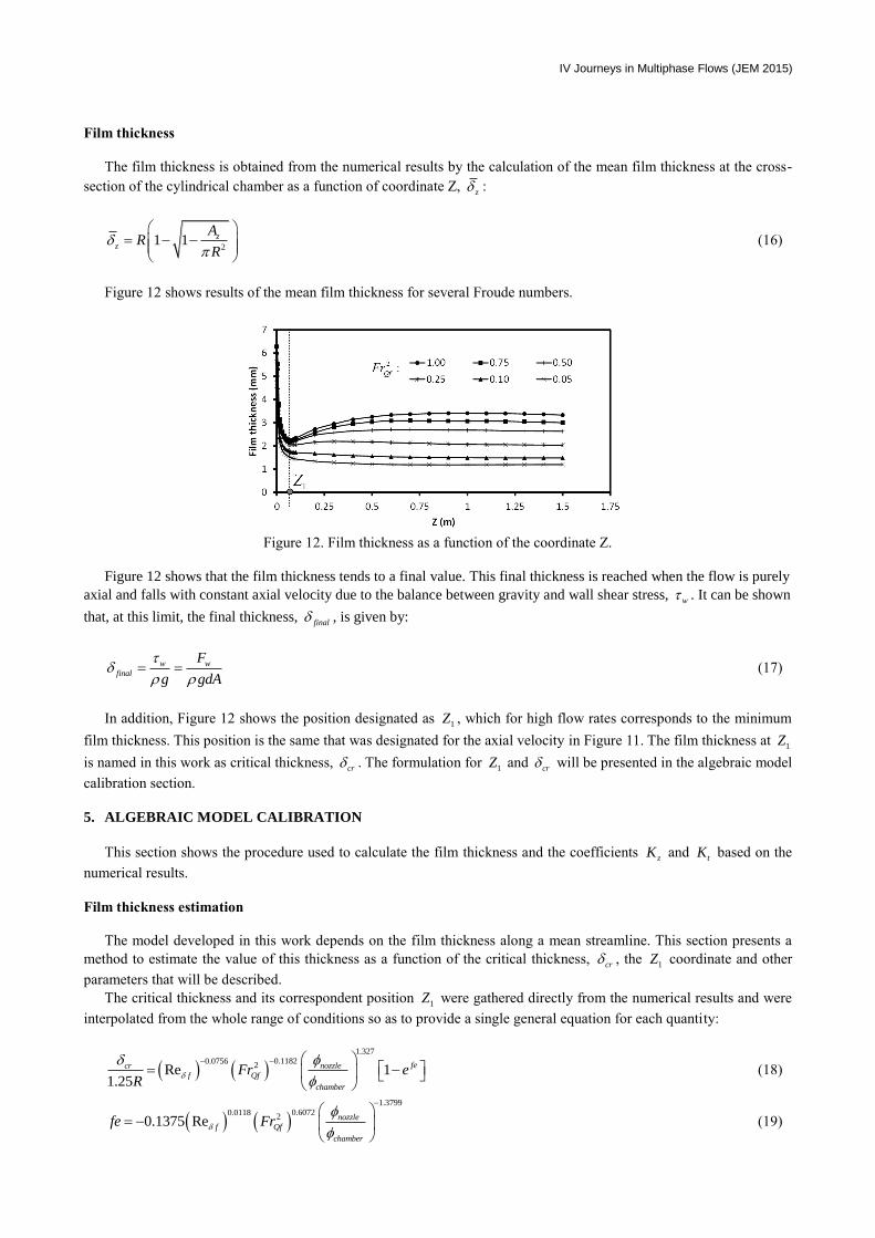
Film thickness
The film thickness is obtained from the numerical results by the calculation of the mean film thickness at the cross-
section of the cylindrical chamber as a function of coordinate Z, z :
21 1 z
z
AR
R
(16)
Figure 12 shows results of the mean film thickness for several Froude numbers.
Figure 12. Film thickness as a function of the coordinate Z.
Figure 12 shows that the film thickness tends to a final value. This final thickness is reached when the flow is purely
axial and falls with constant axial velocity due to the balance between gravity and wall shear stress, w . It can be shown
that, at this limit, the final thickness, final , is given by:
w w
final
F
g gdA
(17)
In addition, Figure 12 shows the position designated as 1Z , which for high flow rates corresponds to the minimum
film thickness. This position is the same that was designated for the axial velocity in Figure 11. The film thickness at 1Z
is named in this work as critical thickness, cr . The formulation for
1Z and cr will be presented in the algebraic model
calibration section.
5. ALGEBRAIC MODEL CALIBRATION
This section shows the procedure used to calculate the film thickness and the coefficients zK and
tK based on the
numerical results.
Film thickness estimation
The model developed in this work depends on the film thickness along a mean streamline. This section presents a
method to estimate the value of this thickness as a function of the critical thickness, cr , the 1Z coordinate and other
parameters that will be described.
The critical thickness and its correspondent position 1Z were gathered directly from the numerical results and were
interpolated from the whole range of conditions so as to provide a single general equation for each quantity:
1.327
0.11820.07562Re 1
1.25
fecr nozzle
f Qf
chamber
Fr eR
(18)
1.3799
0.60720.011820.1375 Re nozzle
f Qf
chamber
fe Fr
(19)

Hans E.M. Ninahuanca, Henrique Stel and Cesar Ofuchi Study of the Nozzle Diameter Influence in the Fluid Dynamics of a Cylindrical Hydrocyclone Separator
10
1 9.33332
nozzleZ
(20)
Equation (18) evaluates the critical thickness depending on the flow conditions and the separator geometry.
Equation (20) shows that the 1Z position only depends on the nozzle diameter, which means that it is a result of the
flow intensity at the nozzle-chamber transition only.
To formulate the film thickness along the mean streamline, it should be stressed that there are some differences
between what is to be considered in the algebraic model and the film thickness obtained directly from the numerical
results. Figure 13 shows these differences, where the solid curve is a numerical solution and the dashed line is the
estimation of the film thickness along the mean streamline.
Figure 13. Estimation of the film thickness along the mean streamline.
Figure 13 shows a big difference between the two curves near the entrance because the film thickness does not have
an axisymmetric behavior in this region. The estimation of the thickness is composed of three straight lines segments
denoted as L1, L2 and L3. Each segment is described below:
For the L1 segment, it is assumed that, at the nozzle, the estimated film thickness is equal to the nozzle diameter,
and then at the 1Z position it reaches the critical thickness in order to match with the numerical result.
For the L2 segment, a new position 2Z was designated, where it is considered that the film thickness reaches its
final value. It was assumed that 2Z position can be evaluated by Eq. (21):
2 1 final crZ Z m (21)
Comparisons for the whole range of conditions studied indicate that 400m provides good agreement with the
numerical results.
For the L3 segment, is considered that the estimated film thickness should be equal to the final thickness.
According to these assumptions, the estimation of the film thickness along the mean streamline, , would have the
following equation:
1
1
1
1
1 2
2 1
2
, 0
,
,
cr nozzle cr
cr final cr
final
Z ZZ Z
Z
Z ZZ Z Z
Z Z
Z Z
(22)
Equation (22) is used to complete the formulation of the model and thus to calculate the velocity components of the
flow at the mean streamline. After obtaining these velocities, it is possible to make a new calculation with greater

IV Journeys in Multiphase Flows (JEM 2015)
accuracy for this thickness. Equation (23) below can be used to perform this further recalculation, which is based on the
continuity equation:
_z final final
z
V
V
(23)
Coefficients zK and
tK
The coefficients zK and
tK were obtained from the numerical results. Their behavior respect to 2
QFr and Re are
shown in Figs. 14 and 15, respectively.
Figure 14. Behavior of the coefficient
zK respect to 2
QfFr and fRe , for all the range of conditions studied.
Figure 15. Behavior of the coefficient tK respect to
2
QfFr and fRe , for all the range of conditions studied.
Figures 14 and 15 show that the coefficients zK and
tK have different behaviors for turbulent, transition and
laminar regimes, therefore separate formulations must be proposed depending on the regime. Similar studies for
different values of the nozzle diameter were also performed and this parameter was also included into the model. The
model was also tested for bigger separators and it was verified that these coefficients holds in a dimensionless basis.
The following equations were obtained:
For turbulent regime ( 1500fRe ):
0.42430.10042
34.5669 10f Qf
z
nozzle chamber
Re FrK
(24)
0.35210.31632
26.8495 10f Qf
t
nozzle chamber
Re FrK
(25)

Hans E.M. Ninahuanca, Henrique Stel and Cesar Ofuchi Study of the Nozzle Diameter Influence in the Fluid Dynamics of a Cylindrical Hydrocyclone Separator
12
For transient and laminar regime ( 1500fRe ):
0.42432 2
70.0033 1.7 15818
1.05655 10
f f Qf
z
nozzle chamber
Re Re FrK (26)
0.35212 2
70.0036 11.04 37193
1.0782 10
f f Qf
t
nozzle chamber
Re Re FrK (27)
With the formulation proposed, the model developed in this study becomes completely independent of additional
data in order to solve the flow dynamics over the mean streamline. This model can be used to solve cylindrical
separators that are based in the thin liquid film formation, such as the VASPS mechanism. The model has the following
limitations respect to the separator geometry and flow conditions:
This model must be used to cylindrical cyclonic separators with cylindrical, tangential and horizontal nozzle.
For 0.085nozzle chamber , Re 10000f and 2 1QfFr , the flow intensity is very strong and generates very high
liquid elevations upwards over the chamber wall, exceeding the numerical domain. This situation was not yet
extensively studied and tested in this work, since the behavior of the critical thickness is different from the usual
range and might not be well represented by the formulation presented in Eq. (18)
For 0.15nozzle chamber , 500fRe and 2 0.1QfFr , the flow intensity is very weak and is not sufficient to form a
continuous film over the chamber wall. These cases are not of interest to the application of this type of separator,
thus were not deeply studied, but the model solutions seem to offer good results even in these conditions.
6. MODEL RESULTS
This section presents the model results compared with numerical results. The results will be analyzed depending on
the nozzle diameter. Analysis of this section correspond to 5000fRe , 2 0.5QfFr , chamber142 mm and nozzle
12,
15, 18 e 21 mm.
Axial velocity
Figure 16 shows results for the axial velocity. The curves are shown only to the axial position Z = 500 mm to
improve the display of the results near the nozzle, because for remote nozzle regions all curves converge in the same
final value defined by fRe and 2
QfFr parameters (Morandin 1999), in other words, the final axial velocity does not
depend on nozzle diameter.
Figure 16. Numerical and model results for the axial velocity at the mean streamline.

IV Journeys in Multiphase Flows (JEM 2015)
Figure 16 shows that the flow gets higher axial velocity near to the inlet when the nozzle diameter is smaller,
because the higher flow velocity at the inlet increases the centrifugal force on the flow and therefore also increase the
sudden expansion forces.
The final axial velocity is reached with accuracy and this indicates that the formulation used for the shear stress in
the model agrees with the SST model from the numerical results. The point of maximum axial velocity is well
represented by the formulation developed for the sudden force terms, where the curves show that the model lose
accuracy near the inlet when the nozzle diameter is small. This is because for smaller diameters of the range studied, the
critical thickness behaves differently and the formulation presented for its calculation, Eq. (18), begins to provide
inaccurate information. The model calculates the critical thickness and provide great results within the studied limits:
0,085 0,148 nozzle chamber .
Tangential velocity
Figure 17 shows results for the tangential velocity. It can be noted that the initial tangential velocity at the nozzle
can be well estimated as the average flow velocity in the inlet pipe. In addition, one can note that the gradual decay of
the tangential velocity along the chamber is in good agreement with the numerical results, which shows once again that
the expressions used for the wall shear stress in the model are fairly accurate for the purpose of this formulation.
Figure 17. Numerical and model results for the tangential velocity at the mean streamline.
Streamline angle
Figure 18 shows results for the angle of the mean streamline throughout the separator. These results are directly
dependent on the axial and tangential velocities, and are well captured following the good agreement observed in Figs.
16 and 17. It can be observed that the mean streamline angle would tend to a final value of 90 degrees if the chamber
was long enough in order to the tangential velocity to vanish.
Figure 18. Numerical and model results for the angle of the mean streamline.

Hans E.M. Ninahuanca, Henrique Stel and Cesar Ofuchi Study of the Nozzle Diameter Influence in the Fluid Dynamics of a Cylindrical Hydrocyclone Separator
14
Figure 18 shows that with a larger diameter nozzle, the flow along the separator tends more rapidly to the final value
of 90 degrees, that is, the flow lose the centrifugal field in a shorter time because a the liquid enters to the separator with
lower tangential velocity. Results show that larger nozzle diameter increases the inaccuracy of the model results away
from the inlet. This is because for larger nozzle diameters, the flow enters with lower rate to the expansion chamber and
its motion becomes unstable where the numerical results show fluctuations as seen in Figure 18 for the nozzle of 21mm.
Film Thickness
Figure 19 shows results for the mean film thickness. It can be seen that the recalculation approach presented in Eq.
(23) provides results with better agreement with the numerical results than the film thickness estimation used in the first
calculations.
Figure 19. Numerical and model results for the film thickness.
Figure 19 shows that the model provides good results for calculating the film thickness where the accuracy of the
model does not depend on the diameter of the nozzle.
The developed model was compared with other 240 numerical solutions of the following range:
500 Re 10000f , 20.05 1QfFr and 0.085 0.15nozzle chamber , which showed good agreement with the
numerical results as shown in Figs. 16-19, but were not shown here for sake of brevity.
7. CONCLUSIONS
A numerical study on the flow inside an expansion chamber of a cyclone separator has been presented. The goal of
the present work was to develop an algebraic model to predict the velocity field of the liquid inside this equipment. The
results showed that the behavior of the velocity in the mean streamline can be described by study of the forces acting on
a fluid element.
The formulation proposed in this work uses coefficients and source terms to include the influence of the sudden
expansion of the flow at the nozzle, which proved to be important to accurately describe the flow field throughout the
cylindrical chamber for the whole range of operating conditions for which this equipment is supposed to handle. In
addition, it was shown that the initial guess assumed for the film thickness allows for a fast and accurate convergence of
the solution.
The formulation employed to calculate the wall shear stress yielded results consistent to the physical principles
involved in the problem. It was observed that the final velocity in the axial direction obtained with the model converges
to the value calculated numerically. Results show that the final axial velocity only depends on the fRe and 2
QfFr
conditions and does not depend on the nozzle diameter.
The velocity components obtained with the proposed model were found to be in good agreement with the numerical
simulations. Therefore, accurate results can be expected for the absolute velocity, the angle of the mean streamline and
the residence time of the fluid inside the expansion chamber.
The model presented in this paper allows future analytical studies on the dynamics of gas bubbles moving inside the
resolved liquid film flow, so it would provide appropriate estimates of the separation efficiency.
Generally, the present work brings forth a fundamental work on the flow dynamics in this kind of separators. With
the algebraic model herein presented, rather accurate predictions of the flow behavior can be obtained, therefore
dispensing with costly numerical simulations.

IV Journeys in Multiphase Flows (JEM 2015)
8. REFERENCES
ANSYS, 2012, "ANSYS - Solver Theory Guide", ANSYS Inc., Canonsburg, PA, USA.
Esch, T., Menter, F.R., 2003, “Heat transfer predictions based on two-equation turbulence models with advanced wall
treatment”, Turbulence Heat Mass Transf 4:633–640.
Ishii, M. and Hibiki, T., 2005, Thermo-Fluid Dynamics of Two Phase Flow, Eyrolles, France.
Levich, V.G., 1962, Physiochemical Hydrodynamics, New York, USA, Prentice-Hall, p. 669-692.
Malamatenios, C., Glannakoglou, K.C., Papailiou, KD. 1994, “A coupled two phase shear layer/liquid film calculation
method. Formulation of the physical problem and solution algorithm”, Int. J. Multphase Flow. Great Britain, 20(3),
p. 593-612.
Menter, F.R., 1994, “Two-equation eddy-viscosity turbulence models for engineering applications”, AIAA J 32:269–
289.
Morandin, M.L., 1999 “Liquid film modeling under combined action fields of centrifugal and gravitational forces from:
hydrocyclone (in Portuguese)”, MS thesis, State University of Campinas, Campinas, SP, Brazil.
Ofuchi, E.M., 2012, “Analysis of oil and gas flow in the expansion chamber of cyclonic separator VASPS (in
Portuguese)”, Final University Project, Federal Technological University of Paraná, Curitiba, Paraná, Brazil.
Rosa, E.S., França, F.A. and Ribeiro, G.S., 2001, “The cyclone gas-liquid separator: operation and mechanistic
modeling”, Journal of Petroleum Science and Engineering, 32, pp. 87-101.
Sant'anna, F.O., 2010, “Numerical simulation of flow in expansion chamber gas-liquid separator VASPS”, Final
University Project, Federal Technological University of Paraná, Curitiba, Paraná, Brazil.
Stel, H., Ofuchi, E.M., Franco, A.T., Genaro, J.G. and Morales, R.E.M., 2012 “Numerical study of the free surface flow
in a centrifugal gas-liquid separator”, Proceedings of the ASME 2012 International Mechanical Engineering
Congress & Exposition-IMECE 2012. Texas, USA. WHITE, F.M., Viscous Fluid Flow. Mcgraw-Hill, New York, p. 463-490,1974.
Zwart, P.J., Godin, P.G., Penrose, J. and Rhee, S.H., 2008, “Simulation of unsteady free-surface flow around a ship hull
using a fully coupled multi-phase flow method”, Journal of Marine Science and Technology, 13, pp. 346-355.