study of surface fatigue cracks...
TRANSCRIPT

John C. Radon 1
STUDY OF SURFACE FATIGUE CRACKS
ISTRAŽIVANJE POVRŠINSKIH ZAMORNIH PRSLINA
Originalni naučni rad / Original scientific paper UDK /UDC: 669.15:539.375 Rad primljen / Paper received: 15.8.2006.
Adresa autora / Author's address: 1) Imperial College London, Mechanical Engineering Department, London, UK
Ključne reči • površinska prslina • rast zamorne prsline • faktor intenziteta napona • zamorna ispitivanja
Izvod
U analizi je izložena primena linearno elastične mehanike loma na predviđanje rasta zamorne prsline na primeru površinskih prslina kod čelika BS 4360-50D i u metalu šava njegovog sučeonog zavarenog spoja pri savija-nju u 4 tačke. Predviđanje se bazira na dostupnim eksperi-mentalnim podacima i na zakonu rasta zamorne prsline koji su predložili Branko i saradnici. Za proračun raspona faktora intenziteta napona korišćena su rešenja u analizi Skota i Torpa. Razvijeni su računarski programi za ovo predviđanje. Krive predviđanja rasta prsline i zavisnosti dužine prsline po celoj debljini i duž površinskih pravaca se dobro slažu sa eksperimentalnim podacima.
Uticaj početnih konfiguracija prsline na njen oblik, profil prsline, kao i varijacije faktora intenziteta napona u tačkama na najvećoj dubini i na površini imaju jedinstvenu karakteristiku sličnu drugim objavljenim rezultatima. Pred-viđanje profila prsline je pokazalo da se konačni lom epru-vete javlja kada je prsline duž površina dostigla ivične strane epruvete. Oblici profila zavise od debljine, širine i početne konfiguracije prsline.
Keywords • surface crack • fatigue crack growth • stress intensity factor • fatigue testing
Abstract
This study presents the application of linear elastic frac-ture mechanics to the prediction of fatigue crack growth of surface cracks in BS 4360-50D steel and in weld metal of its butt-welded joint under 4-point bending. The prediction is based on the available experimental data and the fatigue crack growth law proposed by Branco et al. To calculate stress intensity factor ranges, the solutions reviewed by Scott and Thorpe have been used. Computer programmes have been developed for this prediction. The predicted crack growth curves and relationships between the crack length in the through thickness and along the surface directions correlate well with the experimental data.
The effects of initial crack configurations on the crack shape, crack profile and variation of stress intensity factors at the deepest and surface points have a unique character-istic similar to other published results. The prediction of crack profiles has shown that the final failure of the speci-men is caused when the crack along the surface reached the sides of the specimen. The shapes of the profiles depend on the thickness, width and initial crack configuration.
UVOD
Bez obzira na obimnu literaturu o zamoru metala, zamor je i dalje veliki problem i najčešći uzrok otkaza inženjerskih konstrukcija. Ovi otkazi se najčešće javljaju zbog inicijacije potkritičnih prslina i njihovog rasta do kritične veličine pri kojoj se javlja nestabilan lom. Ove potkritične prsline se mogu uneti tokom izrade, posebno kod uklještenih zavare-nih konstrukcija ili se razvijaju tokom eksploatacije. Prak-tično čitav zamorni vek se odnosi na rast zamorne prsline, stoga je od suštinskog značaja razumevanje brzine rasta zamorne prsline u konstrukcijskom materijalu radi predvi-đanja radnog veka različitih konstrukcija, kao i radi utvrđi-vanja sigurnih intervala za inspekcije.
Novi koncept projektovanja korišćenjem mehanike loma je dokazao da je mnogo pogodniji za opisivanje i analizi ponašanja pri zamornom rastu prsline u odnosu na koncept tradicionalnog projektovanja. Mehanika loma pretpostavlja postojanje prslina ili grešaka u realnoj konstrukciji i koristi principe mehanike kontinuuma za uvođenje parametara koji karakterišu naponsko polje ispred čela prsline.
INTRODUCTION
Despite the voluminous literature on metal fatigue, fatigue continues to be a major problem and is the most common cause of failures in engineering structures. These failures are usually caused by the initiation of subcritical cracks and their propagation to the critical size at which unstable fracture occurs. These subcritical cracks may be introduced during fabrication, particularly in constrained welded structures, or developed during the service. Virtually the total fatigue life is occupied by fatigue crack growth, thus, to predict the service life of many structures and to establish safe inspection intervals, an understanding of the fatigue crack growth rate in structural material is essential.
The new design concept using fracture mechanics has proved to be more suitable for the description and analysis of fatigue crack growth behaviour than the traditional design concept. Fracture mechanics assumes the pre- existence of cracks or flaws in a real structure and utilizes continuum mechanics principles to develop parameters which characterize the stress field ahead the crack front.
INTEGRITET I VEK KONSTRUKCIJA Vol. 6, br. 3 (2006), str. 97–110
STRUCTURAL INTEGRITY AND LIFEVol. 6, No 3 (2006), pp. 97–110
97

Istraživanje površinskih zamornih prslina Study of surface fatigue cracks
Kada je materijal linearno elastičan, analize pokazuju da su naponi (deformacije) singularni u toj oblasti, a obrnuto su proporcionalni kvadratnom korenu rastojanja od vrha prsline ili njenog čela.
FAKTOR INTENZITETA NAPONA ZAMORNE PRSLINE
Danas je dobro poznato da prisustvo grešaka u kompo-nenti skraćuje zamorni vek konstrukcije. U mnogim razma-tranjima projektovanja realno je pretpostaviti postojanje grešaka tipa prslina, posebno kod zavarenih konstrukcija, gde se greške obično nalaze u zoni prelaza između metala šava i osnovnog materijala.
Površinske prsline ili delimično prolazne prsline su najčešće greške u mnogim komponentama konstrukcija. Pretpostavlja se da imaju polueliptične oblike. Utvrđeno je da na brzinu rasta prsline utiče naponsko stanje na vrhu prsline, koje se u linearno elastičnoj mehanici loma (LEML) opisuje veličinom „faktora intenziteta napona K“. Prema tome, primena LEML na ove prsline zahteva poz-navanje faktora intenziteta napona za polueliptičnu prslinu, što ustvari podrazumeva meru intenziteta napona.
Primena LEML zavisi isključivo od koncepta faktora intenziteta napona. Potrebna je tačna K-kalibracija (mera) za polueliptičnu prslinu radi pouzdanog predviđanja zamor-nog veka kod komponente sa površinskom prslinom. Mnogi istraživači su upotrebom raznih metoda pokušali da dođu do kalibracija koje bi mogle da daju najbolju inženjersku procenu faktora intenziteta napona na vrhu prsline.
U slučajevima gde je geometrija relativno jednostavna mogu se primeniti analitički pristupi kao što su složene analitičke metode i metode integralne transformacije. Eks-perimentalne metode su takođe praktične u nekim jedno-stavnim slučajevima. Međutim, faktor intenziteta napona se mora odrediti posredno preko merljive veličine kao što su popustljivost ili deformacija. Prostorna geometrija i granič-ni uslovi problema sa prslinom su često komplikovani u praksi, pa se moraju upotrebiti numeričke metode. Rešenja faktora intenziteta napona se mogu dobiti numerički meto-dama kao što su metoda konačnih elemenata, granična integralna jednačina i metode granične kolokacije.
OPŠTI OBLIK REŠENJA
Ranija analiza elastičnog naponskog polja oko vrha prs-line je pokazala da je u slučaju beskonačne ploče sa central-nom prslinom dužine 2a, pod dejstvom udaljenog napona σ, sl. 1, faktor intenziteta napona, KI , definisan u obliku IK aσ π= (1)
Pre nego što je Irvin /1/ izveo opšte rešenje za poluelip-tičnu površinsku prslinu, Snedon /2/ je rešavao problem sa kružnim oblikom prsline u beskonačnom telu pod dejstvom ravnomernog zatezanja. Rešenje po Snedonu je
2IK aσ π
π= (2)
Njegov rad pruža osnovu za odgovarajuća rešenja kod polueliptične površinske prsline. Irvin /1/ je iskoristio reše-nje Grina i Snedona /3/ za eliptičnu prslinu unutar besko-načnog čvrstog tela pod dejstvom jednoosnog zatezanja i izračunao faktor intenziteta napona kao
When the material is linearly elastic, analyses show that stresses (strains) are singular in that region, and are inversely proportional to the square root of the distance from the crack tip or front.
STRESS INTENSITY FACTOR FOR FATIGUE CRACKS
It is now well established that the presence of flaws within a component reduce the fatigue life of a structure. For many design considerations it is quite realistic to assume that crack-like defects are always present, especially in welded structures where flaws are generally situated at the weld/parent metal interface.
Surface cracks or part-through cracks are the most common flaws in many structural components. They are assumed to have semi-elliptical shapes. It is found that the rate of propa-gation of the crack is controlled by the state of stress at the crack tip which is described in linear-elastic fracture mechanics (LEFM) terms by “the stress intensity factor K”. Therefore, the application of LEFM to these cracks requires knowledge of the stress intensity factor for a semi-elliptical crack, that in fact refers to the stress intensity calibration.
Application of LEFM depends solely on the concept of stress intensity factor. For reliable prediction of fatigue life-times of a surface-cracked component, accurate K-calibra-tion for a semi-elliptical crack is necessary. Many investi-gators have attempted to find calibrations which could give the best engineering estimate of the crack tip stress intensity factor by using various techniques.
In cases where the geometry is relatively simple, analyti-cal approaches such as complex analytical methods and integral transform methods may be used. Experimental methods are also feasible in some simple cases. However, the stress intensity factor has to be determined indirectly through a measurable quantity such as compliance or strain. The physical geometry and the boundary conditions of crack problems are usually complicated in practical situa-tions, so numerical methods have to be used. Stress inten-sity factor solutions can be obtained numerically by methods such as Finite Element Methods, the Boundary Integral Equation and Boundary Collocation Methods.
GENERAL FORM OF SOLUTION
The early analysis of elastic stress field around the crack tip has shown that, for an infinite plate with central crack of length 2a, under remotely applied stress σ, Fig. 1, stress intensity factor, KI , is defined in the form IK aσ π= (1)
Before a general solution for a semi-elliptical surface crack was derived by Irwin /1/, Sneddon /2/ had tackled the problem on an embedded penny-shape in an infinite solid subjected to uniform tension. Sneddon's solution is
2IK aσ π
π= (2)
His work provides the foundation for the appropriate solutions for a semi-elliptical surface crack. Irwin /1/ util-ized the solution of Green and Sneddon /3/ for an elliptical crack embedded in an infinite solid under uniaxial tension and he derived the stress intensity factor as
INTEGRITET I VEK KONSTRUKCIJA Vol. 6, br. 3 (2006), str. 97–110
STRUCTURAL INTEGRITY AND LIFEVol. 6, No 3 (2006), pp. 97–110
98

Istraživanje površinskih zamornih prslina Study of surface fatigue cracks
0 252
2 22I
a aKE k c
.
sin cos( )
σ π φ φ⎡ ⎤
= +⎢⎣ ⎦
⎥ (3)
gde je korišćen eliptički integral druge vrste, E(k),
0 52 2 2
22
01 c aE k d
c
.
( ) sinπ
φ φ⎡ ⎤−
= −⎢⎣ ⎦
∫ ⎥ (4)
0 252
2 22I
a aKE k c
.
sin cos( )
σ π φ φ⎡ ⎤
= +⎢ ⎥⎣ ⎦
(3)
where the elliptical integral of the second kind, E(k), is used
0 52 2 2
22
01 c aE k d
c
.
( ) sinπ
φ φ⎡ ⎤−
= −⎢⎣ ⎦
∫ ⎥ (4)
Slika 1. Eliptička prslina u beskonačnoj ploči
pod dejstvom udaljenog ravnomernog zatezanja
Figure 1. Elliptical crack in infinite plate under remote uniform tension.
(a) (b) Slika 2. Shematski prikaz površinske prsline pod dejstvom zamornog savijanja u 4
tačke, (a) zavarena epruveta; (b) obična epruveta Figure 2. Schematic diagram of surface crack under 4-point bending fatigue,
(a) welded specimen; (b) plain specimen.
Uvedeni su i korekcijski faktori koji obuhvataju uticaj konačnih dimenzija prsline i tela sa prslinom na faktor intenziteta napona. Oni zavise od parametarskih odnosa a/c, a/t i c/W, sl. 2. Unošenjem ovih faktora u izraz [3], on može da se napiše u obliku
0 252
2 22I
a a a a aK fc t W E k c
.
, , sin cos( )
σ π φ φ⎡ ⎤⎛ ⎞= ⋅ +⎜ ⎟ ⎢ ⎥⎝ ⎠ ⎣ ⎦
(5)
gde je f(a/c, a/t, a/W) funkcija koja sadrži faktor uvećanja ivice čela i korekcijske faktore za konačnu debljinu i za konačnu površinu.
Izraz [5] se može smatrati opštim oblikom rešenja za polueliptičnu površinsku prslinu u konačnom čvrstom telu. Međutim, vrednost funkcije f je u velikoj meri zavisna od tipa opterećenja kojim se zadaje delujući napon σ. Najčešće se analiza izvodi za zatezno opterećenje ili savijanje ili njihovu kombinaciju. Da bi rezultati bili što realniji, korek-cijski faktor plastičnosti vrha prsline bi takođe morao da se uvrsti u izraz [5]. Međutim, on se obično zanemaruje jer se u LEML pretpostavlja mala veličina plastične zone u pore-đenju sa dužinom prsline.
In order to take account of the effects of finite geome-tries of the crack and cracked body on the stress intensity factor, correction factors are introduced. They are depend-ent on the parameters a/c, a/t and c/W ratios, Fig. 2. Including these factors into Eqn. [3], it may be written as
0 252
2 22I
a a a a aK fc t W E k c
.
, , sin cos( )
σ π φ φ⎡ ⎤⎛ ⎞= ⋅ +⎜ ⎟ ⎢ ⎥⎝ ⎠ ⎣ ⎦
(5)
where f(a/c, a/t, a/W) is a function which consists of the front face magnification factor, and correction factors for finite thickness and finite area.
Equation [5] may be considered as the general form of solution for a semi-elliptical surface crack in a finite solid. However, the value of function f is very much dependent on loading types which specify the value of applied stress σ. Most of the analysis is concerned with either tension load or bending load or a combination of the two. To be more realistic, the correction factor for crack tip plasticity should also be included in Eqn. [5]. However, it is usually omitted since in LEFM plastic zone size is assumed to be small compared with the crack length.
INTEGRITET I VEK KONSTRUKCIJA Vol. 6, br. 3 (2006), str. 97–110
STRUCTURAL INTEGRITY AND LIFEVol. 6, No 3 (2006), pp. 97–110
99

Istraživanje površinskih zamornih prslina Study of surface fatigue cracks
KOREKCIJSKI FAKTORI ZA KONAČNE DIMENZIJE
Irvin /1/ je uveo konstantu veličine 1,1 u svoj originalni izraz (jedn. [3]) koja predstavlja uticaj dve neopterećene površine. Dobijen je rezultat
0 252
2 221 1I
a aKE k c
.
, sin cos( )
σ π φ φ⎡ ⎤
= +⎢⎣ ⎦
⎥ (6)
Pokazalo se da se jedn. [6] u razumnoj meri slaže sa eks-perimentalnim podacima za plitku prslinu (a/t < 0,5), sl. 2. Kod dublje prsline (a/t > 0,5), jedn. [6] teži ka smanjenju vrednosti faktora intenziteta napona čak i do 90 procenata. Istraživači su pokušavali da procene ili numerički odrede faktor intenziteta napona za duboku površinsku grešku da bi dobili bolja slaganja sa eksperimentalnim rezultatima. Ovaj pokušaj je doveo do predlaganja mnogobrojnih izraza za gore spomenute korekcijske faktore. Svaki od ovih korekcijskih faktora će biti posebno diskutovan u sledećim odeljcima sa ograničenjem na najdublju tačku (φ = π/2) i tačku preseka na površini (φ = 0).
FAKTOR UVEĆANJA IVICE ČELA Mf(Φ)
Za polueliptičnu površinsku prslinu u polubeskonačnoj ploči potreban je korekcijski faktor ivice čela. Irvin /1/ je smatrao da uticaj slobodne površine omogućava veće otvaranje prsline (pomeranje otvora prsline – COD), a time se povećava vrednost faktora intenziteta napona. Predložio je izraz kao što je dat jedn. [6]. Kobajaši i Mos /4/ su procenili faktor uvećanja ivice čela za duboku površinsku grešku primenom postojećih rešenja i takođe su predložili izraz za ivicu čela.
RAST ZAMORNE PRSLINE
Zamorna ispitivanja radi ocene svojstava materijala ili konstrukcije se mogu izvesti kao zamor pri konstantnoj amplitudi opterećenja, pri konstantnoj amplitudi deforma-cija i pri pozitivnom ili negativnom srednjem opterećenju. Načelno postoje dve filozofije projektovanja konstrukcija na zamor, projektovanje za sigurni vek i projektovanje sa sigurnošću od loma. Prvi je u osnovi analitički, kada se u određenom periodu rada ne očekuje pojava opasne zamorne prsline. U drugom vidu se pretpostavlja da je konstrukcija već oštećena i da će nastaviti da radi sa postojećim ošteće-njem. Projektovanje sa sigurnošću od loma je danas češće.
Dugi niz godina inženjeri su primenjivali tradicionalni pristup projektovanja protiv zamora. Dopušteni zamorni naponi se zasnivaju na rezultatima ispitivanja pažljivo izve-denih glatkih ili zarezanih laboratorijskih epruveta. Rezulta-ti su predstavljeni dijagramom napon–broj promena do loma i poznati su kao S-N kriva. Na osnovu filozofije projektovanja sa sigurnošću od loma je sagledano da većina konstrukcija, posebno zavarenih, sadrži greške, tako da se čitav zamorni vek karakteriše rastom zamorne prsline.
Prema tome, u projektovanju je neophodno poznavanje osobina rasta zamorne prsline u datom materijalu. Poteško-će se javljaju kada se primeni tradicionalni pristup jer on ne daje nikakve podatke o relativnom udelu inicijacije i rasta prsline na ukupni zamorni vek.
FINITE GEOMETRIES CORRECTION FACTORS
Irwin /1/ introduced the constant of value 1.1 to his original expression (Eqn. [3]) to account for the effect of the two stress-free surfaces. The result was
0 252
2 221 1I
a aKE k c
.
. sin cos( )
σ π φ φ⎡ ⎤
= +⎢ ⎥⎣ ⎦
(6)
It was found that Eqn. [6] correlates reasonably well with the experimental data of shallow crack (a/t < 0.5), Fig. 2. For a deeper crack (a/t > 0.5), Eqn. [6] tends to underesti-mate the value of the stress intensity factor by as much as 90 percent. Investigators have been attempting to estimate or determine numerically the stress intensity factor for a deep surface flaw in order to obtain better correlations with ex-perimental results. This effort has led to numbers of expres-sions of correction factors, mentioned earlier, being pro-posed. Each of these correction factors will be discussed in turn in the following sections and will be limited to the deep-est point (φ = π/2) and the surface intersection point (φ = 0).
FRONT FACE MAGNIFICATION FACTOR Mf(Φ)
For a semi-elliptical surface crack in a semi-infinite plate, a front face correction factor is necessary. Irwin /1/ suggested that the effect of the free surface allows a greater crack-opening-displacement (COD) and therefore the value of the stress intensity factor increases. He suggested the expression as Eqn. [6]. Kobayashi and Moss /4/ estimated the front face correction factor for the deep surface flaw by using the available solutions and they also proposed an expression for the front face.
FATIGUE CRACK PROPAGATION
Fatigue testing to evaluate material or structural perform-ance can be accomplished by tests such as fatigue at con-stant load amplitude, constant strain amplitude and at posi-tive or negative mean load. There are generally two types of structural design philosophies in fatigue design, safe-life and fail-safe design. The former is fundamentally an ana-lytical one where safety depends on the absence of a serious fatigue crack for a certain service period. The latter is based on the assumption that the structure is damaged by some means and it will continue to function with the damage present. The fail-safe design is now commonly used.
For many years, the traditional approach to design against fatigue has been used by engineers. It is to base allowable fatigue stresses on the results of tests on care-fully-made plain or notched laboratory specimens. The results are plotted as a stress–number of cycles to failure known as the S-N curve. Referring to the fail-safe design philosophy, it is now realized that most structures contain flaws, especially if welding is used, so that the whole fatigue life is occupied by fatigue crack growth.
Consequently, the fatigue crack growth properties of the material concerned is required in design. Difficulties arise if the traditional approach is employed since it does not give any information on the relative contribution of crack initia-tion and crack growth to total fatigue life.
INTEGRITET I VEK KONSTRUKCIJA Vol. 6, br. 3 (2006), str. 97–110
STRUCTURAL INTEGRITY AND LIFEVol. 6, No 3 (2006), pp. 97–110
100

Istraživanje površinskih zamornih prslina Study of surface fatigue cracks
Uložen je značajan trud da bi se okarakterisalo ponašanje rasta prsline u čeliku, legurama titana i legurama alumini-juma u različitim uslovima ispitivanja. Pristup se sastoji u iznalaženju zavisnosti brzine rasta (da/dN) od dužine prsli-ne, veličine plastične zone, napona, konstanti materijala, i dimenzija epruvete. Ovde su ukratko objašnjeni i analizi-rani koncept rasta zamorne prsline, razvoj odgovarajućih zakona, oblik krive rasta prsline i uticajni faktori.
RAZVOJ ZAKONA RASTA ZAMORNE PRSLINE
Brojni su zakoni rasta zamorne prsline koji podjednako važe u smislu da svaki zakon predstavlja skup podataka o rastu zamorne prsline. Šenli /5/ je proizvoljno pretpostavio
1na
da A adN
σ= (7)
gde su A1 i n određeni empirijski. Hed /6/ je zanemario uticaj debljine, mikroskopske promenljive i Baušingerov efekt; a pretpostavio beskonačan medijum, srednji napon jednak nuli, i da veličina plastične zone ispred vrha prsline ne zavisi od njene dužine. Predložio je zavisnost
( )
3 1 52
2 0 50
a
Y a
A adadN a
.
.
σσ σ
=−
(8)
a A2 se izračunava kao
21
12 f Y
FAE σ σ
⎛ ⎞= ⎜⎜ −⎝ ⎠
⎟⎟ (9)
Vejbul /7/ je pretpostavio da je brzina rasta proporcional-na lokalnom naponu na stepen n i da dužine prsline nema značaja za da/dN. Predložio je da je
3nnet
da AdN
σ= (10)
a A3 i n su dobijeni empirijski. Paris i saradnici /8/ su pred-ložili zavisnost na osnovu linearno elastičnog modela
da f KdN
( )= (11)
Paris je zaključio da vrednost K može da utiče na brzinu rasta prsline, kako je kasnije diskutovano, sl. 4.
Hepner i Krup /9/ su analizirali neke prethodno predlože-ne zakone, a tri generalisana oblika zakona rasta zamorne prsline su predstavljeni. To su
( )1 ada BdN
σ= (12)
2nda B a
dN( )σ= (13)
3nda B f K
dN( )= (14)
Najšire je prihvaćena oblik jedn. [14]. Jedan dobro poznati oblik ovog izraza predložili su Paris i Erdogan /8/. Taj izraz je povezao brzinu cikličnog rasta zamorne prsline (da/dN) sa opsegom faktora intenziteta napona ∆K:
( )1mda C K
dN= ∆ (15)
C1 i m su konstante koje zavise od materijala i uslova ispitivanja, a određuju se eksperimentalno.
Considerable work has been done to characterize the crack growth behaviour of steel, titanium alloys and alumi-nium alloys under various test conditions. The approach is to relate the growth rate (da/dN) with crack length, plastic zone size, stress, material constants, and specimen dimen-sions. The concept of fatigue crack growth, the develop-ment of corresponding laws, form of crack growth curves and affecting factors are shortly presented and analyzed.
DEVELOPMENT OF FATIGUE CRACK GROWTH LAWS
There are numerous fatigue crack growth laws, equally valid in that each law represents a set of fatigue crack growth data. Shanley /5/ rather arbitrarily proposed that
1na
da A adN
σ= (7)
where A1 and n are determined empirically. Head /6/ ne-glected thickness effect, microscopic variables and the Bausch-inger effect; and assumed the infinite medium, the mean stress zero, and the extent of the plastic zone at the crack tip independent of crack length. He suggested the relationship
( )
3 1 52
2 0 50
a
Y a
A adadN a
.
.
σσ σ
=−
(8)
and A2 calculated from
21
12 f Y
FAE σ σ
⎛ ⎞= ⎜⎜ −⎝ ⎠
⎟⎟ (9)
Weibull /7/ assumed that the growth rate was propor-tional to some power of the peak stress and that the crack length was of no consequence in da/dN. He proposed that
3nnet
da AdN
σ= (10)
and A3 and n are determined empirically. Paris et al. /8/ pro-posed a relation based on a linear elastic model as follows
da f KdN
( )= (11)
Paris reasoned that the value of K would control the rate of crack propagation, as discussed later, Fig. 4.
Hoeppner and Krupp /9/ discussed some already pro-posed laws, and three generalised forms of fatigue crack growth laws have been presented. They are
( )1 ada BdN
σ= (12)
2nda B a
dN( )σ= (13)
3nda B f K
dN( )= (14)
The most widely accepted form is Eqn. [14]. A well known expression of this type was proposed by Paris and Erdogan /8/. It related the cyclic crack growth rate (da/dN) to the range of the stress intensity factor ∆K:
( )1mda C K
dN= ∆ (15)
C1 and m are constants dependent upon the material and testing conditions and are determined experimentally.
INTEGRITET I VEK KONSTRUKCIJA Vol. 6, br. 3 (2006), str. 97–110
STRUCTURAL INTEGRITY AND LIFEVol. 6, No 3 (2006), pp. 97–110
101
Istraživanje površinskih zamornih prslina Study of surface fatigue cracks
KRIVE RASTA PRSLINE
Podaci o rastu zamorne prsline su obično predstavljeni u obliku dijagrama da/dN u zavisnosti od ∆K u logaritamskim osama, kao na sl. 3. Dijagram pokazuje linearnu zavisnost. Međutim, u praksi dijagram je kriva oblika S, ili se bar sastoji iz delova različitih nagiba, /8,12/.
Uopšteno, krivu sačinjavaju sledeće tri oblasti: Oblast I, oblast početnog laganog rasta; u ovoj oblasti
nema porasta ako je vrednost ∆K ispod praga, ∆Kth. U oblasti iznad praga grafik ubrzano raste u oblast II.
Oblast II, oblast stabilnog dokritičnog rasta; u ovoj oblasti grafik je prava linija i poznat je kao Parisov režim. Većina podataka ispitivanja se nalazi u ovoj oblasti.
Oblast III je oblast nestabilnog brzog rasta prsline; ovde grafik ponovo ubrzano raste jer Kmax dostiže KIc. Potpuni lom se javlja u ciklusa u kom se Kmax dostiže KIc.
Jednom dobijena kriva za datu konfiguraciju pri ispitiva-nju omogućava predviđanje rasta zamorne prsline u svakoj drugoj konfiguraciji poznatog faktora intenziteta napona.
FAKTORI KOJI UTIČU NA RAST ZAMORNE PRSLINE
Sva tri prikazana oblika zakona rasta prsline ne uzimaju u obzir uticaje faktora kao što su odnos napona, debljina, prag zamora, frekvenciju, okolinu, i drugi. Da bi zakoni postali pouzdaniji, potrebno je i uneti takve uticaje. U narednim odeljcima biće predstavljeni neki od ovih parame-tara i odgovarajući modeli.
Erdogan /10/ je diskutovao rast zamorne prsline sa fundamentalnijeg i mikroskopskog aspekta. Izračunao je veličinu plastične zone na vrhu zamorne prsline u uslovima njene male veličine i dobio sledeći izraz,
1
1 2
221
1da A KdN R
(( )α
)α α+⎛ ⎞= ∆⎜ ⎟−⎝ ⎠ (16)
gde su A, α1, α2 konstante materijala. Uticaj odnosa napona R je direktno povezan sa uticajem
srednjeg napona, jer je R definisan kao
R min
max
σσ
= (17)
a kako je 2m
max minσ σσ
+= (18)
dobija se 1
2
R
m
( )maxσ
σ+
= (19)
UTICAJ USLOVA PRAGA ZAMORA
Oblici formula [15] i [16] ukazuju da će prslina rasti pri bilo kojoj vrednosti ∆K, čak i pri vrlo malim vrednostima. Uprkos tome, pokazano je /11/ da postoji kritičan raspon faktora intenziteta napona ispod kojeg se rast prsline odvija ili veoma sporo, ili potpuno izostaje. Ovo je uslov praga zamora i odnosi se na oblast I.
Izraz [15] je poznat po tome što daje linearnu zavisnost između log(da/dN) i log(∆K). Sada je očigledno da je u oblastima I i III ova veza nelinearna. Objašnjenje za pojavu tog odstupanja u odnosu na linearnost zahteva modele koji povezuju faktor intenziteta napona praga zamora ∆Kth, i žilavost loma KIc.
CRACK GROWTH CURVES
Fatigue crack growth data are usually presented in the form of the plot of da/dN versus ∆K on logarithmic scales, as shown in Fig. 3. The plot should show a linear relation-ship. However, in practice the plot is an S-shaped curve, or at least consists of parts with different slopes, /8,12/.
The curve itself is generally composed of three regions: Region I, initial slow propagating region; in this region
there is no propagation if ∆K is below the threshold, ∆Kth. Above the threshold the graph rises rather rapidly to region II.
Region II, stable sub-critical propagation region; in this region the graph is considered to be a straight line and known as Paris' regime. Most of the test data falls in this region.
Region III, unstable fast crack propagation region; here the graph again rises rapidly since Kmax approaches KIc. Total failure occurs in the cycle for which Kmax reaches KIc.
Once the curve is obtained for a particular test configura-tion, it is possible to predict fatigue crack propagation in any other test configuration of known stress intensity factor.
FACTORS AFFECTING FATIGUE CRACK PROPAGATION
So far presented the three forms of crack growth laws do not take into account the effects of such factors as stress ratio, thickness, threshold, frequency, environment, and the others. In order to make the laws more reliable, such effects should be included. Some of these parameters and relevant models will be presented in the following sections.
Erdogan /10/ discussed fatigue crack propagation on a more fundamental and microscopic basis. He calculated the plastic zone size at the fatigue crack tip under the small scale condition and obtained the following expression,
1
1 2
221
1da A KdN R
(( )α
)α α+⎛ ⎞= ∆⎜ ⎟−⎝ ⎠ (16)
where A, α1, α2 are material constraints. The effect of stress ratio R, relates directly to the effect
of mean stress since R is defined by
R min
max
σσ
= (17)
since 2m
max minσ σσ
+= (18)
thus 1
2
R
m
( )maxσ
σ+
= (19)
THE EFFECT OF THRESHOLD CONDITION
The forms of equations [15] and [16] indicate that crack growth will take place at any value of ∆K, even very small values. Nevertheless, it has been shown /11/ that there exists a critical range of stress intensity factor below which crack propagation occurs either extremely slowly or not at all. This is called the threshold condition and refers to region I.
Equation [15] is known to give linear relationship between log(da/dN) and log(∆K). It is now evident that in regions I and III the relationship is non-linear. To account for this deviation from linearity, it is necessary to have models associated with threshold stress intensity factor range ∆Kth, and the fracture toughness KIc.
INTEGRITET I VEK KONSTRUKCIJA Vol. 6, br. 3 (2006), str. 97–110
STRUCTURAL INTEGRITY AND LIFEVol. 6, No 3 (2006), pp. 97–110
102

Istraživanje površinskih zamornih prslina Study of surface fatigue cracks
Slika 3. Tri oblasti ponašanja pri rastu zamorne prsline i odgovarajući mehanizmi i karakteristike
Figure 3. The three regions of fatigue crack propagation behaviour and their corresponding mechanisms and characteristics.
INTEGRITET I VEK KONSTRUKCIJA Vol. 6, br. 3 (2006), str. 97–110
STRUCTURAL INTEGRITY AND LIFEVol. 6, No 3 (2006), pp. 97–110
103

Istraživanje površinskih zamornih prslina Study of surface fatigue cracks
Liu /12/ je modifikovao Parisov izraz kako bi uzeo u obzir član granice–praga kako sledi:
( 44
mth
da C K KdN
= ∆ − ∆ ) (20)
Ovde su C4 i m4 konstante. Predložena je i jedna druga jednačina zasnovana na razmatranju otvaranja prsline koja sadrži ∆Kth,
( )2 25th
Y
Cda K KdN Eπσ
= ∆ − ∆
C5 je konstanta. Najraniji model koji sadrži ∆Kth i KIc koji je predložio Erdogan je
( ) 5
6 1
mth
IC
K Kda CdN R K K( )
∆ − ∆=
− − ∆ (21)
gde su C6 i m5 konstante. Sličan izraz jedn. [21] predložili su Branko i saradnici /13/. On je upotrebljen za opisivanje brzine rasta zamorne prsline u RR58, i može se napisati kao
37
da CdN
αβ= (22)
gde su C7 i α3 konstante koje su određene empirijski, a β se definiše kao
( )2 2
2 m
IC
K K KK Kmax
β∆ − ∆
=−
th
)
(23)
Napisana drugačije jedn.[23] unosi uticaj odnosa napona R:
( ) (
( )2 2
2 2 2
1
1th
IC
R K K K
K R Kβ
− ∆ − ∆ ∆=
− − ∆ (24)
Kuk i Bivers su uočili izraženu zavisnost praga od odno-sa napona. Primetili su da se vrednost praga povećava sa povećanjem napona tečenja. Grant i Galager su zatim anali-zirali različite podatke o pragu zamora i predložili drugi izraz koji se slaže sa eksperimentalnim rezultatima:
( ) ( 20 1th th R )K K == ∆ − R (25)
Ovde je (∆Kth)R=0 vrednost praga za odnos napona R = 0. Nedavno je Radon /14/ analizirao podatke zamora za
čelik BS 4360-50D prema sledećem izrazu
( )1 2 2 2
1 1 1
2 1 2
4 1
nC
n n nYC f
K eff K effdadN n E
( )
( )
ν
πσ ε
+ −
− + +
− ∆ ∆=
+ (26)
gde je n eksponent cikličnog deformacijskog ojačavanja. Ovaj izraz se zasniva na konceptu zatvaranja prsline koji je zapravo drugačiji pristup u odnosu na ostale modele. Među-tim, ovaj model se može upotrebiti samo za predviđanje brzine rasta prsline u donjoj (I) i srednjoj (II) oblasti.
Svi ovi modeli rasta zamorne prsline se mogu smatrati važećim u smislu da opisuju specifičan skup podataka rasta zamorne prsline, te se mogu upotrebiti za predviđanje brzine rasta prslina u situacijama sličnim onima pri sakup-ljanju podataka. Zahvaljujući svojstvenom rasipanju poda-taka o rastu zamorne prsline, nemoguće je izabrati model koji bi bio „najpogodniji“ /12/.
Liu /12/ modified Paris equation to take account of the threshold term as follows:
( 44
mth
da C K KdN
= ∆ − ∆ ) (20)
where C4 and m4 are constants. Another equation based on crack opening displacement considerations and including ∆Kth was also suggested
( )2 25th
Y
Cda K KdN Eπσ
= ∆ − ∆
C5 is a constant. The earliest model which includes both ∆Kth and KIc suggested by Erdogan was
( ) 5
6 1
mth
IC
K Kda CdN R K K( )
∆ − ∆=
− − ∆ (21)
where C6 and m5 are constants. A similar expression to [21] was proposed by Branco et al. /13/. It was used to describe fatigue crack growth rate in RR58, and may be written as
37
da CdN
αβ= (22)
where C7 and α3 are constants determined empirically and β defined as
( )2 2
2 m
IC
K K KK Kmax
β∆ − ∆
=−
th (23)
Rewritten Eqn. [23] can include effect of stress ratio R:
( ) ( )
( )2 2
2 2 2
1
1th
IC
R K K K
K R Kβ
− ∆ − ∆ ∆=
− − ∆ (24)
Cooke and Beevers observed a marked dependence of the threshold on the stress ratio. They noted that the thresh-old value increased with the increasing yield stress. Grandt and Gallagher then analysed a variety of threshold data and suggested another expression to fit the experimental data:
( ) ( 20 1th th R )K K == ∆ − R (25)
Here (∆Kth)R=0 is the threshold value at stress ratio R = 0. Recently, Radon /14/ analysed the fatigue data of BS
4360-50D steel by using the following expression
( )1 2 2 2
1 1 1
2 1 2
4 1
nC
n n nYC f
K eff K effdadN n E
( )
( )
ν
πσ ε
+ −
− + +
− ∆ ∆=
+ (26)
where n is the cyclic strain hardening exponent. This expression is based on the crack closure concept which is a different approach from the other models. However, this model can only be used to predict crack growth rate in the low (I) and intermediate (II) regions.
All these fatigue crack growth models can be regarded as valid in the sense that they describe a particular set of fatigue crack growth data, and can consequently be used to predict crack growth rates in situations similar to those used to collect data. Owing to the inherent scatter in fatigue crack growth data, it is impossible to decide which model is the most “suitable” /12/.
INTEGRITET I VEK KONSTRUKCIJA Vol. 6, br. 3 (2006), str. 87–100
STRUCTURAL INTEGRITY AND LIFEVol. 6, No 3 (2006), pp. 87–100
104
Istraživanje površinskih zamornih prslina Study of surface fatigue cracks
PREDVIĐANJE RASTA ZAMORNE PRSLINE
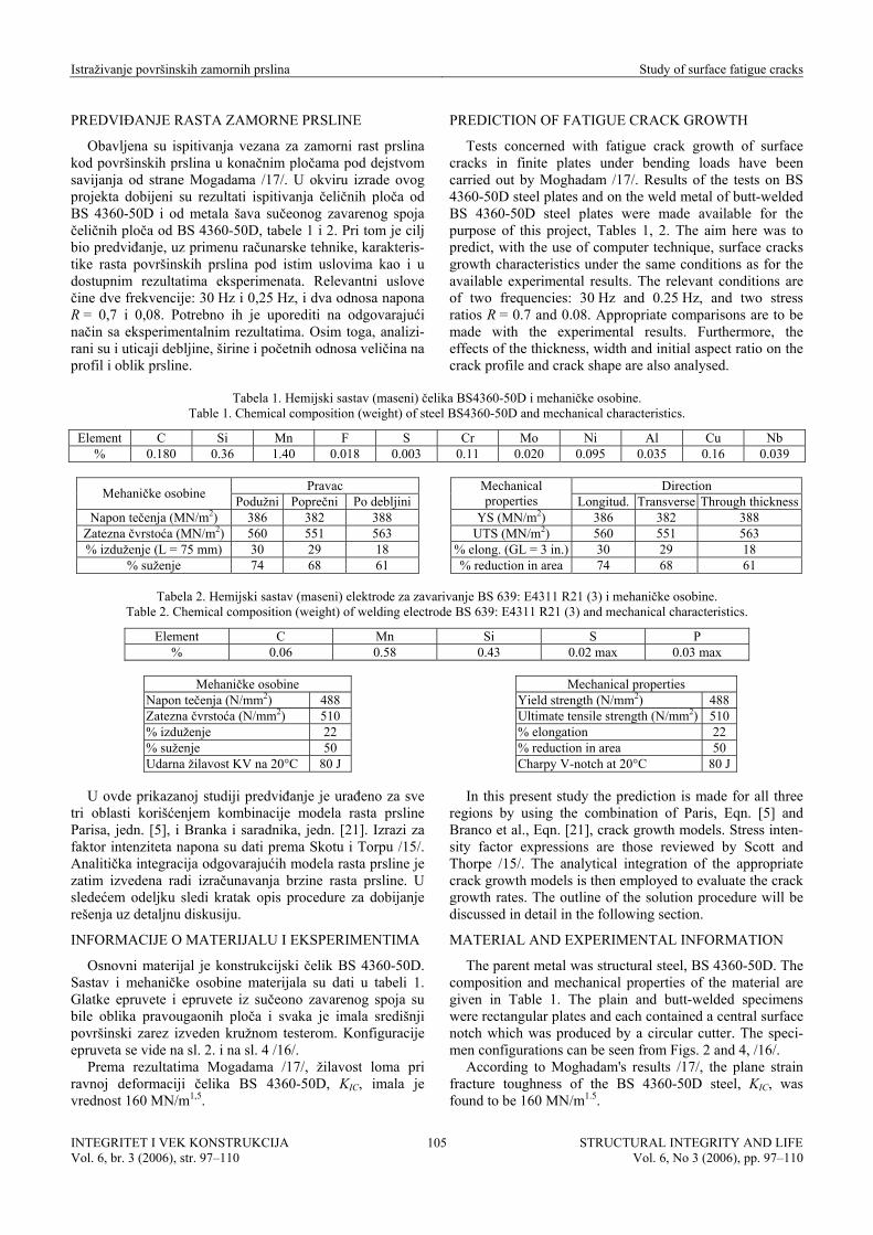
Obavljena su ispitivanja vezana za zamorni rast prslina kod površinskih prslina u konačnim pločama pod dejstvom savijanja od strane Mogadama /17/. U okviru izrade ovog projekta dobijeni su rezultati ispitivanja čeličnih ploča od BS 4360-50D i od metala šava sučeonog zavarenog spoja čeličnih ploča od BS 4360-50D, tabele 1 i 2. Pri tom je cilj bio predviđanje, uz primenu računarske tehnike, karakteris-tike rasta površinskih prslina pod istim uslovima kao i u dostupnim rezultatima eksperimenata. Relevantni uslove čine dve frekvencije: 30 Hz i 0,25 Hz, i dva odnosa napona R = 0,7 i 0,08. Potrebno ih je uporediti na odgovarajući način sa eksperimentalnim rezultatima. Osim toga, analizi-rani su i uticaji debljine, širine i početnih odnosa veličina na profil i oblik prsline.
PREDICTION OF FATIGUE CRACK GROWTH
Tests concerned with fatigue crack growth of surface cracks in finite plates under bending loads have been carried out by Moghadam /17/. Results of the tests on BS 4360-50D steel plates and on the weld metal of butt-welded BS 4360-50D steel plates were made available for the purpose of this project, Tables 1, 2. The aim here was to predict, with the use of computer technique, surface cracks growth characteristics under the same conditions as for the available experimental results. The relevant conditions are of two frequencies: 30 Hz and 0.25 Hz, and two stress ratios R = 0.7 and 0.08. Appropriate comparisons are to be made with the experimental results. Furthermore, the effects of the thickness, width and initial aspect ratio on the crack profile and crack shape are also analysed.
Tabela 1. Hemijski sastav (maseni) čelika BS4360-50D i mehaničke osobine. Table 1. Chemical composition (weight) of steel BS4360-50D and mechanical characteristics.
Element C Si Mn F S Cr Mo Ni Al Cu Nb % 0.180 0.36 1.40 0.018 0.003 0.11 0.020 0.095 0.035 0.16 0.039
Pravac Mehaničke osobine Podužni Poprečni Po debljini
Napon tečenja (MN/m2) 386 382 388 Zatezna čvrstoća (MN/m2) 560 551 563 % izduženje (L = 75 mm) 30 29 18
% suženje 74 68 61
Direction Mechanical
properties Longitud. Transverse Through thicknessYS (MN/m2) 386 382 388
UTS (MN/m2) 560 551 563 % elong. (GL = 3 in.) 30 29 18 % reduction in area 74 68 61
Tabela 2. Hemijski sastav (maseni) elektrode za zavarivanje BS 639: E4311 R21 (3) i mehaničke osobine.
Table 2. Chemical composition (weight) of welding electrode BS 639: E4311 R21 (3) and mechanical characteristics.
Element C Mn Si S P % 0.06 0.58 0.43 0.02 max 0.03 max
Mehaničke osobine
Napon tečenja (N/mm2) 488 Zatezna čvrstoća (N/mm2) 510 % izduženje 22 % suženje 50 Udarna žilavost KV na 20°C 80 J
Mechanical properties
Yield strength (N/mm2) 488 Ultimate tensile strength (N/mm2) 510 % elongation 22 % reduction in area 50 Charpy V-notch at 20°C 80 J
U ovde prikazanoj studiji predviđanje je urađeno za sve
tri oblasti korišćenjem kombinacije modela rasta prsline Parisa, jedn. [5], i Branka i saradnika, jedn. [21]. Izrazi za faktor intenziteta napona su dati prema Skotu i Torpu /15/. Analitička integracija odgovarajućih modela rasta prsline je zatim izvedena radi izračunavanja brzine rasta prsline. U sledećem odeljku sledi kratak opis procedure za dobijanje rešenja uz detaljnu diskusiju.
INFORMACIJE O MATERIJALU I EKSPERIMENTIMA
Osnovni materijal je konstrukcijski čelik BS 4360-50D. Sastav i mehaničke osobine materijala su dati u tabeli 1. Glatke epruvete i epruvete iz sučeono zavarenog spoja su bile oblika pravougaonih ploča i svaka je imala središnji površinski zarez izveden kružnom testerom. Konfiguracije epruveta se vide na sl. 2. i na sl. 4 /16/.
Prema rezultatima Mogadama /17/, žilavost loma pri ravnoj deformaciji čelika BS 4360-50D, KIC, imala je vrednost 160 MN/m1,5.
In this present study the prediction is made for all three regions by using the combination of Paris, Eqn. [5] and Branco et al., Eqn. [21], crack growth models. Stress inten-sity factor expressions are those reviewed by Scott and Thorpe /15/. The analytical integration of the appropriate crack growth models is then employed to evaluate the crack growth rates. The outline of the solution procedure will be discussed in detail in the following section.
MATERIAL AND EXPERIMENTAL INFORMATION
The parent metal was structural steel, BS 4360-50D. The composition and mechanical properties of the material are given in Table 1. The plain and butt-welded specimens were rectangular plates and each contained a central surface notch which was produced by a circular cutter. The speci-men configurations can be seen from Figs. 2 and 4, /16/.
According to Moghadam's results /17/, the plane strain fracture toughness of the BS 4360-50D steel, KIC, was found to be 160 MN/m1.5.
INTEGRITET I VEK KONSTRUKCIJA Vol. 6, br. 3 (2006), str. 97–110
STRUCTURAL INTEGRITY AND LIFEVol. 6, No 3 (2006), pp. 97–110
105

Istraživanje površinskih zamornih prslina Study of surface fatigue cracks
Slika 4. Shema detalja površinske prsline.
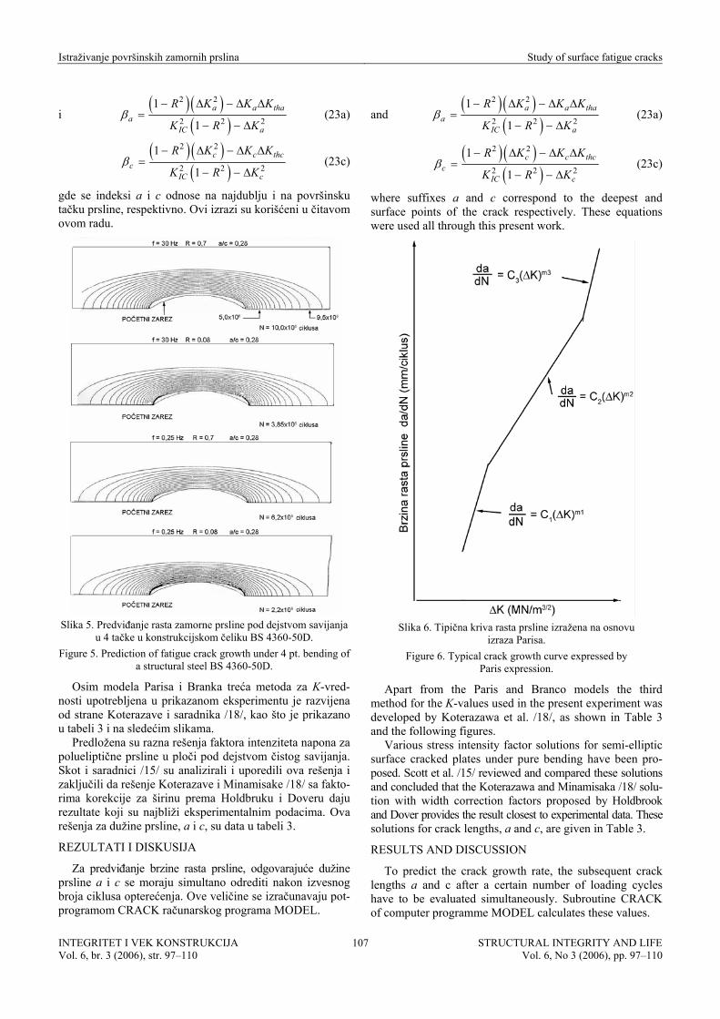
Kako je KIc jednako 160 MN/m1,5, a vrednost KIc metala šava nije bila poznata, pretpostavljena je ista vrednost kao i za osnovni metal. Vrednosti za Kth, međutim, su morale da se procene na osnovu eksperimentalnih krivih rasta prsline. Što se eksperimentalnih rezultata tiče, oni su se razlikovali u zavisnosti od uslova ispitivanja i materijala. Takođe je bilo teško proceniti ∆Kth za krive niže frekvencije (0,25 Hz) zbog poteškoća u dobijanju podataka za malu brzinu rasta prsline pri nižoj frekvenciji; prema tome, vrednosti ∆Kth na nižoj frekvenciji pretpostavljene su iste kao vrednosti na višoj frekvenciji (30 Hz), iako su postojali neznatni uticaji frekvencije pri vrednostima praga. Ovi uticaji su prikazani na sl. 5 /16/, i postaju više izraženi kod većih vrednosti faktora intenziteta napona, a takođe i pri većim odnosima napona.
Konfiguracija opterećenja je savijanje u 4 tačke sa konstantnom amplitudom ciklusa, što je prikazano na sl. 2.
MODELI RASTA ZAMORNE PRSLINE EPRUVETA SA POVRŠINSKOM PRSLINOM ZA SAVIJANJE (SCB)
Više modela rasta prsline je već predstavljeno u prethod-nom odeljku. Ovde će se detaljnije diskutovati o modelima jedn. [15] Parisa i jedn. [21] Branka i saradnika,. koji će se koristiti za predviđanje rasta zamorne prsline. Osnovna ideja je u predviđanju krivih rasta prsline za sve tri oblasti rasta prsline (sl. 3 i 6), prema tome, za tu svrhu izabrana je jedn. [21]. Pre primene jedn. [21] potrebno je poznavanje nekih osnovnih podataka kao što su brzine rasta prsline u oblasti II, a mogu se dobiti iz jedn. [15].
S obzirom na pretpostavku da su profili prslina polu-elipse, potrebno je izračunati samo brzine rasta za glavnu i pomoćnu osu. Stoga, jedn. [15] Parisovog modela može se napisati kao
( )ma a
da C KdN
= ∆ a (15a)
( )mc c
dc C K cdN
= ∆ (15c)
Slično se može napisati za model Branka i saradnika /13/
( ) aa a
da AdN
αβ= (22a)
( ) cc c
dc AdN
αβ= (22c)
Figure 4. Schematic showing details of the surface crack.
Since KIc was found to be 160 MN/m1.5, and KIc value of the weld metal was not known, it was assumed to have the same value as the parent metal. The values of Kth, however, had to be estimated from the experimental crack growth curves. As far as the experimental results are concerned, they were rather different depending on the test conditions and materials. It was also difficult to estimate the ∆Kth for the low frequency curves (0.25 Hz) due to difficulty in obtaining data at low crack growth rate at low frequency; therefore, ∆Kth values at low frequency were assumed to have the same values as those at the high frequency (30 Hz), although there were slight effects of frequency on the threshold values. These effects are shown in Fig. 5, /16/, and become greater at higher stress intensity factor range and also at higher stress ratio.
The loading configuration was 4-point bending with constant amplitude cycling, as shown in Fig. 2.
FATIGUE CRACK GROWTH MODELS FOR SURFACE CRACK BENDING (SCB) SPECIMENS
A number of crack growth models have already been presented in the previous section. Now, the Paris Eqn. [15] and Branco et al. Eqn. [21] models are discussed in more detail and are used for prediction of fatigue crack growth. The basic idea is to predict the crack growth curves for all three regions of crack propagation (Figs. 3 and 6), so Eqn. [21] is chosen for this purpose. Before applying Eqn. [21] some basic information, such as crack propagation rates in region II, are required and may be obtained from Eqn. [15].
Since the crack profiles are assumed to be semi-ellipses, only the growth rates of the major and minor axes need to be calculated. Thus, the Paris model Eqn. [15] may be written as
( )ma a
da C KdN
= ∆ a (15a)
( )mc c
dc C K cdN
= ∆ (15c)
Similarly, the Branco et al /13/ model may be written as
( ) aa a
da AdN
αβ= (22a)
( ) cc c
dc AdN
αβ= (22c)
INTEGRITET I VEK KONSTRUKCIJA Vol. 6, br. 3 (2006), str. 97–110
STRUCTURAL INTEGRITY AND LIFEVol. 6, No 3 (2006), pp. 97–110
106
Istraživanje površinskih zamornih prslina Study of surface fatigue cracks
i ( ) ( )
( )2 2
2 2 2
1
1a a t
aIC a
R K K K
K R Kβ
− ∆ − ∆ ∆=
− − ∆
ha (23a)
( ) ( )
( )2 2
2 2 2
1
1c c
cIC c
R K K K
K R Kβ
− ∆ − ∆ ∆=
− − ∆
thc (23c)
gde se indeksi a i c odnose na najdublju i na površinsku tačku prsline, respektivno. Ovi izrazi su korišćeni u čitavom ovom radu.
Slika 5. Predviđanje rasta zamorne prsline pod dejstvom savijanja
u 4 tačke u konstrukcijskom čeliku BS 4360-50D. Figure 5. Prediction of fatigue crack growth under 4 pt. bending of
a structural steel BS 4360-50D.
Osim modela Parisa i Branka treća metoda za K-vred-nosti upotrebljena u prikazanom eksperimentu je razvijena od strane Koterazave i saradnika /18/, kao što je prikazano u tabeli 3 i na sledećim slikama.
Predložena su razna rešenja faktora intenziteta napona za polueliptične prsline u ploči pod dejstvom čistog savijanja. Skot i saradnici /15/ su analizirali i uporedili ova rešenja i zaključili da rešenje Koterazave i Minamisake /18/ sa fakto-rima korekcije za širinu prema Holdbruku i Doveru daju rezultate koji su najbliži eksperimentalnim podacima. Ova rešenja za dužine prsline, a i c, su data u tabeli 3.
REZULTATI I DISKUSIJA
Za predviđanje brzine rasta prsline, odgovarajuće dužine prsline a i c se moraju simultano odrediti nakon izvesnog broja ciklusa opterećenja. Ove veličine se izračunavaju pot-programom CRACK računarskog programa MODEL.
and ( ) ( )
( )2 2
2 2 2
1
1a a t
aIC a
R K K K
K R Kβ
− ∆ − ∆ ∆=
− − ∆
ha (23a)
( ) ( )
( )2 2
2 2 2
1
1c c
cIC c
R K K K
K R Kβ
− ∆ − ∆ ∆=
− − ∆
thc (23c)
where suffixes a and c correspond to the deepest and surface points of the crack respectively. These equations were used all through this present work.
Slika 6. Tipična kriva rasta prsline izražena na osnovu
izraza Parisa. Figure 6. Typical crack growth curve expressed by
Paris expression.
Apart from the Paris and Branco models the third method for the K-values used in the present experiment was developed by Koterazawa et al. /18/, as shown in Table 3 and the following figures.
Various stress intensity factor solutions for semi-elliptic surface cracked plates under pure bending have been pro-posed. Scott et al. /15/ reviewed and compared these solutions and concluded that the Koterazawa and Minamisaka /18/ solu-tion with width correction factors proposed by Holdbrook and Dover provides the result closest to experimental data. These solutions for crack lengths, a and c, are given in Table 3.
RESULTS AND DISCUSSION
To predict the crack growth rate, the subsequent crack lengths a and c after a certain number of loading cycles have to be evaluated simultaneously. Subroutine CRACK of computer programme MODEL calculates these values.
INTEGRITET I VEK KONSTRUKCIJA Vol. 6, br. 3 (2006), str. 97–110
STRUCTURAL INTEGRITY AND LIFEVol. 6, No 3 (2006), pp. 97–110
107
Istraživanje površinskih zamornih prslina Study of surface fatigue cracks
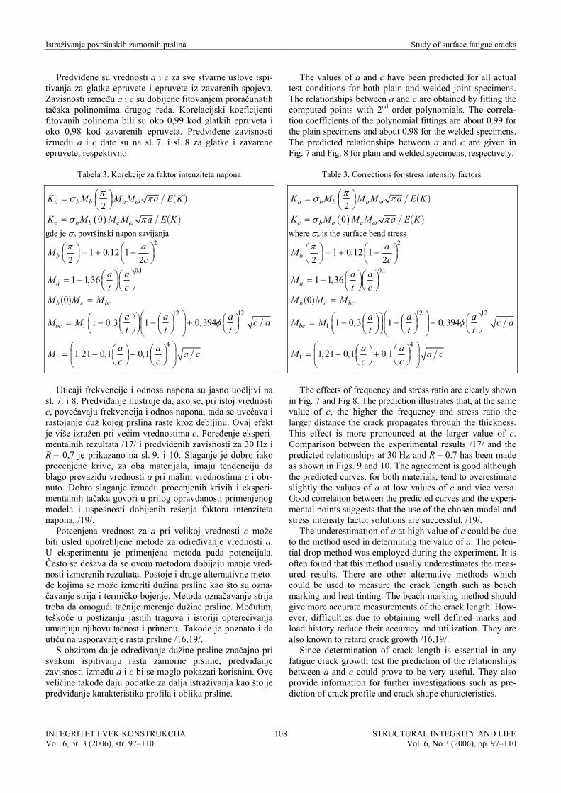
Predviđene su vrednosti a i c za sve stvarne uslove ispi-tivanja za glatke epruvete i epruvete iz zavarenih spojeva. Zavisnosti između a i c su dobijene fitovanjem proračunatih tačaka polinomima drugog reda. Korelacijski koeficijenti fitovanih polinoma bili su oko 0,99 kod glatkih epruveta i oko 0,98 kod zavarenih epruveta. Predviđene zavisnosti između a i c date su na sl. 7. i sl. 8 za glatke i zavarene epruvete, respektivno.
Tabela 3. Korekcije za faktor intenziteta napona
2a b b aK M M M a E/ ( )ω Kπσ π⎛ ⎞= ⎜ ⎟⎝ ⎠
( )0c b b cK M M M a E K/ ( )ωσ π=
gde je σb površinski napon savijanja 2
1 0 12 12 2b
aMc
,π ⎛ ⎞⎛ ⎞ = + −⎜ ⎟ ⎜ ⎟
⎝ ⎠ ⎝ ⎠
0 11 1 36a
a aMt c
,
, ⎛ ⎞ ⎛ ⎞= − ⎜ ⎟ ⎜ ⎟⎝ ⎠ ⎝ ⎠
0b c bcM M M( ) = 12 12
1 1 0 3 1 0 394bca a aM M c a/t t t
, , φ⎛ ⎞⎛ ⎞⎛ ⎞ ⎛ ⎞ ⎛ ⎞= − − +⎜ ⎟⎜ ⎟ ⎜ ⎟ ⎜ ⎟⎜ ⎟⎝ ⎠ ⎝ ⎠ ⎝ ⎠⎝ ⎠ ⎝ ⎠
4
1 1 21 0 1 0 1a aM a cc c
, , , /⎛ ⎞⎛ ⎞ ⎛ ⎞= − +⎜ ⎟⎜ ⎟ ⎜ ⎟
⎝ ⎠ ⎝ ⎠⎝ ⎠
Uticaji frekvencije i odnosa napona su jasno uočljivi na
sl. 7. i 8. Predviđanje ilustruje da, ako se, pri istoj vrednosti c, povećavaju frekvencija i odnos napona, tada se uvećava i rastojanje duž kojeg prslina raste kroz debljinu. Ovaj efekt je više izražen pri većim vrednostima c. Poređenje eksperi-mentalnih rezultata /17/ i predviđenih zavisnosti za 30 Hz i R = 0,7 je prikazano na sl. 9. i 10. Slaganje je dobro iako procenjene krive, za oba materijala, imaju tendenciju da blago prevaziđu vrednosti a pri malim vrednostima c i obr-nuto. Dobro slaganje između procenjenih krivih i eksperi-mentalnih tačaka govori u prilog opravdanosti primenjenog modela i uspešnosti dobijenih rešenja faktora intenziteta napona, /19/.
Potcenjena vrednost za a pri velikoj vrednosti c može biti usled upotrebljene metode za određivanje vrednosti a. U eksperimentu je primenjena metoda pada potencijala. Često se dešava da se ovom metodom dobijaju manje vred-nosti izmerenih rezultata. Postoje i druge alternativne meto-de kojima se može izmeriti dužina prsline kao što su ozna-čavanje strija i termičko bojenje. Metoda označavanje strija treba da omogući tačnije merenje dužine prsline. Međutim, teškoće u postizanju jasnih tragova i istoriji opterećivanja umanjuju njihovu tačnost i primenu. Takođe je poznato i da utiču na usporavanje rasta prsline /16,19/.
S obzirom da je određivanje dužine prsline značajno pri svakom ispitivanju rasta zamorne prsline, predviđanje zavisnosti između a i c bi se moglo pokazati korisnim. Ove veličine takođe daju podatke za dalja istraživanja kao što je predviđanje karakteristika profila i oblika prsline.
The values of a and c have been predicted for all actual test conditions for both plain and welded joint specimens. The relationships between a and c are obtained by fitting the computed points with 2nd order polynomials. The correla-tion coefficients of the polynomial fittings are about 0.99 for the plain specimens and about 0.98 for the welded specimens. The predicted relationships between a and c are given in Fig. 7 and Fig. 8 for plain and welded specimens, respectively.
Table 3. Corrections for stress intensity factors.
2a b b aK M M M a E/ ( )ω Kπσ π⎛ ⎞= ⎜ ⎟⎝ ⎠
( )0c b b cK M M M a E K/ ( )ωσ π=
where σb is the surface bend stress 2
1 0 12 12 2b
aMc
,π ⎛ ⎞⎛ ⎞ = + −⎜ ⎟ ⎜ ⎟
⎝ ⎠ ⎝ ⎠
0 11 1 36a
a aMt c
,
, ⎛ ⎞ ⎛ ⎞= − ⎜ ⎟ ⎜ ⎟⎝ ⎠ ⎝ ⎠
0b c bcM M M( ) = 12 12
1 1 0 3 1 0 394bca a aM M c at t t
, , /φ⎛ ⎞⎛ ⎞⎛ ⎞ ⎛ ⎞ ⎛ ⎞= − − +⎜ ⎟⎜ ⎟ ⎜ ⎟ ⎜ ⎟⎜ ⎟⎝ ⎠ ⎝ ⎠ ⎝ ⎠⎝ ⎠ ⎝ ⎠
4
1 1 21 0 1 0 1a aM a cc c
, , , /⎛ ⎞⎛ ⎞ ⎛ ⎞= − +⎜ ⎟⎜ ⎟ ⎜ ⎟
⎝ ⎠ ⎝ ⎠⎝ ⎠
The effects of frequency and stress ratio are clearly shown
in Fig. 7 and Fig 8. The prediction illustrates that, at the same value of c, the higher the frequency and stress ratio the larger distance the crack propagates through the thickness. This effect is more pronounced at the larger value of c. Comparison between the experimental results /17/ and the predicted relationships at 30 Hz and R = 0.7 has been made as shown in Figs. 9 and 10. The agreement is good although the predicted curves, for both materials, tend to overestimate slightly the values of a at low values of c and vice versa. Good correlation between the predicted curves and the experi-mental points suggests that the use of the chosen model and stress intensity factor solutions are successful, /19/.
The underestimation of a at high value of c could be due to the method used in determining the value of a. The poten-tial drop method was employed during the experiment. It is often found that this method usually underestimates the meas-ured results. There are other alternative methods which could be used to measure the crack length such as beach marking and heat tinting. The beach marking method should give more accurate measurements of the crack length. How-ever, difficulties due to obtaining well defined marks and load history reduce their accuracy and utilization. They are also known to retard crack growth /16,19/.
Since determination of crack length is essential in any fatigue crack growth test the prediction of the relationships between a and c could prove to be very useful. They also provide information for further investigations such as pre-diction of crack profile and crack shape characteristics.
INTEGRITET I VEK KONSTRUKCIJA Vol. 6, br. 3 (2006), str. 97–110
STRUCTURAL INTEGRITY AND LIFEVol. 6, No 3 (2006), pp. 97–110
108

Istraživanje površinskih zamornih prslina Study of surface fatigue cracks
Slika 7. Zavisnost između dužine prsline a i c za površinsku
prslinu u čeliku BS 4360-50D pod dejstvom savijanja u 4 tačke Figure 7. Predicted relationships between crack length a and c for
surface crack in BS 4360-50D steel under 4-point bending. Relacije između dužine prsline a i c (Relationships between crack length a and c)
2 27 6592 0 9211 0 92695 10a c. . ( ) . (−= − + − ⋅ c)
c)
c)
c)
c)
c)
c)
c)
.................. a 2 26 7936 0 8703 0 90192 10a c. . ( ) . (−= − + − ⋅ ................. b 2 26 9489 0 8725 0 89210 10a c. . ( ) . (−= − + − ⋅ .................. c 2 25 7872 0 7936 0 80736 10a c. . ( ) . (−= − + − ⋅ ................. d
Slika 8. Zavisnosti između dužine prsline a i c za površinsku prslinu u metalu šava sučeonog zavarenog spoja od čelika
BS 4360-50D pod dejstvom savijanja u 4 tačke Figure 8. Predicted relationships between crack length a and c for
surface crack in weld metal of butt-welded BS 4360-50D steel under 4-point bending.
Relacije između dužine prsline a i c (Relationships between crack length a and c)
2 25 7578 0 8887 0 95934 10a c. . ( ) . (−= − + − ⋅ .................. a 2 25 4801 0 2460 0 92873 10a c. . ( ) . (−= − + − ⋅ ................. b 2 25 9929 0 8763 0 99312 10a c. . ( ) . (−= − + − ⋅ .................. c 2 24 5888 0 7264 0 72257 10a c. . ( ) . (−= − + − ⋅ ................. d
Slika 9. Poređenje eksperimentalne i predviđene dužine prsline
a i c za površinsku prslinu u čeliku BS 4360-50D pod dejstvom savijanja u 4 tačke; 30 Hz, R = 0,7
Figure 9. Comparison between the experimental and predicted crack length a and c for surface crack in BS 4360-50D steel
under 4-point bending; 30 Hz, R = 0.7.
Slika 10. Poređenje eksperimentalne i predviđene dužine prsline a i c za površinsku prslinu u metalu šava sučeonog zavarenog spoja od čelika
BS 4360-50D pod dejstvom savijanja u 4 tačke; 30 Hz, R = 0,7 Figure 10. Comparison between the experimental and predicted
crack length a and c for surface crack in weld metal of butt-welded BS 4360-50D steel under 4-point bending; 30 Hz, R = 0.7.
INTEGRITET I VEK KONSTRUKCIJA Vol. 6, br. 3 (2006), str. 87–100
STRUCTURAL INTEGRITY AND LIFEVol. 6, No 3 (2006), pp. 87–100
109

Istraživanje površinskih zamornih prslina Study of surface fatigue cracks
ZAKLJUČCI
Predviđanje zamornog rasta prsline pri savijanju u 4 tač-ke čelika BS4360-50D sa površinskom prslinom i sučeonog zavarenog spoja izvedeno je korišćenjem rešenja za faktor intenziteta napona prema Skotu i Torpu /15/ i modela zamornog rasta prsline prema Branku i saradnicima /13/. Računarski programi koji sadrže metodu analitičke integra-cije su razvijeni i procene se zasnivaju na ovim programima i na pristupačnim eksperimentalnim rezultatima. Procena se može svesti na sledeće zaključke: (1) Zavisnosti za predviđanje odnosa veličine (dužine)
prsline po debljinu i duž pravca razvoja na površini daju manje vrednosti za a pri malim vrednostima c i obrnuto. Što su veći frekvencija i odnos napona to vrednosti a postaju sve veće za svaku zadatu vrednost za c za isti materijal.
(2) Krive predviđenog rasta prsline se dobro slažu sa eks-perimentalnim rezultatima i pokazuju da su brzine rasta prsline veće u pravcu na površini nego po debljini; veće su i pri većem odnosu napona; takođe su veće i u metalu šava nego u osnovnom metalu. Međutim, izves-ne krive predviđenog rasta prsline daju manje brzine rasta prsline u oblasti praga.
CONCLUSIONS
The prediction of fatigue crack growth under 4-point bending of a surface crack in BS4360-50D steel and butt-welded steel was carried out by using stress intensity factor solutions reviewed by Scott and Thorpe /15/ and a fatigue crack growth model proposed by Branco et al. /13/. Com-puter programmes employing analytical integration tech-nique have been developed and the prediction relies upon these programs and the available experimental results. The prediction may be summarised as follows (1) The predicted relationships between the crack length in
the through thickness and along the surface directions underestimate the values of a at low values of c and vice versa. The higher the frequency and stress ratio the larger the values of a become at any given values of c for the same material.
(2) The predicted crack growth curves correlate well with the experimental results and show that the crack growth rates are higher along the surface than through the thick-ness; higher at large stress ratio; and also higher in weld metal than in parent metal. However, some predicted crack growth curves underestimate the crack growth rates in the threshold region.
LITERATURA – REFERENCES
1. Irwin, G.R., Crack Extension Force for a Part-Through Crack in a Plate, J. Appl. Mech., Trans. ASME, 84, 1962, pp. 651-654.
2. Sneddon, I.N., The Distribution of Stress in the Neighbourhood of a Crack in an Elastic Solid, Proc. Roy. Soc. London A 187, 1946, pp. 229-260.
3. Green, A.E., Sneddon, I.N., The Distribution of Stress in the Neighbourhood of a Flat Elliptical Crack in an Elastic Solid, Proc. Cambridge Phil. Soc., 46, 1950, pp. 159-164.
4. Kobayashi, A.S., Moss, W.L., Stress Intensity Magnification Factor for Surface-Flawed Tension Plate and Notched Round Tension Bar, Proc. 2nd Int. Conf. Fract., Brighton England, 1969, pp. 31-45.
5. Shanley, F.R., A Theory of Fatigue Based on Unbonding During Reversed Slip, Rand Corp. Report No. P350 (Novem-ber, 1952), Also Supplement (1963).
6. Head, A.K., The Propagation of Fatigue Cracks, J. Appl. Mech. 23, 1956, pp.407.
7. Weibull, W., The Propagation of Fatigue Cracks in Light Alloy Plates, SAAB Aircraft CO., Linkoping, Sweden, 1954.
8. Paris, P.C., Erdogan, F., A Critical Analysis of Crack Propagation Laws, J. bas. Engng. Trans. ASME, Ser. D, 85, 4, 1963, pp. 528-534.
9. Hoeppner, D.W., Krupp, W.E., Prediction of Component Life by Application of Fatigue Crack Growth Knowledge, Eng. Fract. Mech. 6, 1974, pp. 47-70.
10. Erdogan, F., Fracture Advance Treatise, 1968, Academic Press, New York, pp. 497.
11. Frost, N.E., Pook, L.P., Denton, K.T., A Fracture Mechanics Analysis of Fatigue Crack Growth Data for Various Materials, Eng. Fract. Mech. 3, 1, 1971, pp. 109.
12. Foroughi, R., Radon, J.C., Random Loading Fatigue of the Welds in BS4360 steel, ICF, (Vol. 2), Houston, TX, USA, 1989, pp. 1141-8.
13. Branco, C.M., Radon, J.C., Culver, L.E., Influence of Mean Stress Intensity on Fatigue Crack Growth in an Aluminium Alloy, J. Mech. Eng. Sci. 17, 4, 1975, pp. 199-205.
14. Radon, J.C., A Model for Fatigue Crack Growth in a Threshold Region, Int. J. Fatigue, 1982, pp. 161-166.
15. Scott, P.M., Thorpe, T.W., A Critical Review of Crack Tip Stresses Intensity Factors for Semi-Elliptical Cracks, Fatigue of Eng. Mat. and Struc. 4, No4, 1981, pp. 291-309.
16. Musuva, J.K., Radon, J.C., An Elastic-Plastic Crack Growth Analysis using the J-integral Concepts, Proc. ECF 3, London, 1980, pp. 129-41.
17. Moghadam, S.P., Radon, J.C., The Effects of Mechanical and Environmental Variables on Fatigue Crack Propagation in Butt-welded Joints, Advances in Fracture Research, ICF 6, (Vol. 3), New Delhi, 1984, pp. 1999-2006.
18. Koterazawa, R., Minamisaka, S., Stress Intensity Factors of a Semi-elliptical Surface Cracks in Bending, J. Soc. Mater. Sci. Jap., 26, (1997) pp. 1-7.
19. Radon, J.C., Nikbin, K.H., Influence of Specimen Geometry, ASTM STP 1406, (2001) ISBN Ref. ID-2356.
INTEGRITET I VEK KONSTRUKCIJA Vol. 6, br. 3 (2006), str. 97–110
STRUCTURAL INTEGRITY AND LIFEVol. 6, No 3 (2006), pp. 97–110
110