study link classes
TRANSCRIPT

Digilnl Techniques Course Code: 22320
Program Name
Program Code
Semester
: Computer and Electronics Engineering Program Group
Course Title
Course Code
1. RATIONALE
: CO/CM/CW/DE/EJ/ET/EN/EX/EQ/IE/IS/IC/MU
: Third
: Digital Techniques
: 22320
In the present scenario most of the electronic equipment like computers, mobiles, music systems, A TM, automation and control circuits and systems are based on digital circuits which the diploma electronic engineering passouts (also called technologists) have to test them. The knowledge of basic logic gates, combinational and sequential logic circuits using discrete gates .as well as digital ICs will enable the students to interpret the working of equipment and maintain them. After completion of the course, students will be able to develop digital circuits based applications.
2. COMPETENCY The aim of this course is to help the student to attain the following industry identified competency through various teaching learning experiences:
• Buildl test digital logic circuits consist of digital ICs.
3. COURSE OUTCOMES (COs) The theory, practical experiences and relevant soft skills associated with this course are to be taught and implemented, so that the student demonstrates the following industry oriented COs associated with the above mentioned competency:
a. Use number system and codes for interpreting working of digital system. b. Use Boolean expressions to realize logic circuits. c. Build simple combinational circuits. d. Build simple sequential circuits. e. Test data converters and PLDs in digital electronics systems.
4. TEACHING AND EXAMINATION SCHEME Teaching
Examination Scheme Scheme
Credit Theory Practical (L+T+P) -
L T J> Paller ESE PA Total ESE PA Total
I-Irs. M,lX Min Max Min Max Min Max Min Max Min Max Min - f-- -4 - 2 6 3 70 28 30* 00 100 40 25# 10 25 10 50 20
(*): Under the Iheory PA, Out of 30 marks, J 0 marks are for micro-project assessment to focililale integration oleos and the remaining 20 morks is the average of 2 tests to he taken during the semester for the assessment of the cognitive domain UOs required for the al/ainment olthe COs. Legends: L-Lecture; T - Tutorial/Teacher Guided Theory Practice; P - Practical: C - Credit, ESE - End Semester Examination; PA - Progressive Assessment.
5. COURSE MAP (with sample COs, PrOs. UOs, ADOs and topics) This course map illustrates an overview of the flow and iTnkag.e· f the topics at variolls levels of outcomes (details in subsequent sections) to be attained by he ~SlUtlCn l by the end of the
) t
'\ f\ f~ MSBTE - Final Copy D1. 20.04.2018 Page 1 of9
,

Digilill Techniques
I
.,.- ------~ .-
.... '--------
.... , .................. _ ............... . ..... , ..... .
I ;. PrO IhlOugh Practi cal s ........ . ...... . ............................
;.-.~ . - ... -. -. I ' UO In Cogmllve ,
Domnin I ' ... - ' - . ~
Figure 1 - Course Map
6. SUGGESTED I>RACTICALSI EXERCISES
Course Code: 22320
,. -"-"--/' ,\ I)() .'[«live
............................. ... ..
lOlhC (JUlltnllll)tllu)ttlC"!
" ........... , ............... . '-- .. _ .. - '
The practicals in this section are PrOs (i.e. sub-components of the COs) to be developed and assessed in the student for the attainment of the competency .
S. No.
Practical Outcomes (PrOs)
1 Test the functionality of specified logic gates Llsing breadboard. (IC 7404, 7408. 7432. 7486)
2 Test the functionality of NAND and NOR gate of using breadboard (IC 7400 and 7402)
3 Construct AND, OR, NOT gates lIsing universal gates. 4 Build the logic circuit on breadboard to check the De Morgan's
theorems. 5 Design Half adder and Half subtractor using Boolean expressions. 6 Design Full adder and full subtractor. 7 Construct and test BCD to 7 segment decoder using [C)4471 744S . 8 Build 1 test function of MUX 7415 J 174150/any other e(i'lliv~lant. '
I~
MSBTE - Final Copy Dt. 20.04.2018
U ·
Unit No.
II
II
II II
111 III III
' m
.. I
Approx. Hrs.
required -02*
-02
02 02
02* --02 02 02
~
Page 201'9

Digital Techlliqucs Coursc Code: 22320
s. Unit Approx.
No. j>ractic::l1 Outcomes (PrOs)
No. Hrs.
required 9 Build / test function of DEMUX 74155174154/any other III 02
equivalant. 10 Build / test function ofRS flip flop using NAND Gate. IV 02* I 1 Build / test function ofMS JK flip flop using 7476. IV 02 12 Use IC 7476 to construct and test the functionality of D and T flip IV 02
flop. 13 Implement 4 bit ripple counter using 7476. IV 02 14 Use IC 7490 to construct decade counter (MOD-l 0) . IV 02 15 Implement 4 bit universal shift register. IV 02 16 Build R-2R resistive network on breadboard to convert given V 02*
digital data into analog. Total 32
Note i. A suggestive list of PrOs is given in the (lbove lahle. More such PrOs can he added to
a/fain the COs and competency. A judicial mix of minimum J 2 or more practical need to be pelj'urmed. out of which, the practicals marked as ,*, are compulsory, so that the student reaches the 'Precision Level' (~f Dave '.I' 'P.sychomotor Domain Taxonomy ' as generally required by the industJy.
ii. The 'Process' and 'Product' related skills associated wilh each PrO is 10 be assessed according to a suggested sample given below:
s. No. Performance Indicators Weightage in % a. Preparation of experimental set up 20 b. Setting and operation 20 c. Safety measures 10 d. Observations and Recording 10 e. Interpretation of result and conclusion 20 f. Answer to sample questions 10 g. Submission of report in time 10
Total 100
The above PrOs also comprise of the following social skills/attitudes which are Affective Domain Outcomes (ADOs) that are best developed through the laboratory/field based experIences:
a. Follow safety practices. b. Practice good housekeeping. c. Demonstrate working as a leader/a team member. d. Maintain tools and equipment. e. Follow ethical practices.
The ADOs arc not specific to anyone PrO, but are embedded in many PrOs. I-lence, the acquisition of the ADOs takes place gradually in the student when s/he undertakes a series of practical experiences over a period of time. Moreover, the level of achievement of the ADOs according to Krathwohl' s 'Affective Domain] .a.\,QlJO Illy' should gradually increase as planned below: . .
• 'Valuing Lever in 1 sf year
MSBTE - Final Copy Dt. 20.04.2018 Page 3 of 9
Course Code: 22320 Digit,lI Techniques --~----------------------------------------------------------
• '() ., I I" ",lid rgal1lSlI1gJcve . 111 L year
• 'CI .. L I" "rd laractenslIlg eve ' 111 J year.
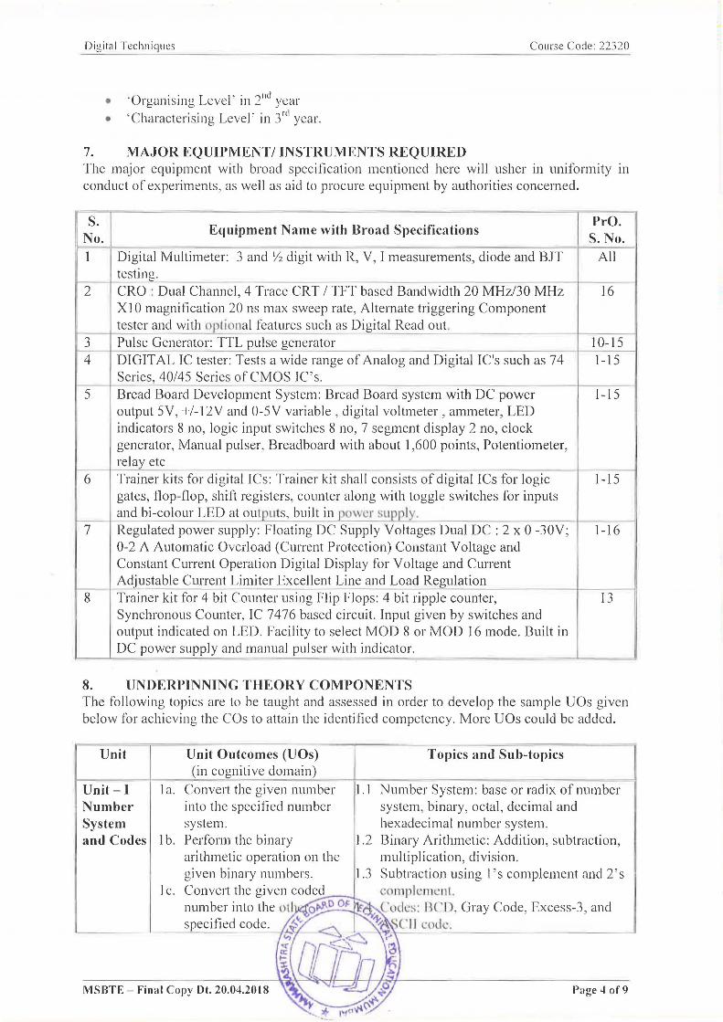
7. MAJOR EQUIPMENT/ INSTRUMENTS REQUIRED The major equipment with broad specification mentioned here will usher in uniformity in conduct of experiments, as well as aid to procure equipment by authorities concerned.
I.I --
Equipment Name with Broad Specifications PrO. S. No.
1 Dig ital Multimeter: 3 and Y2 digit with R, V, I measurements, diode and BlT All test mg.
2 CR o : Dual Channel, 4 Trace CRT / TFT based Bandwidth 20 MHz/30 MHz 16 Xl o magnification 20 ns max sweep rate, Alternate triggering Component test er and with oplional features such as Digital Read out.
3 Pul 4 DIG
se Generator: TTL pulse generator 10-15 IT AL IC tester: Tests a wide range of Analog and Digital IC's such as 74 1-15
Sel 'ies, 40/45 Series of CMOS IC's . 5 Bre ad Board Development System: Bread Board system with DC power 1-15
out put 5V, +1-l:z.V and 0-5V variable , digital voltmeter, ammeter, LED ind icators 8 no, logic input switches 8 no, 7 segment display 2 no, clock gen erator, Manual pulser, Breadboard with about 1,600 points, Potentiometer, rela y etc
6 Tra iner kits for digital ICs: Trainer kit shall consists of digital rcs for logic 1-15 gat es, flop-flop, shift registers, counter along with toggle switches for inputs and
~ Reg bi-colour LED at outputs , built in power supply , ulated power supply: Floating DC Supply Voltages Dual DC : 2 x 0 -30V; 1-16
0-2 A Automatic Overload (Current Protection) Constant Voltage ami Con stant Current Operation Digital Display for Voltage and Current Ad justable Current Limiter Excellent Line and Load Regulation -
8 Tra iner kit for 4 bit Counter using Flip Flops: 4 bit ripple counter, 13 SYI 1chronous Counter, IC 7476 based circuit. Input given by switches and out put indicated on LED. Facility to select MOD 8 or MOD 16 mode. Built in DC power supply and manual pulser with indicator.
8. UNDERPINNING THEORY COMPONENTS The following topics are to be taught and assessed in order to develop the sample UOs given below for achieving the COs to attain the identified competency. More UOs could be added.
Unit
Unit - I Number System
Unit Outcomes (UOs) (in cognitive domain)
Topics and Sub-topics
I a. Convert the given number 1.1 Number System: base or radix of number into the specified number system, binary, octal, decimal and system. hexadecimal number system.
and Codes lb. Perform the binary 1.2 Binary Arithmetic: Addition, subtraction, arithmetic operation on the multiplication, division. given binary numbers. 1.3 Subtraction using 1 's complement and 2's
I c. Convert the given coded cO lllpl CIll Cll l.
number into the u ti o~o OF _ Co II:::;: B( 'I) , Gray Code, Excess-3, and specified code. ~Ir., ~ '(' !l l:( dl:.
t;
MSBTE - Final Copy Dt. 20.04.2018
~ to~
Page 4 of9

Digital Techniques Course Code: 22320
Unit
Unit - II Logic gates and logic families
Unit- III Combinati onal Logic Circuits
Unit Outcomes (UOs) (in cognitive domain)
Topics and Sub-topics
1 d. Add the given two decimal 1.5 BCD Arithmetic: BCD Addition numbers using BCD code.
2a. Develop the basic gates 2.1 Logic gates: Symbol, diode/ transistor using the given NAND/NOR switch circuit and logical expression, gate as universal gate. truth table of basic logic gates (AND,
2b. Simplify the given OR, NOT), Universal gates (NAND and expression using Boolean NOR) and Special purpose gates (EX-laws. OR. EX-NOR).Tristate logic
2c. Develop logic circuits using 2.2 the given Boolean
Boolean algebra: Laws of Boolean algebra, Duality Theorem, De-Morgan's theorems
2d. expressions. Compare the salient characteristics of the given digital logic families.
3a. Develop logic circuits in standard SOP/ POS form for the given logical expression.
3b. Minimize the given logic expression using K-map.
3c. Use IC 7483 to design the given adder! subtractor.
3d. Draw MUX/DEMUX tree for the given number of input and output lines.
3e. Write the specifications of the component for the given application.
3f. Develop the specified type of code converter.
~. 3 Logic Families:Characteristics of logic families: Noise margin, Power dissipation, Figure of merit, Fan-in and fan-out, Speed of operation, Comparison of TTL, CMOS, types of TTL NAND gate
~-.1 Standard Boolean representation: Sum of Product (SOP) and Product of Sum( POS), Min-term and Max-term, conversion between SOP and POS forms, realization using NAND /NOR gates
3.2 K-map reduction technique for the Boolean expression: Minimization of Boolean functions up to 4 variables (SOP and POS form)
B.3 Design of arithmetic circuits and code converter using K-map: Half and full Adder, half and full Subtractor , gray to binary and binary to gray (up to 4 bits)
G.4 Arithmetic circuits: (IC 7483 ) Adder and Subtractor, BCD adder
B.5 Encoder/Decoder: Basics of encoder, decoder, comparison, (lC 7447) BCD to 7 segment decoder/driver
G.6 Multiplexer and Demultiplexer: working, truth table and applications of Multiplexers and Demultiplexures, MUX tree, IC 74151 as MUX; DEMUX tree, DEMUX as decoder, IC 74155 as DEMUX
G.7 Buffer: Tristate logic, unidirectional and bidirectional buffer
~~ (IC74LS244,74LS245)
~=---~~~~----~~/.~~¥?~·~~~~~~~~~~- F·~----~=-~~~~----'--/lJI c/) \~ ~ ~\~ )~
MSBTE - Final Copy 01. 20.04.2018 ~~ A.{Jl ~~It.)fi(jj ",\.~
Page50f9

Digitili Techniques Course Code: 22320
Unit Unit Outcomes (UOs) Topics and Sub-topics (in cognitive domain)
========---+======--Unit-IV Sequential Logic Circuit
Unit- V Data Converter
4a. Use relevant triggering technique for the given digital circuit.
4b. Use the given Jlip-flop to construct the specific type of counter.
4c. Use excitation table of the given flip-flop to design synchronous counter.
4d. Design the specified modulo-N counter using IC7490;
4e. Construct ring/ twisted ring counter using the given flip-flop.
Sa. Calculate the output voltage of the R-2R ladder for the
sand 5b. given specified digital input. Calculate the output voltage of the weighted resistor DAC for the given specified digital
PLDs
input. ~ c. Explain with sketches the
working principle of the given type of ADC.
Sd. Explain with sketches the working principle of the given types of memories .
Se. Explain with basic block diagram the working principle of the given type of
.1 Basic memory cell: RS-latch using NAND and NOR Triggering Methods: Edge trigger and level trigger SR Flip Flops: SR-flip flop, clocked SR flip flop with preset and clear, drawbacks of SR flip flop
.4 JK Flip Flops: Clocked JK Flip flop with preset and clear .. race around condition in JK flip flop, Master slave .JK flip flop, D and T type flip f10p Excitation table offlip f1ops, Block schematic and function table ofIC-7474, 7475
.5 Shift Register: Logic diagram of 4-bit Shift registers - Serial Input Serial Output, Serial Input Parallel Output, Parallel Input Serial Output, Parallel Input Parallel Output, 4 Bit Universal Shift register
' .6 Counters: Asynchronous counter: 4 bit Ripple counter, 4 bit up/down Counter, modulus of counter Synchronous counter: Design of 4 bit synchronous up/down counter Decade counter: Block schematic of Ie 7490 Decade counter, IC 7490 as MODN Counter, Ring counter, Twisted ring counter
5.1 Data Converter: DAC: Types, weighted resistor circuit and R-2R ladder circuit, DAC IC 0808 specifications
5.2
5.3
S.4
ADC: Block Diagram, types, and working of Dual slope ADC, SAR ADC, ADC IC 0808/0809, specification Memory: RAM and ROM basic building
blocks, read and write operation ,typcs of semiconductor memories PLD: Basic building blocks and types of PLDs, PLA, PAL, GAL CPLD: Basic Building blocks,
functionality.
mn .. '.rnmtnuble 10 Jic device. -*==~~ __ ===k==_
Note: To ollain the Co.\ and competency, above listed UOs need to he unde,.t({~ 'e the 'Application I,eve!' and above qj'Bloom's 'Cognitive Domain Taxonomy " hr:::P~ I~~
I.:. / ........ ~ <; ( .~ ~ ~ "', .... - , .....
" ~;\ ~ .. P, ' ~ r;pJ jt1-~ -'. - .- !,.~l ~~~~
MSBTE - Final Copy Dt. 20.04.2018

Digital Techniques Course Code: 22320
9. SUGGESTED SPECIFICATION TABLE FOR QUESTION PAPER DESIGN
Unit Unit Title Teaching Distribution of Theory Marks No. Hours R U A Total
Level Level Level Marks I Number System 06 2 2 4 08 II Logic gates and logic families 10 4 4 4 12 III Combinational Logic Circuits 16 4 6 8 18 IV Sequential Logic Circuit 16 4 6 8 18 V Data Converters and PLDs 16 4 4 6 14
Total 64 18 22 30 70 Legends: R=Remember, U=Understand, A=Apply and above (Bloom's Revised taxonomy) Note: This specification table provides general guidelines to assist student for their learning and to teachers to teach and assess students with respect to attainment of UOs. The actual distribution of marks at d[fJerent taxonomy levels (of R, U and A) in the question paper may vary from above table.
10. SUGGESTED STUDENT ACTIVITIES Other than the classroom and laboratory learning, following are the suggested student-related co-curricular activities which can be undertaken to accelerate the attainment of the various outcomes in this course: Students should conduct following activities in group and prepare reports of about 5 pages for each activity, also collect/record physical evidences for their (student's) portfolio which will be useful for their placement interviews:
a. Prepare the survey report on the applications of different types of number system and code converters used in the design of digital system.
b. Compare technical specifications and applications of various types of memory, PLDs, CPLDs and Prepare report.
c. Test digital IC's using various testing equipment like digital IC tester, Digital multi-meter etc.
d. Give seminar on any course relevant topic . e. Conduct library / internet survey regarding different data sheet and manuals. f. Prepare power point presentation on digital circuits and their applications. g. Undertake a market survey of different digital IC's required for different applications. h. Search for video / animations / power point presentation on internet for complex topic
related to the course and make a presentation.
11. SUGGESTED SPECIAL INSTRUCTIONAL STRATEGIES (if any) These are sample strategies, which the teacher can use to accelerate the attainment of the various learning outcomes in this course:
a. Massive open online courses (MOOes) may be used to teach various topics/sub topics.
b. 'L' in item No. 4 does not mean only the traditional lecture method, but different types of teaching methods and media that are to be employed to develop the outcomes.
c. About 15-20% of the topics/sub-topics which is relatively simpler or descriptive in nature is to be given to the students for self-directed learning and assess the development of the COs through classroom presentations (see implementation guideline for details).
d. With respect to item No.10, teachers opp0l1unities and provisions for co-curricular activities.
MSBTE - Final Copy ot. 20.04.2018 Page7of9

Digit<ll Techniques CUUI Sl: Cotk: 22320
c. (juidc student(s) in undertaking micro-projects. f. PPTs/Animations may be used to explain the construction and working of electronic
circuits. g. Guide students for using data sheets / manuals.
12. SUGGESTED MICRO-PROJECTS Only one micro-project is planned to be undertaken by a student that needs to be assigned to him/her in the beginning of the semester. In the first four semesters, the micro-project are group-based. However, in the fifth and sixth semesters, it should be preferably be individually undertaken to build LIp the skill and confidence in every student to become problem solver so that s/he contributes to the projects of the industry. In special situations where groups have to be formed for micro-projects, the number of students in the group should not exceed three. The micro-project could be industry application based, internet-based, workshop-based. laboratory-based or field -based. Each micro-project should encompass two or more COs which are in fact, an integration of PrOs, UOs and ADOs. Each student will have to maintain dated work diary consisting of individual contribution in the project work and give a seminar presentation of it before submission. The total duration of the micro-project should not be less than 16 (sixteen) student engagement hours during the course. The student ought to submit micro-project by the end of the semester to develop the industry oriented COs. Micro project report may be of four to five pages.
A suggestive list of micro-projects is given here. Similar micro-projects could be added by the concerned faculty:
a. Build a Digital IC tester circuit. b. Build a 4bit parity generator and parity checker circuit. c. Build a circuit to implement 4 bit adder. d. Build a circuit to test 7 segment display . c. Build a circuit to implement debounce switch. f. Build a circuit for LED flasher. g. Build a circuit for LED BAR display h. Design and analyze digital arithmetic circuit
Note: U::.:e general pwpose PCB/or making micro projects
13. SUGGESTED LEARNING RESOURCES
S. Title of Book j
Author Publication
No. ~
1 Modern Digital Jain, R.P . McGraw-Hill Publishing, New Electronics Delhi, 2009 ISBN: 97800706691] 6
2 Digital Circuits and Salivahanan S.; Vikas Publishing House, New Dellli, Design Arivazhagan S. 2013, ISBN: 978932596041] -,., Digital Electronics Puri, V.K. McGraw Hill, New Delhi, 2016, .J
ISBN: 97800746331751 4 Digital Principles Malvino, A.P.; McGraw Hill Education, New Delhi,
Leach, D.P. ; Saha G. 2014, ISBN: 9789339203405 -- -5 Digital Design Mano, Morris; Pearson Education India, Delhi.
Ciletti, Michael D . 2007, ISBN: 9780] 31989245 6 Digital Electronics, Maini , Anil K. Wiley India, Delhi, 2007,
Principles and ~OfTECHftl ISBN: 9780470032145
-. Integrated Circuits ~ ~ ~ /~7 ~~ \~\
~( fP ~ J 1;\ -r. 0 \~\ ll. l\ h /:..~I
MSBTE - Final Copy Dt. 20.04.2018 ~-# Po;"f"'''''-it ,~~ Page 8 of9

Digital Techniques Course Code: 22320
S. Title of Book
Author No. Publication
7 Digital Fundamentals
Floyd, Thomas Pearson Education India, Delhi, 2014, ISBN: 9780132737968
14. SUGGESTED SOFTW ARE/LEARNING WEBSITES a. www.cse.yorku.ca/~mack/1 OIl 101.NumberSystems.ppt b. www.people.sju.edu/~ggrevera/arch/slides/binary-arithmetic.ppt
c. www.mathsisfun.com/binary-number-system.html d. www.codesandtutorials.com/hardware/ electroni csl digital_ codes-types. php e. www.ee.surrey.ac.uk/Projects/Labview/gatesfunc/ f. www.ee.surrey.ac.uk/Projects/Labview/boolalgebra/ g. www.eng.auburn.edu/~strouce/class/elec2200Ielec2200-8.pdf
h. www.maxwell.ict.griffith.edu.au/yg/teaching/dns/dns_module3~3.pdf
1. www.scs.ryerson.ca/~aabhari/cps213Chapter5.ppt
J. www.eng.wayne.edu/~singhweb/seql.ppt
k. www.cs.sjsu.edu/faculty/leeICh2Problems2.ppt 1. www.rogtronics.net/files/datasheets/dac/SedraSmith.pdf m. www-old.me.gatech.edu/mechatronics_course/ADC_F04.ppt n. www.aIlaboutcircuits.com/vol_4/chpt_13/3.html o. www.youtube.com/watch?v=5Wz5f3n5sjs p. www.eee.metu.edu.tr/~cb/e447/Chapter%209%20-%20v2.0.pdf
q. www2.cs.siu.edu/~hexmoorlclasses/CS315-S09/Chapter9-ROM.ppt
r. www.cms.gcgll.org/attachments/article/95/Memory2.ppt s. www.cosc.brocku.ca/Offerings/3P92/seminars/Flash.ppt t. www.webopedia.com/TERMIRJRAM.html u. www.cs.sjsu.edu/~lee/cs 147 IRahman.ppt
MSBTE - Final Copy Dt. 20.04.2018 Page 9 of9