studio/ob/efp camera family bvp-e10 series camera family bvp-e10 series ... chapter 3 benefit of...
TRANSCRIPT

Studio/OB/EFP Camera Family BVP-E10 SeriesProduct Information Manual

Table of ContentsBVP-E10 Series Product Information Manual
2
Table of ContentsChapter 1 Introduction . . . . . . . . . . . . . . . . . . . . . . . . . . . . . . . . . . . . . . . . . . . . . . . . . . 91-1. Overview. . . . . . . . . . . . . . . . . . . . . . . . . . . . . . . . . . . . . . . . . . . . . . . . . . . . . . . . 101-2. Features and Benefits . . . . . . . . . . . . . . . . . . . . . . . . . . . . . . . . . . . . . . . . . . . . . . . 111-3. Creative Control . . . . . . . . . . . . . . . . . . . . . . . . . . . . . . . . . . . . . . . . . . . . . . . . . . . 121-4. Operational Versatility . . . . . . . . . . . . . . . . . . . . . . . . . . . . . . . . . . . . . . . . . . . . . . 15
Chapter 2 A Total System. . . . . . . . . . . . . . . . . . . . . . . . . . . . . . . . . . . . . . . . . . . . . . . 172-1. System Configuration . . . . . . . . . . . . . . . . . . . . . . . . . . . . . . . . . . . . . . . . . . . . . . . 182-2. Camera Head. . . . . . . . . . . . . . . . . . . . . . . . . . . . . . . . . . . . . . . . . . . . . . . . . . . . . 202-3. Viewfinders . . . . . . . . . . . . . . . . . . . . . . . . . . . . . . . . . . . . . . . . . . . . . . . . . . . . . . 212-4. Camera Control Unit . . . . . . . . . . . . . . . . . . . . . . . . . . . . . . . . . . . . . . . . . . . . . . . . 21
2-4-1 The CCU-700A/700AP has the following features: . . . . . . . . . . . . . . . . . . . 212-4-2 The CCU-550D/550DP has the following features:. . . . . . . . . . . . . . . . . . . 212-4-3 The CCU-900/900P has the following features. . . . . . . . . . . . . . . . . . . . . . 22
2-5. Control System . . . . . . . . . . . . . . . . . . . . . . . . . . . . . . . . . . . . . . . . . . . . . . . . . . . 232-5-1 Master Set-up Unit (MSU-700A and MSU-750) . . . . . . . . . . . . . . . . . . . . . 232-5-2 Camera Command Network Units (CNU-700 and CNU-500) . . . . . . . . . . 232-5-3 Video Selector (VCS-700) . . . . . . . . . . . . . . . . . . . . . . . . . . . . . . . . . . . . . . 232-5-4 Remote Control Panels (RCP-700 Series) . . . . . . . . . . . . . . . . . . . . . . . . . 23
2-6. System Setup Examples . . . . . . . . . . . . . . . . . . . . . . . . . . . . . . . . . . . . . . . . . . . . . 242-6-1 Connection Example Using CCU-550D/ 550DP. . . . . . . . . . . . . . . . . . . . . 242-6-2 Connection Example Using CCU-900/ 900P . . . . . . . . . . . . . . . . . . . . . . . 252-6-3 Connection Example Using CCU-700A/ 700AP . . . . . . . . . . . . . . . . . . . . . 27
2-7. Rack Mounting of System Equipment . . . . . . . . . . . . . . . . . . . . . . . . . . . . . . . . . . . . 29
Chapter 3 Benefit of Sony ADSP (Advanced Digital Signal Processing). . . . . . . . . 313-1. Full DSP Camera Processing . . . . . . . . . . . . . . . . . . . . . . . . . . . . . . . . . . . . . . . . . . 323-2. Maximum Dynamic Range. . . . . . . . . . . . . . . . . . . . . . . . . . . . . . . . . . . . . . . . . . . . 323-3. Other ADSP Functions. . . . . . . . . . . . . . . . . . . . . . . . . . . . . . . . . . . . . . . . . . . . . . . 333-4. Outstanding reliability and easy maintenance . . . . . . . . . . . . . . . . . . . . . . . . . . . . . . 393-5. Low power consumption . . . . . . . . . . . . . . . . . . . . . . . . . . . . . . . . . . . . . . . . . . . . . 39
Chapter 4 Control System . . . . . . . . . . . . . . . . . . . . . . . . . . . . . . . . . . . . . . . . . . . . . . 414-1. Sony Camera Control System. . . . . . . . . . . . . . . . . . . . . . . . . . . . . . . . . . . . . . . . . . 424-2. Master Set-up Unit - MSU-700A/750 . . . . . . . . . . . . . . . . . . . . . . . . . . . . . . . . . . . . . 424-3. Camera Command Network Units - CNU-500/ 700 . . . . . . . . . . . . . . . . . . . . . . . . . . . . 434-4. Remote Control Panels - RCP-700/ 701/ 750/ 751 . . . . . . . . . . . . . . . . . . . . . . . . . . . . 444-5. Flexible System Configuration. . . . . . . . . . . . . . . . . . . . . . . . . . . . . . . . . . . . . . . . . 464-6. File Structure. . . . . . . . . . . . . . . . . . . . . . . . . . . . . . . . . . . . . . . . . . . . . . . . . . . . . 474-7. Auto Set-up . . . . . . . . . . . . . . . . . . . . . . . . . . . . . . . . . . . . . . . . . . . . . . . . . . . . . . 474-8. Control Priority and Parallel Mode . . . . . . . . . . . . . . . . . . . . . . . . . . . . . . . . . . . . . . 484-9. S-BUS Control . . . . . . . . . . . . . . . . . . . . . . . . . . . . . . . . . . . . . . . . . . . . . . . . . . . . 48
Chapter 5 Optical Fibre Transmission System. . . . . . . . . . . . . . . . . . . . . . . . . . . . . . 515-1. Optical Fibre Overview . . . . . . . . . . . . . . . . . . . . . . . . . . . . . . . . . . . . . . . . . . . . . . 525-2. Cleaning of the Connector and Cable. . . . . . . . . . . . . . . . . . . . . . . . . . . . . . . . . . . . . 52
Chapter 6 A Quick Lesson on Camera Settings. . . . . . . . . . . . . . . . . . . . . . . . . . . . . 556-1. Camera Settings . . . . . . . . . . . . . . . . . . . . . . . . . . . . . . . . . . . . . . . . . . . . . . . . . . 56

3Table of ContentsBVP-E10 Series Product Information Manual
Chapter 7 Location and Function of Parts and Controls. . . . . . . . . . . . . . . . . . . . . . 577-1. BVP-E10 Series, Color Video Camera . . . . . . . . . . . . . . . . . . . . . . . . . . . . . . . . . . . . 58
7-1-1 Side Panels . . . . . . . . . . . . . . . . . . . . . . . . . . . . . . . . . . . . . . . . . . . . . . . . . 587-1-2 Front Panel . . . . . . . . . . . . . . . . . . . . . . . . . . . . . . . . . . . . . . . . . . . . . . . . . 60
7-2. CA-570/ 570P, Camera Adaptor . . . . . . . . . . . . . . . . . . . . . . . . . . . . . . . . . . . . . . . . 617-3. CA-950/ 950P, Camera Adaptor . . . . . . . . . . . . . . . . . . . . . . . . . . . . . . . . . . . . . . . . 647-4. CCU-550D/ 550DP, Camera Control Unit . . . . . . . . . . . . . . . . . . . . . . . . . . . . . . . . . . 67
7-4-1 Front Panel . . . . . . . . . . . . . . . . . . . . . . . . . . . . . . . . . . . . . . . . . . . . . . . . . 677-4-2 Rear Panel . . . . . . . . . . . . . . . . . . . . . . . . . . . . . . . . . . . . . . . . . . . . . . . . . 68
7-5. CCU-700A/ 700AP, Camera Control Unit . . . . . . . . . . . . . . . . . . . . . . . . . . . . . . . . . . 707-5-1 Front Panel . . . . . . . . . . . . . . . . . . . . . . . . . . . . . . . . . . . . . . . . . . . . . . . . . 707-5-2 Rear Panel . . . . . . . . . . . . . . . . . . . . . . . . . . . . . . . . . . . . . . . . . . . . . . . . . 71
7-6. CCU-900/ 900P, Camera Control Unit . . . . . . . . . . . . . . . . . . . . . . . . . . . . . . . . . . . . 737-6-1 Front Panel . . . . . . . . . . . . . . . . . . . . . . . . . . . . . . . . . . . . . . . . . . . . . . . . . 737-6-2 Rear Panel . . . . . . . . . . . . . . . . . . . . . . . . . . . . . . . . . . . . . . . . . . . . . . . . . 74
7-7. CNU-700, Camera Command Network Unit . . . . . . . . . . . . . . . . . . . . . . . . . . . . . . . . 767-7-1 Front and Rear Panels . . . . . . . . . . . . . . . . . . . . . . . . . . . . . . . . . . . . . . . . 76
7-8. CNU-500, Camera Command Network Unit . . . . . . . . . . . . . . . . . . . . . . . . . . . . . . . . 777-8-1 Front and Rear Panels . . . . . . . . . . . . . . . . . . . . . . . . . . . . . . . . . . . . . . . . 777-8-2 Internal Board . . . . . . . . . . . . . . . . . . . . . . . . . . . . . . . . . . . . . . . . . . . . . . . 78
7-9. VCS-700, Video Selector . . . . . . . . . . . . . . . . . . . . . . . . . . . . . . . . . . . . . . . . . . . . . 797-9-1 Front and Rear Panels . . . . . . . . . . . . . . . . . . . . . . . . . . . . . . . . . . . . . . . . 79
7-10. MSU-700A, Master Setup Unit . . . . . . . . . . . . . . . . . . . . . . . . . . . . . . . . . . . . . . . . 817-10-1 Operation Panel . . . . . . . . . . . . . . . . . . . . . . . . . . . . . . . . . . . . . . . . . . . . 817-10-2 Connector Panel . . . . . . . . . . . . . . . . . . . . . . . . . . . . . . . . . . . . . . . . . . . . 86
7-11. MSU-750, Master Setup Unit . . . . . . . . . . . . . . . . . . . . . . . . . . . . . . . . . . . . . . . . . 877-11-1 Operation Panel . . . . . . . . . . . . . . . . . . . . . . . . . . . . . . . . . . . . . . . . . . . . 87
7-12. RCP-700/701, Remote Control Panel. . . . . . . . . . . . . . . . . . . . . . . . . . . . . . . . . . . . 937-12-1 Operation Panel . . . . . . . . . . . . . . . . . . . . . . . . . . . . . . . . . . . . . . . . . . . . 93
7-13. RCP-750/751, Remote Control Panel. . . . . . . . . . . . . . . . . . . . . . . . . . . . . . . . . . . . 967-13-1 Operation Panel . . . . . . . . . . . . . . . . . . . . . . . . . . . . . . . . . . . . . . . . . . . . 967-13-2 Iris/master black control block (RCP-750) . . . . . . . . . . . . . . . . . . . . . . . . 997-13-3 Iris/master black control block (RCP-751) . . . . . . . . . . . . . . . . . . . . . . . 1007-13-4 Connector Panel . . . . . . . . . . . . . . . . . . . . . . . . . . . . . . . . . . . . . . . . . . . 101
7-14. RM-B150, Hand-held Remote Control Unite . . . . . . . . . . . . . . . . . . . . . . . . . . . . . . 1027-14-1 Operation Panel . . . . . . . . . . . . . . . . . . . . . . . . . . . . . . . . . . . . . . . . . . . 1027-14-2 Connector Panel . . . . . . . . . . . . . . . . . . . . . . . . . . . . . . . . . . . . . . . . . . . 106
7-15. RM-B750, Hand-held Remote Control Unite . . . . . . . . . . . . . . . . . . . . . . . . . . . . . . 1077-15-1 Operation Panel . . . . . . . . . . . . . . . . . . . . . . . . . . . . . . . . . . . . . . . . . . . 1077-15-2 Connector Panel . . . . . . . . . . . . . . . . . . . . . . . . . . . . . . . . . . . . . . . . . . . 109
7-16. BVF-77/77CE, Electronic Viewfinder . . . . . . . . . . . . . . . . . . . . . . . . . . . . . . . . . . . 1107-16-1 Appearance . . . . . . . . . . . . . . . . . . . . . . . . . . . . . . . . . . . . . . . . . . . . . . 1107-16-2 Adjusting the Angle of the Viewfinder. . . . . . . . . . . . . . . . . . . . . . . . . . . 111
7-17. BVF-55/ 55CE, Electronic Viewfinder . . . . . . . . . . . . . . . . . . . . . . . . . . . . . . . . . . . 1127-17-1 Appearances . . . . . . . . . . . . . . . . . . . . . . . . . . . . . . . . . . . . . . . . . . . . . 112
7-18. BVF-20W/20WCE, Electronic Viewfinder . . . . . . . . . . . . . . . . . . . . . . . . . . . . . . . . 1137-18-1 Appearances . . . . . . . . . . . . . . . . . . . . . . . . . . . . . . . . . . . . . . . . . . . . . 113
7-19. CA-905K/F/L, Large Lens Adaptor . . . . . . . . . . . . . . . . . . . . . . . . . . . . . . . . . . . . . 1147-19-1 Lens Attachment Section (Front) and Connectors . . . . . . . . . . . . . . . . . 1147-19-2 Camera-mounting Section (Inner Base) and the Optional BKP-9057

Table of ContentsBVP-E10 Series Product Information Manual
4
Viewfinder Saddle . . . . . . . . . . . . . . . . . . . . . . . . . . . . . . . . . . . . . . . . 1157-19-3 Rear control panel . . . . . . . . . . . . . . . . . . . . . . . . . . . . . . . . . . . . . . . . . 116
Chapter 8 Menu Settings . . . . . . . . . . . . . . . . . . . . . . . . . . . . . . . . . . . . . . . . . . . . . . 1198-1. MSU Security Settings . . . . . . . . . . . . . . . . . . . . . . . . . . . . . . . . . . . . . . . . . . . . . 120
8-1-1 Specifying the Security Code . . . . . . . . . . . . . . . . . . . . . . . . . . . . . . . . . . 1208-1-1-1 To set a new security code . . . . . . . . . . . . . . . . . . . . . . . . . . . . . 1208-1-1-2 To change the security code. . . . . . . . . . . . . . . . . . . . . . . . . . . . 1218-1-1-3 To override the security code . . . . . . . . . . . . . . . . . . . . . . . . . . . 121
8-1-2 Setting the Security Status . . . . . . . . . . . . . . . . . . . . . . . . . . . . . . . . . . . . 1228-1-3 MSU Assignment . . . . . . . . . . . . . . . . . . . . . . . . . . . . . . . . . . . . . . . . . . . 123
8-1-3-1 To restore operations of the MSU-700A/750 . . . . . . . . . . . . . . . . 1248-1-4 Setting the Operating Conditions of the MSU. . . . . . . . . . . . . . . . . . . . . . 125
8-1-4-1 To display the MSU Configuration menu. . . . . . . . . . . . . . . . . . . 1258-1-4-2 To set the built-in clock . . . . . . . . . . . . . . . . . . . . . . . . . . . . . . . . 1258-1-4-3 To adjust the buzzer sound. . . . . . . . . . . . . . . . . . . . . . . . . . . . . 1258-1-4-4 To turn on/off the buzzers independently . . . . . . . . . . . . . . . . . . 1268-1-4-5 To turn off all the buzzers . . . . . . . . . . . . . . . . . . . . . . . . . . . . . . 1268-1-4-6 To adjust the brightness of the LEDs . . . . . . . . . . . . . . . . . . . . . 1268-1-4-7 To adjust the brightness of the EL display . . . . . . . . . . . . . . . . . 1268-1-4-8 To adjust the brightness of the LED camera number displays
(MSU-750 only). . . . . . . . . . . . . . . . . . . . . . . . . . . . . . . . . . . 1268-1-4-9 To set the screen saver . . . . . . . . . . . . . . . . . . . . . . . . . . . . . . . . 127
8-2. Stand-alone Viewfinder Menu Tables for the BVP-E10 Series . . . . . . . . . . . . . . . . . . . 1288-2-1 Menu Items - Operation Menu . . . . . . . . . . . . . . . . . . . . . . . . . . . . . . . . . 1288-2-2 Menu Items - Paint Menu . . . . . . . . . . . . . . . . . . . . . . . . . . . . . . . . . . . . . 1298-2-3 Menu Items - Maintenance Menu . . . . . . . . . . . . . . . . . . . . . . . . . . . . . . . 1328-2-4 Menu Items - File Menu . . . . . . . . . . . . . . . . . . . . . . . . . . . . . . . . . . . . . . 1338-2-5 Menu Items - Diagnosis Menu . . . . . . . . . . . . . . . . . . . . . . . . . . . . . . . . . 133
Chapter 9 Connector Pin Assignment. . . . . . . . . . . . . . . . . . . . . . . . . . . . . . . . . . . . 1359-1. BVP-E10 Series, Color Video Camera . . . . . . . . . . . . . . . . . . . . . . . . . . . . . . . . . . . 136
9-1-1 Connector Input/Output Signals . . . . . . . . . . . . . . . . . . . . . . . . . . . . . . . . 1369-1-1-1 TEST OUT . . . . . . . . . . . . . . . . . . . . . . . . . . . . . . . . . . . . . . . . . . 1369-1-1-2 VF (20P FEMALE) . . . . . . . . . . . . . . . . . . . . . . . . . . . . . . . . . . . . 1369-1-1-3 ANALOG CA (68P FEMALE) . . . . . . . . . . . . . . . . . . . . . . . . . . . . 1379-1-1-4 DIGITAL CA (68P FEMALE) . . . . . . . . . . . . . . . . . . . . . . . . . . . . 138
9-2. CA-570/ 570P, Camera Adaptor . . . . . . . . . . . . . . . . . . . . . . . . . . . . . . . . . . . . . . . 1399-2-1 Connector Input/Output Signal . . . . . . . . . . . . . . . . . . . . . . . . . . . . . . . . . 139
9-2-1-1 PROMTER *1/GENLOCK *2 . . . . . . . . . . . . . . . . . . . . . . . . . . . . . 1399-2-1-2 TRIAX. . . . . . . . . . . . . . . . . . . . . . . . . . . . . . . . . . . . . . . . . . . . . . 1399-2-1-3 TEST OUT . . . . . . . . . . . . . . . . . . . . . . . . . . . . . . . . . . . . . . . . . . 1399-2-1-4 REMOTE (8P FEMALE) . . . . . . . . . . . . . . . . . . . . . . . . . . . . . . . . 1399-2-1-5 RET CONT (6P FEMALE). . . . . . . . . . . . . . . . . . . . . . . . . . . . . . . 1409-2-1-6 INCOM 1/2 (5P FEMALE) . . . . . . . . . . . . . . . . . . . . . . . . . . . . . . 1409-2-1-7 TRACKER (10P FEMALE) . . . . . . . . . . . . . . . . . . . . . . . . . . . . . . 1409-2-1-8 AUDIO IN 1/2 (3P MALE) . . . . . . . . . . . . . . . . . . . . . . . . . . . . . . 1409-2-1-9 DC IN (4P MALE). . . . . . . . . . . . . . . . . . . . . . . . . . . . . . . . . . . . . 1409-2-1-10 DC OUT (4P FEMALE). . . . . . . . . . . . . . . . . . . . . . . . . . . . . . . . 1419-2-1-11 VTR (26P MALE). . . . . . . . . . . . . . . . . . . . . . . . . . . . . . . . . . . . 1419-2-1-12 CAMERA (68P MALE) . . . . . . . . . . . . . . . . . . . . . . . . . . . . . . . . 142

5Table of ContentsBVP-E10 Series Product Information Manual
9-3. CA-950/ 950P, Camera Adaptor . . . . . . . . . . . . . . . . . . . . . . . . . . . . . . . . . . . . . . . 1439-3-1 onnector Input/Output Signals . . . . . . . . . . . . . . . . . . . . . . . . . . . . . . . . . 143
9-3-1-1 PROMTER *1/GENLOCK *2 . . . . . . . . . . . . . . . . . . . . . . . . . . . . . 1439-3-1-2 TEST OUT . . . . . . . . . . . . . . . . . . . . . . . . . . . . . . . . . . . . . . . . . . 1439-3-1-3 SERIAL IN/SERIAL OUT . . . . . . . . . . . . . . . . . . . . . . . . . . . . . . . 1439-3-1-4 REMOTE (8P FEMALE) . . . . . . . . . . . . . . . . . . . . . . . . . . . . . . . . 1439-3-1-5 RET CONT (6P FEMALE). . . . . . . . . . . . . . . . . . . . . . . . . . . . . . . 1439-3-1-6 INCOM 1/2 (5P FEMALE) . . . . . . . . . . . . . . . . . . . . . . . . . . . . . . 1449-3-1-7 AUDIO IN 1/2 (3P FEMALE) . . . . . . . . . . . . . . . . . . . . . . . . . . . . 1449-3-1-8 DC IN (4P MALE). . . . . . . . . . . . . . . . . . . . . . . . . . . . . . . . . . . . . 1449-3-1-9 DC OUT (4P FEMALE). . . . . . . . . . . . . . . . . . . . . . . . . . . . . . . . . 1449-3-1-10 CCU (MALE) . . . . . . . . . . . . . . . . . . . . . . . . . . . . . . . . . . . . . . . 1449-3-1-11 TRACKER (FEMALE) . . . . . . . . . . . . . . . . . . . . . . . . . . . . . . . . . 1449-3-1-12 CAMERA (68P MALE) . . . . . . . . . . . . . . . . . . . . . . . . . . . . . . . . 1459-3-1-13 CAMERA (68P MALE) . . . . . . . . . . . . . . . . . . . . . . . . . . . . . . . . 146
9-3-2 Wiring Diagrams for Cables . . . . . . . . . . . . . . . . . . . . . . . . . . . . . . . . . . . 1479-3-2-1 CCA-5 Cable . . . . . . . . . . . . . . . . . . . . . . . . . . . . . . . . . . . . . . . . 1479-3-2-2 REMOTE Cable (supplied with RM-B150). . . . . . . . . . . . . . . . . . 147
9-4. CCU-500D/ 500DP, Camera Control Unit . . . . . . . . . . . . . . . . . . . . . . . . . . . . . . . . . 1489-4-1 Connector Input/Output Signals . . . . . . . . . . . . . . . . . . . . . . . . . . . . . . . . 148
9-4-1-1 MIC OUTPUT CH1/CH2 (XLR 3P, MALE) . . . . . . . . . . . . . . . . . . 1489-4-1-2 WF MODE (4P FEMALE) . . . . . . . . . . . . . . . . . . . . . . . . . . . . . . . 1489-4-1-3 MIC REMOTE (D-Sub 15P, FEMALE) . . . . . . . . . . . . . . . . . . . . . 1489-4-1-4 INTERCOM/TALLY/PGM (D-Sub 25P, FEMALE). . . . . . . . . . . . . 1489-4-1-5 REMOTE (8P, FEMALE). . . . . . . . . . . . . . . . . . . . . . . . . . . . . . . . 1499-4-1-6 INTERCOM (5P, FEMALE) on the front panel . . . . . . . . . . . . . . . 149
9-5. CCU-700A/ 700AP, Camera Control Unit . . . . . . . . . . . . . . . . . . . . . . . . . . . . . . . . . 1499-5-1 Connector Input/Output Signals . . . . . . . . . . . . . . . . . . . . . . . . . . . . . . . . 149
9-5-1-1 MIC OUTPUT CH1/CH2 (3P, MALE) . . . . . . . . . . . . . . . . . . . . . . 1499-5-1-2 RTS IN/OUT . . . . . . . . . . . . . . . . . . . . . . . . . . . . . . . . . . . . . . . . . 1509-5-1-3 MIC REMOTE (15P, FEMALE) . . . . . . . . . . . . . . . . . . . . . . . . . . . 1509-5-1-4 INTERCOM REMOTE (25P, FEMALE) . . . . . . . . . . . . . . . . . . . . . 1509-5-1-5 INTERCOM/TALLY/PGM (19P, MALE) . . . . . . . . . . . . . . . . . . . . 1519-5-1-6 WF MODE (4P, FEMALE) . . . . . . . . . . . . . . . . . . . . . . . . . . . . . . 1519-5-1-7 REMOTE (8P, FEMALE). . . . . . . . . . . . . . . . . . . . . . . . . . . . . . . . 1519-5-1-8 INTERCOM (5P, FEMALE) on the front panel . . . . . . . . . . . . . . . 151
9-5-2 Cable Wiring Diagram . . . . . . . . . . . . . . . . . . . . . . . . . . . . . . . . . . . . . . . 1519-6. CCU-900/ 900P, Camera Control Unit . . . . . . . . . . . . . . . . . . . . . . . . . . . . . . . . . . . 152
9-6-1 Connector Input/Output Signals . . . . . . . . . . . . . . . . . . . . . . . . . . . . . . . . 1529-6-1-1 AUDIO OUTPUT CH-1/CH-2 (XLR 3-pin, Male) . . . . . . . . . . . . . 1529-6-1-2 WF MODE (4-pin Female) . . . . . . . . . . . . . . . . . . . . . . . . . . . . . . 1529-6-1-3 MIC REMOTE (D-sub 15-pin, Female) . . . . . . . . . . . . . . . . . . . . 1529-6-1-4 4 INTERCOM/TALLY/PGM (D-sub 25-pin, Female) . . . . . . . . . . 1529-6-1-5 WF MODE (D-sub 15-pin, Female) . . . . . . . . . . . . . . . . . . . . . . . 1539-6-1-6 AUX1 (D-sub 9-pin, Female) . . . . . . . . . . . . . . . . . . . . . . . . . . . . 1539-6-1-7 AUX2 (D-sub 9-pin, Female) . . . . . . . . . . . . . . . . . . . . . . . . . . . . 1539-6-1-8 TRUNK LINE1 (D-sub 9-pin, Female) . . . . . . . . . . . . . . . . . . . . . 1539-6-1-9 TRUNK LINE2 (D-sub 9-pin, Female) . . . . . . . . . . . . . . . . . . . . . 1549-6-1-10 INCOM REMOTE (D-sub 25-pin, Female). . . . . . . . . . . . . . . . . 1549-6-1-11 RCP/CNU (8-pin, Female) . . . . . . . . . . . . . . . . . . . . . . . . . . . . . 154

Table of ContentsBVP-E10 Series Product Information Manual
6
9-6-1-12 Front panel INTERCOM (5-pin, Female) . . . . . . . . . . . . . . . . . 1549-6-2 Cable Wiring Diagram . . . . . . . . . . . . . . . . . . . . . . . . . . . . . . . . . . . . . . . 155
9-7. CNU-700, Camera Command Network Unit . . . . . . . . . . . . . . . . . . . . . . . . . . . . . . . 1559-7-1 Connector Input/Output Signals . . . . . . . . . . . . . . . . . . . . . . . . . . . . . . . . 155
9-7-1-1 BNC connector 75 Ohms . . . . . . . . . . . . . . . . . . . . . . . . . . . . . . 1559-7-1-2 RS232C-1/2/3 *1 (9P, FEMALE) . . . . . . . . . . . . . . . . . . . . . . . . . . 1559-7-1-3 REMOTE (8P, FEMALE). . . . . . . . . . . . . . . . . . . . . . . . . . . . . . . . 155
9-7-2 Cable Wiring . . . . . . . . . . . . . . . . . . . . . . . . . . . . . . . . . . . . . . . . . . . . . . . 1559-7-3 Connection Connector . . . . . . . . . . . . . . . . . . . . . . . . . . . . . . . . . . . . . . . 155
9-8. CNU-500, Camera Command Network Unit . . . . . . . . . . . . . . . . . . . . . . . . . . . . . . . 1569-8-1 Connector Input/Output Signals . . . . . . . . . . . . . . . . . . . . . . . . . . . . . . . . 156
9-8-1-1 BNC connector 75 Ohms . . . . . . . . . . . . . . . . . . . . . . . . . . . . . . 1569-8-1-2 RS232C (9P, FEMALE) . . . . . . . . . . . . . . . . . . . . . . . . . . . . . . . . 1569-8-1-3 REMOTE (8P, FEMALE). . . . . . . . . . . . . . . . . . . . . . . . . . . . . . . . 156
9-8-2 Cable Wiring . . . . . . . . . . . . . . . . . . . . . . . . . . . . . . . . . . . . . . . . . . . . . . . 1569-8-3 Connection Connector . . . . . . . . . . . . . . . . . . . . . . . . . . . . . . . . . . . . . . . 156
9-9. VCS-700, Video Selector . . . . . . . . . . . . . . . . . . . . . . . . . . . . . . . . . . . . . . . . . . . . 1569-9-1 Connector Input/Output Signals . . . . . . . . . . . . . . . . . . . . . . . . . . . . . . . . 156
9-9-1-1 WF Mode (4P, female). . . . . . . . . . . . . . . . . . . . . . . . . . . . . . . . . 1579-9-1-2 Remote (8P, female) . . . . . . . . . . . . . . . . . . . . . . . . . . . . . . . . . . 1579-9-1-3 I/O Port (D-SUB 37P, female) . . . . . . . . . . . . . . . . . . . . . . . . . . . 157
9-10. MSU-700A, Master Setup Unit . . . . . . . . . . . . . . . . . . . . . . . . . . . . . . . . . . . . . . . 1589-10-1 Connector Input/Output Signals . . . . . . . . . . . . . . . . . . . . . . . . . . . . . . . 158
9-10-1-1 REMOTE (8-pin, Female). . . . . . . . . . . . . . . . . . . . . . . . . . . . . . 1589-10-1-2 I/O PORT (50-pin, Female) . . . . . . . . . . . . . . . . . . . . . . . . . . . . 158
9-10-2 Cable Wiring . . . . . . . . . . . . . . . . . . . . . . . . . . . . . . . . . . . . . . . . . . . . . . 1599-10-3 Connection Connector . . . . . . . . . . . . . . . . . . . . . . . . . . . . . . . . . . . . . . 159
9-11. MSU-750, Master Setup Unit . . . . . . . . . . . . . . . . . . . . . . . . . . . . . . . . . . . . . . . . 1599-11-1 Connector Panel . . . . . . . . . . . . . . . . . . . . . . . . . . . . . . . . . . . . . . . . . . . 159
9-12. RCP-750/751, Remote Control Panel. . . . . . . . . . . . . . . . . . . . . . . . . . . . . . . . . . . 1599-12-1 Connector Input/Output Signals . . . . . . . . . . . . . . . . . . . . . . . . . . . . . . . 159
9-12-1-1 AUX REMOTE . . . . . . . . . . . . . . . . . . . . . . . . . . . . . . . . . . . . . . 1599-12-1-2 EXT I/O . . . . . . . . . . . . . . . . . . . . . . . . . . . . . . . . . . . . . . . . . . . 160
9-12-2 Connection Connector . . . . . . . . . . . . . . . . . . . . . . . . . . . . . . . . . . . . . . 1609-13. CA-905K/F/L, Large Lens Adaptor . . . . . . . . . . . . . . . . . . . . . . . . . . . . . . . . . . . . . 160
9-13-1 Connector Input/Output Signals . . . . . . . . . . . . . . . . . . . . . . . . . . . . . . . 1609-13-1-1 REMOTE (8P, male) . . . . . . . . . . . . . . . . . . . . . . . . . . . . . . . . . 1609-13-1-2 LENS (12P, male) . . . . . . . . . . . . . . . . . . . . . . . . . . . . . . . . . . . 1609-13-1-3 LENS (36P, female) . . . . . . . . . . . . . . . . . . . . . . . . . . . . . . . . . . 1619-13-1-4 VF (20P, male) (BKP-9057) . . . . . . . . . . . . . . . . . . . . . . . . . . . . 1629-13-1-5 VF (25P, female) (BKP-9057) . . . . . . . . . . . . . . . . . . . . . . . . . . 162
Chapter 10 Glossary - Terms and Definitions . . . . . . . . . . . . . . . . . . . . . . . . . . . . . 16510-1. Hardware . . . . . . . . . . . . . . . . . . . . . . . . . . . . . . . . . . . . . . . . . . . . . . . . . . . . . 16610-2. Software. . . . . . . . . . . . . . . . . . . . . . . . . . . . . . . . . . . . . . . . . . . . . . . . . . . . . . 16910-3. Camera characteristics. . . . . . . . . . . . . . . . . . . . . . . . . . . . . . . . . . . . . . . . . . . . 170
Chapter 11 Specifications . . . . . . . . . . . . . . . . . . . . . . . . . . . . . . . . . . . . . . . . . . . . . 17111-1. BVP-E10, Color Video Camera . . . . . . . . . . . . . . . . . . . . . . . . . . . . . . . . . . . . . . . 17211-2. CA-570/ 570P, Camera Adaptor . . . . . . . . . . . . . . . . . . . . . . . . . . . . . . . . . . . . . . 17311-3. CA-950/ 950P, Camera Adaptor . . . . . . . . . . . . . . . . . . . . . . . . . . . . . . . . . . . . . . 174

7Table of ContentsBVP-E10 Series Product Information Manual
11-4. CCU-550D/ 550DP, Camera Control Unit . . . . . . . . . . . . . . . . . . . . . . . . . . . . . . . . 17411-5. CCU-700A/ 700AP, Camera Control Unit. . . . . . . . . . . . . . . . . . . . . . . . . . . . . . . . . 17711-6. CCU-900/ 900P, Camera Control Unit . . . . . . . . . . . . . . . . . . . . . . . . . . . . . . . . . . 17911-7. CNU-700, Camera Command Network Unit. . . . . . . . . . . . . . . . . . . . . . . . . . . . . . . 18011-8. CNU-500, Camera Command Network Unit. . . . . . . . . . . . . . . . . . . . . . . . . . . . . . . 18111-9. VCS-700, Video selector . . . . . . . . . . . . . . . . . . . . . . . . . . . . . . . . . . . . . . . . . . . 18111-10. MSU-700A, Master Setup Unit . . . . . . . . . . . . . . . . . . . . . . . . . . . . . . . . . . . . . . 18211-11. MSU-750, Master Setup Unit . . . . . . . . . . . . . . . . . . . . . . . . . . . . . . . . . . . . . . . 18311-12. RCP-700/701, Remote Control Panel . . . . . . . . . . . . . . . . . . . . . . . . . . . . . . . . . . 18411-13. RCP-750/751, Remote Control Panel . . . . . . . . . . . . . . . . . . . . . . . . . . . . . . . . . . 18511-14. RM-B150 (front panel), Hand-held Remote Control Unit . . . . . . . . . . . . . . . . . . . . . 18611-15. RM-B750 (front panel), Hand-held Remote Control Unit . . . . . . . . . . . . . . . . . . . . . 18611-16. BVF-10/10CE/20W/20WCE Viewfinder . . . . . . . . . . . . . . . . . . . . . . . . . . . . . . . . . 18711-17. BVF-55/ 55CE, 5-inch B/W Viewfinder . . . . . . . . . . . . . . . . . . . . . . . . . . . . . . . . . 18711-18. BVF-77/ 77CE, 7-inch B/W Viewfinder . . . . . . . . . . . . . . . . . . . . . . . . . . . . . . . . . 18811-19. CA-905F/905K, Large Lens Adaptor . . . . . . . . . . . . . . . . . . . . . . . . . . . . . . . . . . . 189
Appendix . . . . . . . . . . . . . . . . . . . . . . . . . . . . . . . . . . . . . . . . . . . . . . . . . . . . . . . . . . . 191


BVP-E10 Series Product Information Manual
11 Introduction
Chapter 6 A Quick Lesson on Camera Settings

1
Chapter 1 IntroductionBVP-E10 Series Product Information Manual
10
1-1. OverviewThe Sony BVP-900/950 camera family has gained a worldwide reputation as the flagship system for high-end Standard DefinitionTV (SDTV) programme origination in the studio and for outside broadcasts. As digital television agendas expand globally, Sony is responding to the increasingly diverse needs in programme creation.
The new BVP-E10 Series*1 of digital portable cameras is specifically intended to broaden its studio/OB system portfolio to meet those needs. New advances in CCD imager and DSP technologies have facilitated the development of a highly cost-effective and high-performance portable system that addresses the creative aspirations of the digital era.
At the heart of the outstanding picture performance delivered by the BVP-E10 Series is the newly developed Sony Power HADTM EX CCD sensor, specifically designed to support switchable progressive*2 and interlace scanning modes while also ensuring excellent sensitivity, noise and smear performance.
The use of new digital techniques has reduced the power consumption thus lowering the camera's internal operating temperature while increasing the stability of the signal processing circuitry, and improving operator comfort when the camera is shoulder mounted.
The BVP-E10*3 has been designed for 4:3 aspect ratio while the BVP-E10WS*3 is switchable between 4:3 and 16:9/ When combined with the Sony CA-570 Camera Adaptor and CCU-550A/700A Camera Control Unit, both models seamless integrate into current Sony camera systems from the very basic to the largest scale. These models can also be used with the Sony CA-950/950P Camera Adaptor and CCU-900/900P Camera Control Unit for fibre optic operations.
The BVP-E10 Series cameras are a highly sophisticated, yet cost effective solution for all acquisition requirements, and offer a wide choice of peripherals and accessories for operational flexibility
*1: Note: throughout this document,: "BVP-E10 Series" refers to the BVP-E10, BVP-E10WS, BVP-E10P, and BVP-E10WSP cameras:
"BVP-E10" refers to both the BVP-E10 (NTSC model) and BVP-E10P (PAL model) while BVP-E10WS refers to the BVP-E10WS (NTSC model) and BVP-E10WSP (PAL model)
*2: 25 PsF for E10P/E10WSP and 29.97 PsF for E10/E10WS
*3: “BVP-E10” refers to the both the BVP-E10 (NTSC model) and the BVP-E10P (PAL model); BVP-E10WS refers to both the BVP-E10WS (NTSC model) and the BVP-E10WSP (PAL model)

11Chapter 1 IntroductionBVP-E10 Series Product Information Manual
1-2. Features and BenefitsTwo Versions - the BVP-E10 and BVP-E10WSThe BVP-E10 Series consists of two versions - the BVPE10 and BVP-E10WS. The BVP-E10 is designed for high quality 4:3 acquisition, while the BVP-E10WS has the added capability of 16:9 and 4:3 switchable operations. Both cameras are engineered around the same core technology, which results in the high picture performance and sophisticated features that only the BVP-E10 Series can provide.
New Power HAD EX CCDThe newly developed Sony Power HAD EX CCD provides FIT standards of performance at the price level of IT cameras, with a remarkably low smear level of -140 dB (typical). an incredible pixel count of one million picture elements for NTSC and 1.2 million for PAL. At the same time, this CCD imager achieves a high sensitivity of f11, and an excellent S/N ratio of 65 dB (NTSC)/63 dB (PAL). These factors allow the BVP-E10 Series to make spectacular pictures even in the most difficult of shooting environments.
Photo 1-2-1: Newly Developed CCD and an Innovative LSI
12-bit A/D and Advanced Digital Signal Processing12-bit A/D resolution ensures that images created by the new Power HAD EX CCD are processed with great precision. This, in combination with the use of Advanced Digital Signal Processing (ADSP) and all-new LSI technology, provides comprehensive and precise control to make superb SDTV images.
3-D White ShadingThe BVP-E10 Series system replaces the traditional use of vertical and horizontal sawtooth and parabola waveforms for White Shading Correction. A digital 3-D multi-zone system, using numerous data points over the raster, creates a smooth correction topography that can far better handle the variations over many lens types and lens zooming ranges.
Cross Colour Suppression functionSeparating the luminance and chrominance components of a composite signal can be a difficult task, even with the most advanced comb filtering techniques. In order to keep cross colour and cross luminance to a minimum, the BVP-E10 Series virtually eliminates frequency components that may result in such artifacts being generated prior to the signal output. These frequency components are eliminated from the Y/R-Y/B-Y signals within the camera head by using sophisticated digital three line (NTSC)/five line (PAL)* comb filtering. This results in more greatly reduced cross colour and dot crawl than normally
seen on a picture monitor fed from a composite video signal.
* three line for PAL in PsF mode
Photo 1-2-2: Cross Colour Suppression On
On
Off

1
Chapter 1 IntroductionBVP-E10 Series Product Information Manual
12
1-3. Creative ControlLow Key SaturationWith conventional cameras, low light areas can be subject to a reduction in saturation. This can result in colour in these areas being "washed out". The Low Key Saturation function on the BVP-E10 Series eliminates this problem by optimizing the amplification of colour saturation at low light levels, providing more natural colour reproduction.
Photo 1-3-1: Low Key Saturation On
On
Off
Adaptive Highlight Control (Auto Knee Mode)In traditional cameras, only a single knee-point/slope is available for control over highlights. In the BVP-E10 Series cameras, multiple knee-points/slopes are provided for superior overexposure control. These cameras monitor the highlight areas of a scene and automatically set and optimize multiple knee points/slopes accordingly. This allows the reproduction of extremely difficult images (such as an interior scene which includes a brightly sunlit window) with much more overexposure latitude. This function applies only to input video levels in excess of the knee point, the middle and low luminance parts of the video signal are unaffected by this control.
Figure 1-3-1: Knee Curve Image
Knee Saturation ControlTraditionally, shooting very bright portions of an object (such as key light reflections off a forehead) can reduce colour saturation and change hue in highlight areas. The BVP-E10 Series adopts a new generation of the proven Knee Saturation Control function in which this 'wash out' effect on saturation and hue change is reduced to a minimum and far more natural colour reproduction in highlight areas is provided.
Photo 1-3-2: Knee Saturation On
On
Off
Multi-matrix FunctionUnlike conventional colour correction or matrix control, the Multi-matrix function allows colour adjustments to be applied over a colour range specified by the operator. The colour spectrum is divided into 16 areas
Inpu
t sig
nal l
evel
Output signal level
White clip
Knee point n
Knee point 0Knee point 1Knee point 2Knee point 3
Auto slope

13Chapter 1 IntroductionBVP-E10 Series Product Information Manual
of adjustment, where the hue and/or saturation of each area can be modified. This function is especially useful when only the hue of certain colours needs to be adjusted for special effects work.
Photo 1-3-3: Multi-matrix On
On
Off
Enhanced Vertical Detail (Non-Additive Mix)In conventional cameras, vertical detail signals are created using the Y-channel, G-channel or, more commonly, the R/G channels combined. Each method has its limitations, such as when the colour channel selected to create the detail signal is at a low level.
The BVP-E10 Series uses an adaptive image enhancement method. This creates detail signals from each of the R/G/B components of the video signal, compares them and then automatically selects the channel with the highest contrast level for use as the detail signal (Non-Additive Mix). This avoids the conventional restrictions of image enhancement observed above. Enhanced Vertical Detail is a process that automatically takes place within a BVP-E10 Series camera but, if required, operators may manually select from the Y, G, or R/G image enhancement modes.
Photo 1-3-4: Enhanced Vertical Detail (Non-Additive Mix) On
On
Off
Electronic Soft FocusThe Electronic Soft Focus included in these cameras applies an effect similar to using an optical soft-focus filter - but in a much more convenient way. Electronic Soft Focus uses the detail signal to reduce, rather than increase, the sharpness of the picture. By subtracting the detail signal from the original signal (as opposed to adding it as in conventional image enhancement), Electronic Soft Focus is able to provide a picture that is "softer" than that achieved when detail is switched off completely. Electronic Soft Focus is very effective when used in conjunction with Skin Tone Detail to only change the sharpness within a specific colour or hue range.
Adaptive Detail ControlThe Adaptive Detail Control automatically optimizes the amplitude of the detail signal for high-contrast picture edges and eliminating digital aliasing effects. The Adaptive Detail Control is able to achieve a very "natural" image enhancement during severe changes in contrast in a scene.

1
Chapter 1 IntroductionBVP-E10 Series Product Information Manual
14
Photo 1-3-5: Adaptive Detail Control On
On
Off
Triple Skin Tone Detail ControlSkin Tone Detail allows control of image enhancement within user-specified colour tones. The BVP-E10 Series allows enhancement to be set independently for up to three distinct colour and/or hue ranges.
The conventional use of Skin Tone Detail correction is to reduce the amount of detail control in areas of skin tone. With the BVP-E10 Series, correction is not restricted to areas of skin tones and can be set to apply to any colour areas. Image enhancement within the three areas can be increased or decreased relative to the overall image enhancement of a given scene.

15Chapter 1 IntroductionBVP-E10 Series Product Information Manual
1-4. Operational VersatilitySystem CompatibilityThe BVP-E10 Series is fully compatible with current Sony Camera Control Units. It seamlessly integrates with the Sony BVP-900 Series, BVP-700 Series and BVP-500 Series of camera systems and can be controlled using existing Sony MSUs, CNUs and RCPs. This allows systems from the very simplest to the most complex to be built around BVP-E10 Series cameras.
Photo 1-4-1: MSU-700A
Photo 1-4-2: CCU-550A with BKP-5973
Wide Band Triax Transmission SystemThe BVP-E10 Series is intended for optimal picture performance in outside broadcast applications as well as in the production studio. Major sporting and entertainment events regularly call for extended runs of the triax cable connecting the camera head unit to the remote CCU. In order to maintain the high picture performance of the BVP-E10 Series, the Sony wideband triax system has been incorporated. This triax system offers cable runs of up to 2,000 m (with return video and remote power) depending on the CCU and triax cable type.
Photo 1-4-3: Triax system
Fibre Optic Transmission SystemIn the event that even longer cable runs are required, the BVP-E10 Series is capable of fully digital transmission when used with a Sony CA-950 Fibre Optic Camera Adaptor and a CCU-900 Fibre Optic Camera Control Unit. The optical cables transmit the video signal in the digital domain, while extending the transmission distance up to 3,000 m* with power and return V/F, and up to 10,000 m* when utilizing local power. Adaptors are also available to provide interface between this system an standard telecoms fibre cables.
* The transmission distance may vary depending on the cable characteristics and number of connections made in the entire cable run


BVP-E10 Series Product Information Manual
12 A Total System

2
Chapter 2 A Total SystemBVP-E10 Series Product Information Manual
18
2-1. System ConfigurationThe Sony BVP-E10 Series is particularly designed to expand its studio and outside broadcast applications to meet the ongoing global demand for high cost-performance digital television acquisition with high-picture quality and operational flexibility. The following Figure 2-1-1 is a connection example for the applications in studio/OB van systems. As you can see in addition to the newly developed RCP-750/ 751Remote Control Panels, a variety of field-proven system components like the CNU-700/ 500 Camera Command Network Units, the MSU-700A / 750 Master Setup Units, CCU-900/ 900P / 700A/ 700AP/ 550D/ 550DP Camera Control Units, and the VCS-700 Video Selector help users to easily expand/upgrade their
systems. Both the wideband triax transmission system and fibre-optic transmission system are applicable in combination use with proper system component. On the lower left side of the figure, there is the CA-905, Large Lens Adaptor and 7-inch type viewfinder saddle, dedicated for the area where a larger studio or outside broadcast lens is needed. The Figure 2-1-2 shows its interface flexibility with various devices in a stand-alone system, where remote control can be provided by a standard RCP-700 series remote control panel, or the RM-B150 or RM-B750 hand held controllers. Figure 2-1-3 helps you understand all the optional accessories for the BVP-E10 Series.
Figure 2-1-1: Studio/OB van system
* Minor modification of camera head is required in combination use with the CA-553.
Figure 2-1-2: Stand-alone system
BVP-E10 Series Configured with Studio Lens
Fibre Optic CableTriax CableCommandCoaxial Cable
BVF-10/10CEBVF-20W/20WCE
+CA-950/950PCCU-900/900P
Studio Lens BVP-E10/E10P+CA*+CA-905** BVF-55 or BVF-77 with BKP-9057
CCU-700A/700AP
BVF-55/55CE
BVF-55/55CE
CCU-550D/550DPwith BKP-5973
MSU-700A/750
VCS-700
CNU-700/500
RCP-750/751
BVP-E10/E10PBVP-E10WS/E10WSP
+CA-570/570PBVP-E10/E10PBVP-E10WS/E10WSP
+CA-570/570PBVP-E10/E10PBVP-E10WS/E10WSP
** CA-905L - Fibre CA-905K/F - Triax* Ether the CA-570 or CA-950 cam be used in this configuration
BVF-10/10CEBVF-20W/20WCE
RM-B150/750RCP-700/701/750/751
CA-570/570P
BVV-5/5P
DNV-5
CA-553*
DVW-250/250P
BVW-50/50P
SDI
CCZ
CommandAC-550/550CE
BVP-E10/E10PBVP-E10WS/E10WSP

19Chapter 2 A Total SystemBVP-E10 Series Product Information Manual
Figure 2-1-3: Optional accessories for BVP-E10
RM-B750
MONITOR
FUNCTIONVF DISP
MENU SELECT
MAINTENANCEVF MENU
SCENECANCEL
PAINTENTER
ALARM
PANELACTIVE
MEMORYSTICK
STANDARD TEST BARS CLOSE
AWB
AUTOIRIS
IRIS/MBACTIVE MASTER
BLACK
REMOTE CONTROL UNIT RM-B750
EXT
IRIS
WHITE
BLACK
ABB
VTRSTART/STOP
COLOR VIDEO CAMERABVP-E10 Series
ZOOM LENS
Memory Stick
REMOTE CABLE(max. 100 m)
REMOTECONTROLUNIT( )RM-B150
CCZ CABLE
CCZ CABLE
VTR
RECORDER UNITDNV-5
CAMERA ADAPTORCA-3A
BETACAMADAPTORCA-553
VIDEO CASSETTERECORDERBVV-5/5PS
REMOTECONTROLPANEL
RCP-700RCP-701RCP-720RCP-721RCP-750RCP-751
AC ADAPTORAC-550/550CE
CCA-5 CABLE(max. 50m)
DIGITAL VIDEO CASSETTERECORDERDVW-250/250P
CAMERA ADAPTORCA-570/570PCA-950/950PCA-530
ELECTRONICVIEWFINDERBVF-55/55CE
2-inch VF(BVF-20W/20WCE)1.5-inch VF(BVF-10/10CE)
MASTERSETUPUNIT
MSU-700AMSU-750
RETURN VIDEOSELECTORCAC-6
Microphone
CAC-12Microphone Holder
Carryng case
Water-proof case
VCT-14Tripod Adaptor
Tripod

2
Chapter 2 A Total SystemBVP-E10 Series Product Information Manual
20
2-2. Camera HeadThe BVP-E10 is an outstanding colour video camera that incorporates Sony ADSP (Advanced Digital Signal Processing) and 12-bit A/D conversion. Using the new Power HAD EX CCD with its excellent highlight handling, the BVP-E10 provides a 900 TV line resolution (4:3), or 700TVL (16:9) and achieves the remarkably low smear level of• 140dB. Just some of the state-of-the-art features are:• Triple skin tone detail• Adaptive detail control• Fine detail• Electronic soft focus• Adaptive highlight control• Knee saturation• Low key saturation control• 3-D white shading• Multi matrix control• Skin tone auto iris
These improvements contribute to an unsurpassed image quality, making the BVP-E10 ideal for a wide range of applications from field acquisition to studio/OB camera system. The BVP-E10 can be controlled either at the camera head or by remote control through studio system peripherals such as the CCU-900/ 900P/ 700A/ 700AP/ 550A/ 550AP Camera Control Unit, MSU-700A/ 750 Master Set-up Unit and CNU-700/CNU-500 Camera Command Network Units.
The flexible interfacing of the BVP-E10 means that it is not only a high-end broadcasting camera with the latest technology, but it can also be easily integrated into the familiar studio/ OB vehicle systems that use earlier models of Sony cameras.
Main Features of Camera Heads
Excellent Picture Quality
BVP-E10 Resolution 900 TVL, Modulation depth 80% at 5 MHzBVP-E10WSResolution 700 TVL , (16:9 and 4:3 modes)Modulation depth 80% (16:9 mode), 60% (4:3 mode)• Total absence of lag and highlight artifacts
Wide band triax transmission• 10 MHz for luminance channel• 6MHz chrominance channel• Up to 2,000 m cable length with return video and
remote power (when using o14.5 mm cable and CCU-700A/700AP)
• Up to 1,000 m cable length with return video and remote power (when using o8.5 mm cable andCCU-700A/700AP)
• please add 11 mm triax specification, since this is the most common
Fibre optic transmissionUp to 3,000 m cable length with return video and remote power (when used with CA-950 Fibre Optic Camera Adaptor and CCU-900 Fibre Optic Camera Control Unit)
Enhanced Camera Operator functionsUp to four (with CA-570/570P) selectable return video feeds
Advanced intercom system• Individual ENG/PROD lines (except with CCU-550D/
DP)• Dual Programme Microphone system• Proagramme audio system
Compact size and easy maintenance• Highly sophisticated mechanical design• Approx. 2.5 kg (5 lb 8 oz) (not including viewfinder)• All boards plug-in for easy maintenance
Convenient return video selectUp to four return video signals can be selected for operational convenience. Return video switches and intercom switch are fitted on the carrying handle of the BVP-E10 to suit various shooting styles.
Comfortable operationThe shoulder pad of the BVP-E10 with a new soft material comfortably molds to the operator's shoulder. It also incorporates a pivoting chest pad and does not require forward/ backward adjustment.
- Sensitivity: F11 at 2000 lx - S/N (Typical): 65 dB (NTSC), 63 dB (PAL)- Smear level: -140 dB

21Chapter 2 A Total SystemBVP-E10 Series Product Information Manual
2-3. ViewfindersFor hand held or on-the-shoulder applications, there are two types of monocular black and white CRT viewfinders. The BVF-20W (NTSC)/ 20WCE (PAL) is a true wide screen 2-inch (16:9 aspect ratio) viewfinder, while the BVF-10 (NTSC)/ 10CE (PAL) is a 1.5-inch 4:3 standard viewfinder. Both provide high resolution of 600 TV lines at centre. For studio and OB applications, the BVF-55/ 55CE, a 5-inch monochrome viewfinder, is
available. If the camera is used with the CA-905K/F/L large lens adaptor and BKP-5097 viewfinder cradle, a larger 7" viewfinder can be used. The BVF-77/77CE is a high performance 7-inch monochrome viewfinder with extremely high horizontal resolution. All of these models are very compact in size, light in weight and economical in power consumption.
2-4. Camera Control UnitThe CCU-700A/700AP is a camera control unit for use with BVP-E10 Series cameras. By incorporating wideband Triax transmission , three optional SDI outputs, and a digital control system, as well as, the CCU-700A/700AP offers maximum camera performance combined with flexible operation. It has been designed to achieve the highest reliability, afford easy maintenance and allow flexible system configuration.
The compact Camera Control Unit, CCU-550D/550DP, is also available for use with BVP-E10 Series. A compact body, two SDI outputs and optional 12 V DC operation (BKP-5974) make this unit ideal for field use.
The CCU-900/900P Fibre Optic Camera Control Unit is for applications where even longer cable runs are required. Used together with the CA-950/950P fibre adaptor, the CCU-900/900P provides full digital transmission using hybrid copper/fibre cables. Transmission distances of up to 3,000 metres are possible without degradation, including camera power and return viewfinder signals. Even longer distance transmission up to 10,000 metres is possible if power is supplied locally to the camera.
2-4-1 The CCU-700A/700AP has the following features:
Wideband triax transmission• 10 MHz luminance channel for high performance
transmission; 6 MHz for each colour difference signals
• Up to 2000 m cable length (with φ14.5 mm cable)• Up to 1200 m cable length (with φ11.0 mm cable)• Up to 1,000 m cable length (with φ8.5 mm cable)• Return video (up to 2000 m with φ14.5 mm cable,
1200 m with φ11.0 mm cable, and 1,000 m with φ8.5 mm cable)
• Prompter video (up to 1000 m with φ14.5 mm cable, 625 m with φ11.0 mm cable, and 500 m with φ8.5 mm cable)
Easy-to-operate command system• Immediate response• Wide range of remote controls
Mono colour functionMono colour video is available to VBS and Y, R-Y and B-Y outputsAll colour information in the picture is replaced by a single colour, for which the hue (360 degrees) and saturation can be controllable from an MSU-700A/750A/750 Master Set-up Unit
Character display• Self diagnostics and other information may be
displayed on a monitor or superimposed on the picture monitoring output
• Characters, such as the camera number, can be superimposed on the internal colour bar signal
Component SDI output (option)Three component SDI outputs are optionally available for interfacing to the ever increasing range of component digital equipment and facilities
Built-in contrast and saturation functionsContrast, saturation and chroma on/off controls provided
Flexible intercom systemIndividual channels for production and engineering talkback4W, 2W or RTS selectable by internal switch
Remotely controllable MIC input gain (camera head)The gain of the two camera head programme microphone inputs is remotely controllable from the CCU in 10 dB steps (-60 dB ~ -20 dB). Control is also available via a connector on the rear of the CCU
Flicker-less sequential mode (RGB) standard for WFM outputRGB sequential monitoring without flicker
Compact size and easy maintenance• 19-inch wide and 3U high, including camera power
supply unit• Plug-in boards and plug-in power supply unit for
easy maintenance
2-4-2 The CCU-550D/550DP has the following features:
Wide variety of system configurationsTwo SDI signal outputs (digital component video each with two channels of embedded audio) may be used. When equipped with the optional BKP-5973 CCU Control Panel, the BKP-5973 can be used to control the video camera directly, without the use of a RCP-700 Series Remote Control Panel or the RM-B150 Remote Control Unit.
Note:The BKP-5973 does not work when the CCU-550D/550DP is connected to the CNU-700/500 Camera Network Unit. When the optional BKP-5974 DC Power Unit is attached, a DC power source may be used. The CCU-550D/550DP supports communications between the video camera and the CCU-550D/550DP over

2
Chapter 2 A Total SystemBVP-E10 Series Product Information Manual
22
either a triax cable or coaxial cable. (Power, however, is not supplied to the video camera in the case of coaxial cable.)
10-MHz, wideband triax transmissionPrompter signal transmission. Wideband triax transmission with Y signal at 10 MHz, R-Y and B-Y signals at 6 MHz is used for inputting video signals from the video camera. Maximum length of triax cable is 700 meters (with diameter of 8.5 mm), 875 meters (with diameter of 11.0 mm), 1,050 meters (BELDEN 9232 with diameter of 13.2 mm), or 1,400 meters (with diameter of 14.5 mm).
Rack mountableTwo CCU-550D/550DPs can be mounted side by side in a standard 19- inch EIA rack when using an optional RMM-301 Rack Mount Adaptor.
2-4-3 The CCU-900/900P has the following features.
Multiple video inputs and outputsThe CCU-900/900P has three SDI (Serial Digital Interface) signal outputs, an SDI picture monitor output, and four component SDI signal inputs. The CCU-900/900P also has two analogue waveform monitor outputs, two picture monitor outputs, and four return video inputs. It also has SDI AUX signal input and output, and analogue video input and output for teleprompter. The input signal must be synchronous with the CCU-900/ 900P. Adding a BKP-9330 board (optional) enables SDI super slow output when used with the BVP-9500WS/WSP Super Motion camera.
External reference signalsThe CCU-900/900P can be locked with an external reference signal. Either a analogueue sync signal or an SDI signal input to the SERIAL RET INPUT 1 connector may be used as the reference signal.
Optical digital transmissionThe CCU-900/900P can be connected to a camera using an optical-fibre cable (two single-mode optical-fibre lines, two power lines, and two control lines) for transmission of digitized video, audio, and control signals. Signals may be transmitted up to 3,000 meters (1.86 miles). The maximum cable length for supplying power to the camera varies with the camera system configuration and with the type of optical-fibre cable.
Safety-oriented power supplyThe CCU-900/900P is designed for safety. When the power is turned on, a low voltage is supplied at first. Only after it has been verified that an appropriated camera is attached, the normal 240 V power supply is activated. The power is not supplied unless a camera is connected via an optoelectric cable. Also, the CCU-900/900P is equipped with an alarm indicator to warn of open or short circuits in the cable.
Wide range of audio functionsThe CCU-900/900P has connectors for two-channel microphone output, a digital audio output, and a programme audio input. Further, the CCU-900/900P can use an intercom system with two independent channels. An SDI embedded audio signal can be used for the microphone output connectors, and for the programme audio input connector. For information on support for RTS and CLEARCOM systems, contact a Sony service representative.
Remote controlThe levels and phases of CCU-900/900P output signals can be controlled remotely using an MSU-700A/750 Master Setup Unit.
Microphone volume controlThe camera's microphone volume can be controlled via the MIC REMOTE or INCOM REMOTE connector.
Red and green tally outputRed tally and green tally signals can be output from the MIC REMOTE connector.
Character signal outputThe results of the CCU-900/900P self-diagnosis can be output as text display.
Rack mountableThe CCU-900/900P can be installed in a standard EIA 19-inch rack (3U rack height)
Plug-in unit configurationInternal printed circuit boards are designed for easy plug-in and removal. The power supply is also a plug-in type unit, for easy inspection and maintenance.
Dual camera system configurableMutually connecting SDI AUX inputs and outputs of two cameras enables establishing a dual camera system with an optical-fibre cable.

23Chapter 2 A Total SystemBVP-E10 Series Product Information Manual
2-5. Control SystemA A wide choice of control panels are available, including MSU-700A/750 Master Setup Units, RCP-700 series remote control panels, and CNU-700/500 Command Network Units. These allow each user to configure the most suitable system to meet a specific operational need. The following are the key peripherals. (For detailed information, please refer to chapter 4)
2-5-1 Master Set-up Unit (MSU-700A and MSU-750)
The MSU-700A/750 Master Setup Unit can be used for remote control of the BVP-E10 Series Color Video Camera via the respective Camera Control Unit (CCU). Up to 6 cameras can be controlled in combination with the CNU-700 Camera Command Network Unit (up to 12 cameras by using an expansion board). The master setup unit is connected to CCU via a Camera Command Network Unit (CNU) using a dedicated cable of up to 200 m (656 feet) in length. The adoption of an Electro Luminescent (EL) Touch Panel in the MSU-700A/750 helps to simplify the operation of its sophisticated control system. In addition data such as scene files can be stored in a Memory Stick (PC card).
2-5-2 Camera Command Network Units (CNU-700 and CNU-500)
The Camera Command Network Units are designed to be the nerve centre of the Sony camera control system for the HDC and BVP Series of cameras including the BVP-E10 Series. They work as 'Command Selector', 'Command Distributor' and 'Command Arbitrator'. These two types of camera command network units give a cost/performance choice. The CNU-500 is suitable for applications with up to six cameras, while the standard six cameras capability of the CNU-700 can be expanded to 12 cameras with use of the BKP-7930 optional expansion board. The carefully designed software and the high-speed CPU of both the CNU-700 and CNU-500 give them a fast response time whatever the system configuration.
2-5-3 Video Selector (VCS-700)The VCS-700 Video Selector is used to switch composite video monitoring signals from a BVP-E10 Series multi-camera system to a picture monitor and waveform monitor. The VCS-700 accepts the video monitoring signal from up to six CCU-700A/ 700AP/ 550A/ 500AP/ 900/ 900P Camera Control Units and switches these signals to two picture monitor outputs and two waveform monitor outputs. The selection of monitoring signals can be controlled by the camera selection buttons on the MSU-700A/750 Master Set-up Unit, or by external control equipment through the D-sub 37-pin I/O port on the VCS-700. For SDI monitoring, the optional BKP-7933 S-Bus Interface Board provides connection to a Sony digital routing system.
2-5-4 Remote Control Panels (RCP-700 Series)
There are two types of Remote Control Panel for the BVP-E10 Series. Each type has a choice of two models offering eitherjoystick control or dial control of the iris and master black adjustments. The RCP-750/751 is the top of the range for sophisticated operational use, and can be used as an alternative to the MSU-700A/750 Master Set-up Unit in some applications. The RCP-
700/701 features the basic control items required for daily operation of acquisition camera systems, and is very compact, permitting a large number of cameras to be controlled in a limited space. The RCP-700/701 can also be used as a sub-control panel to support an MSU-700A or RCP-750/751.
The panel is connected to the CCU-Series Camera Control Unit (or the CNU-Series Camera Command Network Unit, which is connected to the CCU-Series) by a cable of up to 200 m (656 feet) in length.

2
Chapter 2 A Total SystemBVP-E10 Series Product Information Manual
24
2-6. System Setup Examples
2-6-1 Connection Example Using CCU-550D/ 550DP
Figure 2-6-1-1: Video-signal connections with CCU-550D/ 550DP
Notes• The maximum power output from the CAMERA
connector of the CCU-550D/ 550DP is 110 watts (including a maximum cable loss of 10 watts). Do not connect any equipment, which consumes more than 110 watts of power.
• The BVF-7700/7700P Color Viewfinder cannot be used because of the power output rating mentioned above.
• When the BKP-5974 DC Power Unit is connected to the CCU- 550A/ 550AP, the CA-905K/F large-lens adaptor cannot be used.
Notes on connectionsTriax cableThe triax cable should never be connected to or disconnected from the CCU-550D/ 550DP when the power is turned on. Always turn the unit off first.Video cameraSome switches or controls on the video camera may not work when the camera is connected to the CCU-550D/550DP.
CA-570/570P
BVP-E10/E10P/E 10WS/E 10WSPTriax cable
CCU-500D/500DP
To an AC power source
CA-905K/F
BKP-9057
BVF-77/77CECA-570/570P
BVP-E10/E10P/E10WS/E10WSP
When a large lens is used

25Chapter 2 A Total SystemBVP-E10 Series Product Information Manual
2-6-2 Connection Example Using CCU-900/ 900P
Figure 2-6-2-1: Digital Video Signal connections with CCU-900/ 900P
NoteOther than the optical-fibre cables and AC power cords, all cables are 75-ohm coaxial cables with BNC connectors.
CAMERA
SERIAL RET INPUT 1~4
REFERENCE IN
PROMPTER IN
SYNC OUT
SERIAL OUTPUT 1~3SERIAL OUTPUT MONI
CHARACTER OUTPUT
SERIAL RET INPUT 1~4
REFERENCE IN
SYNC OUT
SERIAL OUTPUT MONI
SERIAL OUTPUT 1~3
CCU
CCU
CHARACTER 2
REFERENCE
-AC IN
-AC IN
CAMERA
CHARACTER OUTPUT
RCP/CNU
CCU
PROMPTER IN
PROMPTER IN
INPUT
OUTPUT
REF IN
Camera Command NetworkUnit CNU-700
Return video signalsReference signal
Prompter signal
Component SDI signals
Reference signal
CCU-900/900P 1
AC power cord(supplied)
AC power supply
Analog video signal
Return video signals
Reference signal
Component SDI signals
Reference signal
CCU-900/900P 2
AC power cord(supplied)
AC power supply
Analog video signal
Analog video signal
SD reference signal75-ohm termination
Reference signal
Component SDI signals
75-ohm termination Digital video Routing Switcher
DVS-V1201
Component SDI signals
BVP-E10/E10P/E10WS/E10WSP+CA-950/950P+CA-905L [2]
BVP-E10/E10P/E10WS/E 10WSP+CA-950/950P+CA-905L [1]
75-ohm termination
75-ohm termination 75-ohm termination
Optical-fibre cable
Optical-fibre cable

2
Chapter 2 A Total SystemBVP-E10 Series Product Information Manual
26
Figure 2-6-2-2: Video Signal Connections with CCU-900/900P
Notes• Other than the optical-fibre cables and AC power
cords, all cables are 75-ohm coaxial cables with BNC connectors.
• The input signal must be synchronized with the clock of the CCU-900/ 900P.
Figure 2-6-2-3: Connections for the Dual Camera with CCU-900/ 900P
Notes• Other than the optical-fibre cables, all cables are 75-
ohm coaxial cables with BNC connectors.• The primary system and the secondary system must
be gen-locked.
• If the BVP-9500WS/9500WSP is operated at triple speed, dual camera operation is released, and the secondary system cannot be used.
SERIAL OUTPUT
SERIAL RET INPUT 1~4
REFERENCE IN
SYNC OUT
CAMERA
CCU
MONITOR OUT WF 1/WF 2
MONITOR OUT PIX 1/PIX 2
RET INPUT 1~4
BVP-E10/E10P/E10WS/E10WSP+CA-950/950P+CA-905L
Optical-fibre cable
75-ohms termination
Component/compoSDI-RET signals
Reference signal
Component/compoSDI signals
Reference signal
CCU-900/900P
Picture monitor out
Waveform monitor
Analog return video
••••• •••••••••••••
••••• •••••••••••••
SDI AUX OUT SDI AUX IN
SDI AUX IN SDI AUX OUT
REFERENCE IN
REFERENCE IN
SerialIN
SerialOUT
SerialOUT
SerialIN
RCP-700-seriesRemote Control Panel
RCP-700-seriesRemote ControlPanel
Reference signal
Secondary CCUCCU-900/900P 2
Secondary CCUCCU-900/900P 2
Optical-fibre cable
Video signal Return video signal(Coaxial cable with BNC connector)
Primary cameraBVP-E10/E10P/E10WS/E10WSPor BVP-9500WS/9500WSP [1]
Secondary cameraBVP-E10/E10P/E10WS/E10WSP or BVP-9500WS/9500WSP [2]
External power supply
Video signal Return video signal(Coaxial cable with BNC connector)
CCA-950/950P
CCA-950/950P

27Chapter 2 A Total SystemBVP-E10 Series Product Information Manual
2-6-3 Connection Example Using CCU-700A/ 700AP
Figure 2-6-3-1: Video-signal connections with CCU-700A/ 700AP
NoteWhen mixing the character signal with the output signal of the VCS-700, set the SYNC ON/OFF switch (S7) on the internal board of the CNU-700 to OFF
7 8 9 10 11 12CCU
1 2 3 4 5 6RCP
1 2 3 4 5 6
7 8 9 10 11 12
CCUMSU VCS AUX1 AUX2
AUX4
~AC IN
MSC VCS AUX3
INPUT
COAXMIX
CH-1 CH-2RET1 R
G
B
WF1
PIX1
WF2
VBS1
VBS2
VBS3
Y
R-Y
PIX2 SYNC
RCP/CNU
WF MODE
AUXCHARACTER
B-Y
REFERENCE
RET2
RET3
RET4
INTERCOM
REMOTE
CAMERA
RTS
MIC OUTPUT
REMOTE INTERCOM/TALLY/PGM
OUTPUT
~AC IN
INPUT
COAXMIX
CH-1 CH-2RET1 R
G
B
WF1
PIX1
WF2
VBS1
VBS2
VBS3
Y
R-Y
PIX2 SYNC
RCP/CNU
WF MODE
AUXCHARACTER
B-Y
REFERENCE
RET2
RET3
RET4
INTERCOM
REMOTE
CAMERA
RTS
MIC OUTPUT
REMOTE INTERCOM/TALLY/PGM
OUTPUT
~AC IN
BVP-E10/E10P/E10WS/E10WSP+CA-570/570P+CA905K/F+BVF-77/77CE [1]
CCU-700A/700AP
Return video signal
Reference signal (BB)
Prompter signal75-ohm terminator
Switcher, monitor
VTR
Reference signal (BB)
75-ohm terminators
CCU-700A/700AP
75-ohm terminator
Picture monitor
Switcher, monitor
VTR
Chroma keyer
Waveform monito
Character monitor
75-ohm terminator
CNU-700
Reference signal (BB or BS)
VCS-700
Chroma keyer
RE
T1/
RE
T2/
RE
T3/
RE
T4
RE
FE
RE
NC
E
PR
OM
PT
ER
RE
T1/
RE
T2/
RE
T3/
RE
T4
RE
FE
RE
NC
E
R/G
/B
Y/R
-Y/B
-YW
F2/
PIX
2
CAMERA
PROMPTER
REFERENCE
RET1/RET2/RET3/RET4
VBS1/VBS2/VBS3
CAMERA PROMPTER
RET1/RET2/RET3/RET4
WF1/PIX1
WF2/PIX2
CHARACTER
CHARACTER PIX A/SYNC
CHARACTER CHARACTER
REFERENCE
WF A/WF MODE
VBS1/VBS2/VBS3W
F2/
PIX
2
Y/R
-Y/B
-Y
R/G
/B
RE
FE
RE
NC
E/
PR
OM
PT
ER
BVP-E10/E10P/E10WS/E10WSP+CA-570/570P+CA905K/F+BVF-77/77CE [2]

2
Chapter 2 A Total SystemBVP-E10 Series Product Information Manual
28
Figure 2-6-3-2: Connection of control, intercom, tally and audio signals with CCU-700A/ 700AP
7 8 9 10 11 12CCU
1 2 3 4 5 6RCP
1 2 3 4 5 6
7 8 9 10 11 12
CCUMSU VCS AUX1 AUX2
AUX4
~AC IN
MSC VCS AUX3
INPUT
COAXMIX
CH-1 CH-2RET1 R
G
B
WF1
PIX1
WF2
VBS1
VBS2
VBS3
Y
R-Y
PIX2 SYNC
RCP/CNU
WF MODE
AUXCHARACTER
B-Y
REFERENCE
RET2
RET3
RET4
INTERCOM
REMOTE
CAMERA
RTS
MIC OUTPUT
REMOTE INTERCOM/TALLY/PGM
OUTPUT
~AC IN
INPUT
COAXMIX
CH-1 CH-2RET1 R
G
B
WF1
PIX1
WF2
VBS1
VBS2
VBS3
Y
R-Y
PIX2 SYNC
RCP/CNU
WF MODE
AUXCHARACTER
B-Y
REFERENCE
RET2
RET3
RET4
INTERCOM
REMOTE
CAMERA
RTS
MIC OUTPUT
REMOTE INTERCOM/TALLY/PGM
OUTPUT
~AC IN
PREVIEW REMOTECCU/CNU AUX
PREVIEW REMOTECCU/CNU AUX
~AC INPOWER
FUSEI/O PORT
AUXCCU/CNUREMOTE
1CCU-700A/700AP
2RCP-700 series unit1RCP-700 series unit
2CCU-700A/700AP
Microphone signal output
Microphone control and tally
Microphone signal output
Intercom control and tally
Intercom and tally
Microphone control and tally
Intercom and tally
VCS-700
CNU-700
MSU-700
Selection of input signals
Switcher
Intercom control and tally
RTS intercom
RCP/CNU
RCP/CNU
RTSMIC REMOTE
MIC REMOTE
MIC OUTPUT RTS
RTS
CCU 1
CCU/CNUCCU/CNU
PREVIEWPREVIEW
CCU 2
RCP 1 RCP 2 MSU
CCU/CNU
VCS
I/O PORT REMOTE
INTERCOM REMOTE
INTERCOM REMOTE
INTERCOM/TALLY/PGM
INTERCOM/TALLY/PGM
MIC OUTPUT

29Chapter 2 A Total SystemBVP-E10 Series Product Information Manual
2-7. Rack Mounting of System Equipment19-inch size equipmentThe CCU-700A/ 700AP/ 900/ 900P Camera Control Unit, CNU-700 and CNU-500 Camera Command Network Units, and VCS- 700 Video Selector can be mounted in a 19-inch standard EIA rack. These units either mount directly into the rack or with optional slide rails. These slide rails allow the unit to be easily pulled out from the rack and are recommended if you intended to pull out the unit frequently.
Warning for Safety Purpose: It takes two or more people to mount a unit into a rack. Mounting the unit into a rack by yourself can cause back or other injuries.
Mounting the unit directly to the rackFix the unit to the rack using the rack mount bracket of the unit. Daily maintenance is easy with the unit mounted with this method.
In addition units should be supported with L-brackets mounted at each side of the rack
CCU-550D/ 550DPThe two CCU-550D/ 550DP can be mounted in parallel in a 19-inch EIA standard rack by using the rack mount adapter RMM-301 (optional). (Three-unit height)
Installation
1. Secure the RMM-301 in the 19-inch EIA standard rack with the four B5 screws (6 mm or longer).
2. Secure the unit with the supplied four screws (B4 x 6) and the four washers.
Warning• If the rack falls due to the weight of the equipment, it
may cause death or major injury. To prevent the rack from falling or moving, be sure to fix the rack to the floor.
• If the rack falls, death or serious injury may result. When attaching the unit, be sure to fix the rack to the floor and be careful not to attach at a height of 1.2 m or higher from the floor.
Caution• Use the specified rack mount adapter. If not, injury
could occur by drop of the unit because strength of the shelf board is not enough.
• Mount the unit with more than two persons. A one man job may cause injury.
• Be careful not to catch your finger or hand in the rack mount rail.
12.715.915.912.7
Universal-type rack
12.731.7512.7
Wide-type rack
57.2 mm
B5 screw (6 mm or longer)
B5 screw (6 mm or longer)
RMM-301
B4 x 6
W4
B4 x 6
W4
2
Chapter 2 A Total SystemBVP-E10 Series Product Information Manual
30
• Mount in the rack in a stable position. Injury could occur by drop of the unit in unbalance condition of installation or removal. Install in a posture of stability and carefully.
Required Parts• Rack mount adapter RMM-301 1 set• Screw (B4 x 6) (supplied with the RMM-301) 4 pcs • Sony part No.: 7-682-560-04• Washer (W4, SMALL) (supplied with the RMM-301) 4
pcs • Sony part No.: 7-688-004-03• B5 screw (6 mm or longer) 4 pcs
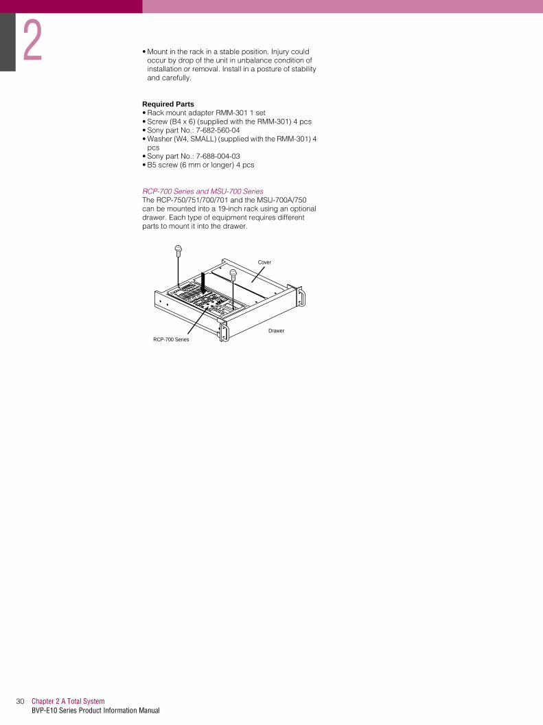
RCP-700 Series and MSU-700 SeriesThe RCP-750/751/700/701 and the MSU-700A/750 can be mounted into a 19-inch rack using an optional drawer. Each type of equipment requires different parts to mount it into the drawer.
2
RCP-700 Series
Drawer
Cover

BVP-E10 Series Product Information Manual
13 Benefit of Sony ADSP (Advanced Digital Signal Processing)

3
Chapter 3 Benefit of Sony ADSP (Advanced Digital Signal Processing)BVP-E10 Series Product Information Manual
32
3-1. Full DSP Camera ProcessingThe BVP-E10 Series uses 12-bit A/D conversion together with Advanced Digital Signal Processing (ADSP) based on the latest generation of digital LSI technology to deliver superb SDTV images. ADSP provides a number of innovative and powerful control
functions, increasing the creative tools available to camera users. ADSP also takes advantage of several techniques to maximize the performance of the digital processing, in order to exploit the wide dynamic range given by the Power HAD EX CCD sensor
3-2. Maximum Dynamic Range(1) Optimized bit assignmentIn the BVP-E10, video signals up to 260% of white level is processed linearly. Highlights over 260% are compressed by a pre-knee circuit before A/D conversion, providing the most efficient utilization of the 12-bit A/D conversion process.
(2) Auto Knee
The BVP-E10 Series uses a digital knee circuit to increase the dynamic range which can be captured by the camera. When the Auto Knee button on the MSU or RCP panel is pressed, the ADSP circuitry automatically optimizes both the knee point and knee slope for best reproduction of the high lights. Auto Knee can also be used in conjunction with The Adaptive Highlight control function described later .
Figure 3-2-1: Auto Knee curve image
(3) Adaptive highlight control (Auto Knee mode)Conventional cameras only have a single knee point/ slope characteristic. In contrast, the Sony ADSP system has multiple knee point/slope characteristics. The camera monitors the brightness of all areas of the picture and adapts the knee point/slope for optimum reproduction. A typical example is shooting an interior scene which includes a sunlit exterior seen through a window. This new function applies only to video levels in excess of the knee point, the middle and low luminance parts remaining unchanged, ensuring camera matching is not impaired.
Figure 3-2-2: Knee curve image
Input signal level
Output signal level
white clipauto slope
point limit
auto knee circuit
white clip
auto slope
knee
poi
nt 0
knee
poi
nt 1
knee
poi
nt 2
knee
poi
nt 3
knee
poi
nt n
Output signal level
Intput signal level
........

33Chapter 3 Benefit of Sony ADSP (Advanced Digital Signal Processing)BVP-E10 Series Product Information Manual
Photo 3-2-1: Adaptive highlight control ON and OFF
Normal ON
3-3. Other ADSP Functions(1) Knee SaturationConventional cameras can reduce colour saturation in highlight areas, resulting in a 'washed out' effect and hue changes in overexposed areas of a picture. The Sony ADSP system maintains colour in highlight areas, , providing more natural colour reproduction. A Knee Saturation control allows manual adjustment of highlight saturation.
Photo 3-3-1: Knee Saturation ON and OFF
Normal
ON
(2) Low key saturationWith conventional cameras, low light areas can be subject to a reduction in saturation. This can result in colour in these areas being "washed out". The Low Key Saturation function on the BVP-E10 Series eliminates
this problem by optimizing the amplification of colour saturation at low light levels, providing more natural colour reproduction. In addition, the Low Key Saturation Range control offers a choice of 4 ranges defining the range of the Low Key Saturation control
Photo 3-3-2: Low Key Saturation ON and OFF
Normal
(3) GammaNew 12-bit A/D conversion more precisely defines the required gamma characteristic by using a gamma curve created from 48 segments. This is in comparison with the 32 segments in the previous camera range.
(4) Black GammaBlack Gamma allows control of the linear part of the gamma characteristic, providing adjustment of the shadow areas of the picture during shooting . As with Low Key Saturation, a Black Gamma Range control sets the range over which Black Gamma operates. In the lowest setting, Black Gamma only influences the lowest level parts of the video signal, while in the highest setting, control extends to 50% video.
washed out
Colorimetry in dark areas are improved.ON

3
Chapter 3 Benefit of Sony ADSP (Advanced Digital Signal Processing)BVP-E10 Series Product Information Manual
34
(5) Multi MatrixMulti Matrix is a function that electronically adjusts the basic RGB colour 'taking characteristics' of the camera to achieve optimum colorimetry. It makes it easy to match the colour of cameras under multi-camera operations, or to reproduce the characteristics of another type of camera. It can also be used to manipulate colour for a particular special effect. A conventional linear matrix function provides only six adjustable parameters, with considerable interaction between their effects on a specific colour. Multi Matrix divides the spectrum into 16 segments, each of 22.5 degrees, for each of which there is an independent hue and saturation parameter. Multi Matrix allows the selection of each of these segments, with separate adjustment of hue and saturation parameters.Operation flow is as follows:
1. Select Multi Matrix on the paint menu of the MSU- 700A/750 Master Set-up Unit.
2. Turn the Matrix and the Multi switches to ON.
3. The MSU-700A/750 EL display now shows a representation of the Multi Matrix as it would appear on a vectorscope. You can select the desired colour phase that you want to adjust. (note for simplicity, the representation is based on the NTSC vector display)
4. After selection of the colour phase, its hue and saturation can be adjusted.
Figure 3-3-1: Multi Matrix
Photo 3-3-3: Multi Matrix ON and OFF
Normal
On
Photo 3-3-4: Multi Matrix (Vectorscope)
Normar
ON
R-Y
B-Y
saturation
hue

35Chapter 3 Benefit of Sony ADSP (Advanced Digital Signal Processing)BVP-E10 Series Product Information Manual
(6) Triple Skin Tone Detail CorrectionSkin Tone Detail Correction controls the detail level of those objects which have specific colour tones. The BVP-E10 Series allows detail to be set independently for each of three separate colour ranges. Colours are not limited to skin tones, but can be set for any colour. Detail may be increased or decreased relative to the normal level.
Figure 3-3-2: Figure 3-3-2: Skin Tone Detail Correction
Photo 3-3-5: Triple Skin Tone Detail Correction ON and OFF
Normal
Phase : Sets the colour phase for which Skin Tone Detail Correction is activated.
Width : Sets the colour width for which Skin Tone Detail Correction is activated.
Saturation : Sets the saturation for which Skin Tone Detail Correction is activated.
R-YWidth
B-Y
Phase
Saturation
SofterCH-1 On
Sharper SofterCH-2 On

3
Chapter 3 Benefit of Sony ADSP (Advanced Digital Signal Processing)BVP-E10 Series Product Information Manual
36
(7) Adaptive Detail ControlThe Adaptive Detail Control provides natural detail enhancement on extreme highlights by automatically altering the amplitude of the edge signal for high contrast signals.
Photo 3-3-6: Adaptive Detail Control ON and OFF
MagnifiedNormal
The black edges are removed.On

37Chapter 3 Benefit of Sony ADSP (Advanced Digital Signal Processing)BVP-E10 Series Product Information Manual
(8) Electronic Soft FocusThis function is similar to an optical soft filter. By subtracting the edge enhancement signal from the original video signal, slightly 'defocused' pictures are created electronically. This is an important new creative feature, and - especially when used in conjunction with Skin Tone detail - can be used when more of a 'film look' is sought for close-ups, etc.
Figure 3-3-3: Electronic Soft Focus signal image
Photo 3-3-7: Electronic Soft Focus ON and OFF
Normal
Electronic Soft Focus On (Softer than with Detail Off)
Detail off
(9) Skin Tone Auto IrisA problem with a conventional auto iris is that movement of bright objects in a scene adversely affects facial exposure - a news studio is a typical example. Skin Tone Auto Iris is a function that controls the auto iris system to ensure a constant video level for a defined skin area within the scene. In the news studio example, when the colour phase is adjusted to match the facial tones of the newscaster, the iris now maintains the same video level even if the newscaster turns a page of their report, or people enter or exit the scene. It is effective for the other colours in addition to human skin tone.
Original
Enhancer
Soft Focus

3
Chapter 3 Benefit of Sony ADSP (Advanced Digital Signal Processing)BVP-E10 Series Product Information Manual
38
(10)3-D White Shading CorrectionThe camera picture area is divided into up to 1000 separate zones, each of which may have different shading value. The correction is automatically interpolated across adjacent zones. This technique provides precise white shading correction over the whole picture area. The 3D shading mode can be enabled through the camera maintenance menu, and operates automatically each time white shading is performed. Because the camera 'learns' and interpolates the data the accuracy may be improved still further on subsequent auto shading operations. White shading data should be stored in the camera OHB file or will otherwise be lost when the camera power is turned off.
Photo 3-3-4: Correction curve image
(11)Fine DetailThe Fine Detail function allows the width of the detail edge to be adjusted without changing the peak level.*
*Effective for H details only.
Figure 3-3-5: Signal curve image
(12)Cross Colour SuppressionSeparating the luminance and chrominance components of a composite signal can be a difficult task, even with the most advanced comb filtering techniques. In order to keep cross colour and cross luminance to a minimum, the BVP-E10 Series virtually eliminates frequency components that may result in such artifacts being generated prior to the signal output. These frequency components are eliminated
from the Y/R-Y/B-Y signals within the camera head by using sophisticated digital three line (NTSC)/five line (PAL)* comb filtering. This results in more greatly reduced cross colour and dot crawl than normally seen on a picture monitor fed from a composite video signal.
* three line for PAL on PsF mode
Conventional Correction
3D Shading Correction
fine DTL off fine DTL on

39Chapter 3 Benefit of Sony ADSP (Advanced Digital Signal Processing)BVP-E10 Series Product Information Manual
3-4. Outstanding reliability and easy maintenanceOne of the most important concerns for broadcasters is the reliability of equipment. This is considerably improved with Sony digital processing. In Sony ADSP cameras, all the processing parameters are completely and precisely defined at the design stage, and almost all the potentiometers are replaced by semiconductor memories. Consequently, Sony ADSP cameras show extremely stable performance, regardless of environmental conditions such as temperature, humidity, shock and vibration. This high stability, together with the advantages of the self-
contained menu system, enables easy and accurate set-up of camera systems for regular realignment. Finally, a great benefit of Sony ADSP cameras is their advanced self-diagnostic system. BVP-E10 Series cameras detect problems in their digital processing and provide a viewfinder warning indication. Detailed information, such as identifying the faulty board, is also shown on the Master Set-up Unit screen and the Camera Command Network Unit character display to provide easy and rapid fault location.
3-5. Low power consumptionThe BVP-E10 Series uses new digital techniques to significantly reduce the power consumption of the camera to just 13 Watts. This has the additional benefit of lowering the internal operating temperature of the camera, which further increases the stability of the signal processing circuitry, and provides increased operator comfort.


BVP-E10 Series Product Information Manual
14 Control System

4
Chapter 4 Control SystemBVP-E10 Series Product Information Manual
42
4-1. Sony Camera Control SystemSeveral decades of TV operations have led to the development of many alternative operational and engineering philosophies relating to the deployment of video and technical control and to the monitoring and routine maintenance of multi-camera studio and OB truck installations. Sony has re-examined the entire studio camera architecture with the goal of structuring a far higher degree of system flexibility. For many applications, the RCP-750/751 (see Figure 4-1-1) provides comprehensive control of all required parameters.
For more complex installations, the system offers several important features• High-speed communication of digital control
commands• A considerably augmented Master Set-up Unit, the
MSU-700A/750• The introduction of a powerful technical 'nerve
centre' concept - the camera Command Network Units, CNU-700 and CNU-500
• Electronically assignable camera remote control panels for use with these camera command network units
4-2. Master Set-up Unit - MSU-700A/750The Master Set-up Unit (MSU) is the centralized technical control position for multi-camera systems. The MSU-700A/750 has been designed to provide comprehensive and wide ranging technical supervision and alignment of a complex camera system from a single centralized panel. If it is desirable in a large programme origination complex to extend this supervision to more than one control location (for example, separate operational and engineering/ maintenance control centres) then a number of MSU-700A/750 units can access the entire camera system. To exercise maximum flexibility in controlling a multi-camera system, the MSU-700A/750 is designed to work in conjunction with the CNU-700 and CNU-500 Command Network Units. However, if a simplified system is desired, the MSU-700A/750 can also operate as a stand-alone unit. It provides rapid, fingertip access to all controls relating to the smooth functioning of an operational system, including:• Technical alignment controls for the entire camera
chain• Picture and waveform monitor switching• System configuration• Control data filing
Extended Technical Access to Camera Video ProcessingA traditional high-end studio/OB camera chain entails a multiplicity of technical adjustments. In combination they optimize of the technical alignment of the RGB video processing channels and allow a broad degree of control over certain critical video subsystems (such as image enhancement, colour reproduction, dynamic range, etc.). Typically, these technical controls are segregated into those requiring regular operational access - and are provided as remote adjustments on video operational panels or technical control panels - and others, perhaps requiring less frequent access, which are relegated to screwdriver adjustments on various circuit boards within the camera head and CCU. This separation often entailed a degree of protracted (and frustrating) re-alignment when subtle creative readjustments are desired for a particular picture composition.
In the BVP-E10 Series camera system, Sony has adopted the philosophy that all technical controls are important and that remote access to virtually all controls on a single control panel would bring higher operational efficiency. This led to the introduction of the MSU-700A/750 Master Set-up Unit. To avoid undue complication of the ergonomics of the panel layout that would result from such extensive access, a novel Electro Luminescent (EL) sub-panel forms an integral part of the overall MSU-700A/750 control panel - photo
4-1. This menu-driven touch screen allows remote pre-programmed and logical access to dozens of technical adjustments. The main features of the MSU-700A/750 are given below.
(1) Easy operation• The following modes can be easily accessed by
using the new EL touch panel display for maintenance and daily operation.
• Paint mode: Various paint items such as White, Black and Flare are adjustable
• File mode: Storing, retrieving and transferring reference files, lens files and scene files between camera heads on a PC memory card
• Maintenance mode: System phase control, CCU video level alignment, selection of character display from a CNU-700 and CNU-500, etc.
• Configuration mode: Entire control system configuration, RCP assignment, etc.
• Card mode: PC memory card initialize, store to PC memory card/recall from PC memory card, etc.
• Multi-mode: Setting of multi-camera operation such as 'All', 'Control Priority', 'Parallel Mode', etc.
• Function mode: On the MSU-750, this provides quick access to frequently used switch functions such as detail on/off, knee on/off etc. The MSU-700A includes dedicated front-panel switches for these functions
(2) Multi-MSU operationIn a conventional system, a single MSU controls a single studio or multiple studios. However, in this new control system, multiple MSUs can be used to remotely control/supervise a single studio from different operational engineering and control rooms.
(3) Standard switchThe user's standard operational setting is easily recalled by pressing the 'standard' switch.
Photo 4-2-1: MSU-700A/750A Master Set-up Unit

43Chapter 4 Control SystemBVP-E10 Series Product Information Manual
4-3. Camera Command Network Units - CNU-500/ 700 The CNU-700 and CNU-500 Camera Command Network Units are designed as the technical 'nerve centre' of a Star Shape Network System where all commands such as 'All', 'Control Priority', 'Parallel/ Mode', etc. are centralized and distributed to the respective CCUs of the studio system. They are furnished with an RS-232C port to provide interface capability to external systems such as ISR (Interactive Status Reporting), external PC or modem and robotics control systems. They can be mounted in a 19-inch standard rack (3U height for the CNU-700, and 1U height for the CNU-500).
By employing a RISC-based microprocessor in the CNU-700 and CNU-500, the communication speed has been greatly improved. Consequently, real-time control and instant response to the MSU-700A/750 or RCP-700 Series commands have been made possible.
Through a CNU-700 or CNU-500, one RCP can control one CCU while one MSU is able to control multiple CCUs. All units connected to the CNU can easily communicate with each other. Because of this useful new -function, simultaneous control of multi cameras, file transfers between multiple cameras and control from an external device are now possible. As a convenient tool for system set-up and maintenance, MSU control routing ,CNU control assignment, and other system information can be displayed on a conventional picture monitor.
Since the CNU is the nerve centre of a system, it has a bypass facility to maintain communication between the CCUs and RCPs in the event of a CNU malfunction or power loss. Therefore, even when the power unit or AT board of the CNU-700 or CNU-500 has failed, camera heads and HDCUs can be directly controlled from the RCPs to let programme production continue.
As mentioned in Section 2, Total System, the cost versus performance balance between the two types of Camera Command Network Units allows users to build up systems that meet their application needs. The CNU-500 is suitable for applications with up to six
cameras, while the CNU-700 can be expanded to handle up to 12 cameras with use of the BKP-7930 optional expansion board. By adding additional CNU-700s and BKP-7930 expansion boards, a large system of up to 96 cameras can be controlled.
(1) High-speed data transmission ratesCNU to MSU/RCP/ CCU: More than 500 Kbps (Approximately 50 times faster than earlier camera command systems)Camera Head to CCU: 35 Kbps (Approximately 15 times the speed of earlier analogue camera systems)
(2) System configurationBasic system: Up to six cameras with one CNU-700 or CNU-500Expanded system: Up to 12 cameras with one CNU-700 with one BKP-7930 optional board installedMaximum system: Up to 96 cameras with eight CNU-700 units (each with a BKP-7930 optional board installed) via I/O port on the rear panel (four MSU- 700A/750 Master Set-up Units required).
(3) Character displayInformation concerning the camera heads and CCUs connected to the CNU-700 and CNU-500 can be displayed on a monitor via the CHARACTER connector. This includes:• Camera settings• System connection information• Results of Auto set-up• Self-diagnostics information
(4) Emergency featureIn the event of a problem with the CNU-700 and CNU-500, turning their internal OPERATION switch to the EMERGENCY position allows control signals from the remote control panel to be directly connected to the camera head. In this way, programme production can continue by bypassing the CNU.
Table 4-3-1:A comparison between the CNU-700 and CNU-500
CNU-700 CNU-500
Number of Cameras connectableUp to 6 cameras
Up to 12 cameras with BKP-7930 fittedUp to 96 cameras with multi CNU connected
Up to 6 camerasNoNo
Number of RCPs connectableUp to 6 RCPs
Up to 12 RCPs with BKP-7930 fitted Up to 96 RCPs with multi CNU connected
Up to 6 RCPsNoNo
Multi MSU connectable Yes NoMulti VCS connectable Yes NoOther controller connectable Yes Available with optional AUX connectorProgramable with remote control Yes NoRS-232C connector for ISR Yes YesRS-232C connector for switcher etc.
OneTwo when BKP-7930 fitted
NoNo
REF. video in Yes YesCharacter out 2 1Assignment between RCP and CHU/CCU
Free Fixed
Power supply to RCPYes
(RCP power is maintained when CCU is switched off)
No(But RCP is powered from CCU)
Connect to previous generation's command system such as CCU-370 Yes, when BKP-7932 installed No
Height 3 U 1 U19-inch standard rack mauntable Yes Yes

4
Chapter 4 Control SystemBVP-E10 Series Product Information Manual
44
Figure 4-3-1: CNU-700/500 Basic System Configurations (Up to six cameras with one CNU-700 or CNU-500)
4-4. Remote Control Panels - RCP-700/ 701/ 750/ 751 RCP-700/701The RCP-700 (joystick type) and RCP-701 (dial control type) provide basic control of Iris, Master Black, and R/B black and white balance. They can be used in combination with the MSU-700A/750 where space is at a premium, or they can be used as a sub-control panel with other types of RCPs.
RCP-750/751The RCP-750/751 Remote Control Panel provides enhanced control of the Sony BVP-E10 Series Color Video Camera via the CCU-500/700/900Series Camera Control Unit. The panel is connected either directly to the CCU-500/700/900 Series Camera Control Unit or via the CNU-500/700 Camera Command Network Unit, by a special cable of up to 200 m (656 feet) in length.
The RCP-750 and RCP-751 are identical in their functions except with respect to the iris and master black adjustments, for which the RCP-750 uses a joystick type control while the RCP-751 uses rotary knobs.
The RCP-750/751 has the following features:Optimal control -arrangement for basic camera operationThis remote control panel is provided with all the essential control functions for normal operation of a BVP-E10 Series camera. The panel layout has been designed for efficient operation, and combines dedicated control switches and indicators for frequently used functions, together with a unique colour LCD touchscreen to provide rapid access to secondary operational and setup items.
BVP-E10/P/WS/WSP+CA-950/P+CA-905+BVF-77
CCU-900/P
VCS-700
MSU-700A
CNU-700/500
RCP-700 Series
Monitor
Waveform Monitor
VectorScope
B/W monitorfor characterdisplay
Command
Video
Character
1
2
3
4
5
6
NTSC orPAL
CCU-700/P
BVP-E10/P/WS/WSP+CA-570/P
CCU-550A/APW/BKP-5973

45Chapter 4 Control SystemBVP-E10 Series Product Information Manual
Controlling the scene file functionCamera adjustment and control data such as paint data for a particular scene can be stored in the camera in the form of a scene file. The stored data can easily be retrieved at any time to automatically set the camera to the shooting conditions for that particular scene. This panel enables up to five scene files to be created and handled.
Signal transmission via a digital lineBetween this remote control panel and the camera control unit, signals are digitally transmitted via a single connection cable (CCA-5), ensuring a reliable signal. Operating power is also supplied via the cable.
Memory Stick media card slotScene files, reference files, and other data can be stored on a Memory Stick media card and reproduced at any time.
Touch panel with 31/2-inch Colour LCD for various operationsThe control panel has a touch panel that permits various items to be selected and adjusted on the LCD in menu format.
Four units mountable on a 19-inch rackUp to four units of this control panel can be mounted across the width of a 19-inch EIA standard rack.
PreviewThe RCP-750 includes a joystick override (preview) function, activated by pressing down the joystick control knob. A connector on the RCP can be linked to an external router to provide camera preview selection. Alternatively, a menu setting in the RCP allows the preview function to control the camera selection of an MSU-700A/750, without requiring any external connecting cables.
Figure 4-4-1: Operation Panel of the RCP-750/751
IRIS/MBACTIVE
AUTO
RELATIVE
COARSE
SENS
OPENCLOSERELATIVE
MASTERBLACK
EXT
IRIS
EXT
IRIS/MBACTIVE
AUTO
COARSESENS OPENCLOSERELATIVE
MASTERBLACK
IRIS
PARA
STANDARDCHARACTER
MASTER SLAVE CAM PW
5600K
PAINT 1 PAINT 2
WHITE
ALARM CALL
REMOTE CONTROL PANEL
BLACK/FLARE a
PAINT 3 SCENE MAINTENANCE
FUNCTION
AUTOKNEE
SKINDETAIL
DTLGATE
BLACKGAMMA
TEST BARS CLOSE
LEVEL
AUTO SETUP
DETAIL
PANELACTIVE
SKIN DTLAUTO HUE
START/BREAK WHITE BLACK
ALARM CALL
REMOTE CONTROL PANEL
BLACK/FLARE a
PANELACTIVE
1Control select block q;Power and output signal select block
qaAUTO SETUP block
RCP-750
RCP-751
2STANDARD button
3Camera/CCU function ON/OFF buttons
4RGB WHITE controls
5RGB BLACK/FLARE controls and indicator6Camera number/tally indication window
7ALARM indicator8CALL button9PANEL ACTIVE button
6Camera number/tally indication window
7ALARM indicator8CALL button9PANEL ACTIVE button
qsMenu operation block
qfDETAIL knob
qgMEMORY STICK slot and access lamp
Iris/master black control block
Iris/master black control block

4
Chapter 4 Control SystemBVP-E10 Series Product Information Manual
46
4-5. Flexible System Configuration.In most camera systems, the physical cable connections determine which camera can be controlled from a given control panel. The Sony MSU/CNU/RCP system includes the facility to define the
camera selection by a control menu in the MSU. The configuration can also be graphically displayed on a monitor connected to the Character Display output from the CNU.
Figure 4-5-1: Flexible Configuration
- For flexibility, assignments can be easily changed e,g - CAM 1 controlles from RCP 1&2, CAM 2 controlled from RCP 3&4, CAM 3 controlles from RCP5, and CAM 5 controlled from RCP 6
BVP-E10/P/WS/WSP+CA-950/P+CA-905+BVF-77
CCU-900/P
Extremely Flexible Configuration- When ex-factory - The assignments between CCUs and RCPs are set as below.
1 CCU 1
2 CCU 2
3 CCU 3
4 CCU 4
5 CCU 5
6 CCU 6
VCS-700
CNU-700
MSU-700A
RCP-700 Series
RC
P 1
RC
P 2
RC
P 3
RC
P 4
RC
P 5
RC
P 6
BVP-E10/P/WS/WSP+CA-950/P+CA-905+BVF-77
CCU-900/P1 CCU 1
2 CCU 2
3 CCU 3
4 CCU 4
5 CCU 5
6 CCU 6
VCS-700
CNU-700
MSU-700A
RCP-700 Series
RC
P 1
RC
P 2
RC
P 3
RC
P 4
RC
P 5
RC
P 6
MSU 1
MSU 1
CCU-700/P
BVP-E10/P/WS/WSP+CA-570/P
CCU-700/P
BVP-E10/P/WS/WSP+CA-570/P

47Chapter 4 Control SystemBVP-E10 Series Product Information Manual
4-6. File StructureThe BVP-E10 Series camera system is able to store adjustment data in memory in the form of files. There are six types of files, for different purposes:
(1) Operator FileUsed to store viewfinder display preferences for the camera operator. There are many types of warning and information displays which can be superimposed on the viewfinder picture. These can be customized to suit individual preferences, and stored as an Operator File on a Memory Stick media card at the camera head. Video (painting) data is not stored in the Operator File
(2) Preset Operator FileStores the preset operator file items. This file is stored in the camera.
(3) Scene FileUsed for storing settings for frequently used operating environments. The scene file stores paint data for each scene, and up to five scene files can be stored in the
BVP-E10 system. Scene files can also be stored in the Memory Stick media card
(4) Reference FileUsed for storing the standard operating settings for a user. The reference file stores reference data used in the auto set-up mode plus the standard settings of those switch functions that are not executed with the auto set-up mode. A reference file is usually created when the camera is installed, and then left unchanged This file is stored in the camera and Memory Stick media card.
(5) Lens FileThe lens file contains data to compensate for various errors induced by the lens, including the Range Extender setting. In the case of the latest generation of digital lenses, the lens type is automatically selected, while for earlier generation lenses, the lens type can be selected by the user using the camera head. Lens files usually contain factory data, but can be modified by users if required.
Table 4-6-1:Structure of Paint Related Files
* The additional data of each file is sent to each circit on the unit.
File Storage and transfer Reference, Scene and Lens file information is stored in the camera head, but can be accessed through the camera control system. The MSU-700A and MSU-750 include a PC Card slot, which accepts a small PCMCIA-standard PC memory card The complete setting of a camera, including reference file and scene files, can be stored in this card for security. Memorized parameters can be accurately retrieved at any time and from any camera.
The MSU-700A/750 also include a file transfer function, which allows reference file and scene file
data to be transferred between cameras,. In a multi-camera operation system, optimum picture matching is simply and easily achieved by transferring the appropriate camera setting data from the master camera to other slave cameras via the CNU-700 or CNU-500. Thus, any camera can be set to a uniform condition once a master camera is specifically adjusted.
In simpler systems without MSU or CNU, the RCP-750/751 allows scene file and reference file data to be stored on a Memory Stick. File transfer between cameras can be carried out by manually transferring the Memory Stick to each RCP in turn.
4-7. Auto Set-upThe BVP-E10 Series cameras incorporate a sophisticated Auto Setup system to adjust the video processing circuitry parameters for optimum colour matching. In addition to auto white balance, auto black balance and auto level set-up, the following parameters can also be adjusted according to a reference file.• Auto white shading (The shading compensation is
achieved with horizontal and vertical saw tooth and
parabolic waveform as well as with a digitally synthesized waveform for almost 1000 individual correction zones created by DSP.)
• Skin detail auto hue (automatic hue detection for specified colour range, with full skin detail function.)
When STANDARD is executed.
Reference FileRefer to "File Items".
Factory-set value 0
Scene FileRefer to "File Items".
Lens FileWhen lens extender setting is OFF, Flare R/G/B and V Modulation Shading R/G/B/Master can be stored.
When lens extender setting is ON, White R/B, Flare R/G/B and V Modulation Shading R/G/B/Master can be stored.
OHB FileR/G/B for each White Shading H SAW, H PARA,
V SAW, VPARA can be stored.R/G/B for each Black Shading H SAW, H PARA, V SAW, and
V PARA can be stored.And OHB matrix and the ND offset can be stored.
Output to hardware*

4
Chapter 4 Control SystemBVP-E10 Series Product Information Manual
48
4-8. Control Priority and Parallel ModeControl PriorityWhen a camera system is configured using the CNU-700 or CNU-500, each camera can be connected in parallel to both an RCP-700 Series Remote Control Panel and the MSU-700A/750 Master Setup Unit, and is controlled from whichever unit has control priority. Priority for iris/master black adjustments only can be obtained when the IRIS/MB ACTIVE button on the panel on which the PANEL ACTIVE button is not lit. When the MSU-700A/750 is in the panel active status, only the iris and master black controls are inoperative
on the MSU-700A/750 and can be set by pressing the illuminated IRIS/MB ACTIVE button.
Parallel ModeThe MSU-700A/750 and RCP-700 Series panels have a PARA button to select Parallel Mode. When the PARA button of the unit is pressed and illuminated, Parallel Mode is activated and all the control functions, other than the iris/master black controls, become operative from both units. The Parallel Mode can be canceled by pressing the PARA button of the MSU-700A/750 or RCP-700 Series control panel.
4-9. S-BUS ControlThe S-Bus ConceptA further advantage of the Sony camera control system is the 'S-Bus control' technique, which is based on an original Sony concept. Studio installations and OB units use digital routers as the nerve centre for a complete audio/video system. With Sony system integration, all the equipment is connected to the Sony digital router via a LAN, called the 'S-BUS'. With the S-Bus system, control and tally signals are interlocked so that they, along with video and audio signals, can be simultaneously switched from a central terminal. Each input/output source can be given a name, which can then be displayed on the source name display panel of a DVS-9000 Series or MVS-8000 Series Video Switcher
or on the BKSR3280/ R3281 Status Character Display. One example of the operational advantages of the S-Bus system is that the routing of input signals to the primary inputs - of a DVS-9000/MVS-8000 Series Video Switcher can be changed at any time without having to re-connect cables. Even the source name display, tally signal and tally display are interlocked and changed automatically.
Sony camera command system with S-BusControlling the router from an MSU panelThe digital router's cross point can switched from the MSU-700A/750 by pressing its camera select button. SDI video monitoring is enabled.
Figure 4-9-1: Router control from MSU
Interlocking the RCP Assignment and WFM/PIX AssignmentWhen the assignment of any RCP is changed from the MSU-700A/750, the picture and waveform monitoring is also automatically changed to follow the new arrangement.
PIX CNU character
CCU-900/P with A/D board
CCU-700/P with A/D board
CCU-700/P with A/D board
CNU with BKP-7933
PIX WFM
Router(DVS-V3232 etc.)Primary Station
SDI
IN1
IN2
IN5 OUT25
SDI Monitorfrom MSU camera select
MSU-700A
S-BUS BNC
CCA-5
Video BNC
NTSC or PAL

49Chapter 4 Control SystemBVP-E10 Series Product Information Manual
Figure 4-9-2: Interlocking RCP and monitor assignment
Controlling the router from an RCPPressing the preview switch on an RCP-750/751 control panel switches the appropriate digital router
cross point. SDI video monitoring is enabled.(software preview function mustr be enabled in the RCP-750/751 menu)
Figure 4-9-3: Router control from an RCP
Controlling the RCP assignment from other S-BUS equipmentAll S-BUS equipment detects the connection configurations between camera heads, CCUs and RCPs by communicating with each other. This means that other S-BUS equipment can change the assignment of RCPs in a system that does not include an MSU-700A/750
PIX WFM
5CAM monitor
1CAM monitor
Control 5CAM
Control 1CAM
PIX WFM
4CAM monitor
2CAM monitor
Control 4CAM
Control 2CAM
PIX WFM
3CAM monitor
3CAM monitor
Control 3CAM
Control 3CAM
PIX WFM
2CAM monitor
4CAM monitor
Control 2CAM
Control 4CAM
PIX WFM
1CAM monitor
5CAM monitor
Control 1CAM
Control 5CAM
When the RCP assignment is canged, PIX/WFM video isalso changed automatically.
PIX CNU character
CCU-900/Pwith A/D board
CCU-700/Pwith A/D board
CCU-700/Pwith A/D board
CNU with BKP-7933
PIX WFM
Router(DVS-V3232 etc.)Primary Station
SDI
IN1
IN2
IN5
OUT1
OUT2
OUT5
SDI Monitor for RCP
MSU-700A
S-BUS BNC
CCA-5
Video BNC
PIX WFM
PIX WFM
NTSC or PAL

4
Chapter 4 Control SystemBVP-E10 Series Product Information Manual
50
Figure 4-9-4: Remote control of the RCP assignment without an MSU-700A/750
Camera name display onto CNUSony uses a PC as the primary control station of a digital router. Each camera can be given a name with this primary PC, and these names are then automatically shown on the CNU character display.
Serial Tally TransferDecodes S-BUS serial tally signal and forward to CCU.
A CNU-700 requires a BKP-7933 option for S-BUS functionality.
Figure 4-9-5: Current tally and S-BUS tally
S-BUS BNC
CCA-5
Video BNC
CCU
CCU
CCU
PIX WFM PIX WFM PIX WFM
PIXCNU with BKP-7933
PIX1
PIX1
PIX1
(IN1 to 5) PIX1 video in(IN13 to 17)WF1 video in(OUT1 to 5)PIX1 video out(OUT13 to 17)WF1 video outCNU
character
WF1
WF1
PIX/WF Monitor for RCP
WF1
IN1
IN2
IN5
IN13IN14
IN17
OUT1
OUT2
OUT5
OUT13
OUT14
OUT17Router(DVS-V3232 etc.)Primary Station
RCPRemote Assign
Panel
NTSC or PAL
CCUCCUCCU CCU
CNUCNU
CCA-5 cable
RS-422AS-BUSS-BUS
Tally DecoderTally Decoder
RS-422A
AUXBUS
Current TallyS-BUS Tally
BLACK COLOR
BKGDSHIFT
M/E
1
M/E
2
SHIFT
AUX DELEGATION
AUX
AUX AUX AUX AUX AUX AUX EDIT FRAMEMEM
1
FRAMEMEM
2
M/E1 M/E2AUX AUX AUX AUX AUX AUX AUX
KEY KEY WIPE DMECHR
TOP MENU
BKGD
TRANS
WIPE DMECHR BKGD
TRANS
KEY KEY
WIPE DMECHR BKGD
TRANS
DSK DSK P/P P/PDSKDME
FRAMEMEN
2
KEYPROG DISK STILL CHR
SETUP
BKGD FREZE PIC VIDEO IN
NON-GRAPH
LIGHT DME DME
FRAMEMEN
1
DLAG
M/E-1
M/E-2
UTILITY
SYSTEM
1
2
3
4
5
SHIFT
STATS
PATERN
MODIFY1
MODIFY2
DIRECTPOSIT
USERWIPE
F1 F2 F3 F4 F5 F6 F7 F8 F9 F10 EXIT
KEYPAD
KEYPAD
KEYPAD
KEYPAD
WIDTH
LUM
SAT
HUE
BLACK COLOR
BKGDSHIFT
BLACK COLOR
BKGDSHIFT
BLACK COLOR
BKGDSHIFT
BLACK COLOR
BKGDSHIFT
BLACK COLOR
BKGDSHIFT
BLACK COLOR
BKGDSHIFT
M/E
2
M/E
2
M/E
M/E
1
M/E
1
M/E
1
M/E
2
M/E
1
M/E
2
M/EM/E
ON
OVER
ON
OVER
BKGDDSK DSK
2
DSK DSK2KEY
MIX NAMSUPER
WIPE
AUTO CUT
FRAMES TRANSITION TYPE
NEXT TRANSITION
ON
OVER
ON
OVER
BKGDKEY KEY
2KEY
MIX NAMSUPER
WIPE
AUTO CUT
FRAMES TRANSITION TYPE
NEXT TRANSITION
ON
OVER
ON
OVER
BKGDKEY KEY
2KEY
MIX NAMSUPER
WIPE
AUTO CUT
FRAMES TRANSITION TYPE
NEXT TRANSITION
KEY2
KEY
MATTE AUTOSPLIT BORD
DROPSHDW
OUT
LUM LIN CLEAN CHR PTNKEY PROC
KEY KEY KEY KEY
1 2 3 4
KEY1 KEY2
KEY CONTROLXPT KEY
SHIFT
DME
WIPE
SNAP
SHOT0
1 2 3
4 5 6
7 8 9
EFF
DISS
AUTO
TRANS
KEY2
KEY
MATTE AUTOSPLIT BORD
DROPSHDW
OUT
LUM LIN CLEAN CHR PTNKEY PROC
KEY KEY KEY KEY
1 2 3 4
KEY1 KEY2
KEY CONTROLXPT KEY
SHIFT
DME
WIPE
SNAP
SHOT0
1 2 3
4 5 6
7 8 9
EFF
DISS
AUTO
TRANS
M/E-1
K1
A
B
M/E-2
A
B
M/E
M/E
M/E
M/EM/E
K2
K1
K2
PGM/PST
DSK1
DSK2
PGM
P/P
UTIL
DSK
1
DSK
2 PGM/PST
MATTE AUTOSPLIT BORD
DROPSHDW
OUT
LUM LIN CLEAN PTNKEY PROC
DSK DSK DSK DSK
1 2
3 4
EFFSNAP
ALL
M/E
M/E
DME
MASTER E-FILE CONTROL PANEL
RCALL
STORE
LEARN
TRANS
RATE
0
1 2 3
654
7 8 9EFFDIS
CLR
AUTOTRANS
TRIM
XPTDSBL
ENTER
LASTXDSK1
1 2
3 4
DSK2
DOWN STREAM KEYER
DSK2
FADETO
BLACK
DSK1
DVS-7250system
PGM
DME1
DME2
DME1
DME2
DME1
DME2
DME
1
DME
2
DME
3
DME
4
USER
P/PDSK
PST
AUXBUS
BLACK COLOR
BKGDSHIFT
M/E
1
M/E
2
SHIFT
AUX DELEGATION
AUX
AUX AUX AUX AUX AUX AUX EDIT FRAMEMEM
1
FRAMEMEM
2
M/E1 M/E2AUX AUX AUX AUX AUX AUX AUX
KEY KEY WIPE DMECHR
TOP MENU
BKGD
TRANS
WIPE DMECHR BKGD
TRANS
KEY KEY
WIPE DMECHR BKGD
TRANS
DSK DSK P/P P/PDSKDME
FRAMEMEN
2
KEYPROG DISK STILL CHR
SETUP
BKGD FREZE PIC VIDEO IN
NON-GRAPH
LIGHT DME DME
FRAMEMEN
1
DLAG
M/E-1
M/E-2
UTILITY
SYSTEM
1
2
3
4
5
SHIFT
STATS
PATERN
MODIFY1
MODIFY2
DIRECTPOSIT
USERWIPE
F1 F2 F3 F4 F5 F6 F7 F8 F9 F10 EXIT
KEYPAD
KEYPAD
KEYPAD
KEYPAD
WIDTH
LUM
SAT
HUE
BLACK COLOR
BKGDSHIFT
BLACK COLOR
BKGDSHIFT
BLACK COLOR
BKGDSHIFT
BLACK COLOR
BKGDSHIFT
BLACK COLOR
BKGDSHIFT
BLACK COLOR
BKGDSHIFT
M/E
2
M/E
2
M/E
M/E
1
M/E
1
M/E
1
M/E
2
M/E
1
M/E
2
M/EM/E
ON
OVER
ON
OVER
BKGDDSK DSK
2
DSK DSK2KEY
MIX NAMSUPER
WIPE
AUTO CUT
FRAMES TRANSITION TYPE
NEXT TRANSITION
ON
OVER
ON
OVER
BKGDKEY KEY
2KEY
MIX NAMSUPER
WIPE
AUTO CUT
FRAMES TRANSITION TYPE
NEXT TRANSITION
ON
OVER
ON
OVER
BKGDKEY KEY
2KEY
MIX NAMSUPER
WIPE
AUTO CUT
FRAMES TRANSITION TYPE
NEXT TRANSITION
KEY2
KEY
MATTE AUTOSPLIT BORD
DROPSHDW
OUT
LUM LIN CLEAN CHR PTNKEY PROC
KEY KEY KEY KEY
1 2 3 4
KEY1 KEY2
KEY CONTROLXPT KEY
SHIFT
DME
WIPE
SNAP
SHOT0
1 2 3
4 5 6
7 8 9
EFF
DISS
AUTO
TRANS
KEY2
KEY
MATTE AUTOSPLIT BORD
DROPSHDW
OUT
LUM LIN CLEAN CHR PTNKEY PROC
KEY KEY KEY KEY
1 2 3 4
KEY1 KEY2
KEY CONTROLXPT KEY
SHIFT
DME
WIPE
SNAP
SHOT0
1 2 3
4 5 6
7 8 9
EFF
DISS
AUTO
TRANS
M/E-1
K1
A
B
M/E-2
A
B
M/E
M/E
M/E
M/EM/E
K2
K1
K2
PGM/PST
DSK1
DSK2
PGM
P/P
UTIL
DSK
1
DSK
2 PGM/PST
MATTE AUTOSPLIT BORD
DROPSHDW
OUT
LUM LIN CLEAN PTNKEY PROC
DSK DSK DSK DSK
1 2
3 4
EFFSNAP
ALL
M/E
M/E
DME
MASTER E-FILE CONTROL PANEL
RCALL
STORE
LEARN
TRANS
RATE
0
1 2 3
654
7 8 9EFFDIS
CLR
AUTOTRANS
TRIM
XPTDSBL
ENTER
LASTXDSK1
1 2
3 4
DSK2
DOWN STREAM KEYER
DSK2
FADETO
BLACK
DSK1
DVS-7250system
PGM
DME1
DME2
DME1
DME2
DME1
DME2
DME
1
DME
2
DME
3
DME
4
USER
P/PDSK
PST

BVP-E10 Series Product Information Manual
15 Optical Fibre Transmission System

5
Chapter 5 Optical Fibre Transmission SystemBVP-E10 Series Product Information Manual
52
5-1. Optical Fibre OverviewThe wide band triax system provided by the CA-570/P and CCU-550D/DP and CCU-700A/P ensures robust, accurate video and audio transmission from camera head to CCU. However, the alternative Fibre ttansmission system employed in the CA-950/P and CCU-900/P provides several important benefits. • Long distance transmission. Video and audsio
signals can be transmited up to 3 km (1.86 miles)* including power. If power is supplied locally at the camera head, maximum distance is extended to 10 km (6.24miles)
• Fully digital transmission. 4:2:2 component video signals are transmitted between camera head and CCU, ensuring very high quality.
• No performance degradation even at long cable lengths. Unlike conventional triax systems, video quality is not affected by cable length. Full facilities, including teleprompter and return viewfinder video are maintained up to maximum cable length.
To provide the high-quality signal transmission between the CCU-900/P and BVP-E10 Series, the SMPTE standard optical fibre connector and cable have been adopted. The connecting cable uses two single-mode optical fibre lines, two control lines, and two power lines to carry digitized video, audio, control signals and power to the camera.
* When supplying power to the camera via the optical fibre cable, the maximum cable length varies with the camera system configuration and lens type, the size of the optical fibre cable and the number of cable connectors.
5-2. Cleaning of the Connector and CableThe optical contacts of the fibre interface are vulnerable to dust and dirt, so care should be exercised to avoid unnecessary exposure to any contamination. In particular, the dust covers supplied should always be ued when the cable is disconnected.
Regular cleaning of the optical contact of the units mentioned below is strongly recomended• CCU connector of CA-905/P• Camera connector of the CCU-900/P• Optical/Electrical cable
When using the BVP-E10 Series with the large lens adaptor CA-905L, it is recommended to also clean the following optical items.• CA cable • CCU connector
Follow the procedures below for cleaning.
Tools Required• Alignment sleeve remover HC-001 (for female
connector)Sony P/N: J-6480-010-A
NoteInsert the shorter nose end when removing/installing the alignment sleeve.Grasp the handle, not the shock absorber.
• Cotton swabs (commercially available)
NoteUse the cotton swab with a diameter of around 4 mm. The cotton swab with a diameter more than 5 mm does not reach far enough in to the inner part of the cable, to clean the tip of the optical contact.
Cleaning
Male connectorClean the tip of the white optical contacts with a cotton swab moistened with alcohol.
Female connectorThe optical contacts for the female connector are in an unexposed area. When cleaning, it is necessary to expose the contacts by first removing the alignment sleeve. Proceed as follows.
1. Insert the alignment sleeve remover into the alignment sleeve in a straight line and turn it clockwise.
2. When the turning stops, forcedly pull out the remover in the straight line.NoteThe alignment sleeve can be removed/reinstalled with the sleeve itself attached to the tip of the remover.
Insert the shorter nose end
Shock absorber portion Handle
Optical contacts (white)

53Chapter 5 Optical Fibre Transmission SystemBVP-E10 Series Product Information Manual
Great care should be taken so as not to lose or damage the alignment sleeve.(Alignment sleeve: Sony P/N 9-980-074-01)
3. Clean the tip of the white optical contacts with a cotton swab moistened with alcohol.
4. Insert the remover with the alignment sleeve attached to its tip, and push it until it clicks.
5. Rotate the remover counterclockwise to install the alignment sleeve, and extract the remover.
Alignment sleeve
Optical contacts (white)


BVP-E10 Series Product Information Manual
16 A Quick Lesson onCamera Settings

6
Chapter 6 A Quick Lesson on Camera SettingsBVP-E10 Series Product Information Manual
56
6-1. Camera SettingsAlthough accurate alignment and matching of cameras generally requires skilled and experienced operators, for day-to-day operation the automatic functions included in the BVP-E10 series cameras, and the stability provided by the digital processing allow excellent picture quality to be maintained without skilled operatorsThe following information may be used as a guide for such operation.
1. One-touch power onUse the main switch of the power supply to turn on/off the whole system rather than using the power on/off switches on the individual devices for operating convenience.
2. Warm-up timeA camera system can be used to start shooting within a few seconds after power is turned on. If the camera is connected in a large system environment, it may require a little more time especially for System Locking after the power is turned on. It is recommended that system components that need continual system stability, such as a sync-generator, should remain powered on at all times.
3. Camera head connection(1) When the camera head connection needs to be
changed, turn off the HEAD POWER using the switches on the CCU or RCP.
(2) Check the cable indicator on the CCU. If the Cable "Open" LED is illuminated, ensure that the cable is correctly connected at both ends. If the cable "Short" LED is illuminated, the cable may be faulty. Do not use until the problem has been rectified.
(3) When changing the accessories such as a lens or viewfinder, it is possible to turn the camera power off using the POWER SW on the camera adaptor. Ensure this is switched back on when the change is completed
4. InstallationWhen cameras are first installed, the standard operating conditions (knee, matrix, gamma etc) should be stored in the camera reference file. These settings can then be quickly recalled just by pressing the Standard button. This clears any adjustments which may have been made by another operator.
5. Scene filesFor settings which will be used frequently (different studio lighting settings, for example), scene files should be created. These settings can then be quickly recreated by a single button press.
6. Camera adjustment(1) Press the STANDARD button to clear the data
from the last shooting, or execute Auto Setup.(2) Perform an Auto Black balance(3) Perform an auto white balance using a gray
scale or standard white chart. in the same lighting conditions that will be used for programme shooting. Ensure the chart is uniformly illuminated.
7. Precise camera adjustment(1) For more precise adjustment of the camera, a
grey scale chart is recommended- Check the gray scale for any stains, spots, cracks, or imperfections. Old, damaged or discoloured chart should not be used. (Keep the chart at normal room temperature in a dark area to prolong its useful life).
(2) Accurate alignment can only be made if the waveform monitor and picture monitor used are themselves accurately maintained.
(3) CCU and system check Switch on Colour bars, and ensure the colour bar level and black balance of each camera is the same level. Any discrepancies point to errors in the monitoring system, or in the alignment of the CCU, and should be eliminated before attempting camera adjustments.
(4) Gray scale check View the grey scale chart, and monitor using picture and waveform monitors. Use the iris control to adjust the white level to 100%. Execute Auto White or adjust RGB WHT to make the R/G/B levels match. This can be done using the RGB selection from the waveform monitoring, or by viewing the composite output from the camera and checking that there is no chroma present
(5) The grey scale should be uniform, with negligible chroma on any of the steps. Precise adjustments of Flare, Black Level and Gamma can all be made in this way, but require skill and experience, and are outside the scope of this document.
8. Colour matching between the camerasEven after making the above camera adjustments, there still might be a very small difference between the cameras. This difference is usually so slight that it can be ignored. However, if it is desired to make a closer match, then this should be achieved by Choosing one camera as a reference and adjusting the levels of black, gamma and flare of the other cameras to match those of the chosen reference camera.
NotesBe sure to situate each camera as close as possible to each other because the reflected light from the test chart changes depending on the angle of reflection even when shooting the same chart.
9. EndWhen shooting is finished, just turn off the main switch of the CCU power supply. When powered up next time, the camera will return to exactly the same condition as before switch off

BVP-E10 Series Product Information Manual
17 Location and Function of Parts and Controls

7
Chapter 7 Location and Function of Parts and ControlsBVP-E10 Series Product Information Manual
58
7-1. BVP-E10 Series, Color Video Camera
7-1-1 Side Panels
aaaa Handle buttonsThe function of each of these buttons is assignable in the menu operation. At the factory, the frontbutton is set to RET 1, and the rear button is set to INCOM.RET 1 (return video 1): A return video 1 signal from the Camera Control Unit (CCU) is displayed on the viewfinder screen while this button is pressed.INCOM (intercom): The intercom microphone is ON while this button is pressed.
bbbb Viewfinder lock leverLocks the viewfinder after adjusting the position in the front-to-rear direction together with the LOCK knob.
cccc Assignable buttonThis switch can be assigned by the user to different functions as required. The setting can be changed with the OPERATION Menu. On the BVP-E10/E10P, a electronic colour temperature correction of 5,600K is the default factory setting for this button. On the BVP-E10WS/E10WSP, the default setting is unassigned. Set the function with the OPERATION Menu as required.
VTR
GA
IN
OU
TPU
T
WH
ITE
BA
L
STATUS
CANCELMENU
GENLOCKDISPLAY
ONOFF
MENU
RE
T1
INC
AM
TESTOUT
MIC
1Handle buttons
2Viewfinder lock lever
3Assignable button
4ND filter selector
5CC filter (BVPE10WS/ E10WSP only)
6WHITE BAL switch
7OUTPUT/DCC switch
8GAIN switch
9VTR switch
q;STATUS/CANCEL switch
qaDISPLAY switch
qsMemory Stick slot
qdCA lock screw
qfLOCK knob
qgViewfinder lock ring
qhTEST OUT connector
4ND filter selector

59Chapter 7 Location and Function of Parts and ControlsBVP-E10 Series Product Information Manual
dddd ND filter selectorSelects the desired ND filter.
eeee CC (colour temperature conversion) filter (BVPE10WS/ E10WSP only)
Selects the desired CC filter suitable for the lighting conditions. Note that in the BVP-E10/E10P cameras, electronic colour temperature correction is used instead of an optical filter.
ffff WHITE BAL (white balance memory select) switch
Selects the white balance adjustment method and memory cell to store the adjusted value.
PRESET: White balance is automatically adjusted to the preset value for the colour temperature of 3,200K.A or B: Memory cell A or B is selected.
gggg OUTPUT/DCC (output signal select/auto knee) switch
Selects an output signal supplied to a VTR, viewfinder, and video monitor (colour-bar signals or camera picture). When a camera picture is selected, the auto knee function can be activated.
BARS/OFF: Colour-bar signals are output, and the autoknee circuit does not function.CAM/OFF: A camera picture is output, but the auto-knee circuit does not function.CAM/ON: A camera picture is output, and the auto-knee circuit functions.
hhhh GAIN switchSelects the appropriate video gain (Low, Medium, High) according to the illumination of the subject to be shot. The actual gain values for positions L, M, and H, are set with the OPERATION Menu.
iiii VTR switchWhen a portable VTR is connected to the camera via the CA-530/570/570P/950/950P Camera Adaptor, the VTR starts recording as follows:
SAVE: Power-save position for recording. Recording starts a few seconds after the VTR START button is pressed. A newly recorded picture may not smoothly be connected to the previously recorded part.
STBY (standby): Recording starts immediately upon pressing the VTR START button.
Note:The WHITE BAL, OUTPUT/DCC, GAIN, and VTR switches do not function when the camera is connected to a Camera Control Unit (CCU), RCP or Remote Control Unit (RM).
jjjj STATUS/CANCEL switchSTATUS: Displays the setting status of the camera on the viewfinder screen when the switch is set to this position after setting the DISPLAY switch to ON.CANCEL: Cancels the selection made by the MENU SELECT knob and restores the previously selected menu item.
kkkk DISPLAY switchUsed for displaying the current status of the camera, settings of format and assignable buttons, and menu on the viewfinder screen.
ON: Display function activatedOFF: Display function not activatedMENU: A screen for setting the displaying items and functions appears.
llll Memory Stick slotInsert a Memory Stick to store file data.
mmmm CA lock screwTighten the screw to secure the CA-530/ 570/5 70P/ 950/ 950P Camera Adaptor to the camera.
nnnn LOCK knobLocks the viewfinder after adjusting the position in the front-to-rear direction together with the viewfinder lock lever.
oooo Viewfinder lock ringLocks the viewfinder after adjusting the position side to side.
pppp TEST OUT connector (BNC type)Supplies the signal selected with the menu operation or the remote control panel.
Filter No. Filter
1 Clear
2 1/4ND
3 1/16ND
4 1/64ND
Filter No. Filter
A Cross filter
B 3,200K (Clear)
C 4,300K
D 6,300K

Chapter 7 Location and Function of Parts and ControlsBVP-E10 Series Product Information Manual
7
60
7-1-2 Front Panel
aaaa VF (viewfinder) connector (20-pin)Connect the 20-pin viewfinder cable of the BVF-10/10CE/ 20W/ 20WCE viewfinder.
bbbb Cable clampSecures a microphone cable and lens cable.
cccc Lens mount leverSecures the lens to the lens mount.
dddd AUTO W/B BAL (automatic white balance/ black balance adjustment) switch
Adjusts the white balance and black balance automatically.
WHT: The white balance is automatically adjusted. When the WHITE BAL switch on the side of the camera is set to A or B, the adjusted value is stored in memory cell A or B.BLK: The black balance is automatically adjusted. The black set is simultaneously adjusted.
Note:The SHUTTER and AUTO W/B BAL switches do not function when the camera is connected to a CCU, RCP, or RM.
eeee MENU SELECT knobWhen the DISPLAY switch on the side panel is set to MENU and the menu is displayed, turn this control to select a menu item and press it to register the selection.
ffff MIC LEVEL (microphone level) controlWhen a portable VTR is connected using the CCZ cable of the CA-570/570P Camera Adaptor, the microphone level can be adjusted by turning this control. When the CA-570/570P Camera Adaptor is used and the LEVEL/ MIC switch on the rear panel of the camera adaptor is set to FRONT/OFF, the sound volume of the intercom can be adjusted using this control.
gggg SHUTTER switchOFF: Electronic shutter does not function.ON: Electronic shutter is activated.SEL: The shutter speed and shutter mode change each time the switch is set to this position.
hhhh VTR START buttonWhen a Camera Control Unit (CCU) is connected, the audio signal of the intercom is sent to the CCU while this button is held pressed. When a VTR is connected using the CCZ cable of the CA-570/570P, pressing this button starts recording, and pressing it again stops recording. It is the same function as with the VTR button on the lens.
iiii LENS connector (12-pin)Connect a lens cable.
jjjj MIC (microphone) connector (3-pin)Connect a microphone cable. Normally, connect the microphone supplied with the BVF-10/ 10CE/ 20W/ 20WCE Viewfinder. Phantom powering is turned off with the appropriate internal switch setting.
VF
VTR START
AUTO W/B BAL
MICLEVEL
WHT
BLK
OFF
ON
SEL
SHUTTER
LENS
1VF connector
2Cable clamp
3Lens mount lever
4AUTO W/B BAL switch
5MENU SELECT knob
6MIC LEVEL control
7SHUTTER switch
8VTR START button
9LENS connector
q;MIC connector

61Chapter 7 Location and Function of Parts and ControlsBVP-E10 Series Product Information Manual
7-2. CA-570/ 570P, Camera Adaptor
aaaa RET1 (return video 1) button/RET (return video) button and RET 2/3/4 switch
RET1 (return video 1) buttonPress this button to monitor the return video1 signal from the CCU in the viewfinder or on a monitor using the TEST OUT signal .RET (return video) buttonPress this button to monitor the return video signal from the CCU in the viewfinder. Select the monitored signal with the RET 2/3/4 switch.
RET 2/3/4 switchSelects the return video signal displayed in the viewfinder while the RET button is pressed.
bbbb TALLY lamp and TALLY switchIf the TALLY switch is ON, the TALLY lamp illuminates when a red tally signal or call signal is input to the CCU. Turning S200-1 on the AU-251 board to ON mixes and outputs the battery alarm signal to the TALLY lamp.
1RET1 button/RET button and RET 2/3/4 switch
2TALLY lamp and TALLY switch
3PGM level controls and PROD/ENG switches
4INCOM level controls, PROD/ENGswitches, and LEVEL MIC switches
CA-570
5Triax connector
6INCOM 1/2 connectors
7VTR connector
8REMOTE connector
9DC IN connector
q;PROMPTER/GEN LOCK
qaAUDIO IN 1/AUDIO IN 2 connectors and LINE/MIC switch and external power supply modeswitch mode switch for the microphone
qsTEST OUT connector
qdRET CONT connector
qfTRACKER connector
qgEARPHONE jack
qhCALL button
qjPOWER switchqkDC OUT connector
qlPGM level control
w;ENG level control
waMIC LINE switch
wsPROD level control
wdTRACKER level control
wfLEVEL/MIC switch

Chapter 7 Location and Function of Parts and ControlsBVP-E10 Series Product Information Manual
7
62
c PGM (programme) level controls (for the CA-570)Adjusts the audio volume of the programme.NotePGM level controls are provided for both intercom 1 and 2.
dddd INCOM (intercom) level controls, PROD/ENG (producer/ engineer) switches, and LEVEL MIC (intercom level/microphone) switches (for the CA-570 . For CA-950P, see later section)
INCOM (intercom) level controlsAdjusts the audio volume of the intercom.PROD/ENG (producer/engineer) switchesSwitches the intercom line.
PROD: Selects the producer’s lineENG: Selects the engineer’s line
LEVEL/MIC (intercom level/microphone) switchesThe LEVEL and MIC switch settings specify the following functions:REAR/ON: Turns on the intercom microphone. Adjust the intercom reception level with the INCOM control.
REAR/OFF: Turns off the intercom microphone. Turn the intercom microphone on and off using the control on the external equipment connected to the RET CONT connector. Adjust the intercom reception level with the INCOM control.FRONT/OFF: Turns off the intercom microphone. Turn the intercom microphone on and off using the control on the external equipment connected to the RET CONT connector. Use the control on the camcorder to adjust the intercom reception level.
NoteINCOM level controls and LEVEL/MIC switches and PROD/ENG switches are provided for both intercom 1 and 2.
eeee Triax connectorConnects a CCU-700A/700AP or CCU-550/550P Series Camera Control Unit through a triax cable.
ffff INCOM (intercom) 1/2 connectorsConnects headphones to enable the reception of programme/intercom audio and transmission of intercom audio. Set the MIC switch on the AU-237 board to "CM" when using a headset with carbon-type microphone, and set it to "DYN" when using a dynamic microphone. The INCOM 1 connector can be used for communications even though the power to the camera is turned off on the CCU-700A/700AP or CCU-550/ 550P.
gggg VTR connector (26-pin)Provides inputs and outputs of video signals, audio signals, control signals, and the power supply. Connects with the CAMERA connector on a VTR or AC adaptor.NoteThe VTR connector cannot be used when a CCU is connected.
hhhh REMOTE connector (8-pin)Allows connection of an RCP-700 Series or RM-B150/750 Remote Control Unit. The length of the connecting cable should not exceed 150 feet (50 metres).Note• The REMOTE connector cannot be used when a
CCU is connected.• When connecting the RM-B150/750, use the cable
supplied with the panel.
iiii DC IN (direct current input) connector (4-pin)Connects 12 volts DC supply from an AC adapter or battery case. Supplies power to the CA-570/570P when the POWER switch is set to EXT.
jjjj PROMPTER/GEN LOCK (prompter signal and external sync signal input) connector (BNC type)
Multi purpose connector. Provides an external sync signal input or prompter video signal output, or a reverse prompter input. Select the respective function with the PROMPTER/GENLOCK switch on the internal MD-119 board. The connector is factory set for PROMPT.
kkkk AUDIO IN 1/AUDIO IN 2 (audio input) connectors (XLR type, 3-pin) and LINE/MIC (line input/microphone) switch
Accepts external audio signals. Set the LINE/MIC switch according to the input signal level. The following phantom power supply settings can be specified for the external microphone:• +12V phantom power is supplied to the external
microphone (when the S800 switch on the AU-251 board is set to ON).
OFF: No power is supplied to the external microphone.+48V: +48V phantom power is supplied to the external microphone. (when the S700 switch on the AU-251 board is set to ON).Note: care should be taken that phantom power should only be used with suitable microphones. Incorrect settings could result in damage to the microphone
llll TEST OUT (test video output) connector (BNC type)
Outputs return video signals, playback video signals, VBS signal, or monitor output signals. Normally outputs return video signals when a CCU is connected, and playback video signals when a VTR is connected.NoteSelect the output signal with switch S100 on the AU- 251 board.
mmmm RET CONT (return control) connector (6-pin)Accepts the control signal for selecting the return video and for remotely turning the intercom microphone on and off.
nnnn TRACKER connector (10-pin)Use for communications with a tracker, crane operator or other external location. Provdes a private communications channel as well as intercom 1 and 2 communications. Also outputs12 volts DC, Red and Green tally and programme audio signals. The maximam output current output from this connector is 500 mA.
oooo EARPHONE jack (mini-jack)Connects an earphone for monitoring the audio from the VTR, the intercom, or the programme. Select the audio source with the switch S1 on the MB-783 board.
pppp CALL buttonUse this button to call the CCU or MSU operator. When this button is pressed, the red tally lamps in the viewfinder and on the camera control unit (CCU) or master setup unit (MSU) light up.
qqqq POWER switchSelects the power supply.
1 CCU: Power is supplied from the CCU.a (standby): Standby mode\EXT: Power is supplied from the VTR or EXT DC IN connector.

63Chapter 7 Location and Function of Parts and ControlsBVP-E10 Series Product Information Manual
rrrr DC OUT (direct current output) connector (4-pin)Outputs a direct DC voltage of 10.5 V to 17 V at a maximum rated current output of 500 mA, for use with radio microphone receivers and similar equipment. Connecting equipment with a power consumption greater than the maximum rating will activate the protection circuit, cutting off the current flow.
ssss PGM (programme) level control (for the CA-570P)
Adjusts the volume of the programme audio.
tttt ENG (engineer) level control (for the CA-570P)*Adjusts the volume of the engineering talkback.
*Only when used with CCU-700AP. The CCU-550DP has simplified intercom facilities, and provides only a single switched intercom channel. The volume is controlled by the PROD volume control, and selection of Production or Engineering talkbsck is made using the Mic Line Switch (21)
uuuu MIC LINE switch (for the CA-570P)PROD: Enables intercom microphone and routes talkback to Production.OFF: Turns off the intercom microphone.ENG: Enables intercom microphone and routes talkback to Engineering.
vvvv PROD (engineer) level control (for the CA-570P)*Adjusts the volume of the production talkback.
w RACKER (engineer) level control (for the CA-570P)Adjusts the audio volume of the tracker.
xxxx LEVEL/MIC (intercom level/microphone) switch (for the CA-570P)
The LEVEL and MIC switch settings specify the following functions:
REAR/ON: Turns on the intercom microphone. Adjust the intercom reception level with the PGM level control, ENG level control, PROD level control, or TRACKER level control.REAR/OFF: Turns off the intercom microphone.Turn the intercom microphone on and off using the control on the external equipment connected to the RET CONT connector. Adjust the intercom reception level with the PGM level control, ENG level control, PROD level control, or TRAKER level control.FRONT/OFF: Turns off the intercom microphone. Turn the intercom microphone on and off using the control on the external equipment connected to the RET CONT connector. Use the control on the camcorder to adjust the intercom reception level.

Chapter 7 Location and Function of Parts and ControlsBVP-E10 Series Product Information Manual
7
64
7-3. CA-950/ 950P, Camera Adaptor
aaaa PGM 1 (programme 1)/PGM 2 (programme 2) switch
Switches programme audio 1 and 2.
bbbb RET 1 (return video 1) button/RET (return video) button and RET 2/3/4 switch
RET 1 (return video 1) buttonPress this button to monitor the return video 1 signal from the CCU in the viewfinder or on a monitor using the TEST OUT signal.
5NCOM level controls, PROD/ENG switches, andLEVEL/MIC switches
4PGM level controls
1PGM 1/PGM 2 switch
CA-950P CA-950
2RET 1 button/RET button and RET 2/3/4 switch
waENG level control
1PGM 1/PGM 2 switch
2RET 1 button/RET button and RET 2/3/4 switch
3TALLY lamp and TALLY switch
qgEARPHONE jack
qfTRACKER connector
qdRET CONT connector
qsTEST OUT connector
qhCALL button
qjPOWER switch
qkSERIAL IN connector
qlSERIAL OUT connector
w;DC OUT connector
wsPGM level control
wdMIC LINE switch
wfPROD level control
wgTRACKER level control
whLEVEL switch
6CCU connector
7 INCOM 1/INCOM 2 connectors
8REMOTE connector
9DC IN connector
q;PROMPTER/GEN LOCK onnector
qaAUDIO IN 1/AUDIO IN 2 connectors and LINE/MIC switch/External Mic/Power Supply mode switch

65Chapter 7 Location and Function of Parts and ControlsBVP-E10 Series Product Information Manual
RET (return video) buttonPress this button to monitor the return video signal from the CCU in the viewfinder. Select the monitored signal with the RET 2/3/4 switch.RET 2/3/4 switchSelects the return video signal monitored in the viewfinder while the RET button is pressed.
cccc TALLY lamp and TALLY switchIf the TALLY switch is ON, the TALLY lamp illuminates when a red tally signal or call signal is input to the CCU. Turning S1 on the IF-633 board to ON mixes and outputs the battery alarm signal to the TALLY lamp.
d PGM (programme) level controls (for the CA-950)Adjusts the audio volume of the programme.NotePGM level controls are provided for both intercom 1 and 2.
eeee INCOM (intercom) level controls, PROD/ENG (producer/ engineer) switches, and LEVEL/MIC (intercom level/ microphone) switches (for the CA-950. For CA-950P, see later section)
INCOM (intercom) level controlsAdjusts the audio volume of the intercom.PROD/ENG (producer/engineer) switchesSwitches the intercom line.
PROD: Selects the producer's lineENG: Selects the engineer's line
LEVEL/MIC (intercom level/microphone) switchesThe LEVEL and MIC switch settings specify the following functions:
REAR/ON: Turns on the intercom microphone. Adjust the intercom reception level with the INCOM control.REAR/OFF: Turns off the intercom microphone. Turn the intercom microphone on and off using the control on the external equipment connected to the RET CONT connector. Adjust the intercom reception level with the INCOM control.FRONT/OFF: Turns off the intercom microphone. Turn the intercom microphone on and off using the control on the external equipment connected to the RET CONT connector. The intercom reception level is adjusted with the control on the camcorder.
NoteINCOM level controls and LEVEL/MIC switches and PROD/ENG switches are provided for both intercom 1 and 2.
ffff CCU connectorConnect a CCU-900/900P-series Camera Control Unit through an optical fibre cable.NoteA dual camera system or a stand-alone operation is not activated when an optical fibre is connected to this connector.
gggg INCOM 1 (intercom 1)/INCOM 2 (intercom 2) connectors
Connect a headset to enable the reception of programme/ intercom audio and transmission of intercom audio. Set the INCOM 1, INCOM 2 switches on the AU-237 board to "CM" when using a headset with carbon-type microphone, and set it to "DYM" when using a dynamic-type microphone.The INCOM 1 connector can be used for communications even though the power to the camera is turned off on the CCU-900/900P.
hhhh REMOTE connector (8-pin)Allows connection of an RCP-700 Series or RM-B150/B750 Remote Control Unit for stand-alone operation.
The length of the connecting cable should not exceed 150 feet (50 metres). Also used for connecting the remote cable of a CA-905L/F.Note• Do not connect an RCP-700 Series panel or an
RMB150/70 when a CCU is connected.• When connecting the RM-B150/750, use the cable
supplied with the panel.
iiii DC IN (direct current input) connector (4-pin)Connects 12 volts DC supply from an AC adapter or battery case. Supplies power to the CA-950/950P when the POWER switch is set to EXT
jjjj PROMPTER/GEN LOCK (prompter signal and external sync signal input) connector (BNC type)
Multi purpose connector provides an external sync signal input, or prompter video signal output, or a reverse prompter input. Select the respective function with the PROMPTER/GENLOCK switch on the internal DPR board. The connector is factory set for prompter video signal output.
kkkk AUDIO IN 1/AUDIO IN 2 (audio input) connectors (XLR type, 3-pin) and LINE/MIC
(line input/microphone) switchAccepts external audio signals. Set the LINE/MIC switch according to the input signal level.The following phantom power settings can be specified for the external microphone:
OFF: No power is supplied to the external microphone.+48V: +48V phantom power is supplied to the external microphone.
llll TEST OUT (test video output) connector (BNC type)
Outputs return video signals, playback video signals, VBS signal, or monitor output signals. Normally outputs monitor output signals when a CCU is connected.NoteSelect the output signal with switch S1 on the IFF-633 board.
mmmm RET CONT (return control) connector (6-pin)Inputs the control signal for selecting the return video and for remotely turning the intercom microphone on and off.
nnnn TRACKER connector (10-pin)Use for communications with a tracker, crane operator or other external location. Provides a private communications channel as well as intercom 1 and 2 communications. Also outputs 12 volts DC, the red and green tally signals and programme audio signals. The maximum output current output from this connector is 1 A. RS-232C input and output signals are also available to provide bi-directional data transmission between camera and CCU at up to 9600 bps with the CCU- 900/900P Camera Control Unit.
oooo EARPHONE jack (mini-jack)Connects an earphone for monitoring the audio from the programme.
pppp CALL buttonUse this button to call the CCU or MSU operator. When this button is pressed, the red tally lamps on the camera control unit (CCU) or master setup unit (MSU) light up.

Chapter 7 Location and Function of Parts and ControlsBVP-E10 Series Product Information Manual
7
66
qqqq POWER switchSelects the power supply.
1CCU: Power is supplied from the CCU. The indicator illuminates green.a(standby): Standby mode. The indicator illuminates red.\EXT: Power is supplied from EXT DC IN connector. The indicator illuminates green. The indicator blinks red when the internal temperature of this unit becomes abnormally high. The indicator blinks slowly green when the optical signal that reaches the cable adapter through the optical fibre cable is low (-17 to -20 dBm), and blinks rapidly green when the optical signal is very low (less than -20 dBm).
rrrr SERIAL IN (serial digital video signal input) connector (BNC type)
Accepts a component serial digital signal synchronized with the camera system, this signal is transmitted to the AUX OUT connector of the CCU through the optical fibre cable. In the case of dual camera link system, connect this connector with the SERIAL OUT connector of the secondary CA-950/950P.
For setting of dual camera link, refer to the installation manual supplied with the CCU-900/900P.
When using the camera stand alone, leave this connector unconnected.
ssss SERIAL OUT (serial digital video signal output) connector (BNC type)
Outputs a component serial digital signal input to the AUX IN connector of the CCU. In the case of dual camera link, connect to the SERIAL IN connector of the secondary CA-950/950P. When using the camera as stand alone, camera image signal is output from this connector.
tttt DC OUT (direct current output) connector (4-pin)Output DC voltage of 10.5 V to 17 V at a maximum rated current output of 500 mA, for use with radio microphone receivers and similar equipment. Connecting equipment with a power consumption greater than the maximum rating will activate the protection circuit, cutting off the current flow.
u PGM (programme) level control (for the CA-950P)Adjusts the audio volume of the programme audio.
vvvv ENG (engineer) level control (for the CA-950P)Adjusts the audio volume of the engineering talkback.
wwww MIC LINE switch (for the CA-950P)PRODEnables intercom microphone and routes talkback to ProductionOFF: Turns off the intercom microphone.ENG: Enables intercom microphone and routes talkback to Engineering.
xxxx PROD (producer) level control (for the CA-950P)Adjusts the volume of the production talkback.
yyyy RACKER level control (for the CA-950P)Adjusts the volume of the tracker.
zzzz LEVEL (intercom level) switch (for the CA-950P)REAR: Adjust the intercom reception level with the PGM level control, ENG level control, PROD level control, or TRACKER level control.FRONT: Use the control on the camera to adjust the intercom reception level.

67Chapter 7 Location and Function of Parts and ControlsBVP-E10 Series Product Information Manual
7-4. CCU-550D/ 550DP, Camera Control Unit
7-4-1 Front Panel
aaaa Camera number /tally indicatorIlluminates red when the red tally signal is input (e.g. when the video signal from the video camera connected to the CCU-550D/550DPCCU-550D/550DP goes on air). When the CALL button on the video camera, MSU-700A/750, RCP-700 Series remote control panel, or an optional BKP-5973 is pressed, he indicator lights if it is not lit, and goes off if it is lit. the indicator lights green when the green tally signal is input. Attach the appropriate number from the supplied number sheet here to indicate the camera number.
bbbb POWER switch/CAM (camera) and MAIN indicators
The POWER switch turns on or off the power supply to the entire camera system, including the CCU-550D/550DPCCU-550D/550DP, the video camera, and the remote control unit connected to the REMOTE connector on the CCU-550D/550DPCCU-550D/550DP. The MAIN and CAM indicators light when the POWER switch is turned on. The CAM indicator goes off when the power is turned off by the CAM PW button on the remote control panel or the master setup unit, or CAM POWER switch on the internal AT board.NoteIf the fan in the CCU-550D/550DP stops, the MAIN and the CAM indicators will flash simultaneously to warn you of the abnormal condition. If this occurs, turn the POWER switch off immediately and contact Sony service personnel.
cccc CABLE ALARM indicatorsOPEN: Illuminates when no triax cable is connected to the CAMERA connector on the rear panel of the CCU-550D/550DP, or when the load current is extremely low even when a camera cable is connected.SHORT: Illuminates when there is a current overflow in the triax cable.
dddd INCOM (intercom) input/output/setting section INCOM (intercom) connector (XLR, 5-pin)
Connects a headset. When you wish to use a headset with a plug other than XLR 5-pin type, consult Sony service personnel.INCOM level controlAdjusts the volume level of the intercom.MIC/PGM (programme audio) switch
ON: Turns on the headset microphone.OFF: Turns off the headset microphone.PGM: Outputs the programme audio. When this position is selected, the INCOM level control adjusts input level of the programme audio.
INCOM selectorSelects the pathway of intercom signals output/input through the INCOM/TALLY/PGM connector.
PROD: Producer line.PRIV: Producer line and engineer line are cut off and communication is possible only between the CCU-550D/550DP and the camera connected to the rear panel of the CCU-550D/550DP.ENG: Engineer line.
POWER
INCOM
CABLEALARM
?
1
CAM
ON PROD
PGM PGM
MIC –
OFF PREV
OPEN
SHORT
MAIN
1Camera number/tally indicator
2POWER switch/CAM and MAIN indicators 3CABLE ALARM indicators
4INCOM input/output/setting section

Chapter 7 Location and Function of Parts and ControlsBVP-E10 Series Product Information Manual
7
68
7-4-2 Rear Panel
aaaa CAMERA connector (triax connector)Connects to the CA-570/ 570P/ 905K/ 905F Camera Adaptor attached to the BVP-E10 Series Color Video Camera using a triax cable.NoteDo NOT use a defective triax cable. The inner sheath of a triax cable is used for power supply and the outer sheath for safety ground. For your safety, do NOT use a triax cable whose inner and outer sheaths are short-circuited. Use of such a cable may cause electric shock.
bbbb MIC (microphone) OUTPUT connectors (XLR, 3-pin)
Supply the microphone signals from the video camera.
cccc INPUT connectorsREFERENCE INPUT connectors (BNC type)Accept reference signals (black burst signal) for external synchronization.RET 1/RET 2 (return video signal 1/2) connectors (BNC type)Accept return video signals from two different sources.PROMPTER/RET 3 (return video signal 3) connectors (BNC type)Accept a teleprompter signal or a return video signal. Use the switch on the internal DM board to select PROMPTER or RET 3.
dddd OUTPUT connectorsY/G, Cr/R, Cb/B (component video signal /RGB output) connectors (BNC type)Supply the analogue component signals or the R, G, and B signals for a video switcher, VTR or chroma keyer from each connector. Use the switch on the internal VA board to select the signals to be output.VBS1/2/3 (composite video signal 1/2/3 output) connectors (BNC type)Supply the signal from the video camera in composite format. Use the switch on the internal VA board to select the composite video signal or sync signal. When
the sync signal (0.3 Vp-p, 75 ohms) is selected, connect the VBS 3 connector to the sync signal input connector on a waveform or picture monitor.WF (waveform monitor output) connector (BNC type)Supplies a video signal to a waveform monitor. The WAVEFORM MONITOR button on the optional MSU-700A/ 750 Master Setup Unit, MONITOR SELECT function on the RCP-750/751 Remote Control Panel, or MONITOR SELECT control on the BKP- 5973 CCU Control Panel selects the signal output from the WF connector. WF MODE (waveform monitor mode) connector (4-pin)Connects to the corresponding connector on a waveform monitor to allow the sequential monitoring of signals.PIX (picture monitor output) connector (BNC type)Supplies a video signal or video and character signals together to a picture monitor.Use the PICTURE MONITOR button on the MSU-700A/ 750, MONITOR SELECT function on the RCP-750/751, or MONITOR SELECT control on the BKP-5973 to select the signal output from the PIX connector.
eeee SERIAL OUTPUT (serial digital video/audio output) connectors (BNC type)
Supply the video/microphone signals from the video camera in serial digital format. CCU-550D/550DPConnect to a digital video switcher or component digital VTR.
ffff MIC REMOTE (microphone remote control) connector (D-sub, 15-pin)
Connects to an external control unit such as an audio mixer. With the connected unit, you can set the microphone input level of the video camera to -60, -50, -40, -30, or -20 dB. You can also set the microphone input level with a switch on the internal AT board.
MIC OUTPUT
INPUT
SERIAL OUTPUT
OUTPUT
COAX
RET 1 R-Y/R
REFERENCE Y/G VBS3 VBS1
RET 2 B-Y/B
WF VBS2
WF MODE
PROMPTER/RET 3 PIX
MIC REMOTE REMOTEINTERCOM/TALLY/PGM
CAMERA
CH-1 CH-2
RCP/CNU
1CAMERA connector 2MIC OUTPUT connectors3INPUT connectors
4OUTPUT connectors5SERIAL OUTPUT connectors
9COAX connector
8RCP/CNU REMOTE connector
7INTERCOM/TALLY/PGM connector6MIC REMOTE connector
q;AC IN connecto

69Chapter 7 Location and Function of Parts and ControlsBVP-E10 Series Product Information Manual
gggg INTERCOM/TALLY/PGM (programme audio) connector (D-sub, 25-pin)
Inputs/outputs intercom, tally, and programme audio signals. Connects to an intercom, tally, or programme audio connector of an intercom system.
hhhh RCP/CNU REMOTE (remote control panel/ camera command network remote) connector (8-pin)
Connects to the MSU-700A/750 Master Setup Unit, CNU-700/500 Camera Command Network Unit, RCP-700 Series Remote Control Panel or RM-B150/750 Remote Control Unit with an optional CCA-5 connecting cable to transmit/receive control signals. When the remote control panel or the remote control unit is connected, power is supplied to the remote control panel or the remote control unit through this connector.
iiii COAX (coaxial) connector (BNC type)Accepts camera connection through a conventional coax cable instead of triax according to the setting of a switch on the internal DM board. Power is not supplied to the camera through this connector.
jjjj AC IN (AC power input) connectorConnects to an AC power source using the supplied AC power cord. Secure the power cord to the CCU-550D/550DP using the supplied plug holder.

Chapter 7 Location and Function of Parts and ControlsBVP-E10 Series Product Information Manual
7
70
7-5. CCU-700A/ 700AP, Camera Control Unit
7-5-1 Front Panel
aaaa Red tally lampIlluminates when the unit receives a red tally signal. When the CALL button on the video camera, MSU-700A Master Setup Unit, or RCP-700 Series Remote Control Panel is pressed, the lamp lights if it is not lit, or goes dark if it is lit. Attach a supplied number plate here.
bbbb Green tally lampIlluminates when the unit receives a green tally signal. Attach a supplied number plate here.
cccc MIC (microphone select) switchSet to the appropriate position according to the type of the headset microphone.
DYNAMIC: To use a dynamic microphoneOFF: To cut off a microphone signalCARBON: To use a carbon (or carbon equivalent) microphone.
The intercom line can be switched with the corresponding switch on the internal AT board.
dddd INTERCOM (intercom volume) controlAdjusts the receiving level of the intercom. The volume of the sound mixed with programme audio is set with the control on the internal AT board.
eeee INTERCOM connector (XLR 5-pin)Connect a headset. When you wish to use a headset with a plug other than XLR 5-pin type, consult an authorized Sony representative.
ffff CAMERA POWER switch and indicatorThis switch controls the power supply to the video camera when the MAIN POWER switch is set to the ON side (I position). The indicator illuminates when power is supplied to the video camera.If an RCP-700 Series Remote Control Panel is connected to this unit, the CAM PW switch on the panel must be lit for control of the power supply to the camera with this switch to be enabled.
gggg MAIN POWER switch and indicatorThis switch turns on and off the power supply to the entire camera system including this unit, a BVP-700/750/500/550-series Color Video Camera, and an RCP-700 Series Remote Control Panel connected to the REMOTE connector. The indicator illuminates when power is supplied to the system.
hhhh CABLE ALARM indicatorSHORT: Illuminates when there is a current overload in the triax cable or when there is a short-circuit in the unit.OPEN: Illuminates when no triax cable is connected to the CAMERA connector on the rear panel, when there is a faulty connection, or when load current is extremely low even if a camera cable is connected.
POWER POWERI
O
I
O
MAIN
1CABLEALARM MIC
CAMERA
INTERCOM
SHORT OPEN
DYNAMICOFFCARBON
CAMERA CONTROL UNIT
1
5INTERCOM connector
6CAMERA POWER switch and indicator
8CABLE ALARM indicator
7MAIN POWER switch and indicator
3MIC switch
4INTERCOM control
2Green tally lamp
1Red tally lamp

71Chapter 7 Location and Function of Parts and ControlsBVP-E10 Series Product Information Manual
7-5-2 Rear Panel
aaaa CAMERA connector (triax connector)Connect a BVP-E10-series Color Video Camera using a triax cable. All of the signals of the BVP-E10-series, such as the power, control, video, and audio, can be connected using a single triax cable. Various triax connector types are supported; please contact your local Sony office for details
Do NOT use a defective triax cable. The inner sheath of a triax cable is used for power supply and the outer sheath for safety ground. For your safety, do NOT use a triax cable whose inner and outer sheaths are short-circuited. Use of such a cable may cause electric shock.
bbbb MIC OUTPUT (microphone output) connectors (XLR 3-pin)
Supply the microphone signals from the video camera.
cccc RET1 through RET4 (return video 1 through 4 input) connectors (BNC type)
Accept the analogue return video signals from four different sources. To select the appropriate return signals use the RET1/RET buttons and RET2/3/4 switch on the CA-570/P.NoteWhen an optional BKP-7312 SDI input board is installed, nothing should be connected to the RET 1 and RET 2 connectors in the ANALOGUE INPUT block.
dddd REFERENCE (reference signal input) connectors (BNC type)
Accept a reference signal such as a black burst signal for external synchronization.
eeee PROMPTER (prompter signal input) connectors (BNC type)
Accept the signals for a teleprompter.
ffff R, G, and B (R, G, and B signal output) connectors (BNC type)
Supply the analogue R, G, and B signals for the video switcher, chroma keyer, or other destination from each connector.
gggg Y, Cr, and Cb (component video signal output) connectors (BNC type)
Supply the analogue Y, Cr, and Cb signals from each connector. Connect a VTR or a video switcher conforming to analogue component video signals.
hhhh CHARACTER (character signal output) connector (BNC type)
Supplies the self-diagnostic results of this unit as a video signal.
iiii WF1 and WF2 (waveform monitor 1 and 2 output) connectors (BNC type)
Supply the video signals for a waveform monitor. The MONITOR SELECT function on an RCP-750/751unit select the signal output from the WF 1 connector, and the WAVEFORM MONITOR buttons on the MSU-700A/750 select the signal output from the WF 2 connector.
jjjj PIX1 and PIX2 (picture monitor 1 and 2 output) connectors (BNC type)
Supply the video signals for a picture monitor. The MONITOR SELECT function on an RCP-750/751 unit select the signal output from the PIX 1 connector, and the PICTURE MONITOR buttons on the MSU-700A/750 select the signal output from the PIX 2 connector.
kkkk VBS1, VBS2, and VBS3 (composite video signal 1, 2, and 3 output) connectors (BNC type)
Supply composite video signals (VBS) from the video camera.
l SYNC (sync signal output) connector (BNC type)Supplies the sync signals (0.3 Vp-p, 75 ohms) generated by the built-in sync signal generator. Connect to the sync signal input connector of a waveform monitor or picture monitor.
mmmm AC IN (AC power input) connectorConnect to an AC power source using the supplied AC power cord. The power cord can be fixed to the CCU-700A/700AP using the supplied plug holder.
CCU-700P
110-120V
110-120V 220-240V
ÚAC IN
CAMERA
REMOTE INTERCOM/TALLY/PGM
MIC OUTPUT
RTS
CH-1 CH-2
MIC
INTERCOM
COAX DIGITAL VIDEO
SERIAL OUTPUTSERIAL INPUT
RET 1 REFERENCE R Y WF1 VBS1
RET 2 PROMPTER G R-Y PIX1 VBS2
RET 3 R B-Y WF2 VBS3
RET 4
RET 2RET 1 1 2 3
CHARACTER PIX2 SYNC AUX
RCP/CNU
WF MODE
INPUT OUTPUT
REMOTE
1CAMERA connector
2MIC OUTPUT connectors
3RET1 through RET4 connectors 4REFERENCE connectors 5PROMPTER connectorsANALOG INPUT block
ANALOG OUTPUT block6R, G, and B connectors 7Y, Cr, and Cb connectors
8CHARACTER connector9WF1 and WF2 connectorsq;PIX1 and PIX2 connectorsqaVBS1, VBS2, and VBS3 connectorsqsSYNC connector
qdAC IN connectorqfWF MODE connectorqgRCP/CNU REMOTE connector
qhAUX REMOTE connector
qjSERIAL OUTPUT 1, 2, and 3 connectorsqkSERIAL INPUT RET 1 and RET 2 connectors
DIGITAL VIDEO blockqlSpare connectors
w;COAX connectorwaINTERCOM/TALLY/PGM connector
wsRTS connectors wdINTERCOM REMOTE connector
wfMIC REMOTE connector
wgVoltage selector

Chapter 7 Location and Function of Parts and ControlsBVP-E10 Series Product Information Manual
7
72
nnnn WF MODE (waveform monitor mode) connector (4-pin)
Connect to the corresponding connector of a waveform monitor to monitor signals in sequential mode. A sequential control signal is output from this connector when you press the SEQ button on an RCP-700 Series unit, which enables simultaneous monitoring of the R, G, and B signals.
oooo RCP/CNU REMOTE (remote control panel/ camera command network unit remote control) connector (8-pin)
Connect an MSU-700A, MSU-750, CNU-700, or RCP-700 Series unit using a CCA-5 cable. Control signals are then accepted. When an RCP-700 Series unit is connected, the power is also supplied to the unit.
pppp AUX (auxiliary) REMOTE connector (8-pin)Connect an external system. For details on connections, refer to the authorized Sony representative.NoteIf you connect an RCP-700 Series unit to the RCP/ CNU REMOTE connector, this connector cannot supply power to the connected equipment.
qqqq SERIAL OUTPUT 1, 2, and 3 (serial digital video signal 1, 2, and 3 output) connectors (BNC type)
Signals sent from the video camera are converted into serial digital video signals and are supplied from these connectors. These connectors function when an optional BKP-7311 SDI output board is installed in the CCU-700A/700AP. Connect these connectors to the input connectors of a digital video switcher, component digital VTR, etc.
rrrr SERIAL INPUT RET 1 and RET 2 (serial digital return video signal 1 and 2 input) connectors (BNC type)
These connectors accept a 10-bit 4:2:2 component serial digital video signals as return video signals. They function when an optional BKP-7312 SDI input board is installed in the CCU-700A/ 700AP, and function as return video 1 and 2 input connectors.When the BKP-7312 is installed, nothing should be connected to the RET 1 and RET 2 connectors in the ANALOGUE INPUT block.
ssss Spare connectors (BNC type)
tttt COAX (coaxial) connector (BNC type)Accepts camera connection through a conventional coax cable instead of triax by setting a switch on the internal DM board. The unit cannot supply power to the video camera through this connector.When a return video function is used, the maximum cable length of a 5C-2V (RG-6A/U) coaxial cable is 800 m (2,624 feet).
uuuu INTERCOM/TALLY/PGM (programme audio) connector (19-pin)
Supplies and accepts intercom, tally, and programme audio signals. Connect to the corresponding connector on the intercom system.
vvvv RTS (RTS intercom) connectors (XLR 3-pin)Connect an RTS intercom system.
wwww INTERCOM REMOTE connector (D-sub 25-pin)Connect an external controller to control intercom muting, producer-line interruption, and engineer line interruption. This connector outputs the red tally, green tally, tally and call signals, and camera number.
xxxx MIC REMOTE (microphone remote control) connector (D-sub 15-pin)
Connect an external control unit such as an audio mixer. You can set the microphone input level of the video camera to -60, -50, -40, -30, or -20 dB with the connected unit. Set the microphone volume to the level suitable for shooting conditions. You can also set the microphone input level with the switch on the internal board of this unit. This connector outputs the red tally, and green tally signals.
yyyy Voltage selector (only for the CCU-700AP)The operating voltage of the CCU-700AP is set to 220 to 240 V AC at the factory. If the voltage of your local power line is different, change the setting of the voltage selector.

73Chapter 7 Location and Function of Parts and ControlsBVP-E10 Series Product Information Manual
7-6. CCU-900/ 900P, Camera Control Unit
7-6-1 Front Panel
aaaa Red tally lampIlluminates when a red tally signal is received. When the CALL button on the video camera, Master Setup Unit MSU-700A/750, RCP-700 Series Remote Control Panel, etc. is pressed, this lamp will go out if previously lit, and light up if previously off. A supplied number plate can be mounted here.
bbbb Green tally lampIlluminates when a green tally signal is received. A supplied number plate can be mounted here.
cccc MIC (microphone selection) switchUsed to select the type of headset microphone being used, or to turn microphone input off.
DYNAMIC: for a dynamic microphoneOFF: turns microphone input offCARBON: for a carbon or carbon equivalent microphone
dddd INTERCOM (intercom volume adjustment) control
Adjusts the intercom input level.
eeee CABLE ALARM indicatorSHORT: This indicator illuminates when there is a short circuit between a power supply line and the sheath of the optical-fibre cable, or when the two power supply lines are shorted. When this indicator illuminates, the power supply is shut off. (If the optical-fibre cable is long, this indicator may light for a few seconds after the main power is turned on until the short-circuit detection circuitry begins operating normally. This is not a malfunction.)OPEN: Illuminates when there is no camera connected via an optical-fibre cable to the CAMERA connector on the rear panel. The indicator blinks slowly when the optical signal level is in WARNING status, and blinks fast when it is in CARE status.
ffff MAIN POWER switch and indicatorTurns the power on or off for the entire system, consisting of the CCU-900/900P, a video camera, an RCP-700 Series Remote Control Panel connected via the REMOTE connector, etc. Setting the switch to the position turns the power on, and setting it to turns it off. The indicator is lit when the power supply is on.
gggg CAMERA POWER switch and indicatorTurns on/off the power to the camera head when the MAIN POWER switch is on. Setting the switch to the position turns the power on, and setting it to turns it off. When a remote control panel is connected, the power supply can be turned off with the CAM PW button on the remote control panel, but only when the switch on the CCU is in the "on" position
hhhh INTERCOM connector (XLR 5-pin)For connecting a headset. To use a headset with a plug other than an XLR 5-pin plug, consult a Sony service representative.
1Red tally lamp
2Green tally lamp
3MIC switch
4INTERCOM control
5CABLE ALARM indicator
6MAIN POWER switch and indicator
7CAMERA POWER switch and indicator
8INTERCOM connector

Chapter 7 Location and Function of Parts and ControlsBVP-E10 Series Product Information Manual
7
74
7-6-2 Rear Panel
aaaa CAMERA connector (optical-fibre connector)For connecting a video camera, using an optical-fibre cable such as the FC2-PD50/PD250. All video camera signals, including power supply, control, video, and audio, are sent and received with an optical-fibre cable.NoteDust on the connection surface of the optical-fibre cable may result in transmission errors. When not connected, always cover the end with the supplied cap.
bbbb SDI signal input/output connectors
A SERIAL RET INPUT 1 to 4 (SDI return video 1, 2, 3, and 4 input) connectors (BNC-type). Four independent SDI return video signals can be accepted. The selection of RET 1, 2, 3, or 4 is made using the return video switch on the camera. SDI and analogue return viewfinder inputs may be selected using the setup menu of the CCU-900/900P, or using the MSU-700A/750 Master Setup Unit. SDI AUX and PROMPTER inputs may also be used as return viewfinder input signals
B AUX IN (auxiliary input) connector (BNC-type). For dual camera operation, the primary and secondary CCUs are connected using the AUX IN/OUT connectors mutually. It is also possible
to use the AUX IN connector as an additional return viewfinder input
C AUX OUT (auxiliary output) connector (BNCtype). For dual camera operation, the primary and secondary CCUs are connected using the AUX IN/OUT connectors mutually.
D REFERENCE IN (reference input) connectors (BNC-type)Used to input a reference signal (sync or VS signal) for an external sync operation. Terminate the unused connector with a 75-ohm terminator.
E SERIAL OUTPUT 1 to 3 connectors (BNC-type)The signal from the video camera is output as three SDI signals
F SERIAL OUTPUT MONI (SDI monitor output) connector (BNC-type)The signal from the video camera mixed with the character signal, skin-tone gate signal, and 4:3 marker signal is output as an SDI signal.
NoteMixing is set to ON or OFF with the RCP-750/751 orMSU-700A/750 Master Setup Unit.
cccc Analogue signal input/output connectors
A RET INPUT 1 to 4 (return video 1, 2, 3, and 4 input) connectors (BNC-type)Four independent analogue return video signals can be accepted. The selection of RET 1, 2, 3, or 4 is made using the return video switch on the
1CAMERA connector 2SDI signal input/output connectors
3Analogue signal input/output connectors
BKP-9330(optional)
4AC IN connector
5Remote control connectors
6CHARACTER OUTPUT connector
7DIGITAL AUDIO connector
8AUDIO OUTPUT connectors
9INCOME REMOTE connector
q;INTERCOM/TALLY/PGM connector
6SERIAL OUTPUTMONI connector
5SERIAL OUTPUT 1 to 3 connectors
4REFERENCE IN connectors
3AUX OUT connector
2AUX IN connector
1SERIAL RET INPUT 1 to 4
1 2 3 4 1IN OUT 2 3 MONI
SERIAL RET INPUT AUX REFERENCE IN SERIAL OUTPUT
1 2 3 4 IN OUT PIX1WF1 WF2 PIX2
MONITOR OUT SYNC OUTRET INPUT PROMPTER
1RET INPUT 1 to 4 connectors
2PROMPTER IN connectors
3PROMPTER OUT connector4MONITOR OUT WF 1/WF 2 connectors
5MONITOR OUT PIX 1/PIX 2 connectors
6SYNC OUT connector

75Chapter 7 Location and Function of Parts and ControlsBVP-E10 Series Product Information Manual
camera. SDI and analogue return viewfinder inputs may be selected using the setup menu of the CCU-900/900P, or using the MSU-700A/750 Master Setup Unit, SDI AUX and PROMPTER inputs may also be used as return viewfinder input signals
B PROMPTER IN connectors (BNC-type)Used for prompter signal input. Terminate the unused connector with a 75-ohm terminator. An analogue signal of 1.0 Vp-p, 75-ohms is output via the PROMPTER OUT connector of a video camera with a frequency bandwidth of 5 MHz, regardless of signal format.
C PROMPTER OUT connector (BNC-type)Outputs the signals that are input via the PROMPTER IN connectors of the CCU-900/900P. These are analogue signals of 1.0 Vp-p, 75 ohms.
D MONITOR OUT WF 1/WF 2 (waveform monitor output 1/2) connectors (BNC-type)Supplies an analogue video signal for the waveform monitor selected with the MONITOR SELECT function on the RCP-750/751 Remote Control Panel or the WF MONITOR button on the MSU-700A/750 Master Setup Unit.
E MONITOR OUT PIX 1/PIX 2 (picture monitor output 1/2) connectors (BNC-type)Supplies an analogue video signal for a picture monitor selected with the MONITOR SELECT function on the RCP-750/751 Remote Control Panel, or the PICTURE MONITOR button on the MSU-700A/750 Master Setup Unit.
F SYNC OUT (sync signal output) connector (BNC-type)Supplies a composite sync signal from the internal sync signal generator.
dddd AC IN (AC power supply input) connectorConnect to an AC power supply using the supplied AC power cord. The power cord is fixed to the CCU-900/ 900P using the supplied plug holder.
eeee Remote control connectors
A AUX 1/AUX 2 (auxiliary 1/auxiliary 2) connectors (D-sub 9-pin, RS-422)Used to connect the CCU-900/900P and external equipment via an RS-422 interface.
B MIC REMOTE (microphone remote) connector (D-sub 15-pin)Using this connector, the video camera's microphone input level may be set from external equipment such as an audio mixer in five steps (-60, -50, -40, -30, and -20 dB). When recording, set the volume to an appropriate level for the
audio conditions. Also outputs red and green tally signals.Note: The microphone input level can
alternatively be set using switches on an internal board.
C WF MODE (waveform monitor mode) connector (D-sub 15-pin)Used to connect a cable from the appropriate connector on a waveform monitor when operating the waveform monitor display using an MSU-700A/ 750 Master Setup Unit or RCP-700 Series Remote Control Panel. When using a recall-type monitor, preset a display mode on the waveform monitor, and then recall the mode externally.
D WF MODE (waveform monitor mode output) connector (4-pin)Used to connect a cable from the appropriate connector on a waveform monitor when monitoring a signal in sequential mode. A sequence signal will be output when the SEQ button on the RCP-700 Series Remote Control Panel is pressed, allowing simultaneous monitoring of the R, G, and B signals in sequential mode.
E RCP/CNU connector (8-pin)Used to connect to an MSU-700A/750 Master Setup Unit, CNU-500/ 700 Camera Command Network Unit, or RCP-700 Series Remote Control Panel using a CCA-5 Connection Cable. Control signals are sent and received via this connector. When using an RCP-700 Series unit, power is also supplied.
F TRUNK LINE 1/TRUNK LINE 2 connectors (D-sub 9-pin, RS-232C)Used to connect the CCU-900/900P to the TRACKER connector (20-pin) on a CA-950/950P Camera Adaptor via an RS-232C interface. Allows bi-directional data communication with external equipment at the camera head. The RXD, TXD, RTS, and CTS signals can be transferred at up to 9600 bps using this connector. The TRUNK LINE 2 connector is provided for extension.
ffff CHARACTER OUTPUT (character signal output) connector (BNC-type)
Used to output the results of the CCU-900/900P diagnostic self-test and menu display in black-and white analogue video format.
gggg DIGITAL AUDIO (digital audio signal output) connector (BNC-type)
Used to output a digital audio signal input to the camera, or for output of the microphone signal converted to an AES/EBU-format digital audio signal.
hhhh AUDIO OUTPUT (audio signal output) connectors (XLR 3-pin)
Used to output the microphone signal or audio signal input to the video camera.
iiii INCOME REMOTE (intercom remote) connector (D-sub 25-pin)
Enables remote operation such as muting the intercom, break-in from the producer or from engineers by sending signals through this connector from external control equipments. Outputs red tally signal, green tally signal, tally call signal, and camera number signal.
AUX 1 WF MODE
AUX 2 MIC REMOTE
TRUNK LINE 1
TRUNK LINE 2RCP/CNU
6TRUNK LINE 1/TRUNK LINE 2 connectors
5RCP/CNU connector
4WF MODE connector
3WF MODE connector
2MIC REMOTE connector
1AUX 1/AUX 2 connectors

Chapter 7 Location and Function of Parts and ControlsBVP-E10 Series Product Information Manual
7
76
jjjj INTERCOM/TALLY/PGM (programme) connector (D-sub 25-pin)
Used for input and output of intercom, tally, and programme audio signals. Connect the cable from the
intercom/tally/programme connector of the intercom system.
7-7. CNU-700, Camera Command Network Unit
7-7-1 Front and Rear Panels
aaaa POWER switch and indicatorPress to turn the power ON or OFF. The indicator illuminates when power is switched on.
bbbb CCU (camera control unit) 1 through 6 connectors (8-pin)
Connect to the RCP/CNU REMOTE connector on a CCU-700A/700AP/550D/550DP Camera Control Unit using a CCA-5 cable.
cccc RCP (remote control panel) 1 through 6 connectors (8-pin)
Connect to the CCU/CNU REMOTE connectors on an RCP-700 Series Remote Control Panel using a CCA-5 cable.
dddd MSU (Master Set-up Unit) connector (8-pin)Connect to the CCU/CNU REMOTE connector on an MSU-700A/750 Master Set-up Unit using a CCA-5 cable.
eeee VCS (video selector) connector (8-pin)Connect to the REMOTE connector of a VCS-700 Video Selector using a CCA-5 cable.
ffff AUX1 and AUX2 (auxiliary 1 and 2) connectors (8-pin)
Connect to the AUX1 or AUX2 connector of another CNU-700 using a CCA-5 cable when controlling multiple cameras with two or more CNU-700 units. You can connect up to eight CNU-700 units.
gggg CHARACTER 1and 2 connectors (BNC type)Supply character data as a 525 or 625-line, black-and-white video signal. The signal output is automatically selected according to the reference signal input to the REFERENCE connector. If no reference signal is input, the CNU-700 for the USA and Canada supplies a 525-line video signal, the CNU-700 for other countries supplies a 625-line video signal. You can select whether to add a sync signal to the output signal with switch S7 (SYNC ON/OFF) on the AT board. Refer to the system manual for details on the board switch settings.
hhhh REFERENCE (reference signal input) loop connectors (BNC type)
Accepts a reference signal (VS, BS, etc.). The signal output from the CHARACTER connector is synchronized with the input signal.
POWER
CAMERACOMMAND NETWORK UNIT
7 8 9 10 11 12CCU
1 2 3 4 5 6RCP
1 2 3 4 5 6
7 8 9 10 11 12
CCUMSU VCS AUX1 AUX2
AUX4
~AC IN
MSC VCS AUX3
1 POWER switch and indicator
Front panel
3 RCP 1 through 6 connectors
2 CCU 1 through 6 connectors
Rear panel
4 MSU connector
5 VCS connector
6 AUX1 and AUX2 connectors
qa Optional board insertion section
q; -AC IN connector
9 RS-232C 1 through 3 connectors
8 REFERENCE connectors
7 CHARACTER 1 and 2 connectors

77Chapter 7 Location and Function of Parts and ControlsBVP-E10 Series Product Information Manual
iiii RS-232C 1 through 3 connectors (D-sub 9-pin)Used for RS-232C interfaces. The function of these connectors depends on whether or not an optional BKP-7930 System Expansion Board is installed in the CNU-700 as shown below.
jjjj ~AC IN (AC power input) connectorConnect to an AC power source using the supplied AC power cord. The power cord can be fixed to the CNU-700 using the supplied plug holder.
kkkk Optional board insertion sectionUsed for attaching the connector panel of an optional BKP-7930/7933. When you attach the BKP-7930 to the CNU-700, up to 12 cameras and remote control panels can be controlled. BKP-7933 enables the S-bus functionality.
7-8. CNU-500, Camera Command Network Unit
7-8-1 Front and Rear Panels
aaaa POWER switch and indicatorPress to turn the power ON or OFF. The indicator illuminates when power is switched on.
bbbb CNU number indicatorAttach the number plate.
cccc CCU (camera control unit) 1 through 6 connectors (8-pin)
Connect to the RCP/CNU/ REMOTE connector of a CCU-700A/700AP/550D/550DP Camera Control Unit using a CCA-5 cable.
dddd MSU (Master Set-up Unit) connector (8-pin)Connect to the CCU/CNU REMOTE connector on an MSU-700A/750 Master Set-up Unit using a CCA-5 cable.
eeee CHARACTER connector (BNC type)Supplies character data as a 525 or 625-line, black-and-white video signal. The signal output is automatically selected according to the reference signal input to the REFERENCE connector. If no signal is input to the REFERENCE connector, the CNU-500 for the USA and Canada supplies a 525-line video signal, and the CNU-500 for other countries supplies a 625-line video signal.
ffff RS-232C connector (D-sub 9-pin)Used for the RS-232C interface. This connector is reserved for the ISR system.
gggg ~AC IN (AC power input) connectorConnect to an AC power source using the supplied AC power cord. The power cord can be fixed to the CNU-500 using the supplied plug holder.
hhhh REFERENCE (reference signal input) connector (BNC type)
Accept a reference signal (VS, BS, etc.). The signal output from the CHARACTER connector is synchronized with the input signal.
iiii AUX (auxiliary) connector (8-pin)Not used.
jjjj VCS (video selector) connector (8-pin)Connect to the REMOTE connector of a VCS-700 Video Selector using a CCA-5 cable.
kkkk RCP (remote control panel) 1through 6 connectors (8-pin)
Connect to the CNU/CCU REMOTE connector on RCP-700 Series Remote Control Panels using a CCA-5 cable.
Connector No.
No BKP-7930 installed With BKP-7930 installed
1 Reserved for ISR system
2 Reserved for RS-232C interface
3 Not used Reserved for RS-232C system
~AC IN
POWER
CCU1 CCU2 CCU3 CCU4 CCU5 CCU6 MSU CHARACTER RS232C
CAMERA COMMAND NETWORK UNIT
1 POWER switch and indicator
2 CNU number indicator
Front panel
Rear panel
qa RCP 1 through 6 connectors
q; VCS connector
9 AUX connctor
4 MSU connector
3 CCU 1 through 6 connectors
5 CHARACTER connector
6 RS-232C connector
7 -AC IN connector
8 REFERENCE connectors

Chapter 7 Location and Function of Parts and ControlsBVP-E10 Series Product Information Manual
7
78
7-8-2 Internal Board
aaaa +5 V indicatorIlluminates when +5 V power is supplied to the board.
bbbb OPERATION switchNORMAL: Set to this position for normal operation.EMERGENCY: Set to this position when the CNU-500 or MSU-700 cannot function normally, to bypass the CNU. The RCP-700 Series Remote Control Panels are directly connected to their respective camera control units.
The switch is set to NORMAL at the factory.
cccc MODE switch0: Factory setting1: When the switch is set to this position, the UP/DOWN switch is activated, and the switch changes the character page displayed on a monitor connected to the CHARACTER connector.
2 through F: Not used.
dddd UP/DOWN switchChanges the page displayed on the monitor screen. This switch functions only when the MODE switch is set to 1. The contents of each page are shown in the following table.
eeee SET/CANCEL switchSelects the displayed item or camera (CAM) when display page 9, 10 or 11 appears on the monitor screen.
ffff SYNC ON/OFF switchSelects whether the sync signal is to be added to the video signal output from the CHARACTER connector. At the factory, the switch is set to ON (added).
gggg CHARACTER PHASE controlAdjusts the horizontal phase of the signal output from the CHARACTER connector, referring to the reference signal. Adjust the phase by monitoring the signal on the monitor screen.
SYNCCHARACTERUP DOWN SET CANCEL
MODEPHUSE OFF ON
OPERATIONNORMAL EMERGENCY+5
3 MODE switch
4 UP/DOWN switch
5 SET/CANCEL switch
6 SYNC ON/OFF switch
7 CHARACTER PHASE control
1 +5 V indicator
2 OPERATION switch
Page Contents
Nothing appears when power is turned on. Shows a warning if a problem is detected by the self-diagnosis of the camera.
Connection status of Cameras 1 through 6.
Not used.
Not used.
Shows the results of auto set-up of Camera 1 through 6.
Cannot be used.
DIAGNOSIS OF ALL CAMERAS displays, which shows the results of the self-diagnosis of all the cameras.
Not used.
DIAGNOSIS OF ONE CAMERA display, which shows the results of the self-diagnosis of the selected camera.
DATA OF ALL CAMERAS display, which shows the setting status of each camera.
DATA OF ONE CAMERA display, which shows the setting status of the selected cam-era.

79Chapter 7 Location and Function of Parts and ControlsBVP-E10 Series Product Information Manual
7-9. VCS-700, Video Selector
7-9-1 Front and Rear Panels
aaaa POWER switch and indicatorThis switch turns the power ON and OFF. The indicator illuminates when power is switched on.
bbbb PIX1 through PIX6 INPUT (picture monitor 1 through 6 inputs) connectors (BNC type)
Accept video signals for a picture monitor. Connect each of these connectors to the PIX2 OUTPUT connector on the CCU-700A/700AP/550D/550DP Camera Control Unit. The signal loss of a connecting cable up to about 30 metres (99 feet) long can be compensated for with the switch on the internal board. For details, refer to the system manual.
cccc CHARACTER INPUT connectors (BNC type)Accept character signals. The input signal is mixed with the signal output from the PIX OUTPUT connector. Connect to the CHARACTER connector on the CNU-700 Camera Command Network Unit. When using two VCS-700 units, connect either of these connectors to the CHARACTER INPUT connector on a second VCS-700. When a loop connection is not made, be sure to terminate with 75 ohms.
dddd PIX A INPUT (picture monitor A input) connector (BNC type)
Connect to the PIX A OUTPUT connector on a second VCS-700 when using two or more VCS-700 selectors.
eeee PIX A OUTPUT (picture monitor A output) connector (BNC type)
Supplies a video signal for a picture monitor. Select the output signal with the camera select buttons on an MSU-700A/750 or by command from the I/O PORT connector on the VCS-700 Video Selector. When using two or more VCS-700 units, connect this connector to the PIX A INPUT connector on each subsequent VCS-700, and a picture monitor to the PIX A OUTPUT connector on the final VCS-700 in the series connection.
ffff PIX B OUTPUT (picture monitor B output) connector (BNC type)
Supplies the same video signal for a picture monitor as the PIX A OUTPUT connector. The signal loss of a connecting cable up to about 100 metres (330 feet) long can be compensated for with the switch on the internal board. When you connect a picture monitor using a long connecting cable, connect it to this connector. When using two or more VCS-700 units connected in series, connect a picture monitor to the PIX B OUTPUT loop connector on the VCS-700 whose PIX A OUTPUT connector is not used for series connection.
POWER VIDEO SELECTOR
1 POWER switch and indicator
Front panel
3 CHARACTER INPUT connectors
8 WF 1 through WF 6 INPUT connectors
9 WF A INPUT connector
q; WF A OUTPUT connector
qa WF B OUTPUT connector
2 PIX 1 through PIX 6 INPUT connectors
4 PIX A INPUT connector
5 PIX A OUTPUT connector
6 PIX B OUTPUT connector
7 SYNC OUT connector
qg -AC IN connector
qf I/O PORT connector
qd REMOTE connector
qs WF MODE connector
Rear Panel

Chapter 7 Location and Function of Parts and ControlsBVP-E10 Series Product Information Manual
7
80
Figure 7-9-1-1: System to control up to 24 BVP-E10 Series cameras using multiple CNU-700s and VCS-700s
gggg SYNC OUT (sync signal output) connector (BNC type)
Supplies the sync signal for a picture monitor.
hhhh WF1 through WF6 INPUT (waveform monitor 1 through 6 input) connectors (BNC type)
Accept video signals for a waveform monitor. Connect these connectors as required to the WF2 OUTPUT connector on CCU-700A/700AP/550D/550DP Camera Control Units. The signal loss of a connecting cable up to about 30 metres (99 feet) long can be compensated for with the switch on the internal board. For details, refer to the system manual.
iiii WF A INPUT (waveform monitor A input) connector (BNC type)
Connect to the WF A OUTPUT connector on a second VCS-700 when using two of these units.
jjjj WF A OUTPUT (waveform monitor A output) connector (BNC type)
Supplies the video signal for a waveform monitor. Select the output signal with the camera select buttons on an MSU-700 or by command from the I/O PORT connector on a VCS-700. When using two or more VCS-700 units, connect this connector to the WF A INPUT connector on each subsequent VCS-700, and a waveform monitor to the WF A OUTPUT loop connector on the VCS-700 which is the last unit in the series connection.
kkkk WF B OUTPUT (waveform monitor B output) connector (BNC type)
Supplies the same video signal for a waveform monitor as the WF A OUTPUT connector. The signal loss of a connecting cable up to 100 metres (330 feet) long can be compensated for with the switch on the internal board. When you connect a waveform monitor using a long connecting cable, connect it to this connector. When using two or more VCS-700 units connected in series, connect a waveform monitor to the PIX B OUTPUT connector on the VCS-700 whose WF A OUTPUT loop connector is not used for series connection. For details on cable compensation, refer to the system manual.
llll WF MODE (waveform monitor mode) connector (4-pin)
Connect to a corresponding connector on a waveform monitor to view the signals in sequential mode. This connector supplies a staircase signal and sequential ON/OFF control signal.
mmmm REMOTE connector (8-pin)Connect a CNU-700 Camera Command Network Unit using a CCA-5 cable.
nnnn I/O PORT (remote control) connector (D-sub 37-pin)
Accepts and supplies external control signals. You can select the signals output to a picture monitor and a waveform monitor with an external video selector
BVP-E10/E10P+CA-905 CCU-900/900P/700A/700AP/500D-/500DP
VCS-700 2VCS-700 1
VCS-700 3 VCS-700 4
MSU-700A/750
CNU-700
CNU-700
Picture monitor
Waveform monitor
1
2
6
7
8
qs
qd
qf
qk
ql
w;
wf
Control signalVideo signal
RCP-700-series unit
BKP-7930
BKP-7930
BVP-E10/E10P
•••
•••
•••
•••

81Chapter 7 Location and Function of Parts and ControlsBVP-E10 Series Product Information Manual
connected to this connector. The selected input connector number is supplied from this connector.
oooo ~AC IN (AC power input) connectorConnect to an AC power source using the supplied AC power cord. The power cord can be fixed to the VCS-700 using the supplied plug holder.
7-10.MSU-700A, Master Setup Unit
7-10-1Operation Panel
aaaa ALL buttonPress the button so it starts flashing to activate the 13 buttons located at the right (from CAM PW to AUTOSETUP) for all the connected cameras of the same group.
bbbb CAM PW (camera power) buttonPress and light up this button to turn the power supply to the video camera ON. (The button promptly flashes until the camera becomes ready for transmission.) When you press this button again, it starts flashing and the power supply to the camera is turned off.
cccc VF PW (viewfinder power) buttonBVP-900/P cameras only: Press and light up this button to turn the power supply to the viewfinder ON. When you press the button again, it goes dark and the power supply is turned off.
dddd Signal output select buttonsPress and light up one of these buttons to activate the test signal generator of the video camera and send the respective signals.
TEST 1: To send a sawtooth signal to test the video circuitsTEST 2: To send a staircase signalBARS: To send a colour bar signal
Note: The BARS button takes priority to the other two buttons. If the BARS button is lit, press the button to turn it dark before pressing the TEST 1 or TEST 2 button.
eeee CLOSE (iris close) buttonPress and light the button to close the iris. Press again to release the close mode.
ffff STANDARD buttonWhen you press this button, the video camera is initialized to its standard state and the button remains illuminated for several seconds. If you press the button during this time, the video camera returns to the state before the button was lit.
For details, refer to the System Manual.
1
1 2 3 4 5 6 7 8 9 10 11 12
2 3 4 5
1 2 3 4 5
A B C D E
R G B ENC
R G B SEQ ENC
ON
ECS
AUTO SETUP MODE
KNEEOFF
DETAILOFF
LVLDEPOFF
GAMMAOFF
CHROMAOFF
SKIN DTLAUTO HUE
LEVELALL CLOSE STANDARDCAM PW VF PW TEST1 TEST2 BARS
START/BREAK WHITE BLACK
MULTI
CARD
CONFIGURATION
MAINTENANCE
FILE
PAINT
MATRIXOFF
KNEEAPARTURE
KNEESAT
MONOCOLOR
COLORCORRECT
5600K AUTOKNEE
SKINDETAIL
DETAILGATE
SATURATION CONTRAST CHARACTERBLACKGAMMA
ECS/SHUTTER
PICTURE MONITOR
ACCESS
PARA
PANELACTIVE
EXPAND
WAVEFORM MONITOR
ND
CC
FILTER CTRL
MULTI
TALLY
STORESCENE FILES
GAMMA MASTER GAIN
MASTER BLACK IRIS
IRIS/MBACTIVE
CALL
AUTO
EXT
1 ALL button
2 CAM PW button
3 VF PW button
4 Signal output select buttons
5 CLOSE button 6 STANDARD button
7 AUTO SETUP block
8 Camera/CCU function ON/OFF buttons
9 Scene file control block
q; Menu operation block
qa IC card insertion block
qs PICTURE MONITOR buttons
qd WAVEFORM MONITOR buttons
qf Camera select block
qg Filter control block
qh ECS/Shutter control block (left) Gamma control block (center) Master gain control block (right)
qj IRIS/MB ACTIVE button
qk MASTER BLACK control block
ql CALL button
w; Camera number/ tally indication window
wa Iris control block

Chapter 7 Location and Function of Parts and ControlsBVP-E10 Series Product Information Manual
7
82
gggg AUTO SETUP blockFor automatic adjustments of cameras.
A Auto adjustment item select buttonsPress and light up these buttons to select the items to be automatically adjusted.SKIN DTL AUTO HUE: Skin tone detail
automatic hueLEVEL: Gamma balance, knee point, master
black level, etc.B START/BREAK button
Press to start automatic adjustment of the selected items. The button lights during adjustment and goes dark when adjustment is completed. If you press the button when lit, the automatic adjustment is canceled and the button flashes. To stop the flashing, press the button again.
C WHITE (white balance) buttonPress to automatically adjust the white balance. The button lights during adjustment and goes dark when adjustment is completed. If you press this button when lit or the START/ BREAK button, the automatic adjustment is canceled and the button flashes. To stop the flashing, press the button again.
D BLACK (black balance) buttonPress to automatically adjust the black balance and black set. The button lights during adjustment and goes dark when adjustment is completed. If you press this button when lit or the START/ BREAK button, the automatic adjustment is canceled and the button flashes. To stop the flashing, press the button again.Notes:• If an error occurs during adjustment, the
pressed button flashes.• The leftmost button is for future use and has no
function at present.
hhhh Camera/CCU function ON/OFF buttonsVarious functions of the video camera or the CCU can be turned on and off from this unit. The following switching functions are assigned to 18 of the buttons at the factory and the other nine buttons are reserved for future use.
• Upper row (OFF when the button is lit)KNEE OFF: Knee compensation functionDETAIL OFF: Detail compensation functionLVL DEP OFF: Level dependent function that controls the details in the dark part of a pictureGAMMA OFF: Gamma functionCHROMA OFF: Chroma functionMATRIX OFF: Linear matrix function to enhance colour fidelity
• Middle row (ON when the button is lit)KNEE APERTURE: Knee aperture functionKNEE SAT: Knee saturation function
MONO COLOUR: Mono colour function which replaces the colour in a picture with colour of a single hue. The chroma level is modulated according to the luminance signal.COLOUR CORRECT: Colour correction function for a certain hue range (with the BKP-7311 SD board installed in the CCU-700A/700AP).
• Lower row (ON when the button is lit)5600K: 5600K electronic colour temperature conversion functionAUTO KNEE: Auto knee function. When this button is lit (ON), the knee point is automatically adjusted according to the light content of the picture.SKIN DETAIL: Skin tone detail functionDETAIL GATE: Skin tone detail gate function. When this button is lit (ON), the adjustment range of the skin tone detail is displayed in white on the monitor screen.SATURATION: Saturation functionCONTRAST: Contrast functionBLACK GAMMA: Black gamma functionCHARACTER: System information display function. When this button is lit (ON), various information relating to the entire system is displayed on the monitor connected to the CHARACTER connector of the CNU-700/500. The display contents can be changed through a menu operation.
iiii Scene file control block
A SCENE FILES buttonsWhen the STORE button is dark: The stored
data can be retrieved by pressing and lighting up the button of the desired number. Press the lit button to turn it dark and resume the previous status.
While the STORE button is flashing: When you press one of these buttons, the current setting data is stored as a file of the corresponding number.
B STORE buttonTo store a scene file, first press this button so that the button starts flashing, then press the SCENE FILES button of the desired number. When file registration is completed, the STORE button goes dark. To cancel the registration, press the flashing button again before pressing the SCENE FILES button. The STORE button goes dark.
AUTO SETUP
SKIN DTLAUTO HUE
LEVEL START/BREAK WHITE BLACK
1 2 3 4
KNEEOFF
DETAILOFF
LVLDEPOFF
GAMMAOFF
CHROMAOFF
MATRIXOFF
KNEE APERTURE
KNEESAT
MONOCOLOR
COLORCORRECT
5600K AUTOKNEE
SKINDETAIL
DETAILGATE
SATURATION CONTRAST CHARACTERBLACKGAMMA
1 2 3 4 5
STORESCENE FILES
1 2

83Chapter 7 Location and Function of Parts and ControlsBVP-E10 Series Product Information Manual
jjjj Menu operation block
A MODE (mode select) buttonsSelect the menu mode. If you press and light one of these buttons, the menu for the selected mode appears on the EL display. When the lit button is pressed again, it goes dark and the menu on the display also disappears.MULTI: Selects Multi-Control menu to set the
requirements for Master/Slave mode to set up multiple cameras in synchronization.
CARD: Selects IC memory card menu to initialize IC cards.
CONFIG: Selects Configuration menu to configure this unit and the entire camera system.
MAINTENANCE: Maintenance mode to set various camera maintenance items and the H and SC phases of CCU, etc.
FILE: Selects File operation menu to retrieve and transfer reference files, lens files and scene files in the video camera or on IC cards.
PAINT: Selects Paint control menu to adjust various paint items, such as white, black and flare.
B Control knobs (rotary encoders)Adjust the selected items on the touch panel.
C EL display/touch panelDisplays the menu selected with the MODE buttons and permits the displayed items to be adjusted.
kkkk IC card insertion block
A IC card slotInsert an IC card (which conforms to SRAM Card PCMCIA 1.0/ JAEIDA or higher) to store reference files, lens files and scene files of the video camera or CCU. It also permits the configuration of the CNU-700.
To insert a card(1) Slide the cover to open the IC card insertion
block.(2) Insert the card into the slot. When the card is
correctly set, the ACCESS indicator illuminates green.
NoteThe data in the memory card is maintained by the battery built into the card. If the battery is exhausted, the data in the card will be lost. You can check the battery condition by the ACCESS indicator. If the battery becomes weak, replace the battery with a new one as soon as possible.B Eject button
Press to eject the inserted IC card.NoteDo not eject a card when the ACCESS indicator is lit in red (it means that the data is being read from or written to the card). This may erase data stored in the card.
C ACCESS indicatorShows the status of the IC memory card.
For battery replacement, refer to the instructions for the PC card.
llll PICTURE MONITOR buttonsPress to select the output signal from the PIX2 OUTPUT connector of CCU-700A/AP or PIX OUTPUT connector of CCU-550D/550DP.The signal corresponding to the lit button is output.
R/G/B: Select the R signal, G signal, or B signal. The signals can be selected either independently or in combination. When any of these buttons is pressed, the ENC circuit is turned off.ENC (encode): When this button is pressed, the R/G/B circuits are turned off, and the ENC signal is output.
mmmm WAVEFORM MONITOR buttonsPress to select the output signal from the WF2 OUTPUT connector of CCU-700A/AP or PIX OUTPUT connector of CCU-550D/550DP.The signal corresponding to the lit button is output.
R/G/B: Select the R signal, G signal, or B signal. The signals can be selected either independently or in combination. When any of these buttons is pressed, the SEQ and ENC circuits are turned off.SEQ (sequence): When this button is pressed, the R/G/B circuits are turned off, and the SEQ signal is output. You can monitor the waveforms of the three
MODE
MULTI
CARD
CONFIG
MAINTENANCE
FILE
PAINT
1
3
2
ACCESS
1
3
2
Indication Meaning of Measures
Off No card is inserted
Lit in green There is a card in the slot. (The battery condition is good.)
Lit in orange The battery of the card in the slot begins losing its charge. Although the data are still maintained, replace the battery at the earliest opportunity.
Flashes in orange
The battery of the card in the slot is almost exhausted. While the card stays in the MSU-700A, the MSU-700A sup-plies the power to the card. However when the card is ejected, the data can-not be maintained. Replace the battery before using.
Lit in red Data are being read/written. If you eject the disc in this condition, the data is not guaranteed. All the data may be lost.

Chapter 7 Location and Function of Parts and ControlsBVP-E10 Series Product Information Manual
7
84
R, G, and B signals in sequence on a waveform monitor.ENC (encode): When this button is pressed, the R/G/B and SEQ circuits are turned off, and the ENC signal is output.
nnnn Camera select block
A PANEL ACTIVE buttonPress and light up this button to permit the cameras selected with the camera select buttons to be controlled from this unit. The IRIS/MB ACTIVE button also lights up. If you press the button when lit, it goes dark and the operation panel of this unit is locked.
B PARA (parallel mode) buttonPress and light up this button to activate Parallel mode, which enables concurrent operation with another control panel. If you press the button when lit, it goes dark and Parallel mode is canceled.
C MULTI indicatorsShow the Master/Slave status of the corresponding cameras 1 through 12 (when the EXPAND button is not lit) or 13 through 24 (when the EXPAND button is lit).The indicator for the camera that is specified as the master for Master/Slave mode lights green. The indicators for the slave cameras light orange. They light red during the auto setup of the corresponding cameras. If an error occurs during the auto setup and the operation is interrupted, they will flash red.
D TALLY indicatorsShow the tally status of the corresponding cameras 1 through 12 (when the EXPAND button is not lit) or 13 through 24 (when the EXPAND button is lit). The corresponding indicator illuminates red when a red tally is sent to a camera, and it illuminates green when a green tally is sent. When both red and green tally are sent, it illuminates orange. When a call signal is sent to the camera, the indicator rapidly flashes in red.
E Active indicatorsShow the control status of the corresponding cameras 1 through 12 (when the EXPAND button is not lit) or 13 through 24 (when the EXPAND button is lit). The indicators for the cameras under control of this unit light green and the indicators for the cameras under control of another control panel light orange. An indicator whose corresponding camera (or camera control unit) is not connected does not light. An indicator lights red when an error is detected and the self-diagnostic functions are activated in the corresponding camera or camera control unit.
F Camera select buttonsSelect the cameras to be controlled from this unit. Press and light up the button corresponding to each desired camera. Cameras 1 through 12 are selected when the EXPAND button is not lit, and cameras 13
through 24 are selected when the EXPAND button is lit.
G EXPAND buttonPress to select the group to be selected with the camera select buttons. Cameras 1 through 12 can be selected when this button is not lit, and cameras 13 through 24 can be selected when this button is lit.
NoteAn appropriate camera command network unit (CNU- 700, etc.) is required to control multiple cameras using the camera select function.
oooo Filter control block
A FILTER CTRL (filter control) buttonPress and light up the button to enable filter selection with the CC and ND filter select buttons of this unit.( Only applies to cameras with remote control of filter wheels, eg BVP-E10WS/WSP)
B ND (ND filter select) buttonsWhile the FILTER CTRL button is lit, press and light up one of these buttons to select the corresponding ND filter.Actual filter depends on camera model. For BVP-E10 Series, the following filters are used [1] Clear[2] 1/4 ND[3] 1/16 ND[4] 1/64 ND[5] Not available
When the FILTER CTRL button is not lit, the button corresponding to the filter selected at the video camera illuminates.
C CC (colour temperature conversion filter select) buttonsWhile the FILTER CTRL button is lit, press and light up one of these buttons to select the corresponding CC filter.Actual filter depends on camera model. For BVP-E10WS/WSP cameras, the following filters are used [1] Cross filter[2] 3200K (clear)
1 2 3 4 5 6 7 8 9 10 11 12
PARA
PANELACTIVE
EXPAND
MULTI
TALLY
3
1 2
7 6
4
5
1 2 3 4 5
A B C D E
ND
CC
FILTER CTRL
21
3

85Chapter 7 Location and Function of Parts and ControlsBVP-E10 Series Product Information Manual
[3] 4300K[4] 6300K[5] not available
When the FILTER CTRL button is not lit, the button corresponding to the filter selected at the video camera illuminates.
pppp ECS/Shutter control block (left)Gamma control block (centre)Master gain control block (right)
A ECS (Extended Clear Scan) buttonPress and light up the button to set the video camera to ECS mode. Press again and turn off the button to set the video camera to Shutter mode.
B ON buttonTurns on and off the ECS function (when the ECS button is lit) or the shutter function (when the ECS button is not lit). The function is ON when this button is lit.
C ECS frequency/Shutter speed select buttons and display windowIn ECS mode (when the ECS button is lit):The selected ECS frequency is displayed in the window. Press to select the desired scan frequency. The frequency increases when the v (up) button is pressed and decreases when the V (down) button is pressed. It continuously changes when either button is kept pressed.
In Shutter mode (when the ECS button is not lit):The denominator of the selected step shutter speed is displayed in the window. Press to select the desired shutter speed. The speed increases when the v (up) button is pressed and decreases when the V (down) button is pressed. It continuously changes when either button is kept pressed.NoteECS mode is not available with BVP-E10 Series Cameras
D GAMMA select buttons and display windowSelect the step gamma. The selected value is displayed in the window. The gamma value decreases when the v (up) button is pressed and increases when the V (down) button is pressed. It continuously changes when either button is kept pressed.NoteThe higher the gamma effect, the lower the numeric value.
E MASTER GAIN selects buttons and display windowSelect the appropriate video gain according to the illumination of the subject to be shot. The selected value (dB) is displayed in the window. The gain value increases when the (up) button is pressed and decreases when the (down) button is pressed. It continuously changes when either button is kept pressed.
qqqq IRIS/MB ACTIVE (iris/master black active) button
Press and light up this button to enable the iris and master black adjustment functions of the unit.When the PANEL ACTIVE button is pressed, this button automatically illuminates. To disable only the iris/ master black control block of the panel, press this button so that it goes dark.
rrrr MASTER BLACK control blockTurn the control to adjust the master black level. The adjustment value is displayed in the display window.
ssss CALL buttonPress to send a call signal to the selected video camera. The tally lamps on the camera and the red tally lamp on the CCU light (or go off if already lit.) When the CALL button on the video camera is pressed, the CALL button on this unit illuminates and a buzzer sounds.
tttt Camera number/tally indication windowThe number of the camera being controlled from this unit is displayed in orange.When a red tally signal is sent to the camera, the number is displayed in black and the background of the number illuminates in red.When a green tally signal is sent to the camera, the number is displayed in black and the background of the number illuminates in green.When both the red and green tally signals are simultaneously sent, the left half of the background illuminates in red and the right half illuminates in green.
uuuu Iris control block
A EXT (lens extender) indicatorIlluminates when the lens extender is used.
B IRIS control and display windowWhen the AUTO button is not lit, you can adjust the iris manually by turning the control. The adjustment value is displayed in f numbers on the display. When the AUTO button is lit, the reference value for automatic iris adjustment can be set in a range of ±2f stops with this control, to allow manual trimming of the automatic exposure.When the iris is closed, "CL" is displayed in the window.
C AUTO buttonPress and light the button to automatically adjust the iris according to the brightness of the subject (Auto Iris). If you press the button when lit, it goes dark and manual iris adjustment is enabled.NoteIf the skin tone auto iris function is used and the subject being used as the reference for automatic adjustment is lost , the skin tone auto iris stops functioning, and the iris value at that time is maintained. The AUTO button then
ON
ECS
ECS/SHUTTER GAMMA MASTER GAIN
2 3 4 5
1
IRIS
AUTO
EXT
2
1 3

Chapter 7 Location and Function of Parts and ControlsBVP-E10 Series Product Information Manual
7
86
flashes. In this condition, not only is the iris not automatically adjusted but also it cannot be changed manually. When you wish to change
the iris, turn Auto Iris off. If Auto Iris is kept ON, the skin tone auto iris will start functioning when the subject for reference is resumed.
7-10-2Connector Panel
aaaa POWER switchTurns on and off the power of this unit.
bbbb AC IN (AC power input) connectorConnect to an AC power source using an optional AC power cord. The power cord can be fixed to this unit using an optional plug retainer.
cccc CCU/CNU REMOTE (camera control unit/ camera command network unit remote) connector (8-pin)
Connect to the RCP/CNU connector of CCU or the MSU connector of CNU.
dddd AUX REMOTE (auxiliary remote) connector (8-pin)
For spare.
eeee I/O PORT connector (50-pin)For spare.
POWERI
O
I/O PORT
AUXCCU/CNUREMOTE
ÚAC IN
1 POWER switch
2 AC IN connector
3 CCU/CNU REMOTE connector
4 AUX REMOTE connector
5 I/O PORT connector

87Chapter 7 Location and Function of Parts and ControlsBVP-E10 Series Product Information Manual
7-11.MSU-750, Master Setup Unit
7-11-1Operation Panel
aaaa (1) ALL buttonPress the button so it starts flashing to activate the 11 buttons located at the right (from CAM PW to AUTO SETUP) for all the connected cameras of the same group.
bbbb CAM PW (camera power) buttonPress and light up this button to turn the power supply to the video camera ON. (The button promptly flashes until the camera becomes ready for transmission.) When you press this button again, it starts flashing and the power supply to the camera is turned off.
cccc VF PW (viewfinder power) buttonBVP-900/P cameras only: Press and light up this button to turn the power supply to the viewfinder ON. When you press the button again, it goes dark and the power supply is turned off.
dddd Signal output select buttonsPress and light up one of these buttons to activate the test signal generator of the video camera and send the respective signals.
TEST: To send a signal to test the video circuitsBARS: To send a colour bar signal
NoteThe BARS button takes priority to the TEST button. If the BARS button is lit, press the button to turn it dark before pressing the TEST button.
eeee CLOSE (iris close) buttonPress and light the button to close the iris. Press again to release the close mode.
ffff STANDARD buttonWhen you press this button, the video camera is initialized to its standard state and the button remains illuminated for several seconds. If you press the button
AUTO SETUP
MODE
MASTER SETUP UNIT
IC MEMORY CARD
1 2 3 4 5
R G B SEQ ENC
WF PIX
AUTOHUE
LEVELALL CLOSE STANDARDCAM PW
MULTI
CARD
CONFIG
MAINTENANCE
FILE
PAINT
0 7 0 8 0 9 1 0 1 1 1 2
0 1 0 2 0 3 0 4 0 5 0 6
PANELACTIVE
PARA EXPAND
FUNCTION
MULTITALLY
MULTITALLY
VF PW TEST BARS
5600K AUTOKNEE
SKINDETAIL
CHARACTER
START/BREAK WHITE BLACK
ECS/SHUTTER
ACCESS
STORESCENE FILES
MONITOR
GAMMA MASTERGAIN
NDFILTER
CC
MASTER BLACK IRIS
IRIS/MBACTIVE
CALL
AUTOEXT
1 ALL button
2 CAM PW button
3 VF PW button
4 Signal output select buttons
5 CLOSE button
6 STANDARD button
7 AUTO SETUP block
8 Camera/CCU function ON/OFF buttons
q; Monitor output select buttons
qa Camera select block
qs Display window block
qd IC card insertion block
qg CALL button
qh IRIS/MB ACTIVE button
qk MASTER BLACK control block
ql Camera number/tally indication window
qf Menu operation block
9 Scene file control block
qj Iris control block

Chapter 7 Location and Function of Parts and ControlsBVP-E10 Series Product Information Manual
7
88
during this time, the video camera returns to the state before the button was lit.
gggg AUTO SETUP blockFor automatic adjustments of cameras.
A Auto adjustment item select buttonsPress and light up these buttons to select the
items to be automatically adjusted.AUTO HUE: Skin tone detail automatic hueLEVEL: Gamma balance, knee point, master
black level, etc.B START/BREAK button
Press to start automatic adjustment of the selected items. The button lights during adjustment and goes dark when adjustment is completed. If you press the button when lit, the automatic adjustment is canceled and the button flashes. To stop the flashing, press the button again.
C WHITE (white balance) buttonPress to automatically adjust the white balance. The button lights during adjustment and goes dark when adjustment is completed. If you press this button when lit or the START/ BREAK button, the automatic adjustment is canceled and the button flashes. To stop the flashing, press the button again.
D BLACK (black balance) buttonPress to automatically adjust the black balance and black set. The button lights during adjustment and goes dark when adjustment is completed. If you press this button when lit or the START/ BREAK button, the automatic adjustment is canceled and the button flashes. To stop the flashing, press the button again.NoteIf an error occurs during adjustment, the pressed button flashes.
hhhh Camera/CCU function ON/OFF buttonsVarious functions of the video camera or the CCU can be turned on and off from this unit (ON when the button is lit). The following switching functions are assigned to four of the buttons at the factory and the other three buttons are reserved for future use.
5600K: 5600K -electronic colour temperature conversion functionAUTO KNEE: Auto knee function. When this button is lit (ON), the knee point is automatically adjusted according to the light content of the picture.SKIN DETAIL: Skin tone detail functionCHARACTER: System information display function. Various information relating to the entire system is displayed on the monitor connected to the CHARACTER connector of the CNU-700. The display contents can be changed through a menu operation.
iiii Scene file control block
A SCENE FILES buttonsWhen the STORE button is dark: The stored data can be retrieved by pressing and lighting up the button of the desired number. Press the lit button to turn it dark and resume the previous status.While the STORE button is flashing: When you press one of these buttons, the current setting data is stored as a file of the corresponding number.
B STORE buttonTo store a scene file, first press this button so that the button starts flashing, then press the SCENE FILES button of the desired number. When file registration is completed, the STORE button goes dark. To cancel the registration, press the flashing button again before pressing the SCENE FILES button. The STORE button goes dark.
jjjj Monitor output select buttonsPress to select the output signal from the WF2 and PIX2 OUTPUT connectors of CCU-700A/AP or PIX OUTPUT connector of CCU-550D/550DP.
A Output signal select buttonsAfter selecting the output connector of the CCU by pressing either the WF or PIX button, press to light the button for the signal to be output. The signal corresponding to the lit button is output.R/G/B: Select the R signal, G signal, or B signal.
The signals can be selected either independently or in combination. When any of these buttons is pressed, the SEQ (for WF only) and ENC circuits are turned off.
SEQ (sequence): Effective only for the WF2 OUTPUT connector. When this button is pressed, the R/G/B circuits are turned off, and the SEQ signal is output. You can monitor the waveforms of the three R, G, and B signals in sequence on a waveform monitor.
ENC (encode): When this button is pressed, the R/G/B and SEQ circuits are turned off, and the ENC signal is output.
B Output connector select buttonsWF: Press to light the button when switching the
output signal from the WF2 OUTPUT connector with the output signal select buttons. Press the button again to make it go dark.
PIX: Press and light the button when switching the output signal from the PIX2 OUTPUT connector with the output signal select buttons. Press the button again to make it go dark. When one of these buttons is lit, pressing the output signal select buttons has effect only on
AUTO SETUP
AUTOHUE
LEVEL START/BREAK WHITE BLACK
1 2 3 4
5600K AUTOKNEE
SKINDETAIL
CHARACTER
1 2 3 4 5
STORESCENE FILES
1 SCENE FILES button
2 STORE button
R G B SEQ ENC
WF PIXMONITOR
1 2

89Chapter 7 Location and Function of Parts and ControlsBVP-E10 Series Product Information Manual
the connector that corresponds to the lit button. The output signal from the other connector does not change. By lighting both the buttons, you can simultaneously select the output signal.
NoteIf you light both the WF and PIX buttons when different signals are selected for the WF2 OUTPUT and PIX2 OUTPUT connectors, the output select buttons corresponding to the
signals selected for either of the connectors flash. Press the button for the signal to be output to select it again. For example, when you light both the WF and PIX buttons with R + B selected for PIX2 OUTPUT and B + G selected for WF2 OUTPUT, the R and G buttons will start flashing, while the B button will remain lit. To output R and G, press the R and G buttons. Each pressed button stops flashing and illuminates.
k Camera select block
A PANEL ACTIVE buttonPress and light up this button to permit the cameras selected with the camera select buttons to be controlled from this unit. The IRIS/MB ACTIVE button also lights up. If you press the button when lit, it goes dark and the operation panel of this unit is locked.
B PARA (parallel mode) buttonPress and light up this button to activate Parallel mode, which enables concurrent operation with another control panel. If you press the button when lit, it goes dark and the Parallel mode is canceled.
C EXPAND buttonPress to select the group to be selected with the camera select buttons. Cameras 1 through 12 can be selected when this button is not lit, and cameras 13 through 24 can be selected when this button is lit.NoteAn appropriate camera command network unit (CNU- 700, etc.) is required to control multiple cameras using the camera select function.
D MULTI indicatorsShow the Master/Slave status of the corresponding cameras 1 through 12 (when the EXPAND button is not lit) or 13 through 24 (when the EXPAND button is lit).The indicator for the camera that is specified as the master for Master/Slave mode lights green. The indicators for the slave cameras light orange. They light red during the auto setup of the corresponding cameras. If an error occurs during the auto setup and the operation is interrupted, they will flash red.
E TALLY indicatorsShow the tally status of the corresponding cameras 1 through 12 (when the EXPAND button is not lit) or 13 through 24 (when the EXPAND button is lit). The corresponding indicator lights red when a red tally is sent to a camera, and it lights green when a green tally is sent. When both red and green tally are sent, it lights orange. When a call signal is sent to the camera, the indicator rapidly flashes red.
F Active indicatorsShow the control status of the corresponding cameras 1 through 12 (when the EXPAND button is not lit) or 13 through 24 (when the EXPAND button is lit). The indicators for the cameras under control of this unit light green and the indicators for the cameras under control of another control panel light orange.An indicator whose corresponding camera (or camera control unit) is not connected does not light.An indicator lights red when an error is detected and the self-diagnostic functions are activated in the corresponding camera or camera control unit.
G Camera select buttons and camera number indicatorsSelect the cameras to be controlled from this unit. Press and light up the button corresponding to each desired camera. When the EXPAND button is not lit, numbers 1 through 12 are displayed and cameras 1 through 12 are selected. When the EXPAND button is lit, numbers 13 through 24 are displayed and cameras 13 through 24 are selected.
0 7 0 8 0 9 1 0 1 1 1 2
0 1 0 2 0 3 0 4 0 5 0 6
PANELACTIVE
PARA EXPAND
MULTITALLY
MULTITALLY
4
5
6
7
4
5
6
7
1 2 3

7
Chapter 7 Location and Function of Parts and ControlsBVP-E10 Series Product Information Manual
90
llll Display window block
A ECS frequency/Shutter speed display windowThe currently selected ECS frequency or step shutter speed is displayed in the window. Selection between the ECS mode and shutter mode is made using the Function menu. When both ECS and Shutter are off, "OFF" is displayed.
B GAMMA display windowThe currently selected step gamma value is displayed in the window. The setting is made using the Function menu. The higher the gamma effect, the lower the value.
C MASTER GAIN display windowThe selected gain value (dB) of the camera is displayed in the window. The setting is made using the Function menu.
D Filter display windowThe currently selected ND and CC filters are displayed. Filter selection is made using the Function menu.ND filter Actual filter depends on camera model. For BVP-E10 Series, the following filters are used[1] Clear[2] 1/4 ND[3] 1/16 ND[4] 1/64 ND[5] not available
CC filter Actual filter depends on camera model. For BVP-E10WS/WSP cameras, the following filters are used[1] Cross filter[2] 3200K (clear)[3] 4300K[4] 6300K[5] not available
mmmm IC card insertion block
A ACCESS indicatorShows the status of the IC memory card.
For battery replacement, refer to the instructions for the IC card.
B IC card slotInsert an IC card (which conforms to PCMCIA) to store reference files, lens files and scene files of the video camera or CCU. It also permits the configuration of the CNU-700 and software installation for version up.When the card is correctly set, the ACCESS indicator illuminates green.NoteThe data in the memory card is maintained by the battery built into the card. If the battery is exhausted, the data in the card will be lost. You can check the battery condition by the ACCESS indicator. If the battery becomes weak, replace the battery with a new one as soon as possible.
C Eject buttonPress to eject the inserted IC card.NoteDo not eject a card when the ACCESS indicator is lit in red (it means that the data is being read from or written to the card). This may erase data stored in the card.
Indication Meaning of Measures
Off No card is inserted.
Lit in green There is a card in the slot. (The battery condition is good.)
Lit in orange The battery of the card in the slot begins losing its charge. Although the data are still maintained, replace the battery at the earliest opportunity.
ECS/SHUTTER GAMMA MASTERGAIN
NDFILTER
CC
1 2 3 4
IC MEMORY CARD
ACCESS
321
Flashes in orange
The battery of the card in the slot is almost exhausted. While the card stays in the MSU-750, the MSU-750 supplies the power to the card. However when the card is ejected, the data cannot be maintained. Replace the battery before using.
Lit in red Data are being read/written. If you eject the disc in this condition, the data is not guaranteed. All the data may be lost.
Indication Meaning of Measures

91Chapter 7 Location and Function of Parts and ControlsBVP-E10 Series Product Information Manual
nnnn Menu operation block
A MODE (mode select) buttonsSelect the menu mode. If you press and light one of these buttons, the menu for the selected mode appears on the EL display. When the lit button is pressed again, it goes dark and the menu on the display also disappears.MULTI: Selects Multi-Control menu to set the
requirements for Master/Slave mode to set up multiple cameras in synchronization.
CARD: Selects IC memory card menu to initialize IC cards.
CONFIG: Selects Configuration menu to configure this unit and the entire camera system.
MAINTENANCE: Maintenance mode to set various camera maintenance items and the H and SC phases of CCU, etc.
FILE: Selects File operation menu to retrieve and transfer reference files, lens files and scene files in the video camera or on IC cards.
PAINT: Selects Paint control menu to adjust various paint items, such as white, black and flare.
FUNCTION: Selects Function menu to control various camera and CCU functions.
B EL display/touch panelDisplays the menu selected with the MODE buttons and permits the displayed items to be adjusted.
C Control knobs (rotary encoders)Adjust the selected items on the touch panel.
oooo CALL buttonPress to send a call signal to the selected video camera,. The tally lamps on the camera and the red tally lamp on the CCU light(or go off if already lit). When the CALL button on the video camera is pressed, the CALL button on this unit illuminates and a buzzer sounds.
pppp IRIS/MB ACTIVE (iris/master black active) button
Press and light up this button to enable the iris and master black adjustment functions of the unit. When the PANEL ACTIVE button is pressed, this button automatically illuminates. To disable only the iris/
master black control block of the panel, press this button so that it goes dark.
qqqq Iris control block
A EXT (lens extender) indicatorIlluminates when the lens extender is used.
B Iris display windowThe iris value is displayed in f numbers. When the iris is closed, "CL" is displayed in the window.
C AUTO buttonPress and light the button to automatically adjust the iris according to the brightness of the subject (Auto Iris).When this button is lit, the reference value for automatic iris adjustment can be set in a range of ±2f with the iris control. If you press the button when lit, it goes dark and manual iris adjustment is enabled.NoteIf the the skin tone auto iris function is used and the subject being used as the reference for automatic adjustment is lost , the skin tone auto iris stops functioning, and the iris value at that time is maintained. The AUTO button then flashes. In this condition, not only is the iris not automatically adjusted but also it cannot be changed manually. When you wish to change the iris, turn Auto Iris off.
MODE
MULTI
CARD
CONFIG
MAINTENANCE
FILE
PAINT FUNCTION
1
3
2
IRIS
AUTOEXT
1 2
4
3

7
Chapter 7 Location and Function of Parts and ControlsBVP-E10 Series Product Information Manual
92
If Auto Iris is kept ON, the skin tone auto iris will start functioning when the subject for reference is resumed.For the skin tone auto iris, refer to the system manual.
D Iris controlWhen the AUTO button is not lit, you can adjust the iris manually by turning the control. The adjustment value is displayed in f numbers on the display. When the AUTO button is lit, the reference value for automatic iris adjustment can be set in a range of ±2f stops with this control, to allow manual trimming of the automatic exposure.
rrrr MASTER BLACK control blockTurn the control to adjust the master black level. The adjustment value is displayed in the display window.
ssss Camera number/tally indication windowThe number of the camera being controlled from this unit is displayed in orange. When a red tally signal is sent to the camera, the number is displayed in black and the background of the number illuminates in red. When a green tally signal is sent to the camera, the number is displayed in black and the background of the number illuminates in green. When both the red and green tally signals are simultaneously sent, the left half of the background illuminates in red and the right half illuminates in green.

93Chapter 7 Location and Function of Parts and ControlsBVP-E10 Series Product Information Manual
7-12.RCP-700/701, Remote Control Panel
7-12-1Operation Panel
Parts common to the RCP-700/701Items 1 through qd are common to the RCP-700 and RCP-701.
aaaa PANEL ACTIVE buttonPress and illuminate the button to permit this panel to control the camera system (Panel active status). The IRIS/MB ACTIVE button also illuminates.
bbbb WHITE (white balance) buttonPress to automatically adjust the white balance. The button is illuminated during adjustment and remains
EXT
EXT
IRIS
REMOTE CONTROL PANEL
MASTER SLAVE
BLACK
BLACK
CALL
WHITE
WHITE
PANELACTIVE
ALARM
COARSE
SENS
IRIS/MBACTIVE
AUTO
OPEN
IRIS
REMOTE CONTROL PANEL
MASTER BLACK
MASTER SLAVE
BLACK
BLACK
CALL
WHITE
WHITE
PANELACTIVE
ALARM
PREVIEW
COARSE
SENS
IRIS/MBACTIVE
AUTO
CLOSE
CLOSE
OPEN
RCP-700
1 PANEL ACTIVE button
qs AUTO button
qd Camera number/tally indication window
qf Master black control ring
qg IRIS control lever/preview switch
2 WHITE button
3 BLACK button
4 CALL button
5 RGB white knobs
6 RGB black knobs
7 EXT indicator
8 IRIS/MB ACTIVE button
9 SENS control knob
q; COARSE control knob
qa ALARM indicator
RCP-701
1 PANEL ACTIVE button
qs AUTO button
qf MASTER BLACK control
qd Camera number/tally indication window
qg IRIS control
qh Iris gauge
qj PREVIEW button
2 WHITE button
3 BLACK button
4 CALL button
5 WHITE knobs
6 BLACK knobs
7 EXT indicator
8 IRIS/MB ACTIVE button
9 SENS control knob
q; COARSE control knob
qa ALARM indicator

7
Chapter 7 Location and Function of Parts and ControlsBVP-E10 Series Product Information Manual
94
illuminated until the adjustments are completed. If you press this button while it is illuminated, or press the START/BREAK button, the automatic adjustment is canceled and the button flashes. To stop it flashing, press the button again.NoteIf an error occurs during adjustment, the selected button flashes.
cccc BLACK (black balance) buttonPress to automatically adjust the black balance and black set. The button is illuminated during adjustment and remains illuminated until the adjustments are completed. If you press this button while it is illuminated, or press the START/BREAK button, the automatic adjustment is canceled and the button flashes. To stop it flashing, press the button again.NoteIf an error occurs during adjustment, the pressed button flashes.
dddd CALL buttonPress to send a call signal to the camera,. The tally lamps on the camera and the red tally lamp on the CCU-700/A700AP are illuminated(or are turned off if they were already illuminated). When the CALL button on the camera is pressed, the CALL button on this panel illuminates and a buzzer sounds.
eeee WHITE (white balance manual adjustment) knobs
Used to manually adjust the white balance. Adjust the Red and Blue signals, respectively.
ffff BLACK (black balance manual adjustment) knobs
Used to manually adjust the black balance. Adjust the Red and Blue signals, respectively.
gggg EXT (lens extender) indicatorIlluminates when the lens extender is in use.
hhhh IRIS/MB ACTIVE (iris/master black active) button
Press and illuminate this button to enable the iris/master black control block of the panel. When the PANEL ACTIVE button is pressed, this block is automatically selected as active.
iiii SENS (sensitivity) control knobUsed for manual iris adjustment. See the table 'Iris adjustment functions'.
jjjj COARSE control knobUsed for manual iris adjustment. See the table 'Iris adjustment functions'.
kkkk ALARM indicatorIlluminates when the self-diagnostic function identifies a problem in the camera or CCU system
llll AUTO buttonPress and illuminate the button and the iris automatically adjusts according to the subject brightness. If you press the button when it is illuminated, the illumination is turned off and manual iris adjustment is enabled.
mmmm Camera number/tally indication window (incorporated with MASTER/SLAVE indications)
The number of the camera being controlled from this panel is displayed in orange. When a red tally signal is sent to the camera, its number is displayed in black
against a red background. When a green tally signal is sent to the camera, the number is displayed in black against a green background. When the red and green tally signals are sent simultaneously, the left half of the background is illuminated red and the right half illuminated green. In Master/Slave mode, to adjust the white balance of multiple cameras the upper-left(MASTER) corner is illuminated orange when the camera being controlled from this panel is designated as the master unit, and the upper-right (SLAVE) corner is illuminated orange when designated as a slave unit.
RCP-700-exclusive features
nnnn Master black control ringTurn to manually adjust the master black.
oooo IRIS control lever/preview switchWhen the AUTO button is not illuminated, you can adjust the iris manually by moving this lever. When the AUTO button is illuminated, the reference value for automatic iris adjustment can be set in a range of +/-1f stop with this lever. Push it axially to connect the key signal for preview at the PREVIEW connector. See the table "Iris adjustment functions."
RCP-701-exclusive features
pppp MASTER BLACK controlTurn to manually adjust the master black.
qqqq IRIS controlWhen the AUTO button is not illuminated, you can adjust the iris manually by turning the control. When the AUTO button is illuminated, the reference value for automatic iris adjustment can be set in a range of +/-1f stop with this control. See the table 'Iris adjustment functions'.
rrrr Iris markerThe white line on the marker provides a click position for the IRIS control. Turn the gauge to set the line to the most frequently used iris position, and it can be used as the reference for manual iris adjustment. The marker rotates infinitely in either direction. When no click position is required, set the line outside the rotation range of the IRIS control.
ssss PREVIEW buttonConnects the preview signal to the PREVIEW connector to control an external monitor switcher.
Iris adjustment functions
IRIS lever (RCP-700) IRIS control (RCP-701)
Adjust the iris within the varia-ble controls.
COARSE control Sets the lower limit for CLOSED.
SENS control Sets the upper limit for OPEN according to the CLOSED value set by the COARSE control.

95Chapter 7 Location and Function of Parts and ControlsBVP-E10 Series Product Information Manual
Connector Panel
A PREVIEW connector (6-pin)Sends Preview command to an external monitor switcher. The RCP-701 can also receive power from the external switcher to illuminate the PREVIEW button through this connector.
B REMOTE connector (8-pin)Connect to the RCP/CNU connector of a CCU-700A/700AP, the RCP connector of a CNU-700 or the AUX connector of another RCP Series Remote Control Panel.
PREVIEW REMOTE
1 PREVIEW connector
2 REMOTE connector
Connector Panel
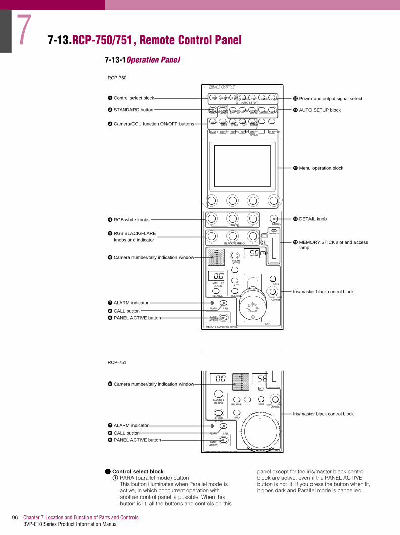
7
Chapter 7 Location and Function of Parts and ControlsBVP-E10 Series Product Information Manual
96
7-13.RCP-750/751, Remote Control Panel
7-13-1Operation Panel
aaaa Control select blockA PARA (parallel mode) button
This button illuminates when Parallel mode is active, in which concurrent operation with another control panel is possible. When this button is lit, all the buttons and controls on this
panel except for the iris/master black control block are active, even if the PANEL ACTIVE button is not lit. If you press the button when lit, it goes dark and Parallel mode is cancelled.
IRIS/MBACTIVE
AUTO
RELATIVE
COARSE
SENS
OPENCLOSERELATIVE
MASTERBLACK
EXT
IRIS
EXT
IRIS/MBACTIVE
AUTO
COARSESENS OPENCLOSERELATIVE
MASTERBLACK
IRIS
1 Control select block
2 STANDARD button
3 Camera/CCU function ON/OFF buttons
4 RGB white knobs
5 RGB BLACK/FLARE knobs and indicator
6 Camera number/tally indication window
7 ALARM indicator
8 CALL button
9 PANEL ACTIVE button
q; Power and output signal select
qa AUTO SETUP block
qs Menu operation block
qd DETAIL knob
qf MEMORY STICK slot and access lamp
Iris/master black control block
RCP-750
RCP-751
6 Camera number/tally indication window
7 ALARM indicator
8 CALL button
9 PANEL ACTIVE button
Iris/master black control block
PARA
STANDARDCHARACTER
MASTER SLAVE CAM PW
5600K
PAINT 1 PAINT 2
WHITE
ALARM CALL
REMOTE CONTROL PANEL
BLACK/FLARE a
PAINT 3 SCENE MAINTENANCE
FUNCTION
AUTOKNEE
SKINDETAIL
DTLGATE
BLACKGAMMA
TEST BARS CLOSE
LEVEL
AUTO SETUP
DETAIL
PANELACTIVE
SKIN DTLAUTO HUE
START/BREAK WHITE BLACK
ALARM CALL
REMOTE CONTROL PANEL
BLACK/FLARE a
PANELACTIVE

97Chapter 7 Location and Function of Parts and ControlsBVP-E10 Series Product Information Manual
B MASTER and SLAVE buttonsDesignate the master camera or the slave cameras to adjust the white balance of multiple cameras in Master/Slave mode. Press and light up the MASTER button to specify the connected camera to become the master. Press and light up the SLAVE button to specify the connected camera(s) to become slave. The slave cameras follow the master camera settings. If you press a button when lit, it cancels the selection.
bbbb STANDARD buttonWhen you press this button, the video camera is initialized to its standard state and the button illuminates for several seconds. If you press the button while it illuminates, the video camera reverts to the original state before Standard was selected.
cccc Camera/CCU function ON/OFF buttonsVarious functions of the video camera or the CCU/HDCU-series can be turned on and off from this panel.
5600K: 5600K -electronic colour temperature conversion functionAUTO KNEE: Auto knee function. When this button is lit (ON), the knee point is automatically adjusted according to the highlight content of the picture.SKIN DETAIL: Skin tone detail functionDTL GATE: Skin tone detail gate function. When this button is lit (ON), the adjustment range of the skin tone detail is displayed in white on the PIX (picture) monitor screen.BLACK GAMMA: Black gamma functionCHARACTER: Self-diagnostic display function. When this button is lit (ON), the contents of the self-diagnosis of the CCU/HDCU-series are displayed on the monitor connected to the CHARACTER OUTPUT connector of the CCU/HDCU-series. The contents are also mixed to the video signal to be output from the PIX1 OUTPUT connector. Each time you press this button, the status changes as follows. OFF _ ON (page 1) _ ON (page 2) . . ._ ON (page n) _ OFFThe contents of the self-diagnosis may be displayed when required even if this button is not lit. The right two buttons are for future use and do not function at present.
dddd WHITE (white balance manual adjustment) controls
Used to manually adjust the white balance. From the left, the controls are for R, G, and B signal adjustment.
eeee BLACK/FLARE (black balance/flare balance manual adjustment) controls and indicator
Used to manually adjust the black balance (when the indicator is not lit) or the flare balance (when the indicator is lit). From the left, the controls are for R, G, and B signal adjustment. Selection between black balance and flare balance is made using the Maintenance menu.
ffff Camera number/tally indication windowThe number of the camera being controlled from this panel is displayed in orange. When a red tally signal is sent to the camera, the number is displayed in black and the background of the number illuminates in red.When a green tally signal is sent to the camera, the number is displayed in black and the background of the number illuminates in green. When both the red and green tally signals are simultaneously sent, the left half of the background illuminates in red and the right half illuminates in green.
gggg ALARM indicatorIlluminates when the self-diagnostic function identifies a problem in the camera or CCU system
hhhh CALL buttonPress to send a call signal to the video camera. The tally lamps on the camera and the red tally lamp on the CCU/HDCU Series light, (or go off if already lit). When the CALL button on the video camera is pressed, the CALL button on this panel illuminates and a buzzer sounds.
iiii PANEL ACTIVE buttonPress and light up the button to permit this panel to control the camera system (Panel active status). The IRIS/MB ACTIVE button also illuminates. If you press this button so that it goes dark, the panel will be locked, preventing accidental misoperation.
jjjj Power and output signal select block
A CAM PW (camera power) buttonPress and light up this button to turn the power supply to the video camera ON. (The button promptly flashes until the camera becomes ready for transmission.) When you press this button again, it starts flashing and the power supply is turned off.
B Signal output select buttonsPress and light up one of these buttons to activate the test signal generator of the video camera and send the respective signals.TEST: To send a signal to test the video circuitsBARS: To send a colour bar signalNoteThe BARS button takes priority to the TEST button. If the BARS button is lit, press the button to turn it dark before pressing the TEST button.
C CLOSE buttonPress and light the button to close the iris. To release the close mode, press the button again so that it goes dark.
kkkk AUTO SETUP block
CHARACTER
5600K AUTOKNEE
SKINDETAIL
DTLGATE
BLACKGAMMA
CAM PW TEST BARS CLOSE
1 2 3
LEVEL
AUTO SETUP
SKIN DTLAUTO HUE
START/BREAK WHITE BLACK
1 2 43

7
Chapter 7 Location and Function of Parts and ControlsBVP-E10 Series Product Information Manual
98
A Auto adjustment item select buttonsPress and light up these buttons to select the items to be automatically adjusted.SKIN DTL AUTO HUE: Skin tone detail
automatic hue.LEVEL: Gamma balance, knee point, master
black level, etc.B START/BREAK button
Press to start automatic adjustment of the selected items. The button lights during adjustment and goes dark when adjustment is completed. If you press the button when lit, the automatic adjustment is canceled and the button flashes. To stop the flashing, press the button again.
C WHITE (white balance) buttonPress to automatically adjust the white balance. The button lights during adjustment and goes dark when adjustment is completed. If you press
this button when lit or the START/BREAK button, the automatic adjustment is canceled and the button flashes. To stop the flashing, press the button again.
D BLACK (black balance) buttonPress to automatically adjust the black balance and black set. The button lights during adjustment and goes dark when adjustment is completed. If you press this button when lit or the START/BREAK button, the automatic adjustment is canceled and the button flashes. To stop the flashing, press the button again.NoteIf an error occurs during adjustment, the pressed button flashes.
llll Menu operation block
A MODE (mode select) buttonsSelect the menu mode. If you press and light one of these buttons, the menu for the selected mode appears on the LCD.PAINT 1/2/3: Each selects the Paint menu to
adjust various paint items, such as white, black, and flare.
SCENE: Selects the File operation menu to register and retrieve scene files.
MAINTENANCE: Selects the Maintenance menu to set the H and SC phases of CCU/HDCU and operational conditions of this control panel.
FUNCTION: Selects the Function menu to control various camera and CCU/HDCU functions. When none of the buttons are lit, the status display is obtained.
B LCD/touch panelNormally displays the statuses When you press a MODE button, the corresponding menu is displayed to permit you to adjust the displayed items.
C Control knobs (rotary encoders)Adjust the selected items on the touch panel.
D DETAIL knobUsed to adjust the detail level. You may select HD detail or SD detail using the Maintenance menu.
E MEMORY STICK media card slot and access lampInsert a Memory Stick media card to store setting data, such as reference files and scene files of the video camera orCCU/HDCU.The access lamp shows the status of the Memory Stick media card.Off: No Memory Stick media card is inserted.Lit in green: There is a Memory Stick media
card in the slot. In this condition, you can safely eject the Memory Stick media card.
Lit in red: Data are being read/written. If you eject the Memory Stick media card in this condition, the data are not guaranteed. All the data may be lost.
PAINT 1 PAINT 2 PAINT 3 SCENE MAINTENANCE
FUNCTION
1
2
3

99Chapter 7 Location and Function of Parts and ControlsBVP-E10 Series Product Information Manual
7-13-2Iris/master black control block (RCP-750)
aaaa MASTER BLACK displayDisplays the current master black setting in the range from -99 to +99.
bbbb MASTER BLACK RELATIVE buttonWhen the IRIS/MB ACTIVE button is lit, the master black adjustment mode can be selected with this button.Press and light up the button for Relative mode, or press and turn it off for Absolute mode. Use of Relative mode ensures that the Master Black level of the camera does not jump when changing between the RCP and another control panel, such as an MSU. When the IRIS/MB ACTIVE button is not lit, Relative mode is automatically selected and this button is not operative.
cccc IRIS/MB ACTIVE (iris/master black active) button
Press and light up this button to enable the iris/master black control block of the panel. When the PANEL ACTIVE button is pressed, this function is automatically selected also . If you press this button so that it goes dark, the panel will be locked, preventing accidental misoperation.
dddd AUTO buttonPress and light the button to automatically adjust the iris according to the brightness of the subject. When this button is lit, the reference value for automatic iris adjustment can be set in a range of ±2f stops with the iris control. If you press the button when lit, it goes dark and manual iris adjustment is enabled.
eeee f-number displayDisplays the f-number of the current iris setting. When the iris is closed, "CL" is displayed.
ffff EXT (lens extender) indicatorIlluminates when the lens extender is used.
gggg SENS (sensitivity) control knobUsed for manual iris adjustment in Absolute mode. This control is not operative when Relative mode is selected.
hhhh COARSE control knobUsed for manual iris adjustment.
iiii Master black control ringTurn to manually adjust the master black level.
jjjj IRIS control leverWhen the AUTO button is not lit, you can adjust the iris manually by moving the lever. When the AUTO button is lit, the reference value for automatic iris adjustment can be set in a range of s ±2f with this lever. Pressing the IRIS control lever activates the RCP preview function.See the following table "Iris adjustment functions."
kkkk IRIS RELATIVE (iris relative) buttonWhen the IRIS/MB ACTIVE button is lit, the iris adjustment mode can be selected with this button. Press and light up the button for Relative mode or press so that it goes dark for Absolute mode. Use of Relative mode ensures that the lens Iris setting does not jump when changing between the RCP and another control panel, such as an MSU. When the IRIS/MB ACTIVE button is not lit, Relative mode is automatically selected and this button is not operative.
IRIS/MBACTIVE
AUTO
RELATIVECOARSE
SENS
OPENCLOSERELATIVE
MASTERBLACK
EXT
IRIS
1 MASTER BLACK display
2 MASTER BLACK RELATIVE button
3 IRIS/MB ACTIVE button
4 AUTO button
5 f-number display
6 EXT indicator
7 SENS control knob
8 COARSE control knob
9 Master black control ring
q; IRIS control lever
qa IRIS RELATIVE button

7
Chapter 7 Location and Function of Parts and ControlsBVP-E10 Series Product Information Manual
100
7-13-3Iris/master black control block (RCP-751)
aaaa MASTER BLACK displayDisplays the current master black setting in the range from -99 to +99.
bbbb MASTER BLACK controlManually adjust the master black level. The setting is displayed in the MASTER BLACK display.
cccc IRIS/MB ACTIVE (iris/master black active) button
Press and light up this button to enable the iris/master black control block of the panel. When the PANEL ACTIVE button is pressed, this button also illuminates. If you press this button so that it goes dark, the panel will be locked, preventing accidental misoperation.
dddd IRIS RELATIVE (iris relative) buttonWhen the IRIS/MB ACTIVE button is lit, the iris adjustment mode can be selected with this button. Press and light up the button for Relative mode or press so that it goes dark for Absolute mode. Use of Relative mode ensures that the lens Iris setting does not jump when changing between the RCP and another control panel, such as an MSU. When the IRIS/MB ACTIVE button is not lit, Relative mode is automatically selected and this button is not operative.
eeee f-number displayDisplays the f number of the current iris setting. When the iris is closed, "CL" is displayed.
ffff EXT (lens extender) indicatorIlluminates when the lens extender is used.
gggg SENS (sensitivity) control knobUsed for manual iris adjustment in Absolute mode. This control is not operative when Relative mode is selected.
hhhh COARSE control knobUsed for manual iris adjustment.
iiii IRIS controlWhen the AUTO button is not lit, you can adjust the iris manually by turning the control. When the AUTO button is lit, the reference value for automatic iris adjustment can be set in a range of ±1f with this control.
jjjj Iris markerThe white line on the marker provides a click position for the IRIS control. Turn the marker to set the line to the most frequently used iris position, to allow this known setting to be quickly repeated. The marker rotates infinitely in either direction. When no click position is
Iris adjustment functions
Relative mode (RELATIVE button lit) Absolute mode (RELATIVE button not lit)
IRIS lever Adjusts the iris with relative values within 1/4 of the total range from OPEN to CLOSED.
Adjusts the iris within the variable range set by the SENS and COARSE
COARSE control Adjusts the total range from OPEN to CLOSED in relative values.
Sets the lower limit for CLOSED.
SENS control Does not function. Sets the upper limit for OPEN accord-ing to CLOSED value set by the COARSE control.
EXT
IRIS/MBACTIVE
AUTO
COARSESENS OPENCLOSERELATIVE
MASTERBLACK
IRIS
qa AUTO button
1 MASTER BLACK display
2 MASTER BLACK control
3 IRIS/MB ACTIVE button
4 IRIS RELATIVE button
5 f-number display
6 EXT indicator
7 SENS control knob
8 COARSE control knob
9 IRIS control
q; Iris gauge

101Chapter 7 Location and Function of Parts and ControlsBVP-E10 Series Product Information Manual
required, set the line outside the rotation range of the IRIS control.
kkkk AUTO buttonPress and light the button to automatically adjust the iris according to the amount of input light. When this button is lit, the reference value for automatic iris adjustment can be set in a range of ±2f with the iris control. If you press the button when lit, it goes dark and manual iris adjustment is enabled.
7-13-4Connector Panel
aaaa CCU/CNU REMOTE (camera control unit/camera command network unit remote) connector (8-pin)
Connect to the RCP/CNU connector of a camera control unit or the RCP connector of a camera command network unit.
bbbb AUX REMOTE (auxiliary remote) connector (8-pin)
Connect to the RCP-700/701.
cccc EXT I/O (external input/output) connector (9-pin)Provides preview function to control an external switcher for camera monitoring
CautionWhen installing this panel, provide a gap of 7 cm (3 inches) or more behind the connector panel to prevent damage to cables.
1 CCU/CNU REMOTE connector
2 AUX REMOTE connector
3 EXT I/O connector
REMOTECCU/CNU AUX EXT I/O

7
Chapter 7 Location and Function of Parts and ControlsBVP-E10 Series Product Information Manual
102
7-14.RM-B150, Hand-held Remote Control Unite
7-14-1Operation Panel
aaaa Shutter control block
A SHUTTER button (amber illumination)Press and illuminate the button to set the camera to Shutter mode. The current shutter speed is shown on the display of the menu operation block for a few seconds. In Shutter mode, the shutter speed is adjusted with the menu select knob (rotary encoder).
B ECS (Extended Clear Scan) button (amber illumination)Press and illuminate the button to set the camera to ECS mode. The current ECS frequency is shown on the display of the menu operation block for a few seconds. In ECS mode, the ECS frequency is adjusted with the menu select knob (rotary encoder).
C S-EVS (Super EVS) button (amber illumination)Press and illuminate the button to set the camera to S-EVS mode. The current S-EVS value is shown on the display of the menu operation block for a few seconds. In S-EVS mode, the S-EVS value is adjusted with the menu select knob (rotary encoder).
1 Shutter control blockSHUTTER ECS
SELECTDISPLAYON
OFFMENU CANCEL ENTER
S-EVS
REW
STOP
F FWD
VTR
GAINOUTPUTFILTER
KNEE
WHITE
MENU
M GAMMA DETAIL
PLAY REC REVIEW
START/STOP
CAMBARSTEST
LOWMID
HIGH
1 2 3 4 5 A B C D E
ND
AUTOKNEE
R B
CC
BLACK
MASTERBLACK
REMOTE CONTROL UNIT RM-B150
R B
A
B PRE
AWB
ABB
AUTO
EXT
IRIS
ACTIVE STANDARD
IRIS/MB ACTIVE
2 Filter control block
3 Paint control block
4 White balance control block
5 Black balance control block
6 ACTIVE button
7 STANDARD button
8 Iris/master black control block
9 VTR control block
q; OUTPUT selector
qa GAIN selector
qs MENU operation block
SHUTTER ECS S-EVS
1 2 3

103Chapter 7 Location and Function of Parts and ControlsBVP-E10 Series Product Information Manual
Notes:• When you change the shutter speed, ECS
frequency or S-EVS value in the corresponding mode, the menu block display shows it for a few seconds.
• When this unit is in RM Configuration Menu mode, the shutter speed, ECS frequency and S-EVS value cannot be adjusted.
bbbb Filter control block
A ND (ND filter) indicatorsThe indicator corresponding to the currently selected ND filter illuminates.
B ND (ND filter select) buttonPress and illuminate the button when it is not lit (Filter camera control mode) to enable filter selection from this unit. When this button is illuminated, the ND filter cyclically changes in the sequence of 1_2_3_4_5_1_... each time it is pressed.
C CC (colour temperature conversion filter) indicatorsThe indicator that corresponds to the currently selected CC filter is illuminated.
D CC (colour temperature conversion filter select) buttonPress and illuminate the button when it is not lit (Filter camera control mode) to enable filter selection from this unit. When this button is illuminated, the CC filter cyclically changes in the sequence of A_B_C_D_E_A_... each time it is pressed.Notes:• Once you press any of the filter select buttons,
both buttons illuminate. The illumination is switched off when filter selection is made on the camera.
• The choice of filters that can be selected depends on the camera being used. For available filters, refer to the Operation Manual of the camera.
• For a camera with four filters, you can change the function of this button to skip 5 or E and switch from 4 to1 or from D to A using the RM Configuration menu. However, when the connected camera has an automatic filter-detection facility, setting with the RM Configuration menu is not required.
cccc Paint control block
A AUTO KNEE button (amber illumination)This button is specified at the factory to turn the auto knee function on and off. Press and illuminate the button to turn the auto knee function on. However, you can use the RM Configuration menu to change the function that is turned on/off with this button
B KNEE controlThe control is specified at the factory to adjust the master knee point. However, you can use the RM Configuration menu to change the function that is adjusted with this control.
C M GAMMA (master gamma) controlThe control is specified at the factory to adjust the master gamma. However, you can use the RM Configuration menu to change the function that is adjusted with this control.
D DETAIL controlThe control is specified at the factory to adjust the detail level. However, you can use the RM Configuration menu to change the function that is adjusted with this control.NoteThe adjustment mode of the above three controls is specified at the factory as Relative mode, which can be changed to Absolute mode using the RM Configuration menu. The centre click position of each control is the reference position in Relative mode. The adjustment range in Relative mode is also selected using the menu.
dddd White balance control block
A WHITE (white balance) controlsAdjusts the R/B white balance. The adjustment mode of these controls is specified at the factory as Relative mode, which can be changed to Absolute mode using the RM Configuration menu. See 'Settings on the RM Configuration Menu'.
B A (memory A) button (amber illumination)Press and illuminate the button to obtain the white balance setting stored in memory A of the camera (Memory A mode). When this button is illuminated, adjustments made to the white balance are stored in memory A. Press the button again to release Memory A mode.
C B (memory B) button (amber illumination)Press and illuminate the button to obtain the white balance setting stored in memory B of the camera (Memory B mode). When this button is illuminated, adjustments made to the white balance are stored in memory B. Press the button again to release Memory B mode.
D AWB (auto white balance) button (red illumination)Press to start automatic adjustment of the selected items. The button is illuminated during adjustment and this is turned off when adjustment is complete. If you press the button while it is illuminated, the automatic adjustment is canceled and the button flashes. To stop it flashing, press the button again.
E PRE (preset) button (amber illumination)Press and illuminate the button to fix the white balance to 3200K (Preset mode). Press the button again to release Preset mode.NoteIn Preset mode, manual adjustment with the WHITE controls and automatic adjustment with the AWB button are both disabled. When the adjustment mode of the WHITE controls is
1 2 3 4 5 A B C D E
FILTER
ND CC
1
2
3
4
1 2 3 4
KNEE M GAMMA DETAIL
AUTOKNEE
WHITER B
1 2 3 4 5
A
B PRE
AWB

7
Chapter 7 Location and Function of Parts and ControlsBVP-E10 Series Product Information Manual
104
specified as Absolute mode, the Memory A, B and AWB buttons are disabled.
eeee Black balance control block
A BLACK (black balance) controlsThese controls are specified at the factory to adjust the R/B black balance. Using the RM Configuration menu, you can change the function of these controls to adjust the R/B flare balance. The adjustment mode of these controls is specified at the factory as Relative mode, which can also be changed to Absolute mode using the menu. See 'Settings on the RM Configuration Menu'.
B ABB (auto black balance) button (red illumination)Press to automatically adjust the black balance and black set. The button is illuminated during adjustment and this is turned off when the adjustment is completed. If you press this button when it is illuminated, the automatic adjustment is canceled, and the button flashes. To stop the flashing, press the button again.NoteWhen the adjustment mode of the BLACK controls is specified as Absolute mode, automatic black balance adjustment with the ABB button is disabled.
ffff ACTIVE button (green illumination)Press to select the control mode for the connected camera system. Each time you press the button, the control mode cyclically switches between FULL, PART, and LOCK modes.
FULL mode: All controls from this unit are enabled (panel active status). Both this button and the IRIS/MB ACTIVE indicator in the iris/master black control block are illuminated.PART mode: Controls only from the iris/master black control block are enabled (iris/master black active status). This button is not illuminated, but the IRIS/MB ACTIVE indicator stays lit.LOCK mode: All controls from this unit are disabled (lock status). Neither this button nor the IRIS/MB ACTIVE indicator in the iris/master black control are illuminated.
Using the RM Configuration menu, the function of this button can be changed to switch only between FULL and LOCK modes. The RM Configuration menu operation is possible in any mode. See 'Settings on the RM Configuration Menu'.
gggg STANDARD button (green illumination)When this button is pressed, it remains illuminated for several seconds while the camera is initialized to its standard state. If the button is pressed while illuminated, the camera reverts to the state before the button was originally pressed.
hhhh Iris/master black control block
A MASTER BLACK controlManually adjusts the master black level. The adjustment mode of this control is specified at the factory as Absolute mode, which can be changed to Relative mode using the RM Configuration menu. See 'Settings on the RM Configuration Menu'.
B EXT (lens extender) indicator (amber illumination)Illuminates when the lens extender is in use.
C AUTO button (amber illumination)Press and illuminate the button to automatically adjust the iris according to the subject brightness. If you press the button when it is illuminated, this is turned off and manual iris adjustment is enabled.
D IRIS/MB ACTIVE (iris/master black active) indicator (green illumination)Illuminated when the control mode is set as FULL or PART mode with the ACTIVE button. When this indicator is illuminated, iris/master black controls from this unit are enabled.
E IRIS controlWhen the AUTO button is not illuminated, you can adjust the iris manually by turning this control. When the AUTO button is illuminated you can fine-adjust the reference value for the automatic iris adjustment in a range of +/-2 f stops with this control. The adjustment mode of this control is specified at the factory as Absolute mode, which can also be changed to Relative mode using the RM Configuration menu. See 'Settings on the RM Configuration Menu'.
F Iris markerTurn the marker to set the white line to the most -frequently used iris position, and it can be used as the reference for the manual iris adjustment.
iiii VTR control blockControls VTR operations. (Note these functions are designed for operation with camcorders. They can only be used with the BVP-E10 series when docked with a DNV-5 recorder
BLACKR B
ABB
1 2
MASTERBLACK
AUTO
EXT
IRIS
IRIS/MB ACTIVE
1 2 3 4
5
6

105Chapter 7 Location and Function of Parts and ControlsBVP-E10 Series Product Information Manual
AmREW (rewind) button (amber illumination): Press this button to start a rewind operation. The button is illuminated.
BMF FWD (fast forward) button (amber illumination): Press this button to start a fast-forward operation. The button is illuminated.
C START/STOP button (red illumination): Press this button to start a recording operation. The button is illuminated. Pressing this button when it is illuminated stops the VTR recording.
D xSTOP button: Press to stop a rewind, fast-forward or playback operation.
E bPLAY button (amber illumination): Press this button to start a playback operation. The button is illuminated.
F3REC REVIEW (recording review) button (amber illumination): Press this button to execute a recording review operation. The button is illuminated.Notes:• When the START/STOP button is illuminated,
the other buttons in the VTR control block are deactivated. To activate the other buttons, first press the START/STOP button to cancel the Recording mode.
• Some of the VTR control functions of this unit may be disabled depending on the combination of camera and VTR. For details, ask your official Sony representative.
jjjj OUTPUT selectorSelects the output signal from the connected camera.
CAM: Picture outputBARS: Colour bar signalTEST: Test signals for a video circuit check (the signal is selected using the RM Configuration Menu). See 'Settings on the RM Configuration Menu'.
kkkk GAIN (master gain) selectorSelects the video gain from three values (LOW, MID, HIGH) according to the illumination of the subject to be shot. Normally, these three gain settings are those chosen in the camera set-up. Alternative gain settings may be defined by using the configuration menu of the RM-B150 Operation Panel. See 'Settings on the RM Configuration Menu'.
llll MENU operation block
A Menu display (8 columns)In normal operation mode, the display illuminates to show the shutter speed, ECS frequency or S-EVS value only when the shutter control block is operated. When you select the RM Configuration menu, the display shows menu items, set values, or other information depending on operations.
B RM Configuration switchSelects the RM Configuration menu. When this switch is pushed in the V direction, the 'Basic menu' is selected.When this switch is pushed in the V direction, while holding the CANCEL/ENTER switch at ENTER, the 'Detail menu' is selected. The RM Configuration menu is switched off by pushing this switch in the v direction.
C DISPLAY switchFor control of the camera's menu.ON: Shows the character display function of the
camera.OFF: Shows the character display function of
the camera.MENU: Sets the camera into the camera menu
mode.D CANCEL/ENTER switch
To register or cancel a menu item or value selection.
E Menu select knob (rotary encoder)In normal operation, the shutter speed, ECS frequency or S-EVS value can be adjusted with this knob. In the camera's menu mode the knob is used for camera menu operations. On the RM Configuration menu, turn the knob to select menu categories, subcategories, set items, set values and other information on the menu display.For operations on the RM Configuration menu, see 'Settings on the RM Configuration Menu'. For operations on the camera's menu, refer to the Operation Manual of the camera or the System Manual.
REW
STOP
F FWD
VTR
PLAY REC REVIEW
START/STOP
1 2 3
4 5 6
1 2
3 4 5
SELECTDISPLAYON
OFFMENU CANCEL ENTER
MENU

7
Chapter 7 Location and Function of Parts and ControlsBVP-E10 Series Product Information Manual
106
7-14-2Connector Panel
aaaa CAMERA connector (8-pin)Connect to the camera using the supplied remote cable.
bbbb MONITOR connector (BNC)Connect to a colour monitor to observe the signal from the camera.Settings on the RM Configuration MenuThe RM-B150 is provided with an RM Configuration Menu mode. This enables you to select and adjust the function of the buttons and controls on the panel and to check various information. At the beginning of an RM Configuration menu operation, select 'Basic menu' or 'Detail menu' and proceed with operations as desired.
OperationFor menu operations, use the menu operation block of the unit to start the menu operation
To select the Basic menuPush the RM Configuration switch in the V direction. The menu display shows 'Cbl Comp' (the first category of the Basic menu).
To select the Detail menuPush the RM Configuration switch in the V direction while holding the CANCEL/ENTER switch toward ENTER. The menu display shows 'Mode Set' (the first category of the Detail menu).NoteThe RM Diag category of the Detail menu is used to display various information, to check operations and reset the menu. For items for which the operation procedure differs, the procedure is discussed in the corresponding 'Contents' column of the following table.
To make settings on the menu
1. Turn the menu select knob until the required category appears on the display.Example: Mode Set t ... t VR Setup
2. Push the CANCEL/ENTER switch toward ENTER to register your selection made in step 1. The first subcategory of the selected category appears.Example: KneeIf there is no subcategory belonging to the selected category, the first setting (or display) item of that category appears on the display (proceed to step 5).
3. Turn the menu select knob until the desired subcategory appears on the display.Example: Knee t ... t Iris
4. Push the CANCEL/ENTER switch toward ENTER to register your selection made in step 3. (Pushing toward CANCEL reverses the operation.) The first setting item of the selected subcategory and its current setting appear.Example: Ctrl: Abs
5. Turn the menu select knob until the desired setting (or display) item appears on the display.Example: Ctrl: Abs t ... t Min : ClsFor a setting item, make your setting.
6. Push the CANCEL/ENTER switch toward ENTER to register your setting made in step 5.
7. Turn the menu select knob until the desired category appears on the display.Example: Min : Cls t ... t Min : 22
8. Push the CANCEL/ENTER switch toward ENTER to register your setting made in step 7. (Pushing toward CANCEL cancels the setting in step 7.) To continue setting items, repeat steps 5 to 8.
To end the menu operationPush the RM Configuration switch in the v direction.Notes:• If an operation has not been made in Menu mode
after one minute, the menu automatically exits.• Values set on the RM Configuration menu are stored
in memory when you exit the menu operation. Be sure to exit the operation before turning the power off.
CAMERA MONITOR
1 CAMERA connector
2 MONITOR connector
Basic Menu (An underlined item under 'Setting' indicates the factory setting.)
Category Subcategory Item Setting Contents
Cbl Comp - Len 10m, 50m, 100m Sets the cable length for the cable com-pensation circuit
Bright - LED 10 to 99 (50) Sets the brightness of the LEDs on the con-trol panel
- Disp 10 to 99 (50) Sets the brightness of the menu display
Buzzer - Lvl 10 to 99 (50) Sets the sound volume of the buzzer
- Out On, Off Turns buzzer output on and off

107Chapter 7 Location and Function of Parts and ControlsBVP-E10 Series Product Information Manual
7-15.RM-B750, Hand-held Remote Control Unite
7-15-1Operation Panel
aaaa Memory Stick slotInsert a Memory Stick media card to store setup data, such as reference files and scene files of the video camera or camera control unit.
bbbb MEMORY STICK (Memory Stick access) lampThe lamp shows the status of the Memory Stick media card.
Off: No Memory Stick is inserted.Lit green: There is a Memory Stick in the slot. In this condition, you can safely eject the Memory Stick.Lit red: Data is being read/written. If you eject the Memory Stick in this condition, the data transfer is not guaranteed. All the data may be lost.
cccc PANEL ACTIVE buttonPress to select the control mode for the connected camera system. Each time you press the button, the control mode cyclically switches among FULL, PART, and LOCK modes*.
FULL mode: All controls from this unit are enabled (panel active status). Both this button and the IRIS/MB ACTIVE indicator in the iris/master black control block light.PART mode: Controls only from the iris/master black control block are enabled (iris/master black active status). This button goes dark, but the IRIS/MB ACTIVE indicator stays lit.LOCK mode: All controls from this unit are disabled (lock status). Both this button and the IRIS/MB
ACTIVE indicator in the iris/master black control block go dark.
*Using the RM Configuration menu under the Maintenance menu, the function of this button can be changed to switch only between FULL and LOCK modes. The RM Configuration menu operation is possible in any mode.
dddd STANDARD buttonWhen you press this button, the video camera is initialized to its standard state, and the button illuminates for several seconds. If you press the button while lit, the video camera returns to the state before the button was originally pressed.
eeee Spare buttonFor future use.
ffff Test signal output select buttonsPress and light up one of these buttons to activate the test signal generator of the video camera and send the respective signals.
TEST: To send a signal to test the video circuits. You can select the kind of the test signal to be output using the RM Configuration menu under the Maintenance menu.BARS: To send a colour bar signal
Note:The BARS button takes priority to the TEST button. If the BARS button is lit, press the button to switch it off before pressing the TEST button.
6 Test signal output select buttons
7 CLOSE button
8 VTR START/STOP button
9 VTR playback control buttons
MONITOR
FUNCTIONVF DISP
MENU SELECT
MAINTENANCEVF MENU
SCENECANCEL
PAINTENTER
ALARM
PANELACTIVE
MEMORYSTICK
STANDARD TEST BARS CLOSE
AWB
AUTOIRIS
IRIS/MBACTIVE MASTER
BLACK
REMOTE CONTROL UNIT RM-B750
EXT
IRIS
WHITE
BLACK
ABB
VTRSTART/STOP
qd White balance/black balance control block
q; ALARM indicator
Rubber cap
2 MEMORY STICK lamp
3 PANEL ACTIVE button
4 STANDARD button
5 Spare button
qs Iris/master black control block
qa Menu operation block
1 Memory Stick slot

7
Chapter 7 Location and Function of Parts and ControlsBVP-E10 Series Product Information Manual
108
gggg CLOSE buttonPress and light the button to close the iris. To release the close mode, press the button again so that it goes dark.
hhhh VTR START/STOP button. (Note these functions are designed for operation with camcorders. They can only be used with the BVP-E10 series when docked with a DNV-5 recorderPress and light up this button to start a recording operation. When you press the button when lit, it goes dark, and recording stops. Using the RM Configuration menu under the Maintenance menu, you can assign the CALL button function to this button. In this case, press to send a call signal to the video camera, on which the CALL button illuminates. The tally lamps on the camera and the red tally lamp on the camera control unit light when not lit, or go dark when lit. When the CALL button on the video camera is pressed, the button on this unit illuminates and a buzzer sounds.
iiii VTR playback control buttonsControls VTR playback operations.
s (stop) buttonPress to stop a rewind, fast-forward or playback operation.j (rewind) button
Press and light this button to start a rewind operation.H(play) buttonPress and light this button to start a playback operation.J(fast forward) buttonPress and light this button to start a fast-forward operation.7(recording review) buttonPress and light this button to execute a recording review operation.
Notes:• When the VTR START/STOP button is lit, these
buttons are deactivated. To activate the buttons, first press the VTR START/STOP button to cancel Recording mode.
• A part of the VTR control functions of this unit may be disabled depending on the combination of camera and VTR. For details, ask your Sony dealer.
jjjj ALARM indicatorFlashes or illuminates red when the self-diagnostic function identifies a problem in the camera or CCU system .
kkkk Menu operation block
A RM menu select/camera menu set buttons MONITOR: When this button is unlit, you can
select the menus of this unit using the other buttons (RM Menu mode in which the functions indicated on the panel with white characters for the buttons are valid). Press and light this button to display the video signal from the connected camera on the LCD. This also permits the menus of the camera to be operated from this unit (the functions indicated on the panel with blue characters for the buttons and the leftmost control knob are valid).
FUNCTION/VF DISP (viewfinder display): With the MONITOR button unlit, the Function menu of this unit appears on the LCD when you press and light this button. With the MONITOR button lit, the character display of the camera is turned on when you press and light this button.
MAINTENANCE/VF MENU (viewfinder menu): With the MONITOR button unlit, the Maintenance menu of this unit appears on the LCD when you press and light this button. With the MONITOR button lit, the unit enters Camera Menu mode when you press and light this button. The main menu of the camera appears on the LCD.
SCENE/CANCEL: With the MONITOR button unlit, the Scene File menu of this unit appears on the LCD when you press and light this button. With the MONITOR button lit, you can cancel the setting of the camera menu item selected on the LCD by pressing this button.
PAINT/ENTER: With the MONITOR button unlit, the Paint menu of this unit appears on the LCD when you press and light this button. With the MONITOR button lit, you can register the setting of the camera menu item selected on the LCD by pressing this button. When none of the buttons are lit, the status display is obtained.
MONITOR
FUNCTIONVF DISP
MENU SELECT
MAINTENANCEVF MENU
SCENECANCEL
PAINTENTER
1 RM menu select/camera menu set buttons
2 LCD/touch panel
3Control knobs

109Chapter 7 Location and Function of Parts and ControlsBVP-E10 Series Product Information Manual
B LCD/touch panelNormally displays the statuses. When you press and light the MONITOR button, it displays the video signal from the connected camera . In RM Menu or Camera Menu mode, the selected menu is displayed to permit you to operate the menu.
C Control knobs (rotary encoders)In RM Menu mode, adjust the selected items on the touch panel. In Camera Menu mode, select and adjust the menu items using the leftmost knob.
llll Iris/master black control block
A AUTO IRIS buttonPress and light the button to automatically adjust the iris according to the subject brightness. If you press the button when lit, it goes dark, and manual iris adjustment is enabled.
B EXT (lens extender) indicatorIlluminates when the lens extender is used on the connected camera.
C IRIS controlWhen the AUTO IRIS button is not lit, you can adjust the iris manually by turning the control. When the AUTO IRIS button is lit, you can fine-adjust the reference value for automatic iris adjustment in a range of ±2f with this control. The adjustment mode of this control is specified at the factory as Absolute mode, which can also be changed to Relative mode using the RM Configuration menu under the Maintenance menu.
D IRIS/MB ACTIVE (iris/master black active) indicatorIlluminates when the control mode is set as FULL or PART mode with the PANEL ACTIVE button. When this indicator is lit, iris/master black controls from this unit are enabled.
E MASTER BLACK controlManually adjusts the master black level. The adjustment mode of this control is specified at the factory as Relative mode, which can be changed to Absolute mode using the RM Configuration menu under the Maintenance menu.
mmmm White balance/black balance control block
A AWB (auto white balance) buttonPress to automatically adjust the white balance. The button illuminates during adjustment and goes dark when adjustment is completed. If you press this button when lit, the automatic adjustment is canceled, and the button flashes. To stop the flashing, press the button again.
B ABB (auto black balance) buttonPress to automatically adjust the black balance and black set. The button illuminates during adjustment and goes dark when adjustment is completed. If you press this button when lit, the automatic adjustment is canceled, and the button flashes. To stop the flashing, press the button again.Note:When the adjustment mode of the BLACK controls is specified as Absolute mode, automatic black balance adjustment with ABB button is disabled.
C WHITE (white balance) controlsAdjust the R/B white balance. The adjustment mode of these controls is specified at the factory as Relative mode, which can be changed to Absolute mode using the RM Configuration menu under the Maintenance menu.
D BLACK (black balance) controlsAdjust the R/B black balance. The adjustment mode of these controls is specified at the factory as Relative mode, which can be changed to Absolute mode using the RM Configuration menu under the Maintenance menu.
7-15-2Connector Panel
aaaa CAMERA connector (8-pin)Connect to the camera using the supplied remote control cable.
bbbb MONITOR connector (BNC)Connect to a colour monitor to observe the signal from the camera.
AUTOIRIS
IRIS/MBACTIVE MASTER
BLACK
EXT
IRIS
1 AUTO IRIS button
2 EXT lens extender
3 IRIS control
4 IRIS/MB ACTIVE indicator
5 MASTER BLACK control
AWBWHITE
BLACK
ABB
1 AWB button
2 ABB button
3 WHITE controls
4 BLACK controls
1 CAMERA connector
2 MONITOR connector
Cover fixing screw

7
Chapter 7 Location and Function of Parts and ControlsBVP-E10 Series Product Information Manual
110
7-16.BVF-77/77CE, Electronic Viewfinder
7-16-1Appearance
NoteIn order to use the BVF-77CE viewfinder with the BVP-E10 series camera, the CA-905F or CA-905L large lens adaptor and BKP-9057 viewfinder support are required
aaaa PEAKING controlUsed to adjust the sharpness (peaking) of the picture when the PEAKING selector is set to ON, to help ensure accurate focusing of the lens. Compensation increases as the control is turned clockwise. The compensation ranges from 0 to more than 15 dB.
bbbb PEAKING selectorAllows control compensation with the PEAKING control when this selector is set to ON. When it is set to OFF, the PEAKING control does not function, and compensation is equivalent to 0 dB.
cccc Tilt knobAdjusts the tilt friction.
dddd Lift-lock release knobAllows the viewfinder to be raised from the transport position (the lower position) to the middle or top position (the angle of the viewfinder is only adjustable at these positions). Adjust the height of the viewfinder while pulling the release knob.
PEAKING
POWER
ON
R
G
R
R
G
R
OFF
ON
OFF
NORMALSCAN SIZE
CONTRAST
BRIGHT
NARROW
12 Up-tally lamp
6
5
4 Lift-lock release knob
3
2
1
POWER switch
CONTRAST control
SCAN SIZE switch
Green tally lamps
PEAKING control 7PEAKING selector
Tilt knob
Red tally lamps
8 BRIGHT control
Tilt lock lever9
1011

111Chapter 7 Location and Function of Parts and ControlsBVP-E10 Series Product Information Manual
eeee POWER switchON: The power of the viewfinder is turned on. (Normal position)OFF: The power of the viewfinder is turned off.
ffff Green tally lampsThese illuminate when the camera receives a green tally signal. The brightness of these lamps is adjustable with an internal control.
gggg Red tally lampsThese illuminate when the camera receives a red tally signal. The brightness of these lamps is adjustable with an internal control.
hhhh BRIGHT controlUsed to adjust the picture brightness. This control has no effect on the video output signal from the camera.
iiii Tilt lock leverPushing the lever forward toward the lens locks the viewfinder. Moving it back toward the camera operator allows the viewfinder to be tilted up and down. The tilt friction may be adjusted with the tilt knob (3).
jjjj CONTRAST controlAdjusts the picture contrast.
kkkk SCAN SIZE switchNORMAL: The screen size is normal.NARROW: The screen size is 80 % of normal.
llll Up-tally lampFunctions the same as the red tally lamps on the viewfinder screen. This lamp does not illuminate when the UP TALLY switch on the camera is set to OFF.• To adjust the brightness of this lamp, refer to the
manual for the camera.• One of the supplied number plates (0 through 9) can
be attached to this lamp.
7-16-2Adjusting the Angle of the Viewfinder
25
2560
60

7
Chapter 7 Location and Function of Parts and ControlsBVP-E10 Series Product Information Manual
112
7-17.BVF-55/ 55CE, Electronic Viewfinder
7-17-1Appearances
aaaa G TALLY lamp (green)Illuminates when the green tally signal is input.
bbbb R TALLY lamp (red)Illuminates when the red tally signal is input.
cccc Up-tally lamp (red)Set UP TALLY switch to ON. The lamp illuminates in the same way as the R tally lamp. The supplied number plate can be attached to this.
dddd Tilt lock leverFixes any tilting position.
eeee 12-pin connectorConnects to a video camera's VF connector, using the supplied connecting cable.Power and video/tally signals are supplied through this connector.
ffff CONTRAST knob *1)
Adjusts the contrast of the viewfinder picture.
gggg BRIGHT knob *1)
Adjusts the brightness of the viewfinder picture.
hhhh PEAKING switch and knob *1)
Setting this switch to ON and turning the knob increases the sharpness of the viewfinder image. Used to assist the focus on the video camera. The peaking control can be turned off by a control signal sent from the camera even if the PEAKING switch is set to ON.
iiii Tilt knobAdjusts the tilt friction.
jjjj UP TALLY switchWhen this switch is set to ON, the UP TALLY lamp illuminates in the same way as the R tally lamp.
1G TALLY lamp
2R TALLY lamp
4Tilt lock lever
512-pin connector
3Up-tally lamp
8PEAKING switch and knob
6CONTRAST knob
7BRIGHT knob
9Tilt knob
q;UP TALLY switch
qaUP TALLY DIMMER control

113Chapter 7 Location and Function of Parts and ControlsBVP-E10 Series Product Information Manual
kkkk UP TALLY DIMMER controlAdjusts the brightness of the UP TALLY lamp.
*1) These controls do not affect the output signal of the video camera.
7-18.BVF-20W/20WCE, Electronic Viewfinder
7-18-1Appearances
aaaa PlugConnect to the VF connector on the camera.
bbbb StopperPrevents the viewfinder from coming off the camera when it is slid from side to side.
cccc Tally indicator (rear)Illuminates up when the camera receives a tally control signal. This indicator can be covered when not in use.
dddd Diopter adjustment ringAllows for optimal adjustment of focus.
eeee Tally indicator (front)Illuminates up when the camera receives a tally control signal. Turn the TALLY switch 9 OFF when not in use. The brightness can also be adjusted with the TALLY switch 9.
ffff PEAKING controlTurning this control clockwise adjusts the picture sharpness, and makes focusing easier. This control has no effect on the output signals of the camera.
gggg CONTRAST controlAdjusts the contrast of the screen. This control has no effect on the output signals of the camera.
hhhh BRIGHT controlAdjusts the brightness of the screen. This control has no effect on the output signals of the camera.
iiii TALLY switchControls the tally indicator 5 located on the front of the viewfinder.
HIGH: The tally indicator brightness is set to high.OFF: The tally indicator is disabled.LOW: The tally indicator brightness is set to low.
PEAKING CONTRAST BRIGHT
DISPLAYON
OFF
TALLYHIGH
LOWOFF
ZEBRAON
MOMENTOFF
1Plug
2Stopper
3Tally indicator
Eyecup
4Diopter adjustment ring
5Tally indicator
6PEAKING control
7CONTRAST control
8BRIGHT control
9TALLY switch
q;ZEBRA switch
qaDISPLAY switch
Microphone holder
Viewfinder cable

7
Chapter 7 Location and Function of Parts and ControlsBVP-E10 Series Product Information Manual
114
jjjj ZEBRA (zebra pattern) switchControls the zebra pattern display on the viewfinder screen as follows:
ON: A zebra pattern appears and stays.OFF: The zebra pattern disappears.MOMENT: A zebra pattern appears and stays for about five seconds.
kkkk DISPLAY switchEnables or disables the marker indication when the indication is set to on with the camera.
7-19.CA-905K/F/L, Large Lens Adaptor
7-19-1Lens Attachment Section (Front) and Connectors
aaaa Lens lockSecures the lens by the tongue-like protrusion at the lens bottom.
bbbb Lens lock holding knobSecures the lens lock. Turn clockwise to tighten, and counterclockwise to loosen.
cccc Lens connector (36-pin)Connect to the connector on the lens.
dddd Cable clampSecures the camera cable. The diameter of the cable with a diameter of 8 to 15 mm should be used with the cable clamp.
eeee Lens mode switchSelects one of the two lens communication modes. During normal operation, set to NORMAL. During use of a serial communication lens, set to SERIAL.
ffff CCU (camera control unit) connector (triax connector: Kings type for the CA-905K, Fischer type for the CA-905F; fibre connector: LEMO type for the CA-905L)
Connects through a triax cable or fibre cable (not supplied) to the CAMERA connector on the CCU-550D/550DP/700A/700AP.
gggg Number plate holderFit the supplied number plates.
hhhh Accessory bracketAttach an optional accessory, such as a BKP-7911/ 7912 Script Holder.
iiii CA (camera adaptor) cable (triax connector: Kings type for the CA-905K, Fischer type for the CA-905F; fibre connector: LEMO type for the CA-905L)
Connect to the CCU connector on the camera adaptor.
jjjj REMOTE cable (8-pin)Connect to the REMOTE connector on the camera adaptor.
kkkk Lens connector (12-pin)Connect to the LENS connector of the camera.
1Lens lock
BKP-9057 ViewfinderSaddle(not supplied)
2Lens lock holding knob
3Lens connector
4Cable clamp
Lens mouth
5Lens mode switch
6CCU connector
7Number plate holder
8Accessory bracket
9CA cable
q;REMOTE cable
qaLens connector

115Chapter 7 Location and Function of Parts and ControlsBVP-E10 Series Product Information Manual
7-19-2Camera-mounting Section (Inner Base) and the Optional BKP-9057 Viewfinder Saddle
aaaa VF (viewfinder) connectorConnect to the camera connector on a viewfinder.
bbbb Viewfinder mountAttach the viewfinder.
cccc Viewfinder release buttonPush this button to disengage the viewfinder
dddd Pan-lock leverTurn counterclockwise to tighten the viewfinder. Turn clockwise to loosen the viewfinder.
eeee VF connecting cable (supplied with the BKP-9057) (20-pin)
Connects to the VF connector (20-pin) on the camera.
ffff Saddle lock knobLocks the saddle so it does not topple down. Turn counterclockwise to tighten the saddle, or clockwise to loosen it.
gggg Number plate holderFit the supplied number plates.
hhhh Camera mount slide leverPull this lever to slide the camera mount forward and backward.
iiii Camera mount release leverTo remove the camera from the unit, push this lever while pushing the safety lever (on the left) rightward.
jjjj Camera mountFit the camera. Slide to the front and rear.
1VF (viewfinder) connector
2Viewfinder mount
3Viewfinder release button
4Pan-lock lever
5VF connecting cable
6Saddle lock knob7Number plate holder
8Camera mount slide lever
9Camera mount release lever
q;Camera mount

7
Chapter 7 Location and Function of Parts and ControlsBVP-E10 Series Product Information Manual
116
7-19-3Rear control panel
CA-905K/905F or CA-905L (during use with the CA-950/950P only) with PinP switch sticker attached
aaaa POWER indicatorIlluminates as follows to show the power-supply status.
Green: Power is supplied to the camera.Orange: Power is supplied to the camera, however the VF PW button of the MSU-700 or RCP-700 Series unit is set to off and power is not supplied to the viewfinder.Not lit: Power is not supplied to the camera.
bbbb Video signal select buttonsSelect the video signals (R, G, and B) displayed on the viewfinder.When no button is pressed, the following signals are output:When a monochrome viewfinder is used: The Y signal is output to the viewfinder.When a colour veiwfinder is used: The R, G, and B signals are output to the viewfinder, and a colour picture appears on the viewfinder.
cccc H-POSI (horizontal position) controlAdjusts the horizontal position of the box cursor on the viewfinder screen.
dddd V-POSI (vertical position) controlAdjusts the vertical position of the box cursor on the viewfinder screen.
eeee WIDTH controlAdjusts the width of the box cursor on the viewfinder screen.
ffff HEIGHT controlAdjusts the height of the box cursor on the viewfinder screen.
gggg CURSOR STORE buttonPress to store the size and position of the box cursor by adjusting H-POSI, V-POSI, WIDTH, and HEIGHT control.NoteIf the CURSOR ON button is not lit, the data cannot be stored.
hhhh RET (return video) buttonPush this button in to display in the viewfinder the return video signal (2, 3, or 4) selected on the CA-950/ 950P/ 570/ 570P. Push again to display the video signal from the camera.
iiii RET 1 (return video 1) buttonPush this button to display the return video 1 signal on the viewfinder screen. Push again to view the video signal from the camera.
qhMENU SELECT knob
qjMENU SELECT switch
qkDISPLAY switch
whFILTER LOCAL button
wgND filter control
wfCC filter control
wdCENTRE MARKER switch
wsSAFETY ZONE switch
waMIX VF switch
w;UP TALLY switch
qlSpare switch
8RET button
9RET 1 button
q;Back tally lamp
5WIDTH control
6HEIGHT control
3H-POSI control
4V-POSI control
1POWER indicator
2Video signal select buttons
7CURSOR STORE button
qaCURSOR ON button
qsCURSOR 1, 2, and 3 buttons
qdPinP switch (when the BKP-9057 is installed)
qfVF DETAIL control
qgVF DETAIL switch
3 H-POSI
POWER
WIDTH
V-POSI
HEIGHT STORE CORSOR
ND
FILTER LOCAL
CC
VF DETAILON
OFFENTERCANCEL
21
45
CBA
DE
R G B RET RET 1
1 2 3 ON
DISPLAY MENU SELECTON
OFF
MENU
UPTALLY
SCREENSIZE
MARKERON
OFF OFF
VFSCAN16:9
ON
4:3
SAFETYZONE
ON
OFF
CENTERMARKER
ON
OFF
3 H-POSI
POWER
WIDTH
V-POSI
HEIGHT STORE CORSOR
ND
FILTER LOCAL
CC
VF DETAILON
OFFENTERCANCEL
21
45
CBA
DE
R G B RET RET 1
1 2 3 ON
DISPLAY MENU SELECTON
OFF
MENU
UPTALLY
SCREENSIZE
MARKERON
OFF OFF
VFSCAN16:9
ON
4:3
SAFETYZONE
ON
OFF
CENTERMARKER
ON
OFF
wjSCREEN SIZE MARKER switch
wkAssignable switch

117Chapter 7 Location and Function of Parts and ControlsBVP-E10 Series Product Information Manual
jjjj Back tally lampIlluminates when a red tally signal is supplied. When the CALL button on the MSU-700 or RCP-700 Series unit is pressed, this lamp, illuminates (or goes out if it is already lit). Attach the supplied number plate to show the camera number.
kkkk CURSOR ON buttonPress and light up this button to display the box cursor on the viewfinder screen. Press this button again and make the button go out, and the box cursor disappears.
llll CURSOR (cursor memory) 1, 2, and 3 buttonsPress one of these buttons with the CURSOR STORE button blinking, and the size and position of the box cursor displayed on the viewfinder screen is recalled or stored. Three different box cursor settings can be stored using these buttons. You can recall the stored size and position of the box cursor by merely pressing the corresponding button.NoteWhen the CURSOR 1, 2, or 3 button is lit, the HPOSI, V-POSI, WIDTH, and HEIGHT controls are disabled.
mmmm PinP (Picture-in-Picture) switchUsed to display a small picture on a viewfinder screen.
POSITION: The position of the subscreen moves each time you move the switch from ON to this position.ON: Enters PinP mode. When neither the RET 1 or RET button is depressed, you can monitor the camera's signal on the viewfinder screen and the last selected return video signal on the small picture. Press either the RET 1 or RET button to switch the pictures on the viewfinder screen and the small picture.OFF: The subscreen does not appear. Two other modes can also be selected.
Note"Picture in Picture" function of the 7-inch viewfinder (BVF-77/77CE, BVF-7700/7700P) does not work when the BKP-9057 (Viewfinder Saddle for 7-inch Type Viewfinder) is used.
nnnn VF DETAIL (viewfinder detail) controlAdjusts the amount of detail of the picture on the viewfinder screen when the VF DETAIL switch is set to ON. This has no effect on the output signal of the camera.Notes• The viewfinder detail control function has no effect on
a return video signal and a picture on a subscreen of Picture-in-Picture function.
• VF DETAIL control does not work in the following conditions:- The BKP-9057 is attached to this adaptor
oooo VF DETAIL (viewfinder detail adjustment) switchON: Emphasizes the contours of the image on the viewfinder screen. When the switch is set to this position, you can adjust the amount of detail using the VF DETAIL control.OFF: Disables contour emphasis.
NoteVF DETAIL switch does not work in the following conditions:- The BKP-9057 is attached to this adaptor
pppp MENU SELECT knobFor menu item selection and value setting on the viewfinder screen.
qqqq MENU SELECT switchENTER: Activates the selection made by the MENU SELECT knob.CANCEL: Cancels the selection made by the MENU SELECT knob and restores the previously selected menu item.
rrrr DISPLAY switchUsed to display the status of the switch settings, automatic adjustment items, and results on the viewfinder screen.
ON: The display function is enabled.OFF: The display function is disabled.MENU: A menu for setting the displaying items and functions appears.
ssss Spare switch
tttt UP TALLY switchEnables the lens tally lamp, and external tally lamp on the viewfinder when a red tally signal is supplied to this camera system.
ON: The tally lamps light.OFF: The tally lamps do not light.
uuuu MIX VF (mix viewfinder) switch Selects the picture in the viewfinder when the RET 1 or RET button is depressed.
ON: When the RET 1 or RET button is depressed, the mixed picture of the camera output signal and the return video signal (return video 1 or the return video 2) can be monitored on the viewfinder screen. The mixing ratio can be adjusted with the control on the internal board of the CCU-900/ 900P/ 700A/ 700AP.OFF: When the RET 1 button or RET button is pushed, only the return video 1 signal or return video 2 signal can be seen.
NotesMIX VF switch does not work when the CCU-550D/550DP is connected.
vvvv SAFETY ZONE switchON: A box cursor (safety zone) indicating 90% of the picture appears on the viewfinder screen.OFF: A safety zone does not appear on the viewfinder screen.You can change the size of the safety zone to 80% with a menu on the camera.
wwww CENTRE MARKER switchON: A white cross (centre marker) indicating the centre of the viewfinder screen appears on theviewfinder screen. You can adjust the position of the centre marker to the centre of the lens to be used. The adjusted position can be stored in a lens file.OFF: The centre marker is disabled.
xxxx CC (colour temperature conversion) filter control
Selects a filter suitable for the lighting conditions when the FILTER LOCAL button is lit.Not applicable to BVP-E10/BVP-E10P cameras
yyyy ND filter controlSelects the ND filter when the FILTER LOCAL button is lit. Not applicable to BVP-E10/BVP-E10P cameras
zzzz FILTER LOCAL (filter local control) buttonPress and light up this button to enable switching the CC and ND filters using the CC and ND filter controls. Press this button again so it goes out to return filter

7
Chapter 7 Location and Function of Parts and ControlsBVP-E10 Series Product Information Manual
118
control to the master setup unit or remote control panel. Not applicable to BVP-E10/BVP-E10P cameras
wjwjwjwjSCREEN SIZE MARKER switchEnables a marker to define the picture edges on the viewfinder screen.
ON (X): Display area is bounded by two dark margins.ON(S): Display area is bounded by two white lines.OFF: No marker is displayed.
wkwkwkwkAssignable switch No function

BVP-E10 Series Product Information Manual
18 Menu Settings

8
Chapter 8 Menu SettingsBVP-E10 Series Product Information Manual
120
8-1. MSU Security SettingsThe MSU-700A/750 has an Engineer Mode, which allows you to assign cameras to be controlled from the MSU-700A/750 and to limit the operations on the MSU-700A/750. To authorize specific persons to use this Engineer Mode, specify a security code in advance. Once the security code is set, the MSU-700A/750 will enter into the Engineer Mode only when this security code is input.
8-1-1 Specifying the Security CodeYou can set, change, or delete the security code for entering into the Engineer Mode as follows:
8-1-1-1 To set a new security code
NoteAt the factory the unit is set in a mode in which no security code is used. To use a security code, it is necessary to enable the use of a security code. See "To enable to cancel the security code"
1. Press and light the CONFIG button. The configuration menu appears on the display.
2. Press [MSU]. The MSU Configuration Menu appears.
3. Press [Security]. The Security Menu display appears.
4. Press [Engineer Mode]. The Security Menu items now appear.
5. Press [Code Change]. The numeric keys and field for entering a New Code No. are displayed.
6. Enter the desired code (1 to 8 digits) using the numeric keys, then press [OK].NoteEach digit you input will be displayed as an asterisk. The message "Retype New Code No." is then displayed.
7. Enter the same code you entered in step 5 once again, then press [OK]. The security menu is restored.
8. Press [Exit]. The specific security code is now registered. When you next press [Engineer Mode] on the security menu, the numeric keys appear and the code input is required. The MSU-700A/750 will enter the Engineer Mode, if you enter the code properly and press [OK].
MODE
MULTI
CARD
CONFIG
MAINTENANCE
FILE
PAINT
Configuration Menu
21MSUCNU
Camera CCU
Menu operation block (Example:MSU-700A)
Configuration Menu
Security
MSU Configuration
MSUAdjusting
Exit
Date /Time
MSU SWSet
Security Menu
Engineer Mode
Exit
Security Menu
Status
Engineer Mode
CodeChange
Engineer Mode
Exit
Security Menu
Status
Engineer Mode
CodeChange
Engineer Mode
ExitCode Change
OK Cancel
New CodeNo:
987
654
321
0

121Chapter 8 Menu SettingsBVP-E10 Series Product Information Manual
8-1-1-2 To change the security codeWhen the registered security code must be changed, proceed as follows.
1. Display the security menu items by following steps 1 through 3 of the above procedure for setting a new code.
2. Press [Engineer Mode]. The numeric keys and field for entering the Code No. are displayed.
3. Enter the current security code using the numeric keys, then press [OK].NoteEach digit you input will be displayed as an asterisk. Security menu items now appear.
4. Press [Code Change]. The numeric keys and field - for entering the Old Code No. are displayed.
5. Enter the old code, then press [OK]. The field for entering a New Code No. now appears.
6. Specify a New Code No. by following steps 6 through 8 of the previous procedure.
8-1-1-3 To override the security codeTo enable the Engineer Mode, a security code is required. If the operator forgets the security code, or if an urgent Engineer Mode adjustment becomes necessary when the authorized operator is absent, the security code can be canceled by the following procedure:
1. Turn on the power to the MSU-700A/750 while holding PARA, PANELACTIVE, and camera select button 1 pressed. The numeric keys appear on the display.
The unmeric keys appear on the display.
2. Press the [0] [3] [5] [9] of the numeric keys to enter "0359" in the field for entering the security code, then press [OK]. The Engineer Protection display now appears.
Engineer Mode
OK Cancel
Code No:987
654
321
0
Security Menu
Status
Engineer Mode
CodeChange
Engineer Mode
Exit
Code Change
OK Cancel
Old Code No:987
654
321
0
New Code No:
Code Change
OK Cancel
Old Code No:******** 987
654
321
0
1 2 3 4 5 6 7 8 9 10 11
PARA
PANELACTIVE
EXPAND
MULTI
TALLY
WAVEFORM MONITOR CC
0 7 0 8 0 9 1 0 1 1 1 2
0 1 0 2 0 3 0 4 0 5 0 6
PANELACTIVE
PARA EXPAND
MULTITALLY
MULTITALLY
PARA button MSU-700A
MSU-750
Camera select button 1
PANEL ACTIVE button
PARA button
PANEL ACTIVEbutton
Camera selectbutton 1

Chapter 8 Menu SettingsBVP-E10 Series Product Information Manual
8
122
3. To temporarily disable the security code, press [Code Enable] to change it from inverse video to unhighlighted display. (Once you press it again to return it to inverse video, the security code is enabled.)
4. To delete the security code, press [Code Delete]. The message "Code Delete, OK?" is displayed, press [OK] to return to the Engineer Protection display.
5. Press [Exit].Note
At the factory, the unit is set in a mode in which no security code is used.
8-1-2 Setting the Security StatusWhen in the Engineer Mode, it is possible to set restrictions which limit control capability of the MSU-700A/750 in the normal operational mode.
OperationProceed as follows:
1. Press to light the CONFIG button.
2. Press [MSU]. The MSU Configuration Menu appears.
3. Press [Security]. The Security Menu display appears.
4. Press [Engineer Mode]. The numeric keys and field for entering the Code No. are displayed.
5. Enter the security code using the numeric keys, then press [OK].NoteEach digit you input will be displayed as an asterisk. The Security Menu items now appear.
Engineer Protection
CodeEnable
Protection
Exit
Code Delete
MODE
MULTI
CARD
CONFIG
MAINTENANCE
FILE
PAINT
Configuration Menu
21MSUCNU
Camera CCU
Menu operation block(Example:MSU-700A)
Configuration Menu
Security
MSU Configuration
MSUAdjusting
Exit
Date /Time
MSU SWSet
Security Menu
Engineer Mode
Exit
Engineer Mode
OK Cancel
Code No:987
654
321
0
Security Menu
Status
Engineer Mode
CodeChange
Engineer Mode
Exit

123Chapter 8 Menu SettingsBVP-E10 Series Product Information Manual
6. Press [Status]. The display changes to the Security Status setting display.
7. Setting the status for control from the MSU-700A/750.
[Ref. Enable]: Set it to inverse video to enable access to the reference file (Factory setting: ON).[Lens Enable]: Set it to inverse video to enable access to the lens file (Factory setting: ON).[OHB Enable]: Set it to inverse video to enable acces to the OHB file (Factory setting: ON).[Full Lock]: Set it to inverse video to fully disable the MSU-700A/750 (Factory setting: OFF)[View Mode]: Set it to inverse video to disable all adjustment operations from the MSU-700A/750 (Factory setting: OFF). (Only the display and indicators will be active. This mode allows operators to view all settings, but no adjustment is posible.)[Paint Only]: Set it to inverse video to enable the paint control only (Factory setting: OFF).
8. When the status settings are completed, press[Exit]. The Security menu display in step 5 is restored.
9. Press [Engineer Mode] to exit the Engineer Mode. The statuses specified in step 7 will be applied.NoteAll operations are enabled in the Engineer Mode regardless of the above status settings.
8-1-3 MSU AssignmentWhen multiple MSU-700A/ 750 units are used in the same system, it is possible to assign specific cameras to be selected or controlled from each MSU-700A/ 750. This assignment operation is only enabled in the Engineer Mode. Turn on the CONFIG/ MSU /SECURITY/ ENGINEER Mode to activate the Engineer Mode.
OperationProceed as follows:
1. Press to light the CONFIG button on the menu control block to call the Configuration menu on the display.
2. Press [CNU]. The CNU Configuration menu appears.
NoteThe item [MSU Assign] is displayed only when the Engineer Mode is active.
3. Press [MSU Assign]. The MSU Assignment menu now appears. Simultaneously, the character display of the CNU- 700 changes to the MSU Assignment mode. Using the four arrow buttons on the MSU Assignment menu (MSU-700A/ 750), move the cursor on the character display of the CNU-700 to the point where you wish to change the assignment.
Full Lock ViewMode
PaintOnly
Security Status
Engineer Mode
Engineer Mode
Exit
LensEnable
Ref.Enable
OHBEnable
MODE
MULTI
CARD
CONFIGURATION
MAINTENANCE
FILE
PAINT
Configuration Menu
21MSUCNU
Camera CCU
Configuration Menu
(Example:MSU-700A)
CNU Configuration
RCPAssign
Exit
MSUAssign
Engineer Mode
MSU Assignment
Set
Cancel
Default
Exit
MSU Assignment menu

Chapter 8 Menu SettingsBVP-E10 Series Product Information Manual
8
124
4. Select the control mode.SUPERVISOR MSU mode: To control all the cameras connected to all the CNUs (Camera Network Unit) in the same system.LOCAL MSU mode: To control only the cameras connected to the same CNU (Camera Network Unit) as the MSU-700A/750 being operated.
Move the cursor to the required position and press [Set] on the MSU Assignment menu to switch between modes. 5. Select the camera group to be set.In LOCAL MSU mode, only the group of cameras 1 through 12 (standard) can be selected. When the SUPERVISOR mode is active, you can select each camera group in the system from the lower rows on the character display of the CNU-700.Pressing [Set] on the MSU Assignment menu with the cursor on [NEXT] calls up the setting display for the selected camera group.
5. Select the control functions for each camera.Camera Select: Selection by the corresponding camera select button on the MSU-700A/750Active/Para: Control from the MSU-700A/750 in Panel Active/Parallel mode.Each item is on (selection/control enabled) when the characters are shown in black, and off (selection/control disabled) when the characters are shown in white. Each time [Set] is pressed on the MSU Assignment menu with the cursor on the item turns it on or off.CautionBe sure to enable the camera selection for at least one camera. If selection/control is disabled for all the connected cameras, the MSU-700A/750 becomes inoperative and the MSU Assignment mode can no longer be selected. If this occurs, change the MSU assignment as described in "To restore operations of the MSU-700A/750" on the next page.
To resume the initial assignmentPress [Default] on the MSU Assignment menu.
6. When your settings are completed, press [Set] on the MSU Assignment menu with the cursor on [Ret] in the upper right of the CNU character display. (To cancel the settings, press [Cancel].) The character display of the CNU-700 returns to its previous status (MSU Assignment display). In SUPERVISOR MSU mode, perform the settings for the cameras of other groups in the same manner.
When the MSU assignment is completedPress [Exit] on the MSU Assignment menu.
8-1-3-1 To restore operations of the MSU-700A/750
If the MSU-700A/750 has become inoperative by disabling the selection/control for all the connected cameras, change the MSU assignment using the internal switches of the CNU-700 as follows:
1. Set the MODE switch to 3.The message "MSU Assignment" appears on the screen.
2. Push the SET/CANCEL switch (S6) toward SET.The same MSU Assignment display as that in step 3 on the previous page appears. Each press of the UP/DOWN switch (S5) toward DOWN moves the cursor on the display to the right, or down when it reaches the right edge of the frame. Each press of the switch toward UP moves the cursor to the left, or up when it reaches the left edge of the frame.
3. Move the cursor to the desired position, then push the SET/CANCEL switch (S6) toward SET.
4. Repeatedly push the UP/DOWN switch (S5) toward UP until the cursor reaches the SAVE position outside the frame.
5. Push the SET/CANCEL switch (S6) towards SET.The assignment set in steps 3 and 4 is written to nonvolatile memory.
6. Return the MODE switch to 0.
OFF
MSU assignment
ON
NEXT
SUPERVISER MSU mode
LOCAL MSU mode
1 - 6 CAMERA SELECT7 - 12 /ACTIVE assignment
– – – –
– – – –
– – – –
Character display of the CNU-700 (in MSU Assignment mode
1CAM
MSU assignment [LOCAL]
Camera SelectActive/Para
7CAMCamera Select
Active/Para
2CAMCamera Select
Active/Para8CAM
Camera SelectActive/Para
3CAMCamera Select
Active/Para9CAM
Camera SelectActive/Para
4CAMCamera Select
Active/Para10CAM
Camera SelectActive/Para
5CAMCamera Select
Active/Para11CAM
Camera SelectActive/Para
6CAMCamera Select
Active/Para12CAM
Camera SelectActive/Para
Ret
Example: Setting display in LOCAL MSU mode
+5 MODE CHARACTERPHASE
UP DOWN SET CANCEL
AT
SET/CANCEL switch
UP/DOWN switch
MODE switch

125Chapter 8 Menu SettingsBVP-E10 Series Product Information Manual
8-1-4 Setting the Operating Conditions of the MSU
By using the MSU Configuration menu the user can also set the built-in clock of the MSU-700A/750 and adjust various conditions of the MSU-700A/750, such as the sound volume of the warning buzzer and the brightness of the lamp and EL display.
8-1-4-1 To display the MSU Configuration menu
1. Press to light the CONFIG button.The Configuration Menu appears on the display.
2. Press [MSU].The MSU Configuration menu appears.
8-1-4-2 To set the built-in clockThe MSU-700A/750 has a built-in clock to record the date and time when reference and scene files are saved to IC memory cards. To set the clock, proceed as follows.
1. Press [Date/Time] on the MSU Configuration menu. The current setting is displayed on the Data/Time Set menu.
2. To set the date:(1) Press [Date] to set it to inverse video.
(2) Set the Year, Month, and Day with the left three control knobs.
(3) Press [Set].The set date becomes valid. To restore the previous setting, press [Cancel] instead of [Set]. Date/Time Set Exit
3. To set the time:(1) Press [Time].
(2) Set the Hour, Minute, and Second with the left three control knobs.
(3) Press [Set] in synchronization with a time signal.
The set time becomes valid. To resume the previous setting, press [Cancel] in place of [Set].
When the clock setting is completedPress [Exit] to leave this menu.
8-1-4-3 To adjust the buzzer soundA buzzer sounds on the MSU-700A/750 when it receives a call signal or when a panel control is operated. When required, you may turn on/off the buzzer or adjust the sound volume. To adjust the buzzer, proceed as follows:
1. Press [MSU Adjusting] on the MSU Configuration menu.The MSU adjustment menu appears.
MODE
MULTI
CARD
CONFIG
MAINTENANCE
FILE
PAINT
Configuration Menu
21MSUCNU
Camera CCU
Configuration Menu
(Example:MSU-700A)
Security
MSU Configuration
MSUAdjusting
Exit
Date /Time
MSU SWSet
Date/Time Set Exit
1998/7/1(WED)
11:47:00
Date Time
Date/Time Set Exit
DayMonthYear
1 71998
1999/7/1(WED)
11:47:27
Set CancelDate Time
Date/Time Set Exit
SecondMinuteHour
51 4711
1998/7/1(WED)
11:47:51
Set CancelDate Time
/Auto Iris
Clear
Buzzer LEDBright
LED DispBright
Exit
11
EL Bright

Chapter 8 Menu SettingsBVP-E10 Series Product Information Manual
8
126
Note[LED Disp Bright] is displayed with the MSU-750 only.
2. Press [Buzzer] to set it to inverse video.The lower half of the display becomes the Buzzer Volume Level adjustment display.
3. Adjust the levels with the three control knobs.Call: volume of the buzzer when a call signal is receivedTouch: volume of the buzzer when a button displayed on the EL menu display is operatedSwitch: volume of the buzzer when a button on the control panel is operated. The master volume can be adjusted with the rightmost control knob.
8-1-4-4 To turn on/off the buzzers independently
Press the corresponding button. When it is in inverse video, the buzzer is on.
[Call Buzzer]: For the buzzer sound when a call signal is received[Touch Click]: For the buzzer sound when a button displayed on the menu display is operated[Switch Click]: For the buzzer sound when a button on the panel is operated
8-1-4-5 To turn off all the buzzersPress [All Off].
When the adjustment is completedPress [Home] to return to the MSU adjustment menu, and press [Exit] to release the menu operation.
8-1-4-6 To adjust the brightness of the LEDsYou can adjust the brightness of the LEDs of the panel buttons and camera number/tally indication window. To adjust the brightness, proceed as follows.
1. Press [MSU Adjusting] on the MSU Configuration menu to display the MSU adjustment menu.
2. Press [LED Bright] to set it to inverse video. The lower half of the display becomes the LED Brightness adjustment display.
3. Adjust the brightness with the three corresponding control knobs.
Switch: Brightness of the built-in LEDs of the control buttonsTally: Brightness of the built-in LEDs of the camera number/tally indication windowOther LED: Brightness of the other LED indicator, such as those of the camera select block and the ACCESS indicatorThe master brightness can be adjusted with the rightmost control knob.
When the adjustment is completedPress [Home] to return to the MSU adjustment menu, and press [Exit] to release the menu operation.
8-1-4-7 To adjust the brightness of the EL display
You can adjust the brightness of the display of the menu control block. To adjust the brightness, proceed as follows.
1. Press [MSU Adjusting] on the MSU Configuration menu to display the MSU Adjustment menu.
2. Press [EL Bright] to set it to inverse video. The lower half of the display becomes the EL Display adjustment display.
3. Adjust the brightness with the leftmost control knob.
When the adjustment is completedPress [Home] to return to the MSU adjustment menu, and press [Exit] to leave this menu.
8-1-4-8 To adjust the brightness of the LED camera number displays (MSU-750 only)
You can adjust the brightness of the LED displays (camera number indicators) on the control panel. To adjust the brightness, proceed as follows.
1. Press [MSU Adjusting] on the MSU Configuration menu to display the MSU Adjustment menu.
2. Press [LED Disp Bright] to set it to inverse video.
Home
Buzzer Volume Level
SwitchTouch MasterCall
688530 66
All Off
SwitchClick
TouchClick
CallBuzzer
Clear
Buzzer LEDBright
LED DispBrightEL Bright
11/
LED Brightness
Other LEDTally MasterSwitch
937872 78
Clear
Buzzer LEDBright
Home
11/
EL BrightLED Disp
Bright
EL Display Brightness
Level
50
Clear
Buzzer LEDBright
Home
11/
EL BrightLED Disp
Bright

127Chapter 8 Menu SettingsBVP-E10 Series Product Information Manual
The lower half of the display becomes the LED Display Brightness adjustment display.
3. Adjust the brightness with the leftmost control knob.
When the adjustment is completedPress [Home] to return to the MSU adjustment menu, and press [Exit] to leave this menu.
8-1-4-9 To set the screen saverThe screen saver can be activated to protect the menu display when the MSU-700A/750 is not operated for a certain time. The screen saver can be turned on and off as required, and the time to activate it can be adjusted. To set the screen saver, proceed as follows.
1. Press [MSU SW Set] on the MSU Configuration menu.The MSU SW Setting display appears.
NoteThe Test SW Mode Setting area is displayed with the MSU-750 only.
2. Press [ON] to set it to inverse video to activate the screen saver.
3. When the screen saver is turned on, set the wait time (in units of minutes) until it activates by pressing f or F.
When the adjustment is completedPress [Exit] to leave this menu.
LED Display Brightness
Level
50
Clear
Buzzer LEDBright
Home
11/
EL BrightLED Disp
Bright
WaitTime
[min]
MSU SW Setting
5
Exit
ON
PIX/WFSyncro
PIX/WFAll Mode
ONON
PIX/WF ControlMode
Direct Alter-nate
Test SW Mode
3 Step 10 StepSaw
Screen Saver
Screen saver setting area

Chapter 8 Menu SettingsBVP-E10 Series Product Information Manual
8
128
8-2. Stand-alone Viewfinder Menu Tables for the BVP-E10 Series
8-2-1 Menu Items - Operation Menu
MAINTENANCE Menu
Menu Page Items: default setting Setting values
<TEST/VF OUT> 1 TEST OUT : ENC ENC/Y/R/G/B/RETURN/VFTEST CHARA : ON ON/OFFVF OUT : Y Y/R/G/B/COLORMIX VF : OFF ON/OFFCHARACTER SYNC
: VF VF/TEST
<CURSOR> 2 CURSOR : OFF ON/OFFH POSITION : 50 0 to 99W POSITION : 50 0 to 99H WIDTH : 50 0 to 99V HEIGHT : 50 0 to 99
<ZEBRA/VF DETAIL> 3 ZEBRA : ON ON/OFF: 1&2 1/2/1&2
ZEBRA1 LEVE : 75% 50 to 109%WIDTH : 10% 0 to 30%ZEBRA2 LEVEL : 100% 50 to 109%VF DTL : ON ON/OFFVF DTL GAIN : 20 0 to 99
<MARKER> 4 SAFETY ZONE : OFF: 90%: NORMAL
ON/OFF80/90NORMAL/ASPECT
ASPECTIND : OFF: .4:3.
LINE/MASK/LINE&MASK/OFF15:9 /14:9/13:9/4:3/- -(BVP-E10WS/E10WSP only)
CENTER MARKER : ON ON/OFFPOSITION : 0 -99 to 99V POSITION : 0 -99 to 99
<VF DISPLAY> 5 EX : ON 3S/ON/OFFZOOM : OFF 3S/ON/OFFDISP : LEFT LEFT/RIGT (only for the lenses with this
function)FOCUS : ON 3S/ON/OFF (only for the lenses with
this function)ND : ON 3S/ON/OFFCC : ON ON/OFF (BVP-E10WS/E10WSP only)IRIS : ON ON/OFFWHITE : ON 3S/ON/OFF5600K : ON 3S/ON/OFFGAIN : ON 3S/ON/OFFSHUTT : ON 3S/ON/OFFRETURN : ON 3S/ON/OFFATW : ON 3S/ON/OFFSCENE : ON 3S/ON/OFFMESSAG : ALL ALL/WRN/AT/OFF
< ’ !’ IND> 6ND
[IND] [NORMAL]: ON 1 - - - ON/OFF 1234
CC : ON - B - - ON/OFF ABCDWHITE : ON - A B ON/OFF PAD5600K : ON OFF ON/OFF ON/OFFGAIN : ON L - - ON/OFF LMHSHUTTER : ON OFF ON/OFF ON/OFFEXTENDER : ON OFF ON/OFF ON/OFFFORMAT : ON 59.95I(NTSC)/
50I(PAL)ON/OFF 59.94I/29.97PsF, 50I/25PsF
16:9/4:3 : ON 16:9 ON/OFF 16:9/4:3<SWITCH ASSIGN1> 7 GAIN [L] : 0dB -3/0/3/6/9/12/18/24/30/36
[M] : 9dB -3/0/3/6/9/12/18/24/30/36 [H] : 18dB -3/0/3/6/9/12/18/24/30/36WHITE [B] : B B/ATWOUTPUT [DCC] : AUTO KNEE AUTO KNEE/ADAPTIVERE.ROTATION : STD STD/RVS

129Chapter 8 Menu SettingsBVP-E10 Series Product Information Manual
8-2-2 Menu Items - Paint Menu
Paint Menu
<SWITCH ASSIGN2> 8 LENS VTR S/S : RET2 SW RET2 SW/INCOM1/INCOM2CAM VTR S/S : RET2 SW RET2 SW/INCOM1/INCOM2ASSIGNABLE : - - 5600K/ATW/CROP/- -DIMMER : - - 0 to 9/- -HANDLE SWITCH : RET-INCOM1 RET-INCOM1/RET-INCOM2/RET-
PROD/RET-ENG/ZOOM/- -ZOOM SPEED : - - 00 to 99/- -
PRESET WHITE> 9 COLOR TEMP : 3200K 2000K to 10000KFINE : 0 -99 to 99R GAIN : 0 -99 to 99B GAIN : 0 -99 to 99
<OPERATOR FILE> 10 MEMORY STICKREAD (MStCAM) Reading from a Memory StickWRITE (CAMtMS) Writing to a Memory StickPRESET Restoring the preset dataFILE ID Comment for the operation file stored
in a Memory StickCAM CODE : BVP-E10DATETIME
<LENS FILE> 11 FILE : 1 1 to 16HA14*8F2.0
Menu Page Items: default setting Setting values
Menu Page Items : default setting Setting values
<SW STATUS> P1 FLARE : ON ON/OFFGAMMA : ON ON/OFFBLK GAM : OFF ON/OFFKNEE : ON ON/OFFWHT CLIP : ON ON/OFFDETAIL : ON ON/OFFLEVEL DEP : ON ON/OFFSKIN DTL : OFF ON/OFFMATRIX : ON ON/OFF
<VIDEO LEVEL> P2 WHITE [R] [G] [B] [M]: 0 0 0 0 -99 to 99
BLACK : 0 0 0 0 -99 to 99FLARE : 0 0 0 0 -99 to 99GAMMA : 0 0 0 0 -99 to 99V MOD : 0 0 0 0 -99 to 99FLARE : ON ON/OFFV MOD : ON ON/OFFD.SHAD : ON ON/OFFTEST : OFF OFF/1/2
<GAMMA> P3LEVEL
[R] [G] [B] [M]: 0 0 0 0 -99 to 99
COARSE : 0.45 0.35 to 0.90 (0.05 unit)GAMMA TYPE : 1 or 2 1 to 7GAMMA : ON ON/OFFTEST : OFF OFF/1/2
<BLACK GAMMA> P4LEVEL
[R] [G] [B] [M]: 0 0 0 0 -99 to 99
RANGE : HIGH LOW/MID L/MID H/HIGH: OFF ON/OFF
<LOW KEY SAT> P5 LEVEL : 0 -99 to 99RANGE : HIGH LOW/MID L/MID H/HIGH
: OFF ON/OFFTEST : OFF OFF/1/2

Chapter 8 Menu SettingsBVP-E10 Series Product Information Manual
8
130
<KNEE> P6K POINT
[R] [G] [B] [M]: 0 0 0 0 -99 to 99
K SLOPE : 0 0 0 0 -99 to 99KNEE : ON ON/OFFKNEE MAX : OFF ON/OFFKNEE SAT : 0 -99 to 99AUTO KNEE : OFF OFF/AUTO/ADAPTIVEPOINT LIMIT : 0 -99 to 99SLOPE : 0 -99 to 99
<WHITE CLIP> P7W-CLIP
[R] [G] [B] [M]: 0 0 0 0: ON
-99 to 99ON/OFF
<DETAIL 1> P8 DETAIL : ON ON/OFFLEVEL : 0 -99 to 99LIMITER[M][WHT][BLK]
: 0: 0: 0
-99 to 99-99 to 99-99 to 99
CRISP : 0 -99 to 99LVL DEP : 0 ON -99 to 99 ON/OFF
<DETAIL 2> P9 H/V RATIO : 0 -99 to 99FREQ : 0 -99 to 99MIX RATIO : 0 -99 to 99FINE DTL : 0 OFF 0 to 99 ON/OFFKNEE APT : 0 OFF -99 to 99 ON/OFFDTL COMB : -50 -99 to 0
<SKIN DETAIL> P10 SKIN DTL : OFF ON/OFFSKIN GATE : OFF OFF/1/2/3
CH SW [1] [2] [3]:(ON) OFF OFF ON/OFF
HUE : AUTO AUTO AUTO Executing Auto HuePHASE : 0 0 0 0 to 359WIDTH : 30 30 30 0 to 90SAT : -89 -89 -89 -99 to 99LEVEL : 0 0 0 -99 to 99
<USER MATRIX> P11R:
[-R] [-G] [-B]: - 0 0 -99 to 99
G: : 0 - 0 -99 to 99B: : 0 0 - -99 to 99MATRIX : ON ON/OFFPRESET : - ON/OFFUSER MATRIX : - ON/OFF
<MULTI MATRIX> P12 PHASE : 0 0/23/45/68/90/113/135/158/180/203/225/248/270/293/315/338
HUE : 0 -99 to 99SAT : 0 -99 to 99ALL CLEAR Clearing the values for PHASE, HUE,
and SATMATRIX : ON ON/OFFPRESET : ON ON/OFFMULTI MATRIX : OFF ON/OFF
<CROSS COLOR> P13 SUPPRESSION : 0: OFF
0 to 99ON/OFF
<SHUTTER> P14 SHUTTER : OFF: 1/100 *a)
OFF/ON/ECS
ECS FREQ : 30.0Hz *b)EVS : OFF ON/OFF/-
Menu Page Items : default setting Setting values
*a)
NTSC: 1/100, 1/125, 1/250, 1/500, 1/1000, 1/2000
PAL: 1/60, 1/125, 1/250, 1/500, 1/1000, 1/2000
NTSC/sF: 1/60, 1/120, 1/125, 1/250, 1/500, 1/1000
PAL/sF: 1/50, 1/100, 1/125, 1/250, 1/500, 1/1000
*b)
NTSC: 60.1 to 6000 Hz
PAL: 50.2 to 6000 Hz
NTSC/sF: 30.00 to 6000 Hz
PAL/sF: 25.00 to 6000 Hz

131Chapter 8 Menu SettingsBVP-E10 Series Product Information Manual
<SCENE FILE> P15 1 2 3 4 5 STORE 1 to 5/-STANDARDMEMORY STICKREAD (MStCAM)WRITE (CAMtMS)FILE ID : CAM CODEDATE

Chapter 8 Menu SettingsBVP-E10 Series Product Information Manual
8
132
8-2-3 Menu Items - Maintenance Menu
MAINTENANCE Menu
Menu Page Items: default setting Setting values
<AUTO SETUP> M1 AUTO BLACKAUTO WHITEAUTO LEVELAUTO WHITE SHADINGAUTO BLACK SHADINGAUTO COLOR SETUPTEST : OFF OFF/1/2
<GENLOCK>(effective in thestandalone operationonly)
M2 H PHASE [COARSE] [FINE]
: 0: 0
-99 to 99-99 to 99
SC PHASE : 0 -99 to 99GENLOCK : ENABLE ENABLE/DISABLEVF VIDEO : NORMAL NORMAL/GENLOCK
<FORMAT> M3 FORMAT : 59.94I NTSC: 59.94I/29.97PsF, PAL: 50I/25PsF
PsF-SHUTTER LINK
: OFF ON/OFF
CROP : OFF (16:9) OFF (16:9)/ON (4:3) (BVP-E10WS/E10WSP only)
ZEBRA2 LEVEL : 100% 50 to 109%VF DTL : ON ON/OFFVF DTL GAIN : 20 0 to 99
<AUTO IRIS> M4 WINDOW : 1 1/2/3/4/5/6OVERRIDE : 0 -99 to 99IRIS LEVEL : 0 -99 to 99APL RATIO : 80 -99 to 99IRIS GAIN : 0 -99 to 99AUTO IRIS : ON ON/OFF
<WHITE SHADING> M5V SAW
[R] [G] [B] [M]: 0 0 0 0 -99 to 99
V PARA : 0 0 0 0 -99 to 99H SAW : 0 0 0 0 -99 to 99H PARA : 0 0 0 0 -99 to 99WHITE : 0 0 0 0 -99 to 99AUTO WHITE SHADINGWHITE SHAD MODE : RGB RGB/RB3D WHITE SHAD : ON ON/OFF
<BLACK SHADING> M6 ] [R] [G] [B] [MV SAW : 0 0 0 0 -99 to 99V PARA : 0 0 0 0 -99 to 99H SAW : 0 0 0 0 -99 to 99H PARA : 0 0 0 0 -99 to 99BLK SET : 0 0 0 0 -99 to 99BLACK : 0 0 0 0 -99 to 99MASTER GAIN : 0dB -3/0/3/6/9/12/18/24/30/36AUTO BLACK SHADING
<ENCODER> M7 CB MODE : SMPTE (NTSC)/ EBU (75%) (PAL)
SMPTE/EIA/EBU(75%)/EBU(100%)(NTSC;SMPTE/PAL;EBU(75%) stand-ard)
Q-FILTER : WIDE NORMAL/WIDE (NTSC only)<SYSTEM> M8 CCU CALL : ON ON/OFF
CHU CALL : OFF ON/OFF<DATE/TIME> M9 2000/4/30 8:32 day, time
DATE TYPE : 1 Y/Mn/D 1 to 6<OTHERS> M10 V DTL CREATION : NAM NAM/Y/G/R+G
DTL H/V MODE : H/V H/V VV BLANKING : 20H 19H/20H/21H (NTSC only)FLT WHT MEM : ON ON/OFFMENU RESUME : OPE & USER OPE&USER/ALL/OFF

133Chapter 8 Menu SettingsBVP-E10 Series Product Information Manual
8-2-4 Menu Items - File Menu
FILE Menu
8-2-5 Menu Items - Diagnosis Menu
DIAGNOSIS Menu
Menu Page Items: default setting Setting values
<OPERATOR FILE> F1 READ (MStCAM)WRITE (CAMtMS)PRESETSTORE PRESET FILEFILE IDCAM CODEDATE
<SCENE FILE> F2 1 2 3 4 5 STORESTANDARDMEMORY STICKREAD (MStCAM)WRITE (CAMtMS)FILE IDCAM CODEDATE
<REFERENCE> F3 STORE FILESTANDARDALL PRESETREAD (MStCAM)WRITE (CAMtMS)FILE IDCAM CODEDATE
<LENS FILE> F4 STORE FILENo.NAMEF NOSELECT CURRENT : 1LENS
<OHB FILE> F5 STORE FILE<FILE CLEAR> F6 PRESET OPERATOR
REFERENCE (ALL)10 SEC CLEAR : OFFLENS (CURRENT)OHB WHITE SHADEOHB BLACK SHADEOHB ND OFFSETOHB MATRIXMS FORMAT
Menu Page Items : default setting Setting values
<DIAGNOSIS> D1 ROM : - -CAMERA : - -OHB : - -VA : - -DPR : - -IF : - -AT : - -HUR : - -CCU : - -CA-570 : - -MD : - -AU : - -TR : - -


BVP-E10 Series Product Information Manual
19 Connector Pin Assignment

9
Chapter 9 Connector Pin AssignmentBVP-E10 Series Product Information Manual
136
9-1. BVP-E10 Series, Color Video Camera
9-1-1 Connector Input/Output Signals
9-1-1-1 TEST OUT
BNC 75 Ohms 1.0 V p-p
MIC IN (3P FEMALE)
(0 dBu = 0.775 Vrms)
LENS (12P FEMALE)
9-1-1-2 VF (20P FEMALE)
Note1: Specification of COMP/VBS SW SignalWhen powering on, the microcomputer of the camera identifies a viewfinder in use by detecting the voltage at pin 5.H: Color VF, L: B/W VF
. In use of B/W VFVoltage control of pin 5 is disabled during operation.Switching between the return video signal and monochromesignal for the viewfinder is done by the camera and selected signal is output at pin 12 to the viewfinder.
. In use of Color VFBy controlling the voltage at pin 5 during operation,switching between the decoded return video signal and the camera component signal is done in the viewfinder.H: Camera, L: Return video
No. Signal Specifications
1 MIC IN (G) _60 dBu High impedance balanced2 MIC IN (X)
3 MIC IN (Y)
No. Signal Specifications
1 RET VIDEO ENA-BLE IN
ENABLE: 0 VDISABLE: +5 V or OPEN
2 RET 2 ENABLE IN ENABLE: 0 VDISABLE: +5 V or OPEN
3 GND GND for UNREG
4 AUTO +5 V OUT AUTO: +5 VMANU: 0 V or OPEN
5 IRIS CONT OUT +3.4 V (F16) to+6.2 V (F2.8)
6 UNREG OUT +10.5 V to +17 V
7 IRIS POSITION IN +3.4 V (F16) to+6.2 V (F2.8)
8 AUTO/MANU OUT
AUTO IRIS: 0 VMANUAL IRIS: +5 V
9 EXTENDER ON/OFF IN
EX 2 ON: 0 VEX 0.8 ON: +1.8 VOFF: +4.8 V
10 ZOOM POSI-TION IN
WIDE: +2 VTELE: +7 V
11 SER DATA OUT H: +5VL: 0V
12 SER DATA IN H: +5VL: 0V
2 1
3
(External view)
(External view)
No. Signal Specifications
1 NC No connection
2 ABNORMAL IND OUT
L: Indicator lightsOPEN: Indicator goes out
3 16:9 MODE OUT H: NORMAL (4:3)L: WIDE (16:9)
4 NC No connection
5 COMP/VBS SW IN/OUT
*Note 1
6 CCIR/EIA OUT H: CCIR, L: EIA
7 NC No connection
8 G TALLY OUT H: Indicator lightsL: Indicator goes out
9 NC No connection
10 Y (X) OUT 1 V p-p, VF: Zi = 1 k Ohms
11 ZEBRA ON IN H: OFF, L: ON
12 VF VIDEO OUT (X) 1.0 V p-p, VF: Zi = 1 k Ohms
13 NC No Connection
14 B-Y (X) OUT 700 mV p-p, VF: Zi = 1 k Ohms,75 % color-bars
15 R-Y (X) OUT 700 mV p-p, VF: Zi = 1 k Ohms,75 % color-bars
16 BATT IND OUT H: Indicator lightsL: Indicator goes out
17 TALLY IND OUT H: Indicator lightsL: Indicator goes out
18 +9.3 V (VF) OUT REG +9.3 V
19 GND GND
20 UNREG OUT +10.5 V to +17 V
(External view)

137Chapter 9 Connector Pin AssignmentBVP-E10 Series Product Information Manual
9-1-1-3 ANALOG CA (68P FEMALE)
(0 dBu = 0.775 Vrms)
*: In connection with CCU,
**: In connection with VTR
No. Signal Specifications
1 UNREG GND GND for UNREG
2 UNREG GND GND for UNREG
3 VF UNREG GND GND for VF UNREG
4 LENS UNREG GND
GND for LENS UNREG
5 UNREG IN 10.5 V to 17 V
6 UNREG IN 10.5 V to 17 V
7 VF UNREG IN 10.5 V to 17 V
8 LENS UNREG IN 10.5 V to 17 V
9 NC No connection
10 NC No connection
11 VBS OUT (G) GND for VBS VIDEO
12 Y OUT (X) VS 1.0 V p-p, Zo = 75 Ohms
13 B-Y OUT (X) 700 mV p-p, with sample 350 mV*756 mV p-p (J) **700 mV p-p (UC) **525 mV p-p (CE) **
14 NC No connection
15 NC No connection
16 VBS GENLOCK IN (X)
1.0 V p-p ±6 dB
17 RET VIDEO IN (G) GND for RET VIDEO
18 MONITOR VIDEO OUT (X)
VS 1.0 V p-p, Zo = 75 Ohms
19 BATTERY ALARM IN
Zi = 300 Ohms *Note 2
20 NC No connection
21 AUDIO CH1 CONT OUT
0 V (0 dB) to 7 V (-50 dB or less)
22 MIC 1 OUT (Y) Zo < 600 Ohms, -60 dBu balanced
23 NC No connection
24 SKIN TONE GATE OUT
1.0 V p-p
25 TAPE REM IN *Note 4
26 VTR SYNC OUT +5.0 V p-p Negative pulse, Zo < 100 Ohms
27 RET EN OUT ENABLE; 0 V, DISABLE; +5 V or OPEN
28 PB REF IN PB; +4.5 V,CAM; 0 V or OPEN
29 H CONT IN 0 V to 5 V, Analog
30 ANALOG GND
31 DIGITAL HD OUT 3.3 V p-p for Digital
32 COM CONT IN 5 V p-p
33 IIC CLOCK OUT (CA)
5 V p-p
34 NC No connection
35 UNREG GND GND for UNREG
36 UNREG GND GND for UNREG
37 VF UNREG GND GND for VF UNREG
34
68
1
35
(External view)
38 LENS UNREG GND
GND for LENS UNREG
39 UNREG IN 10.5 V to 17 V
40 UNREG IN 10.5 V to 17 V
41 VF UNREG IN 10.5 V to 17 V
42 LENS UNREG IN 10.5 V to 17 V
43 NC No connection
44 NC No connection
45 VBS OUT (X) 1.0 V p-p ± 10 %, Zo = 75 Ohms
46 R-Y OUT (X) 700 mV p-p, with sample 350 mV*756 mV p-p (J) **700 mV p-p (UC) **525 mV p-p (CE) **
47 Y/R-Y/B-Y GND GND for Y/R-Y/B-Y
48 NC No connection
49 NC No connection
50 VBS GENLOCK IN (G)
GND for GENLOCK/H CONT IN
51 RET VIDEO IN (X) 1.0 V p-p, Zi = 1 k Ohms
52 MONITOR VIDEO OUT (G)
GND for MONITOR VIDEO
53 VTR START/STOP OUT
Zo < 10 k Ohms
54 NC No connection
55 MIC 1 OUT (G) GND for CAM MIC
56 MIC 1 OUT (X) Zo < 600 Ohms, -60 dBu balanced
57 NC No connection
58 NC No connection
59 AUDIO LEVEL IN Zi > 1 k Ohms (-15 dBu at 0 VU)
60 NC No connection
61 NC No connection
62 REC TALLY IN ON; +5 V,OFF; +2.5 V or 0 V,Zi > 20 k Ohms *Note 3
63 VTR SAVE OUT SAVE; +4.5 V, STANDBY; 0 V, Zo < 10 k Ohms
64 GND
65 NC No connection
66 COM DATA OUT 5 V p-p
67 IIC DATA IN/OUT (CA)
5 V p-p, 4700 Ohms, Pull up
68 NC No connection
No. Signal Specifications

Chapter 9 Connector Pin AssignmentBVP-E10 Series Product Information Manual
9
138
Note 2 : Specification of BATT ALARM SignalVTR has a battery voltage detection and warning signal generation circuits and it sends the signal shown below to the camera.
Note 3: Specifications of REC TALLY Signal
Note 4 :Specifications of TAPE REM Signal
9-1-1-4 DIGITAL CA (68P FEMALE)
Battery Terminal Voltage (VTR internal battery)
12.0—11.1 V dc 11.1—10.8 V dc 10.8 V dc—
2—3 V dc across 300 Z
0 V
Input Signal at Pin 19
LED on Viewfinder
1.0 ± 0.2 Hz duty 50 ± 10 %
Stays out Blinks at 1 Hz Lights up
Input Signal at Pin 62
5.0
REC TALLY signal 1.0 ± 0.2 Hz duty 50 ± 10 %
REC RESET signal10—100 msec
VTR Action
Power OFF
Power ON
When VTR changes from POWER SAVE to REC START mode, or when the servo is lost
When VTR changes from STANDBY to REC START mode, or in REC mode
At the end of tape or When VTR is put into STOP mode by itself (REC RESET signal does not appear when VTR is put into STOP mode by operating the camera)
STOP mode
+1_0.5 V dc
2.5 ± 0.5 V dc
0 ± 0.3 V dc
Tape Remaining(VTR)Input Signal at Pin 25 Remark
TAPE1 TAPE2
+5V +5V +3.4V
+5V 0V +3.1V G TALLY lamp lights at +3.1V
0V +5V +2.2V
0V 0V 0V
No. Signal Specifications
1 G (L) OUT 2.5 V p-p
2 G (2) OUT 2.5 V p-p
3 G (4) OUT 2.5 V p-p
4 G (6) OUT 2.5 V p-p
5 G (8) OUT 2.5 V p-p
6 R (L) OUT 2.5 V p-p
34
68
1
35
(External view)
7 R (2) OUT 2.5 V p-p
8 R (4) OUT 2.5 V p-p
9 R (6) OUT 2.5 V p-p
10 R (8) OUT 2.5 V p-p
11 B (L) OUT 2.5 V p-p
12 B (2) OUT 2.5 V p-p
13 B (4) OUT 2.5 V p-p
14 B (6) OUT 2.5 V p-p
15 B (8) OUT 2.5 V p-p
16 DIGITAL GND GND for DIGITAL
17 DIGITAL BLANKING OUT 3.3 V p-p
18 DIGITAL SYNC OUT 3.3 V p-p
No. Signal Specifications

139Chapter 9 Connector Pin AssignmentBVP-E10 Series Product Information Manual
9-2. CA-570/ 570P, Camera Adaptor
9-2-1 Connector Input/Output Signal
9-2-1-1 PROMTER *1/GENLOCK *2
BNC 75 Ohms 1.0 V p-p
*1: In connection with CCU
*2: In connection with VTR
9-2-1-2 TRIAXTRIAX (CA-570)Kings type Tri-LDC Connector SeriesFor details, see www.kingselectronics.com
Lemo Kings-type 4A SeriesFor details, see www.lemo.ch
TRIAX (CA-570P)Fischer type Series 1051For details, see www.fischerconnectors.com
9-2-1-3 TEST OUT
BNC 75 Ohms 1.0 V p-p
9-2-1-4 REMOTE (8P FEMALE)
19 NC No connection
20 NC No connection
21 NC No connection
22 NC No connection
23 NC No connection
24 NC No connection
25 NC No connection
26 NC No connection
27 NC No connection
28 NC No connection
29 NC No connection
30 NC No connection
31 NC No connection
32 NC No connection
33 (Reserve)
34 18 MHz OUT (G) GND for 18 MHz
35 G (1) OUT 2.5 V p-p
36 G (3) OUT 2.5 V p-p
37 G (5) OUT 2.5 V p-p
38 G (7) OUT 2.5 V p-p
39 G (M) OUT 2.5 V p-p
40 R (1) OUT 2.5 V p-p
41 R (3) OUT 2.5 V p-p
42 R (5) OUT 2.5 V p-p
43 R (7) OUT 2.5 V p-p
44 R (M) OUT 2.5 V p-p
No. Signal Specifications
45 B (1) OUT 2.5 V p-p
46 B (3) OUT 2.5 V p-p
47 B (5) OUT 2.5 V p-p
48 B (7) OUT 2.5 V p-p
49 B (M) OUT 2.5 V p-p
50 DIGITAL GND GND for DIGITAL
51 DIGITAL SAMPLE OUT 3.3 V p-p
52 DIGITAL VD OUT 3.3 V p-p
53 DIGITAL CF OUT 3.3 V p-p
54 NC No connection
55 NC No connection
56 NC No connection
57 NC No connection
58 NC No connection
59 NC No connection
60 NC No connection
61 (Reserve)
62 NC No connection
63 NC No connection
64 NC No connection
65 NC No connection
66 NC No connection
67 (Reserve)
68 18 MHz OUT (X) 3.3 V p-p
No. Signal Specifications
No. Signal Specifications
1 TX (+) BVP SERIAL DATA
2 TX (-) BVP SERIAL DATA
3 RX (+) CCU/MSU/RCP/CNU/VCSSERIAL DATA
4 RX (-) CCU/MSU/RCP/CNU/VCSSERIAL DATA
5 VIDEO (G) GND for VIDEO
6 POWER (+) OUT +12 V, 500 mA (MAX)
7 POWER (-) OUT GND for +12 V
8 VIDEO (X) OUT VBS 1.0 V p-p, Zo = 75 Ohms
CHASSIS GND CHASSIS GND
123
4 567
8
(External view)

Chapter 9 Connector Pin AssignmentBVP-E10 Series Product Information Manual
9
140
9-2-1-5 RET CONT (6P FEMALE)
9-2-1-6 INCOM 1/2 (5P FEMALE)
9-2-1-7 TRACKER (10P FEMALE)
(0 dBu = 0.775 Vrms)
9-2-1-8 AUDIO IN 1/2 (3P MALE)
(0 dBu = 0.775 Vrms)
9-2-1-9 DC IN (4P MALE)
No. Signal Specifications
1 INCOM 1MIC ON/OFF IN
Zi > 10 k OhmsON: GNDOFF: OPEN
2 INCOM 2MIC ON/OFF IN
Zi > 10 k OhmsON: GNDOFF: OPEN
3 GND
4 RET 3 ON/OFF IN Zi > 10 k OhmsON: GNDOFF: OPEN
5 RET 1 ON/OFF IN Zi > 10 k OhmsON: GNDOFF: OPEN
6 RET 2 ON/OFF IN Zi > 10 k OhmsON: GNDOFF: OPEN
No. Signal Specifications
1 INCOM MICIN (Y)
-20 dBu(CARBON_MIC)-60 dBu(DYNAMIC MIC)
2 INCOM MICIN (X)
-20 dBu(CARBON_MIC)-60 dBu(DYNAMIC MIC)
3 GND (PGM)
4 INCOMRECEIVE OUT
-20 dBu(with INCOM level controlset to mechanical center)
5 PGM 1/2 OUT -20 dBu(with PGM level controlset to mechanical center)
(External view)
5
324
1
(External view)
10 9
4
3
2
18
7
6
5
(External view)
No. Signal Specifications
1 TRACKER R OUT (X)
TRACKER RECEIVE0 dBu unbalanced
2 TRACKER T IN (G)
GND for TRACKER T
3 TRACKER R OUT (G)
GND for TRACKER R
4 PGM OUT (X) -20 dBu unbalanced
5 +12 V (T) OUT +12 V dc. 500 mA (MAX)
6 PGM OUT (G) GND for PGM
7 TRACKER T IN (X)
TRACKER TALK0 dBu / -20 dBuHigh impedance balanced
8 TRACKER T IN (Y)
TRACKER TALK0 dBu / -20 dBuHigh impedance balanced
9 UP TALLY OUT (G)
GND for UP TALLY
10 UP TALLY OUT (X)
+12 V dc 200 mA (MAX)
No. Signal Specifications
1 MIC IN (G) -60 dBu High impedancebalanced
2 MIC IN (X) -60 dBu High impedancebalanced
3 MIC IN (Y) -60 dBu High impedancebalanced
No. Signal Specifications
1 GND GND for DC (+)
2 NC No conncetion
3 NC No conncetion
4 DC (+) IN DC 10.5 V to 17 V
2 1
3
(External view)
(External view)
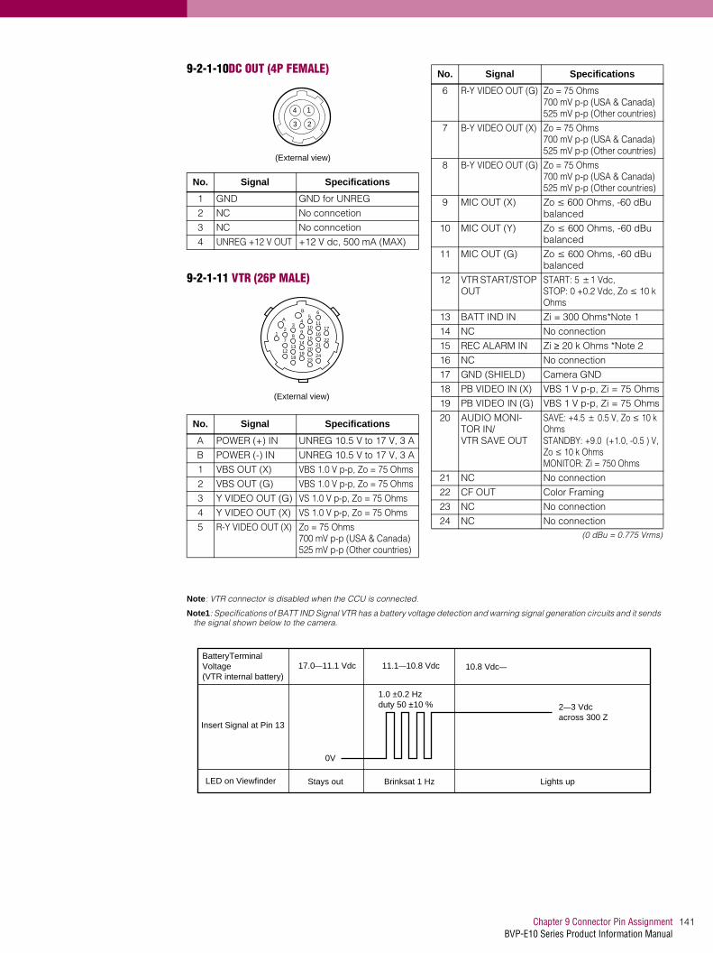
141Chapter 9 Connector Pin AssignmentBVP-E10 Series Product Information Manual
9-2-1-10DC OUT (4P FEMALE)
9-2-1-11 VTR (26P MALE)
(0 dBu = 0.775 Vrms)
Note: VTR connector is disabled when the CCU is connected.
Note1: Specifications of BATT IND Signal VTR has a battery voltage detection and warning signal generation circuits and it sends the signal shown below to the camera.
No. Signal Specifications
1 GND GND for UNREG
2 NC No conncetion
3 NC No conncetion
4 UNREG +12 V OUT +12 V dc, 500 mA (MAX)
No. Signal Specifications
A POWER (+) IN UNREG 10.5 V to 17 V, 3 A
B POWER (-) IN UNREG 10.5 V to 17 V, 3 A
1 VBS OUT (X) VBS 1.0 V p-p, Zo = 75 Ohms
2 VBS OUT (G) VBS 1.0 V p-p, Zo = 75 Ohms
3 Y VIDEO OUT (G) VS 1.0 V p-p, Zo = 75 Ohms
4 Y VIDEO OUT (X) VS 1.0 V p-p, Zo = 75 Ohms
5 R-Y VIDEO OUT (X) Zo = 75 Ohms700 mV p-p (USA & Canada)525 mV p-p (Other countries)
(External view)
1
23
4
(External view)
B
A5
6
34
12 10
11
89
7 1516
1314
12 2021
1819
22
2324
17
6 R-Y VIDEO OUT (G) Zo = 75 Ohms700 mV p-p (USA & Canada)525 mV p-p (Other countries)
7 B-Y VIDEO OUT (X) Zo = 75 Ohms700 mV p-p (USA & Canada)525 mV p-p (Other countries)
8 B-Y VIDEO OUT (G) Zo = 75 Ohms700 mV p-p (USA & Canada)525 mV p-p (Other countries)
9 MIC OUT (X) Zo ≤ 600 Ohms, -60 dBu balanced
10 MIC OUT (Y) Zo ≤ 600 Ohms, -60 dBu balanced
11 MIC OUT (G) Zo ≤ 600 Ohms, -60 dBu balanced
12 VTR START/STOP OUT
START: 5 ±1 Vdc,STOP: 0 +0.2 Vdc, Zo ≤ 10 k Ohms
13 BATT IND IN Zi = 300 Ohms*Note 1
14 NC No connection
15 REC ALARM IN Zi ≥ 20 k Ohms *Note 2
16 NC No connection
17 GND (SHIELD) Camera GND
18 PB VIDEO IN (X) VBS 1 V p-p, Zi = 75 Ohms
19 PB VIDEO IN (G) VBS 1 V p-p, Zi = 75 Ohms
20 AUDIO MONI-TOR IN/VTR SAVE OUT
SAVE: +4.5 ± 0.5 V, Zo ≤ 10 k OhmsSTANDBY: +9.0 (+1.0, -0.5 ) V, Zo ≤ 10 k OhmsMONITOR: Zi = 750 Ohms
21 NC No connection
22 CF OUT Color Framing
23 NC No connection
24 NC No connection
No. Signal Specifications
BatteryTerminalVoltage(VTR internal battery)
17.0—11.1 Vdc 11.1—10.8 Vdc 10.8 Vdc—
2—3 Vdc across 300 Z
0V
Insert Signal at Pin 13
LED on Viewfinder
1.0 ±0.2 Hz duty 50 ±10 %
Stays out Brinksat 1 Hz Lights up

Chapter 9 Connector Pin AssignmentBVP-E10 Series Product Information Manual
9
142
Note2: Specifications of REC ALARM Signal
9-2-1-12CAMERA (68P MALE)
Input Signal at Pin 15
5.0
REC ALARM signal 1.0 ± 0.2 Hz duty 50 ± 10 %
REC RESET signal10—100 msec
VTR Action
Power OFF
Power ON
When VTR changes from POWER SAVE to REC START mode, or when the servo is lost
When VTR changes from STANDBY to REC START mode, or in REC mode
At the end of tape or When VTR is put into STOP mode by itself (REC RESET signal does not appear when VTR is put into STOP mode by operating the camera)
STOP mode
+1_0.5 Vdc
2.5 ±0.5 Vdc
0 ±0.3 Vdc
No. Signal Specifications
1 UNREG GND GND for UNREG
2 UNREG GND GND for UNREG
3 VF UNREG GND GND for VF UNREG
4 LENS UNREG GND
GND for LENS UNREG
5 UNREG OUT 10.5 V to 17 V
6 UNREG OUT 10.5 V to 17 V
7 VF UNREG OUT 10.5 V to 17 V
8 LENS UNREG OUT
10.5 V to 17 V
9 R IN (X) 700 mV p-p 2 %, DC 0±200 mV, Zi ≥ 10 k Ohms
10 B IN (X) 700 mV p-p 2 %, DC 0±200 mV, Zi ≥ 10 k Ohms
11 VBS IN (G) GND for VBS VIDEO
12 Y IN (X) VS 1.0 V p-p, Zi = 1 k Ohms
13 B-Y IN (X) 700 m V p-p, with sample 350 mV *700 mV p-p (USA & Can-ada), ** 75 % color bars525 mV p-p (Other coun-tries), ** 75 % color bars
14 NC No connection
15 NC No connection
16 VBS GENLOCK OUT (X)
1.0 V p-p ± 6 dB, Zo = 75 Ohms
17 RET VIDEO OUT (G)
GND for RET VIDEO
18 MONITOR VIDEO IN (X)
VS 1 Vp-p, Zi = 1 k Ohms
19 BATTERY ALARM OUT
Zo = 300 Ohms
1
35
34
68
(External view)
20 NC No connection
21 AUDIO CH1 CONT IN
0 V (0 dB) to 7 V (-50 dB or less)
22 MIC IN (Y) Zi 600 Ohms, -60 dBu balanced
23 NC No connection
24 SKIN TONE GATE IN
1.0 V p-p
25 TAPE REM OUT No connection
26 VTR SYNC IN +5.0 V p-p Negative pulse, Zi ≤ 100 Ohms
27 RET EN IN ENABLE: 0 V, DISABLE: +5 V or OPEN
28 PB REF OUT PB: +4.5 V, CAM: 0 V or OPEN
29 H CONT OUT 0 V to 5 V, analog
30 ANALOG GND
31 DIGITAL HD IN 3.3 V p-p for digital
32 COM CONT OUT 5 V p-p
33 IIC CLOCK IN (CA)
5 V p-p
34 IIC CLOCK IN (ST)
5 V p-p
35 UNREG GND GND for UNREG
36 UNREG GND GND for UNREG
37 VF UNREG GND GND for VF UNREG
38 LENS UNREG GND
GND for LENS UNREG
39 UNREG OUT 10.5 V to 17 V
40 UNREG OUT 10.5 V to 17 V
41 VF UNREG OUT 10.5 V to 17 V
42 LENS UNREG OUT
10.5 V to 17 V
43 G IN (X) 700 mV p-p ±2 %, DC 0 ±200 mV, Zi ≥ 10 k Ohms
44 R/G/B GND GND for R/G/B VIDEO
45 VBS IN (X) 1.0 V p-p ± 10 %, Zi = 75 Ohms
No. Signal Specifications

143Chapter 9 Connector Pin AssignmentBVP-E10 Series Product Information Manual
(0 dBu = 0.775 Vrms)
*: In connection with CCU
**: In connection with VTR
9-3. CA-950/ 950P, Camera Adaptor
9-3-1 onnector Input/Output Signals
9-3-1-1 PROMTER *1/GENLOCK *2
BNC 75 Ohms 1.0 V p-p
*1: In connection with CCU
*2: Standalone use
9-3-1-2 TEST OUT
BNC 75 Ohms 1.0 V p-p
9-3-1-3 SERIAL IN/SERIAL OUT
BNC Based on SMPTE259M
9-3-1-4 REMOTE (8P FEMALE)
*1 : Standalone use
*2 : In connection with CCU
9-3-1-5 RET CONT (6P FEMALE)
46 R-Y IN (X) 700 m V p-p, with sync 350 mV *700 mV p-p (USA & Can-ada), ** 75 % color bars525 mV p-p (Other coun-tries), ** 75 % color bars
47 Y/R-Y/B-Y GND GND for Y/R-Y/B-Y
48 NC No connection
49 NC No connection
50 VBS GENLOCK OUT (G)
GND for GENLOCK
51 RET VIDEO OUT (X)
1.0 V p-p, Zo = 75 Ohms
52 MONITOR VIDEO IN (G)
GND for MONITOR VIDEO
53 VTR START/STOP IN
Zi ≤ 10 k Ohms
54 NC No connection
55 MIC IN (G) GND for CAM MIC
56 MIC IN (X) Zi ≥ 600 Ohms, -60 dBu balanced
57 NC No connection
No. Signal Specifications
58 NC No connection
59 AUDIO LEVEL OUT
No connection
60 NC No connection
61 V RESET OUT/CF IN
V Reset: 0 V to +5 V,CF: 0 V to -5 V
62 REC TALLY OUT ON: +5 V, OFF: +2.5 V or 0 V, Zo ≥ 20 k Ohms
63 VTR SAVE IN SAVE: +4.5 V, STANDBY: 0 V, Zi ≤ 10 k Ohms
64 GND
65 CA (CONT/DATA) Serial data for camera control
66 COM DATA IN 5 V p-p
67 IIC DATA IN/OUT (CA)
5 V p-p, 4700 Ohms, Pull up
68 IIC DATA IN/OUT (ST)
5 V p-p, 4700 Ohms, Pull up
No. Signal Specifications
No. Signal Specifications
1 TX (+) BVP SERIAL DATA
2 TX (-) BVP SERIAL DATA
3 RX (+) RM SERIAL DATA *1,CA-905L IIC DATA *2
4 RX (-) RM SERIAL DATA *1,CA-905L IIC DATA *2
5 VIDEO (G) GND for VIDEO
6 POWER (+) OUT 10.5 V to 17 V,500 mA (MAX)
7 POWER (-) OUT GND for +12 V
123
4 567
8
(External view)
8 VIDEO (X) OUT VBS 1.0 V p-p, Zo = 75 Ohms
CHASSIS GND CHASSIS GND
No. Signal Specifications
1 INCOM 1MIC ON/OFF IN
Zi > 10 k OhmsON: GNDOFF: OPEN
2 INCOM 2MIC ON/OFF IN
Zi > 10 k OhmsON: GNDOFF: OPEN
3 GND
4 RET 3 ON/OFF IN Zi > 10 k OhmsON: GNDOFF: OPEN
5 RET 1 ON/OFF IN Zi > 10 k OhmsON: GNDOFF: OPEN
6 RET 2 ON/OFF IN Zi > 10 k OhmsON: GNDOFF: OPEN
No. Signal Specifications
(External view)

Chapter 9 Connector Pin AssignmentBVP-E10 Series Product Information Manual
9
144
9-3-1-6 INCOM 1/2 (5P FEMALE)
9-3-1-7 AUDIO IN 1/2 (3P FEMALE)
(0 dBu = 0.775 Vrms)
9-3-1-8 DC IN (4P MALE)
9-3-1-9 DC OUT (4P FEMALE)
9-3-1-10CCU (MALE)
9-3-1-11TRACKER (FEMALE)
No. Signal Specifications
1 INCOM MICIN (Y)
.-20 dBu(CARBON_MIC).-60 dBu(DYNAMIC MIC)
2 INCOM MICIN (X)
.-20 dBu(CARBON_MIC).-60 dBu(DYNAMIC MIC)
3 GND (PGM)
4 INCOMRECEIVE OUT
.-20 dBu(with INCOM level controlset to mechanical center)
5 PGM 1/2 OUT .-20 dBu(with PGM level controlset to mechanical center)
No. Signal Specifications
1 AUDIO IN (G) LINE (-20 dBu)/ MIC (-60 dBu)SELECTABLEHigh impedance balanced
2 AUDIO IN (X) LINE (-20 dBu)/ MIC (-60 dBu)SELECTABLEHigh impedance balanced
3 AUDIO IN (Y) LINE (-20 dBu)/ MIC (-60 dBu)SELECTABLEHigh impedance balanced
No. Signal Specifications
1 GND GND for DC (+)
2 NC No connection
3 NC No connection
4 DC (+) IN DC 10.5 V to 17 V
5
324
1
(External view)
2 1
3
(External view)
(External view)
No. Signal Specifications
1 GND GND for UNREG
2 NC No connection
3 NC No connection
4 UNREG +12 V OUT
DC 10.5 V to 17 V,500 mA (MAX)
No. Signal Specifications
01 CA t CCU OPTICAL_OUTPUT.-8.5 dB (Typ.)
02 CCU t CA OPTICAL_INPUT.-20 dB (MIN)
1 CONTROL(CCU t CHU)
2 CONTROL(CHU t CCU)
3 POWER HOT STANBY : DC38 V
4 POWER COLD AC240 V
.- POWER GND GND for POWER
No. Signal Specifications
1 TRACKER R OUT (X)
TRACKER RECEIVE0 dBu unbalanced
2 TRACKER R OUT (G)
GND for TRACKER R
3 GND (UNREG/TALLY)
GND for UNREG/TALLY
4 R TALLY ON : GNDOFF : High impedance
5 PGM OUT (G) GND for PGM
6 UNREG .+12 V (+10.5 to +17.0 V)
7 TRACKER T IN (X)
TRACKER TALK0 dBu / -20 dBuHigh impedance balanced
1
23
4
(External view)
01
34
21
02
(External view)
5
1
2
6
11
16
3
7
12
17
4
8
13
9
14
18
20
19
15
10
(External view)

145Chapter 9 Connector Pin AssignmentBVP-E10 Series Product Information Manual
(0 dBu = 0.775 Vrms)
9-3-1-12CAMERA (68P MALE)
For Analog Interface (upper side)
8 TRACKER T IN (Y)
TRACKER TALK0 dBu / -20 dBuHigh impedance balanced
9 TRACKER T IN (G)
GND for TRACKER T
10 PGM OUT (X) -20 dBu unbalanced
11 (Spare)
12 G TALLY ON : GNDOFF : High impedance
13 NC No connection
14 RX_DATA_IN (0) TRUNK DATA IN, RS232-C
15 RX_DATA_IN (1) TRUNK DATA IN, RS232-C
16 NC No connection
17 NC No connection
18 TX_DATA_OUT (0) TRUNK DATA OUT, RS232-C
19 TX_DATA_OUT (1) TRUNK DATA OUT, RS232-C
20 GND
No. Signal Specifications
1 UNREG GND GND for UNREG
2 UNREG GND GND for UNREG
3 VF UNREG GND GND for VF UNREG
4 LENS UNREG GND
GND for LENS UNREG
5 UNREG OUT 10.5 V to 17 V
6 UNREG OUT 10.5 V to 17 V
7 VF UNREG OUT 10.5 V to 17 V
8 LENS UNREG OUT
10.5 V to 17 V
9 R IN (X) No connection
10 B IN (X) No connection
11 VBS IN (G) GND for VBS VIDEO
12 Y IN (X) No connection
13 B-Y IN (X) No connection
14 RET B-Y OUT (X) 0.7 V p-p, Zo = 75 Ohms
15 C IN (X) No connection
16 VBS GENLOCK OUT (X)
1.0 V p-p ±6 dB, Zo = 75 Ohms
17 RET VIDEO OUT (G)
GND for RET VIDEO
18 MONITOR VIDEO IN (X)
VS 1 Vp-p, Zi = 75 k Ohms
19 BATTERY ALARM OUT
Zo = 220 Ohms
20 NC No connection
21 AUDIO CH1 CONT IN
0 V (0 dB) to 7 ± 0.5V(-50 dB)
22 MIC IN (Y) Zi = 600 Ohms,-60 dBu balanced
No. Signal Specifications
1
35
34
68
(External view)
23 NC No connection
24 SKIN TONE GATE IN
No connection
25 TAPE REM OUT No connection
26 VTR SYNC IN No connection
27 RET EN IN ENABLE; 0 V,DISABLE; OPEN
28 PB REF OUT PB; +5.0 V, CAM; 0 V
29 H CONT OUT 0 V to 5 V,Max frequency at 5 V
30 ANALOG GND
31 DIGITAL HD IN 3.3 V p-p for Digital
32 COM CONT OUT 5 V p-p
33 IIC CLOCK IN (CA)
5 V p-p
34 IIC CLOCK IN (ST)
5 V p-p
35 UNREG GND GND for UNREG
36 UNREG GND GND for UNREG
37 VF UNREG GND GND for VF UNREG
38 LENS UNREG GND
GND for LENS UNREG
39 UNREG OUT 10.5 V to 17 V
40 UNREG OUT 10.5 V to 17 V
41 VF UNREG OUT 10.5 V to 17 V
42 LENS UNREG OUT
10.5 V to 17 V
43 G IN (X) No connection
44 R/G/B GND No connection
45 VBS IN (X) 1.0 V p-p ± 10 %, Zi = 75 Ohms
46 R-Y IN (X) No connection
47 Y/R-Y/B-Y GND No connection
48 RET R-Y OUT (X) 0.7 V p-p, Zo = 75 k Ohms
49 C GND No connection
50 VBS GENLOCK OUT (G)
GND for GENLOCK
51 RET VIDEO OUT (X)
1.0 V p-p, Zo = 75 Ohms
52 MONITOR VIDEO IN (G)
GND for MONITOR VIDEO
53 VTR START/STOP IN
Zi < 10 k Ohms
54 NC No connection
55 MIC IN (G) GND for CAM MIC
56 MIC IN (X) Zi > 600 Ohms,-60 dBu balanced
57 NC No connection
58 NC No connection
59 AUDIO LEVEL OUT
No connection
60 NC No connection
61 V RESET OUT/CF IN
No connection
62 REC TALLY OUT No connection
63 VTR SAVE IN No connection
64 GND
65 CA (CONT/DATA) No connection
66 COM DATA IN 5 V p-p
No. Signal Specifications

Chapter 9 Connector Pin AssignmentBVP-E10 Series Product Information Manual
9
146
(0 dBu = 0.775 Vrms)
9-3-1-13CAMERA (68P MALE)
For Digital Interface (lower side)
(0 dBu = 0.775 Vrms)
67 IIC DATA IN/OUT (CA)
5 V p-p, 4700 Ohms, Pull up
68 IIC DATA IN/OUT (ST)
No connection
No. Signal Specifications
1 G/Y (L) IN 3.3 V p-p to 2.5 V p-p
2 G/Y (2) IN 3.3 V p-p to 2.5 V p-p
3 G/Y (4) IN 3.3 V p-p to 2.5 V p-p
4 G/Y (6) IN 3.3 V p-p to 2.5 V p-p
5 G/Y (8) IN 3.3 V p-p to 2.5 V p-p
6 R/R-Y (L) IN 3.3 V p-p to 2.5 V p-p
7 R/R-Y (2) IN 3.3 V p-p to 2.5 V p-p
8 R/R-Y (4) IN 3.3 V p-p to 2.5 V p-p
9 R/R-Y (6) IN 3.3 V p-p to 2.5 V p-p
10 R/R-Y (8) IN 3.3 V p-p to 2.5 V p-p
11 R/B-Y (L) IN 3.3 V p-p to 2.5 V p-p
12 R/B-Y (2) IN 3.3 V p-p to 2.5 V p-p
13 R/B-Y (4) IN 3.3 V p-p to 2.5 V p-p
14 R/B-Y (6) IN 3.3 V p-p to 2.5 V p-p
15 R/B-Y (8) IN 3.3 V p-p to 2.5 V p-p
16 DIGITAL GND GND for DIGITAL
17 DIGITAL BLANK-ING IN
No connection
18 DIGITAL SYNC IN No connection
19 DIGIRAL GND GND for DIGITAL
20 VF CHARA IN 3.3 V p-p to 2.5 V p-p
21 L2 (L) IN 3.3 V p-p to 2.5 V p-p
22 L2 (2) IN 3.3 V p-p to 2.5 V p-p
23 L2 (4) IN 3.3 V p-p to 2.5 V p-p
24 L2 (6) IN 3.3 V p-p to 2.5 V p-p
25 L2 (8) IN 3.3 V p-p to 2.5 V p-p
26 DIGITAL GND GND for DIGITAL
27 L3 (L) IN 3.3 V p-p to 2.5 V p-p
28 L3 (2) IN 3.3 V p-p to 2.5 V p-p
29 L3 (4) IN 3.3 V p-p to 2.5 V p-p
30 L3 (6) IN 3.3 V p-p to 2.5 V p-p
31 L3 (8) IN 3.3 V p-p to 2.5 V p-p
32 NC No connection
33 27 MHz (G) GND for 27 MHz
34 18 MHz IN (G) GND for 18 MHz
35 G/Y (1) IN 3.3 V p-p to 2.5 V p-p
36 G/Y (3) IN 3.3 V p-p to 2.5 V p-p
37 G/Y (5) IN 3.3 V p-p to 2.5 V p-p
38 G/Y (7) IN 3.3 V p-p to 2.5 V p-p
39 G/Y (M) IN 3.3 V p-p to 2.5 V p-p
40 R/R-Y (1) IN 3.3 V p-p to 2.5 V p-p
41 R/R-Y (3) IN 3.3 V p-p to 2.5 V p-p
No. Signal Specifications
34
68
1
35
(External view)
42 R/R-Y (5) IN 3.3 V p-p to 2.5 V p-p
43 R/R-Y (7) IN 3.3 V p-p to 2.5 V p-p
44 R/R-Y (M) IN 3.3 V p-p to 2.5 V p-p
45 B/B-Y (1) IN 3.3 V p-p to 2.5 V p-p
46 B/B-Y (3) IN 3.3 V p-p to 2.5 V p-p
47 B/B-Y (5) IN 3.3 V p-p to 2.5 V p-p
48 B/B-Y (7) IN 3.3 V p-p to 2.5 V p-p
49 B/B-Y (M) IN 3.3 V p-p to 2.5 V p-p
50 DIGITAL GND GND for DIGITAL
51 SAMPLE IN/CONT1
3.3 V p-p to 2.5 V p-p
52 DIGITAL VD IN 3.3 V p-p to 2.5 V p-p
53 CF IN/CONT2 3.3 V p-p to 2.5 V p-p
54 DIGITAL SKIN GATE IN
3.3 V p-p to 2.5 V p-p
55 L2 (1) IN 3.3 V p-p to 2.5 V p-p
56 L2 (3) IN 3.3 V p-p to 2.5 V p-p
57 L2 (5) IN 3.3 V p-p to 2.5 V p-p
58 L2 (7) IN 3.3 V p-p to 2.5 V p-p
59 L2 (M) IN 3.3 V p-p to 2.5 V p-p
60 DIGITAL GND GND for DIGITAL
61 H REF OUT 3.3 V p-p
62 L3 (1) IN 3.3 V p-p to 2.5 V p-p
63 L3 (3) IN 3.3 V p-p to 2.5 V p-p
64 L3 (5) IN 3.3 V p-p to 2.5 V p-p
65 L3 (7) IN 3.3 V p-p to 2.5 V p-p
66 L3 (M) IN 3.3 V p-p to 2.5 V p-p
67 27 MHz IN (X) 3.3 V p-p to 2.5 V p-p
68 18 MHz IN (X) 3.3 V p-p to 2.5 V p-p
No. Signal Specifications

147Chapter 9 Connector Pin AssignmentBVP-E10 Series Product Information Manual
9-3-2 Wiring Diagrams for Cables
9-3-2-1 CCA-5 Cable
(Outer sheath color: White)
9-3-2-2 REMOTE Cable (supplied with RM-B150)
(Outer sheath color: Black)
8-pin connector (Male)(Wiring side)
8-pin connector (Male)(Wiring side)
Brown Brown
White
Red
Red
BrownWhite
White
Black
Orange
8P CONNECTOR (MALE)(WIRING SIDE)
8P CONNECTOR (MALE)(WIRING SIDE)
White
Red
BrownWhite
White
Black

Chapter 9 Connector Pin AssignmentBVP-E10 Series Product Information Manual
9
148
9-4. CCU-500D/ 500DP, Camera Control Unit
9-4-1 Connector Input/Output Signals
9-4-1-1 MIC OUTPUT CH1/CH2 (XLR 3P, MALE)
(0 dBu = 0.775 Vrms)
9-4-1-2 WF MODE (4P FEMALE)
*1) Stair Case signal
9-4-1-3 MIC REMOTE (D-Sub 15P, FEMALE)
*2:
*3
*4 To use these interface signals, modification for AT board is required.
9-4-1-4 INTERCOM/TALLY/PGM (D-Sub 25P, FEMALE)
No. Signal Specifications
1 MIC OUT (G) 0 dBu/ -20 dBu(Selectable with S201, S251/AU board)
2 MIC OUT (X)
3 MIC OUT (Y)
No. Signal Specifications
1 SEQ CONT OUT (G)
OPEN COLLECTOR+(PNP)/ -(NPN)(Selectable with S901/VA board)
2 SEQ CONT OUT (X)
OPEN COLLECTOR+(PNP)/ -(NPN)(Selectable with S601/DPR board)
3 STAIR CASE OUT (X)
*1
4 STAIR CASE OUT (G)
GND for STAIR CASE
No. Signal Specifications
1 +5.5 V OUT Max. 70 mA
2 AUX4 (*4 TALLY GND)
*4 TALLY for GND
1 2
3
(External view)
4 1
3 2
(External view)
12 V+1- 6
R G B DC 0 ±2 V
15 9
18
(External view)
3 AUX2 (*4 G TALLY OUT)
*4 Q405 (NPN) /AT boardON (GND) : Max 30 mA
4 AUX1 (*4 R TALLY OUT)
*4 Q403 (NPN) /AT boardON (GND) : Max 30 mA
5 CHU MIC1 CONT2
*2 See below
6 AMP CONT1 *2 See below
7 GAIN IN CONT0 *2 See below
8 MIC1 GAIN CONTON/OFF IN
*3 See below
9 GND (+5.5 V) GND for 5.5 V
10 AUX3 (*4 TALLY OUT)
*4 R/G TALLY OUTQ409 (NPN) /AT boardON (GND) : Max 30 mA
11 NC No connection
12 16:9/4:3 SELECT EN IN
+5.0 V (or OPEN): DIS-ENGND: EN
13 16:9/4:3 SELECT IN
+5.0 V (or OPEN): 4:3GND: 16:9
14 AUX9 *1 Refer to the following table.
15 MIC GAIN CONT2 IN
*2 See below
CONT0 CONT1 CONT2CHU MIC1 AMP
GAIN
H H H 60 dB
L H H 50 dB
H L H 40 dB
L L H 30 dB
H H L 20 dB
8-pin 15-pin MIC GAIN CONT
L L MIC1/MIC2 ON
L H MIC1 ON
H L MIC2 ON
H H INTERNAL SET
No. Signal Specifications
1 ENG (R) (X) OUT ENG SYSTEM RECEIVE0 dBu BALANCED
No. Signal Specifications
25 14
113
(External view)

149Chapter 9 Connector Pin AssignmentBVP-E10 Series Product Information Manual
(0 dBu = 0.775 Vrms)
9-4-1-5 REMOTE (8P, FEMALE)RCP/CNU
9-4-1-6 INTERCOM (5P, FEMALE) on the front panel
(0 dBu = 0.775 Vrms)
9-5. CCU-700A/ 700AP, Camera Control Unit
9-5-1 Connector Input/Output Signals
9-5-1-1 MIC OUTPUT CH1/CH2 (3P, MALE)
2 ENG (R) (Y) OUT ENG SYSTEM RECEIVE0 dBu BALANCED
3 GND GND for ENG
4 ENG (T) (X) IN ENG SYSTEM TALK
5 ENG (T) (Y) IN 0 dBu BALANCED
6 PGM (X) IN -20 dBu/0 dBu(Selectable with S451/AU board)
7 PGM (Y) IN -20 dBu/0 dBu(Selectable with S451/AU board)
8 PGM (G) IN -20 dBu/0 dBu(Selectable with S451/AU board)
9 GND GND for AUX
10 AUX8
11 R TALLY (X) IN ON: 24 V dc, TTL (H), SHORTOFF: 0 V dc, TTL (L), OPEN
12 R TALLY (Y) IN ON: 24 V dc, TTL (H), SHORTOFF: 0 V dc, TTL (L), OPEN
13 GND CHASSIS GND
No. Signal Specifications
14 PROD (R) (X) OUT PROD SYSTEMRECEIVE 0 dBu BAL-ANCED
15 PROD (R) (Y) OUT
PROD SYSTEMRECEIVE 0 dBu BAL-ANCED
16 PROD (G) GND for PROD
17 PROD (T) (X) IN PROD SYSTEM TALK0 dBu BALANCED
18 PROD (T) (Y) IN PROD SYSTEM TALK0 dBu BALANCED
19 NC No connection
20 NC No connection
21 NC No connection
22 AUX7
23 AUX6
24 G TALLY (X) IN ON: 24 V dc, TTL (H), SHORTOFF: 0 V dc, TTL (L), OPEN
25 G TALLY (Y) IN ON: 24 V dc, TTL (H), SHORTOFF: 0 V dc, TTL (L), OPEN
No. Signal Specifications
No. Signal Specifications
1 TX (+) CCU SERIAL DATA
2 TX (-)
3 RX (+) RCP/CNU/BVP/MSU/VCS
4 RX (-) SERIAL DATA
5 TX GND GND for TX
6 POWER (+) OUT RCP POWER, +30 V
7 POWER (-) OUT GND for POWER
8 SPARE
CHASSIS GND CHASSIS GND
123
4 567
8
(External view)
No. Signal Specifications
1 INCOM (T) IN (Y) -20_dBu_(CARBON_MIC)-60 dBu (DYNAMIC MIC)
2 INCOM (T) IN (X) -20_dBu_(CARBON_MIC)-60 dBu (DYNAMIC MIC)
3 INCOM (T) IN (G) GND for INCOM
4 INCOM (R) OUT (X) Max. 12 dBu
5 PGM OUT (X) Max. 12 dBu
(External view)
2 1
3
(External view)
No. Signal Specifications
1 MIC OUT (G) 0 dBu/ -20 dBu(Selectable with S201, S301/AT board)
2 MIC OUT (X)
3 MIC OUT (Y)

Chapter 9 Connector Pin AssignmentBVP-E10 Series Product Information Manual
9
150
9-5-1-2 RTS IN/OUT RTS IN RTS OUT (3P, FEMALE) (3P, MALE)
9-5-1-3 MIC REMOTE (15P, FEMALE)
*1) CHU MIC 1/2 AMP GAIN
9-5-1-4 INTERCOM REMOTE (25P, FEMALE)
*2) To use these interface signals, modification for AT board is required.
No. Signal Specifications
1 RTS (COMMON) 2.0 Vp-p 200 Ohms
2 RTS (ENG) D
3 RTS (PROD) GND for STAIR CASE
No. Signal Specifications
1 +5.5 V OUT Max. 250 mAFuse/AT board
2 TALLY GND GND for TALLY
3 G TALLY OUT Q2841 (NPN)/AT boardON (GND) : Max 30 mA
4 R TALLY OUT Q2840 (NPN)/AT boardON (GND) : Max 30 mA
5 CHU MIC1 CONT2
*1 Refer to the following table.
6 AMP CONT1 *1 Refer to the following table.
7 GAIN IN CONT0 *1 Refer to the following table.
8 MIC1 GAIN CONTON/OFF IN
L: AUX MIC GAINCONTROL
9 GND GND for 5.5 V
10 TALLY OUT R/G TALLY OUTQ2842(NPN)/AT boardON (GND) : Max 30 mA
11 NC No connection
12 CHU MIC2 CONT2
*1 Refer to the following table.
13 AMP CONT1 *1 Refer to the following table.
14 GAIN IN CONT0 *1 Refer to the following table.
15 MIC2 GAIN CONTON/OFF IN
L: AUX MIC GAINCONTROL
CONT0. CONT1 CONT2 CHU MIC AMPGAIN
H H H 60 dBu
L H H 50 dBu
H L H 40 dBu
L L H 30 dBu
H H L 20 dBu
2 1
3
(External view)
2 1
3
15 9
18
(External view)
No. Signal Specifications
1 +5.5 V OUT Max. 250 mAFuse/AT board
2 CAMERA No. CK OUT
3 CAMERA No. SPARE OUT
4 TALLY GND GND for TALLY
5 G TALLY OUT Q2841 (NPN)/AT boardON (GND): Max.30 mA
6 R TALLY OUT Q2840 (NPN)/AT boardON (GND): Max.30 mA
7 TALLY OUT R/G TALLY OUTQ2842 (NPN)/AT boardON (GND): Max.30 mA
8 CALL OUT Q1010 (NPN)/AT boardON (GND): Max.30 mA
9 INCOM TALK (G) IN
*2)-20_dBu_(CARBON_MIC)-60_dBu_(DYNAMIC_MIC)
10 INCOM TALK (Y) IN
*2)-20_dBu_(CARBON_MIC)-60_dBu_(DYNAMIC MIC)
11 INCOM TALK (X) IN
*2)-20_dBu_(CARBON_MIC)-60 dBu (DYNAMIC MIC)
12 PRIVATE IN L: INCOM PRIVATE ON
13 INCOM OFF OUT L: CHU INCOM MIC OFF
14 GND GND for +5.5V
15 CAMERA No. DATA OUT
16 CAMERA No. STROBE OUT
17 INCOM REAR PANELTALK ON IN
*2)L: INCOM REAR PANELTALK ON
18 ENG IN L: ENG INTERRUPT ON
19 PROD IN L: PROD INTERRUPT ON
20 PGM (G) OUT *2)MAX. 12 dBu
21 PGM (Y) OUT *2)MAX. 12 dBu
22 PGM (X) OUT *2)MAX. 12 dBu
23 INCOM RECEIVE (G) OUT
*2)MAX. 12 dBu
24 INCOM RECEIVE (Y) OUT
*2)MAX. 12 dBu
25 INCOM RECEIVE (X) OUT
*2)MAX. 12 dBu
25 14
113
(External view)

151Chapter 9 Connector Pin AssignmentBVP-E10 Series Product Information Manual
9-5-1-5 INTERCOM/TALLY/PGM (19P, MALE)
(EXTERNAL VIEW)
(0 dBu = 0.775 Vrms)
9-5-1-6 WF MODE (4P, FEMALE)
*3) Stair Case signal
9-5-1-7 REMOTE (8P, FEMALE)
RCP/CNUAUX
*4) RCP/CNU : RCP/CNU/BVP/MSU/VCS SERIAL DATAAUX : AUX SERIAL DATA
9-5-1-8 INTERCOM (5P, FEMALE) on the front panel
(0 dBu = 0.775 Vrms)
9-5-2 Cable Wiring Diagram
CCA-5 Cable (for REMOTE connector)(See the diagram in 8-3-2-1)
No. Signal Specifications
1 PGM (X) IN -20 dBu/0 dBu(Selectable with S2081/AT board)
2 PGM (Y) IN -20 dBu/0 dBu(Selectable with S2081/AT board)
3 PGM (G) IN -20 dBu/0 dBu(Selectable with S2081/AT board)
4 R TALLY (X) IN ON: 24 Vdc, TTL (H), SHORTOFF: 0 Vdc, TTL (L), OPEN
5 R TALLY (Y) IN ON: 24 Vdc, TTL (H), SHORTOFF: 0 Vdc, TTL (L), OPEN
6 G TALLY (X) IN ON: 24 Vdc, TTL (H), SHORTOFF: 0 Vdc, TTL (L), OPEN
7 G TALLY (Y) IN ON: 24 Vdc, TTL (H), SHORTOFF: 0 Vdc, TTL (L), OPEN
8 ENG (R) (X) OUT ENG SYSTEM RECEIVE0 dBu BALANCED
9 ENG (R) (Y) OUT ENG SYSTEM RECEIVE0 dBu BALANCED
10 GND CHASSIS GND
11 PROD (R) (X) OUT
PROD SYSTEMRECEIVE 0 dBu BALANCED
12 PROD (R) (Y) OUT
PROD SYSTEMRECEIVE 0 dBu BALANCED
13 ENG (T) (X) IN ENG SYSTEM TALK0 dBu BALANCED
14 ENG (T) (Y) IN ENG SYSTEM TALK0 dBu BALANCED
15 PROD (T) (X) IN PROD SYSTEM TALK0 dBu BALANCED
16 PROD (T) (Y) IN PROD SYSTEM TALK0 dBu BALANCED
17 ENG (G) GND for ENG
18 NC No connection
19 PROD (G) GND for PROD
No. Signal Specifications
1 SEQ CONT OUT (G)
OPEN COLLECTOR+(PNP)/ -(NPN)(Selectable with S601/DPR board)
101112 9
1819 17
23 1
8
141516 13
567 4
4 1
3 2
(External view)
2 SEQ CONT OUT (X)
OPEN COLLECTOR+(PNP)/ -(NPN)(Selectable with S601/DPR board)
3 STAIR CASE OUT (X)
*3
4 STAIR CASE OUT (G)
GND for STAIR CASE
No. Signal Specifications
1 TX (+) CCU SERIAL DATA
2 TX (-) CCU SERIAL DATA
3 RX (+) *4)
4 RX (-) *4)
5 TX GND GND for TX
6 POWER (+) OUT RCP POWER, +30 V
7 POWER (-) OUT GND for POWER
8 SPARE
CHASSIS GND CHASSIS GND
No. Signal Specifications
1 INCOM (T) IN (Y) -20 dBu (CARBON MIC)-60 dBu (DYNAMIC MIC)
2 INCOM (T) IN (X) -20 dBu (CARBON MIC)-60 dBu (DYNAMIC MIC)
3 INCOM (T) IN (G) GND for INCOM
4 INCOM (R) OUT (X)
Max. 12 dBu
5 NC No connection
No. Signal Specifications
123
4 567
8
(External view)
1234
5
(External view)

Chapter 9 Connector Pin AssignmentBVP-E10 Series Product Information Manual
9
152
9-6. CCU-900/ 900P, Camera Control Unit
9-6-1 Connector Input/Output Signals
9-6-1-1 AUDIO OUTPUT CH-1/CH-2 (XLR 3-pin, Male)
(0 dBu = 0.775 Vrms)
9-6-1-2 WF MODE (4-pin Female)
(0 dBu = 0.775 Vrms)
*1 : Stair Case signal
9-6-1-3 MIC REMOTE (D-sub 15-pin, Female)
(0 dBu = 0.775 Vrms)
*2:
*3:
9-6-1-4 4 INTERCOM/TALLY/PGM (D-sub 25-pin, Female)
No. Signal Specifications
1 MIC OUT (G) 0 dBu/ -20 dBu(Selectable with S101, S102/AT board)
2 MIC OUT (X)
3 MIC OUT (Y)
No. Signal Specifications
1 SEQ CONT OUT (G) OPEN COLLECTOR+(PNP)/ -(NPN)(Selectable with S601/DPR board)
2 SEQ CONT OUT (X)
3 STAIR CASE OUT (X) *1
4 STAIR CASE OUT (G) GND for STAIR CASE
No. Signal Specifications
1 .+5.5 V OUT Max. 500 mA
2 TALLY GND GND for TALLY
3 G TALLY OUT Q9 (NPN)/AT boardON (GND) : Max 30 mA
4 R TALLY OUT Q9 (NPN)/AT boardON (GND) : Max 30 mA
5 CHU MIC1 CONT2 *2 Refer to the following table.
6 AMP CONT1 *2 Refer to the following table.
7 GAIN CONT0 *2 Refer to the following table.
8 MIC GAIN CONT1 IN
*3 Refer to the following table.
9 GND (+5.5 V) GND for 5.5 V
1 2
3
(External view)
4 1
3 2
(External view)
15 9
18
(External view)
10 TALLY OUT R/G TALLY OUTQ7 (NPN)/AT boardON (GND) : Max 30 mA
11 NC No connection
12 16:9/4:3 SELECT EN IN(S1002-1/AT board tOFF)CHU MIC2 AMP GAIN CONT2(S1002-1/AT board t ON)
+5.0 V (or OPEN): DIS-ENGND: EN*2 Refer to the following table.
13 16:9/4:3 SELECT IN(S1002-1/AT board t OFF)CHU MIC2 AMP GAIN CONT1(S1002-1/AT board t ON)
+5.0 V (or OPEN): 4 : 3GND: 16 : 9*2 Refer to the following table.
14 NC(S1002-1/AT board
t OFF)CHU MIC2 AMP GAIN CONT0(S1002-1/AT board t ON)
No connection*2 Refer to the following table.
15 MIC GAIN CONT2 IN
*3 Refer to the following table.
CONT0. CONT1 CONT2 CHU MIC AMPGAIN
H H H 60 dB
L H H 50 dB
H L H 40 dB
L L H 30 dB
H H L 20 dB
8-pin 15-pin MIC GAIN CONT
L L MIC1/MIC2 ON
L H MIC1 ON
H L MIC2 ON
H H INTERNAL SET
No. Signal Specifications
1 ENG (R) (X) OUT ENG SYSTEM RECEIVE0 dBu BALANCED
2 ENG (R) (Y) OUT ENG SYSTEM RECEIVE0 dBu BALANCED
No. Signal Specifications
25 14
113
(External view)

153Chapter 9 Connector Pin AssignmentBVP-E10 Series Product Information Manual
(0 dBu = 0.775 Vrms)
9-6-1-5 WF MODE (D-sub 15-pin, Female)
9-6-1-6 AUX1 (D-sub 9-pin, Female)
9-6-1-7 AUX2 (D-sub 9-pin, Female)
9-6-1-8 TRUNK LINE1 (D-sub 9-pin, Female)
3 ENG (G) GND for ENG
4 ENG (T) (X) IN ENG SYSTEM TALK0 dBu BALANCED
5 ENG (T) (Y) IN ENG SYSTEM TALK0 dBu BALANCED
6 PGM1 (X) IN -20 dBu/0 dBu(Selectable with S201/AT board)
7 PGM1 (Y) IN -20 dBu/0 dBu(Selectable with S201/AT board)
8 PGM1 (G) IN -20 dBu/0 dBu(Selectable with S201/AT board)
9 GND GND for AUX
10 AUX8
11 R TALLY (X) IN ON : 24 V dc, TTL (H), SHORTOFF : 0 V dc, TTL (L), OPEN
12 R TALLY (Y) IN ON : 24 V dc, TTL (H), SHORTOFF : 0 V dc, TTL (L), OPEN
13 GND CHASSIS GND
14 PROD (R) (X) OUT
PROD SYSTEMRECEIVE 0 dBu BALANCED
15 PROD (R) (Y) OUT
PROD SYSTEMRECEIVE 0 dBu BALANCED
16 PROD (G) GND for PROD
17 PROD (T) (X) IN PROD SYSTEM TALK0 dBu BALANCED
18 PROD (T) (Y) IN PROD SYSTEM TALK0 dBu BALANCED
19 PGM2 (X) IN -20 dBu/0 dBu(Selectable with S202/AT board)
20 PGM2 (Y) IN -20 dBu/0 dBu(Selectable with S202/AT board)
21 PGM2 (G) IN -20 dBu/0 dBu(Selectable with S202/AT board)
22 AUX7
23 AUX6
24 G TALLY (X) IN ON : 24 V dc, TTL (H), SHORTOFF : 0 V dc, TTL (L), OPEN
25 G TALLY (Y) IN ON : 24 V dc, TTL (H), SHORTOFF : 0 V dc, TTL (L), OPEN
No. Signal Specifications
1 NC No connection
2 NC No connection
3 RECALL9 LOW ACTIVE
4 NC No connection
5 RECALL2 LOW ACTIVE
No. Signal Specifications
15 9
18
(External view)
6 RECALL3 LOW ACTIVE
7 RECALL1 LOW ACTIVE
8 RECALL4 LOW ACTIVE
9 GND
10 NC No connection
11 RECALL10 LOW ACTIVE
12 RECALL5 LOW ACTIVE
13 RECALL6 LOW ACTIVE
14 RECALL7 LOW ACTIVE
15 RECALL8 LOW ACTIVE
No. Signal Specifications
1 GND
2 VTR RX (_)
3 VTR TX (+)
4 GND
5 NC No connection
6 GND
7 VTR RX (+)
8 VTR TX (-)
9 GND
No. Signal Specifications
1 GND
2 VTR RX (_)
3 VTR TX (+)
4 GND
5 NC No connection
6 GND
7 VTR RX (+)
8 VTR TX (-)
9 GND
No. Signal Specifications
1 DCD
2 EXT-COM1 (RXD)
No. Signal Specifications
15
9 6
15
9 6
15
9 6

Chapter 9 Connector Pin AssignmentBVP-E10 Series Product Information Manual
9
154
9-6-1-9 TRUNK LINE2 (D-sub 9-pin, Female)
9-6-1-10INCOM REMOTE (D-sub 25-pin, Female)
9-6-1-11RCP/CNU (8-pin, Female)
9-6-1-12 Front panel INTERCOM (5-pin, Female)
0 dBu = 0.775 Vrms)
3 EXT-COM1 (TXD)
4 DTR 12 V, 15 k Ohms
5 GND
6 DSR
7 EXT-COM1 (RTS)
8 EXT-COM1 (CTS)
9 NC No connection
No. Signal Specifications
1 DCD
2 EXT-COM1 (RXD)
3 EXT-COM1 (TXD)
4 DTR 12 V, 15 k Ohms
5 GND
6 DSR
7 EXT-COM1 (RTS)
8 EXT-COM1 (CTS)
9 NC No connection
No. Signal Specifications
1 +5.5 V OUT Max.500 mA
2 CAMERA No. CK OUT
3 CAMERA No. SPARE
4 TALLY GND GND for TALLY
5 G TALLY OUT open collectorON (GND) : Max.30 mA
6 R TALLY OUT open collectorON (GND) : Max.30 mA
7 TALLY OUT RG TALLY OUTopen collectorON (GND) : Max.30 mA
8 CALL OUT open collectorON (GND) : Max.30 mA
9 NC No connection
10 NC No connection
11 NC No connection
12 PRIVATE IN L : INCOM PRIVATE ON
13 INCOM OFF OUT L : CHU INCOM MIC OFF
14 GND GND for +5.5 V
15 No. Signal Speci-fications
No. Signal Specifications
15
9 6
25 14
113
(External view)
16 CAMERA No. STROB
17 NC No connection
18 ENG INTR IN L : ENG INTERRUPT ON
19 PROD INTR IN L : PROD INTERRUPT ON
20 x1/x3 IN L : x3(for BVP-9500WS/9500WSP)H (OPEN) : x1
21 NC No connection
22 NC No connection
23 x1/x3 ENABLE L : Enable(for BVP-9500WS/9500WSP)H (OPEN) : DIS-EN
24 NC No connection
25 NC No connection
No. Signal Specifications
1 RCP TRS (+) CCU SERIAL DATA
2 RCP TRS (-) CCU SERIAL DATA
3 RCP RCV (+) RCP/CNU/BVP/MSU/VCSSERIAL DATA
4 RCP RCV (-) RCP/CNU/BVP/MSU/VCSSERIAL DATA
5 TX GND GND for TX
6 POWER (+) OUT RCP POWER, +30 V
7 POWER (_) OUT GND for POWER
8 SPARE
CHASSIS GND CHASSIS GND
No. Signal Specifications
1 INCOM (T) IN (Y) -20 dBu (CARBON MIC)-60 dBu (DYNAMIC MIC)
2 INCOM (T) IN (X) -20 dBu (CARBON MIC)-60 dBu (DYNAMIC MIC)
3 INCOM (T) IN (G) GND for INCOM
4 INCOM (R) OUT (X)
Max. 12 dBu
5 NC No connection
No. Signal Specifications
123
4 567
8
(External view)
1234
5
(External view)

155Chapter 9 Connector Pin AssignmentBVP-E10 Series Product Information Manual
9-6-2 Cable Wiring Diagram
CCA-5 cable (for RCP/CNU connector)
(See the diagram in 8-3-2-1)
9-7. CNU-700, Camera Command Network Unit
9-7-1 Connector Input/Output SignalsMain connector input and output signals are as follows.
9-7-1-1 BNC connector 75 Ohms
9-7-1-2 RS232C-1/2/3 *1 (9P, FEMALE)
RS232C
RS422 *2
*1 The RS-232C-3 port can be used only when the BKP-7930 is installed.
*2 The RS-232C-2 and RS-232C-3 ports can be used for RS-422 interfaceing by changing the switch setting of S802 to S806 on the IF-777 board.
9-7-1-3 REMOTE (8P, FEMALE)
RCP/CCU/MSU/VCSAUX 1/2/3/4
*3
9-7-2 Cable Wiring
CCA-5 Cable (for REMOTE connector)
(See the diagram in 8-3-2-1)
9-7-3 Connection ConnectorUse the connectors below or the equivalent at its tip when cables are connected to each connector on the connector panel during installation and servicing.
[Input Signal]
REFERENCE 300 mV p-p, loop through[Output Signal]CHARACTER 700 mV p-p,
300 mV p-p (SYNC)
No. Signal Specifications
1 DCD IN DATA CARRIER DETECT
2 RXD IN RECEIVED DATA
3 TXD OUT TRANSMITTED DATA
4 DTR OUT DATA TERMINAL READY
5 SIGNAL GND SIGNAL GND
6 DSR IN DATA SET READY
7 RTS OUT REQUEST TO SEND
8 CTS IN CLEAR TO SEND
9 NC -
No. Signal Specifications
1 DCD IN DATA CARRIER DETECT
2 RXD IN RECEIVED DATA
3 TXD (+) OUT TRANSMITTED DATA
4 TXD (-) OUT TRANSMITTED DATA
5 SIGNAL GND SIGNAL GND
6 RXD (-) IN RECEIVED DATA
7 RTS OUT REQUEST TO SEND
8 CTS IN CLEAR TO SEND
9 NC -
5
9 6
1
(External view)
No. Signal Specifications
1 TX (+) CNU SERIAL DATA
2 TX (-)
3 RX (+) MSU/RCP/CCU/VCS/AUXSERIAL DATA4 RX (-)
5 TX GND GND for TX
6 POWER (+) *3
7 POWER (-) *3
8 SPARE
CHASSIS GND CHASSIS GND
CCU1 to CCU6 CONNECTOR6PIN . . POWER (+) IN7PIN . . POWER (-) IN
RCP1 to RCP6, AUX1, AUX2, MSU6PIN . . POWER (+) OUT (RCP POWER +25 V)7PIN . . POWER (-) OUT (GND for Power)
VCS CONNECTOR6PIN . . NOT USED7PIN . . NOT USED
Connector name Connection connector/cableREFERENCE 1-569-370-12 Connector, BNCCHARACTER(BNC)RS232C 1-566-354-11(9P, FEMALE) D-SUB, 9P MALECCU 1-766-848-11 PLUG, 8P MALERCP or CCA cable assembly (option)MSU CCA-5-10 (10 m)VCS CCA-5-3 (3 m)AUX 1/2/3/4 CCA-5-30 (30 m)(8P, FEMALE)
123
4 567
8
(External view)

Chapter 9 Connector Pin AssignmentBVP-E10 Series Product Information Manual
9
156
9-8. CNU-500, Camera Command Network Unit
9-8-1 Connector Input/Output SignalsMain connector input and output signals are shown below.
9-8-1-1 BNC connector 75 Ohms
9-8-1-2 RS232C (9P, FEMALE)
9-8-1-3 REMOTE (8P, FEMALE)
RCP/CCU/MSU/VCS/AUX
*1
9-8-2 Cable Wiring
CCA-5 Cable (for REMOTE connector)
(See the diagram in 8-3-2-1)
9-8-3 Connection ConnectorConnections made with the connector panels during installation or service should be made with the connectors/complete cable assemblies specified in the following list, or equivalent parts.
9-9. VCS-700, Video Selector
9-9-1 Connector Input/Output SignalsMain connector input and output signals are shown below.
[Input Signal]
REFERENCE 300 mVp-p, loop through
[Output Signal]
CHARACTER 700 mVp-p,300 mVp-p (SYNC)
No. Signal Specifications
1 DCD IN DATA CARRIER DETECT
2 RXD (+) IN RECEIVED DATA
3 TXD (+) OUT TRANSMITTED DATA
4 DTR OUT DATA TERMINAL READY
5 SIGNAL GND SIGNAL GND
6 DSR IN DATA SET READY
7 RTS OUT REQUEST TO SEND
8 CTS OUT CLEAR TO SEND
9 NC -
No. Signal Specifications
1 TX (+) CNU SERIAL DATA
2 TX (-)
5
9 6
1
(External view)
123
4 567
8
(External view)
3 RX (+) MSU/RCP/CCU/VCS/AUX
4 RX (-) SERIAL DATA
5 TX GND GND for TX
6 POWER (+) *1
7 POWER (-) *1
8 SPARE
CHASSIS GND CHASSIS GND
CCU1 to CCU6 CONNECTOR6PIN . . POWER (+) IN7PIN . . POWER (-) IN
RCP1 to RCP6, AUX1 Connectors6PIN . . POWER (+) OUT (RCP POWER +30 V)7PIN . . POWER (-) OUT (GND for Power)
MSU/VCS ConnectorsNOT USED
Connector name Connection connector/cable
REFERENCE 1-569-370-12 Connector, BNCCHARACTER(BNC)RS-232C 1-566-354-11(9P, FEMALE) D-SUB, 9P MALECCU 1-766-848-11 PLUG, 8P MALERCP or CCA cable assembly (option)MSU CCA-5-10 (10 m)VCS CCA-5-3 (3 m)AUX (8P, FEMALE)
No. Signal Specifications
PIX 1 to PIX 6 INPUT: 1.0 Vp-p (VBS), 75 OhmsWF 1 to WF 6 INPUT: 1.0 Vp-p (VBS)/0.714 Vp-p
(V), 75 OhmsCHARACTOR INPUT: 0.7 Vp-p (V), 75 OhmsPIX A INPUT: 1.0 Vp-p(VBS), 75 Ohms
WF A INPUT: 1.0 Vp-p (VBS), 75 OhmsPIX A, PIX B OUTPUT: 1.0 Vp-p (VBS), 75 OhmsWF A, WF B OUTPUT: 1.0 Vp-p (VBS)/0.714 Vp-p
(V), 75 OhmsSYNC OUTPUT: 0.3 Vp-p, 75 Ohms, negative

157Chapter 9 Connector Pin AssignmentBVP-E10 Series Product Information Manual
9-9-1-1 WF Mode (4P, female)
9-9-1-2 Remote (8P, female)
9-9-1-3 I/O Port (D-SUB 37P, female)
Pin No Signal Specifications
1 SEG CONT OUT(G) OPEN COLLECTOR
2 SEG CONT OUT(X)
3 STAIR CASE OUT (X) STAIR CASE SIGNAL
4 STAIR CASE OUT (G)
Pin No Signal Specifications
1 TX(+) VCS SERIAL DATA
2 TX(-)
3 RX(+) MSU/CNU
4 RX(-) SERIAL DATA
5 TX GND GNE for TX
6 POWER (+) NOT USED
7 POWER (-) NOT USED
8 SPARE -
CHASSIS GND CHASSIS GND
Pin No Signal Specifications
1 CH1 ON IN L: ON
2 CH2 ON IN H: OFF
3 CH3 ON IN
4 CH4ON IN
5 CH5 ON IN
6 CH6 ON IN
4 1
3 2
(External view)
12 Vp-p+1- 6 R G B -0 ±2 Vdc
8
43
21
5
67
(External view)
( External view )
19 1
2037
7 PIX/WF SEL 1 IN SEL 1: L, SEL 2: L - NCSEL 1: H, SEL 2: L - WF/PIX
8 PIX/WF SEL 2 IN SEL 1: L, SEL 2: H - WF
SEL 1: H, SEL 2: H - PIX
9 PORT ENB IN L: ACTIVE
10 SW RESET IN L: RESET
11 NC
12 NC
13 NC
14 NC ---------
15 NC
16 NC
17 NC
18 NC
19 +5V POWER SUPPLY OUT max. 500 mA
20 CH1 LED OUT
21 CH2 LED OUT
22 CH3 LED OUT (NPN TRANSISTOR)
23 CH4 LED OUT OPEN COLLECTOR OUT
24 CH5 LED OUT ON: LOW
25 CH6 LED OUT
26 SEQ 3A ON IN L: ON, H: OFFCH 1, 2 and 3 of WF INPUT will be output in sequence when the pin status is LOE(ON).
27 SEQ 3B ON IN L: ON, H: OFFCH 4, 5 and 6 of WF INPUT will be output in sequence when the pin status is LOE(ON).
28 NC
29 NC
30 NC
31 NC ---------
32 NC
33 NC
34 NC
35 NC
36 GND SIGNAL GND
37 GND FRAME GND
Pin No Signal Specifications

Chapter 9 Connector Pin AssignmentBVP-E10 Series Product Information Manual
9
158
9-10.MSU-700A, Master Setup Unit
9-10-1Connector Input/Output Signals
a POWER switchTurns the power to the unit on and off.
b ~AC IN (AC power input) connectorConnect to an AC power source using the supplied AC power cord. The power cord can be fixed to this unit using the supplied plug holder.
c CCU/CNU REMOTE (camera control unit/camera command network unit remote) connector (8-pin)
Connect to the RCP/CNU connector of the CCU-700A/700AP or the MSU connector of the CNU-700.
d AUX REMOTE (auxiliary remote) connector (8-pin)
e I/O PORT connector (50-pin)Reserved for future use.
Main connector input and output signals are shown below.
9-10-1-1REMOTE (8-pin, Female)
AUXCCU/CNU
9-10-1-2I/O PORT (50-pin, Female)
POWERI
O
I/O PORT
AUXCCU/CNUREMOTE
AC IN
1 POWER switch
2 AC IN connector
3 CCU/CNU REMOTE connector
4 AUX REMOTE connector
5 I/O PORT connector
No. Signal Specifications
1 TX (+) MSU Serial data
2 TX (-) MSU Serial data
3 RX (+) CCU/CNU/AUX Serial data
4 RX (-) MSU/RCP/CCU/VCS/AUX
5 TX GND GND for TX
6 POWER (+) Not used
7 POWER (-) Not used
8 SPARE --
CHASSIS GND CHASSIS GND
123
4 567
8
(External view)
Pin No
Signal Specifications
1 EXT I/O-00 INPUT/OUTPUT PORT (*1)
2 EXT I/O-03 INPUT/OUTPUT PORT (*1)
3 EXT I/O-06 INPUT/OUTPUT PORT (*1)
4 EXT I/O-11 INPUT/OUTPUT PORT (*1)
5 EXT I/O-14 INPUT/OUTPUT PORT (*1)
6 EXT I/O-17 INPUT/OUTPUT PORT (*1)
7 EXT I/O-22 INPUT/OUTPUT PORT (*1)
8 EXT I/O-25 INPUT/OUTPUT PORT (*1)
9 EXT I/O-30 INPUT/OUTPUT PORT (*1)
10 EXT I/O-36 INPUT/OUTPUT PORT (*1)
11 EXT I/O-03 INPUT/OUTPUT PORT (*1)
12 EXT I/O-41 OUTPUT PORT (*1)
13 EXT I/O-44 INPUT PORT (*1)
14 EXT I/O-47 INPUT PORT (*1)
15 +12 V OUT Utility power 12 V
16 +12 V OUT Utility power 12 V
17 SPARE No connection
18 EXT I/O-01 INPUT/OUTPUT PORT (*1)
19 EXT I/O-04 INPUT/OUTPUT PORT (*1)
20 EXT I/O-07 INPUT/OUTPUT PORT (*1)
21 EXT I/O-12 INPUT/OUTPUT PORT (*1)
22 EXT I/O-15 INPUT/OUTPUT PORT (*1)
23 EXT I/O-20 INPUT/OUTPUT PORT (*1)
24 EXT I/O-23 INPUT/OUTPUT PORT (*1)
25 EXT I/O-26 INPUT/OUTPUT PORT (*1)
26 EXT I/O-31 INPUT/OUTPUT PORT (*1)
27 EXT I/O-34 INPUT/OUTPUT PORT (*1)
28 EXT I/O-37 INPUT/OUTPUT PORT (*1)
29 EXT I/O-42 OUTPUT PORT (*1)
30 EXT I/O-45 INPUT PORT (*1)
31 +5 V OUT Utility power 5 V
32 GND (+5 V) GND for utility power 5 V
33 GND (+5 V) GND for utility power 12 V
(External view)
26
42
9
25
41
8
24
40
7
23
39
6
22
38
5
21
37
4
20
36
3
19
35
2
18
34
1
27
43
10
28
44
11
29
45
12
30
46
13
31
47
14
32
48
15
33
49
16
50
17

159Chapter 9 Connector Pin AssignmentBVP-E10 Series Product Information Manual
(*1)
9-10-2Cable Wiring
CCA-5 Cable
(See the diagram in 8-3-2-1)
9-10-3Connection ConnectorConnections made with the connector panels during installation or service should be made with the connectors/complete cable assemblies specified in the following list, or equivalent parts.
9-11.MSU-750, Master Setup Unit
9-11-1Connector Panel a POWER switchTurns the power on and off of this unit.
b AC IN (AC power input) connectorConnect to an AC power source using an optional AC power cord. The power cord can be fixed to this unit using an optional plug retainer.
c AUX REMOTE (auxiliary remote) connector (8-pin)
d CCU/CNU REMOTE (camera control unit/camera command network unit remote) connector (8-pin)
Connect to the RCP/CNU connector of the CCU or the MSU connector of the CNU.
9-12.RCP-750/751, Remote Control Panel
9-12-1Connector Input/Output Signals
9-12-1-1AUX REMOTE
CCU/CNU REMOTE
(8P, FEMALE)
34 EXT I/O-02 INPUT/OUTPUT PORT (*1)
35 EXT I/O-05 INPUT/OUTPUT PORT (*1)
36 EXT I/O-10 INPUT/OUTPUT PORT (*1)
37 EXT I/O-13 INPUT/OUTPUT PORT (*1)
38 EXT I/O-16 INPUT/OUTPUT PORT (*1)
39 EXT I/O-21 INPUT/OUTPUT PORT (*1)
40 EXT I/O-24 INPUT/OUTPUT PORT (*1)
41 EXT I/O-27 INPUT/OUTPUT PORT (*1)
42 EXT I/O-32 INPUT/OUTPUT PORT (*1)
43 EXT I/O-35 INPUT/OUTPUT PORT (*1)
44 EXT I/O-40 OUTPUT PORT (*1)
45 EXT I/O-43 OUTPUT PORT (*1)
46 EXT I/O-46 INPUT PORT (*1)
47 +5 V OUT Utility power 5 V
48 GND (+5 V) GND for utility power 5 V
49 GND (+12 V) GND for utility power 12 V
50 SPARE No connection
INPUT ON: 5 VOFF : 0 V
OUTPUT TTL LEVELDarlington transistor drive One port: max 5 mA(VEXT: 1.5 V, RETX: 1.1 kOhms)All ports total: max 60 mA
Pin No
Signal Specifications
Connector name Connection connector/cable
REMOTE AUX (8-pin) Plug 8-pin, Male (Sony part number: 1-766-848-11)
REMOTE CCU/CNU (8-pin) or
CCA-5 cable assembly (Option)CCA-5-3 (3 m)/CCA-5-10 (10 m)
I/O PORT (50-pin) Plug, D-SUB 50-pin, Male(Sony part number: 1-566-358-11)orJAE DDU-50PF-F0 or equivalent
1POWER switch
2AC IN connector
4CCU/CNU REMOTE connector
3AUX REMOTE connector
POWERI
O
AUX CCU/CNUREMOTE -AC IN
176
48
5
23
(External view)

Chapter 9 Connector Pin AssignmentBVP-E10 Series Product Information Manual
9
160
9-12-1-2EXT I/O
(9P, FEMALE)
9-12-2Connection ConnectorConnections made with the connector panels during installation or service should be made with the connectors/complete cable assemblies specified in the following list, or equivalent parts.
9-13.CA-905K/F/L, Large Lens Adaptor
9-13-1Connector Input/Output SignalsTRIAX (CA-905K)Kings type Tri-LDC Connector SeriesFor details, see www.kingselectronics.com
Lemo Kings-type 4A SeriesFor details, see www.lemo.ch
TRIAX (CA-905F)Fischer type Series 1051For details, see www.fischerconnectors.com
FIBRE (CA-905L)LEMO 3K.93 SeriesFor details, see www.lemo.ch
9-13-1-1REMOTE (8P, male) 9-13-1-2LENS (12P, male)
No. Signal Specifications
1 TX (+) RCP SERIAL DATA
2 TX (-)
3 RX (+) CCU/CNU/AUX
4 RX (-) SERIAL DATA
5 TX GND GND for TX
6 POWER (+) IN RCP POWER, +10 V to +30 V
7 POWER (-) IN GND for POWER
8 SPARE
C CHASSIS GND CHASSIS GND
No. Signal Specifications
1 PREVIEW S1 CONTACT (X)(Modification is required for some units)
2 PREVIEW S2 CONTACT (Y)(Modification is required for some units)
15
9 6
(External view)
3 SPARE I/O PORT 1 (CMOS LEVEL 3.3 HI ACTIVE)
4 SPARE I/O PORT 2 Assignable
5 SPARE I/O PORT 3
6 SPARE I/O PORT 4
7 SPARE I/O PORT 5
8 POWER OUT +5V DC
9 GND -
Connector function Connection connector
AUX REMOTE 1-706-848-11 PLUG, 8P MALEor
CCU/CNU REMOTE Cable assembly (Option)(8P, FEMALE) CCA-5-3 (3 m), CCA-5-10 (10 m),
CCA-5-30 (30 m)EXT I/O 1-560-651-00 D-SUB 9P, MALE(9P, FEMALE) 1-561-749-00 JUNCTION
SHELL 9P
No. Signal Specifications
8
43
21
5
67
(External view)
Pin No
Signal I/O Specifications
1 NC No connection
2 NC No connection
3 IIC DATA SERIAL DATA
4 IIC CLK SERIAL DATA
5 GND GND for DATA
6 POWER (+) IN +12 V
7 POWER (-) IN GND for +12V
8 NC (VIDEO (X) IN)
CHASSIS GND
- CHASSIS GND
(External view)

161Chapter 9 Connector Pin AssignmentBVP-E10 Series Product Information Manual
9-13-1-3LENS (36P, female)
Pin No
Signal I/O Specifications
1 RET VIDEO ENABLE
OUT ENABLE: GNDDISABLE: +5 V or OPEN
2 RET 2 ENABLE
OUT ENABLE: GNDDISABLE: +5 V or OPEN
3 GND - GND
4 AUTO +5 V IN AUTO: +5 VMANU: 0 V or OPEN
5 IRIS CONT IN +2.0 V to +7.0 V(+3.4 V = F16, +6.2 V = F2.8)
6 NC (UNREG)
7 IRIS POSI-TION
OUT +2.0 V to +7.0 V(+3.4 V = F16, +6.2 V = F2.8)
8 AUTO/MANU
IN AUTO IRIS: 0 VMANUAL IRIS: +5 V
9 EXTENDER ON/ OFF
OUT EX ON: 0OFF: +4.8 V
10 ZOOM POSITION
OUT WIDE: +2 TELE: +7 V
11 LAUX1(SERIAL RXD)
OUT LENS AUX(LENS SERIAL DATA)
12 LAUX1(SERIAL TXD)
IN LENS AUX(LENS SERIAL DATA)
Pin No
Signal I/O Specifications
1 NC No connection
2 NC No connection
3 NC No connection
4 +12 V (LENS)
OUT +12 V (2 A max)
5 LENS DC GND
- for +12 V (LENS)
6 GND - GND
7 (Z POT FOLLOW)
No connection
8 LENS EXT1(SERIAL RXD)
IN *2(LENS SERIAL DATA)
9 LENS EXT2 IN *2
10 LENS EXT3 IN *2
11 LENS AUX OUT ON: GNDOFF: High impedance
12 IRIS POSI IN Zi 10 kOhms2 to 7 V"3.4 ± 0.1 V (F16)""6.2 ± 0.1 V (F2.8)"
13 ZOOM POSI
IN Zi 10 kOhms2 to 7 V"2 V (WIDE), 7 V (TELE)"
18
36
1
19
(External view)
14 RET 1 ON IN Zi 10 kOhmsON: LOFF: High impedance
15 RET 2 ON IN Zi 10 kOhmsON: LOFF: High impedance
16 FOCUS POSI
IN Zi 10 kOhms2 to 7 V"2 V (MIN), 7 V (∞)"
17 IRIS CONT OUT 2 to 7 V"3.4 ± 0.1 V (F16)""6.2 ± 0.1 V (F2.8)"Zo 1 kOhms
18 IRIS AUTO/MANU(SERIAL TXD)
OUT AUTO: LMANU: HZo 1 kOhms(LENS SERIAL DATA)
19 NC No connection
20 NC No connection
21 LENS R TALLY ON
OUT ON: LOFF: HZo 1 kOhms
22 EXP POSI-TION
IN Zi 10 kOhms1 to 4 V1 V: -7.54 V: +7.5
23 RET 3 ON IN Zi 10 kOhmsON: LOFF: High impedance
24 LENS ADRS A
IN *1
25 LENS ADRS B
IN *1
26 LENS ADRS C
IN *1
27 LENS ADRS D
IN *1
28 EXTENDER 1 ON
OUT ON: GNDOFF: High impedance
29 EXTENDER 2 ON
OUT ON: GNDOFF: High impedance
30 (F DEM FAR)
No connection
31 INCOM 1ENG/PRD
IN Zi 10 kOhmsENG: GNDPRD: High impedance
32 INCOM 2ENG/PRD
IN Zi 10 kOhmsENG: GNDPRD: High impedance
33 INCOM MIC 1 ON
IN Zi 10 kOhmsON: GNDOFF: High impedance
34 INCOM MIC 2 ON
IN Zi 10 kOhmsON: GNDOFF: High impedance
35 (F CONT SIG) No connection
36 (F DEM NEAR)
No connection
*1 Zi 10 kOhns1: High impedance0: 0 +0.5 VLENS ADRS A (Low-order bit)LENS ADRS D (High-order bit)
Pin No
Signal I/O Specifications

Chapter 9 Connector Pin AssignmentBVP-E10 Series Product Information Manual
9
162
9-13-1-4VF (20P, male) (BKP-9057)
SD video
HD video
9-13-1-5VF (25P, female) (BKP-9057)
SD video
*2 Zi 10 kZ1: High impedance0: 0 ± 0.5 V
EXT1 EXT2 EXT3 MODE
1 1 1 EXTENDER OFF
1 0 1 EXT-A (x1.5) ON
0 1 1 EXT-B (x2) ON
0 0 1 EXT-C (x2.5) ON
Pin No Signal I/O Specifications
1 1 (VTR SAVE)
2 NC No connection
3 16:9 MODE IN H: NORMAL (4:3)L: WIDE (16:9)
4 (REC ALARM)
5 (COMP/VBS SW IN/OUT)
6 NC No connection
7 NC No connection
8 G TALLY IN H: Indicator lightsL: Indicator goes out
9 PEAKING OFF
IN
10 Y (X) IN 1 V p-p, VF: Zi = 1.5 kOhms
11 NC No connection
12 VF VIDEO (X)
IN 1.0 V p-p, VF: Zi = 1.5 kOhms
13 (AUDIO CTL)
14 B-Y (X) IN 700 mV p-p, VF: Zi = 1.5 kOhms,75 % color bars
15 R-Y (X) IN 700 mV p-p, VF: Zi = 1.5 kOhms,75 % color bars
16 NC No connection
17 TALLY IND IN H: Indicator lightsL: Indicator goes out
18 NC No connection
19 GND - GND
20 NC No connection
(External view)
Pin No
Signal I/O Specifications
1 S-DATA IN/OUT
TTL level
2 NC No connection
3 NC No connection
4 SCK IN TTL level
5 NC No connection
6 NC No connection
7 NC No connection
8 G TALLY IN ON: 5 VOFF: GND
9 NC No connection
10 NC No connection
11 NC No connection
12 VF VIDEO (Y)
IN VS = 1.0 V p-p, Zi = 75 Ohms
13 VIDEO GND
- GND for Y VIDEO
14 VF VIDEO (PB)
IN 0.7 V p-p, Zi = 75 Ohms
15 VF VIDEO (PR)
IN 0.7 V p-p, Zi = 75 Ohms
16 NC No connection
17 R TALLY IN ON: 5 VOFF: GND
18 NC No connection
19 UNREG GND
- GND for UNREG
20 NC No connection
Pin No
Signal I/O Specifications
1 VF R VIDEO (X)
OUT V = 714 mV p-p (NTSC)700 mV p-p (PAL)Zo = 75 Ohms ±5 % POSI
2 NC No connection
3 VF G (X) OUT B/W: Y/RET,COLOR: GZo = 75 Ohms ± 5 % 1 V p-p
4 NC No connection
5 VF B VIDEO (X)
OUT V = 714 mV p-p (NTSC)700 mV p-p (PAL)Zo = 75 Ohms ±5 % POSI
6 RET ON OUT ON: GND, OFF: +5 V
7 +12 V (VF) OUT +12 V dc
8 +12 V (VF) OUT +12 V dc
9 UP TALLY ON
OUT ON: +12 VOFF: 0 V
10 NC(VF RET VIDEO(X))
No connection(V = 1.0 V p-pZo = 75 Ohms ± 5 % )
13 123456789101112
25 1415161718192021222324
(External view)

163Chapter 9 Connector Pin AssignmentBVP-E10 Series Product Information Manual
HD video
11 R TALLY ON
OUT ON: 5.0 V ± 0.5 VOFF: 0 +0.5 V
12 VF SELCOL/BW
IN COLOR:GNDB/W: High impedance
13 NC No connection
14 VF R VIDEO (G)
OUT GND for VF R VIDEO
15 PEAKING OFF
OUT OFF: GNDON: High impedance
16 VF G VIDEO (G)
OUT GND for VF G VIDEO
17 CHASSIS GND
- CHASSIS GND
18 VF B VIDEO (G)
OUT GND for VF B VIDEO
19 VF DC GND
- GND for +12 V (VF)
20 VF DC GND
- GND for +12 V (VF)
21 TALLY GND
- GND for TALLY
22 NC(VF RET VIDEO OUT (G))
No connection(GND for VF RET VIDEO)
23 G TALLY ON
OUT ON: 5.0 V±0.5 VOFF: 0 +0.5 V
24 NC No connection
25 16:9 ON OUT ON: GNDOFF: High impedance
Pin No
Signal I/O Specifications
1 Y VIDEO OUT VS = 1.0 Vp-p, Zo = 75 Ohms
2 PR VIDEO GND
- GND for PR VIDEO
3 PR VIDEO (X)
OUT V = 0.7 Vp-p, Zo = 75 Ohms
4 PB VIDEO GND
- GND for PB VIDEO
5 PB VIDEO (X)
OUT V = 0.7 Vp-p, Zo = 75 Ohms
6 PEAKINGLEVEL
IN 0 to 5 Vdc0 V: PEAKING OFF5 V: PEAKING MAX
7 +12 V OUT +12 V (at 4 A)
8 +12 V OUT +12 V (at 4 A)
9 NC No connection
10 S-DATA IN/OUT
TTL level
11 R TALLY OUT ON: +5 VOFF: 0 V
12 NC(EFFECT)
No connection(ON: +5 VOFF: 0 V)
13 NC No connection
14 Y VIDEO GND
- GND for Y VIDEO
15 S-CK OUT TTL level
Pin No
Signal I/O Specifications
16 NC(BATT IND)
No connection(ON: +5 VOFF: 0 V)
17 CHASSIS GND
-
18 G TALLY OUT ON: +5 VOFF: 0 V
19 GND (+12 V) - GND for +12 V
20 GND (+12 V) - GND for +12 V
21 NC(VF SEL)
No connection(BW: 0 VCOLOR: +5 V)
22 NC(H EXPAND)
No connection(EXPAND (4:3): GNDNORMAL: +5 V)
23 NC No connection
24 NC No connection
25 NC(V EXPAND)
No connection(EXPAND (4:3): GNDNORMAL: +5 V)
Pin No
Signal I/O Specifications


BVP-E10 Series Product Information Manual
110 Glossary - Termsand Definitions

10
Chapter 10 Glossary - Terms and DefinitionsBVP-E10 Series Product Information Manual
166
10-1. HardwareThe following are some technical terms that are frequently used in camera brochures or technical papers.
Adaptive detailA technique used to eliminate unpleasant edges on areas of the picture with strong contrast. A simple limiter causes detail edges to become thick. Adaptive DTL is a very effective function which reduces the amplitude of the detail, rather than clipping it. It has the further benefit of reducing aliasing
Adaptive highlight controlTo improve picture highlight handling, the picture is divided into several zones depending on the brightness level. A knee circuit provides varying amounts of knee compression; areas with little information are compressed more, while those containing more information have less compression. In the case of Sony's HDC/BVP-Series cameras, Adaptive Highlight Control is only applied to the video levels higher than the knee point.
Aspect ratio conversionModern programme production can requires origination in either 16:9 or 4:3 formats. Sony video cameras for broadcasting and professional use provide the aspect ratio conversion function in combination with a digital filter. Some other manufacturers perform this function by changing the reading process of the CCD.
Auto knee/DCCA device that automatically adjusts the knee point and knee slope to increase the dynamic range depending on the subject.
Black GammaBlack Gamma is a function to change the Gamma curve of dark portions of the picture.
Black shading correctionBlack shading correction is used to compensate for the irregular black shading which can be caused by variations in the dark current of CCD elements and the characteristics of power circuits.
Boost frequencyHorizontal detail correction is usually performed by boosting the spatial frequency characteristics between around 3 to 4 MHz. The peak of the frequency boost can be adjusted in order to meet the users' different tastes. A higher detail frequency results in a finer, more film-like look.
CCDCCD is the acronym for Charge Coupled Device. It is a kind of semiconductor that converts an optical image into electronic signals - the heart of a camera. After accomplishing the conversion, each pixel (a kind of photoelectric convertor) on the CCD first holds the signal and then transfers it to the next cell, in a way often described as a 'bucket brigade'. According to the transfer method, there are three types of CCDs - IT , FIT and FT CCD, although only two of these -IT and FIT are used by Sony.
Colour barsAlmost all of the video cameras used for broadcasting - have a colour bar generator. Although the colour bar signal was originally developed for the adjustment of
an analogue encoder, it has become a standard function for professional video camera. It can be used to monitor the amplitudes of the luminance and chrominance paths in the programme chain.
CrispeningDetail correction enhances picture sharpness but at the same time also emphasizes the noise, which can increase the picture noise. Crispening is a technique that removes small amplitude DTL to improve the signal to noise ratio. Crispening is also often referred to as "noise coring".
Detail comb filterThe detail comb filter is used to reduce the diagonal detail that interferes with the sub carrier to generate cross colour in an encoded signal. However, subjective resolution is reduced if the diagonal DETAIL is reduced too much.
DTL mix ratioAdjusts the mixture of detail correction before and after gamma correction. Can be used to affect the relative amount of detail in the light and dark areas of the picture.
Electronic soft focusThe detail circuit can make the picture sharper, but it can also soften the picture by inverting the polarity. When used this way, Electronic Soft Focus is a function to generate a gentle film-like picture. It is more effective to improve the look of a presenter's skin colour when used in combination with the Skin Tone DTL.
EncoderInside the camera, video signals are processed as independent Red Green and Blue component signals. The encoder is a device used to convert the component signals into composite signals such as NTSC and PAL.
Flare correctionIn an optical system, reflections and diffusion can cause dark areas of the picture to appear lighter than they should. Flare correction electronically compensates for this phenomenon.
Gamma correctionA CRT has a non-linear relationship between screen brightness and signal level. This non-linearity is known as the Gamma Law of the CRT Logically; a TV set should include compensation for the error because it is part of a CRT's characteristics. However, in consideration of the total cost, the industry has reached an agreement with TV stations that the non-linear correction should be carried out during acquisition. This camera function is the Gamma Correction. Although most broadcasters and TV stations have their own internal standard for gamma, this can vary significantly between them. As a result, camera manufacturers need to include various gamma settings to accommodate the different requirements. Different gamma settings can also be used as a way of creating a different 'look' to an image.
Gen lockWhen using multiple cameras are used together in a system, it is necessary to synchronize the horizontal, vertical and subcarrier phases of the cameras. Gen lock is a technique developed for this purpose to

167Chapter 10 Glossary - Terms and DefinitionsBVP-E10 Series Product Information Manual
synchronize the cameras to an external composite video input.
Horizontal image enhancement (H DTL)Horizontal image enhancement is performed by boosting the frequency characteristic of the video signals. In the case of analogue cameras, this is carried out by using the Low Pass Filters and Delay Lines, for while in digital cameras. it is achieved by using digital filters.
H/V RatioAdjusts the relative amounts of detail correction in horizontal and vertical directions.
Image enhancementA function which gives an increase in the perceived sharpness or resolution of a picture. It is extremely difficult to quantify the effects of image enhancement, so it does not appear in brochure specifications of the camera. However, it has an important influence on subjective picture quality. Image enhancement is sometimes referred to as Aperture Correction, Contour Correction, Detail Correction, or more simply as Detail (DTL) In cameras, image enhancement is usually applied both horizontally (horizontal detail, or H DTL) and vertically (vertical detail or V DTL) directions.
IT/FITIn an IT type of CCD, adjacent to the light-sensitive pixels there are columns of cells dedicated for vertical transfer, known as Vertical Shift Registers. The electronic signals are transferred from the pixels to the vertical shift registers during vertical blanking. Finally, the signals reach a row of cells for horizontal transfer, the Read Out Register, from where the signals are output as video signals. Although the registers are covered by an opaque metal film to prevent any light from reaching the cells, sometimes leakage still happens under a strong light, which causes smear. To avoid this phenomenon, in an FIT type CCD, there is additional storage area added to the CCD which enables the vertical transfer to be performed much more quickly so to minimize the chance of light leakage even under a strong light. However, this additional storage increases the overall size of the sensor, and hence the cost. Recently, there have been great advances in IT CCD technology and the gap between IT and FIT has been dramatically reduced.
Knee apertureKnee compression applied to the picture will also reduce detail in the highlights. Knee aperture is a technique which allows independent adjustment of the amount of detail in the highlights.
Knee correctionThe dynamic range of a natural scene is very large, but that of a video interface standard is limited. If we use a camera to shoot a subject against a very bright background, if we use the iris to adjust for the correct exposure of the subject, the bright backgraound of the picture will become almost completely white. However, if we expose for the bright portion, the subject will become very dark. Knee correction is a function that solves this problem by compressing the level of the bright area to meet that in the video standard so as to make the dynamic range seem larger. When represented graphically, the characteristic resembles the shape of a knee.
Knee point and knee slopeKnee point is the starting point of the knee correction process, and the knee slope is its compression rate.
Knee saturationIn a conventional knee circuit, knee correction is performed independently in R/ G/B channels. When shooting a coloured object, the amount of overexposure, and therefore the amount of knee compression, will be different in each of the three colour channels. This will result in a change in both the colour phase and saturation of the coloured highlight. Subjectively, skin tones will "wash out" and appear yellowish. Knee saturation is a technique used to balance the colouring to avoid this phenomenon.
Level dependencyJust like Crispening reduces noise, level dependency is a circuit that decreases the detail value in dark areas.
LimiterCCD sensors have a very large dynamic range, and can produce outputs up to 6 times normal signal white level. On strong highlights, this can cause excessive detail edges on the picture, giving an unnatural "cardboard cut-out" appearance to the picture A limiter is a circuit used to constrain the peak value of the detail correction signal.
Linear matrixThe linear matrix is used in order to correct the colour response of the camera to established standards, such as SMPTE or EBU. The matrix compensates for differences between the actual colour response of the optical prism and the theoretical ideal. Typically six matrix values are used to mix between the RGB signals. User adjustment of the matrix characteristics can have a strong influence on the subjective colouring of the picture, but there is severe interaction between the 6 parameters, which makes the adjustment very difficult. But see Multi Matrix.
Mix DTL/NAM DTLThe recent trend has been for cameras to create Vertical Detail from all three R/G/B channels. The BVPE10 series cameras include two alternative methods for combining these three signals. Mix DTL provides a simple sum of the three components, while NAM DTL uses a Non Additive Mix, which uses whichever signal has the largest amplitude. NAM DTL can be very effective when shooting material in coloured lighting, for example at a music or theatre event. However, it can introduce unwanted side-effects, such as increasing the noise in the picture, so the choice of techniques can be selected by the user. NAM DTL is not applied to horizontal detail, since it would increase aliasing.
Multi matrixConventional matrix adjustment can be used to change the colour response of the camera, but with severe interaction between different colours. Multi matrix on the other hand offers an easy way of manipulating colours to achieve a particular colour effect. For instance, it is possible to change the colour phase and saturation of red colour only. The colour spectrum is divided into 16 separate ranges, each independently adjustable. Conventional matrix requires six matrix coefficients. However, to further simplify operation, Sony's cameras use dedicated software to reduce the adjustments required to just two, colour phase and saturation.
On-chip-lensIn order to achieve high resolution, CCDs generally use large numbers of pixels. However, increasing the number of pixels means decreasing the individual

Chapter 10 Glossary - Terms and DefinitionsBVP-E10 Series Product Information Manual
10
168
pixel size. When the pixel size becomes smaller, less incident light can be gathered, which results in lower sensitivity. In all CCD devices, only part of the sensor area is composed of active photosensors, the rest being used for 'housekeeping -shift registers and control gates. The on-chip lens is a series of micro lenses located above each pixel to concentrate the light onto the photosensitive area, rather than being wasted in the inactive areas. As a result, sensitivity can be increased with no loss of performance in other respects
Optical filterThere are two types of optical filters, Neutral Density (ND) filter and Colour Temperature Conversion (CC) filter. The former is like a pair of sunglasses for the camera to avoid the iris to be stopped down too much under a very strong light, while the latter works like a pair of coloured glasses to compensate for the colour temperature beyond the white balance compensation range. Both of them are integrated on one or more built-in filter disks, and can be controlled manually or remotely controlled from one of the camera control panels. In some cameras, a very wide range of electronic colour correction can eliminate the need for an optical CC filter. By changing the iris f-stop required for correct exposure, the ND filter also allows the user to control the depth-of-field for given lighting conditions.
Optical low pass filterA CCD imager uses discrete sensing elements (pixels) to sample the incoming light from the image. If the image contains very fine details, (a high spatial frequencies) these could cause beat interference (moire patterning) with the CCD structure, a problem known as aliasing. To prevent this, a CCD camera includes a special optical low pass filter which limits the high special frequencies.
Detail Out of greenOlder cameras create Vertical DTL from the Green channel and add it to each channel to provide image enhancement. This method helps reduce the number of delay lines required, but does not perform well in certain situations such as a picture of a deep red flower. Some cameras create V DTL from R/G channels.
Pedestal/Master blackControls the displayed value the darkest areas of the picture. If the black level is too high, the picture will be grey, lacking in true blacks. If the Black Level is too low, the picture will be "crushed", with information lost in the dark areas.
Prism block for colour separationAll broadcast and professional cameras use three CCDs, one each for Red, Green and Blue. The prism block breaks down light into its red, green, and blue components, and is an essential component for a CCD camera.
Skin tone DTLSkin tone DTL is a function that allows the user to change the detail value only for one specific colour range. It was originally designed to conceal imperfections in an announcer's face by reducing the DTL only on his/her face. The colour range over which it operates, and the detail setting applied to this range, can be adjusted by the user, usually with an Automatic setting (Skin Tone Auto Hue). In many modern cameras, it can be used for the full colour spectrum, not just for skin colours, and can increase, as well as
reduce, the amount of detail. So it can be a useful function for intentionally emphasizing certain scenes such as the surface of a lawn.
Vertical image enhancement (V DTL)Vertical image enhancement increases the sharpness of a picture in the vertical direction, and is achieved using a 2H delay line.
White balanceUnlike the human eye, most TV cameras cannot adjust automatically for changes in the colour temperature of the lighting on the scene. White balance is the technique used to compensate the camera settings for changes in the lighting. This can be achieved manually, using the RGB white balance controls, or automatically, using the Auto White function when the camera is viewing a white card. White balance adjustment can also be used to deliberately change the appearance of a scene, for example to create the appearance of a sunset scene, or moonlight.
White clip/Black clipThe range between black level and the maximum white level is determined by video signal standards. The white clip and black clip are the circuits used to prevent video signals from exceeding this range.
White shading correctionThe optical characteristics of lenses can cause variations in sensitivity across the picture, especially when the range extender is used. To compensate for this, the camera employs white shading correction (sometimes known as modulation shading) to correct the errors. Uneven sensitivity can also be caused by variations in the light-to-voltage conversion in a CCD, so individual settings for RGB white shading compensation. However these errors are very small in modern CCDs.

169Chapter 10 Glossary - Terms and DefinitionsBVP-E10 Series Product Information Manual
10-2. SoftwareSoftware plays an important role in cameras today. It is not too strong to say that a camera without software is just like a body without a brain. In modern digital cameras, software carries out two functions. Firstly, internal software performs the calculations required for the basic functioning of the camera, to provide detail correction etc. Secondly, it provides the user interface which allows operators to change the setup of the camera for different preferences or requirements.
Auto black balance (ABB)Auto black balance automatically adjusts the Red Green and Blue black levels to eliminate any colour errors when the lens iris is completely closed. Sometimes, black set is also carried out at the same time. Some CCD cameras use it to perform APR (Automatic Pixel Restoration) at the same time as auto black balance for convenience.
Auto irisAuto iris is a function that ensures correct exposure by automatically controlling the aperture (lens opening) based on the mean or the peak value of video signals. The area of the picture used by the auto iris circuit can be varied to take account of the picture content. For example, the auto iris can be made to use only the central area of the picture, or eliminate the upper part to ignore the sky in a scene
Auto set upAuto set up includes a number of functions for camera automatic adjustment which can be divided into Auto White Balance (AWB), Auto Tracing White (ATW), Auto Black Balance (ABB), Level Auto Setup, Auto White Shading, Auto Black Shading, etc.
Auto levelAuto Level is an automatic technique for ensuring the camera is always operating under know, optimum conditions. The functions adjusted depend on the camera, but will typically include automatic black, white and gamma adjustments. The introduction of modern, high stability digital cameras has reduced the need for frequent auto level setting.
Auto tracing white (ATW)The BVP-E10 series includes an Auto Trace White function, which uses intelligent automation to determine the optimum white balance setting for a given scene. In the past, this function was usually found in low-end or consumer type cameras. However in most broadcast applications, camera operators (or vision controllers) check and control the colour balance from an operator control panel. Nevertheless, ATW can provide an effective aid to the operators when shooting in difficult, rapidly changing lighting conditions.
Auto white balance (AWB)Auto white balance automatically adjusts colour temperature when shooting a white or neutral subject.
Auto white shading/Auto black shadingBoth of them automatically adjust the shading. Auto black shading is readily carried out when the lens is closed. However, to achieve accurate RGB white shading requires an accurately calibrated test chart and very uniform lighting. The BVP-E10 offers an alternative mode of auto white shading where the Red and Blue channels are adjusted to match the Green, which is not changed. This allows the adjustment to be
carried out when the absolute accuracy of the chart and lighting is uncertain.
Black setBlack Set adjustment ensures that the black balance of the camera does not change when the camera gain is increased. This adjustment is usually carried out automatically at the same time as Auto Black.
File systemIncreasing the number of camera functions also expands the number of its adjustment items. In order to improve the ease of operation, operational and engineering adjustments are stored in files in the camera head. For further security, reference and scene files can also be stored 'offline' in a memory card.
Lens fileIn broadcast use, camera lenses are often changed to meet different shooting environments.Since each lens has its own characteristic, some camera adjustments should be optimised every time the lens is changed. In order to improve the operability, lens files are used to store data that can be recalled to simplify adjustment and to save time. In the case of the BVP-E10 series cameras used with modern digital lenses, the camera can automatically recognize the type of lens in use, and recall the appropriate file.
Reference fileThe reference file is used to store data representing normal operation of the camera- for example, gamma setting, white clip level, etc. However the requirement will vary according to each user's requirements, so when a camera system is installed, it is preferable to create a custom reference file. The reference data is also the target value for "auto level set up", including both analogue and digital control data and also switch settings.
Scene fileA scene file can be used to store settings for specific production requirements. For instance, a camera setting data made during rehearsal can be stored in a scene file and then be recalled during an actual take. If a camera is used for a regular programme - a game show, for example - a scene file can be created for that programme, which can be quickly recalled each time. Scene files are stored in the camera, and can be easily transferred to another camera using the MSU.

Chapter 10 Glossary - Terms and DefinitionsBVP-E10 Series Product Information Manual
10
170
10-3. Camera characteristicsMost of the camera characteristics cannot be properly represented by numbers on a specification sheet. Good values do not always equal good picture quality. Judging by human eyes is one of the most important processes to evaluate a camera. The following are a few technical terms to be familiar with:
Modulation depthModulation depth is one aspect of a camera's fundamental performance, and relates to its ability to respond to the fine details in a scene. To evaluate this, the camera shoots a Multiburst or frequency sweep chart containing closely spaced black and white vertical lines. This explores the frequency characteristics of the camera between 0.5 MHz and 5 MHz or higher, and the camera output measured using a waveform monitor. Gamma, Knee and matrix should be switched off for this test. When image enhancement (detail) is switched off, all cameras will show a response that falls off with increasing frequency, but that fall should ideally be small. Depth of Modulation is usually expressed as the output at %MHz in relation to at 0.5 MHz, in percentage terms. With detail switched on, the same technique can be used to set the detail correction to flatten the frequency response. If excessive detail is used, the picture will look unnatural, and noise will be worsened.
Power consumption and heatingMost of the power consumed by the camera turns to heat, which can lead to poor performance, reduced stability and unreliability. Also, when the camera is used hand held, or shoulder mounted, excessively high temperatures of the camera can be very uncomfortable for the operators. Using a cooling fan to reduce the temperature is not a good solution, because it can lead to unwanted audible noise. So, low power consumption is an essential factor.
ReliabilityReliability is one of the most important factors when we evaluate a camera. Unlike other broadcasting equipment, cameras are often used outside under severe circumstances such as live broadcasting of skiing events below the freezing point or of baseball in mid-summer. For coverage of all live events, where there is no opportunity to repeat a shot, reliability always has first priority and a camera malfunction is not acceptable.
ResolutionWhen talking about camera resolution, this usually means horizontal resolution. Somewhat similar to Depth of Modulation, this refers to the limiting resolution of the camera - the smallest detail which can be resolved. Again it is measured by viewing a Multiburst or video sweep chart, but for convenience this should be calibrated in TV lines (TVL). For historical reasons, this measurement is rather confusingly expressed as "TV lines per picture height" - how many line pairs could be fitted into the height of the picture. Great care should be taken when comparing the performance of 16:9 and 4:3 cameras. Even if the cameras have the same subjective appearance, the 16:9 camera will always have a lower numerical resolution. In the past, tube cameras had resolution that was similar to that of the TV system as a whole. However today, modern cameras can have resolution of 900 TVL or more. Since the TV system bandwidth is closely defined (limited to around 500 TVL in the case of the serial digital interface), camera
resolution is less important, and the performance in the actual video bandwidth - Depth of Modulation - is much more important.
S/N (signal-to-noise ratio, or SNR), Sensitivity and dynamic rangeIn a good camera, the noise level will be low, and difficult to see in a normal picture, but is most evident when the camera is capped, producing only a black output. The black level is amplified by gamma and camera gain greatly affects the S/N, which can vary between different manufacturers and even - different models from the same manufacturer.. S/N is also changed by different DTL settings. To provide a standard measurement, it is usually measured when IRIS is closed, gamma is off, DTL is off, Chroma is off, and the pedestal level is set at 5%, and with the measuring instrument set to measure in a specified bandwidth. It can also be instructive to measure the camera under normal operating conditions, with all corrections switched on. However, since these operating settings will vary a lot between different users, they are not included in specification sheets.
There is a close relationship between S/N, sensitivity, and dynamic range. When we raise the sensitivity, the S/N and dynamic range will decrease. So a key part of camera design is to choose the optimum balance between these conflicting factors. Although the measured value of the S/N is important, it seems that the subjective visual assessment of the picture under actual operating conditions is vital to understanding the real performance of a camera system.
Weight and balanceClearly, less weight is better for shoulder-operated or hand held equipment. However, for operating comfort, the balance of the camera and lens combination is of even greater importance.

BVP-E10 Series Product Information Manual
111 Specifications

11
Chapter 11 SpecificationsBVP-E10 Series Product Information Manual
172
11-1.BVP-E10, Color Video CameraGeneral
Pick-up device
Optical specifications
Electrical characteristics
Input connectors
Output connectors
Input/output connectors
Supplied accessoriesOperation Manual (1) (Paper document, English only)CD-ROM Operation Manual (1) (multi-language)Label for assignable button and handle buttons (1 set)
Optional accessoriesFor BVP-E10/E10WSBVF-10 1.5-type Black-and-White ViewfinderBVF-20W 2-type Black-and-White ViewfinderBVF-55 5-type Black-and-White ViewfinderCA-570/950 Camera AdaptorFor BVP-E10P/E10WSPBVF-10CE 1.5-type Black-and-White ViewfinderBVF-20WCE 2-type Black-and-White ViewfinderBVF-55CE 5-type Black-and-White ViewfinderCA-570P/950P Camera Adaptor
Common to BVP-E10/E10P/E10WS/E10WSPCAC-12 Microphone HolderLCR-1 Rain Cover LC-304SFT Soft Carrying CaseVCT-14 Tripod AdaptorVFH-550 5-inch Viewfinder Sports HoodMemory Stick
Recommended equipmentCCU-550A/550AP/700A/700AP/950/950P Camera Control UnitMSU-700A/750 Master Setup UnitRCP-700-series Remote Control PanelRM-B150 Remote Control UnitVCS-700 Video SelectorCNU-500/700 Camera Command Network Unit
Power requirements 12 V DC (10.7 to 17 V DC)Power consumption 13 WOperating tempera-ture
-20°C to +45°C (-4°F to +113°F)
Storage tempera-ture
-20°C to +60°C (-4°F to +140°F)
Mass (Approx.) 2.5 kg (5 lb 8 oz) (not including viewfinder)
Dimensions
Pick-up device 2/3-type, interline transfer CCD
Device configuration RGB 3-CCD systemPicture elements BVP-E10/E10WS: 980 (h) x 988
(v)BVP-E10P/E10WSP: 980 (h) x 582 effective (v)
Spectral system F1.4 prism systemBuilt-in filters ND filters
1: Clear2: 1/4 ND3: 1/16 ND4: 1/64 ND
Color temperature conversion filters (BVP-E10WS/E10WSP only)
A: Cross filterB: 3200K (Clear)C: 4300KD: 6300K
Sensitivity 2,000 lux (F11, typical)Reflection ratio of 89.9%
Minimum subject illumination
About 0.5 lux (F1.4, +36 dB gain)
Video signal-to-noise ratio
BVP-E10/E10WS: 65 dB (typi-cal)BVP-E10P/E10WSP: 63 dB (typical)
Modulation BVP-E10/E10P: 80% (typical) at 5 MHzBVP-E10WS/E10WSP: 80% (typical) at 5 MHz (16:9) 60% (typical) at 5 MHz (4:3)
Smear -140 dB (typical)Dynamic range 600%
VTR
GA
IN
OU
TPU
T
WH
ITE
BA
L
STATUS
CANCELMENU
GENLOCKDISPLAY
ONOFF
MENU
VF
VTR START
AUTO W/B BAL
MIC1LEVEL
WHT
BLK
OFF
ON
SEL
SHUTTER
LENS
125 (5)
168 (6 5/8)10
5 (4
1/4
)
291 (11 1/2)
291
(11
1 /2)
219
(8 5
/8)
MIC XLR 3-pin, female (1) -60 dBu (adjustable to -20 dBuwith the CCU), balanced
TEST OUT BNC-type (1) 1.0 Vp-p,75-ohm terminated
VF 20-pin (1)
LENS 12-pin (1)CA 68-pin (2)

173Chapter 11 SpecificationsBVP-E10 Series Product Information Manual
11-2.CA-570/ 570P, Camera AdaptorDimensions
General
Input/output connectors
Supplied accessoriesCarrying belt (1)Cable holder (2)M3 x 6 screws (4)Operation manual (1)Maintenance manual (1)
Optional accessoriesCAC-6 Return Video SelectorBVF-55/55CE ViewfinderRM-B150 Remote Control Unit
PAL
NTSC
193 (7 5/8)
221
(8 3
/4)
131 (5 1/4)
Power consumption 11 WOperating tempera-ture
-20°C to +45°C(-4°F to +113°F)
Storage temperature -20°C to +50°C (-4°F to +122°F)
Dimensions 131 x 221 x 193 mm (w/h/d)(5 1/4 x 8 3/4 x 7 5/8 inches)
Mass (Approx.) 2.7 kg (5 lb 15 oz)
MIC IN (2ch) XLR type 3-pin, Female,600 ohms, balanced
DC IN XLR type, 4-pin, DC 10.5 to 17 V
DC OUT 4-pin, DC 10.5 to 17V,Max. 500 mA
GEN LOCK IN BNC type, 1Vp-p, 75 ohmsTEST OUT BNC type, 1Vp-p, 75 ohmsRET CONT 6-pinEARPHONE Mini-jack, 8 ohmsCAMERA I/F 68-pinVTR CCZ type, 26-pinCCU TriaxINCOM (2ch) XLR type, 5-pin, FemaleRCP 8-pinTracker 10-pin

Chapter 11 SpecificationsBVP-E10 Series Product Information Manual
11
174
11-3.CA-950/ 950P, Camera Adaptor Dimensions
General
Input/output connectors
Supplied accessoriesCarrying belt (1)Cable holder (2)M3x6 screws (4)Operation manual (1)Installation and Maintenance manual (1)
Optional accessoriesCAC-6 Return Video SelectorBVF-55/55CE ViewfinderRM-B150 Remote Control UnitCA-905L Large Lens AdaptorBKP-9057 Viewfinder SaddleBVF-77/77CE/7700/7700P Viewfinder
11-4.CCU-550D/ 550DP, Camera Control Unit
PAL
NTSC
193 (7 5/8)
227
(9)
133 (5 1/4)
Power consumption 17 WOperating tempera-ture
-20°C to +45°C (-4°F to +113°F)
Storage temperature -20°C to +60°C (-4°F to +140°F)
Dimensions 133 x 227 x 193 mm (w/h/d)(5 1/4 x 9 x 7 5/8 inches)
Mass (Approx.) 2.7 kg (5 lb 15 oz)
AUDIO IN (2ch) XLR type 3-pin, Male,600 ohms, balanced
DC IN XLR type, 4-pin, DC 10.5 to 17 V
DC OUT 4-pin, DC 10.5 to 17 V,Max. 500 mA
GEN LOCK IN BNC type, 1 Vp-p, 75 ohmsTEST OUT BNC type, 1 Vp-p, 75 ohmsRET CONT 6-pinEARPHONE Mini-jack, 8 ohms
CAMERA I/F 68-pin 2CCU Optical fibreINCOM (2ch) XLR type, 5-pin, MaleRCP 8-pinTracker 20-pin

175Chapter 11 SpecificationsBVP-E10 Series Product Information Manual
POWER
INCOM
CABLEALARM
?
1
CAM
ON PROD
PGM PGM
MIC –
OFF PREV
OPEN
SHORT
MAIN
Dimensions Unit: mm (inches)
350
(13
7 /8)
200 (7 7/8)
45
13
124
(5)
115 (7/32)
CAMERA CONTROL UNIT

Chapter 11 SpecificationsBVP-E10 Series Product Information Manual
11
176
General
Input signals
Output signals
Camera input/output signals
Supplied accessoriesOperation Manual (1)Maintenance Manual Part 1 (1)AC power cord (1)AC power plug holder (1)4-pin connector (1)Number plate (1 set)
Optional accessoriesExtension board (service parts)CCU Control Panel BKP-5973DC Power Unit BKP-5974Rack Mount Adaptor RMM-301
Recommended equipmentBVP-E10-series Color Video CameraRCP-700-series Remote Control PanelMSU-700/750 Master Setup UnitVCS-700 Video SelectorCNU-700 Camera Command Network UnitCCA-5-3 (3m or 9.8 feet) and CCA-5-10 (10m or 32.8 feet) CCA-5-30 (30m or 98.4 feet)connecting cablesNOTE:1) RET 3 and PROMPTER is switchable.2) R/G/B/and Y/R-Y/B-Y is switchable.
Power consumption 100 - 240 V AC, 50/60 Hz,maximum 1.8 A
Peak inrush current (1) Power ON, current probemethod: 20 A (240V)(2) Hot switching inrush cur-rent,measured in accordance withEuropean standard EN55103-1:2 A (230V)
Cable length Maximum 1,400 m (φ14.5 mm)
Maximum 875 m (φ11 mm)Operating tempera-ture
-10°C to +40°C (14°F to 104 °F)
Dimensions (w/h/d) 200 x 124 x 350 mm(not including pro-jecting parts)
(8 x 5 x 137/8 in.)
Mass (Approx.) Approx. 7 kg (15 lb 7 oz) (when the BKP-5972 and the BKP-5073 are installed)
REFERENCE BNC type (loopthrough)VBS/BS, 1.0 Vp-p, 75 ohms
RET 1/2/31) BNC type (1 each, loop-through)VBS, 1.0 Vp-p, 75 ohms,
PROMPTER1) BNC type (loopthrough)1.0 Vp-p, 75 ohms2.0
SERIAL 1/2 BNC type (1 each)4:2:2 component serial digital(270MB/s), 0.8 Vp-p, 75 ohms
VBS 1/2/3 BNC type (1 each)VBS, 1.0 Vp-p, 75 ohms
Y/R-Y/B-Y video3) BNC type (1 each)Y: 1.0 Vp-p, 75 ohmsR-Y/B-Y: U.S.A. and Canada: 700 m
Vp-p, 75 ohmsEurope: 525 m Vp-p, 75 ohms
R/G/B video3) BNC type (1 each)700 m Vp-p, 75 ohms
PIX BNC type (1)1.0 Vp-p, 75 ohms
WF BNC type (1)NTSC: 714 mVp-p, 75 ohmsPAL: 700 mVp-p, 75 ohmsEncoded output: 1.0 Vp-p, 75 ohms
WF MODE 4-pin (1)MIC OUTPUT XLR, 3-pin
0 dBu/-20 dBu, balanced, 2 channels
CAMERA Triax (Kings type for the U.S.A. and Canada, Fischer type for Europe)
COAX BNC type (1), 75 ohmsRCP/CNU REMOTE 8-pin, multiconnectorINTERCOM/TALLY/PGM
D-sub, 25-pin (1)4W/RTS
TALLY: 24 V DC, TTL level or contact selectable
MIC REMOTE D-sub, 15-pin (1)
INCOM (on the front panel)
XLR, 5-pin (1)

177Chapter 11 SpecificationsBVP-E10 Series Product Information Manual
11-5.CCU-700A/ 700AP, Camera Control UnitDimensions
General
Input connectors
Output connectors
133
(5 1
/4)
481465
424 (16 3/4)
57.2
400
(15
2 /4)
Power requirementsCCU-700A 120 V AC, 50/60 HzCCU-700AP 110 to 120 V/220 to 240 V AC
selectable, 50/60 Hz
Power consumptionCCU-700A 450 VA max. for entire systemCCU-700AP 4 A max. for entire system
Cable length 2,000 m (6,560 feet) max.(φ14.5 mm [19/32 inches] wide-band triax)
Operating tempera-ture
5°C to 40°C (41°F to 104°F)
Dimensions (w/h/d) Approx. 424 x 133 x 400 mm(16 3/4 x 5 1/4 x 15 2/4 inches)
Mass (Approx.) Approx. 19 kg (41 lb 14 oz)
ANALOG INPUTREFERENCE BNC type (1, with loop-
through output)VBS: 1.0 Vp-p, 75 ohms
RET 1, RET 2, RET 3, and RET 4
BNC type (1 each, with loop-through output)1.0 Vp-p, 75 ohms
PROMPTER BNC type (1, with loop-through output)1.0 Vp-p, 75 ohms
DIGITAL VIDEOSERIAL INPUT RET 1 and RET 2 (when the BKP-7312 is
installed)BNC type (1 each)4:2:2 component serial dig-ital video signal (270 Mb/s)0.8 Vp-p, 75 ohms
AC IN 3-pin (1)
ANALOG OUTPUT VBS1, VBS2, and VBS3 BNC type (1 each)VBS: 1.0 Vp-p, 75 ohms
R, G, and B BNC type (1 each)0.7 Vp-p, 75 ohms
Y, R-Y, and B-Y BNC type (1 each)CCU-700A Y: 1.0 Vp-p (video: 0.714,
sync: 0.286), 75 ohmsR-Y: 0.7 Vp-p, 75 ohms (75% CB)B-Y: 0.7 Vp-p, 75 ohms (75% CB)
CCU-700AP Y: 1.0 Vp-p (video: 0.7, sync: 0.3), 75 ohmsR-Y: 0.525 Vp-p, 75 ohms (75% CB)B-Y: 0.525 Vp-p, 75 ohms (75% CB)
PIX 1 and PIX 2 BNC type (2)1.0 Vp-p, 75 ohms
WF 1 and WF 2 BNC type (2)CCU-700A 0.714 Vp-p, 75 ohmsCCU-700AP 0.7 Vp-p, 75 ohms
ENC 1.0 Vp-pSYNC BNC type (1)
0.3 Vp-p, 75 ohms, negativeCHARACTER BNC type (1)
Video 0.3 Vp-p,Sync CCU-700A: 0.286 Vp-p
CCU-700AP: 0.3 Vp-pDIGITAL VIDEOSERIAL OUTPUT 1, 2, and 3(when the BKP-7311 is installed)
BNC type (1 each)4:2:2 component serial dig-ital video signal (270 Mb/s)0.8 Vp-p, 75 ohms

Chapter 11 SpecificationsBVP-E10 Series Product Information Manual
11
178
Input and output connectors
Supplied accessoriesAC power cord (1)Plug holder for the AC power cord (1)4-pin connector (1)19-pin connector (1)Number plate (1 set)Operation Manual (1)Maintenance Manual (1)
Optional accessoriesTriax cableBKP-7931/7931P sub-encoder boardA-8314-633-A (EX-450 board) extender boardBKP-7311 SDI output boardBKP-7312 SDI ret vf input boardCCA-5-3 (3m or 9.8 feet) and CCA-5-10 (10m or 32.8 feet) CCA-5-30 (30m or 98.4 feet)connecting cables
Recommended equipmentBVP-E10-series Color Video CameraRCP-700-series Remote Control PanelMSU-700/750 Master Setup UnitVCS-700 Video SelectorCNU-700 Camera Command Network Unit
MIC OUTPUT CH1 XLR 3-pin, male, 1 each and CH20 dB/-20 dB selectable with the switch on the AT board
WF MODE 4-pin (1)
CAMERA Triax (1)CCU-700A King typeCCU-700AP Fischer type
COAX BNC type (1)RCP/CNU REMOTE 8-pin multiconnector (1)AUX REMOTE 8-pin multiconnector (1)INTERCOM/TALLY/PGM
19-pin multiconnector (1)
TALLY 24 V DC, TTL level, or contact selectable
MIC REMOTE D-sub 15-pin (1)INTERCOM REMOTE
D-sub 25-pin (1)
INTERCOM (front panel)
XLR 5-pin (1)

179Chapter 11 SpecificationsBVP-E10 Series Product Information Manual
11-6.CCU-900/ 900P, Camera Control Unit General
Dimensions
Environment for installing and using the equipment•Avoid rooms of high temperature or placing near a
heat source.•Avoid a place with strong electric or magnetic field.•Set in a cool, dry place.•Keep out of direct sunlight or other strong light.
Input/Output connectors
Input connectors
Power supply 100/110-120/220-240 V AC, 50/60 Hz
Current consump-tion
5 A (at 100 V AC, entire sys-tem active)
Peak in rush current(1) Power ON, cur-rent probe method:
80 A (240 V) 60 A (100 V)
(2) Hot switching inrush current, measured in accordance with European standard:
EN55103-1: 10 A (230 V)
Operating tempera-ture
5°C to 40°C (41°F to 104°F)
Storage temperature -20°C to +60°C (-4°F to +140°F)
Humidity no condensationDimensions (w/h/d) Approx. 424 x 133 x 460 mm
(16 3/4 x 5 1/4 x 18 1/8 inches)Mass (Approx.) Approx. 20 kg (44 lb 1 oz)
133
(5 1
/4)
481465
424 (16 3/4)
57.2
460
(18
1 /8)
CAMERA Optical-fiber connector (1)1.08Gb/s SDI ’L 2, 240 V
AC power supplyINCOM/TALLY/PGM D-sub 25-pin connector (1)
• INCOM-4W, 2 systems (PD/ENG), 0 dB
• PGM, 2 systems, 0 dB/-20 dB
• TALLY (R, G), TALLY contact
INCOM REMOTE D-sub 25-pin (1)RCP/CNU 8-pin multiconnector (1)TRUNK LINE 1/TRUNK LINE 2
D-sub 9-pin, female (1)RS-232C, for CHU transmis-sion
AUX 1/AUX 2 D-sub 9-pin, female (1)RS-422, for CCU system expansion
AC IN 100 to 120, 220 to 240 V AC switchable
PROMPTER IN BNC-type (1), with loop-through output, SMPTE-292M analog signal,1.0 Vp-p, 75-ohms
SERIAL RET INPUT BNC-type (4), SMPTE-259M,0.8 Vp-p, 75 ohms,270Mb/s bit rate
REFERENCE IN BNC-type (1), with loop-through output, composite SYNC/VS
RET INPUT BNC-type (4), 1.0 Vp-p, 75 ohms, analog signal
AUX IN BNC-type (1)SDI video signal0.8 Vp-p, 75 ohms,270Mb/s bit rate

Chapter 11 SpecificationsBVP-E10 Series Product Information Manual
11
180
Output connectors
Supplied accessoriesAC power cord (1)Power cord plug holder (1)4-pin connector (1)
Number plates (1 set)Fuses (1 set)Operation manual (1)Maintenance manual (1)Voltage indication label (1)
Optional accessoriesFC2-PD50 Optical Fiber Cable (50 meter/164 feet)*FC2-PD250 Optical Fiber Cable (250 meter/820 feet)* CCA-5-3 Connection Cable (3 meter/10 feet)CCA-5-10 Connection Cable (10 meter/33 feet)BKP-7900 Expansion BoardBKP-9330 Optional Board
Related equipmentBVP-9500WS/9500WSP Super Motion CameraBVP-E10 Series Color Video CameraCA-950/950P Camera AdapterCA-905L Studio Build-up UnitRCP-700-series Remote Control PanelMSU-700A/750 Master Setup UnitVCS-700 Video SelectorCNU-700/500 Camera Command Network UnitMAV-555 Multi Access Video Disk RecorderBKMA-520SS Super Motion Input Board
* Please contact your Sony local office.
BKP-9330 (optional)
11-7.CNU-700, Camera Command Network UnitGeneral
Input and output connectors
Supplied accessoriesAC power cord x1Plug holder for the AC power cord x1Operation manual x1Maintenance manual x1
Optional accessoriesA-8314-633-A (EX-450 board) extender board
AUDIO OUT XLR 3-pin, male (2),0 dBs/-20 dBs
CHARACTER BNC-type (1), 525 black and white210 mVp-p (characters)300 mVp-p (sync)
MIC REMOTE D-sub 15-pin, female (1)WF MODE D-sub 15-pin, female (1)SERIAL OUTPUT BNC-type (4), SMPTE-259M,
0.8 Vp-p, 75 ohms,270Mb/s bit rate
SYNC OUT BNC-type (1), composite sync,0.286 Vp-p, 75 ohms
MONITOR OUT PIX 1/PIX 2
BNC-type (1), 1.0 Vp-p, 75 ohms,R/G/B/ENC
MONITOR OUT WF 1/WF 2
BNC-type (1), 1.0 Vp-p, 75 ohms,R/G/B/ENC/SEQ
WF MODE 4-pin multi-connector (1)Stair step
AUX OUT BNC-type (1)SDI signal, 0.8 Vp-p, 75 ohms,270Mbps bit rate
PROMPTER OUT BNC-type (1)1.0 Vp-p, 75 ohms
SERIAL OUTPUT MONI
BNC-type (1)SDI signal, 0.8 Vp-p, 75 ohms,270Mbps bit rate
DIGITAL AUDIO BNC-type (1)AES/EBU format
Operating tempera-ture
5°C to 40°C (41°F to 104°F)
Storage temperature -20°C to +60°C (-4°F to +140°F)
Dimensions (w/h/d)VPR-57 board Approx. 230×17×309 mm
(91/8×11/16×121/4 inches)DIR-38 board Approx. 213×28×94 mm
(81/2×11/8×33/4 inches)Mass (Approx.) : Approx. 1.4 kg (2 lb 5 oz)SERIAL OUT BNC-type, SMPTE-259M,
270Mb/s bit rate
Power requirements For United States: 100 to 120 VAC, 50/60 HzFor other countries: 220 to 240 VAC, 50/60 Hz
Current consump-tion
Max .4.0 A
Operating tempera-ture
0°C to +45°C (+32°F to +113°F)
Dimensions 424 (W) x 132 (H) x 400 (D) mm(16 3/4 x 5 1/4 x 15 3/4 inches)
Mass (Approx.) 9.5 kg (20 lb 15 oz)
CCU 1 through 6 8-pin multi-connector (1 each)
RCP 1 through 6 8-pin multi-connector (1 each)
MSU 8-pin multi-connector (1)VCS 8-pin multi-connector (1)
AUX 1 and 2 8-pin multi-connector (1 each)
CHARACTER BNC type (2), video: 0.7 Vp-p, sync: 0.3 Vp-p
REFERENCE BNC type (2), 0.3 Vp-p with loop-through output
RS232C D-sub 9-pinAC IN 3-pin (1)

181Chapter 11 SpecificationsBVP-E10 Series Product Information Manual
11-8.CNU-500, Camera Command Network UnitGeneral
Input and output connectors
Supplied accessoriesAC power cord x1Plug holder for the AC power cord x1Operation manual x1Maintenance manual x1
11-9.VCS-700, Video selectorGeneral
Input Connectors
Output connectors
Supplied accessoriesAC power cord x1Plug holder for the AC power cord x14-pin connector x1Operation manual x1Maintenance manual x1
Power requirements For USA and Canada: 100 to 120 VAC, 50/60 HzFor other countries: 220 to 240 VAC, 50/60 Hz
Current consump-tion
Max.4.0 A
Operating tempera-ture
5°C to +45°C (+41°F to +113°F)
Dimensions 424 (W) x 45 (H) x 400 (D) mm(16 3/4 x 1 3/4 x 15 3/4 inches)
Mass (Approx.) 7 kg (15 lb 7 oz)
CCU 1 through 6 8-pin multi-connector (1 each)
RCP 1 through 6 8-pin multi-connector (1 each)
MSU 8-pin multi-connector (1)VCS 8-pin multi-connector (1)AUX 1 and 2 8-pin multi-connector (1
each)CHARACTER BNC type (2), video: 0.7 Vp-
p, sync: 0.3 Vp-pREFERENCE BNC type (2), 0.3 Vp-p with
loop-through outputRS232C D-sub 9-pinAC IN 3-pin (1)
Power requirements For USA and Canada: 100 to 120 VAC, 50/60 HzFor other countries: 220 to 240VAC, 50/60 Hz
Current consump-tion
For USA and Canada: Max 0.28AFor other countries: Max.0.28 A
Operating tempera-ture
0°C to +45°C (+32°F to +113°F)
Dimensions 424 (W) x 44 (H) x 400 (D) mm(16 3/4 x 1 3/4 x 15 3/4 inches)
Mass (Approx.) 5.2 kg (11 lb 7 oz)
PIX 1 to PIX 6 INPUT BNC type (6), 1.0 Vp-p (VBS), 75 ohms
WF 1 to WF 6 INPUT BNC type (6),For USA and Canada:
1.0 Vp-p (VBS)/0.714 Vp-p (V), 75 ohms
For other coun-tries:
1.0 Vp-p (VBS)/0.7 Vp-p (V), 75 ohms
PIX A INPUT BNC type (1), 1.0 Vp-p (VBS), 75 ohms
WF A INPUT BNC type (1), 1.0 Vp-p (VBS), 75 ohms
CHARACTER INPUT BNC type (1, with loop-through output), 0.7 Vp-p (V), 75ohms
AC IN 3-pin (1)
PIX A and PIX B OUTPUT
BNC type (1 each), 1.0 Vp-p (VBS), 75 ohms
WF A and WF B OUTUT
For USA and Canada: 1.0 Vp-p (VBS)/0.7 Vp-p (V), 75 ohms
For other countries: 1.0 Vp-p (VBS)/ 0.7 Vp-p (V), 75 ohms
SYNC OUTPUT BNC type (1), 0.3 Vp-p (VBS), 75 ohms, negative polarity
WF MODE Round 4-pin connector (1)Remote connectorsREMOTE 8-pin multi-connector (1)I/O PORT D-sub 37-pin (1)

Chapter 11 SpecificationsBVP-E10 Series Product Information Manual
11
182
11-10.MSU-700A, Master Setup UnitDimensions
General
Inputs/outputs
Supplied accessoriesOperation Manual (1)Maintenance Manual Part 1 (1)Button labels for HD system (1 set)Optional accessoriesAC power cord
POWERI
O
I/O PORT
AUX CCU/CNUREMOTE
-AC IN
1
1 2 3 4 5 6 7 8 9 10 11 12
2 3 4 5
1 2 3 4 5
A B C D E
R G B ENC
R G B SEQ ENC
ON
ECS
AUTO SETUP MODE
KNEEOFF
DETAILOFF
LVLDEPOFF
GAMMAOFF
CHROMAOFF
SKIN DTLAUTO HUE
LEVELALL CLOSE STANDARDCAM PW VF PW TEST1 TEST2 BARS
START/BREAK WHITE BLACK
MULTI
CARD
CONFIGURATION
MAINTENANCE
FILE
PAINT
MATRIXOFF
KNEEAPARTURE
KNEESAT
MONOCOLOR
COLORCORRECT
5600K AUTOKNEE
SKINDETAIL
DETAILGATE
SATURATION CONTRAST CHARACTERBLACKGAMMA
ECS/SHUTTER
PICTURE MONITOR
ACCESS
PARA
PANELACTIVE
EXPAND
WAVEFORM MONITOR
ND
CC
FILTER CTRL
MULTI
TALLY
STORESCENE FILES
GAMMA MASTER GAIN
MASTER BLACK IRIS
IRIS/MBACTIVE
CALL
AUTO
EXT
481 (19)
465
400
67 (
2 3 /
4)22
1.5
(8 3
/4)
146.
1
Power requirements 100 to 240 V AC, 50/60 HzCurrent consump-tion 0.45 A
Peak inrush current(1) Power ON, cur-rent probe method:
20A(100V), 55A (240V)
(2) Hot switching inrush current, measured in accordance with European standard EN55103-1: 12A (230V)
Operating tempera-ture 0°C to 45°C (32°F to 113°F)
Maximum cable length
200 m (656 feet)(with CCA-5 cable)
Dimensions (w/h/d) 481x 221.5 x 67(19 x 8 3/4 x 2 3/4 inches)(including projecting parts)
Mass (Approx.) Approx. 4.5 kg (9 lb 15 oz)
REMOTECCU/CNU 8-pin multi connector (1)AUX 8-pin multi connector (1)I/O PORT 50-pin (1)AC IN 3-pin (1)

183Chapter 11 SpecificationsBVP-E10 Series Product Information Manual
11-11.MSU-750, Master Setup UnitDimensions
General Inputs/outputs
Supplied accessoriesOperation Manual (1)Maintenance Manual Part 1 (1)Optional accessoriesAC power cord
204 (8 1/8)
102
83 (
3 3 /
8)
310
332
354
(14)
AUTO SETUP
MODE
MASTER SETUP UNIT
IC MEMORY CARD
1 2 3 4 5
R G B SEQ ENC
WF PIX
AUTOHUE
LEVELALL CLOSE STANDARDCAM PW
MULTI
CARD
CONFIG
MAINTENANCE
FILE
PAINT
0 7 0 8 0 9 1 0 1 1 1 2
0 1 0 2 0 3 0 4 0 5 0 6
PANELACTIVE
PARA EXPAND
FUNCTION
MULTITALLY
MULTITALLY
VF PW TEST BARS
5600K AUTOKNEE
SKINDETAIL
CHARACTER
START/BREAK WHITE BLACK
ECS/SHUTTER
ACCESS
STORESCENE FILES
MONITOR
GAMMA MASTERGAIN
NDFILTER
CC
MASTER BLACK IRIS
IRIS/MBACTIVE
CALL
AUTOEXT
POWERI
O
AUXCCU/CNUREMOTE-AC IN
Power requirements 100 to 240 V AC, 50/60 HzCurrent consump-tion 0.4 A
Peak inrush current(1) Power ON, cur-rent probe method:
30A(100V), 60A (240V)
(2) Hot switching inrush current, measured in accordance with European standard EN55103-1: 14A (230V)
Operating tempera-ture 0°C to 45°C (32°F to 113°F)
Maximum cable length
200 m (656 feet) (with CCA-5 cable)
Dimensions (w/h/d) 204 x 354 x 83 mm(8 1/8 x 14 x 3 3/8 inches)(including projecting parts and controls)
Mass (Approx.) Approx. 3.5 kg (7 lb 11 oz)
REMOTECCU/CNU 8-pin multi connector (1)AUX 8-pin multi connector (1)AC IN 3-pin (1)

Chapter 11 SpecificationsBVP-E10 Series Product Information Manual
11
184
11-12.RCP-700/701, Remote Control PanelDimensions Connectors
EXT
EXT
IRIS
REMOTE CONTROL PANEL
MASTER SLAVE
BLACK
BLACK
CALL
WHITE
WHITE
PANELACTIVE
ALARM
COARSE
SENS
IRIS/MBACTIVE
AUTO
OPEN
IRIS
REMOTE CONTROL PANEL
MASTER BLACK
MASTER SLAVE
BLACK
BLACK
CALL
WHITE
WHITE
PANELACTIVE
ALARM
PREVIEW
COARSE
SENS
IRIS/MBACTIVE
AUTO
CLOSE
CLOSE
OPEN
RCP-700
RCP-701
5φ-2
177
188
183.
4
68 (2 3/4) 60 67
5φ-2
177
188
183.
4
68 (2 3/4) 16 67
83 (3 3/8)
127 (5)
199
(7 7
/8)
199
(7 7
/8)
REMOTE CCU/CNU: 8-PinPREVIEW: 8-PinI/O port: 29-pin
Power requirements 30 VDC (supplied from CCU or CNU)
Mass (Approx.)RCP-700: 1.0 kg (2 lb 3 oz)RCP-701: 0.9 kg (2 lb)
DimensionsRCP-700: 68 (W) x 199 (H) x 127 (D)
mm (2 3/4 x 7 7/8 x 5 inches)
RCP-701: 68 (W) x 199 (H) x 83 (D) mm (2 3/4 x 7 7/8 x 3 3/8 inches)

185Chapter 11 SpecificationsBVP-E10 Series Product Information Manual
11-13.RCP-750/751, Remote Control PanelDimensions
RCP-750
RCP-751
IRIS/MBACTIVE
AUTO
RELATIVE
COARSE
SENS
OPENCLOSERELATIVE
MASTERBLACK
EXT
IRIS
PARA
STANDARDCHARACTER
MASTER SLAVE CAM PW
5600K
PAINT 1 PAINT 2
WHITE
ALARM CALL
REMOTE CONTROL PANEL
BLACK/FLARE a
PAINT 3 SCENE MAINTENANCE
FUNCTION
AUTOKNEE
SKINDETAIL
DTLGATE
BLACKGAMMA
TEST BARS CLOSE
LEVEL
AUTO SETUP
DETAIL
PANELACTIVE
SKIN DTLAUTO HUE
START/BREAK WHITE BLACK
EXT
IRIS/MBACTIVE
AUTO
COARSESENS OPENCLOSERELATIVE
MASTERBLACK
IRIS
ALARM CALL
REMOTE CONTROL PANEL
BLACK/FLARE a
PANELACTIVE
PARA
STANDARDCHARACTER
MASTER SLAVE CAM PW
5600K
PAINT 1 PAINT 2
WHITE
PAINT 3 SCENE MAINTENANCE
FUNCTION
AUTOKNEE
SKINDETAIL
DTLGATE
BLACKGAMMA
TEST BARS CLOSE
LEVEL
AUTO SETUP
DETAIL
SKIN DTLAUTO HUE
START/BREAK WHITE BLACK
332
310
102 (4 1/8) 74
66.5
125 (5)
332
310
74
66.5
84 (3 3/8)17
354
(14)
102 (4 1/8)
354
(14)

Chapter 11 SpecificationsBVP-E10 Series Product Information Manual
11
186
General Inputs/outputs
Supplied accessoryOperation Manual (1)
Optional accessoriesRemote cable CCA-5-3 (3 m)Remote cable CCA-5-10 (10 m)Remote cable CCA-5-30 (30 m)Maintenance ManualMemory Stick
11-14.RM-B150 (front panel), Hand-held Remote Control UnitGeneral
Inputs
11-15.RM-B750 (front panel), Hand-held Remote Control UnitGeneral
Inputs
Power requirements 10.5 to 35 V DC (supplied from CCU or CNU)
Power consumption 4 W max.Maximum cable length
200 m (656 feet) with CCU/HDCU connected(with CCA-5 cable)
Operating tempera-ture
5°C to 40°C (41°F to 104°F)
Dimensions (w/h/d) RCP-750: 102 x 354 x125 mm(4 1/8 x 14 x 5 inches)RCP-751: 102 x 354 x 84 mm(4 1/8 x 14 x 3 3/8 inches)
Mass (Approx.) RCP-750: 1.5 kg (3 lb 5 oz)RCP-751: 1.3 kg (2 lb 14 oz)
REMOTE CCU/CNU: 8-pin multi connector (1)AUX: 8-pin multi connector (1)EXT I/O 9-pin D-sub connector (1)
Power RequirementsDC 10.5 - 30 V (max)(supplied from camera/cam-corder/CCU)
Operating Tempera-ture
-20°C to +45°C
Storage Tempera-ture
-20°C to +55°C
Dimensions (W x H x D)
86 mm x 65 mm x 179 mm (3 1/2 x 2 5/8 x 7 1/8 inches)
Mass (Approx.) Approx. 0.7 kg (1 lb 9 oz)
Control interface 8-pin (x 1), Sony Camera CommandNetwork Protocol
Monitor in BNC type (x 1) VBS (No HD signal capable)
Power RequirementsDC 10.5 - 30 V (max)(supplied from camera/cam-corder/CCU)
Operating Tempera-ture
+5°C to +40°C
Storage Tempera-ture
-20°C to +55°C
Dimensions (W x H x D)
197 mm x 62 mm x 124 mm (7 7/8 x 2 1/2 x 5 inches)
Mass (Approx.) Approx. 0.7 kg (1 lb 9 oz)
Control interface 8-pin (x 1), Sony Camera CommandNetwork Protocol
Monitor in BNC type (x 1) VBS (No HD signal capable)

187Chapter 11 SpecificationsBVP-E10 Series Product Information Manual
11-16.BVF-10/10CE/20W/20WCE ViewfinderGeneral
Performance
Accessories suppliedMicrophone (1)
Optional accessoriesBKW-401 Viewfinder Rotation BracketFog-proof filter (Part No. 1-547-341-12)Lens assembly (farsighted) (-2.8 D to +2.0 D)(Part No. A-8262-537-A)Lens assembly (low magnification) -3.6 D to -0.8 D)(Part No. A-8262-538-A)Lens assembly (standard magnification with special compensation for aberrations) (-3.6 D to +0.4 D)(Part No. A-8267-737-A)Lens assembly (high-performance triple magnification) (-2.42 D to +0.5 D)(Part No. A-8314-798-A)Lens assembly (compensation for distortion) (-3.5 D to +0.4 D)(Part No. A-8328-756-A)Cushioned eyecup•Pad (Part No. X-3678-187-1)•Attachment (Part No. 3-682-494-02)
11-17.BVF-55/ 55CE, 5-inch B/W ViewfinderGeneral
Power requirements 9.3 V DCPower consumption BVF-10/10CE: 1.6 W
BVF-20W/20WCE: 2.3 WOperating tempera-ture
-20°C to +45°C (-0°F to +113°F)
Storage temperature -20°C to +60°C (-0°F to +140°F)
Dimensions (w/h/d) BVF-10/10CE: 229 x 76 x 215 mm (9 1/8 x 3 x 8 1/2 inches)BVF-20W/20WCE: 239 x 76 x 215 mm(9 1/2 x 3 x 8 1/2 inches)
Mass (Approx.) BVF-10/10CE: 530 g (1 lb 3 oz)BVF-20W/20WCE: 580 g (1 lb 4 oz)
CRT BVF-10/10CE: 1.5-type mono-chromeBVF-20W/20WCE: 2-type monochrome
Horizontal resolution 600 TV lines (at center)Indicator: REC/TALLY, BATT, VTR
SAVE, !
Power requirements 10.5V to 17V DC, nominal 12 VDC
Power consumption 10 WOperating tempera-ture
-10°C to +50°C (14°F to 122°F)
Operating humidity 0% to 90%, non-condensingOperating altitude Max. 3000 m (10,000 feet)Mass (Approx.) Body: Approx. 1.9 kg (4 lb 2
oz)Body with stand: Approx. 2.5 kg (5 lb 5 oz)
Dimensions See below(Unit: mm/inches)
191 (7 5/8)
156 (6 1/4)
291 (11 1/2)
188
(7 1
/2)
6 (4
1/4
)

Chapter 11 SpecificationsBVP-E10 Series Product Information Manual
11
188
Performance
Supplied accessoriesV-wedge shoe attachment (1)Screws (4)Hexagonal wrench (1)Connecting cable (1)Studio monitor hood (1)
11-18.BVF-77/ 77CE, 7-inch B/W Viewfinder
General
Performance
Supplied accessoriesIndoor hood x1Number plate x1Operation and maintenance manual x1Screws x2Fuse x1
Optional accessoriesVFH-770 sports hood
CRT 5-inch monochromeEffective viewing area
4:3 mode: 97. 73 mm (w/h)16:9 mode: 97. 54.56 mm (w/h)
Video signal BVF-55: EIA standardBVF-55CE: CCIR standard
Scanning 2:1 interlace. 525 lines (BVF-55).625 lines (BVF-55CE).5% underscanning.Horizontal linearity error: less than 3%Vertical linearity error: less than 3% (4:3 mode)
Resolution More than 650 TV lines at centerMore than 550 TV lines at cor-ners
Input 12-pin connectorVideo input: 1 Vp-p. sync negative,10 K ohms
Geometric distortion Less than 3%Frequency response -3 dB or less (at 8 MHz)
External dimensions Unit: mm(inches)
178
(7 1
/8)
265 (10 1/2) 362 (14 3/8)
300 (11 7/8)
Power requirements 10.5 V to 17.0 VDC (supplied from
camera/CA-905 Power consumption 23 WMass (Approx.) 5.0 kg (11 lb, excluding
hood)Dimensions 265 (W) x 178 (H) x 362 (D)
mm(10 1/2 x 7 1/8 x 14 3/8 inches)
CRT 7-inch monochrome160(W) x 131(H) mm(6 3/8 x 5 1/4 inches)90-degree deflection
Picture size 120 (W) x 90 (H) mm(4 3/4 x 3 5/8 inches)
Brightness 500 NITResolution 800 lines at center, 600 lines
at cornerGeometric distortion Less than 1.0 %EHT regulation Less than +/-2 %EHT voltage 13.5 kV (standard)Video input 1.0 Vp-p, -6/+4 dB,sync neg-
ative,75 ohms, terminated
DC restoration Back porch typeBack porch level: Peaking value 2 %10 to 90 % APL
Frequency response 0.1 MHz to 8 MHz (+/-3 dB)Aperture correction 0 dB to 15 dB (4MHz)Synchronization Line pull range
Horizontal: more than +/-500 HzVertical: more than -10 Hzline hold range: more than +/-500 Hz
Retrace time Horizontal: less than 15 %Vertical: less than 5 %
Blanking time Horizontal: less than 16 %Vertical: less than 6 %

189Chapter 11 SpecificationsBVP-E10 Series Product Information Manual
11-19.CA-905F/905K, Large Lens AdaptorGeneral
Input/Output connectors
Supplied accessoriesNumber plate (2) (side panel)Number plate (1) (rear panel)Cable clamp (2)Operation manual including BKP-9057 (1)Maintenance manual part 1 (1)Angle-adjusting plates (2)
Accessories available separatelyTriax cable
BKP-9057 Viewfinder saddleBVF-77/77CE 7-type monochrome viewfinder (only in conjunction with BKP-9057)BVF-55/55CE 5-type monochrome viewfinder
Mass (Approx.) 12 kg (24 lb 4 oz)Dimension (w/h/d) 368 x 327 x 534 mm
(14 5/8 x 13 x 21 1/8 inches)Operating tempera-ture
-20°C to + 45°C (-4°F to +113°F)
Storage temperature -20°C to + 55°C (-4°F to +131°F)
Power Consumption 90 W (Large lens and 7-type color viewfinder with the BKP-9057)
CCU connector CA-905K: Kings triaxial connectorCA-905F: Fischer triaxial connector
Lens connector (front)
36-pin
LENS connector (top)
12-pin
CA connector CA-905K: Kings triaxial connectorCA-905F: Fischer triaxial connector
REMOTE connector 8-pin
For CA-905K CCT-K5T/ K10T/ K20T/K50T/ K100T/ K150T/ K200T
For CA-905F CCT-5/10/20/50/100/150/200


BVP-E10 Series Product Information Manual
1 Appendix

AppendixBVP-E10 Series Product Information Manual
192
Function comparison chart – Paint
Menu Sub Menu Control Item
MSU-700A MSU-750 RCP-750/751 RM-B750
Menu Direct Button
Menu Direct Button
Menu Direct Button
Menu Direct Button
Black R,G,B,Master ✔ ✔ ✔ ✔ ✔R/B/
Master
ABB ✔ ✔ ✔ ✔ ✔ ✔
White R,G,B ✔ ✔ ✔ ✔ ✔ R/B
AWB ✔ ✔ ✔ ✔ ✔ ✔
Flare R,G,B ✔ ✔ ✔ ✔ *2 ✔
Flare Off ✔ ✔ ✔ ✔
Gamma/Knee Gamma ✔ ✔ ✔ ✔
Blk Gamma ✔ ✔ ✔ ✔
Knee Point ✔ ✔ ✔ ✔
Knee Slope ✔ ✔ ✔ ✔
Gamma Off ✔ ✔ ✔ ✔ ✔
Black Gamma (on/off) ✔ ✔ ✔ ✔ ✔ ✔ *1
Knee Off ✔ ✔ ✔ ✔ ✔
Auto Knee (on/off) ✔ ✔ ✔ ✔ ✔ ✔ *1
V mod Saw R,G,B, Master ✔ ✔ ✔
V Mod Saw Off ✔ ✔ ✔
Detail Detail 1 Level ✔ ✔ ✔ ✔ ✔
Limiter ✔ ✔ ✔ ✔
Crispening ✔ ✔ ✔ ✔
Level Dep ✔ ✔ ✔ ✔
Level Dep Off ✔ ✔ ✔
Detail Off ✔ ✔ ✔ ✔ ✔
SD DTL Off ✔ ✔ ✔
Detail 2 H/V Ratio ✔ ✔ ✔ ✔
Frequency ✔ ✔ ✔ ✔
Mix Ratio ✔ ✔ ✔ ✔
Detail Comb ✔ ✔ ✔ ✔
Detail Off ✔ ✔ ✔ ✔ ✔
SD DTL Off ✔ ✔ ✔
Detail 3 W. Limiter ✔ ✔ ✔ ✔
B.Limiter ✔ ✔ ✔ ✔
Knee Aperture ✔ ✔ ✔ ✔
Knee Aperture(on/off) ✔ ✔ ✔ ✔ ✔
Detail (on/off) ✔ ✔ ✔ ✔
Skin Detail 1/2/3 (common)
Level
Phase ✔ ✔ ✔ ✔
Width ✔ ✔ ✔ ✔
Saturation ✔ ✔ ✔ ✔
Auto Hue# ✔ ✔ (1) ✔ ✔ (1)
DTL Gate ✔ ✔
Gate# (on/off) ✔ ✔
Skin Dtl#(cach channel) (on/off) ✔ ✔ ✔ ✔
SkinDetail (all channels) (on/off) ✔ ✔ ✔ ✔ ✔ ✔ *1
Gamma R,G,B, Master ✔ ✔ ✔ ✔
Gamma 0.40, 0.45, 0.50 ✔ ✔ ✔
Gamma Off ✔ ✔ ✔ ✔ ✔
Black Gamma RGB R,G,B, Master ✔ ✔ ✔ ✔
Low/L Mid/H Mid/High Range ✔ ✔
Black Gamma (on/off) ✔ ✔ ✔ ✔ ✔ *1
Y Y ✔ ✔ ✔ ✔
Low/L Mid/H Mid/High Range ✔ ✔

193AppendixBVP-E10 Series Product Information Manual
NoteMSU: V1.20RCP: V1.01RM-B750: V1.00*1 Available w/VTR function SW (selectable when in the ENG Mode in the menu)*2 Available w/Black knob (selected from the menu)
Black Gam(Y) (on/off) ✔ ✔ ✔ ✔
Gamma Table Standard ✔ ✔ ✔ ✔
User ✔ ✔ ✔ ✔
Standard (on/off) ✔ ✔ ✔ ✔
User (on/off) ✔ ✔ ✔ ✔
Gamma Off ✔ ✔
Knee Point R,G,B, Master ✔ ✔ ✔ ✔
Auto Knee (on/off) ✔ ✔ ✔ ✔ ✔ ✔ *1
Knee Off ✔ ✔ ✔ ✔ ✔
Knee Slope R,G,B Master ✔ ✔ ✔ ✔
Auto Knee (on/off) ✔ ✔ ✔ ✔ ✔ ✔ *1
Knee Off ✔ ✔ ✔ ✔ ✔
Knee Saturation Knee Point ✔ ✔ ✔ ✔
Knee Slope ✔ ✔ ✔ ✔
Level ✔ ✔ ✔ ✔
Auto Knee (on/off) ✔ ✔ ✔ ✔ ✔ ✔ *1
Knee Off ✔ ✔ ✔ ✔ ✔
Knee Sat (on/off) ✔ ✔ ✔ ✔ ✔ ✔ *1
White Clip R,G,B, Master ✔ ✔ ✔ ✔
White Clip Off ✔ ✔ ✔ ✔
Matrix 1 R-G, G-B, B-R ✔ ✔ ✔ ✔
Multi Matrix (on/off) ✔ ✔
User Matrix (on/off) ✔ ✔ ✔ ✔
Preset Matrix (on/off) ✔ ✔ ✔ ✔
Matrix Off ✔ ✔ ✔ ✔ ✔
2 R-B, G-R, B-G ✔ ✔ ✔ ✔
Multi Matrix (on/off) ✔ ✔
User Matrix (on/off) ✔ ✔ ✔ ✔
Preset Matrix (on/off) ✔ ✔ ✔ ✔
Matrix Off ✔ ✔ ✔ ✔ ✔
Multi Phase, Hue, Saturation ✔ ✔ ✔ ✔
All Clear ✔ ✔ ✔ ✔
Multi Matrix (on/off) ✔ ✔ ✔ ✔
User Matrix (on/off) ✔ ✔
Preset Matrix (on/off) ✔ ✔
Matrix Off ✔ ✔ ✔ ✔ ✔
Low Key Sat Level ✔ ✔ ✔ ✔
Low/L Mid/H Mid/High Range ✔ ✔
Low Key Sat (on/off) ✔ ✔ ✔ ✔ ✔
Mono Color Saturaion ✔ ✔
Hue ✔ ✔
Mono (on/off) ✔ ✔ ✔
Auto Iris Pattern ✔ ✔ ✔ ✔
Auto Iris (on/off) ✔ ✔ ✔ ✔ ✔ ✔
ECS/S-EVS Shutter ✔ ✔ ✔ ✔ ✔
ECS ✔ ✔ ✔ ✔ ✔
S-EVS ✔ ✔ ✔ ✔
Shutter (on/off) ✔ ✔ ✔ ✔ ✔
ECS (on/off) ✔ ✔ ✔ ✔ ✔
S-EVS (on/off) ✔ ✔ ✔ ✔
Menu Sub Menu Control Item
MSU-700A MSU-750 RCP-750/751 RM-B750
MenuDirect Button Menu
Direct Button Menu
Direct Button Menu
Direct Button

AppendixBVP-E10 Series Product Information Manual
194
Function comparison chart – File
Menu Sub Menu Control Item
MSU-700A MSU-750 RCP-750/751 RM-B750
Menu Direct Button
Menu Direct Button
Menu Direct Button
Menu Direct Button
Reference Ref. Store ✔ ✔ ✔ ✔
Ref. Transfer CAM t CARD ✔ ✔ ✔ (MS) ✔ (MS)
CARD t CAM ✔ ✔ ✔ (MS) ✔ (MS)
CARD t CAMs ✔ ✔
CAM t CAMs ✔ ✔
Adjusting (Paint Menu Items) ✔ ✔
Scene File Scene Transfer CAM t CARD ✔ ✔ ✔ (MS) ✔ (MS)
CARD t CAM ✔ ✔ ✔ (MS) ✔ (MS)
CARD t CAMs ✔ ✔
CAM t CAMs ✔ ✔
Delete ✔ ✔
Adjusting (Paint Menu Items) ✔ ✔
Lens File Lens Store ✔ ✔
Auto White ✔ ✔ ✔ ✔ ✔ ✔
Lens Select Select File ✔ ✔
Change Name ✔ ✔
Adjusting (Lens Adjusting Items) ✔ ✔
OHB File OHB Store ✔ ✔ ✔ ✔
Auto W.Shading ✔ ✔
Auto B. Shading ✔ ✔
Auto White ✔ ✔ ✔ ✔ ✔ ✔
Auto Black ✔ ✔ ✔ ✔ ✔ ✔
Adjusting Black Shading ✔ ✔
White Shading ✔ ✔
Black Set ✔ ✔
OHB Matrix ✔ ✔

195AppendixBVP-E10 Series Product Information Manual
Function comparison chart – Maintenance
MenuSecondary
Menu Sub Menu Control Item
MSU-700A MSU-750 RCP-750/751 RM-B750
Menu Direct Button
Menu Direct Button
Menu Direct Button
Menu Direct Button
Adjusting 1/2 Black Shading
R, G, B H saw, H Para, V Saw, V Para
✔ ✔ ✔ ✔
Auto B. Shading ✔ ✔ ✔ ✔
Blk Shd Off ✔ ✔
White Shading
R, G, B H saw, H Para, V Saw, V Para
✔ ✔ ✔ ✔
Auto W. Shading ✔ ✔ ✔ ✔
White R, G, B ✔ ✔
AWB ✔ ✔ ✔ ✔ ✔ ✔
Black Set Black Set R, G, B ✔ ✔
Gain Bounce (on/off) ✔ ✔
Black R, G, B, Master ✔ ✔
ABB ✔ ✔ ✔ ✔
OHB Matrix 1 R-G, G-B, B-R ✔ ✔
Matrix Off, OHB Matrix Off ✔ ✔
2 R-B, G-R, B-G ✔ ✔
Matrix Off, OHB Matrix Off ✔ ✔
MultiPhase, Hue, Satu-ration
✔ ✔
Matrix Off, OHB Matrix Off, All Clear
✔ ✔
Phase H H Step (usec) ✔ ✔ ✔ ✔
H Coarse ✔ ✔ ✔ ✔
SC SC ✔ ✔ ✔ ✔
VBS Level VBS Level 1Y, Sync, I Black, Q Black ✔ ✔
VBS Level 2Chroma, SC Quad, Q Level
✔ ✔
Y/C Level Y, R-Y, B-Y ✔ ✔
Y/C Black Y, R-Y, B-Y ✔ ✔
Monitor Output
Skin Gate ✔ ✔
Mod Level ✔ ✔
4:3 Marker (on/off) ✔ ✔
4:3 Mod (on/off) ✔ ✔
Cam SW Set-ting
Camera Fan Mode
✔ ✔
Auto Setup Auto White ✔ ✔ ✔ ✔ ✔ ✔ ✔
Auto Black ✔ ✔ ✔ ✔ ✔ ✔ ✔
Auto Level ✔ ✔ ✔ ✔ ✔ ✔
Auto Hue Skin Detail 1, 2, 3 ✔ ✔ (1) ✔ ✔ (1) ✔
Auto W. Shad-ing
✔ ✔ ✔
Auto B. Shad-ing ✔ ✔ ✔
Lens Adjusting Flare R, G, B ✔ ✔
V Mod Saw R,G,B, Master ✔ ✔
D Shad Comp (on/off) ✔ ✔
V Mod Saw Off ✔ ✔
Auto Iris Pattern ✔ ✔ ✔ ✔

AppendixBVP-E10 Series Product Information Manual
196
Level ✔ ✔ ✔ ✔
APL Ratio ✔ ✔ ✔ ✔
Iris Gain ✔ ✔ ✔ ✔
SD Adjusting Gamma (HD)M Gamma ✔ ✔ ✔
(HD)Blk Gamma ✔ ✔ ✔
SD M Gamma ✔ ✔ ✔
H Interp A,B,C,D,E ✔ ✔
V Interp A,B,C,D,E ✔ ✔
Detail Detail 1 (SD) Level ✔ ✔ ✔ ✔
(SD) Limiter ✔ ✔ ✔ ✔
(SD) Crispening ✔ ✔ ✔ ✔
(SD) Level Depend ✔ ✔ ✔ ✔
(HD) Detail Off ✔ ✔ ✔ ✔ ✔
(SD) Detail off ✔ ✔ ✔ ✔ ✔
Detail 2 (SD) H/V Ratio ✔ ✔ ✔ ✔
(SD) Frequency ✔ ✔ ✔ ✔
(HD) Detail Off ✔ ✔ ✔ ✔ ✔
(SD) Detail off ✔ ✔ ✔ ✔ ✔
Detail 3 (SD) W.Limiter ✔ ✔ ✔ ✔
(SD) B. Limiter ✔ ✔ ✔ ✔
(HD) Detail Off ✔ ✔ ✔ ✔ ✔
(SD) Detail off ✔ ✔ ✔ ✔ ✔
Crs Col Reduce
Crs Col Reduce (on/off) ✔ ✔ ✔
Coring ✔ ✔ ✔
Level ✔ ✔ ✔
Comb ✔ ✔ ✔
Aspect Aspect Select ✔ ✔
16:9 Squeeze ✔ ✔
Letter Box ✔ ✔
4:3 Crop ✔ ✔
Letter size ✔ ✔
Crop Posi ✔ ✔
MenuSecondary
MenuSub Menu Control Item
MSU-700A MSU-750 RCP-750/751 RM-B750
MenuDirect Button Menu
Direct Button Menu
Direct Button Menu
Direct Button

197AppendixBVP-E10 Series Product Information Manual
Function comparison chart – Configuration
MenuSecondary
Menu Sub Menu Control Item
MSU-700A MSU-750 RCP-750/751 RM-B750
Menu Direct Button
Menu Direct Button
Menu Direct Button
Menu Direct Button
Camera CAM Mode Set 1/2
White Setup Mode ✔ ✔
OHB Matrix Correct Mode (on/off)
✔ ✔
2/2 V Detail Creation Mode ✔ ✔
V Detail Control Mode ✔ ✔
Preset Matrix ✔ ✔ ✔
16:9->4:3 Crop On ✔ ✔ ✔
CCUCCU Mode Set 1/2 BARS Character (on/off) ✔ ✔
2/2 Return Letter Box Mode ✔ ✔
Gen Lock Mode ✔ ✔
BARS Char Set Bars Characters ✔ ✔
Return Set-ting Return 1,2,3,4 ✔ ✔
Multi For-mat
System ✔ ✔
Output 1,2,3 ✔ ✔
CNU RCP Assign
✔ ✔
MSU Assign
✔ ✔
MSU or RCP or RM
Adjusting Buzzer Call, Touch, Switch, Mas-ter
✔ ✔ ✔ ✔
Call Buzzer, Touch Click, Switch Click, All Off
✔ ✔ ✔ ✔
LED Bright Switch, Tally, Other LED, Master
✔ ✔ ✔ ✔
Date/Time Date Year, Month, Day ✔ ✔ ✔ ✔
Time Hour, Minute, Second ✔ ✔ ✔ ✔
Security Engineer Mode (on/off)
✔ ✔ ✔
Status Ref. Enable (on/off) ✔ ✔ ✔
Lens Enable (on/off) ✔ ✔
OHB Enable (on/off) ✔ ✔ ✔
Crop Enable (on/off) ✔ ✔ ✔
Full Lock (on/off) ✔ ✔
View Mode (on/off) ✔ ✔
Paint Only (on/off) ✔ ✔
Code Change ✔ ✔
Information ✔ ✔ ✔ ✔
MSU MSU Adjusting
EL Bright Level ✔ ✔
LED Disp Bright Level ✔
MSU SW Set 1/2 PIX/WF Syncro(on/off) ✔ ✔
PIX/WF All Mode (on/off) ✔ ✔
PIX/WF Control Mode ✔ ✔
Screen Saver ✔ ✔
TestSW Mode (Saw, 3step, 10step)
✔
2/2 Extended Call Mode ✔ ✔
Shutter Angle Mode (on/off)
✔ ✔

AppendixBVP-E10 Series Product Information Manual
198
NoteItalic: Accessible only when in the ENG Mode
RCPRotary Encoder Setting
BLACK/FLARE
Black ✔
Flare ✔
DETAIL Detail ✔
SD Detail ✔
LCDLCD Brightness/Contrast
Bright ✔ ✔
Contrast ✔ ✔
Mem-ory Stick
Memory Stick Format ✔ ✔
RM Cable Comp 10M, 30M, 50M ✔
SW Set-ting 1/2
Panel Active Mode Full/Part/Lock ✔
Full/Lock ✔
Test Saw/3 Step/10Step ✔
2/2 VTR S/S VTR/CALL ✔
Function SW VTR Ctrl/CAM Ctrl ✔
VF Menu Control Enable ✔
VR Setting WhiteAbsolute, Relative 1/1, Relative 1/2, Relative 1/4 ✔
BLACKAbsolute, Relative 1/1, Relative 1/2, Relative 1/4
✔
Master Black Absolute, Relative 1/1, Relative 1/2, Relative 1/4
✔
IrisAbsolute, >Min, >Max, Relative 1/1, Relative 1/2, Relative 1/4
✔
WF/PIX R,G,B, RGB, SEQ, ENC ✔
MenuSecondary
MenuSub Menu Control Item
MSU-700A MSU-750 RCP-750/751 RM-B750
MenuDirect Button Menu
Direct Button Menu
Direct Button Menu
Direct Button

199AppendixBVP-E10 Series Product Information Manual
Function comparison chart – Function
Note*1 Available w/VTR function SW (selectable when in the ENG Mode in the menu)
Menu Control Item
MSU-700A MSU-750 RCP-750/751 RM-B750
Menu Direct Button
Menu Direct Button
Menu Direct Button
Menu Direct Button
Operation Ctrl ✔ ✔ ✔ ✔ ✔
ND (1/2/3/4/5) ✔ ✔ ✔ ✔ ✔
CC (A/B/C/D/E) ✔ ✔ ✔ ✔ ✔
Shutter (on/off) ✔ ✔ ✔ ✔ ✔
ECS (on/off) ✔ ✔ ✔ ✔ ✔
Shutter ✔ ✔ ✔ ✔ ✔
ECS ✔ ✔ ✔ ✔ ✔
Gamma ✔ ✔ ✔ ✔ ✔
Master Gain ✔ ✔ ✔ ✔ ✔
SW 1/2 5600K (on/off) ✔ ✔ ✔ ✔ ✔ ✔ ✔ ✔ *1
Auto Knee (on/off) ✔ ✔ ✔ ✔ ✔ ✔ ✔ ✔ *1
Skin Detail (on/off) ✔ ✔ ✔ ✔ ✔ ✔ ✔ ✔ *1
Detail Gate (on/off) ✔ ✔ ✔ ✔ ✔ ✔
Black Gamma (on/off) ✔ ✔ ✔ ✔ ✔ ✔ ✔ *1
Knee Aperture (on/off) ✔ ✔ ✔ ✔ ✔
Knee Sat (on/off) ✔ ✔ ✔ ✔ ✔ ✔ *1
Mono (on/off) ✔ ✔ ✔ ✔ ✔
S-Skin Knee (on/off) ✔ ✔ ✔ ✔ ✔
Low Key Sat (on/off) ✔ ✔ ✔ ✔ ✔
2/2 Knee off ✔ ✔ ✔ ✔ ✔
Gamma Off ✔ ✔ ✔ ✔ ✔
Detail Off ✔ ✔ ✔ ✔ ✔
Matrix Off ✔ ✔ ✔ ✔ ✔
White Clip Off ✔ ✔
Level Dep Off ✔ ✔ ✔ ✔ ✔
Chroma Off ✔ ✔ ✔ ✔ ✔
SD Detail Off ✔ ✔ ✔ ✔ ✔
SD Matrix Off ✔ ✔ ✔ ✔ ✔
White Select White Preset ✔
Memory A ✔
Memory B ✔
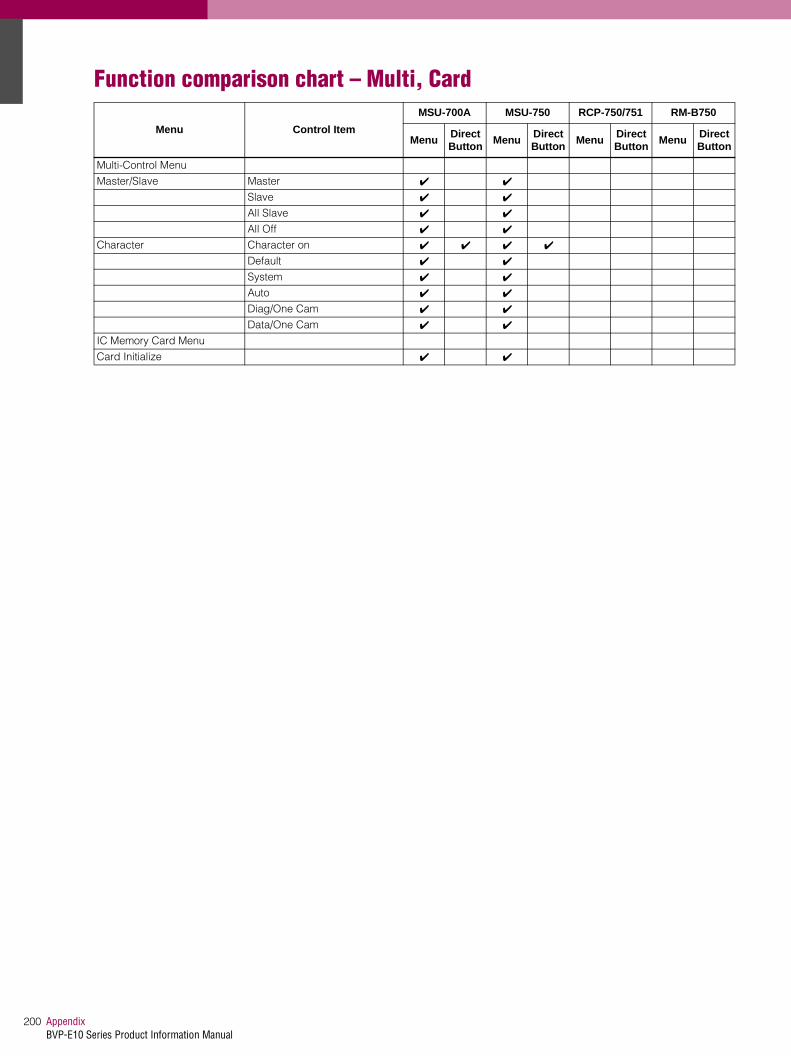
AppendixBVP-E10 Series Product Information Manual
200
Function comparison chart – Multi, Card
Menu Control Item
MSU-700A MSU-750 RCP-750/751 RM-B750
Menu Direct Button
Menu Direct Button
Menu Direct Button
Menu Direct Button
Multi-Control Menu
Master/Slave Master ✔ ✔
Slave ✔ ✔
All Slave ✔ ✔
All Off ✔ ✔
Character Character on ✔ ✔ ✔ ✔
Default ✔ ✔
System ✔ ✔
Auto ✔ ✔
Diag/One Cam ✔ ✔
Data/One Cam ✔ ✔
IC Memory Card Menu
Card Initialize ✔ ✔

201AppendixBVP-E10 Series Product Information Manual
Function comparison chart – Button and KnobButton MSU-700A MSU-750 RCP-750/751 RM-B750
All ✔ *4 ✔ *4
CAM PW ✔ *4 ✔ *4 ✔ *4
VF PW ✔ *4 ✔ *4
Signal output select✔ *4
TEST1/TEST2/BARS
✔ *4
TEST/BARS✔ *4
TEST/BARS✔ *4
TEST/BARS
CLOSE ✔ *4 ✔ *4 ✔ *4 ✔ *4
STANDARD ✔ *4 ✔ *4 ✔ *4 ✔ *4
AUTO SETUP SKIN DTL AUTO HUE ✔ ✔ ✔ *4
LEVEL ✔ ✔ ✔ *4
START/BREAK ✔ ✔ ✔
WHITE ✔ ✔ ✔ *4 ✔
BLACK ✔ ✔ ✔ *4 ✔
Camera/CCU function ON/OFF KNEE off ✔
DETAIL off ✔
LVL DEP off ✔
GAMMA off ✔
CHROMA off ✔
MATRIX off ✔
KNEE APERTURE ✔
KNEE SAT ✔ ✔ *1
MONO COLOR ✔
COLOR CORRECT ✔
5600K ✔ ✔ ✔ ✔ *1
AUTO KNEE ✔ ✔ ✔ ✔ *1
SKIN DETAIL ✔ ✔ ✔ ✔ *1
DETAIL GATE ✔ ✔
SATURATION ✔
CONTRAST ✔
BLACK GAMMA ✔ ✔ ✔ *1
CHARACTER ✔ ✔ ✔ *4
SD MATRIX off ✔
SD DETAIL off ✔
LOW KEY SAT ✔
Scene File Control SCENE FILES ✔ ✔
STORE ✔ ✔
PICTURE MONITOR ✔ *4 ✔ *4
WAVEFORM MONITOR ✔ *4 ✔ *4
Camera Select PANEL ACTIVE ✔ *4 ✔ *4
PARA ✔ *4 ✔ *4 ✔ *4
EXPAND ✔ *4 ✔ *4
MASTER ✔ *4
SLAVE ✔ *4
Filter control FILTER CTRL ✔
ND ✔
CC ✔
ECS/Shutter select ✔
Gamma select ✔
Master gain select ✔
IRIS/MB ACTIVE ✔ *4 ✔ *4 ✔ *4
MASTER BLACK control knob ✔ ✔ ✔ ✔
MASTER BLACK RELATIVE ✔ *4
Iris Control knob ✔ *4 ✔ *4 ✔ *4 ✔ *4
CALL ✔ *4 ✔ *4 ✔ *4 ✔ *1&*4

AppendixBVP-E10 Series Product Information Manual
202
Note*1 Available w/VTR function SW (selectable when in the ENG Mode in the menu)*2 Available w/Black knob (selected from the menu)*3 Available w/Menu Mode buttons by pressing the MONITOR button*4 Accessible only with switches or knobs on the control panel
Auto Iris ✔ ✔ ✔ ✔
IRIS RELATIVE ✔ *4
SENS control ✔ *4
COARSE control ✔ *4
WHITE knobs ✔ ✔ (R,B)
BLACK knob✔
(R,G,B,Master)✔ (R,B,Master)
FLARE knob ✔ *2
PANEL ACTIVE Full<->Lock ✔ *4 ✔ *4
Full<->Part<->Lock ✔ *4
DETAIL knob ✔
VTR START/STOP ✔ *4
STOP ✔ *4
REW ✔ *4
PLAY ✔ *4
FF ✔ *4
REC REVIEW ✔ *4
MONITOR ✔ *4
FUNCTION (Menu Mode) ✔ *4
MAINTENANCE (Menu Mode) ✔ *4
SCENE (Menu Mode) ✔ *4
PAINT (Menu Mode) ✔ *4
VF DISP ✔ *3&*4
VF MENU ✔ *3&*4
CANCEL ✔ *3&*4
ENTER ✔ *3&*4
Button MSU-700A MSU-750 RCP-750/751 RM-B750

