studies of the effect of ground settlement on the buried ...members.igu.org/old/igu...
TRANSCRIPT
0
International Gas Union Research Conference, September 2014, Copenhagen
Studies of the effect of ground settlement on the buried pipe including a part passing through the building wall
Tetsuji KITANO1, Toshihiro NONAKA1, Shusuke FUJITA2
1 Disaster Mitigation Research Center, Nagoya University, Japan 2 Nippon Steel & Sumikin Pipeline & Engineering, Japan

1
TABLE OF CONTENTS ABSTRACT ...................................................................................................................... 2 1. Background .................................................................................................................. 2 2. Aims ............................................................................................................................. 2 3. Methods ....................................................................................................................... 3 4. Results ......................................................................................................................... 5 4.1 Outline of the case study ............................................................................................ 5 4.2 Piping having two bends ............................................................................................ 5 4.3 Piping having three bends .......................................................................................... 7 5. Conclusions ................................................................................................................ 10 Acknowledgements ........................................................................................................ 11 REFERENCES .............................................................................................................. 11

2
ABSTRACT Wide or local deformation of the buried pipe line occurs by the change in ground condition
caused by various reasons. For example, at the time of earthquakes, lateral spreading and also subsidence of the ground are produced by liquefactions caused by strong ground motion. A buried pipe line in which large strain and large stress are produced by the subsidence of the ground is the pipe line including a piping through the penetration part of a wall hole in buildings or abutments. In this study, in order to discuss the most suitable buried pipe line configuration including the building penetration piping, numerical case studies are performed for various types of buried pipe lines including the building penetration piping. And then, by discussing the results of numerical case studies, the tendency of whole pipe line system, appropriate allocation of bend and length of straight pipe are discussed from the standpoint for safety.
1. Background Cogeneration System(hereinafter referred to as CGS), that is the overall highly efficient
energy-saving facility, was introduced in the 1980s in Japan and spread speedy afterwards. CGS is the excellent energy system which provides us more than two kinds of energy,
namely electricity, heat and so on, continuously at the same time from fuels. The status of CGS adoption in Japan at present is as follows. The total number of sites until
the end of March 2014 is 15,127, and the amount is 10,046 MW in total1). Since the East Japan Big Earthquake Disaster, CGS is expected as the effective power
source. And it is placed more important position in Japanese energy policy. With the assistance of energy network and information and communication technologies, the
electricity and the heat generated by the decentralized energy systems including CGS are utilized more effectively between each area and also between each building. This is expected the realization of bigger energy saving, minimize CO2 discharge and improvement of the energy security2). As the matter of course, in case that the CGS which operates on city gas is set as the
emergency electric power supply unit, the city gas pipe line should satisfy the standard prescribed by the Fire Services Act. The standard for the privately owned electric power facility which is used as emergency power supplies such as facilities for firefighting is as follows. In the case that the privately owned electric power facility operates on gaseous fuels, the spare fuels are to be stored or the city gas is to be supplied steady even though it is attacked by a strong horizontal ground motion of 400gal which correspond to JMA seismic intensity of 6-lower caused by an earthquake3)-5).
2. Aims The most important point to be evaluated on the earthquake resistance of the buried gas

3
piping within customer’s premises and that incorporated in customer’s building is the part of the buried pipe which passing through the building wall. Because, there is a possibility to occur the ground differential subsidence caused by an earthquake. This means that the buried pipe including a part passing through the building wall has to be discussed any measure for absorbing the relative displacement caused by the ground differential subsidence. In order to absorb the relative displacement between the pipe and the ground surround it, it is very important to utilize not only welded steel pipe but also combination of bend for increasing the flexibility of the pipe line. In this paper, the numerical case studies are performed for various kinds of buried piping system including a part passing through the building wall where the displacement of the pipe is restricted by the wall hole. By comparing the results of the numerical case studies, the most appropriate allocation of bend and also length of straight pipe in the buried piping system are discussed.
3. Methods
The method and condition of this numerical analysis are shown below. The dimensions of the steel pipe are as follows: nominal diameter; 100 mm, outer diameter;
11.43 cm, wall thickness; 0.45 cm. The material of the pipe satisfy Japan Industrial Standard G, namely, JISG3452 (Carbon steel pipes for ordinary piping). The mechanical property of the pipe has bilinear relationship as shown in Figure 1. Regarding the bend, a commonly used long bend is used.
Fig. 1 Stress-strain relationship of the material of the pipe In the pipeline deformation analysis caused by ground subsidence, ground displacements
are statically transferred to pipelines through soil springs. Soil spring characteristics are modeled by a bilinear relationship of restraint forces exerted upon pipelines and the relative displacements of the ground and the pipeline. Figure 2 shows soil springs in three directions. Figure 3 shows the bilinear relationship of soil reaction characteristics. In this numerical analysis, a FEM code which is called an ABAQUS Ver. 6. 12 is used. The
Element used in this FEM analysis is a 4 nodes shell element. The shell element dividing of this FEM analysis model is shown in Table 1 and Figure 4.
1
E
λE 1
εy
σy
Strain (%)
Stre
ss (N
/cm
2 ) E = 2.06×10⁷N/cm2 λ =0.007 εy = 0.12%

4
相対変位 Δ(cm)
σcr
Δcr
=0.77kgf/cm3k 2
=2.0kgf/cm2σcr
応力
σ(kgf/cm )
2
k2
2 相対変位 Δ(cm)
τcr
Δcr
k1
3
=0.13kgf/cm2τcr
=0.6kgf/cmk1
応力τ
(kgf/ c
m )
2
1
(a) Axial direction (b) Transverse direction
Transverse horizontal direction
Transverse vertical direction
Axial direction
Relative displacement Δ
The Allowable value of the pipe is limited by the critical equivalent plastic strain. The Allowable value is 2 percent for straight pipe, and 5 percent for bend.
Fig. 2 Images of the soil springs in three directions
Fig. 3 Soil reaction characteristics
Table 1 Shell element dividing of FEM analysis model
Circumferential direction Axial direction
Straight pipe 36 divide/(10°pitch)
Divide at about 1 cm
bend pipe Curvature : 5°pitch (18 divide/90°bend)
τcr(Critical shear stress)=1.0N/cm2 k1=6.0N/cm3
Δcr=0.16cm Δcr=0.5cm
σcr(Maximum restraint force)=5.0N/cm2 k2=14.3N/cm3
Relative displacement Δ Res
train
t for
ce τ
(N/c
m2 )
Res
train
t for
ce σ
(N/c
m2 )
5
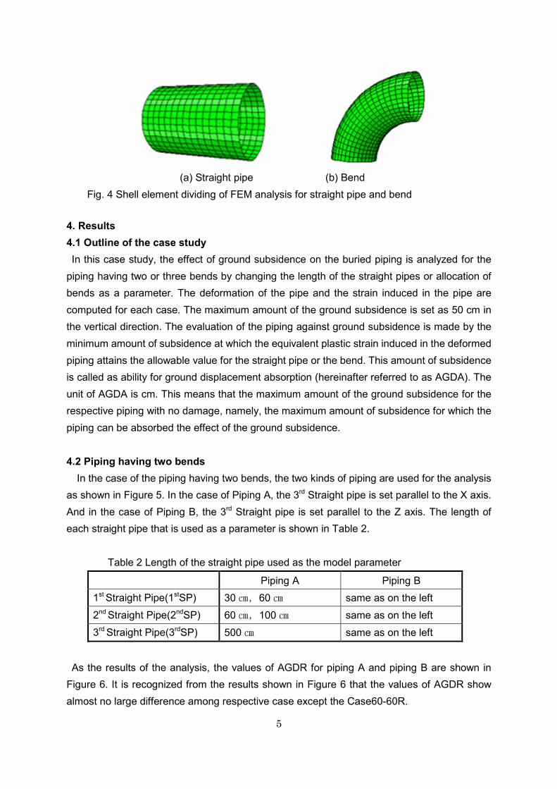
(a) Straight pipe (b) Bend
Fig. 4 Shell element dividing of FEM analysis for straight pipe and bend 4. Results 4.1 Outline of the case study In this case study, the effect of ground subsidence on the buried piping is analyzed for the piping having two or three bends by changing the length of the straight pipes or allocation of bends as a parameter. The deformation of the pipe and the strain induced in the pipe are computed for each case. The maximum amount of the ground subsidence is set as 50 cm in the vertical direction. The evaluation of the piping against ground subsidence is made by the minimum amount of subsidence at which the equivalent plastic strain induced in the deformed piping attains the allowable value for the straight pipe or the bend. This amount of subsidence is called as ability for ground displacement absorption (hereinafter referred to as AGDA). The unit of AGDA is cm. This means that the maximum amount of the ground subsidence for the respective piping with no damage, namely, the maximum amount of subsidence for which the piping can be absorbed the effect of the ground subsidence. 4.2 Piping having two bends In the case of the piping having two bends, the two kinds of piping are used for the analysis
as shown in Figure 5. In the case of Piping A, the 3rd Straight pipe is set parallel to the X axis. And in the case of Piping B, the 3rd Straight pipe is set parallel to the Z axis. The length of each straight pipe that is used as a parameter is shown in Table 2.
Table 2 Length of the straight pipe used as the model parameter
Piping A Piping B 1st Straight Pipe(1stSP) 30 ㎝,60 ㎝ same as on the left 2nd Straight Pipe(2ndSP) 60 ㎝,100 ㎝ same as on the left 3rd Straight Pipe(3rdSP) 500 ㎝ same as on the left
As the results of the analysis, the values of AGDR for piping A and piping B are shown in
Figure 6. It is recognized from the results shown in Figure 6 that the values of AGDR show almost no large difference among respective case except the Case60-60R.

6
Piping A (in-plane piping) Piping B (out-of-plane piping)
Figure 5 Piping models having two bends
Figure 6 Ability for ground displacement absorption
Figure 7 Deformation of the pipe for Case30-100S
Piping A Piping B
Analysis Case
Horizontal Axis Legend: 30-60S
1stStraight Pipe length (cm) -2ndStraight Pipe length (cm)
-S: X-axis direction -R: Z-axis direction
1st Straight pipe 1st Bend 2nd Straight pipe 2nd Bend 3rd Straight pipe
1st Straight pipe 1st Bend 2nd Straight pipe 2nd Bend 3rd Straight pipe
Abilit
y fo
r gro
und
dis
plac
emen
t abs
orpt
ion
(cm
)

7
The mechanism to absorb ground movement in piping system is considered as follows. The 2nd Bend which is placed most away from the fixed point deforms so called outward bending deformation. This deformation leads the change in inclination and bending of the straight pipes those are connected to the both side of the bend. These deformations absorb the ground movement by the subsidence. As an example, figure 7 shows the deformation of the pipe, and Figure 8 show the equivalent plastic strain induced in the pipe and the deformations.
Case30-60S Case30-100S
Figure 8 Equivalent plastic strain and deformation (The initial shape is shown with gray) 4.3 Piping having three bends In case of the piping having three bends, the two kinds of piping are used for the analysis as
shown in Figure 9. In the case of Piping C, the 2nd Straight pipe is set vertically. And in the case of Piping D, the 2nd Straight pipe is set horizontally. The length of each straight pipe that is used as a parameter is shown in Table 2. The values of AGDR for piping C are shown in Figure 10.
Piping C (Vertical piping) Piping D (Horizontal piping)
Figure 9 Piping Models having three bends
2ndStraight pipe
1st Straight Pipe 1st Bend
2nd Bend
3rd Bend
2nd Straight
3rd Straight Pipe
4th Straight Pipe

8
Table 2 Length of the straight pipe used as the model parameter
Piping C Piping D
1stStraight Pipe(1stSP) 30 ㎝,60 ㎝,100 ㎝ 30 ㎝,60 ㎝ 2ndStraight Pipe(2ndSP) 60 ㎝,100 ㎝,150 ㎝ same as on the left
3rdStraight Pipe(3rdSP) 60 ㎝,100 ㎝,150 ㎝ same as on the left
4thStraight Pipe(4thSP) 10m same as on the left
Figure 10 Ability for ground displacement absorption of piping C
It is very clearly recognized from the results shown in Figure 10 that the AGDR for the case of 1stSP=100 cm becomes very poor compared with that for the case of 1stSP=30 cm and 1stSp=60 cm. This comes from the reason that the 1st straight pipe can be regarded as a kind of a cantilever from the stand point of the structural mechanics. Figure 11 shows deformation of the piping C and the distribution of equivalent plastic strain induced in the pipe. In this figure, the initial shape of piping is shown with gray. As shown in Figure 11, increase in the length of the 1st straight pipe increases the bending moment at the fixed point logically having no relation with the length of the 2nd and 3rd straight pipes. In cases of 1stSP=30 cm and 1stSP=60 cm, the rigidity of the 1st SP suppress the increase of the plastic deformation at the fixed point. It is recognized from the results shown in figure 10 that the values of the AGDR for the case of 3rd SP=60 cm is much larger than the others. Figure 12 shows the deformations of the piping and induced equivalent plastic strain for the case of interest. The initial shape of piping is shown with gray. As shown in this figure, the effect of subsidence on the piping is absorbs gently in the long range of the piping in the case that the length the 3rd Straight pipe is short
1stSP:30 ㎝ 1stSP:60 ㎝ 1stSP:100 ㎝
Analysis Case
Abilit
y fo
r gro
und
dis
plac
emen
t abs
orpt
ion
(cm
)
9
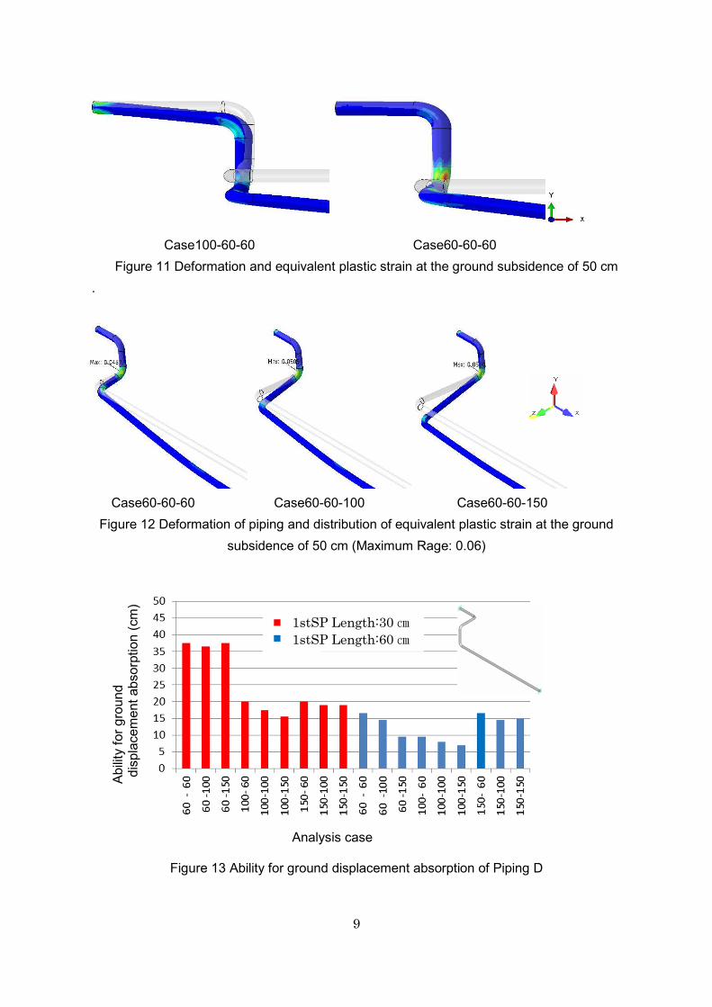
Case100-60-60 Case60-60-60 Figure 11 Deformation and equivalent plastic strain at the ground subsidence of 50 cm .
Case60-60-60 Case60-60-100 Case60-60-150
Figure 12 Deformation of piping and distribution of equivalent plastic strain at the ground subsidence of 50 cm (Maximum Rage: 0.06)
Figure 13 Ability for ground displacement absorption of Piping D
1stSP Length:30 ㎝ 1stSP Length:60 ㎝
Analysis case
Abilit
y fo
r gro
und
dis
plac
emen
t abs
orpt
ion
(cm
)
10
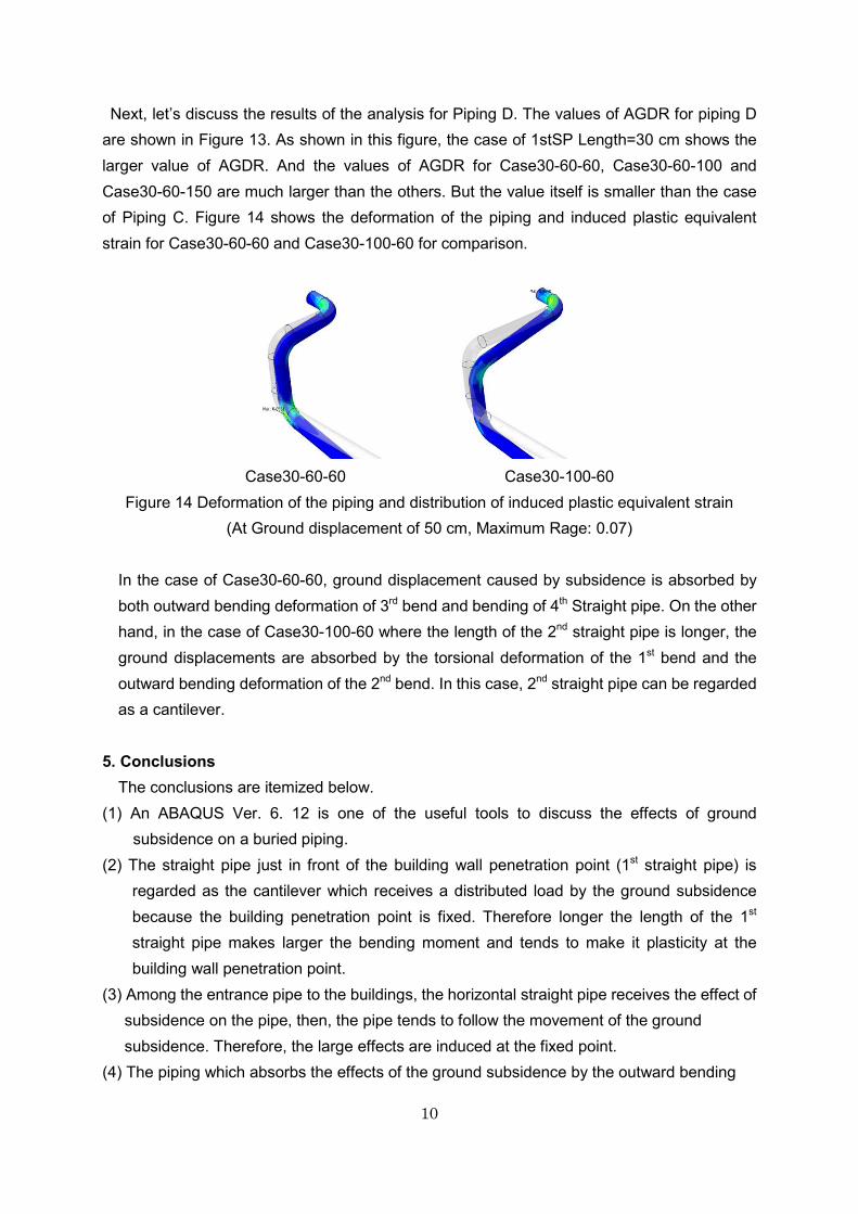
Next, let’s discuss the results of the analysis for Piping D. The values of AGDR for piping D are shown in Figure 13. As shown in this figure, the case of 1stSP Length=30 cm shows the larger value of AGDR. And the values of AGDR for Case30-60-60, Case30-60-100 and Case30-60-150 are much larger than the others. But the value itself is smaller than the case of Piping C. Figure 14 shows the deformation of the piping and induced plastic equivalent strain for Case30-60-60 and Case30-100-60 for comparison.
Case30-60-60 Case30-100-60
Figure 14 Deformation of the piping and distribution of induced plastic equivalent strain (At Ground displacement of 50 cm, Maximum Rage: 0.07)
In the case of Case30-60-60, ground displacement caused by subsidence is absorbed by both outward bending deformation of 3rd bend and bending of 4th Straight pipe. On the other hand, in the case of Case30-100-60 where the length of the 2nd straight pipe is longer, the ground displacements are absorbed by the torsional deformation of the 1st bend and the outward bending deformation of the 2nd bend. In this case, 2nd straight pipe can be regarded as a cantilever.
5. Conclusions The conclusions are itemized below. (1) An ABAQUS Ver. 6. 12 is one of the useful tools to discuss the effects of ground
subsidence on a buried piping. (2) The straight pipe just in front of the building wall penetration point (1st straight pipe) is
regarded as the cantilever which receives a distributed load by the ground subsidence because the building penetration point is fixed. Therefore longer the length of the 1st straight pipe makes larger the bending moment and tends to make it plasticity at the building wall penetration point.
(3) Among the entrance pipe to the buildings, the horizontal straight pipe receives the effect of subsidence on the pipe, then, the pipe tends to follow the movement of the ground subsidence. Therefore, the large effects are induced at the fixed point.
(4) The piping which absorbs the effects of the ground subsidence by the outward bending

11
deformation of the 2nd Bend and the after and also absorbs the bending or inclination of the straight pipe is desirable for the piping close to the building penetration point.
(5) The piping having three bends absorbs the effect of ground subsidence more smoothly than the piping having two bends. This means that the increase in the number of the bend in the piping decrease the possibility of the damage of the piping by ground subsidence caused by liquefaction induced by big earthquakes.
(6) As the subject in the future based on this case study is as follows: discuss the modeling of the bend by use of plasticity hinges, and proceed making of the design methods for the entrance pipe to the buildings.
Acknowledgements
This work was financially supported by JSPS KAKENHI No.25282118.
REFERENCES 1. Advanced Cogeneration and Energy Utilization Center Japan, CHP Current State in
Japan,( http://www.ace.or.jp/web/works/works_0010.html) 2. Advanced Cogeneration and Energy Utilization Center Japan, Cogeneration System,
2013.1 3. Japan Engine Generator Association, The situation of Gas Supply System for Dedicated
Gas-Burning Power Generating Facilities in the Great East Japan Earthquake, Japan Engine Generator Association NEWS,(March,2012)
4. Japan Engine Generator Association, Evaluation Result of Gas Supply System for Dedicated Gas-Burning Power Generating Facilities (January,2014~March,2014), Japan Engine Generator Association NEWS (January,2014)
5. Japan Engine Generator Association, Evaluation Result of Gas Supply System for Dedicated Gas-Burning Power Generating Facilities, Japan Engine Generator Association NEWS,2014.4