student launch competition 2017-2018 - umbra
TRANSCRIPT

Student Launch Competition 2017-2018

California State Polytechnic University, Pomona | 2017-2018 NSL
1
Table of Contents 1 General Information .......................................................................................................... 6
1.1 Adult Educators and Mentor .......................................................................................... 6
1.2 Safety Officer ................................................................................................................. 6
1.3 Lead Engineer ................................................................................................................ 6
1.4 Team Members ................................................................................................................ 6
1.5 NAR Association ............................................................................................................. 7
2 Summary of CDR Report ................................................................................................. 8
2.1 Team Summary .............................................................................................................. 8
2.2 Launch Vehicle Summary.............................................................................................. 8
2.3 Milestone Review Flysheet ............................................................................................ 8
2.4 Payload Experiment Summary ...................................................................................... 8
3 Changes Made Since PDR ................................................................................................ 9
3.1 Vehicle Criteria Changes ............................................................................................... 9
3.2 Payload Criteria Changes ............................................................................................. 10
3.3 Project Plan Changes ................................................................................................... 10
4 Vehicle Criteria ............................................................................................................... 11
4.1 Design and Verification of Launch Vehicle ................................................................... 11
4.1.1 Mission Statement and Mission Success Criteria ................................................. 11
4.1.2 Final Design: Chosen Components and Justification ............................................... 12
4.1.3 Subsystem and Component Drawings and Specifications ........................................ 14
4.1.3.1 Structures Subsystem ................................................................................... 14
4.1.3.2 Propulsion Subsystem .................................................................................. 17
4.1.3.3 Aerodynamics Subsystem ............................................................................ 22
4.1.3.4 Recovery Subsystem .................................................................................... 25
4.1.3.5 Payload Subsystem ...................................................................................... 27
4.1.4 CAD Drawings: Final Launch Vehicle .................................................................... 29
4.1.5 System Level Requirements and Risk Compliance .................................................. 29
4.1.6 Design Integrity ...................................................................................................... 31
4.1.6.1 Suitability of Shape and Fin Style ................................................................ 31
4.1.6.2 Materials Compliance ................................................................................... 32

California State Polytechnic University, Pomona | 2017-2018 NSL
2
4.1.6.3 Motor Mounts and Retention ....................................................................... 33
4.1.6.4 Final Mass of Launch Vehicle ..................................................................... 34
4.2 Subscale Flight Results .................................................................................................. 36
4.2.1 Data Gathering Devices ........................................................................................ 36
4.2.2 Apogee and Other Flight Data ................................................................................. 36
4.2.3 Scaling Factors ....................................................................................................... 38
4.2.4 Launch Day Conditions and Simulation ............................................................... 39
4.2.5 Subscale Flight Analysis ....................................................................................... 39
4.2.5.1 Predicted vs Actual Flight Data and Error .................................................. 39
4.2.5.2 Drag Coefficient Estimation ........................................................................ 41
4.2.6 Subscale Flight Data Impact ................................................................................. 42
4.3 Recovery Subsystem...................................................................................................... 44
4.3.1 Final Recovery Design and Justification .............................................................. 44
4.3.2 Parachute Design .................................................................................................... 45
4.3.3 Harness Design ....................................................................................................... 49
4.3.4 Attachment Hardware Design ............................................................................... 50
4.3.5 Electrical Components Design: GPS .................................................................... 52
4.3.5.1 Drawings and Sketches ................................................................................ 54
4.3.5.2 Block Diagrams ........................................................................................... 55
4.3.5.3 Electrical Schematics ................................................................................... 56
4.3.6 Electrical Components Design: Altimeters ........................................................... 56
4.3.6.1 Drawings and Sketches ................................................................................ 57
4.3.6.2 Block Diagrams ........................................................................................... 58
4.3.6.3 Electrical Schematics ................................................................................... 58
4.3.7 Electrical Component Redundancy: GPS and Altimeters .................................... 59
4.3.8 Operating Frequency of Locating Trackers .......................................................... 59
4.4 Mission Performance Predictions ................................................................................... 59
4.4.1 Flight Profile Simulations ..................................................................................... 59
4.4.2 Simulated Motor Thrust Curve ................................................................................ 61
4.4.3 Altitude Predictions ................................................................................................ 62
4.4.4 Center of Pressure and Gravity ............................................................................. 64

California State Polytechnic University, Pomona | 2017-2018 NSL
3
4.4.5 Stability Margin ..................................................................................................... 66
4.4.6 Kinetic Energy ........................................................................................................ 68
4.4.7 Drift Calculations .................................................................................................. 68
5 Safety ............................................................................................................................... 70
5.1 Launch Concerns and Operation Procedures ............................................................... 70
5.1.1 Recovery Preparation ............................................................................................ 70
5.1.2 Motor Preparation ................................................................................................. 72
5.1.3 Setup on Launcher ................................................................................................. 72
5.1.4 Igniter Installation ................................................................................................. 73
5.1.5 Troubleshooting..................................................................................................... 74
5.1.6 Post-Flight Inspection ........................................................................................... 74
5.2 Safety and Environment: Vehicle and Payload ........................................................... 75
5.2.1 Personnel Hazard Analysis ................................................................................... 77
5.2.2 Failure Modes and Effects Analysis ..................................................................... 83
5.2.3 Environmental Hazard Analysis ........................................................................... 87
5.2.4 Safety Officer Identified Responsibilities ............................................................. 91
6 Payload Criteria: Design of Payload Equipment ............................................................ 92
6.1 Final Design: Components and Justification ............................................................... 92
6.1.1 Deployment System .............................................................................................. 92
6.1.2 Solar Panels ........................................................................................................... 93
6.1.3 Avionics ................................................................................................................ 93
6.2 System Level Design .................................................................................................... 95
6.2.1 Payload Assembly ................................................................................................. 95
6.2.2 Component Drawings and Specifications ............................................................. 97
6.2.2.1 Deployment System ................................................................................. 100
6.2.2.2 Solar Panels .............................................................................................. 102
6.2.3 Payload Component Interactions ........................................................................ 106
6.2.4 Payload Integration to Launch Vehicle .............................................................. 106
6.3 Payload Derived Requirements and Risk Matrix ....................................................... 107
6.4 Payload Electronics ..................................................................................................... 109
6.4.1 Payload Electronics Overview ............................................................................ 109

California State Polytechnic University, Pomona | 2017-2018 NSL
4
6.4.1.1 Drawings and Schematics ........................................................................ 109
6.4.1.2 Block Diagrams ........................................................................................ 111
6.4.1.3 Batteries/power ......................................................................................... 112
6.4.1.4 Switch and Indicator Wattage and Location ............................................ 112
7 Project Plan .................................................................................................................. 113
7.1 Test Plans ................................................................................................................. 113
7.1.1 Launch Vehicle Test Plans ................................................................................. 113
7.4.1.1 Subscale Launch Test ............................................................................... 113
7.4.1.2 Full-scale Launch Test ............................................................................. 115
7.4.1.3 Bulkhead Test ........................................................................................... 116
7.4.1.4 PLA Materials Test .................................................................................. 118
7.4.1.5 Observation System Test ......................................................................... 119
7.1.2 Recovery System Test Plans ............................................................................. 120
7.1.2.1 Parachute Drop Test ................................................................................. 120
7.1.2.2 Ejection Charge Test ................................................................................ 121
7.1.2.3 Recovery Avionics Shielding Test ........................................................... 123
7.1.3 Payload Test Plans ............................................................................................. 123
7.1.3.1 Payload Integration Test ........................................................................... 123
7.1.3.2 Raspberry Pi Test ..................................................................................... 125
7.1.3.3 GPS Test ................................................................................................... 125
7.1.3.4 Xbee .......................................................................................................... 125
7.2 Requirements Compliance ....................................................................................... 126
7.2.1 Launch Vehicle Compliance Matrix ................................................................. 126
7.2.2 Recovery System Compliance Matrix .............................................................. 139
7.2.3 Payload Compliance Matrix .............................................................................. 144
7.2.4 Safety Compliance Matrix ................................................................................ 145
7.2.5 General Compliance Matrix .............................................................................. 148
7.2.6 Derived Requirements Compliance Matrix ...................................................... 154
7.3 Budget Plan .............................................................................................................. 158
7.3.1 Full Scale Launch Vehicle Expenses ................................................................ 158
7.3.2 Sub Scale Launch Vehicle Expenses ................................................................ 160

California State Polytechnic University, Pomona | 2017-2018 NSL
5
7.3.3 Payload Expenses .............................................................................................. 162
7.3.4 Educational Engagement Expenses................................................................... 163
7.3.5 Travel Expenses ................................................................................................ 163
7.3.6 Other Expenses .................................................................................................. 164
7.3.7 Overall Expenses ............................................................................................... 165
7.3.8 Funding Plan ...................................................................................................... 165
7.4 Timeline .................................................................................................................... 166
7.4.1 Gantt Chart ........................................................................................................ 166
7.4.2 Important Milestones ......................................................................................... 169
8 Educational Engagement ............................................................................................. 172

California State Polytechnic University, Pomona | 2017-2018 NSL
6
1.0 General Information 1.1 Adult Educators and Mentor
Donald L. Edberg, Ph.D. [email protected] (909) 869-2618
Dr. Donald Edberg serves as the faculty advisor for the project.
Todd Coburn, Ph.D. [email protected]
(909) 869-2235 Dr. Todd Coburn will be assisting the team as an additional adult educator.
Rick Maschek
[email protected] (760) 953-0011
Rick Maschek serves as the team’s Tripoli Rocketry Association (TRA) Level 2 certified mentor with certification # 11388
1.2 Safety Officer
Natalie Aparicio Safety Officer
[email protected] (323) 919-0223
1.3 Lead Engineer Casey K. Luna Lead Engineer
[email protected] (562) 299-8525
1.4 Team Members and Participants There are 22 students with varying technological backgrounds participating in the NASA Student Launch Initiative 2017-2018 from California State Polytechnic University, Pomona. The team consists of a variety of engineering students including: aerospace, mechanical, electrical, computer, and chemical engineering. To target the specific requirements set forth in the SOW, members were carefully selected and assigned to four different sub-teams: systems, aerodynamics, structures and payload. The team’s organization is outlined in the Figure 1.4-1. A total of 17 team members will be attending the competition launch week.

California State Polytechnic University, Pomona | 2017-2018 NSL
7
Figure 1.4-1: Team member organization outline.
1.5 NAR Association The designated NAR/TRA section that will be supporting the team with their documentation review and launch assistance is the Southern Rocket Association (SCRA) section #430. The main launch site under this section is at the Lucerne Dry Lakebed in the Mojave Desert. President Martin Bowitz of the SCRA is the main contact for this section. His contact information is provided:
Martin Bowitz (Section #430) PO Box 5165
Fullerton, CA 92838 [email protected]
(714) 529-1598
California State Polytechnic University, Pomona | 2017-2018 NSL
8
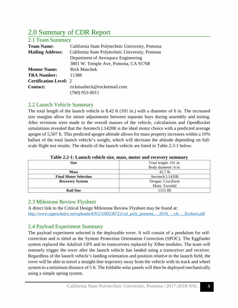
2.0 Summary of CDR Report 2.1 Team Summary Team Name: California State Polytechnic University, Pomona Mailing Address: California State Polytechnic University, Pomona Department of Aerospace Engineering 3801 W. Temple Ave, Pomona, CA 91768 Mentor Name: Rick Maschek TRA Number: 11388 Certification Level: 2 Contact: [email protected] (760) 953-0011 2.2 Launch Vehicle Summary The total length of the launch vehicle is 8.42 ft (101 in.) with a diameter of 6 in. The increased size margins allow for minor adjustments between separate bays during assembly and testing. After revisions were made to the overall masses of the vehicle, calculations and OpenRocket simulations revealed that the Aerotech L1420R is the ideal motor choice with a predicted average apogee of 5,507 ft. This predicted apogee altitude allows for mass property increases within a 10% ballast of the total launch vehicle’s weight, which will decrease the altitude depending on full-scale flight test results. The details of the launch vehicle are listed in Table 2.2-1 below.
Table 2.2-1: Launch vehicle size, mass, motor and recovery summary Size Total length: 101 in.
Body diameter: 6 in. Mass 43.7 lb
Final Motor Selection Aerotech L1420R Recovery System Drogue: Cruciform
Main: Toroidal Rail Size 1515 8ft
2.3 Milestone Review Flysheet A direct link to the Critical Design Milestone Review Flysheet may be found at: http://www.cpprocketry.net/uploads/8/9/2/3/89238722/cal_poly_pomona_-_2018_-_cdr_-_flysheet.pdf 2.4 Payload Experiment Summary The payload experiment selected is the deployable rover. It will consist of a pendulum for self- correction and is titled as the System Protection Orientation Correction (SPOC). The Eggfinder system replaced the Adafruit GPS and its transceivers replaced by XBee modules. The team will remotely trigger the rover after the launch vehicle has landed using a transceiver and receiver. Regardless of the launch vehicle’s landing orientation and position relative to the launch field, the rover will be able to travel a straight-line trajectory away from the vehicle with its track and wheel system to a minimum distance of 5 ft. The foldable solar panels will then be deployed mechanically using a simple spring system.

California State Polytechnic University, Pomona | 2017-2018 NSL
9
3.0 Changes made since PDR 3.1 Vehicle Criteria Changes The changes made to the full-scale launch vehicle are summarized below in Table 3.1-1:
Table 3.1-1: Launch vehicle changes and justifications
Criteria Changes Made Reason for Change Vehicle Size Overall length increased from
7.75 ft to 8.42 ft Main parachute bay was increased from 18 in. to 27 in. to provide for extra packing length
Vehicle Mass Overall mass decreased from 46 lb to 43.7 lb
Estimated masses were weighed after components were 3D printed or manufactured to improve accuracy; component material adjusted.
Nose Cone Material changed from PLA and fiberglass reinforcement to PLA only.
PLA alone was found to meet mission requirements; reduces cost of manufacturing.
Fin Material changed from PLA and fiberglass reinforcement to PLA only.
PLA alone was found to meet mission requirements; reduces cost of manufacturing.
Recovery GPS Redundancy added for GPS; Trackimo GPS has been added in addition to the Eggfinder
Redundancy ensures launch vehicle shall be easily recoverable in case of primary GPS failure. Tests will be conducted to ensure interference does not occur.
Drogue Parachute Size changed to 4 ft2 Descent rate has been adjusted to ensure the drift radius meets requirements.
Main Parachute Deployment altitude changed from 500 ft to 600 ft.
Original deployment altitude was found to be too low; descent rate adjustments yielded a higher altitude.
Motor Selection Motor has changed from a Cesaroni L1115 to an Aerotech L1420R
After design changes, the L1420R provides a closer apogee altitude than the previously selected L1115.

California State Polytechnic University, Pomona | 2017-2018 NSL
10
3.2 Payload Criteria Changes The changes to the payload were mostly done to the rover’s hardware. The GPS module will no longer be an Adafruit module, but is now a standalone Eggfinder system as it only needs to pull power from the RPi CPU. The GPS and observation avionics changes are outlined in Table 3.2-1:
Table 3.2-1: Payload experiment changes and justifications Criteria Changes Made Reason for Change GPS Module Adafruit module replaced by
the Eggfinder system; Adafruit transceivers replaced by XBee modules.
Ensures ease of setup and use; the XBee on the rover will be connected to the RPi via an XBee shield, which makes integration much easier.
Payload Observation Avionics
Live video feed and camera eliminated: The ground station will now consist of a laptop with the Eggfinder RX and the ground XBee both connected independent from one another via USB.
Due to size limitations of the rover: The feed did not provide enough benefit to justify the cost, size and difficulty added to the rover; Eliminated the need to build another RPi as needed in the previous design.
3.3 Project Plan Changes There were only minor changes made to the project plan. Due to the alterations made to the vehicle and payload criteria, the full-scale launch vehicle expenses were adjusted. A detailed list can be found in the budget plan section 7.3.1.

California State Polytechnic University, Pomona | 2017-2018 NSL
11
4.0 Vehicle Criteria 4.1 Design and Verification of Launch Vehicle
4.1.1 Mission Statement and Mission Success Criteria The team’s mission is to successfully build, test, and fly an efficient, safe, and stable launch vehicle that will contain a deployable rover with solar panels to an apogee of 5,280 feet. For mission success, the launch vehicle must meet the following criteria listed in Table 4.1.1-1:
Table 4.1.1-1: Launch vehicle mission success criteria
Mission Success Criteria Goal
Peak Altitude Reach the required peak altitude of 5,280 feet AGL within the range of ±50 feet.
Stability Margin The center of gravity must be ahead of the center of pressure for the rocket to be stable, so rocket will be optimized to be in the stability margin range of 2 to 3.
Main Parachute and Drogue Parachute Deployment
The main parachute and drogue parachute will deploy at their necessary altitudes.
Horizontal Drift The rocket will descend safely into the required 2,500 ft recovery radius.
Kinetic Energy upon impact
By minimizing the descent velocity, the rocket will make land with kinetic energy lower than 75 foot-pounds.
Payload safety Through vehicle and payload design, the payload will be secured safely and will able to complete its mission without any damages.
Rocket reusability The rocket will be designed to withstand the forces during launch and flight and will be able to be used again without modifications or repairs after landing.

California State Polytechnic University, Pomona | 2017-2018 NSL
12
Payload success The deployable rover will be successfully able to navigate 5 feet away from the launch vehicle at landing and will be able to deploy solar panels.
4.1.2 Final Design: Chosen Components and Justification
Launch Vehicle Geometry Final Design Having conducted all trade studies in the preliminary design and having gathered all required dimensions for each bay, the final leading design is as follows: The launch vehicle will have a length of 101 in., a uniform 6 in. diameter body tube, an L1420R motor, a Von Karman nose cone, three clipped delta fins, and an overall weight of approximately 43.3 lb. The observation system will use a Raspberry Pi Zero. The recovery system consists of a cruciform drogue parachute and a toroidal main parachute, which will both be ejected from their respective bays using ejection charges controlled by PerfectFlite StratoLogger altimeters. The launch vehicle’s tracking system is comprised of an Eggfinder GPS system housed alongside the observation system. From the tip of the nose cone to the aft end of the vehicle, the major bays are as follows: Nose cone, Payload Bay, Main Parachute Bay, Recovery Avionics Bay, Drogue Parachute Bay, Observation Bay, and the Motor bay with its fin integration. A clear image of the configuration can be seen in Figure 4.1.2-1.
Figure 4.1.2-1: Overview of the launch vehicle
Nose Cone Final Design A Von Karman, LD Haack, nose cone design was chosen for the rocket for the final design, as it was the leading alternative in the trade study that was conducted in the preliminary design. This design’s low drag coefficient and weight of 3.04 lbs. have made this nose cone the optimal design out of the three traded nose cone designs. The nose cone will be 6 inches in diameter and 12 inches in length with a thickness of 0.25 inches. The material chosen for the nose cone is PLA, which will be manufactured on campus with the use of 3D printers.

California State Polytechnic University, Pomona | 2017-2018 NSL
13
Fin Final Design The clipped delta shape was selected as the leading alternative from the Preliminary Design Review, and will be the final design used for the launch vehicle. The clipped delta shaped fin is constructed using simple geometry, which in turn, increases manufacturability. Its swept design yields a gradual pressure distribution, as well as a low drag coefficient. The fin integration system will allow for the fins to be dropped into the launch vehicle in a convenient manner. The fins can be replaced on the field using only a screwdriver. The design minimizes downtime to achieve more flight time. Propulsion Subsystem Final Design Out of the traded motors in the preliminary design, none were ultimately chosen. As a result of the launch vehicle’s final weight decreasing from 46 lb to 43.7 lb, the Aerotech L1420R became the motor of choice. It decreased the apogee altitude closer to the required 5,280 ft while still being in the acceptable range to benefit from a ballasted configuration if one is needed. It is also available from multiple vendors with hardware readily available. This motor ultimately became the most desirable to fulfill the main apogee requirement. Main Parachute Final Design The final design of the main parachute is to be a toroidal shaped parachute. This design was the leading alternative due to its high coefficient of drag value, which is needed to satisfy the kinetic energy requirement. Additionally, the 1.1 oz. Mil-spec nylon used for this parachute offers high strength and low weight, as well as a small packing factor. Drogue Parachute Final Design For the drogue parachute, the final design chosen was of a cruciform shape. This shape offers high stability and has the least amount of drift during descent. Stability was an important consideration in the design selection because of the criticality of keeping the payload safe. Recovery Altimeter Final Design The PerfectFlite StratoLogger CF was chosen as the final design of the recovery altimeter because of its ease of use and integration, as well as its cost efficiency. Additionally, the StratoLogger CF has programmable altitude for parachute deployment in one-foot increments. Two altimeters will be included in the recovery bay houses for redundancy. GPS Final Design The Eggfinder was the leading alternative and was chosen as the final Tracking GPS design chosen. In addition to the Eggfinder, a Trackimo GPS was also chosen for redundancy. Eggfinder was the optimal choice because of its cost efficiency and simple integration. Trackimo has been included as a redundant tracking system due to its ability to connect to any cellular tower, which in theory has an infinite range if cellular signal is strong in the launch area.

California State Polytechnic University, Pomona | 2017-2018 NSL
14
Observation Electronics Final Design The final design for the observation electronics consists of a Raspberry Pi Zero, a PKCELL USB Battery Pack, and a Raspberry Pi Camera Module V2. It was found that this combination offers the highest quality video while maintaining the price, weight, power requirements, and dimensions of the observation system low. The low power requirements, and the battery selected, will also ensure that the camera remains operational during the launch vehicle’s time on the launch pad, and throughout its flight. A 32GB Micro SD card with the NOOBS operating system preinstalled will be used to store the video captured by the camera. The operating system will allow for greater compatibility with, and easier use of, the Raspberry Pi Zero. 4.1.3 Subsystem and Component Drawings and Specifications
4.1.3.1 Structures Subsystem
Airframe/body In the final design, the launch vehicle’s airframe will be constructed out of 6 in. diameter Blue Tube 2.0. Blue Tube 2.0 was selected for its vulcanized fiber material which makes it capable to withstand Mach forces, more than what the rocket will experience. There will be a total of four bays that will be part of the airframe; the Payload Bay, the Main Parachute Bay, the Drogue Parachute Bay, and the Motor Bay. The Payload Bay will require a length 12 in. to house the SPOC system and the DERIC rover, the Main Parachute Bay will require a length of 26 in. to fit the main parachute along with all required hardware, the Drogue Parachute Bay will require a length of 17 in. to fit the drogue chute along with all required hardware, and the Motor bay will require a length 33 in. to house the motor and motor assembly. Figure 4.1.3.1-1 displays the configuration and dimension of each bay.
Figure 4.1.3.1-2: Launch vehicle airframe overview

California State Polytechnic University, Pomona | 2017-2018 NSL
15
Couplers For every cut made on the airframe a coupler will used to keep each section of launch vehicle connected. The couplers are constructed out of Blue Tube 2.0 and will have an outer diameter of 5.98 in. and an inner diameter of 5.84 in. In the final design of the launch vehicle, three 12 in. long couplers will be utilized. The first coupler will connect the Payload Bay to the Main Parachute Bay, the second will not only connect the Main Parachute Bay to the Drogue Parachute Bay but will also house the recovery avionics, and the third coupler will not only connect the Drogue Parachute Bay to the Motor Bay but will also house the GPS system as well as the observation components. Figure 4.1.3.1-2 shows how each coupler connects to each bay.
Figure 4.1.3.1-2: Coupler locations on launch vehicle
Bulkheads and Centering Rings All bulkheads and centering rings will be constructed out of ¾” Birch Plywood. There will be total of four Bulkheads and six centering rings. Each bulkhead utilized on the rocket will be manufactured to fit within the inner diameter of the couplers and will be fitted with one U-bolt to allow the connection of the parachutes’ shock cord, as can be seen in Figure 4.1.3.1-3. All centering rings utilized will be manufactured to fit within the 6 in. airframe and around a 3 in. diameter blue tube, as can be seen in Figure 4.1.3.1-4.

California State Polytechnic University, Pomona | 2017-2018 NSL
16
Figure 4.1.3.1-3: Top and side view of bulkhead
Figure 4.1.3.1-4: Centering ring dimensions

California State Polytechnic University, Pomona | 2017-2018 NSL
17
4.1.3.2 Propulsion Subsystem
Figure 4.1.3.2-1: Overview of motor bay
Figure 4.1.3.2-2: Location of thrust retainer, motor casing, and motor

California State Polytechnic University, Pomona | 2017-2018 NSL
18
Figure 4.1.3.2-3: Blue tube motor tube housing the motor casing
Fin Integration System Through-the-wall (TTW) fins will be implemented to allow for easy repairs and prevent fin shearing during acceleration. The fins extend past the body tube and connect to the centering rings via a series of slots in the body tube. This results in a strong mechanical connection between the fin and the launch vehicle. The TTW system does not affect the performance of the fin as the mechanical connections are positioned underneath body tube. Figure 4.1.3.2-1 depicts the Fin Integration System shrouded by the body tube.

California State Polytechnic University, Pomona | 2017-2018 NSL
19
Figure 4.1.3.2-1: Fin integration system shrouded by body tube
The system is very simple consisting of 4 centering rings, 3 fins, and 6 bolts. The centering ring layout is shown in Figure 4.1.3.2-2.
Figure 4.1.3.2-2: A & B Centering ring layout of fin system

California State Polytechnic University, Pomona | 2017-2018 NSL
20
It can be noted that the centering rings in the middle have cut outs or notches. The notches serve as a point of contact to the fins. A friction fit will be implemented to prevent unwanted movement. The centering rings at the end have holes to accommodate bolts. The bolts extend past the centering rings and lock into the fins. The system was designed for convenient removal of fins in case of repairs. The lack of the use of epoxy/glue ensures a clean construction. All that is required to remove a fin is a screwdriver.
Figure 4.1.3.2-3 Simple removal of fin for replacement
The complete assembly of the fin system sliding into the body tube can be seen in Figure 4.1.3.2-4. The dimensions of the fin mounting hardware are depicted in the last figure.

California State Polytechnic University, Pomona | 2017-2018 NSL
21
Figure 4.1.3.2-4: Fin integration system sliding into body tube
Figure 4.1.3.2-5: Fin mounting hardware dimensions

California State Polytechnic University, Pomona | 2017-2018 NSL
22
4.1.3.3 Aerodynamics Subsystem Fin Geometry
Three clipped delta fins were selected as the design for the launch vehicle. Dimensions made, along with a NACA 0008 design, were implemented to provide a more stable flight profile. The fins will have a root chord of 12 in., a tip chord of 6in., and a height of 7.50 in. Figures 4.1.3.3-1 and 4.1.3.3-2 provide an image of the finalized fin design.
Figure 4.1.3.3-1: Dimensioned clipped delta fin
Figure 4.1.3.3-2: Angled view displaying NACA 0008 design

California State Polytechnic University, Pomona | 2017-2018 NSL
23
Nose Cone
Table 4.1.3.3-1: Von Karman vs. Ellipsoid Nose Cone Trade Study
Von Karman Nose Cone
Ellipsoid Nose Cone
Weight: 3.04 lbs. Drag Coefficient: 0.02
Weight: 3.91 lbs. Drag Coefficient: 0.05
Pros: • Lowest Coefficient of Drag • Highest Directional Stability • Lightest Weight
Cons:
• Complex Shape
Pros: • Moderate Directional Stability • Rounded Tip
Cons:
• Highest Coefficient of Drag • Heaviest Weight
The Von Karman nose cone has been chosen for its low coefficient of drag as well as its low weight. This design will also increase the stability of the rocket and maximize its potential. The volume of the nose cone makes this design ideal for storage, making this design desirable. In the CFD analysis performed both design alternatives were tested under subsonic conditions, at Mach 0.6. Figure 4.1.3.3-1 and Figure 4.1.3.3-2 illustrate the CFD tests conducted for the Von Karman nose cone and the Ellipsoid nose cone, respectively. The vectors represent the speed of airflow, with blue signifying high-speed, green, average speed, and red, slow speed.

California State Polytechnic University, Pomona | 2017-2018 NSL
24
Figure 4.1.3.3-1: CFD Analysis for the Von Karman Nose Cone
Figure 4.1.3.3-2: CFD Analysis for the Ellipsoid Nose Cone
The Von Karman nose cone had the highest average speed of airflow as shown above. Although the difference is slight and both nose cones seem to suffice, overall the Von Karman is the best choice for its low coefficient of drag, low weight, and storage capacity.

California State Polytechnic University, Pomona | 2017-2018 NSL
25
4.1.3.4 Recovery Subsystem Main Parachute Bay The main parachute bay will be constructed out of blue tube 2.0 and will weigh around 0.8 pounds. It will have a length of 27 in. with an inner and outer diameter of 6.00 inches and 6.16 inches, respectively. The top end of the main parachute bay will connect to the bottom end of the coupler attached to the observation bay using nylon shear pins. When the black powder charge detonates, the pressure produced inside the bay will be strong enough to shear the pins and deploy the main parachute without losing integrity to the tube. Lastly, the bottom portion of the main parachute bay will connect to the top half of the recovery bay using 10-32 x ¾’’ cap screws to ensure they stay attached through the duration of the flight. Drogue Parachute Bay The drogue parachute bay will be constructed out of the same material as the main parachute bay, Blue Tube 2.0, and will weigh around 0.3 lbs without the parachute. It will have a length of 17.0 in. with an inner and outer diameter of 6.00 in. and 6.16 in., respectively. The front section of the drogue parachute bay will connect to the bottom portion of the recovery bay using 10-32 ½’’ cap screws. The lower section of the drogue will attach to the payload bay of Module 3 with nylon shear pins, satisfying the use of shear pins for the drogue parachute compartment. This subsection will separate from the payload bay at apogee, where it will deploy the drogue parachute reducing its descent velocity to reducing momentum forces for when the main parachute deploys. Recovery Avionics Bay The Recover y Avionics Bay will be constructed out of a Blue Tube 2.0 coupler with a 12 in. length and a corresponding inner and outer diameter of 5.835 inches and 5.976 inches, respectively. A ¾ in. plywood bulkhead will cover each end of the recovery bay. A #516-5/16” x 1-3/8” x 3-3/4” U bolt will be attached to each bulkhead using ½”-10 thread hex nuts. To keep the recovery bay enclosed and provide structural stability, two threaded rods will run through the inside of the recovery bay and each bulkhead being secured with hex nuts and steel washers at each end. Each bulkhead will support two charge canisters made of PVC pipe. This section of the rocket will serve as a coupler connecting both the main parachute bay and the drogue parachute bay, using 10-32 x ¾ in cap screws. It is relevant to mention that the bulkhead connecting the recovery bay to the main parachute bay will be experiencing the greatest amount of impulse force during deployment. To ensure the protection of the two altimeters the recovery will be serving as a house during the drop test being conducted as such. To secure the Recovery bay to the frame of the rocket, six evenly spaced holes will be made on each of the bulkhead to secure the recovery bay in place. It is of utmost importance to provide as much protection to this section of the rocket as possible and avoid any malfunctions during flight. As an essential subdivision of Module 2, the recovery bay will house the electronics necessary to ensure the safe descent of the launch vehicle.

California State Polytechnic University, Pomona | 2017-2018 NSL
26
On the previous leading design of the recovery bay, two altimeters would have been attached to a 3-D printed plate to avoid any damage caused by in-flight aerodynamic forces, and to avoid movement of the plate itself, two centering rings with slits fixed inside the bay will be placed at each end of the recovery bay. For ease, instead of a 3-D printed plate, a thin piece of wood will be use instead, as can be seen in Figure 4.1.3.4-1. A plate will be mounted on the two rods running through the recovery bay instead of using two centering rings to maintain the plate stable during flight due to manufacturing constraints. If one of the altimeters were to fail, the other would continue to perform its specific task during flight. Each of the altimeters will have its own power supply that will keep them running throughout the flight. For further minimizing the margin of failure, the inside walls of the recovery bay will be layered with a thin aluminum coating. The aluminum will isolate both altimeters inside the recovery bay from outside radio waves and transmission that could potentially interfere with their specific task. This is found to be the most efficient way to reduce any malfunction of the recovery bay electronics due to outside sources. A Blue Tube 2.0 collar of 2 inches in length will be attached to the center of the recovery bay and will lay flush with the rest of the airframe. Two ½’’ diameter holes will be drilled vertically through the collar and the coupler to allow exterior control of the flight electronics.
Figure 4.1.3.4-1: Exterior view (left) and interior view (right) of Recovery Avionics Bay

California State Polytechnic University, Pomona | 2017-2018 NSL
27
4.1.3.5 Payload Subsystem Payload Bay Since the PDR, the Payload Bay design has remained unchanged. The payload compartment will be comprised of 12 in. of Blue Tube airframe and will utilize the full 6 in. inner diameter for the SPOC system. A 12 in. long coupler will also be utilized to connect the Payload Bay to the Main Parachute Bay using 4 nylon shear pins to hold it on place during launch. With the coupler in place, the overall length of the Payload Bay (minus the nose cone) will have a length of 18 in. and is expected to weigh around 5.1 lb. with payload in place. At the exposed end of the coupler, a hollowed bulkhead will be placed to provide an opening for the rover to exit from. An overall design of the Payload Bay is shown in Figure 4.1.3.5-1 below.
Figure 4.1.3.5-1: Payload Bay design
As seen in Figure 4.1.3.5-2, the hollowed bulkhead will have a 4.7 in. inner diameter and an outer diameter of 5.84 in. Two holes spaced 1.25 in. apart will be made on the face of the bulkhead to fit a zinc-plated steel, 3/8 in.–16 threaded, U-bolt. Being aware that the hollowed bulkhead will be exposed to impulse forces from the U-bolt during parachute deployment, a thin 7075-T6 aluminum sheet will be sandwiched between the top and bottom of the plywood bulkhead reinforcing it and providing 48 ksi of shear stress allowable; further load tests will be conducted to verify max loading. To cover the opening during flight, a plug made from PLA will be 3D printed to protect the payload from the main parachute during deployment and it will also help to keep the main Parachute Bay pressurized during the deployment process. Lastly, this said plug will be fitted with a 114 sized routing eye-bolt, as can be seen in Figure 4.1.3.5-3, where it will attach to the parachute’s shock cord in a way so that it is pulled off during deployment.

California State Polytechnic University, Pomona | 2017-2018 NSL
28
Figure 4.1.3.5-2: Hollowed bulkhead design
Figure 4.1.3.5-3: 3D printed plug design with routing eye-bolt

California State Polytechnic University, Pomona | 2017-2018 NSL
29
4.1.4 CAD Drawings: Final Launch Vehicle Drawings of the launch vehicle can be found in section 4.1.2 and section 4.1.3.1, which demonstrate its overall geometry and dimensions. 4.1.5 System Level Requirements and Risk Compliance This compliance matrix shows the main system level requirements that were the main design drivers for the launch vehicle and its components. As shown in Table 4.1.5-1, it includes: Design Requirements & Risk Mitigation, Verification Tables, Status, and Risk Level.
Table 4.1.5-1: Method of Verification Definition

California State Polytechnic University, Pomona | 2017-2018 NSL
30
REQ# Description 1 2 3 4 V IP NV
DR2.0Bulkheads, including hollowed bulkhead,
must be strong enough to withstand impulse forces generated by parachute shock cords.
7.1.1.3 xBulkhead loading tests will be
conducted to verify load capabilities.
1 1
DR3.0Plug for hollowed bulkhead must stay
attached during launch and flight, prior to main parachute deployment.
7.1.1.3 xSeries of load tests will be
conducted to verify plug will stay attached.
1 2
DR4.0Sufficient black powder must be used for ejection charges to ensure separation and initiate unraveling of packed parachutes.
7.1.2.1 xEjection tests and a factor of safety
wil be utilized to ensure deployment.
1 1
DR5.0Power supplies of Altimeters and GPS systems must be shock proof to prevent
accidental shut off.7.1.2.3 x Drop tests and sub scale tests will
ensure it. 1 1
DR6.0 Parachutes must be tested and inspected before launches to ensure proper operation. 7.1.2.1 x Visual inspection and checklists. 1 1
DR7.0 The ejection charges must not burn the shock cord or parachutes. 7.1.2.2 Visual inspection and checklists. 1 1
DR8.0 The fins must be reinforced so that they do not shear off during flight. 7.1.2.3 x
Load tests on fin integration system to ensure durability of
structure.1 1
DR9.0 Nose cone must be fixed to the launch vehicle to prevent separation mid flight. 7.1.2 x Visual inspection to ensure bolts
are firmly seated before flight. 1 1
DR10.0 Fin integration system must not interfere with the placement of the motor tube. 7.1.2.3 x
CAD drawings can be used to check if dimensions conflict with
each other.1 1
Notes Totals 1 9 0
Risk Level
1
Ejection cups will be large enough to hold sufficient black power.
Design Requirements & Risk Mitigation Section Verification Details
1
Status
Conduct load verifications
Body tube must be strong enough to withstand the compressive launch forces and must protect all avionics during launch and
landing.
System Requirements (Derived Requirements) Verification Method
Bulkheads will be constructed out of 3/4" thick plywood capable of withstanding impulse forces that will be experienced.
The batteries will be oriented in a manner such that negligent loss of power is mitigated.
Parachutes must be properly fixed to launch vehicle and must be burn proof.
The shock cords will be burn proofed with tape kevlar wrap. Nomex blanket must
properly cover the parachutes.
Fins will be secured to launch vehicle with bolts and friction fits.
Nose cone will be bolted onto the launch.
Fin design must not collide with motor tube.
DR1.0Body tube material is Blue Tube 2.0, a commercially available tube capable of
withstanding mach 1 forces.
Plug will stay attached using friction fitting during launch and flight prior to main
parachute deployment.
7.1.2.3 x

31
4.1.6 Design Integrity
4.1.6.1 Suitability of Shape and Fin Style
The fin shape is made of a NACA 0012 airfoil. This airfoil was chosen for the fin’s design because of its symmetric properties that will not induce spin during flight. From the root of the fin to the tip, there is a linear decrease in chord length. This tapering yields a low drag coefficient and a constant pressure gradient. The fin surface area has been optimized with the intent of ensuring the launch vehicle meets the required stability margin. The general fin shape can be seen in below in Figure 4.1.6.1-1.
Figure 4.1.6.1-1: General Fin Shape without Fin Integration Features
The fin integration system, which will be explained in greater detail in Section 4.1.3.2, has been designed to ensure that the performance of the fins will not be affected. The integration system is a continuation of the fin itself which is made possible through the 3D manufacturing process being used. The complete fin system is seen in Figure 4.1.6.1-2. The best material for the fins has been determined to be 3D printed PLA. PLA fins have previously been used by launch teams, so their ability to meet requirements has been tested. Furthermore, PLA fins were implemented on the subscale launch vehicle and met the mission requirements. 3D printing the fin system ensures accuracy and consistency in the manufacturing phase, since the tight tolerances and geometry of the fin and fin integration system is difficult to reproduce by hand.

32
Figure 4.1.6.1-2: Complete Fin System
Fillets were added to the root chord to ensure smooth flow around the airfoil. In addition, the tip chord will be rounded off by hand (not pictured in the model). The fins will interface with the centering rings using bolts and tongue & groove fittings. The middle centering rings will be friction fit into the fins; no epoxy or glue will be used. The holes at each end of the fins allow for a secure connection with the end centering rings with a bolt. The fins can be dropped in place and bolted in a very quick manner, and as a result, a broken or damaged fin will not render the launch vehicle unusable, and can be repaired with a simple process at the launch site. Because of the ease of integration, multiple flights per day are possible.
4.1.6.2 Materials Compliance Airframe The body tube is constructed out of Blue Tube 2.0. The material is lighter than fiberglass and can theoretically withstand the forces generated by the rocket. The material also allows for the electronics to perform without any signal interference. The body tube test will be conducted to prove that the blue tube can withstand the forces with a reasonable margin of safety. In terms of quantitative data, the blue tube has a young’s modulus of 580 ksi, and a peak load of approximately 3 kips.

33
Nose Cone and Fins The nose cone and fins will be 3-D printed using PLA plastic material to have full customizable control. This allows for a desired fin design to be manufactured, which will allow for the manufacturing of the NACA 0008 design. Bulkheads The bulkheads will be constructed out of birch plywood with a thickness of 0.75 in. Birch plywood proved to be a durable during the sub-scale flight, thus it will continue to be used for the full-scale design. The bulkheads will be fastened to the body tube and coupler with 0.187 in. x 1 in. screws going directly into the bulkheads. 4.1.6.3 Motor Mounts and Retention The motor mount centering rings will be 0.75 in. thick with exactly 6 bolt holes that will carry the load of the motor. To determine the retention for the motor mount centering rings, a bearing stress analysis and shear out stress analysis were used to ensure that the motor assembly maintained its structural integrity with the following equation:
𝜏𝜏𝜏𝜏𝜏𝜏𝜏𝜏𝜏𝜏𝜏𝜏𝜏𝜏𝜏𝜏 =FAb = F0.5πDt
The motor will be exerting 407.8-lb of force at max thrust and there are 6 screws carrying the load, which results to 67.97 lbf load for each screw. The screw diameter that will be used is 0.187 in. and the thickness is simply the length of the screw at 1 in. Further calculation yields the following:
𝜏𝜏𝜏𝜏𝜏𝜏𝜏𝜏𝜏𝜏𝜏𝜏𝜏𝜏𝜏𝜏 = (67.97𝑙𝑙𝑙𝑙) / (.5×𝜋𝜋×.187𝜏𝜏𝜏𝜏×1𝜏𝜏𝜏𝜏) 𝜏𝜏𝜏𝜏𝜏𝜏𝜏𝜏𝜏𝜏𝜏𝜏𝜏𝜏𝜏𝜏 = 231 𝑝𝑝𝑝𝑝𝜏𝜏 𝑝𝑝𝜏𝜏𝜏𝜏 𝑝𝑝𝑠𝑠𝜏𝜏𝜏𝜏𝑠𝑠
Yellow Birch wood is rated for 1,880 psi for shearing allowable, which yields a Margin of Safety of 8. Another structural analysis that should be performed is the shear out force for birch wood. The shear out formula for maximum force at shear out is as follows, where the screw thickness, t, from the center of the screw to the end of the bulkhead, e, and 2 represents effectively two areas:
𝑃𝑃𝑃𝑃(𝑝𝑝ℎ𝜏𝜏𝜏𝜏𝜏𝜏−𝑜𝑜𝑃𝑃𝑜𝑜) = 𝐹𝐹𝑝𝑝𝑃𝑃𝐹𝐹𝑝𝑝 𝑃𝑃𝑃𝑃(𝑝𝑝ℎ𝜏𝜏𝜏𝜏𝜏𝜏−𝑜𝑜𝑃𝑃𝑜𝑜) = 𝐹𝐹𝑝𝑝𝑃𝑃2𝜏𝜏𝑜𝑜
This is the common way of performing a shear out analysis as outlined in Bruhn’s Analysis and Design of Flight Vehicle Structures. This calculation, including a factor of safety of 2, is as follows:
𝑃𝑃𝑃𝑃(𝑝𝑝ℎ𝜏𝜏𝜏𝜏𝜏𝜏−𝑜𝑜𝑃𝑃𝑜𝑜) = 1880𝑝𝑝𝑝𝑝𝜏𝜏×.5×2×0.661𝜏𝜏𝜏𝜏×1𝜏𝜏𝜏𝜏 𝑃𝑃𝑃𝑃(𝑝𝑝ℎ𝜏𝜏𝜏𝜏𝜏𝜏−𝑜𝑜𝑃𝑃𝑜𝑜) = 1,242 𝑙𝑙𝑙𝑙

34
Since each screw will only experience 67.97-lb of force, it yields a Margin of Safety of 18.3. These results indicate that Birch plywood will more than satisfy the loads capabilities experienced during flight. The final analysis that should be performed is the bearing stress of the blue tube. The same bearing stress formula is used for the blue tube, which is as follows, where the force, F, will be the force on each screw pressing against the body tube, equal to 67.96-lb. The diameter, D, of the screw being used is 0.187 in and the thickness, t, is 0.16 in. The analysis yields the following result:
𝜏𝜏𝜏𝜏𝜏𝜏𝜏𝜏𝜏𝜏𝜏𝜏𝜏𝜏𝜏𝜏 =FAb = F0.5πDt
𝜏𝜏𝜏𝜏𝜏𝜏𝜏𝜏𝜏𝜏𝜏𝜏𝜏𝜏𝜏𝜏 = (67.96𝑙𝑙𝑙𝑙×2𝐹𝐹𝐹𝐹) / (.5×𝜋𝜋×.187𝜏𝜏𝜏𝜏×0.16𝜏𝜏𝜏𝜏) 𝜏𝜏𝜏𝜏𝜏𝜏𝜏𝜏𝜏𝜏𝜏𝜏𝜏𝜏𝜏𝜏 = 2,893 𝑝𝑝𝑝𝑝𝜏𝜏 𝑝𝑝𝜏𝜏𝜏𝜏 𝑝𝑝𝑠𝑠𝜏𝜏𝜏𝜏𝑠𝑠 ℎ𝑜𝑜𝑙𝑙𝜏𝜏
From the blue tube data sheet available from the “AlwaysReadyRocketry.com” the Ultimate Compressive Strength is 35,000 psi. Given this information, a margin of safety of 11.09 is achieved, in which the blue tube will be more than capable of handling the stress loads. 4.1.6.4 Final Mass of Launch Vehicle The launch vehicle’s mass is dependent on its structural components, the motor and its hardware, and the recovery system components. The payload experiment takes up a very minor amount of the total LV mass. A comprehensive list of the launch vehicle and the contributing mass components are summarized by Table 4.1.6.4-1.
Table 4.1.6.4-1: Launch Vehicle Mass Summary
Launch Vehicle Mass Summary
Section Item Mass per item (lb) Qty Mass
(lb)
Launch Vehicle
Blue Tube 2.0 Airframe 6.50 1 6.50 Blue Tube 2.0 Coupler 2.06 1 2.06 Zinc-Plated Steel U-bolt 0.16 4 0.64 Alloy Steel Hex Flat Head Screw
0.10 30 3.00
Birch Plywood 0.50 9 4.50 Routing Eye bolt 0.01 1 0.01 Acrylic Sheet 0.02 1 0.02 Nylon Shear Pins 0.00 20 0.00 Threaded Rod 0.25 2 0.50 Hex Nut 0.09 4 0.36 Stainless steel washer 0.01 8 0.08

35
Rail buttons 0.02 1 0.02 Nose Cone 3.04 1 3.04 Fins 1.09 3 3.27
Motor
Motor Tube 0.63 1 0.63 Motor Retainer 0.26 1 0.26 Motor Casing 4.41 1 4.41 L1420R motor 5.64 1 5.64
Recovery
StratoLogger CF 0.02 2 0.05 9 Volt Batteries 0.10 5 0.50 Eggfinder mini TX 0.04 1 0.04 Trackimo GPS 0.05 1 0.05 Drogue Parachute 1.00 1 1.00 Main Parachute 2.50 1 2.50 Shock Cord 0.50 2 1.00 Quick Links 0.08 4 0.32
Rover (DERIC)
Pi Zero 0.0198 1 0.02 SD Card 0.0044 1 0.00 Transceiver 0.01122 1 0.01 GPS Module 0.01782 1 0.02 Video Transmitter 0.0198 1 0.02 Pi V2 Camera 0.00748 1 0.01 Circular Polarized Antenna 0.0198 2 0.04
Solar Panel (PLA) 0.0198 4 0.08 Micro Servo 0.0198 2 0.04 Motor/Gear Drive 0.44 1 0.44 Track and Wheel Set 0.22 1 0.22 Torsion Spring 0.011 2 0.02 Battery Pack 0.319 2 0.64 GPIO Pin Header 0.00462 1 0.00 Frame 0.88 1 0.88
Pendulum (SPOC)
Steel balls (100pk) 0.066 1 0.07 Lithium Grease 0.022 1 0.02 Bolts/nuts 0.022 1 0.02 Printed PLA parts 0.44 1 0.44
Total Mass = 43.38

36
4.2 Subscale Flight Results
4.2.1 Data Gathering Devices
There were many data gathering devices in the subscale launch vehicle. They included:
• 2 PerfectFlite StratoLogger CF o They were used to record altitude data and initiate ejection charges. The altimeters
initiated ejection charges at apogee for the drogue and at 700 feet for the main. The redundant altimeter fired 2 seconds after apogee to ensure drogue deployment and at 600 ft to ensure main deployment.
o The altimeters were placed in the recovery bay. • 1 Trackimo GPS Unit
o The Trackimo GPS unit was used to help track the subscale model. Both the Trackimo or Eggfinder GPS would have sufficed for the subscale launch. The Trackimo GPS unit was placed inside the nose cone to account for the scaled-down body diameter of 3 in.
• 1 Raspberry Pi and Camera o The Raspberry Pi and camera unit was implemented to record the flight of the
subscale. o The computer and camera were placed in the forward section of the subscale just
aft of its nose cone, which corresponds to the placement of the payload experiment/bay in the full-scale launch vehicle.
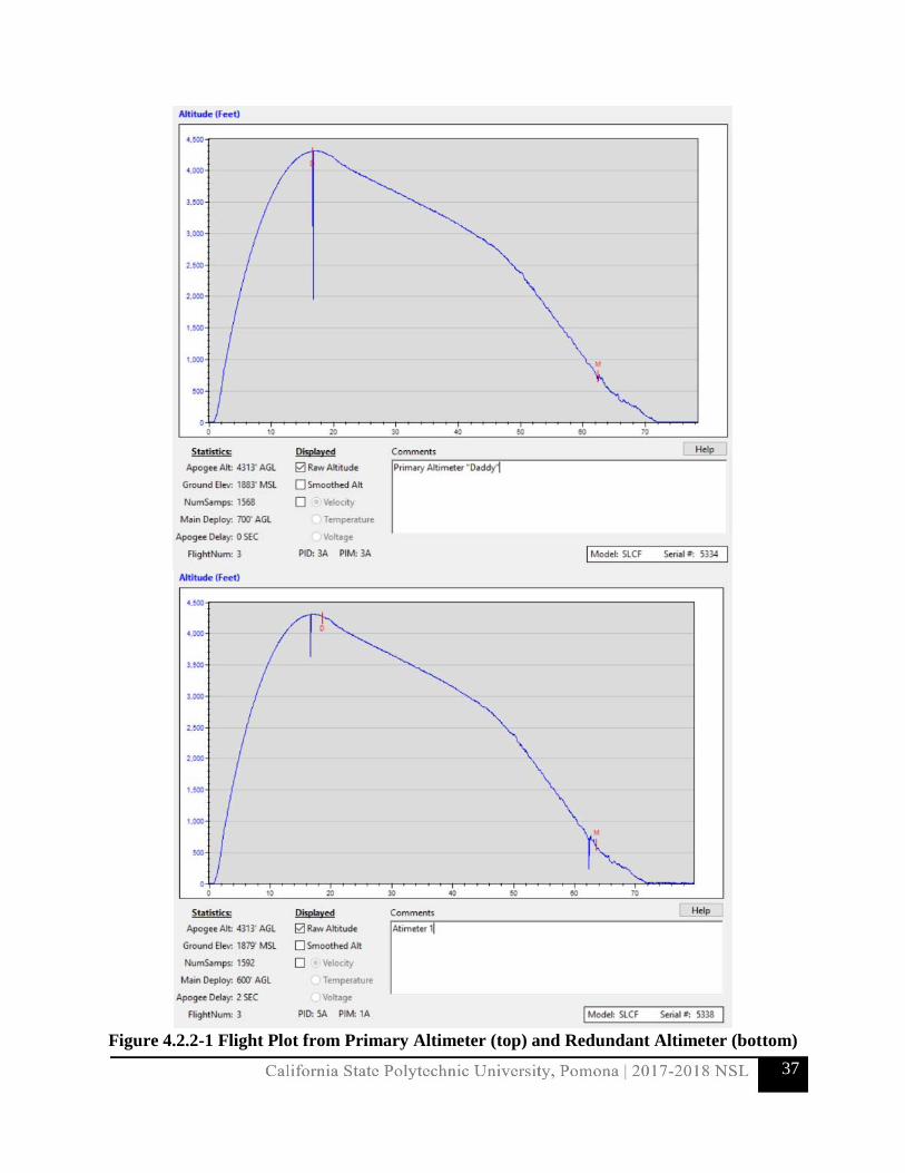
4.2.2 Apogee and Other Flight Data Both the primary and redundant altimeters were successful in recording data for the subscale flight. The raw data consists of a 4 by 1600 table recording the time, altitude, temperature, and battery voltage. Due to the extensive list of data acquired, a plot has been constructed to display the flight. Figure 4.2.2-1 is a graph of altitude vs. time generated on the PerfectFlite altimeter software (PerfectFlite DataCap). Both the primary and redundant altimeter plots are included.
37
Figure 4.2.2-1 Flight Plot from Primary Altimeter (top) and Redundant Altimeter (bottom)

38
The statistics regarding the flight are displayed underneath the plot. To prevent confusion at the launch site, each of the altimeter beeping frequencies were altered. This allowed for one to be distinguishable from the other. The primary altimeter had a lower frequency beep while the redundant altimeter had a higher pitched beep. For this reason, the primary altimeter was nicknamed the “daddy” and the redundant was nicknamed the “baby.” The primary altimeter deployed the drogue at apogee and the main at 700 ft. The redundant altimeter deployed the drogue at apogee + 2 seconds and the main at 600 ft. Both altimeters recorded an apogee of 4,313 ft. at around 18 seconds. The ejection charge ignitions can be seen on the plots via the pronounced spikes in the data. Drogue deployment was successful and was verified visually and on the data; the launch vehicle’s descent velocity slowed down dramatically. The main parachute ejected, but was partially deployed. Due to a minor error, the deployment bag was not attached appropriately, which prevented the full main deployment. The error was noted and documented to ensure it would not be repeated during full-scale test launches. Fortunately, the launch vehicle descended slowly enough to prevent damage during landing. The launch vehicle landed with damage to its fins, which was intended, as the reattach-able fin system is a key design feature. The fins were easily swapped out; thus, the subscale was successfully recovered and in reusable condition.
4.2.3 Scaling Factors The scaling factor for the subscale version of the launch vehicle is the comparison of characteristics on the subscale version relative to the full-scale launch vehicle. To determine the scaling factor, the subscale model goals were taken into careful consideration to prove the design integrity of the full-scale and to consider any manufacturing restrictions that could prove detrimental to the full-scale project plan. The goal of the subscale launch was to demonstrate that certain characteristics and components of the full-scale version will perform well in-flight conditions. To meet this goal, the subscale model would have to be large enough to accommodate various electronic components intended to be used in the full-scale launch vehicle, have a similar static margin to simulate flight characteristics, and contain a scaled down version of the recovery system to be used in the full scale. The greatest constraint was the availability of the body tube sizes due to the pre-manufactured state of the Blue Tube material. With all considerations taken, the scaling factor was decided to be 0.5 or a half-scale of the full-scale launch vehicle. This factor governs mainly the size of the launch vehicle, including the diameter, length, and mass of the launch vehicle (listed in Table 4.2.3-1). However, these were not necessarily critical values pursued for the subscale model.

39
Table 4.2.3-1: Subscale Size Scaling Factors
Launch Vehicle Characteristics Full-Scale Sub-Scale Scaling Factor (Sub-Scale/Full-Scale)
Body Tube Diameter (in.) 6.0 3.0 0.500
Overall Length (in.) 101 58 0.574
Overall Mass (lbs.) 43.7 7.84 0.178
As stated previously, the critical values pursued were those that would achieve the goal for the subscale. The first part of that goal was to use various electronics that would be used in the full-scale version, which is achieved by the diameter selection of the body tube. With the three-inch diameter body tube, analysis of the observation electronics was conducted, as well as the altimeter and recovery system, to be used in the full-scale launch vehicle. To achieve a similar static margin to the full-scale launch vehicle, an adjustment to the fin size was made. Once the subscale was in its final stage of completion, the data was simulated in the OpenRocket model, which returned a static margin of 2.59. This margin is only 2% of the expected full-scale static margin and should be close enough to provide similar flight characteristics to the full-scale vehicle, given that they have similar geometries. The last goal for the subscale was to test the recovery system, which was achieved by using the same layout for the parachutes and recovery system as is to be used in the full-scale. With a successful recovery of the subscale in reusable condition, the design integrity demonstrates that the layout and recovery system will be safe for use on the full-scale vehicle.
4.2.4 Launch Day Conditions and Simulation The conditions at the launch site at the time of launch were intermittent clouds, winds averaging 16 mph, and temperature of 59 degrees Fahrenheit. These values were used as inputs for an OpenRocket simulation along with the final configuration model of the subscale launch vehicle to obtain performance predictions of the subscale flight. The main purposes of the subscale vehicle have been previously stated, but some valuable data was obtained by comparing the subscale flight results with the predicted values from the simulations. With an altimeter and camera on-board, the data was limited to the apogee altitude. From the simulation, the software provided an apogee altitude of 4,602 ft. This value was then compared to the results collected from the subscale flight. 4.2.5 Subscale Flight Analysis
4.2.5.1 Predicted vs. Actual Flight Data and Error Calculation A computer program was created in MATLAB to predict the altitude of the subscale model at various times. To accomplish this, a drag coefficient of 0.49 was selected. This drag coefficient

40
was obtained from OpenRocket simulations. The rocket was assumed to have a constant mass throughout its flight, and the thrust used was calculated by taking the average of the average thrust and maximum thrust of the motor used. The subscale model contained two altimeters, which gave an apogee of 4313 feet. This was significantly different than the apogee given by the MATLAB program of 4669 feet, and the apogee given by OpenRocket of 4602 feet. Even though the difference between both values is large, the MATLAB program can more accurately predict the altitude of the subscale model as the value of the drag coefficient approaches its actual value. Another MATLAB program was created to calculate the drag coefficient using the data provided by the altimeter. Since two altimeters were used, each set of data was used to determine a drag coefficient for the subscale model. The values that were determined by the program for the drag coefficient were 0.43 and 0.64. When a drag coefficient of 0.64 was used, the MATLAB program was able to predict the altitude of the subscale model with a small amount of error. Figures 4.2.5.1-1 and 4.2.5.1-1 show the actual and predicted altitudes of the subscale model.
Figure 4.2.5.1-1 Predicted and Actual Altitude vs. Time using a Cd = 0.49

41
Figure 4.2.5.1-2 Predicted and Actual Altitude vs. Time using a Cd = 0.64
The apogee given by the MATLAB program when a drag coefficient of 0.64 was used was 4249 feet. When using the drag coefficient of 0.49 provided by OpenRocket, there was an error of 8%. When using the drag coefficient determined using the altimeter data, there was an error of 2%. The error associated with the OpenRocket simulation was 6.3%. This demonstrates that the MATLAB program can accurately predict the altitude of the full scale model using a drag coefficient provided by OpenRocket, and with very little error if the actual drag coefficient is used. Also, this demonstrates that OpenRocket simulations can predict the apogee of the full scale model accurately. The error produced is difficult to minimize since measuring an actual drag coefficient and reproducing the flight conditions of the subscale model in the program is difficult. This will most likely contribute to error in the predicted flight data of the full scale model.
4.2.5.2 Drag Coefficient Estimation Using a MATLAB program, the drag coefficient of the subscale model was calculated. Even though each altimeter provided data that produced two different drag coefficients, one was selected as the most accurate. The drag coefficients are obtained from OpenRocket to make flight

42
predictions. The errors associated with the subscale and full scale models are shown in Table 4.2.5.2-1 below.
Table 4.2.5.2-1 Cd and Error for Subscale and Full Scale Models
Subscale Model Full Scale Model
OpenRocket 0.49 0.45
MATLAB 0.64 0.59
Error 30.6% 30.6%
The drag coefficient of 0.64 for the subscale model was selected since it allowed the MATLAB program to accurately predict its altitude. The error associated with the OpenRocket drag coefficient and the drag coefficient determined with MATLAB and experimental data was 30.6%. Since the program was able to accurately predict the altitude of the subscale model using the calculated drag coefficient, it is estimated that the error associated with the drag coefficient of the full scale model is the same. Therefore, the drag coefficient of the full scale model is estimated to be 0.59.
4.2.6 Subscale Flight Data Impact The data acquired from the subscale model will allow the team to make more accurate predictions about the flight data of the full scale model. Two altimeters were placed inside the subscale model, and they were used to make two MATLAB programs. One program is used to predict the altitude of the full scale model, the other is used to determine the drag coefficient using data from the altimeters. The data from the altimeters on the subscale model allowed the team to calculate the accuracy of the drag coefficients provided by OpenRocket, and to estimate the drag coefficient of the full scale model using this information. Figures 4.2.6-1 and 4.2.6-1 show the MATLAB programs used to calculate the altitude and drag coefficient of the full scale model.

43
Figure 4.2.6-1 MATLAB Program to Calculate Altitude

44
Figure 4.2.6-2 MATLAB Program to Calculate Drag Coefficient
4.3 Recovery Subsystem
4.3.1 Final Recovery Design and Justification
The recovery subsystem was designed using a dual parachute deployment to satisfy Requirement 2.1. At apogee, the recovery bay altimeters will trigger the fore ejection charges, upon which the drogue parachute will be released. After the release and inflation of the drogue parachute, the rocket will coast down until a 600 ft altitude, upon which the main parachute bay altimeter will trigger aft ejection charges and the main parachute will be released. The landing velocity of the parachute has been found to be roughly 14 feet per second, satisfying the kinetic energy requirement. These calculations will be explained further in the kinetic energy section 4.4.7. A general mission trajectory and deployment sequence can be seen in Figure 4.3.1-1.

45
Figure 4.3.1-1: Parachute Trajectory and Deployment Sequence
The recovery events and their corresponding altitudes are described in Table 4.3.1-1:
Table 4.3.1-1 Recovery Subsystem Events
Event Altitude (ft.) Description
1 ~5,280 Apogee
Fore ejection charges fire, nose cone ejects, and drogue parachute is released.
2 600 Aft ejection charges fire and main parachute is released.
3 0 Touchdown
Rocket has landed safely, rover has been released, rocket and payload ready for retrieval
4.3.2 Parachute Design
Design and selection of the main parachute was based off Requirement 2.3’s maximum landing kinetic energy and NAR HPR Safety Code allowable drift distance. The chosen design for the

46
main parachute was a toroidal shape. This design was ultimately chosen over the other candidates because of its high coefficient of drag, which allowed for a more compact parachute to be needed to effectively reduce the descent rate of the rocket. The team ultimately decided to purchase a toroidal shaped parachute from Fruity Chutes manufactured from 1.1 oz. Mil-spec nylon. After subscale testing, the manufacturers advertised drag coefficient of 2.2 was found to hold true, thus Fruity Chute’s 120-inch Iris Ultra Standard parachute was chosen as the final design. This parachute model has an effective area of 80 square feet. The dimensions of the main parachute can be seen in Figure 4.3.2.1. Because of the main parachute’s toroidal design, there will be two sets of suspension lines about the inner and outer circumferences of the parachute that will be manufactured. These suspension lines will be constructed using nylon paracord rated to 550 lbs. and will be secured to a ¼” Kevlar bridle by zip ties and shrink wrap. The Kevlar shrink bridle is attached to a harness using both a quick link and a swivel. A delay ring is being utilized to prevent tear out of the bulkhead securing the parachute to the rocket by slowing the inflation time of the parachute via the brief restriction of suspension line motion. This configuration is illustrated below in Figure 4.3.2-2. The main parachute will be attached to two U-bolts located on the payload bay and nose cone using ¼” Kevlar shock cord rated at 2200 lbs.
Figure 4.3.2.-1: Main Parachute Toroidal Shape and Dimensions

47
Figure 4.3.2-2: Main Parachute Schematic
The drogue parachute will be fabricated by the team using 1.1 Ripstop nylon in a cruciform design. The cruciform shape was chosen due to its high stability during descent, which will keep the rocket within the required landing radius. Moreover, the cruciform shape minimizes packing volume and weight. From analysis, the required dimensions of the drogue are a gore length of 3 feet and a surface area of 4 square feet, and the drag coefficient of the manufactured drogue parachute is 0.6. An illustration of the drogue parachute can be seen in Figure 4.3.2-3 can be seen below. Suspension lines will be constructed from nylon paracord rated to 550 pounds, each with a length of 4 feet. The drogue’s suspension lines meet at a Kevlar bridle attached to a 500 lbs. rated steel swivel, after which a quarter inch 1000 lbs. rated quick link secures the drogue to a harness. This configuration can be seen in Figure 4.3.2-4 below. A quarter-inch shock cord rated at 2200 lbs. attaches the parachute quick link to a U-bolt above the motor bay and a U-bolt below the recovery bay.

48
Figure 4.3.2-3: Drogue Parachute Dimensions
Figure 4.3.2-4: Drogue Parachute Schematic

49
4.3.3 Harness Design The main and drogue parachute will both be connected by a shock cord measuring 30 ft. each. The shock cord that will be utilized will be 1/4 in. Kevlar rated at 2200 lbs. load. The quick links for the main will be 3/8th in. steel rated at 2100 lbs., and the drogue’s quick link will be 1/4th in. steel rated at 1000 lbs. The main parachute harness will mount to the avionics bay and the payload bay through use of a U-bolt attached to the end of each bay. The key requirement of the harness is to ensure that none of the bays collide with each other during deployment of the parachute. The harness will be split at different lengths to guarantee the safety of each component, as well as to ensure that no damage will be brought to the rocket. The main parachute will be 20 ft. from the avionics bay and 10 ft. from the payload bay when deployed. The drogue parachute harness will mount to the avionics bay and the motor bay, again using a U-bolt to secure to each bay. The drogue parachute will be 20 ft. from the avionics bay and 10 ft. from the motor bay when deployed. The dimensions of the harness design are shown in the figure below Figure 4.3.3-1.
Figure 4.3.3-1: Harness Design Overview

50
4.3.4 Attachment Hardware Design The hardware design of the recovery avionics bay is still consistent with what was reported in the PDR. This bay will have a total length of 12 inches, giving the altimeters, batteries, and wires enough space to be rearranged, if need be. The components of the bay include two PerfectFlite StratoLoggerCF altimeters, Eggfinder GPS, and a Trackimo GPS. They will run on 9 volt batteries. The altimeters will be mounted using the mounting hardware kit sold by PerfectFlite. Batteries will be fixed using 3 zip ties. A harness will be created for the Trackimo to fix it into the avionics sled. Lastly, the Eggfinder will be mounted using screws and nuts. The avionics sled is constructed of a 6 in by 10.5 in piece of plywood, which will then be secured in place by two ¾ in. bulkheads. Each bulkhead will have a #516-5/16” x 1-3/8” x 3-3/4” U-bolt attached at each end. Throughout the bay there will two threaded rods that will run through the inside of the recovery bay, and each bulkhead will be secured with hex nuts and steel washers at each end. The front and back view of the avionics hardware design can be seen below in Figure 4.3.4-1.
Figure 4.3.4-1: Front and Back view of the Avionics Hardware Design (simplified drawing) The altimeters and their power supplies will be placed on the front side of the sled. The batteries will be tied down securely to prevent any motion. This will prevent unwanted power loss during

51
flight. The altimeters will be easily accessible to allow for the replacement of E-matches. An example of the layout of the avionics sled can be seen in Figure 4.3.4-2.
Figure 4.3.4-2 Avionics Sled of Subscale Model
While the sled shown in the figure is from the subscale launch vehicle, the general layout will remain the same. The full-scale avionics sled will have more than twice the surface area to accommodate the altimeters; space will not be an issue for the avionics. The GPS units are placed on the back side. The Eggfinder GPS will be placed towards the top with its battery placed directly underneath. The Trackimo GPS can be placed anywhere because it does not require an external battery. With the compact size of the avionics components, the team has

52
much flexibility in the placement of the components since the full-scale launch vehicle body is twice the diameter of the subscale. 4.3.5 Electrical Components Design: GPS
Figure 4.3.5-1: Eggfinder RX (Top) and TX (Bottom)
The primary tracking device will be the Eggfinder GPS, shown in Figure 4.3.5-1, will. It will be housed in the Recovery Bay component of the launch vehicle and will be powered using a 9V alkaline battery. The Eggfinder TX transmits at 900 MHz utilizing an attached “stick” antenna. The RX receiver module will plug into the ground command module computer. In this configuration, the system can communicate up to 8,000 feet. By means of the uplink between the RX and TX modules, the flight path data will be plotted using Google Earth or other KML file reading software.
Table 4.3.5-1: Eggfinder Specifications
Battery 9 Volt
Accuracy 8.2 ft
Transmitter Frequency 900 MHz
Weight 0.706 oz.
Dimensions 3.5 in x .9 in x .4 in
Range 8,000 ft

53
Figure 4.3.5-2 Trackimo GPS unit
The Redundant tracking device will be the Trackimo Commercial GPS unit, shown in Figure 4.3.5-2. It will be housed in the recovery bay along with the Eggfinder (If interference is an issue between the two GPS systems, it will be relocated). The Trackimo has its own internal, rechargeable battery. The Trackimo operates on the quad band GSM frequency (850/900/1800/1900 MHz). The unit can be tracked easily using the Trackimo website or application for mobile phones. It is live mapping software that can refresh every minute.
Table 4.3.5-2: Trackimo Specifications
Battery Internal Rechargeable LiPo
Accuracy ~50 feet
Transmitter Frequency
Quad Band (850/900/1800/1900 MHz)
Weight 1.4 oz.
Dimensions 1.8 x 1.6 x 0.7 inches
Range No limitations on range as long as cellular service or internet connection is present

54
4.3.5.1 Drawings and Sketches
Figure 4.3.5.1-1: Eggfinder Technical Drawing
Figure 4.3.5.1-2 Trackimo Technical Drawing

55
4.3.5.2 Block Diagrams
Figure 4.3.5.2-1: Eggfinder GPS Block Diagram The block diagram displayed above in Figure 4.3.5.2-1 shows the flow of information through the GPS system. Via this pathway, the Ground Control System will have uninterrupted data on the flight vehicle’s location. This relies on constant communication between the GPS array, GPS, TX module, and RX module which will be plugged into the Ground Control computer. The block diagram for the Trackimo GPS unit is shown in Figure 4.3.5.2-2.
Figure 4.3.5.2-2 Trackimo GPS Block Diagram

56
It can be noted that the Trackimo GPS system is much more flexible than the Eggfinder. It does not require a ground station and the unit can be tracked from virtually anywhere as long as internet connectivity can be attained. 4.3.5.3 Electrical Schematics The reverse side of the sled will contain the GPS units. Figure 4.3.5.3-1 below exhibits the electrical schematics for the GPS units. There are two GPS units: the Eggfinder GPS transmitter, shown on the right of Figure 4.3.5.3-1, and the Trackimo, shown on the left. The Trackimo is a unit that does not require an external battery. However, the Eggfinder requires a power source which will be a 9 volt battery. The 9 volt can supply enough power for the Eggfinder to run for more than one hour
Figure 4.3.5.3-1: GPS Electrical Schematics
4.3.6 Electrical Components Design: Altimeters Two PerfectFlite StratoLoggerCF Altimeters, seen in Figure 4.3.6-1, will be used for deployment of both the drogue and main parachutes. Utilizing pressure and temperature sensors, the StratoLogger extrapolates altitude. The main parachute deployment may be altered at 1 foot increments between 100 and 9,999 feet. Using a USB dongle, flight data may be downloaded to a computer and plotted using the PerfectFlite DataCap software. Additionally, this software allows for the programming of deployment altitudes.

57
Figure 4.3.6-1: PerfectFlite StratoLoggerCF
Table 4.3.6-1: StratoLogger CF Specifications
Main Chute Deployment Capabilities
Range of 100 feet - 9,999 feet at 1 foot increments with 9 Presets for quick selection
Drogue Chute Deployment Capabilities
At Apogee
Flight Data Storage 16 flights at 18 minutes each
Dimensions 2.0 in x .84 in x 0.5 in
Weight 0.380 oz.
Output Current 5 Amps
Data Collection Altitude, Temperature, Battery Voltage
4.3.6.1 Drawings and Sketches
Figure 4.3.6.1-1: StratoLoggerCF Technical Drawing
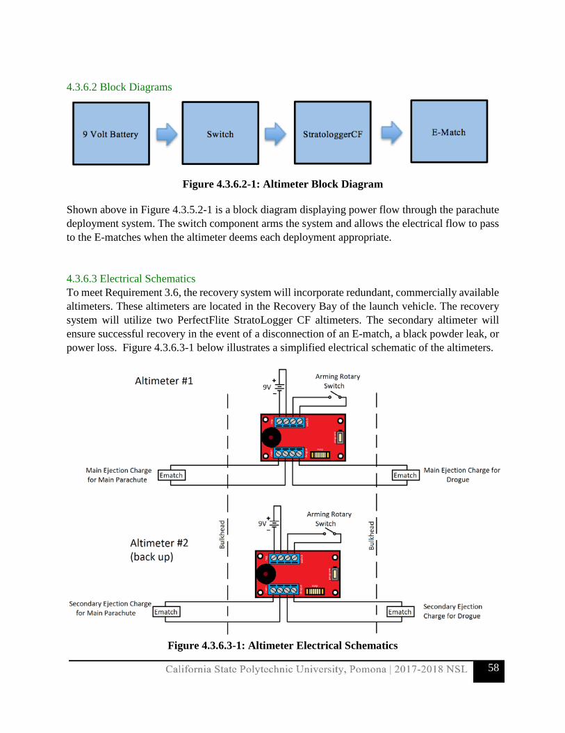
58
4.3.6.2 Block Diagrams
Figure 4.3.6.2-1: Altimeter Block Diagram
Shown above in Figure 4.3.5.2-1 is a block diagram displaying power flow through the parachute deployment system. The switch component arms the system and allows the electrical flow to pass to the E-matches when the altimeter deems each deployment appropriate.
4.3.6.3 Electrical Schematics To meet Requirement 3.6, the recovery system will incorporate redundant, commercially available altimeters. These altimeters are located in the Recovery Bay of the launch vehicle. The recovery system will utilize two PerfectFlite StratoLogger CF altimeters. The secondary altimeter will ensure successful recovery in the event of a disconnection of an E-match, a black powder leak, or power loss. Figure 4.3.6.3-1 below illustrates a simplified electrical schematic of the altimeters.
Figure 4.3.6.3-1: Altimeter Electrical Schematics

59
Each altimeter is connected to two E-matches: one for the main and one for the drogue. The E-matches ignite the black powder charges used for the ejection system. Each altimeter will have a 9V battery as its own power supply, as well as a dedicated arming switch. The 9 volt batteries provide sufficient power in the event the rocket has to sit on the launch rail for above an hour before launching. To prevent premature ejection, the arming switches will be utilized to arm the altimeters once the rocket is ready on the launch rail. 4.3.7 Electrical Component Redundancy: GPS and Altimeters Both the Altimeters and GPS systems contain redundancy. There are two GPS units being utilized for the launch vehicle: Eggfinder GPS and Trackimo. The Eggfinder GPS will be the primary GPS unit. The Eggfinder utilizes a 900 MHz band to send and receive data. The transmitter will be placed in the launch vehicle, while the receiver will be connected to a ground station. The range between the transmitter and receiver cannot exceed two miles, or a link will not be able to be established. The Trackimo GPS will be used as the redundant unit and will utilize the GSM and GPS network to share positioning coordinates. The Trackimo can be tracked very easily using the Trackimo website on a computer, or even on a phone using the Trackimo phone application.
4.3.8 Operating Frequency of Locating Trackers
Table 4.3.8-1: Operating Frequency of Trackers
GPS Unit Operating Frequency Receiver
Eggfinder 900 MHz RX unit on Ground Station
Trackimo Quadband GSM (850/900/1800/1900 MHz) Ground Station or Mobile Phone
4.4 Mission Performance Predictions
4.4.1 Flight Profile Simulations
OpenRocket was used to simulate and analyze the flight profiles to verify that all requirements were met by the current design. Trajectories were analyzed at wind speeds of 0, 5, 10, 15, and 20 mph. Table 4.4.1-1 to Table 4.4.1-5 display the results of the varying simulations, in ascending order of velocity.

60
Table 4.4.1-1: Flight Trajectory Results at 0 mph Velocity Off Rod
(ft/s) Apogee
(ft)
Optimum Delay
(s)
Max Velocity
(ft/s)
Max Acceleration
(ft/s2)
Time to Apogee
(s)
Total Flight Time
(s)
Ground Hit
Velocity (ft/s)
60.7 5507 18.7 664 251 18.7 152 20.8
Table 4.4.1-2: Flight Trajectory Results at 5 mph Velocity Off Rod
(ft/s) Apogee
(ft)
Optimum Delay
(s)
Max Velocity
(ft/s)
Max Acceleration
(ft/s2)
Time to Apogee
(s)
Total Flight Time
(s)
Ground Hit
Velocity (ft/s)
60.7 5491 15.5 664 251 18.7 152 20.8
Table 4.4.1-3: Flight Trajectory Results at 10 mph Velocity Off Rod
(ft/s) Apogee
(ft)
Optimum Delay
(s)
Max Velocity
(ft/s)
Max Acceleration
(ft/s2)
Time to Apogee
(s)
Total Flight Time
(s)
Ground Hit
Velocity (ft/s)
60.7 5449 15.5 664 251 18.6 151 20.9
Table 4.4.1-4: Flight Trajectory Results at 15 mph Velocity Off Rod
(ft/s) Apogee
(ft)
Optimum Delay
(s)
Max Velocity
(ft/s)
Max Acceleration
(ft/s2)
Time to Apogee
(s)
Total Flight Time
(s)
Ground Hit
Velocity (ft/s)
60.7 5394 15.5 662 252 18.5 149 20.8
Table 4.6.2-5: Flight Trajectory Results at 20 mph Velocity Off Rod
(ft/s) Apogee
(ft)
Optimum Delay
(s)
Max Velocity
(ft/s)
Max Acceleration
(ft/s2)
Time to Apogee
(s)
Total Flight Time
(s)
Ground Hit
Velocity (ft/s)
60.7 5331 15.5 661 252 18.5 149 20.5 Using the above date, it was determined that the maximum altitude for each case was slightly above Requirement 2.1’s altitude of 5280 ft. Though these results exceed the requirement, they can still be considered valid since OpenRocket simulations assume ideal flights, and an actual launch will not be able to be performed in these perfect conditions. Since the launch rail was simulated at the minimum 10-foot length, the exit rail velocity was calculated at 60.7 ft/s, exceeding the requirement of obtaining a launch vehicle exit rail velocity greater than 52 ft/s. Additionally, it can be noted that wind velocity was not a great impact on the flight profile due to

61
the launch vehicle’s high stability margin of 2.62 cal. One of the only concerns of simulation at this moment is a high vertical acceleration on flight, seen at launch. 4.4.2 Simulated Motor Thrust Curve The Aerotech L1420 has a motor thrust curve that is capable of accelerating the launch vehicle to the target altitude of 5280 ft. As shown below in Figure 4.4.2-1, there is an initial acceleration to a peak thrust Newtons. Afterwards, the motor experiences a gradual increase after 0.5 seconds, in order to achieve a maximum thrust of approximately 1625 Newtons in thrust. For the remaining two seconds, the motor gradually decreases to 1200 Newtons and tapers to 0 Newtons in the last quarter of a second to MECO. Table 4.4.2-1 further describes the Aerotech L1420 performance parameters.
Figure 4.4.2-1: Aerotech L1420 Thrust Curve
Table 4.4.2-1: Aerotech L1420 Performance Parameters
Propellant Weight 5.644 lb
Motor Weight 10.057 lb
Peak Thrust 407.803 lb
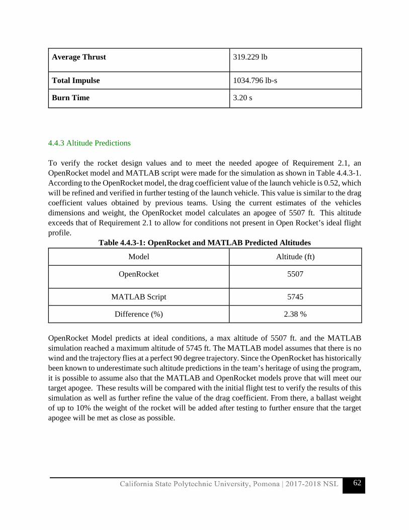
62
Average Thrust 319.229 lb
Total Impulse 1034.796 lb-s
Burn Time 3.20 s
4.4.3 Altitude Predictions To verify the rocket design values and to meet the needed apogee of Requirement 2.1, an OpenRocket model and MATLAB script were made for the simulation as shown in Table 4.4.3-1. According to the OpenRocket model, the drag coefficient value of the launch vehicle is 0.52, which will be refined and verified in further testing of the launch vehicle. This value is similar to the drag coefficient values obtained by previous teams. Using the current estimates of the vehicles dimensions and weight, the OpenRocket model calculates an apogee of 5507 ft. This altitude exceeds that of Requirement 2.1 to allow for conditions not present in Open Rocket’s ideal flight profile.
Table 4.4.3-1: OpenRocket and MATLAB Predicted Altitudes
Model Altitude (ft)
OpenRocket 5507
MATLAB Script 5745
Difference (%) 2.38 %
OpenRocket Model predicts at ideal conditions, a max altitude of 5507 ft. and the MATLAB simulation reached a maximum altitude of 5745 ft. The MATLAB model assumes that there is no wind and the trajectory flies at a perfect 90 degree trajectory. Since the OpenRocket has historically been known to underestimate such altitude predictions in the team’s heritage of using the program, it is possible to assume also that the MATLAB and OpenRocket models prove that will meet our target apogee. These results will be compared with the initial flight test to verify the results of this simulation as well as further refine the value of the drag coefficient. From there, a ballast weight of up to 10% the weight of the rocket will be added after testing to further ensure that the target apogee will be met as close as possible.

63
4.4.4 Center of Pressure and Gravity Center of Gravity: Two methods were used in order to obtain center of gravity. The first method calculates the center of gravity with the help of OpenRocket, which also aids with real-time center of gravity and center of pressure analysis. The emphasis on the distribution of weight, proper location, and total length is important to ensure the center of gravity is ahead of the center of pressure. As previously mentioned, this presented a slight change in CG than what OpenRocket had simulated for subscale model, but the change was not significant to roll out OpenRocket values, but hand calculations will also be done to verify the results. Derived from the team’s OpenRocket model the center of gravity taken from the tip of the nose cone was reported to be 62.695 inches, as denoted by Figure 4.4.4-1 shown below. To verify this method, the center of gravity proposed to us by OpenRocket were deduced by hand calculations and confirmed with Excel.
Figure 4.4.4-1: Visual diagram of the team’s leading model’s center of gravity
For every section of the launch vehicle, there is a given detailed estimated weight, denoted as wi, which was calculated by weighing out each sub-component and summing them to find an overall weight. The centroid, denoted as xi, was then estimated using the longitudinal axis of the leading launch vehicle. By multiplying the centroid of each component's axis by its respective weight, a moment is produced. The summation of each component's moment is then divided by the total weight of the launch vehicle. This equation provides for us equation 4.4.4-1, as shown below.
• XC.G. = Dm1Wm1+Dm2Wm2+Dm3Wm3Wm1+Wm2+Wm3
(4.4.4-1)
Equation 4.4.4-1: Center of Gravity
Where: Wm() denotes the weight of each module Dm() denotes the distance between each module to the nose tip, an XC.G. denotes the location of center of gravity from the nose tip

64
In application, the team divided the rocket into three separate modules in order to calculate the center of gravity. The figure shown below depicts each respective module.
Figure 4.4.4-2: Visual representation of Module 1, Module 2, Module 3 of the team’s Leading Model
Center of Pressure: Our team will assume that all masses are centered for simplicity until further notice and confirmation upon building our full-scale model. By inputting the values produced from the team’s leading model, we can deduce that the center of gravity is 63.52 inches with only a 1.31% difference. These values verify the methods utilized to produce these values.
Center of Gravity (OpenRocket) 62.695 inches
Center of Gravity (Hand Calculations) 63.52 inches
Percent Difference 1.31%
Table 4.4.4-1: A formatted table indication the OpenRocket-calculated and hand-calculated values, along with the respective percent difference.
The center of pressure of the team’s launch vehicle is the point at which air pressure forces are concentrated. In reference to the team’s launch vehicle, careful consideration of the fin design and dimensions, along with the geometry of the aerodynamic sections were considered in order to ensure that the center of pressure fails under the desired stability. The figure below depicts the center of pressure denoted by the red dot shown as such:
Figure 4.4.4-3: Visual diagram of the Center of Pressure for the team’s leading design.

65
The James Barrowman equations were used to calculate center of pressure. To execute Barrowman’s equation, sectionalized analysis of individual components (the nose cone, separate body sections, and fins) were utilized, along with the theory of moments in order to derive the total normal force of the launch vehicle. The overall center of pressure for the launch vehicle is calculated by multiplying the coefficient of pressure by the respective components center of pressure. In application of the Barrowman’s equations to our launch vehicle, the team must fly with small angles of attack in the subsonic regions to coincide with the equation used to calculate center of pressure. First, denoting the tip of the nose cone as the origin where x equal zero, begin to increase the values of x as they move from the nose tip towards the tail end of the launch vehicle. The initial calculation for the tam’s center of pressure is for the elliptical nose cone. This is determined by computing the volume enclosed by its surface and divide the volume by the cross-sectional area of the elliptical nose cone diameter; this resultant value will give the length equal to the distance from the origin of the component’s relative center of pressure. Because the team’s leading design has an elliptical geometry, the location for center of pressure can be approximated to a third of the overall nose cone length. From this information, the center of pressure location was calculated to be 78.014 inches from the tip of the nose cone. In order to calculate the center of pressure for each fin, the following procedure is used: find the coefficient of normal force at a single fin, expressed below by equation 2 of 4.4.4:
• 𝑋𝑋𝐶𝐶.𝑃𝑃. = (𝐶𝐶𝑁𝑁)𝑛𝑛𝑋𝑋𝑛𝑛+(𝐶𝐶𝑁𝑁)𝑓𝑓𝑋𝑋𝑓𝑓(𝐶𝐶𝑁𝑁)𝑛𝑛+(𝐶𝐶𝑁𝑁)𝑓𝑓
(4.4.4-2)
Where: (𝐶𝐶𝑁𝑁)𝑛𝑛 denotes the nose cone normal force (𝐶𝐶𝑁𝑁)𝑓𝑓 denotes the fin normal force 𝑋𝑋𝑛𝑛 denotes the distance between the nose tip and nose center of pressure location 𝑋𝑋𝑓𝑓 denotes the distance between the nose tip and fin center of pressure location Based on the design of the nose cone, (𝐶𝐶𝑁𝑁)𝑛𝑛 and 𝑋𝑋𝑛𝑛 are given by:
• (𝐶𝐶𝑁𝑁)𝑛𝑛 = 2
• 𝑋𝑋𝑛𝑛 = (. 466)𝐿𝐿𝑛𝑛
Where: 𝐿𝐿𝑛𝑛 denotes the length of the nose cone Additionally, (𝐶𝐶𝑁𝑁)𝑓𝑓 and 𝑋𝑋𝑓𝑓 can be found using the following equations:

66
• (𝐶𝐶𝑁𝑁)𝑓𝑓 =4𝑛𝑛(𝑆𝑆𝐷𝐷)2
1+�1+( 2𝐿𝐿𝐴𝐴+𝐵𝐵)2
(4.4.4-3)
• 𝑋𝑋𝑓𝑓 = 𝑋𝑋𝑓𝑓 + ∆𝑋𝑋𝑓𝑓 (4.4.4-4)
• ∆𝑋𝑋𝑓𝑓 = 𝑀𝑀(𝐴𝐴+2𝐵𝐵)
3(𝐴𝐴+𝐵𝐵)+ 1
6(𝐹𝐹 + 𝜏𝜏 − 𝐴𝐴𝐵𝐵
𝐴𝐴−𝐵𝐵) (4.4.4-5)
Where:
S denotes the fin semi-span n denotes the number of fins A denotes the fin root chord B denotes the fin tip chord length L denotes the length of the fin’s half chord D denotes the rocket’s diameter M denotes the projected length from the front edge fin root to front edge of fin tip
𝑋𝑋𝑓𝑓 denotes the distance from nose tip to front edge of fin root The center of pressure was located to be 77.32 inches from the origin. In comparison to the OpenRocket which gives the center of pressure to be 78.014 inches, the percent difference between the two points is .89%. The table below indicates these confirmed values.
Center of Pressure (OpenRocket) 78.014 Inches
Center of Pressure (Hand Calculation) 77.32 Inches
Percent Difference .89%
Table 4.4.4-2: Summary for Center of Pressure results 4.4.5 Stability Margin Stability margin, defined as the distance between the Center of Pressure and Center of Gravity, is measured in calibers. To put it into perspective, one caliber is equivalent to the maximum body diameter of the launch vehicle. Going further into this, the stability of the rocket is to ensure that the launch vehicle will stay in flight without tumbling, tilting, or spinning in an undesired flight path. In amateur rocketry, an approximate 10-inch length-to-diameter ratio would assume a stability margin of 1 to 2 calibers. However, because our rocket will be exceeding that approximate 10-inch length-to-diameter ratio, a larger stability margin is desirable (closer to the 2.0 caliber margin). Since the launch vehicle is considerably long compared to its radius, a large moment arm between the CP and CG locations is necessary to stabilize the launch vehicle, and prevent body

67
lift forces from weather-cocking, which is also why the stability range is higher for our launch vehicle. From OpenRocket, we can derive the center of gravity location of the team’s leading design to be 62.695 inches from the nose tip, as the center of pressure location is 78.014 inches also from the nose tip, with a resultant distance of 15.319 inches between the two locations. By dividing the distance between the center of gravity and center of pressure 15.319 inches by the leading design’s outer diameter 6.16 inches, produces a static margin of 2.48 calibers, as denoted by the red dot in Figure 4.4.5-1 shown below.
Figure 4.4.5-1: Center of Gravity and Center of Pressure locations indicating the difference
which is the stability margin In correspondence to what was previously stated, the larger stability margin is within the proposed range which the team deems as stable to fly. All changes to the weight of the vehicle will be closely monitored and constantly updated in OpenRocket model in order to ensure the team’s latest launch vehicle update and will ensure that the stability margin does not exceed 3 calibers. In reference to our sub-scale model, the team has adjusted the masses in correspondence to our full-scale model in order to ensure a reliable stability margin. Although there are slight variations in the sub-scale model to that of its full-scale model, the team concluded that there are no issues with stability or weather-cocking, even against harsh conditions.
Table 4.4.5-1: Representation of the OpenRocket values versus Hand Calculated values
Stability Margin (OpenRocket)
2.62 Calipers
Stability Margin (Hand Calculations)
2.25 Calipers
Percent Difference 14.5%
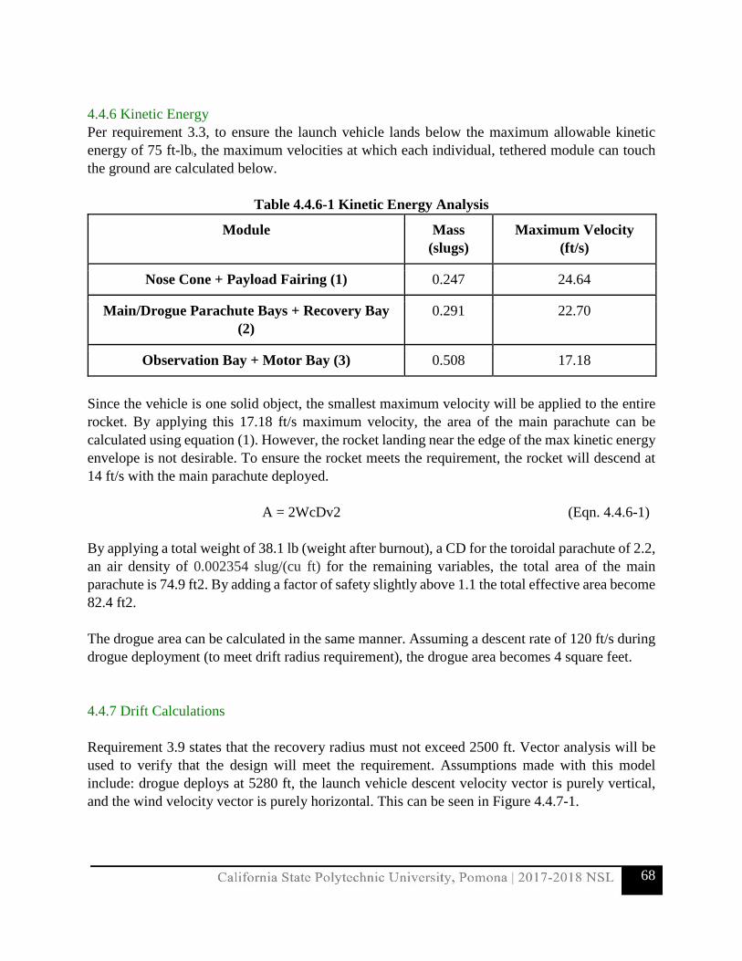
68
4.4.6 Kinetic Energy Per requirement 3.3, to ensure the launch vehicle lands below the maximum allowable kinetic energy of 75 ft-lbf, the maximum velocities at which each individual, tethered module can touch the ground are calculated below.
Table 4.4.6-1 Kinetic Energy Analysis
Module Mass (slugs)
Maximum Velocity (ft/s)
Nose Cone + Payload Fairing (1) 0.247 24.64
Main/Drogue Parachute Bays + Recovery Bay (2)
0.291 22.70
Observation Bay + Motor Bay (3) 0.508 17.18
Since the vehicle is one solid object, the smallest maximum velocity will be applied to the entire rocket. By applying this 17.18 ft/s maximum velocity, the area of the main parachute can be calculated using equation (1). However, the rocket landing near the edge of the max kinetic energy envelope is not desirable. To ensure the rocket meets the requirement, the rocket will descend at 14 ft/s with the main parachute deployed.
A = 2WcDv2 (Eqn. 4.4.6-1) By applying a total weight of 38.1 lb (weight after burnout), a CD for the toroidal parachute of 2.2, an air density of 0.002354 slug/(cu ft) for the remaining variables, the total area of the main parachute is 74.9 ft2. By adding a factor of safety slightly above 1.1 the total effective area become 82.4 ft2. The drogue area can be calculated in the same manner. Assuming a descent rate of 120 ft/s during drogue deployment (to meet drift radius requirement), the drogue area becomes 4 square feet. 4.4.7 Drift Calculations Requirement 3.9 states that the recovery radius must not exceed 2500 ft. Vector analysis will be used to verify that the design will meet the requirement. Assumptions made with this model include: drogue deploys at 5280 ft, the launch vehicle descent velocity vector is purely vertical, and the wind velocity vector is purely horizontal. This can be seen in Figure 4.4.7-1.

69
Figure 4.4.7-1 Vector Addition of Descent Velocity and Wind Velocity
The drift radius is dependent on how long the rocket stays in the air. There are two periods of interest when analyzing: the time period from apogee to main deployment and the time period from main deployment to touch down. The time from apogee to main deployment can be calculated with the following equation: Tapogee to main = Hapogee - Hmain deploymentVdrogue (Eqn. 4.4.7-1)
Where, Hapogee is the apogee altitude, Hmain deployment is the main deployment altitude, Vdrogue is the descent rate with the drogue chute deployed. The time from main deployment from touchdown can be calculated with the following equation:
Tmain to touchdown = Hmain deploymentVmain (Eqn. 4.4.7-2)
Where, Vmain is the descent velocity with the main parachute deployed. The drift distance can then be easily calculated by multiplying the horizontal wind velocity with the total time spent in air:
Drift radius = Vwind(Tapogee to main +Tmain to touchdown ) (Eqn. 4.4.7-3)
Table 4.4.7-2 Wind Velocity with Corresponding Drift Distances
Wind Velocity (mph) Drift Distance (ft)
0 0
5 624
10 1248

70
15 1873
20 2497
Assuming: Hapogee = 5280 ft Hmain deployment = 600 ft Vdrogue= 120 ft/s Vmain = 14 ft/s 5.0 Safety
5.1 Launch Concerns and Operation Procedures
5.1.1 Recovery Preparation PPE Required:
• Safety Glasses
1. Perform visual inspection of all electronics and wire connections. 2. Ensure handler and those in the vicinity are wearing safety glasses. 3. Ensuring powder charges are facing away from all personnel; connect main powder
charges to exterior terminals on the fore payload bay bulkhead. 4. Mount powder charges onto the payload bulkhead. 5. Ensure continuity and secure placement of powder charges. 6. Bolt bulkhead and main parachute bay onto the front of the payload bay. 7. Ensuring powder charges are facing away from all personnel; connect drogue powder
charges to exterior terminals on the forward recovery bay bulkhead. 8. Mount powder charges onto the front bulkhead. 9. Ensure continuity and secure placement of powder charges. 10. Connect altimeters to the terminal leads; ensure continuity. 11. Announce the intention to connect batteries and clear area of all unnecessary personnel. 12. Connect two (2) batteries. 13. Carefully slide electronics board into place. 14. Bolt bulkhead and drogue parachute pay onto the front recovery bay.
Concerns:
• If continuity is not present in powder charges or altimeters, parachutes may not deploy which results in loss of launch vehicle.

71
Black Powder Charge Preparation: PPE Required:
• Safety Glasses
1. Ensure handler and those in the vicinity are wearing safety glasses. Only the mentor will be allowed to handle preparation.
2. Insert he E-match into the modified shell. 3. Ensure seal at Insertion point. 4. Carefully pour the measured amount of black powder into the modified shell. 5. Pack the remaining space of the modified shell with “dog barf” wadding. 6. Seal the top of the modified shell with blue painter’s tape. 7. Place the prepared powder charge into the ammunition can until ready to mount.
Concerns:
• If the black powder amount is not enough, the parachute may fail to deploy which results in the loss of the launch vehicle.
• If ignited prematurely, the parachute may deploy too early or will damage the recovery system.
• If bulkhead is not plugged the corrosive gases may shorten the life of the electronics in the bulkhead.
• If bulkhead is not plugged pressure may bleed into the recovery bay which may cause the parachute to fail to deploy which will result in the loss of the launch vehicle.
Main Parachute and Drogue Parachute Preparation: No PPE Required
1. Perform visual inspection of nylon shock cords. 2. Perform visual inspection of Nomex Thermal Protection Blankets. 3. Perform visual inspection of connection points (quick links and eye bolts). 4. Perform visual inspection of the main and drogue parachutes. 5. Attach Nomex Thermal Protection Blankets to the parachute/shock cord connection point. 6. Fold the main parachute according to the proper folding procedure as deemed by Fruity
Chutes. 7. Wrap the folded parachute in Nomex Thermal Protection Blankets ensuring there is no
exposed parachute material. 8. Connect to the respective eye bolt on the recovery bay. 9. Insert into the respective parachute bay. 10. Set aside until ready to mount.

72
Concerns: • Shock cord harness gets tangled or zippers out of body tube. • Suspension lines tangle during deployment. • Parachute ignites during deployment. • If parachute not connected properly, parachute may fail which will result in loss of launch
vehicle.
5.1.2 Motor Preparation PPE Required:
• Safety Glasses • Gloves
1. Ensure the L2 certified Mentor and those in the vicinity are wearing safety glasses. 2. Ensure the motor casing has not been damaged or modified. 3. Unwrap the motor and place on an appropriate surface away from other flammable
materials. 4. Ensure all materials listed in the manual are present and not damaged. 5. Apply a thin film of silicon O-ring lubricant to the inside of the motor casing. 6. Apply a thin film of silicon O-ring lubricant to the outside of the motor. 7. With the protective nozzle cap on, insert the motor into the motor tube. 8. Apply lubricant to the threads of the aft closure. 9. Remove the nozzle cap and thread aft closure onto the case. Tighten until the motor is
properly seated. 10. Reinstall the nozzle cap onto the nozzle. 11. Wipe clean the motor casing ensuring there is no residue. 12. Insert the motor casing into the motor mount. 13. Attach retention ring. 14. Insert motor mount into the motor bay.
Safety Concerns:
• Foreign debris entering the propellant. • Keep the propellant and motor away from heat sources • Ensure nothing can ignite the propellant, by keeping wires away or shunted can prevent
ignition. 5.1.3 Setup on Launcher No PPE Required
1. Lower launch rail into the horizontal position.

73
2. Ensure no personnel are in the flight path of the launch vehicle, carefully slide the launch vehicle onto the launch rail.
3. Ensure the launch vehicle is properly seated on the launch rail. 4. Ensure the igniter is properly fed into the Ignition Insertion System.
Safety Concerns:
• Ensure nobody is in the trajectory of the launch vehicle when the launch rail is being lowered or while the launch vehicle is on the launch rail.
• Only the RSO should be nearby the launch vehicle when the igniter is inserted to the motor and is armed.
• Ensure everybody is in a safe area before the launch vehicle will be launched. 5.1.4 Ignition Installation PPE Required:
• Safety Glasses
1. Strip and split wires of the E-matches that interface to the altimeter’s screw down terminals. Do this a total of four times.
2. Ensure the altimeters and batteries are properly attached to the sled and switches are properly attached.
3. Feed the end of the stripped wires through the hole of the bulkheads, two for the main parachute and two for the drogue parachute.
4. Attach the respective wires to each altimeter and ensure they are attached by firmly tugging on the wires three to four times.
5. Power on the system and check for continuity. If there is no continuity repeat step four; if the problem continues replace E-match by following steps one through four.
6. Insert the sled into the recovery bay and close the bay with the bulkheads. 7. After the ejection charge has been poured into the well and the E-match is properly inserted,
plug the hole that the E-match wires are routed through so corrosive gases do not enter the recovery bay after deployment
Safety Concerns
• If the connections are not tested for continuity before launch, it is possible that the parachute will fail to deploy which will result in the loss of the launch vehicle.
• If connections are not attached firmly, the connections may not be able to withstand the conditions experienced during flight and the parachute may fail to deploy which will result in the loss of the launch vehicle.
• If bulkhead is not plugged the corrosive gases may shorten the life of the altimeters and pressure bleeding into the recovery bay may cause the parachute to fail to deploy, this will result in the loss of the launch vehicle.

74
5.1.5 Troubleshooting
Payload Experiment: DARIC and SPOC System Procedure:
1. Check all electrical connections 2. Test run software, ensure signal transmission and autonomous deployment of solar panels 3. Check all mechanical components are secure and functioning correctly 4. Ensure rover is securely placed in SPOC system
Concerns: 1. If batteries are not fully charged, rover will not have power 2. If SPOC system is functioning properly, Rover may not deploy correctly 3. If receiver is not receiving a signal, rover will not deploy 4. If the rover experiences unforeseen forces, this may cause malfunctions in the hardware
Motor Ignition: Procedure:
1. Immediately cease all procedures. Ensure that the arming switch is removed. 2. Team Lead and SO should be aware and shall replace motor igniter by mentor inspection. 3. Once inspection is complete, retreat from the launch pad and proceed with ignition.
Concerns:
1. The RSO should be the only one handling misfired igniters and motors. 2. A spark may occur when connecting clips to igniters. Clips should be checked for spark
before making contact with igniter. 3. If an igniter or motor misfires, allow at least one minute to pass before taking any action.
5.1.6 Post-Flight Inspection Procedure:
1. Do not stop visually tracking launch vehicle until cleared. Listen for sounds of deployment before retreating from covered ground.
2. Once sky is clear, assemble two groups of at least two team members to recover the launch vehicle.
3. The team mentor should accompany students during launch vehicle recovery. 4. Wait a minimum of sixty seconds before securing the launch vehicle. 5. Inspect the launch vehicle’s external components for any clear signs of damage. 6. Document the launch vehicle through inspection and photographs for the later assessment. 7. Download pictures, video, and scientific data and review altimeter data.

75
Concerns: 1. Ejection charges fail; thus, deployment fails, and launch vehicle descends ballistic. 2. Ensure team members stay off launch range until all clear is given from the RSO. 3. Ensure team members do not chase vehicle as it is descending. 4. Team members must stick in pairs in case of launch site environmental hazards as reviewed
by the SO prior to participating in launch procedures. 5. Ensure team members do not touch the launch vehicle until the team mentor has completed
inspection. 6. Ensure that team members properly document the landing site of the vehicle and its
components. This is critical when evaluating test plan success criteria.
5.2 Safety and Environment: Vehicle and Payload
The following sections updates the hazards presented in the project’s design and mitigations to minimize potential threats the team may face, be it as a direct result of their actions or caused by the environment and out of their control. More detailed systems, including the RIS, are discussed utilizing the Risk Assessment Code as shown below.
Table 5.2-1: Likelihood Definitions
Description Qualitative Definition Quantitative Definition
A - Frequent High likelihood to occur immediately or continuously
Probability > 0.9
B - Probable Likely to frequently occur 0.9 ≥ Probability > 0.5
C - Occasional Expected to occur occasionally 0.5 ≥ Probability > 0.1
D - Remote Unlikely to occur but reasonable to expect occurrence at some point in time
0.1≥ Probability >0.01
E - Improbable Very unlikely to occur with no expect occurrence over time
0.01≥ Probability

76
Table 5.2-2: Severity Definitions
Description Personnel Safety and Health
Facility and Equipment Environmental
1 - Catastrophic Loss of Life or permanent injury
Loss of facility, launch systems, and associated hardware
Irreversible severe environmental damage that violates laws and regulations
2 - Critical Severe injury Major damage to facility, launch systems, and associated hardware
Reversible environmental damage causing a violation of law or regulation
3 - Marginal Minor injury Minor damage to facility, launch systems, and associated hardware
Minor environmental damage without violation of law or regulation where restoration is possible
4 - Negligible Minimal first aid required
Minimal damage to facility, launch systems, and associated hardware
Minimal environmental damage without violating laws or regulations
These two charts above and a color coding system explain the rating scale of risks. High severity with high likelihood is the severest of all possible risk and as such, is indicated with red or high risk. Similar severity with reduced frequency is reduced to yellow or medium risk and with the lowest frequency, high severity risk become green or low risk. The very last rating is indicated in white as the minimal risk. Each risk category is formally defined in the Risk Levels Assessment.
Table 5.2-3: Risk Assessment Codes (RAC)
Severity →
Likelihood
1
Catastrophic
2
Critical
3
Marginal
4
Negligible
A - Frequent 1A 2A 3A 4A
B - Probable 1B 2B 3B 4B
C - Occasional 1C 2C 3C 4C
D - Remote 1D 2D 3D 4D
E - Improbable 1E 2E 3E 4E

77
Table 5.2-4: Risk Levels Assessment
Risk Levels Assessment
Risk Levels Risk Assessments
High Risk Highly undesirable, will lead to failure to complete the project
Moderate Risk
Undesirable, could lead to failure of project and loss of a severe amount of competition points
Low Risk Acceptable, won’t lead to failure of project but will result in a reduction of competition points
Minimal Risk Acceptable, won’t lead to failure of project and will result in only the loss of a negligible amount of competition points
5.2.1 Personnel Hazard Analysis
Each member engaging in activities involving hazardous materials are required to attend all necessary safety meetings prior to handling the aforementioned materials. Any time the member is uncertain of the proper practice, the member must review the corresponding MSDS and ask for the safety officer’s assistance. In addition to these safety protocols, all lab safety rules must be incorporated into the activity at all time. The safety procedures are provided below.
1. Gain permission from the safety officer for usage of hazardous materials a. Safety officer must approve in writing for each member
2. Verify proper attire in the lab environment
a. Long hair must be tied to prevent vision obstruction and tangling risks b. Closed-toed shoes must be worn at all times c. Clothing must not be too loose or constricting d. Protective gear must be worn when handling hazardous materials as instructed by
the safety officer and corresponding MSDS
3. Confirm the alertness of all participating members
4. Prepare and keep the work area clean and free of obstruction
5. Obtain and handle the hazardous materials with proper care
6. Properly dispose of the excess hazardous materials, clean, and organize the lab space

78
Table 5.2.1-1: Hazards and Protective Equipment
Product Chemical Family Manufacturer Hazard PPE
1 West System 105 Epoxy Resin
Epoxy Resin West System Inc.
May cause skin irritation, eye irritation, and allergic reaction.
Gloves, loose clothing, goggles, no exposed areas.
2 West System 205 Fast Hardener
Amine West System Inc.
Burns to eyes and skin; harmful if swallowed or ingested.
Gloves, loose clothing, goggles, no exposed areas, face gear.
3 Aluminosilicate Fiber Blankets (TaoFibre Blanket)
Ceramic Fiber (RCF)
InterSource USA Inc.
Prolonged exposure to dust may cause skin, eye, and respiratory tract irritation.
Gloves, loose clothing, goggles, no exposed areas, protective breathing masks.
4 Dan Tack 2028 Contact Spray Super Adhesive
Aerosol Adhesive Adhesive Solutions Inc.
May cause headaches, dizziness, unconsciousness, injury, and toxicity, skin and eye irritation.
Proper respiratory equipment and other facial gear including goggles.
5 West System 105 Epoxy Resin
Epoxy Resin West System Inc.
May cause skin irritation, eye irritation, and allergic reaction.
Gloves, loose clothing, goggles, no exposed areas.

79
6 Generic Oriented Strand Board Material
N/A N/A (MSDS provided by Structural Board Association)
Inhalation and exposure to dust can cause dizziness, skin and eye irritation, serious injury, or even death.
Ventilation, Protective Gloves, Respiratory Protection
7 MTM49L Epoxy Resin
Epoxy Resin Advanced Composites Group Inc.
Inhalation and exposure can cause respiratory defects and skin/eye irritation, or allergic reaction.
Gloves, loose clothing, goggles, no exposed areas.
8 R-Matte Plus-3 (Sheathing Insulation Board)
Polyisocyanurate Foam
Rmax Operating, LLC.
May cause skin irritation, eye irritation, and allergic reaction; known carcinogenic material (harmful in overexposure).
Gloves, loose clothing, goggles, no exposed areas, proper ventilation.
9 West System 105 Epoxy Resin
Epoxy Resin West System Inc.
May cause skin irritation, eye irritation, and allergic reaction
Gloves, loose clothing, goggles, no exposed areas.
10 Aeropoxy PH3630
Modified Amine Mixture
Aeropoxy May cause skin irritation, eye irritation, and allergic reaction.
Gloves, loose clothing, goggles, no exposed areas.
11 Aeropoxy PH6228A
Epoxy Resin Based Mixture
Aeropoxy May cause skin irritation, eye
Gloves, loose clothing, goggles, no

80
irritation, and allergic reaction.
exposed areas.
12 Aeropoxy PH6228B
Modified Amine Mixture
Aeropoxy May cause skin irritation, eye irritation, and allergic reaction.
Gloves, loose clothing, goggles, no exposed areas.
13 Aeropoxy PH3660
Epoxy Resin Based Mixture, Diphenylpropane
Aeropoxy May cause skin irritation, eye irritation, and allergic reaction; liver, kidney irritation with overexposure.
Gloves, loose clothing, goggles, no exposed areas, proper ventilation.
14 Aeropoxy PH3665
Modified Amine Mixture
Aeropoxy Skin, Eye, and Lung irritation with overexposure; toxicity.
Gloves, loose clothing, goggles, no exposed areas, proper ventilation.
15 Aeropoxy PR2032
Multifunctional acrylate
Aeropoxy Skin, Eye, and Lung irritation with overexposure; toxicity.
Gloves, loose clothing, goggles, no exposed areas, proper ventilation.

81
Personnel Hazard Analysis: Descriptions, Causes, and Effects and Mitigation Analysis
Table 5.2.1-2: Lab and Machine Shop Risk Assessments
Hazard Cause Effect Pre –Mitigation RAC
Mitigation
Personnel injury when working with chemicals
● Chemical spill/splash
● Exposure to chemical fumes
Skin, eye, and lung irritation
Mild to severe skin burns
Lung damage or asthma
3C – Medium ● MSDS will be readily available in all labs at all times. They will be reviewed prior to working with any chemicals
● Gloves and safety glasses will be worn when handling hazardous chemicals
● All personnel will be familiar with locations of safety equipment, including chemical showers and eyewash stations
Personnel injury when using power tools and hand tools, such as hammers, saws, and drills
● Improper training in tool and lab equipment
Mild to severe cuts or bruises
Damage to tools and equipment
Damage to launch vehicle and AGSE components
2C – Medium ● All personnel must be properly trained in tool use
● All personnel must wear safety glasses, gloves, and other PPE when using tools
● Tools should be properly stored and taken care of
● Appropriate apparel must be worn when working in lab
Personnel injury and improperly manufactured components when using lab machines, such
● Lack of training in lab machine use
Mild to severe cuts and bruises
Poorly fabricated parts
2C – Medium ● All personnel working in lab must receive Yellow Tag certification before using any lab machines
● Personnel using more advanced machines must have Red Tag certification
● Testing and validation of all

82
as mills, sanders, or table saws
manufactured parts must be done
Personnel injury during carbon fiber fabrication and cutting
● Excess exposure to airborne fiber particles
● Mishandling of epoxy and resins used
Mild to severe irritation of skin, eyes and lungs
3D – Low ● Manufacture of carbon fiber must be done outside or in a well-ventilated lab
● Proper PPE must be worn at all times including safety mask, goggles, and gloves
● All vacuum bagging safety procedures must be followed
Poorly manufactured carbon fiber components
● Improper storage of prepreg carbon fiber leading to break down of chemical properties
● Leaks during vacuum bagging process
● Poor selection in material for the breather, release film, and sealant tape used during the vacuum bagging process
Voids, wrinkles, and imperfections in carbon fiber
Structural failure in the carbon fiber body tube
Rough fin and body surfaces
Misalignment of different rocket sections
3C – Medium ● Vacuum debulking should be performed to eliminate wrinkles and voids
● Vacuum requirements must be met prior to heating during the construction of carbon fiber
● Leak checks must be performed prior to cure and heat-up
● Testing and validation of all constructed carbon fiber parts must be done
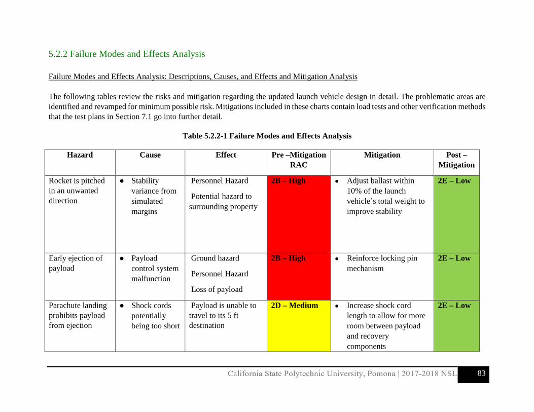
83
5.2.2 Failure Modes and Effects Analysis Failure Modes and Effects Analysis: Descriptions, Causes, and Effects and Mitigation Analysis The following tables review the risks and mitigation regarding the updated launch vehicle design in detail. The problematic areas are identified and revamped for minimum possible risk. Mitigations included in these charts contain load tests and other verification methods that the test plans in Section 7.1 go into further detail.
Table 5.2.2-1 Failure Modes and Effects Analysis
Hazard Cause Effect Pre –Mitigation RAC
Mitigation Post – Mitigation
Rocket is pitched in an unwanted direction
● Stability variance from simulated margins
Personnel Hazard
Potential hazard to surrounding property
2B – High
● Adjust ballast within 10% of the launch vehicle’s total weight to improve stability
2E – Low
Early ejection of payload
● Payload control system malfunction
Ground hazard
Personnel Hazard
Loss of payload
2B – High ● Reinforce locking pin mechanism
2E – Low
Parachute landing prohibits payload from ejection
● Shock cords potentially being too short
Payload is unable to travel to its 5 ft destination
2D – Medium ● Increase shock cord length to allow for more room between payload and recovery components
2E – Low

84
Fin damage during vehicle flight
● Dynamic loads cause fin attachments to shear
Vehicle trajectory may vary
2D – Medium ● Reinforce printed PLA fin material
● Reinforce attachment points for fin integration
4E – Minimal
Li-Po Batteries Explosion
● Heating from motor
Swelling
Explosion
2D – Medium ● Batteries moved away from motor
● Servo-controlled rods connect ailerons at the aft end to the batteries
4E – Minimal
Failed Altimeter Reading
● Unable to determine pressure changes
Black powder is not ignited
Parachute fails to deploy
2D – Medium ● Designated holes near the altimeter
2E – Low
Internal Explosion from black powder
● Segments are secured too tightly
Internal explosion
Damaged blue tube
Failed ejection
2D – Medium ● Use appropriate number of shear pins
● Use correct shear pins
2E – Low
Motor Sheared through the rocket
● Motor retention screws shear from bulkhead attachment
Loss of launch vehicle 1C – High ● Use appropriate quantity of screws
● Reinforce with a thicker bulkhead
2E – Low
Parachute fails to deploy
● Shock cords tangled
● Stuck parachute
Parachute doesn’t fully deploy
1C – High ● Ensure the parachutes slide into the body tube with ease
● Added piston mechanism
2E – Low

85
Only a single parachute deploys
● One parachute is stuck
Launch vehicle drifts or descends too quickly
2D – Medium ● Multiple black powder charges triggered in sequence
● Ground testing of ignition system
2E – Low
GPS fails ● Defective ● Damage to
nose cone during flight
Difficulties tracking trajectory and landing
3C – Medium ● Protective structure around avionic
● Multiple devices
3D – Low
Kevlar shock cord breaks
● Overwhelming force
Unintended separation
Falling debris
2D – Medium ● Sewn ends to retain inherent Kevlar strength
1E – Low
Unintended Motor Ignition
● Accidental contact with heat source
Unintended explosion 1C – High ● Motor contained in designated storage
● Motor is the final component to be assembled
1E – Low

86
Verification Methods
Hazard Verification Method Description
Payload locking pin mechanism failure
Load Test Testing for maximum strength of pin housing and readjusting PLA material to ensure proper fit during dynamic loads
Payload Orientation not Corrected at Landing
Drop Test Ensure the SPOC system provides orientation correction during dynamic movements
Fins Shear during Flight
Load Test Test for appropriate strength of PLA material to improve manufacturing techniques and improve screw attachment points
Defective Altimeter Pressure Test Vacuum Bagging and simulating pressure changes to verify corresponding changes in detected altitude
Thrust retainer screws detach from bulkhead
Load Test Testing for maximum strength of bulkhead and selecting thickness with appropriate safety factor
Partial Parachute Deployment
Pressure and Fitting Test Testing parachute packing methods with black powder charges

87
5.2.3 Environmental Hazard Analysis
Environmental Hazard Analysis: Descriptions, Causes, and Effects and Mitigation Analysis Environmental concerns regarding the launch vehicle revolves around the exterior features and the engine combustion. Therefore, precautions are taken to avoid the aforementioned hazards. The following tables indicate how the launch vehicle is affected by the environment, and more importantly, how the launch vehicle affects the environment. The nose cone, fins, and body tube have negligible effect on the environment. However, the opposite is not true. The exterior frame is susceptible to weather changes. The blue tube, made of cellulose fiber, deforms if the moisture absorption surpasses its threshold and adversely affects structural and aerodynamic integrity. Similarly, wood can expand with moisture and cause cracks to form. The nose cone, although very unlikely, may have its PLA plasticize if it is exposed to sources of high heat and affect the attachments and form. Therefore, the team is prepared to diligently comply to the pre-launch checklist to ensure procedures are completed in a timely manner and avoid prolonged exposure to the sun. The best solution is to avoid these types of environments during the launch window and reschedule the event if necessary. The team is well aware of the fact that our launch sites are prone to the rainiest weather during the month of February. The team will also be prepared to face possible rescheduling of launches during the months of January and March due to rainy weather. Additionally, launches will take place during the earliest hours of the day to avoid interference from windy conditions. The motor poses greater risk to the environment’s well-being because ammonium perchlorate is extremely potent to wildlife. This mixture can contaminate waters and cause retardation in wildlife. When the mixture is combusted, the byproduct reacts with water to form hydrochloric acid, which causes corrosion in epidermal and internal tissues. Though the inherent danger of these chemicals cannot be altered, the overall effects are reduced when launching in an isolated area diluting the chemical concentration. In the event of a failed ejection, the carbon fiber debris made from the onboard components also raises concerns. These fibers are not biodegradable and may become choking and puncturing hazards. Therefore, the current launch vehicle design minimizes these dangers by enclosing carbon fiber component to minimize debris radius upon landing and reducing overall fiber usage. The team intends on conducting at least four launch tests throughout the course of the rocket’s completion. Between the three launch sites that will be utilized, the average mileage travelled to the site from and back to campus is approximately two hundred sixty miles. With the average vehicle having about twenty five mpg, one trip to a launch site would require more than ten gallons of gas. For every gallon of gas burned, almost nine thousand grams of carbon dioxide are emitted into the atmosphere. Carbon dioxide emissions have been, and remain to be, a great concern and threat to society. Though the number of trips made to launch tests can be limited to a certain degree, the number of vehicles used by the team can most certainly be reduced. Each launch test estimates

88
to have at least eight members present. Therefore, the team has set forth a carpooling system in place to ensure the most is done to reduce its impact on the environment. All three of the launch sites visited are located on desert terrain. With that being said, the desert is home to a number of wildlife that need to be taken into consideration when entering their habitat. The Mojave Desert for example, where two of the launch sites are established, harbors ants, bugs, snakes, rodents, spiders, scorpions, desert tortoise, and more. Prior to departing from campus to a launch test, the safety officer will check-in with each member to certify each member is wearing proper desert attire, to avoid possible life-threatening lesions, and alertness, to ensure caution is taken when coming across holes in the turf.
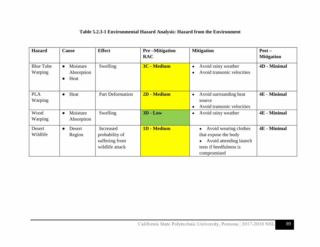
89
Table 5.2.3-1 Environmental Hazard Analysis: Hazard from the Environment
Hazard Cause Effect Pre –Mitigation RAC
Mitigation Post – Mitigation
Blue Tube Warping
● Moisture Absorption
● Heat
Swelling 3C - Medium
● Avoid rainy weather ● Avoid transonic velocities
4D - Minimal
PLA Warping
● Heat Part Deformation 2D - Medium ● Avoid surrounding heat source
● Avoid transonic velocities
4E - Minimal
Wood Warping
● Moisture Absorption
Swelling 3D - Low ● Avoid rainy weather 4E - Minimal
Desert Wildlife
● Desert Region
Increased probability of suffering from wildlife attack
1D - Medium ● Avoid wearing clothes that expose the body ● Avoid attending launch tests if heedfulness is compromised
4E - Minimal

90
Table 5.2.3-2 Environmental Hazard Analysis: Hazard to the Environment
Hazard Cause Effect Pre –Mitigation
RAC Mitigation Post –
Mitigation
Ammonium Perchlorate
● Storage Malpractice
Contamination
Wildlife development retardation
2B - High ● Store in designated box ● Avoid unnecessary
transportation and contact
2E - Low
Hydrochloric Acid
● Motor byproduct
Corrosion
Toxicities in wildlife
2B - High ● Test in desolate areas 2E - Low
Carbon Fiber ● Debris from failed recovery event
Choking and puncture hazards
Not degradable
3C - Medium ● Reduce carbon fiber usage ● Contain carbon fiber
components
4C - Minimal
Carbon Dioxide Emissions
● Automobiles as transportation
Increases the greenhouse effect
1A - High ● Reduce the number of vehicles used by ridesharing

91
5.2.4 Safety Officer Identified Responsibilities Safety Officer, Chemical Engineer Natalie Aparicio [email protected] 323-919-0223 Safety Officer Responsibilities
1. Generate a launch and safety checklist by FRR submission and used during launch days and LRR
2. Filter out unsafe designs of the launch vehicle and payload experiments 3. Compliance of team members to wear safety equipment and follow procedures carefully
during manufacturing 4. Monitor team activities during:
a. design of vehicle and launcher b. construction of vehicle and launcher c. assembly of vehicle and launcher d. ground testing of vehicle and launcher e. recovery testing f. sub-scale testing g. full scale testing h. launch day i. educational engagement activities
5. Implement procedures for construction, assembly, launch, and recovery activities 6. Manage, maintain, and write the team’s hazard analyses, failure mode analyses, procedures
for the overall launch vehicle system, and the payload experiment 7. Attain and record all MSDS of materials used during construction and assembly 8. Write and enforce document stating that the team will abide by the rules of the FAA 9. Write and enforce document stating that the team will abide by local rocketry club’s RSO
during test flights 10. Determine all the risks and delay impacts and analyze the means of mitigation 11. Determine environmental concerns and effects of the launch vehicle system and payload 12. Create a Safety Compliance Document to fulfill Requirement SR4.5 and SR4.6 13. Before test flights, shall remind team of the rules and guidance of the local rocketry club’s
RSOs 14. Shall ensure team followed rules set forth by the FAA

92
6.0 Payload Criteria: Design of Payload Equipment
6.1 Final Design: Components and Justification
6.1.1 Deployment System
The leading deployment system chosen was the System Protection and Orientation Correction (SPOC) system, alternative 1 from the PDR. The pendulum system, seen in Figure 6.1.1-1 below, since displaced from the launch vehicle’s CG allows for the rover to turn within SPOC. The rover’s CG is close to the ground and thus the rover remains upright within the deployment system independent of the launch vehicle orientation. This system allows for easy deployment of the rover as it just needs to begin rolling out upon landing down a stationary ramp. The schematics of the SPOC consists of an outer ring bolted to the inside of the launch vehicle maintaining its position, and an inner frame which actually holds that rover that is free to rotate within the outer ring upon landing. Connecting the rover to the inner frame is a small locking pin attached to the SPOC system. The rover is locked into place preceding launch using servo on the rover. During flight, the inner ring is held stationary with the outer ring by a locking pin. When the main shoot deploys, it pulls out the locking pin allowing the inner frame and rover to rotate to an upright position. This has been the chosen design of the deployment system because it is inexpensive and easily manufactured, made by a 3D printer, also upholds a very simple design with little room for failure.
Figure 6.1.1-1 Selected Rover Deployment System

93
6.1.2 Solar Panels
The solar panels chosen to be on the rover are 4 AMX3d Micro Solar Cells, Figure 6.1.2-1. These are ideal solar panels because they are very inexpensive, small, and light-weight as the dimensions are 2.09x1.181x0.1181in. and weigh less than 0.02 lbs., which consequently make them ideal size for the rover. The panels operate at 5V and are capable of producing up to 3.7V. These panels will also have a very smooth and simple deployment as they will be held in a closed, face down position on top of the rover, by a servo. Upon release, the solar panels will spring out and will be opened up at a 180-degree angle, held in place by 180-degree torsion springs on either side.
Figure 6.1.2-1: Micro Solar Cells selected for Rover
6.1.3 Avionics
The Raspberry Pi Zero was chosen as the command center for the avionics of the rover. Although the main competitor of the Pi was an Arduino board, the Pi Zero was ultimately the chosen design during preliminary review and continues to serve the chosen design for the conceptual review for its ability to handle multiple tasks at one time. The Pi will be connected to multiple servos, for purposes of unlocking the rover from the pendulum system and for deployment of the solar panels. The Raspberry Pi Zero, as seen in Figure 6.1.3-1, was chosen by a team member who is fluent in the setup, use, and coding of a Raspberry Pi for various tasks and its understandings. The Eggfinder was the leading alternative for the GPS tracking system, and can be seen in Figure 6.1.3-2. The Eggfinder is easy to install, user-friendly, and an inexpensive choice making it ideal choice to meet the needs of this competition and for the team.

94
Figure 6.1.3-1: Raspberry Pi Camera Module V2(left), Raspberry Pi Zero v1.3 (right)
Figure 6.1.3-2 Eggfinder GPS Tracking System with Dimensions

95
6.2 System Level Design
6.2.1 Payload Assembly
After considering the pros and cons for each rover architecture, the team concluded that the ideal rover design would be DARIC. As shown in Figure 6.2.1-1 and Figure 6.2.1-2, DARIC’s design allows for easy installation of electrical components because of its accessible component bays. Each component will be manufactured by using 3D printers with PLA material and assembled with nuts and bolts.
Figure 6.2.1-1: Trimetric View of assembled DARIC rover
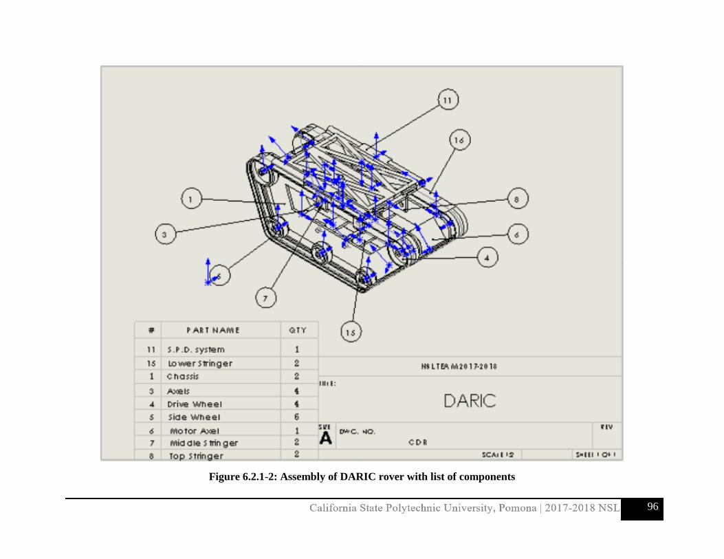
96
Figure 6.2.1-2: Assembly of DARIC rover with list of components

97
6.2.2 Component Drawings and Specifications
The following drawing hold dimensions in inches.
Figure 6.2.2-1: Dimensioned Drawing of chassis (similar for mirrored chassis)

98
Figure 6.2.2-2: Dimensioned Drawing of Top Stringer
Figure 6.2.2-3: Dimensioned Drawing of Middle Stringer

99
Figure 6.2.2-4: Dimensioned Drawing of Lower Stringer
6.2.2-5: Dimensioned Drawing of Drive Wheel (similar design for side wheel)

100
6.2.2.1 Deployment System
The rover will be deployed from the System Protection and Orientation Correction (SPOC) system. The SPOC system will provide a carriage to secure the rover in place during flight, and be prevented from rotating as to provide stability to the launch vehicle. Once the main parachute is deployed, a locking pin, which is tethered to the parachute, will be pulled out allowing the system to freely rotate. When the launch vehicle lands, the weight of the rover will drive the SPOC system to rotate so that the rover’s tracks are facing downward. The rover will then, under command from the ground team, be able to drive off the platform and out of the launch vehicle where the main parachute was deployed from. The SPOC system will be 3D printed from PLA, and consist of two outer rings, and one inner ring. The carriage will be secured to the inner ring. The only connection between the inner and outer rings will be by 0.25 in. steel balls. The carriage system is designed to hug the rover, which will secure it into place. It is locked onto the carriage via a servo on the rover itself, which is disengaged upon landing. The SPOC system provides an easy solution to ensure the rover will be able to land in the correct orientation, and be able to exit the launch vehicle. It only uses mechanical devices, which makes for a less complex and less expensive system.
Figure: 6.2.2.1-1: System Protection and Orientation Correction (SPOC) system

101
Figure 6.2.2.1-2: SPOC Dimensions
Figure 6.2.2.1-3: 3D printed component for SPOC

102
6.2.2.2 Solar Panels
The Solar Panel Deployment System is designed to deploy the solar panels using only the control surface provided by the rotor servo. As shown in Figure 6.2.2.2-1, the rotor servo is the only component holding the panels down. Once the linkage is rotated out of contact with the solar panels, they are automatically deployed as shown in Figure 6.2.2.2-2. The torsion springs are what provide the force to open up the deployable panels and are mounted between the deployable panel and SPD pin. The two main components needed to successfully deploy the panels are the torsion springs and the rotor servo. The main advantage of this design is that it provides a simple assembly that can be easily integrated to the top of the rover. The following drawings are dimensioned in inches therefore they are in English units.
Figure 6.2.2.2-1: Trimetric view of deployed S.P.D. system

103
Figure 6.2.2.2-2: Assembly of deployed S.P.D. System with list of components
Figure 6.2.2.2-3: Dimensioned drawing of Main Panel

104
Figure 6.2.2.2-4: Dimensioned drawing of Deployable Panel Left
Figure 6.2.2.2-5: Dimensioned drawing of Deployable Panel Right

105
Figure 6.2.2.2-6: Dimensioned drawing of SPD Pin
Figure 6.2.2.2-7: Dimensioned drawing of SPD Rod

106
6.2.3 Payload Component Interactions The hardware of the payload will mainly interact through the RPi computer. The XBee transceiver is connected to the RPi through a RPi/XBee shield, which is held together using a 40 pin header. The command to run the rover will be sent through the XBee. Once received, the RPi will use pulse width modulation (PMW) to control the two servos and motor. The first servo will unlock the rover from the SPOC platform. The second servo will deploy the solar panels. The Eggfinder GPS is a stand-alone system, which will only pull power from the RPi to function. The power bank will provide all power needed to the RPi, connected by a micro USB cable.
Figure 6.2.3: Payload component interactions
6.2.4 Payload Integration to Launch Vehicle
The payload integrates into the launch vehicle via the SPOC system. The SPOC system is bolted to the upper vehicle tube (module 3) with 12 3-48 standard bolts. The locking pin preventing rotation during flight will be tethered to the main parachute by a ⅛ in. steel braided cable. Only mechanical integration will be used.
Figure 6.2.4-1: SPOC system showing bolts into LV body tube

107
Figure 6.2.4-2: Locking pin to prevent rotation during flight
Figure 6.4.2-3: Side view of locking pin
6.3 Payload Derived Requirements and Risk Matrix
The deployment systems aforementioned above were found to be the most suitable for its interaction with the rover and integration with the launch vehicle. These leading designs are complete and ready for the full-scale rocket. This risk matrix digs deeper into the details of the payload system.

108
REQ# Description 1 2 3 4 V IP NV
DR12.0
The fastening system of rover to the pendulum system is required to retain stability
throughout flight and ground impact to resist 10G's.
7.1.3.1.1 x Scheduled for February 2, 2018 1 1
DR13.0The CG of the rover is offset from the rockets by at least 40% of the length to achieve the
pendulum system function.6.1.1 x Scheduled for February 2, 2018 1 1
DR14.0The rover must be able to perform all mission functions and remain in standby for 3 hours
using less than 5000 mWh of power.6.2.1 x Scheduled for February 2, 2018 1 1
DR15.0 The rover must be able to be remotely activated within a range of 3000 ft. 6.2.1 x Scheduled for February 2, 2018 1 1
Notes Totals 0 5 0
1
StatusSection Risk
Level
2Scheduled for January 19, 2018
Verification Details
Verifiable through testing. The rover will be given a maximum of 5000 mWh of power and will be left in standby for 3 hours. It will then
receive commands to execute all functions, including deployment from the launch vehicle. After moving at least 5 ft, deployment of solar panels will take place. The rover must also be
tracking movement through the GPS system and the camera system.
Payload Requirements (Derived Requirements) Verification Method
Verifiable through testing. The pendulum system will undergo a series of drop tests. The first drop tests will ensure the SPOC system
bolts inside the launch vehicle will hold, and we will use some deadweight inside to represent the weight of the rover. In the next test, it will lock the deadweight to the SPOC system by a servo
to ensure the hook will be able to hold the rover's mass throughout flight. The last test will be another drop test with the actual rover inside
the SPOC system. All drop tests will be performed from about 40.0 ft.
Verifiable through testing. The rover will be placed 3000 ft from the computer, and
commands will be sent to begin movement and deployment to ensure the rover receives signal
from up to 3000 ft away.
Verifiable through testing. The battery will be drained and recharges to no more than 2%. At
this point, a command to deploy the solar panels will be sent. If successfully executed, the solar deployment will prove to use only 2% battery
life or less.
DR11.0
Verifiable through analysis. The complete design of the launch vehicle will be used to compute the launch vehicle's CG. Then the
placement of the rover in the launch vehicle will then be varied and calculated until it's found to
be 40% offset from the launch vehicle's CG.
6.2.2.1 & 6.2.2.2 xThe solar deployment system requires a
maximum of 2% battery life.
Design Requirements & Risk Mitigation

109
6.4 Payload Electronics
6.4.1 Payload Electronics Overview
This section will cover how the different electronics systems inside the payload, mainly that of the Raspberry Pi Zero, will interact with each other to complete the mission at hand. On the payload are a micro SD card, a micro USB to log data, Eggfinder GPS system, the Raspberry Pi Zero W along with the Sixfab Shield and Xbee transceiver unit. In addition to the purely electronic components are the motorized components which include the main driving motor and two servo motors. As stated previously, the payload will be a self-contained system, designed to gather, store, and transmit data, while also carrying out its mission. As previously stated, due to the change from an Adafruit transceiver to Xbee modules on the rover, the ground station will consist of the Eggfinder RX and an Xbee independently connected to a laptop via USB. The Eggfinder will be receiving GPS data from the rover, while the pair of Xbees will communicate with each other. The ground station Xbee will ultimately send a signal to the Xbee on the rover to begin its autonomous cycle. 6.4.1.1 Drawings and Schematics Seen below are the drawings and schematics of how the motor system on the rover will be wired together. This system includes the two servos getting their power directly from the raspberry pi that will be plugged into the battery, the main motor with its own transistor, a GPS module, and one of the two Xbee Shields to be used for communication.
Figure 6.4.1-1: Drawing of Motor and GPS System on Rover

110
Figure 6.4.1-2: Motor and GPS System Schematic

111
6.4.1.2 Block Diagrams
These are several different block diagrams depicting what is happening in the individual processes. Included are the diagram for the motor, the two servos, the GPS, and the Xbee Shield.
Figure 6.4.1.2 -1: Block Diagrams relating the motor, servos, GPS, and Xbee Shield

112
6.4.1.3 Batteries/Power
The rover will have one to two long lasting Lipo batteries capable of producing a constant 5.5V. It is estimated that the electronic systems of the rover will be active for at least 2 to 3 hours before launch, so this battery is long lasting. Electricity will be transmitted from this battery onto the Raspberry Pi board to where current can flow to each specified component. The main driving motor will be using the most power throughout the mission as it is in use for the most time. Additional uses of power will be the Eggfinder GPS and the Xbee Shield as well as the two servos to unhook the rover and to unlatch the servo setup.
6.4.1.4 Switch and Indicator Wattage and Location
The payload electronics system will be turned on and inserted into the rocket on the day of the launch, thus deeming the process of an on switch unnecessary. The location of the on-switch will be near the backside of the rover around where the gyroscopic mount will be located. This allows for the system to be fully operational around time of the drop.

113
7.0 Project Plan
7.1 Test Plans The following test plans have been carefully designed in order to prove the integrity of the launch vehicle and its payload.
7.1.1 Launch Vehicle Test Plans
7.1.1.1 Subscale Launch Test
Objective:
Requirement Verification
Success Criteria Test Variable: Measured/Controlled
Status
Verify Req. 2.16 by demonstrating the launch vehicle will have a minimum static stability margin of 2.0
Verify Req. 2.18.1 to demonstrate that that the launch vehicle shall be designed to be recoverable and reusable.
Verify Req. 2.18.2 by carrying an altimeter to report the model’s apogee.
The launch vehicle will be recoverable and reusable with an on-board altimeter capable of reading the apogee. The launch vehicle’s flight will demonstrate accurate stability.
Controlled:
-Subscale launch vehicle design
-Stability margin
Measured:
-Flight data from altimeters
Completed:
1/6/18
Methodology
The launch of the subscale model incorporated all the procedures outlined in section 5.1. Scaling factors were used to design a vehicle half the size of the full-scale launch vehicle while ensuring

114
the stability margin was acceptable. The launch of the subscale is intended to demonstrate the integrity of the full-scale design and its stability.
Subscale launch procedure:
1. Confirm the pre-flight checklist has been completed. 2. Carefully slide the launch vehicle onto the provided rails at the launch site. Align the launch
rail to the appropriate position. Ensure that the igniter is properly placed. 3. When the launch vehicle is in its launch configuration, arm the switches for the electronics
from the exterior of the vehicle’s airframe. 4. The LCO will enable the master arming switch and will then activate the hard switch upon
confirmation and safety checks have been completed. 5. The LCO will commence the countdown and will say “fire” for the ignition switch to be
triggered. 6. All team members will visually track the launch vehicle from ignition to its landing. 7. Once the launch vehicle has landed and the area is safe from any potential launch vehicle
flight hazards, the team members shall accompany the team mentor to inspect the launch vehicle.
8. Team members shall not touch the vehicle until the mentor has inspected it. Once cleared, team members shall complete the post-flight checklist.
9. Document the launch vehicle with photographs for the later assessment, then recover the launch vehicle.
10. Review the flight data and photographs.
Equipment
• Structural components necessary for the subscale manufacturing (listed in the subscale budget)
• 12-volt direct firing system • Motor and igniter (to be handled by the team L2 certified mentor) • Assembly and manufacturing tools • Safety PPE necessary as outlined in section 5.0.
Results
The subscale launch vehicle was successfully recovered and in reusable condition. The subscale demonstrated a straight flight during ascent with a successful flight profile. The electronics function as necessary with an altimeter reading of 4,313 ft. Data and results are further discussed in section 4.2.5. The results were significant in demonstrating that the structural design of the full-scale launch vehicle will produce an appropriate static stability margin. It also revealed what minor adjustments should be made to improve the integrity of the full-scale launch vehicle’s recovery system.

115
7.1.1.2 Full-scale Launch Test
Objective:
Requirement Verification
Success Criteria Test Variable: Measured/Controlled
Status
Verify Req. 2.1 to ensure that the launch vehicle will deliver the payload to an apogee of 5,280 ft.
Verify Req. 2.6 by designing the vehicle to be recoverable and reusable.
Verify Req. 2.19 to demonstrate that the vehicle will be successfully launched in its final flight configuration and recovered prior to FRR.
The full-scale launch vehicle reaches an apogee altitude of 5,280 ft. 75 ft. The launch vehicle is determined recoverable and usable for another launch. A successful flight is completed before 3/5/18 (FRR).
Controlled:
-Subscale launch vehicle design
-Stability margin
Measured:
-Flight data from altimeters
Scheduled:
2/3/18
2/10/18
Backup dates:
2/17/18
2/24/18
Methodology
The launch of the full-scale vehicle will incorporate all the procedures outlined in section 5.1. The test is designed to ensure that any necessary changes will be made to the launch vehicle pending launch test results. The launch of the full-scale is intended to demonstrate the integrity and safety of its design and its stability. A minimum of two launch tests will be conducted with two backup dates in the project plan if further analysis is needed.
Equipment
• Structural components necessary for the full-scale manufacturing (listed in the full-scale budget)
• 12-volt direct firing system • Motor and igniter (to be handled by the team L2 certified mentor) • Assembly and manufacturing tools • Safety PPE necessary as outlined in section 5.0.
Full-scale launch procedure:
1. Confirm the pre-flight checklist has been completed.

116
2. Carefully slide the launch vehicle onto the provided rails at the launch site. Align the launch rail to the appropriate position. Ensure that the igniter is properly placed.
3. When the launch vehicle is in its launch configuration, arm the switches for the electronics from the exterior of the vehicle’s airframe.
4. The LCO will enable the master arming switch and will then activate the hard switch upon confirmation and safety checks have been completed.
5. The LCO will commence the countdown and will say “fire” for the ignition switch to be triggered.
6. All team members will visually track the launch vehicle from ignition to its landing. 7. Once the launch vehicle has landed and the area is safe from any potential launch vehicle
flight hazards, the team members shall accompany the team mentor to inspect the launch vehicle.
8. Team members shall not touch the vehicle until the mentor has inspected it. Once cleared, team members shall complete the post-flight checklist.
9. Document the launch vehicle with photographs for the later assessment, then recover the launch vehicle.
10. Review the flight data and photographs.
Results
To be determined; test will be conducted on 2/3/18 and 2/10/18 with backup launches scheduled for 2/17/18 and 2/24/18.
7.1.1.3 Bulkhead Test
Objective:
Requirement Verification
Success Criteria Test Variable: Measured/Controlled
Status
Verify Req. DR2.0 and 3.0 to show that all bulkheads must be able to withstand launch vehicle loads, specifically the hollowed bulkhead designed for Payload integration.
The bulkhead shall maintain its integrity without signs of structural degradation.
There shall be no shear tear out from any fasteners. Attachment points will sustain bearing stress.
Controlled: Bulkhead material, body tube, and attachment hardware.
Measured: Damage sustained from critical components; fastener attachment points.
Scheduled:
1/17/18

117
Methodology
The bulkhead test will consist of a static load test. It will be conducted in order to prove the integrity of all bulkheads and the hollowed bulkhead, which has been designed to contain the payload. The load test will determine if all bulkhead components and attachments will withstand the launch vehicle’s flight. The test is important in ensuring that the launch vehicle will be recoverable and reusable. It is also critical to confirm that the payload will be safely protected from launch vehicle loads.
Bulkhead test procedure:
1. The Safety Officer shall provide clearance for the test to be conducted after ensuring team members are aware of all safety hazards.
2. Ensure bulkhead is appropriately fixed to body tube and that all hardware has been attached. Bulkhead component should resemble closely as possible to its launch configuration state in the launch vehicle.
3. Secure the bulkhead component and attach a tethered shock cord to the U-bolt. 4. Attach loading to U-bolt beginning at 50 lb, then increase weight gradually. 5. Continue previous step until bulkhead begins to yield. Collect data and results.
Equipment
• Safety glasses and heavy-duty gloves • Shock cord • Bulkhead • Body tube (Blue Tube) • Fasteners and U-bolt • Test weights
Results
To be determined; test will be conducted on 1/17/18.

118
7.1.1.4 PLA Materials Test
Objective:
Requirement Verification
Success Criteria Test Variable: Measured/Controlled
Status
Verify Req. DR8.0 to show that all PLA materials shall withstand launch vehicle loads, specifically the fins.
PLA material shall not experience shearing, bearing stress, or any other significant loads that would cause degradation to the material.
Controlled:
-Fasteners
-Bulkhead
-Blue Tube
Measured:
-Deformation of PLA
-Displaced area where fasteners are attached
Scheduled:
1/24/18
Methodology
This test is vital in proving the integrity of all components containing PLA, which include the hollowed bulkhead, nose cone, fins, and components for the payload. There will be two tests designed to analyze the impulse produced by an impact force transferred to the screws. The test will pull on the PLA plastic, which will generate a normal force in the opposite direction. The second part of the test consists of a static load test that will be applied to a bulkhead attached to the PLA. This test will be performed to ensure that the PLA plastic can withstand the load equal to the impulse resulting from the velocity of the nose cone and fins during the launch vehicle ascent and descent phases.
PLA materials test procedure:
1. The Safety Officer shall provide clearance for the test to be conducted after ensuring team members are aware of all safety hazards.
2. Ensure bulkhead is appropriately fixed to body tube and that all hardware has been attached. Bulkhead component should resemble closely as possible to its launch configuration state in the launch vehicle.
3. Secure the bulkhead component and attach a tethered shock cord to the U-bolt. Suspend component via and overhead crane.
4. The SO will ensure all obstacles within reach of the testing area are removed, and that all individuals involved are wearing the appropriate PPE.
5. Lift the test component to the predetermined height. The tester will alert the viewer that the test will commence. One alerted, proceed with a countdown.

119
6. After test component has been released and the area is safe to approach, make note after a visual inspection is completed.
7. Document the test with photos for later assessment. 8. Repeat steps 3 - 7 by increasing the height until failure is experienced or until drop velocity
is much greater than what the component will experience during launch vehicle loads during flight.
9. Perform the static test by hanging various weights to determine shear. 10. Document the test results by written description and photos.
Equipment
• Safety glasses and heavy-duty gloves • Shock cord • Bulkhead • Body tube (Blue Tube) • Fasteners and U-bolt • Test weights • Cylindrical PLA tube • Anchor chain • Measuring tape • Ladder
Results
To be completed; test will be conducted on 1/24/18.
7.1.1.5 Observation System Test
Objective:
Requirement Verification
Success Criteria Test Variable: Measured/Controlled
Status
Raspberry Pi Zero with camera will provide flight profile verification
Camera must be capable to record for a minimum of 1 hour
• Battery capability • Raspberry Pi Zero
computer and camera must be functionable
Completed:
1/15/18
Methodology
The observation system will simply be connected and programed to verify the camera records, saves, and plays back.

120
Observation system test procedure:
1. Connect camera with Raspberry Pi Zero computer 2. Connect observation system to computer and download any required software 3. Program Raspberry Pi Zero to begin recording 4. Save and playback test recordings
Equipment
• Raspberry Pi Zero and camera
• Battery pack
• Micro SD
• Provided USB cables
• Any computer with USB connection
Results
• To be completed; test will be conducted on 1/20/18
7.1.2 Recovery System Test Plans
7.1.2.1 Parachute Drop Test
Objective: Requirement Verification
Success Criteria Test Variable: Measured/Controlled
Status
Verify Req. 3.1 and 3.3 to ensure that the provided kinetic energy during drogue-stage descent is reasonable. Verify Req. 3.3 to ensure the kinetic energy does not exceed 75 ft-lb by determining the parachutes’ velocity.
Predicted parameters are verified. The drogue and main parachutes completely inflate.
Controlled: -5 lb. weight -Parachute size -Drop distance height Measured: -Descent time -Parachute inflation
Scheduled: 1/28/18
Methodology A drop test will be used to prove the integrity of the launch vehicle’s recovery system. This test will be conducted for both the drogue and main parachutes. Video will be recorded for analysis

121
after each test has been completed. The video will be used to monitor parachute inflation and shroud line tendency for tangling. Parachute drop test procedure:
1. Determine appropriate drop test area and measure the height of the drop distance. 2. Secure the video camera at an angle capable of recording the parachute’s descent. 3. Attach a 5 lb weight to the parachute. 4. Ensure that shroud lines are untangled and that parachute is correctly packed. 5. Begin video recording. 6. Drop the weight and packed parachute. 7. Record results, document with photos, and then collect video data to analyze the
parachute during its descent. Equipment
• Drogue parachute • Main parachute • 5 lb weight • Video camera
Results To be completed; test will be conducted on 1/28/18. 7.1.2.2 Ejection Charge Test
Objective: Requirement Verification
Success Criteria Test Variable: Measured/Controlled
Status
Verify Req. 3.2 by performing a ground ejection test for both the drogue and the main parachutes; to determine the amount of charge necessary for the recovery system.
Both the drogue and main parachute sections eject with enough clearance to pull the shock cord out completely and break all shear pins. No heat damage is sustained to recovery materials. Body tube does not sustain damage where attached to recovery harness.
Controlled: Size of the ejection charge Measured: Lateral distance of each section from its ejected position
Subscale completed: 12/30/17 1/3/18
Full-scale scheduled:
1/27/18
Methodology The ejection charge test will be conducted for both the subscale and full-scale launch vehicles. The recovery system will be setup accordingly to replicate the launch vehicle in its launch pad configuration state. The charge will be sized according to calculations based on vehicle dimensions

122
and then ignited to deploy each parachute. A visual inspection will be conducted to ensure that enough lateral distance was attained. The charge will then be re-sized accordingly to ensure proper deployment. Ejection charge procedure:
1. Administer all precautions to comply with safety regulations set forth by the Safety Officer. 2. Carefully pack each parachute and their shock cords into the body tubes while taking care
to protect the recovery material with Nomex blankets. Make note of the parachute packing in order to simulate its setup during launch testing.
3. Place on the appropriate PPE as deemed by the SO. Measure the amount of ejection charge and prepare.
4. Setup the charge and then secure the bulkhead. Once the charge has been configured, the SO will ensure that the path ahead the nose cone is completely clear.
5. Secure the launch vehicle so that it is angled up into the air and not lying flat on the ground. The SO will ensure that the space around the launch vehicle is now clear.
6. Ignite the ejection charges and wait at least one minute before approaching the vehicle. 7. Assess the deployment distance achieved by inspecting the shock cord length and the
parachute configuration. Document the inspection. 8. Re-size the charge appropriately to ensure sufficient deployment. 9. Repeat steps 1-8 until sufficient deployment is reached.
Equipment
• Cellulose insulation “dog barf” • Nomex blankets for each parachute • Duct tape • Black powder • E-matches • Recovery system components and harness • Launch vehicle components with shear pin attachments • Sandbags (to angle the vehicle upwards) • Necessary PPE as deemed by the SO
Results Subscale launch vehicle: The initial charges were not adequate and did not completely deploy the drogue and main parachutes. After a few attempts at re-sizing the charges, there was sufficient deployment, and thus, revealed a successful test. This test ensured that the subscale design would provide deployment for its recovery system. It also allowed team members to gain practice at proper packing methods for the recovery system prior to launch. This will also ensure that the full-scale launch vehicle shall be recoverable and reusable. Full-scale launch vehicle: To be determined; test will be conducted on 1/27/18.

123
7.1.2.3 Recovery Avionics Shielding Test
Objective: Requirement Verification
Success Criteria Test Variable: Measured/Controlled
Status
Verify Req. 3.11 to ensure that recovery system electronics will not be adversely affected by any other on-board electronics.
Radio frequency signals do not cause adverse effects and signals are greatly reduced within the recovery bay.
Controlled: -RF shielding lining in the avionics bay Measured: -Strength of the RF signal received
Scheduled: 1/16/18
Methodology/Procedure This test will confirm that the launch vehicle recovery avionics will function as needed. This will ensure that the vehicle will be properly recovered in a reusable condition. The signal strength will be tested using the selected recovery avionics components. The test simply involves the avionics bay component with the electronics sealed inside the bay, which will be lined with RF shielding. As the test is conducted, the signal strength will be observed. The test will be successful if signal disconnections do not occur. Equipment
• Avionics bay component • RF shield lining • Recovery avionics
Results To be determined; test will be conducted on 1/16/18. 7.1.3 Payload Test Plans
7.1.3.1 Payload Integration Test – Mount to Launch Vehicle
Objective: Requirement Verification
Success Criteria Test Variable: Measured/Controlled
Status
Verify Req. DR 12.0 to determine mounting of SPOC system into launch vehicle.
The SPOC system remains attached to the launch vehicle tube.
Controlled: -Altitude -Mass Measured: -Mounting locations
Scheduled: 1/20/2018

124
Methodology A drop test will occur to test the launch vehicle tube with the SPOC system mounted inside. The SPOC system will contain a weight attached to simulate the rover. The tube will have a snap cord of 40 ft length attached. When the tube is stopped, the impulse of a launch will be simulated. The bolts and mounting locations of the SPOC system will be examined. Equipment
• Blue Tube • SPOC System • Simulated mass • Snap cord
Results Tentative; test will be conducted on 1/20/2018.
Payload Integration Test – Rover Mount to SPOC Platform
Objective: Requirement Verification
Success Criteria Test Variable: Measured/Controlled
Status
Verify Req. DR12.0 to determine mounting of rover to SPOC system platform.
The simulated weight remains attached to the SPOC platform by the locking servo.
Controlled: -Altitude -Mass Measured: -Locking servo position change (if moved by loads)
Scheduled: 1/19/2018
Methodology A drop test will occur to test. The launch vehicle tube will have the SPOC system mounted inside with a simulated weight representing the rover locked on the platform by the locking servo. The tube will have a snap chord of 40 ft length attached. When the tube is stopped, the impulse of launch will be simulated. The servo and locking method will be examined. Equipment
• Blue Tube • SPOC System • Simulated Mass with locking servo • Snap Chord
Results Tentative; test will be conducted on 1/19/2018.

125
7.1.3.2 Raspberry Pi Test – Rover Operation
Objective: Requirement Verification
Success Criteria Test Variable: Measured/Controlled
Status
Verify Req. DR14.0 to make sure rover CPU performs all parts of the mission and can idle for 3 hours.
The servos and motor rotate when needed, and the Xbee and GPS transmit correctly and remain transmitting for 3 hours.
Controlled: -Run code for the mission -Total test time Measured: -All the functions of the rover -Battery consumption
Scheduled: 2/2/2018
Methodology The RPi will have the two servos, motor, Xbee and GPS connected. The run signal will be sent to the Xbee. The functions of the two servos and motor will be watched and compared to their run schedule. The GPS will also be watched to make sure it operates as intended. Then, the system will remain in standby for 3 hours to ensure that the battery will last. Equipment
• Payload electronics • 5000 mAh battery • Laptop with ground station
Results Tentative; test will be conducted on 2/2/2018
7.1.3.3 GPS Test
7.1.3.4 Xbee Test – Range
Objective: Requirement Verification
Success Criteria Test Variable: Measured/Controlled
Status
Verify Req.DR 15.0 to make sure that the Xbee can receive a signal from 3000 ft distance.
The rover Xbee receives a message from the ground station Xbee.
Controlled: -Distance between the two Xbee transceivers
Scheduled: 1/26/2018

126
Methodology The Xbee dedicated to the rover will be connected to a laptop and placed inside a section of the launch vehicle tube; this will simulate how the signal could be impacted. Another laptop with the ground station Xbee will be placed 3000 ft. away. A message will be sent from the ground station to the rover Xbee. A received message will be a successful test. Equipment
• 2 laptops • Rover Xbee on Xbee/RPi shield • Ground station • Blue Tube
Results Tentative; test will be conducted on 1/26/18.
7.2 Requirements Compliance 7.2.1 Launch Vehicle Compliance Matrix
The requirements compliance matrix for each subsection will be outlined in this section. The requirements compliance matrix gives the following nomenclature:
1 Test2 Analysis3 Demonstration4 Inspection
Method of Verification Table Definition Status V IP NV
Verified In Progress
Not Verified

127
Vehicle Requirements Design Requirements Section
Verification Method Verification Details Status
REQ# Description 1 2 3 4 V IP NV
VR2.1
The vehicle will deliver the payload to an apogee altitude of 5,280 feet above
ground level (AGL).
The vehicle was found to deliver the payload
to approximately 5,280 feet and meet
the minimum rail exit velocity of 52 ft/s.
4.1.2 &
4.3.2 x x
OpenRocket simulations of final design provide
projected altitude, launch tests shall showcase
altitude reached.
1
VR2.2
The vehicle will carry one commercially
available, barometric altimeter for recording
the official altitude used in determining the altitude award winner. Teams will receive the maximum number of altitude points (5,280) if the official scoring
altimeter reads a value of exactly 5280 feet AGL. The team will
lose one point for every foot above or below the
required altitude.
An altimeter will be used to record flight data such as altitude
and temperature and to initiate parachute
deployment at predetermined
altitudes.
5.1.1
x
The team shall review the launch vehicle system,
subsystems and components design
verifying at least one commercially available
altimeter.
1

128
VR2.3
Each altimeter will be armed by a dedicated arming switch that is accessible from the
exterior of the rocket airframe when the
rocket is in the launch configuration on the
launch pad.
Two 1/2 in. holes will be made on the
recovery avionics bay to allow room for
arming switches that may be accessed from
the exterior.
5.1.1
x Verify the dimensions are
the appropriate size for the selected switches.
1
VR2.4 Each altimeter will
have a dedicated power supply.
The avionics bay includes two sets of the altimeters each
with its own independent power
supplies.
4.1.3.4 x
x Inspection of altimeter schematic design 1
VR2.5
Each arming switch will be capable of
being locked in the ON position for launch (i.e. cannot be disarmed due
to flight forces).
Each altimeter will be armed using a rotary
switch that is accessible from the outside of the body
tube. The rotary switch will be toggled using a flat head screw driver and cannot be
disarmed due to flight forces.
4.1.2, 4.3.5
& 4.3.6
x Inspection of altimeter schematic design 1

129
VR2.6
The launch vehicle will be designed to be recoverable and
reusable. Reusable is defined as being able to
launch again on the same day without
repairs or modifications.
The rocket will be designed to be reusable and
recoverable before flight day.
4.1.2 & 4.4 x
Conducting launch tests shall be able to result in a
usable vehicle afterwards. The
Structures team shall design the structure to be
robust and withstand impact loads through
testing.
1
VR2.7
The launch vehicle will have a maximum of four (4) independent
sections. An independent section is
defined as a section that is either tethered to the main vehicle or is recovered separately
from the main vehicle using its own
parachute.
The launch vehicle will have three
independent sections known as modules.
4.1.2
x Final build will verify
three independent sections.
1
VR2.8 The launch vehicle will
be limited to a single stage.
Launch vehicle will be limited to a single
stage.
4.1.3.3
x x Final build will verify the rocket is single-stage. 1
VR2.9
The launch vehicle will be capable of being prepared for flight at
the launch site within 3 hours of the time the
Federal Aviation Administration flight
waiver opens.
Modular design of the launch vehicle sections, where
assembly only requires fastening of each
module with shear pins.
4.4.1
x
Before test launches, the team shall time the
preparation of the launch vehicle.
1

130
VR2.10
The launch vehicle will be capable of
remaining in launch-ready configuration at the pad for a minimum
of 1 hour without losing the functionality of any critical on-board
components.
Launch vehicle must be in ready
configuration at a minimum of 1 hour.
4.4
x
Before test launches, the team shall demonstrate if the vehicle can be read on the stand for 1 hour.
1
VR2.11
The launch vehicle will be capable of being
launched by a standard 12-volt direct current
firing system. The firing system will
be provided by the NASA-designated
Range Services Provider.
Launch vehicle shall be launched with a 12
Volt direct current firing system.
4.4 x
Launch tests shall be done with a 12 Volt
firing system proving its ability to function.
1
VR2.12
The launch vehicle will require no external circuitry or special
ground support equipment to initiate
launch (other than what is provided by Range
Services).
Launch vehicle shall have no external
circuitry. 4.4
x Inspection of the electrical circuitry design 1
VR2.13 4.1.2 x 1

131
The launch vehicle will use a commercially
available solid motor propulsion system using ammonium
perchlorate composite propellant (APCP)
which is approved and certified by the
National Association of Rocketry (NAR), Tripoli Rocketry
Association (TRA), and/or the Canadian
Association of Rocketry (CAR).
Launch vehicle will utilize a commercially
bought Aerotech L1420 solid propellant
motor.
Aerotech L1420 motors are still commercially
available.
VR2.15
The total impulse provided by a College
and/or University launch vehicle will not exceed 5,120 Newton-
seconds (L-class).
Total impulse of Aerotech L1420 does
not exceed 5,120 Newton-seconds.
4.1.2 x x
Company provided specifications verify the
impulse. 1
VR2.16
The launch vehicle will have a minimum static stability margin of 2.0 at the point of rail exit. Rail exit is defined at the point where the forward rail button
loses contact with the rail.
The launch vehicle will be a stability margin of 2.04.
4.4.6
x
OpenRocket simulations have verified current
static stability margins. Further calculations will be made when the full-
scale rocket is built.
1

132
VR2.17
The launch vehicle will accelerate to a
minimum velocity of 52 tips at rail exist.
The motors of the launch vehicle were found to meet the minimum rail exit velocity of 52 ft/s.
4.1.2
x
Simulations shall be conducted to analyze the
minimum velocity.
1
VR2.18
All teams will successfully launch and
recover a subscale model of their rocket
prior to CDR. Subscales are not
required to be high power rockets.
A subscale model will be launched and
recovered prior to the CDR.
7.4.1 &
7.4.2 x
x
Launch day will verify the success of launch and
recovery.
1
VR2.18.1
The subscale model should resemble and
perform as similarly as possible to the full-
scale model, however, the full-scale will not
be used as the subscale model.
The subscale model will perform similar to the full-scale model.
7.1.1 &
7.1.1.1
x
x
Launch day will verify that the subscale will perform similar to the
full-scale model.
1
VR2.18.2
The subscale model will carry an altimeter
capable of reporting the model's apogee
altitude.
The subscale model will carry an altimeter capable of reporting the model's apogee
altitude.
7.1.1 &
7.1.1.1
x x
Visual inspection will be made on launch day to
verify the use of an altimeter.
1

133
VR2.19
All teams will successfully launch and recover their full-scale rocket prior to FRR in
its final flight configuration. The
rocket flown at FRR must be the same
rocket to be flown on launch day. The
purpose of the full-scale demonstration
flight is to demonstrate the launch vehicle’s stability, structural integrity, recovery
systems, and the team’s ability to prepare the
launch vehicle for flight. A successful flight is defined as a launch in which all
hardware is functioning properly (i.e. drogue chute at apogee, main
chute at a lower altitude, functioning
tracking devices, etc.). The following criteria must be met during the
full-scale demonstration flight:
Gantt Chart shows a schedule of sub-scale and full-scale testing
dates.
7.4.1 &
7.4.2 x
Launch vehicle must be recoverable and reusable after the launch tests are
conducted.
1

134
VR2.19.1
The vehicle and recovery system will have functioned as
designed.
TBD on Flight Day N/A
x
During flight day, the launch vehicle needs to
demonstrate the objectives and operations
planned.
1
VR2.19.2
The payload does not have to be flown during the full-scale test flight.
The following requirements still
apply:
During the launch test, put a mass
representation of the payload in the payload
fairings.
7.1.1.2 & 7.1.3
x Inspection that a mass simulation is present
during the launch test.
1
VR2.19.2.1
If the payload is not flown, mass simulators will be used to simulate
the payload mass.
During the launch test, put a mass
representation of the payload in the payload
fairings.
7.1.3
x Inspection that a mass simulation is present
during the launch test.
1
VR2.19.2.1.1
The mass simulators will be located in the
same approximate location on the rocket as the missing payload
mass.
During the launch test, put a mass
representation of the payload in the payload
fairings.
7.1.3
x Inspection that a mass simulation is present
during the launch test.
1
VR2.19.3
If the payload changes the external surfaces of the rocket (such as with
camera housings or external probes) or manages the total
energy of the vehicle, those systems will be active during the full-
There will be no changes to the external surfaces of the rocket.
7.1.3
x
Demonstration during the test flight
1

135
scale demonstration flight.
VR2.19.4
The full-scale motor does not have to be
flown during the full-scale test flight. However, it is
recommended that the full-scale motor be used to demonstrate
full flight readiness and altitude verification. If the full-scale motor is not flown during the full-scale flight, it is
desired that the motor simulates, as closely as possible, the predicted maximum velocity and maximum acceleration of the launch day flight.
Full scale motor does not have to be flown during full scale test.
4.1.3.2 &
7.1.1.2
x Inspection of the
purchased full scale motor
1
VR2.19.5
The vehicle must be flown in its fully
ballasted configuration during the full-scale
test flight. Fully ballasted refers to the
same amount of ballast that will be flown
The launch vehicle is designed to be in fully ballasted configuration during the test flight.
7.1.1
x
This will be determined during flight day by
demonstrating that the vehicle is fully ballasted.
1

136
during the launch day flight. Additional ballast may not be added without a re-
flight of the full-scale launch vehicle.
VR.2.19.6
After successfully completing the full-scale demonstration
flight, the launch vehicle or any of its
components will not be modified without the concurrence of the
NASA Range Safety Officer (RSO).
No design modification after last
full-scale flight. 7.1.1
x
Inspection of the rocket after full scale
demonstration shall have the same results as before
flight day.
1
VR2.19.7
Full scale flights must be completed by the start of FRRs (March
6th, 2018). If the Student Launch office determines that a re-
flight is necessary, then an extension to March
28th, 2018 will be granted. This extension
is only valid for re-flights; not first-time
flights.
Gantt Chart shows a schedule of sub-scale and full-scale testing
dates.
7.1.1
x Inspection of the Gantt Chart 1

137
VR2.20
Any structural protuberance on the
rocket will be located aft of the burnout center of gravity.
There will be minimal changes to the external surfaces of the rocket.
N/A
x Inspection of the
structural design and perturbations.
1
VR2.21.1
The launch vehicle will not utilize forward
canards.
There are no forward canards. N/A x N/A 1
VR2.21.2
The launch vehicle will not utilize forward
firing motors.
There are no forward firing motors. N/A x x N/A 1
VR2.21.3
The launch vehicle will not utilize motors that expel titanium sponges
(Sparky, Skidmark, MetalStorm, etc.)
Launch vehicle will utilize an Aerotech
L1420 solid propellant motor.
4.1.2 x The commercially-
bought motor will not expel titanium sponges.
1
VR2.21.4
The launch vehicle will not utilize hybrid
motors.
Launch vehicle will utilize an Aerotech
L1420 solid propellant motor.
4.1.2 x The commercially-
bought motor will be solid propellant.
1
VR2.21.5
The launch vehicle will not utilize a cluster of
motors.
The launch vehicle will utilize a single
motor. 4.1.2 x x
A single motor will be used for the launch
vehicle. 1
VR2.21.6
The launch vehicle will not utilize friction fitting for motors.
The motor mount will be secured via epoxy and the motor will be retained using a motor
retention ring.
4.1.2 x Retainer will secure
motor casing without the need to friction fit.
1
VR2.21.7
The launch vehicle will not exceed March 1 at any point during flight.
The launch vehicle will reach speeds of
626 ft/s. 4.4.1 x x
OpenRocket simulations verify the max speeds are
below March 1. 1

138
VR.2.21.8
Vehicle ballast will not exceed 10% of the total
weight of the rocket.
A ballast will be adjusted to ensure it does not exceed 10%
if 43.4 lb.
N/A x N/A 1
Notes Totals 13 7 18

139
7.2.2 Recovery System Compliance Matrix
Recovery System Requirements Design Requirements Section Verification
Method Verification Details Status
REQ# Description 1 2 3 4 V IP NV
RS3.1
The launch vehicle will stage the deployment of its recovery
devices, where a drogue parachute is deployed at
apogee and a main parachute is deployed at a lower altitude. Tumble or streamer recovery
from apogee to main parachute deployment is also
permissible, provided that kinetic energy during drogue-stage descent is reasonable, as
deemed by the RSO.
The drogue parachute will deploy
immediately after reaching apogee and
maintain a steady velocity of 120 ft/s
until the main parachute is deployed. In order to minimize wind drift, the main
parachute will be deployed at an altitude
of 600 ft.
4.4.8 x
Recovery testing will be done to determine the
proper deployment of both parachutes.
1
RS3.2
Each team must perform a successful ground ejection test for both the drogue and main parachutes. This must be done prior to the initial subscale and
full-scale launches.
A recovery system test on November 18, 2017
will cover a ground ejection test for both the drogue and main
parachutes prior to the subscale and full-scale
launches.
4.2.5.1 x
Results of the ground ejection test shall verify
successful performance.
1
RS3.3
At landing, each independent sections of the launch vehicle will have a maximum kinetic
energy of 75 ft-lbf.
Each independent section of the launch
vehicle must withstand maximum impact
kinetic energy of 75 ft-
4.4.7 x
Hand calculations and respective simulations are
utilized to analyze kinetic energy.
1

140
lbf so that there will be no damage to the
structure or any internal components.
RS3.4
The recovery system electrical circuits will be completely independent of any payload
electrical circuits.
The recovery bay will show the recovery system electrical
circuits in between the main and drogue bays.
Payload electrical circuits will be
separate from the recovery system
electrical circuits.
4.3.5.3 x
The launch vehicle shall demonstrate that the recovery system electrical
circuits is separate from the payload electrical circuits during the launch
test.
1
RS3.5 All recovery electronics will be powered by commercially
available batteries.
The avionics bay will include two Perfect
Lite StratoLoggerCF altimeters, 1 Eggfinder
GPS systems, and 1 Trackimo GPS, which run on 9V batteries.
4.3.5 x Inspection of the
altimeters and avionics schematic
1
RS3.6
The recovery system will contain redundant,
commercially available altimeters. The term
"altimeters" includes both simple altimeters and more
sophisticated flight computers.
The avionics bay includes two sets of the altimeters each
with its own independent power
supplies.
4.3.5.3 x Inspection of the
altimeters and avionics schematic
1
RS3.7 Motor ejection is not a
permissible form of primary or secondary deployment.
The primary and secondary altimeters
will initiate the ejection charges.
4.3.5.3 x Recovery Testing will be performed to ensure altimeter
1

141
deployment system.
RS3.8
Removable shear pins will be used for both the main
parachute compartment and the drogue parachute
compartment.
Modular design of the launch vehicle sections, where
assembly only requires fastening of each module (main and drogue parachute
compartments) with shear pins.
4.1.3.4 x
Inspection of the parachute bay
design and construction
1
RS3.9 Recovery area will be limited to a 2500 ft. radius from the
launch pads.
Due to safety regulations, it is required that the
vehicle lands within a 2,500 feet recovery radius with winds velocities up to 20 mph during launch.
4.4.8 x
Inspection of the launch vehicle
safety requirements
1
RS3.10
An electronic tracking device will be installed in the launch vehicle and will transmit the
position of the tethered vehicle or any independent section to
a ground receiver.
GPS Systems are responsible for recording the
coordinates of the rocket and assist in finding its location after touchdown.
4.3.5 x Inspection of the avionics schematic 1
RS3.10.1
Any rocket section, or payload component, which lands untethered to the launch
vehicle, will also carry an active electronic tracking
device.
All rocket sections and payload components will land tethered to the launch vehicle.
4.3.3 x
Inspection of the launch vehicle
safety requirements
1

142
RS3.10.2
The electronic tracking device will by fully functional during
the official flight on launch day.
Batteries for the GPS system and altimeters
will be replaced/inspected before each flight.
Back up units will be purchased and
installed in the case of an emergency.
4.3.5 x
Preflight checklist will be
implemented. Recovery avionics will be tested for function directly
or with a multimeter.
1
RS3.11
The recovery system electronics will not be
adversely affected by any other on-board electronic
devices during flight (from launch until landing).
Electronic systems that may adversely
affect the performance of the altimeters will
be not be placed in the recovery bay
4.1.3.4 x Inspection of the recovery bay 1
RS3.11.1
The recovery system altimeters will be physically
located in a separate compartment within the
vehicle from any other radio frequency transmitting device
and/or magnetic wave producing device.
For further minimizing the margin of failure, the inside walls of the recovery bay will be layered with a thin aluminum coating. The aluminum will
isolate both altimeters inside the recovery
bay from outside radio waves and
transmission that could potentially
interfere with their specific task.
4.1.3.4 x Inspection of the
recovery bay design
1

143
RS3.11.2
The recovery system electronics will be shielded
from all onboard transmitting devices, to avoid inadvertent
excitation of the recovery system electronics.
The recovery system electronics will be
isolated from outside factors.
4.1.3.4 x Inspection of the
recovery bay design
1
RS3.11.3
The recovery system electronics will be shielded from all onboard devices
which may generate magnetic waves (such as generators, solenoid valves, and Tesla coils) to avoid inadvertent excitation of the recovery
system.
The recovery system electronics will be
isolated from outside factors.
4.1.3.4 x Inspection of the
recovery bay design
1
RS3.11.4
The recovery system electronics will be shielded
from any other onboard devices which may adversely affect the proper operation of
the recovery system electronics.
The recovery system electronics will be
isolated from outside factors.
4.1.3.4 x Inspection of the
recovery bay design
1
Notes Totals 10 7 0

144
7.2.3 Payload Compliance Matrix Experiment Requirements Option
2 Design Requirements Section Verification Method
Verification Details Status
REQ# Description 1 2 3 4 V IP NV ER4.5 Deployable rover
ER4.5.1
Teams will design a custom rover that will
deploy from the internal structure of the launch
vehicle.
The payload team will build a small, condensed
rover with a thin two-track system. The leading system design includes a tetrahedron system and a
pendulum system.
6.1
x Inspection of rover design schematics
1
ER4.5.2
At landing, the team will remotely activate a trigger to deploy the rover from
the rocket.
The payload experiment is a deployable rover that
will be remotely triggered by the team
after the launch vehicle has landed.
6.1.1
x Inspection of rover design schematics
1
ER4.5.3
After deployment, the rover will autonomously move at least 5 ft. (in any direction) from the launch
vehicle.
The payload objective is to successfully deploy a
rover from a safely landed rocket that will travel 5 feet from its
landing site.
6.1.1 & 6.2.2.1
x Inspection of rover design schematics
1
ER4.5.4
Once the rover has reached its final destination, it will
deploy a set of foldable solar cell panels.
The rover will deploy a set of foldable solar cell panels after reaching its
final destination.
6.2.2.2
x Inspection of rover design schematics
1
Notes Totals 3 1 3

145
7.2.4 Safety Compliance Matrix
Safety Requirements Design Requirements Section Verification
Method Verification
Details Status REQ# Description 1 2 3 4 V IP NV
SR5.1
Each team will use a launch and safety checklist. The final checklists will be included in
the FRR report. and used during the Launch
Readiness Review (LRR) and any launch day operations.
Safety Managers and Officers will create a
checklist prior to FRR and LRR.
5
x
At LRR, demonstration
of the use of the checklist
1
SR5.2
Each team must identify a student safety officer who will be responsible for all items in
Section 5.3.
Natalie Aparicio 5
x
Demonstrated in team description of
PDR 1
SR5.3.1.1 Design of vehicle and payload Outlined for Safety Officer responsibilities
5.1.5 & 5.2
x
Demonstrate safety during design 1
SR5.3.1.2 Construction of vehicle and payload
Outlined for Safety Officer responsibilities
5.1.5 & 5.2
x
Demonstrate safety during construction 1
SR5.3.1.3 Assembly of vehicle and payload
Outlined for Safety Officer responsibilities
5.1.5 & 5.2
x
Demonstrate safety during assembly 1
SR.5.3.1.4 Ground testing of vehicle and payload
Outlined for Safety Officer responsibilities
5.1.5 & 5.2
x
Demonstrate safety during ground
testing 1
SR5.3.1.5 Sub-scale launch test(s) Outlined for Safety Officer responsibilities
5.1 & 5.2
x
Demonstrate safety during sub-scale
launch test 1
SR5.3.1.6 Full-scale launch test(s) Outlined for Safety Officer responsibilities
5.1 & 5.2
x
Demonstrate safety during full-scale
launch test 1

146
SR5.3.1.7 Launch day Outlined for Safety Officer responsibilities
5.1 & 5.2
x
Demonstrate safety during launch day 1
SR5.3.1.8 Recovery activities Outlined for Safety Officer responsibilities 5.1.1
x
Demonstrate safety during recovery test 1
SR5.3.1.9 Educational Engagement Activities
Outlined for Safety Officer responsibilities 5.1
x
Demonstrate safety during educational
engagement activities
1
SR5.3.2
Implement procedures developed by the team for
construction, assembly, launch, and recovery activities.
Safety Officer and Team Lead will lead the team to follow all
procedures made.
5.1
x
Safety task to demonstrate these
procedures 1
SR5.3.3
Manage and maintain current revisions of the team’s hazard
analyses, failure modes analyses, procedures, and MSDS/chemical inventory
data.
Safety Officer will update the hazard,
failure, procedure, and MSDS sheets for all
reviews in accordance to new materials and
regulations.
5.2.3
x
Review (preliminary, critical, etc.)
documents will demonstrate these hazard analyses,
failure modes, and procedures.
1
SR5.3.4
Assist in the writing and development of the team’s
hazard analyses, failure modes analyses, and procedures.
Safety task force are in charge of writing
proposal Section 3.0, safety plans,
procedures, and other documents.
5.2.2
x
Review (preliminary, critical, etc.)
documents will demonstrate these hazard analyses,
failure modes, and procedures.
1

147
SR5.4
During test flights, teams will abide by the rules and guidance
of the local rocketry club’s RSO. The allowance of certain vehicle configurations and/or
payloads at the NASA Student Launch Initiative does not give
explicit or implicit authority for teams to fly those certain vehicle configurations and/or
payloads at other club launches. Teams should
communicate their intentions to the local club’s President or
Prefect and RSO before attending any NAR or TRA
launch.
Team members will sign a document
stating that they will abide to these rules.
5.1 & 5.2
x
Team members demonstrate that they signed the
rules and guidance of the local rocketry
club's RSO and have available by
CDR.
1
SR5.5 Teams will abide by all rules set forth by the FAA.
Team members will sign a document
stating that they will abide to these rules.
5.1 & 5.2
x
Team members demonstrate that they signed the
rules for FAA and have available by
CDR.
1
Notes Totals 2 10 4

148
7.2.5 General Compliance Matrix
General Requirements Design Requirements Section Verification
Method Verification
Details Status REQ# Description 1 2 3 4 V IP NV
GR1.1
Students on the team shall do 100% of the project, including design,
construction, written reports, presentations, and flight preparation
with the exception of assembling the motors and handling black
powder or any variant of ejection charges, or preparing and installing electric matches (to be done by the
team's mentor).
Team Lead, Casey, will distribute an equal amount
of work to each student, both for writing and
manufacturing.
1.4
x
Team members shall
demonstrate 100% of the
project.
1
GR1.2
The team shall provide and maintain a project plan to include, but not limited to the following items: project milestones, budget and community support, checklists, personnel assigned, education
engagement events, and risks and mitigations.
Project plan will be discussed in greater detail in
CDR and LRR. 7
x
Demonstration of the project
plan. 1
GR1.3
Foreign National (FN) team members shall be identified by the Preliminary Design Review (PDR) and may or may not have access to
certain activities during launch week due to security restrictions. In
addition, FN's may be separated
CPP NSL does not have any FNs on the current team. 1.4
x Inspection of all team members. 1

149
from their team during these activities.
GR1.4
The team shall identify all team members attending launch week activities by the Critical Design Review (CDR). Team members
shall include:
Casey (Team Lead), Megan (Team Deputy & Systems
Engineer), Edgar (Structures Lead), Daniel R.
(Aerodynamics Lead), Richard (Payload Lead), Natalie (Safety Officer),
Ricardo (Payload Engineer), Juan (Payload Engineer),
Kevin (Structural Engineer), Cory (Structural Engineer), Sujala (Structural Engineer), Isaac (Structural Engineer),
Ryan (Aerodynamics Engineer), Verenice
(Aerodynamics Engineer), Leara (Support Engineer),
Praneeth (Support Engineer), Vanessa
(Support Engineer), Dr. Donald Edberg (Faculty
Advisor) & Rick Maschek (TRA Level 2 Certified
Mentor)

150
GR1.4.1 Students actively engaged in the project throughout the entire year.
All team members have their sub teams and
designated responsibilities delegated by their sub team
leads.
1.4
x
Members shall demonstrate
their engagement.
1
GR1.4.2 One mentor. Dr. Donald Edberg 1.1
x
Demonstration of the active
advisor. 1
GR1.4.3 No more than two adult educators. Dr. Todd Coburn and Rick Maschek 1.1
x
Demonstration of the active
mentors. 1
GR1.5
The team will engage a minimum of 200 participants in educational, hands-on science, technology, engineering, and mathematics
(STEM) activities, as defined in the Educational Engagement Activity Report, by FRR. An educational
engagement activity report will be completed and submitted within two weeks after completion of an event.
A sample of the educational engagement activity report can be found on page 31 of the handbook.
To satisfy this requirement, all events must occur between project acceptance and the FRR due date.
Outreach Manager, Megan, will be in charge of
planning activities with over 200 students.
8
x
Demonstration of educational
activities. 1
GR1.6 The team will develop and host a Web site for project documentation. http://www.cpprocketry.net 1.4
x
Inspection of website
existence. 1
GR1.7 1.4 x 1

151
Teams shall post, and make available for download, the required deliverables to the team Web site by the due dates specified in the project
timeline.
Web Managers, Casey and Megan, will upload all the required documents on the website by the due date.
Inspection of deliverables on website after
each deadline.
GR1.8 All deliverables must be in PDF format.
Final documents will be saved in PDF format. 1.4
x Inspection of all
deliverables. 1
GR1.9
In every report, teams will provide a table of contents including major sections and their respective sub-
sections.
Table of Contents will follow the cover page. pg. 1
x
Demonstration of Table of Contents.
1
GR1.10 In every report, the team will
include the page number at the bottom of the page.
Page numbers will be visible on the bottom rand hand side of each review.
ALL
x
Demonstration of all page numbers.
1
GR1.11
The team shall provide any computer equipment necessary to
perform a video teleconference with the review board. This includes, but not limited to, a computer system, video camera, speaker telephone,
and a broadband Internet connection. Cellular phones can be used for speakerphone capability
only as a last resort.
CPP NSL shall be on campus during video
teleconferences with access to a computer system, video camera, speaker telephone, and a broadband Internet
connection.
N/A
x
Demonstration of use of computer equipment
during teleconferences.
1
GR1.12
All teams will be required to use the launch pads provided by Student Launch's launch service provider. No custom pads will be permitted
on the launch field. Launch services will have 8ft. 1010 rails, and 8 and 12 ft. 1515 rails available for use.
Final vehicle design shall allow the use of the
provided launch pads. 7.1.1
x
Demonstration during flight day to use
launch pads provided.
1

152
GR1.13
Teams must implement the Architectural Transportation Barriers Compliance Board Electronic and Information
Technology (EIT) Accessibility Standards (36 CFR Part 1194) Subpart B-Technical Standards (http://www.section508.gov): §
1194.21 Software applications and operating systems. § 1194.22 Web-
based intranet and Internet information and applications.
The team will implement the EIT Accessibility
Standards. 7.1.1
x
Demonstration to include EIT Standards in all
systems.
1

153
GR1.14
Each team must identify a "mentor." A mentor is defined as an adult who is included as a team member, who
will be supporting the team (or multiple teams) throughout the
project year, and may or may not be affiliated with the school,
institution, or organization. The mentor must maintain a current
certification, and be in good standing, through the National
Association of Rocketry (NAR) or Tripoli Rocketry Association (TRA) for the motor impulse of the launch vehicle and must have flown and
successfully recovered (using electronic, staged recovery) a
minimum of 2 flights in this or a higher impulse class, prior to PDR.
The mentor is designated as the individual owner of the rocket for liability purposes and must travel
with the team to launch week. One travel stipend will be provided per mentor regardless of the number of
teams he or she supports. The stipend will only be provided if the team passes FRR and the team and
mentor attends launch week in April.
Rick Maschek will be our mentor for CPP NSL. 1.1
x
Demonstration of the active
mentor. 1
Notes Total 8 7 1

154
7.2.6 Derived Requirements Compliance Matrix Listed below are the team’s structural, aerodynamic, and payload derived requirements. These derived requirements are unique for the rocket and go into more detail into each sub-team’s goals for future launch tests.

155

156

157

158
7.3 Budget Plan 7.3.1 Full Scales Launch Vehicle Expenses
Table 7.3.1-1: Launch vehicle expenses for the full-scale vehicle.
Full-Scale Launch Vehicle Budget Item
Supplier
Unit Price
Qty
Total Price
Vehicle Structure
Blue Tube 2.0 Airframe ARR $66.95 2 $133.90 Blue Tube 2.0 Coupler ARR $66.95 1 $66.95 Zinc-Plated Steel U-Bolts McMaster-Carr $1.03 4 $4.12 Alloy Steel Hex Flat Head
Screw McMaster-Carr $10.65 1 $10.65
Birch Plywood Home Depot $49.98 1 $49.98
Routing Eye bolt McMaster-Carr $5.14 1 $5.14
Acrylic Sheet Lowe's $3.19 1 $3.19
Nylon Shear Pins Apogee Components $3.10 2 $6.20
Threaded Rod McMaster-Carr $16.38 2 $32.76
Silicone Adhesive Lowe's $7.98 1 $7.98
Hex Nut McMaster-Carr $2.60 8 $20.80
Stainless steel washer McMaster-Carr $8.82 1 $8.82
Epoxy Resin West Marine $102.99 1 $102.99
Hardener West Marine $94.99 1 $94.99
Rail buttons Apogee Rockets $3.22 1 $3.22
Motor Tube ARR $29.95 1 $29.95
Motor Retainer Apogee Rockets $47.08 1 $47.08
Propulsion System
Motor Tube ARR $29.95 1 $29.95 Motor Retainer Apogee Rockets $47.08 1 $47.08 Motor Casing Off We Go
Rocketry
$309.95
1 $309.95
Lube siriusrocketry $5.99 1 $5.99 Cesaroni L1115 Chris' Rocket $740.85
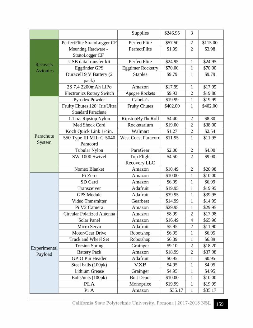
159
Supplies $246.95 3
Recovery Avionics
PerfectFlite StratoLogger CF PerfectFlite $57.50 2 $115.00 Mounting Hardware -
StratoLogger CF PerfectFlite $1.99 2 $3.98
USB data transfer kit PerfectFlite $24.95 1 $24.95 Eggfinder GPS Eggtimer Rocketry $70.00 1 $70.00
Duracell 9 V Battery (2 pack)
Staples $9.79 1 $9.79
2S 7.4 2200mAh LiPo Amazon $17.99 1 $17.99 Electronics Rotary Switch Apogee Rockets $9.93 2 $19.86
Parachute System
Pyrodex Powder Cabela's $19.99 1 $19.99 Fruity Chutes 120" Iris Ultra
Standard Parachute Fruity Chutes $402.00 1 $402.00
1.1 oz. Ripstop Nylon RipstopByTheRoll $4.40 2 $8.80 Med Shock Cord Rocketarium $19.00 2 $38.00
Koch Quick Link 1/4in. Walmart $1.27 2 $2.54 550 Type III MIL-C-5040
Paracord West Coast Paracord $11.95 1 $11.95
Tubular Nylon ParaGear $2.00 2 $4.00 SW-1000 Swivel Top Flight
Recovery LLC $4.50 2 $9.00
Nomex Blanket Amazon $10.49 2 $20.98
Experimental Payload
Pi Zero Amazon $10.00 1 $10.00 SD Card Amazon $6.99 1 $6.99
Transceiver Adafruit $19.95 1 $19.95 GPS Module Adafruit $39.95 1 $39.95
Video Transmitter Gearbest $14.99 1 $14.99 Pi V2 Camera Amazon $29.95 1 $29.95
Circular Polarized Antenna Amazon $8.99 2 $17.98 Solar Panel Amazon $16.49 4 $65.96 Micro Servo Adafruit $5.95 2 $11.90
Motor/Gear Drive Robotshop $6.95 1 $6.95 Track and Wheel Set Robotshop $6.39 1 $6.39
Torsion Spring Grainger $9.10 2 $18.20 Battery Pack Amazon $18.99 2 $37.98
GPIO Pin Header Adafruit $0.95 1 $0.95 Steel balls (100pk) VXB $4.95 1 $4.95
Lithium Grease Grainger $4.95 1 $4.95 Bolts/nuts (100pk) Bolt Depot $10.00 1 $10.00
PLA Monoprice $19.99 1 $19.99 Pi A Amazon $35.17 1 $35.17

160
Transceiver Adafruit $19.95 1 $19.95 Video Receiver Gearbest $14.99 1 $14.99 LCD Screen Amazon $34.95 1 $34.95
Keyboard Walmart $14.95 1 $14.95 Circular Polarized Antenna Amazon $8.99 2 $17.98
Total Expenses $3,007.39
7.3.2 Sub Scale Launch Vehicle Expenses
Table 7.3.2-1: Launch vehicle expenses for the sub-scale model.
Sub-Scale Launch Vehicle Budget
Item
Supplier Unit Price
Qty
Total Price
Vehicle Structure
Blue Tube 2.0 Airframe ARR $29.95 1 $29.95 Blue Tube 2.0 Coupler ARR $31.95 1 $31.95
Eye-bolt Lowes $0.95 4 $3.80
Nylon Shear Pins Apogee Components
$0.00
0 $0.00
PVC pipe Home Depot $0.00 0 $0.00 PLA filament re3D $0.00 0 $0.00
10-32 Alloy Steel Hex Flat Head Screw (100pk)
McMaster carr
$10.65
1
$10.65
10-32 zinc plated nuts McMaster carr $7.78 1 $7.78 3/4'' Birch Plywood Home Depot $49.98 1 $49.98
Propulsion
System
Motor Hardware
siriusrocketry $416.00
1
$416.00
Retainer Sirius Rocketry $47.08 1 $47.08 Lube siriusrocketry $5.99 1 $5.99
Aerotech J460T Apogee Rockets $128 2 $256
Recovery Avionics
PerfectFlite StratoLogger CF PerfectFlite $57.50 2 $115.00 Mounting Hardware -
StratoLogger CF PerfectFlite $1.99 2 $3.98
USB data transfer kit PerfectFlite $24.95 1 $24.95 Eggfinder GPS Eggtimer Rocketry $70.00 1 $70.00
Duracell 9 V Battery (2 pack)
Staples $9.79 1 $9.79
2S 7.4 2200mAh Lipo Amazon $17.99 1 $17.99
Electronics Rotary Switch Apogee Rockets $9.93 2 $19.86
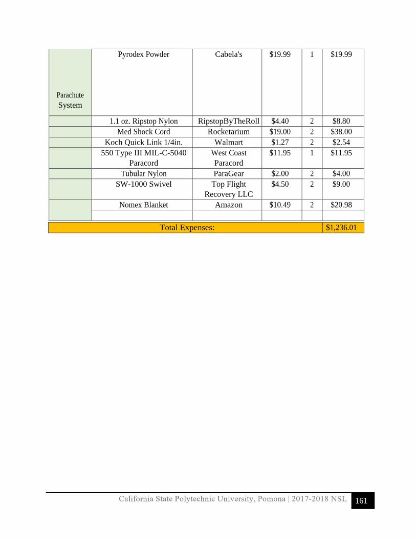
161
Parachute System
Pyrodex Powder Cabela's $19.99 1 $19.99
1.1 oz. Ripstop Nylon RipstopByTheRoll $4.40 2 $8.80 Med Shock Cord Rocketarium $19.00 2 $38.00 Koch Quick Link 1/4in. Walmart $1.27 2 $2.54 550 Type III MIL-C-5040
Paracord West Coast Paracord
$11.95 1 $11.95
Tubular Nylon ParaGear $2.00 2 $4.00 SW-1000 Swivel Top Flight
Recovery LLC $4.50 2 $9.00
Nomex Blanket Amazon $10.49 2 $20.98
Total Expenses: $1,236.01

162
7.3.3 Payload Expense
Table 8.2.4-1: Expenses for the payload experiment.
Payload Experiment Expenses Item Supplier Unit Price Qty Total Price
Rover
Pi Zero Amazon $10.00 1 $10.00 SD Card Amazon $6.99 1 $6.99 Transceiver Adafruit $19.95 1 $19.95 GPS Module Adafruit $39.95 1 $39.95 Video Transmitter Gearbest $14.99 1 $14.99 Pi V2 Camera Amazon $29.95 1 $29.95 Circular Polarized Antenna Amazon $8.99 2 $17.98 Solar Panel Amazon $16.49 4 $65.96 Micro Servo Adafruit $5.95 2 $11.90 Motor/Gear Drive Robotshop $6.95 1 $6.95 Track and Wheel Set Robotshop $6.39 1 $6.39 Torsion Spring Grainger $9.10 2 $18.20 Battery Pack Amazon $18.99 2 $37.98 GPIO Pin Header Adafruit $0.95 1 $0.95
Pendulum (SPOC)
Steel balls (100pk) VXB $4.95 1 $4.95 Lithium Grease Grainger $4.95 1 $4.95 Bolts/nuts (100pk) Bolt Depot $10.00 1 $10.00 PLA Monoprice $19.99 1 $19.99
Ground Station
Pi A Amazon $35.17 1 $35.17 Transceiver Adafruit $19.95 1 $19.95 Video Receiver Gearbest $14.99 1 $14.99 LCD Screen Amazon $34.95 1 $34.95 Keyboard Walmart $14.95 1 $14.95 Circular Polarized Antenna Amazon $8.99 2 $17.98
Total Expenses: $466.02

163
7.3.4 Educational Engagement Expenses
Table 7.3.4-1: Expenses for Educational Outreach
7.3.5 Travel Expenses
Table 7.3.5-1: Expenses for launch site fees for all full-scale and sub-scale launches.
Launch Site Fees (Sub-scale & Full-scale) Item
Supplier
Unit Price
Qty
Total Price
Sub-scale Test #1:
Rocketry Organization of California (ROC) at the Lucerne Dry Lake Launch Site
$20
1
$20
Sub-scale Test #2:
Friends of Amateur Rocketry (FAR) at the Mojave Desert Launch Site
$10
15
$150

164
Sub-scale Test Backup #1: F.A.R. $10 15 $150
Sub-scale Test Backup #2: F.A.R. $10 15 $150
Full-scale Test #1: R.O.C. $20 1 $20
Full-scale Test #2: F.A.R. $10 15 $150
Full-scale Test Backup #1: F.A.R. $10 15 $150
Full-scale Test Backup #2: F.A.R. $10 15 $150
Total Expenses $940
Table 7.3.5-2: Launch site travel expenses from Cal Poly Pomona to the launch sites.
Launch Site Transportation
Item Supplier
Gas Price per Visit (3
vehicles)
Total Visits
Total Gas Price
Roundtrip CPP to the ROC Site
n/a
$76.44
2
$152.88
Roundtrip CPP to the FAR Site
n/a
$148.26
6
$889.56
Total Expenses $1,042
7.3.6 Other Expenses
Table 7.3.6-1: Other expenses including website maintenance and travel to
competition.
Other Expenses Item
Supplier
Unit Price
Qty
Total Price
Website
Starter Site 1 year subscription
Weebly
$96.00
1
$96.00
Domain name for CPP Rocketry website
Weebly
$29.95
1
$29.95
Travel Flight & Hotel (4/4-4/9) Priceline $551
15
$8,265.00
Total Expenses $8,390.95

California State Polytechnic University, Pomona | 2017-2018 NSL
165
7.3.7 Overall Expenses
Table 7.3.7-1: Comprehensive budget including launch vehicles and other expenses.
Overall Budget
Item Total Price Full-Scale Launch Vehicle $3,007.39 Sub-Scale Launch Vehicle $1,236.01 Payload Experiment $466.02 Launch Site Fees $940.00 Launch Site Transportation $1,042.44 Other Expenses $8,390.95 Total Overall Budget $15,082.81
7.3.8 Funding Plan
Plans to acquire funds for the project include: fostering community support, contacting local companies for sponsorship, and attaining University specific grants. The team also partners directly with the high-powered rocketry club, UMBRA, and plans on using its partnership to secure further funding through the team’s University. Some of the main funding sources are outlined in Table 8.3-1 and have not changed since the PDR. Other sources of sponsorship will be used in order to provide for the remaining budget deficit to reach project goals.
Table 7.3.8-1: Funding sources from CPP and Potential Support Funding Source Potential Support Cal Poly Pomona Associated Students Incorporated (ASI) Grant $5,000.00 Cal Poly Pomona Engineering Council Special Projects Funding $800.00 California Space Grant $4,000.00 Cal Poly Pomona Research and Project Grants $1,000.00 Total $10,800

166
7.4 Timeline
7.4.1 Gantt Chart

167

168

169
7.4.2 Important Milestones

170

171

California State Polytechnic University, Pomona | 2017-2018 NSL
172
8.0 Educational Engagement Plan: Status and Summary Originally, four schools are being considered for possible student engagement: International Polytechnic High School (iPoly), Leonard G. Westhoff Elementary School, Suzanne Middle School, and Walnut High School. Due to scheduling conflicts, CPP NSL has come to contact other schools outside of the Pomona and Walnut school districts. An event is planned on Wednesday, January 31 at Cal Poly Pomona. 20 students from Valley Oaks Charter School will come to Cal Poly and listen in on a presentation about our project. Contact with iPoly, Suzanne Middle, Pioneer Middle and Walnut High has been made and outreach events are still pending. Suzanne Middle School wants the Cal Poly Pomona team to give several presentations on the project, particularly in programming, at their multi-purpose room on a Friday in January or February. Details of that event are still being worked out. Responses from the other schools will happen within the upcoming weeks. There are currently four different options of educational engagement with K-12 students. The first option involves an educational/direct interaction where students learn about propulsion and drag. This event will include a lecture and a hands-on activity where the students will use a variety of parachutes and timers to see how different dimensions will affect those two concepts. The second option involves another educational/direct interaction where students will participate in programming exercises at school. We will give a lecture on how programming can bring projects to life and have the students solve real-life applications through coding. At the end of the presentation, we will demonstrate how our payload experiment works with its integration into the launch vehicle by bringing the Raspberry Pi Zero. The third option involves an outreach/direct interaction where the team makes a field trip to the designated school and gives a PowerPoint Presentation about structural components behind the rocket, specifically with the propulsion system and recovery avionics. Towards the end of the presentation, a premade rocket will be launched to showcase the material from the classroom into action. The fourth option involves an outreach/indirect interaction where the team will make a presentation about the overall project and provide an open discussion with students at the end of the presentation.