student guide 195-210 -...
TRANSCRIPT
195
7.1 When to Use 3-D Elements
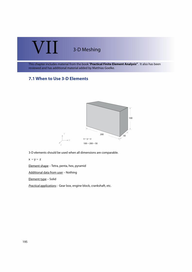
20050
100
x ~ y ~ z
100 ~ 200 ~ 50
Y
X
Z
3-D elements should be used when all dimensions are comparable.
x ~ y ~ z
Element shape – Tetra, penta, hex, pyramid
Additional data from user – Nothing
Element type – Solid
Practical applications : Gear box, engine block, crankshaft, etc.
VII 3-D Meshing
This chapter includes material from the book “Practical Finite Element Analysis”. It also has been
reviewed and has additional material added by Matthias Goelke.
196
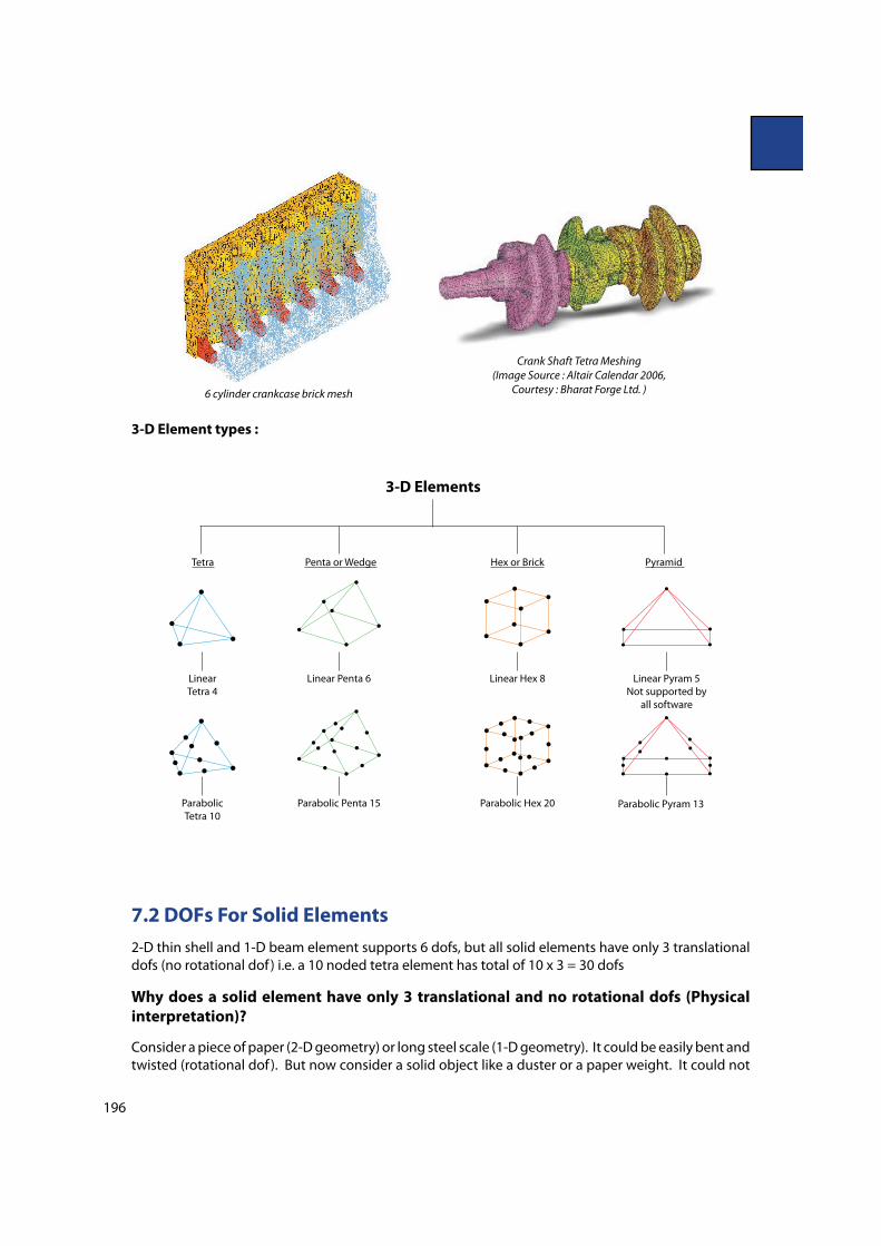
6 cylinder crankcase brick mesh
Crank Shaft Tetra Meshing
(Image Source : Altair Calendar 2006,
Courtesy : Bharat Forge Ltd. )
3-D Element types :
Tetra Penta or Wedge Hex or Brick Pyramid
Linear
Tetra 4
Linear Penta 6 Linear Hex 8
Parabolic
Tetra 10
Parabolic Penta 15 Parabolic Hex 20
Linear Pyram 5
Not supported by
all software
Parabolic Pyram 13
3-D Elements
7.2 DOFs For Solid Elements
2-D thin shell and 1-D beam element supports 6 dofs, but all solid elements have only 3 translational
dofs (no rotational dof ) i.e. a 10 noded tetra element has total of 10 x 3 = 30 dofs
Why does a solid element have only 3 translational and no rotational dofs (Physical
interpretation)?
Consider a piece of paper (2-D geometry) or long steel scale (1-D geometry). It could be easily bent and
twisted (rotational dof ). But now consider a solid object like a duster or a paper weight. It could not
197
be subjected to very high bending or torsion sti!ness. Hence, solid elements have been formulated
with 3 translational dofs and no rotational dofs.
7.3 Tetra Meshing Techniques
There are two methods of tetra meshing.
1) Automatic mesh: This approach is limited to simple geometries and the pre-requisite is an error
free CAD model. The user just has to select the volume and the software automatically carries out the
meshing as per the speci"ed element length, quality criteria, etc.
Advantage: Very quick, no meshing e!orts
Disadvantage: Results in a very high number of nodes and elements. There is no control over the
mesh #ow and the speci"c mesh pattern requirement (like bolted, welded joints or contact surface
simulation).
2) 2-D (Tria) to 3-D (Tetra): This is the most commonly used method. Quad or tria meshing is carried
out on all the outer surfaces of the geometry. During the tetra meshing the quads are automatically
split into trias which then serve as the “basis” of the tetra elements.
Steps for 2-D (Tria) to 3-D (Tetra) mesh generation :
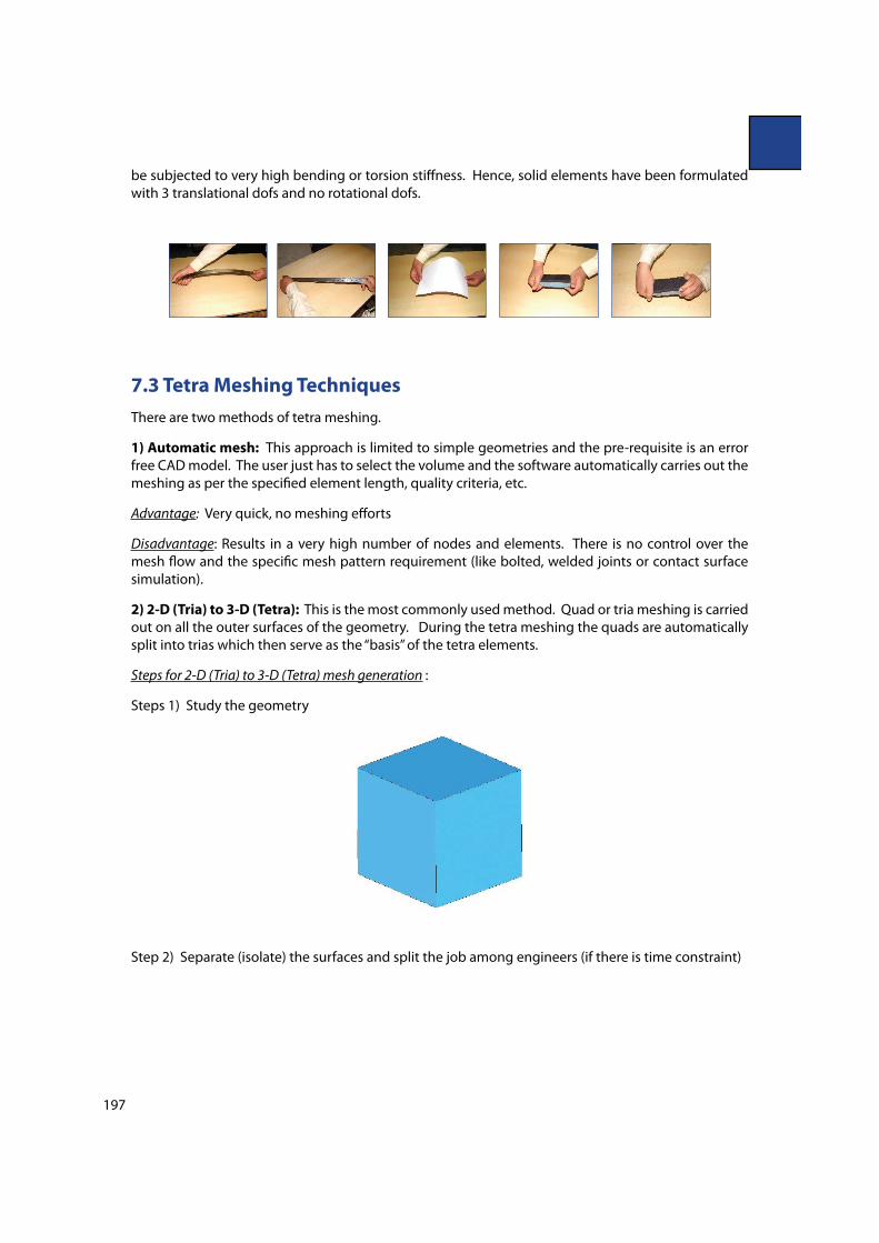
Steps 1) Study the geometry
Step 2) Separate (isolate) the surfaces and split the job among engineers (if there is time constraint)
198
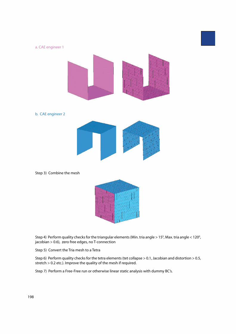
a. CAE engineer 1
b. CAE engineer 2
Step 3) Combine the mesh
Step 4) Perform quality checks for the triangular elements (Min. tria angle > 150, Max. tria angle < 1200,
jacobian > 0.6), zero free edges, no T-connection
Step 5) Convert the Tria mesh to a Tetra
Step 6) Perform quality checks for the tetra elements (tet collapse > 0.1, Jacobian and distortion > 0.5,
stretch > 0.2 etc.). Improve the quality of the mesh if required.
Step 7) Perform a Free-Free run or otherwise linear static analysis with dummy BC’s.
199
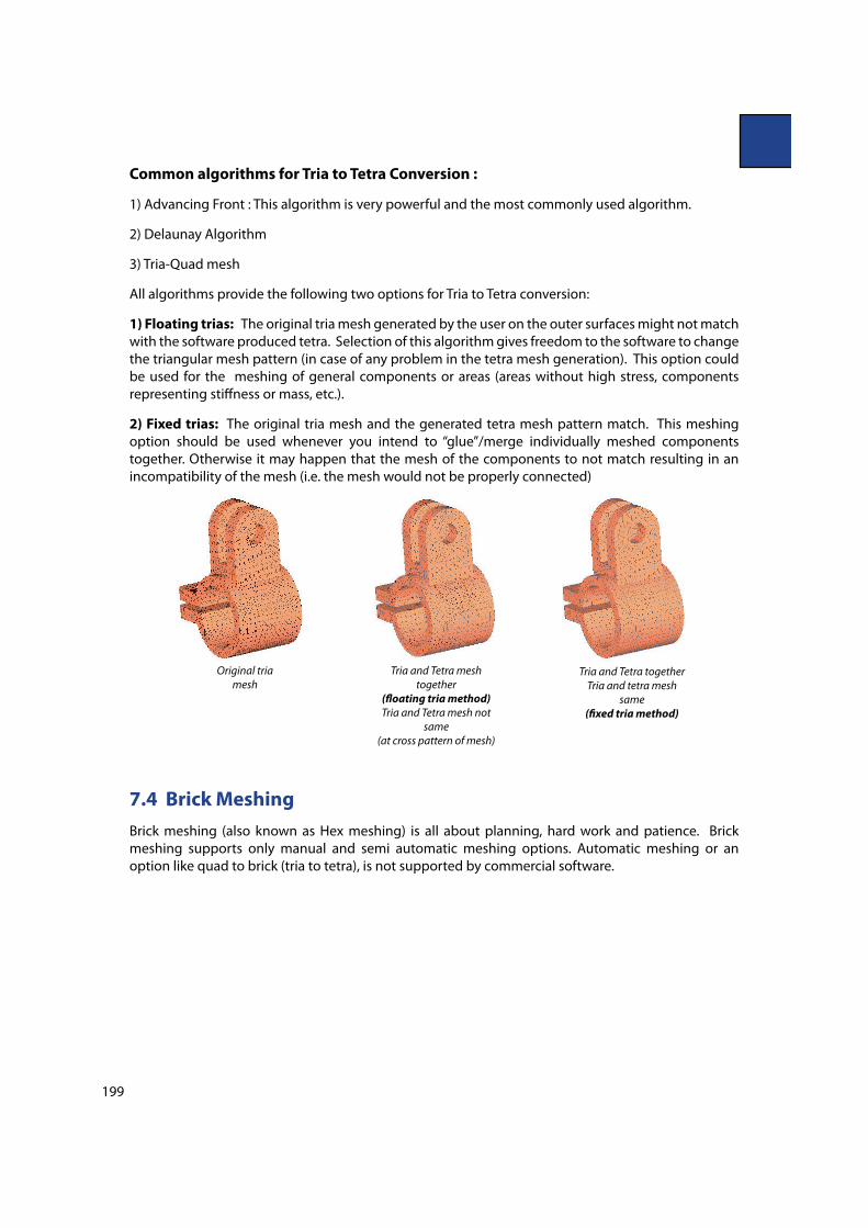
Common algorithms for Tria to Tetra Conversion :
1) Advancing Front : This algorithm is very powerful and the most commonly used algorithm.
2) Delaunay Algorithm
3) Tria-Quad mesh
All algorithms provide the following two options for Tria to Tetra conversion:
1) Floating trias: The original tria mesh generated by the user on the outer surfaces might not match
with the software produced tetra. Selection of this algorithm gives freedom to the software to change
the triangular mesh pattern (in case of any problem in the tetra mesh generation). This option could
be used for the meshing of general components or areas (areas without high stress, components
representing sti!ness or mass, etc.).
2) Fixed trias: The original tria mesh and the generated tetra mesh pattern match. This meshing
option should be used whenever you intend to “glue”/merge individually meshed components
together. Otherwise it may happen that the mesh of the components to not match resulting in an
incompatibility of the mesh (i.e. the mesh would not be properly connected)
Original tria
mesh
Tria and Tetra mesh
together
(�oating tria method)
Tria and Tetra mesh not
same
(at cross pattern of mesh)
Tria and Tetra together
Tria and tetra mesh
same
(!xed tria method)
7.4 Brick Meshing
Brick meshing (also known as Hex meshing) is all about planning, hard work and patience. Brick
meshing supports only manual and semi automatic meshing options. Automatic meshing or an
option like quad to brick (tria to tetra), is not supported by commercial software.
200
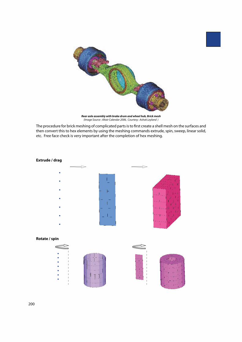
Rear axle assembly with brake drum and wheel hub, Brick mesh
(Image Source : Altair Calendar 2006, Courtesy : Ashok Leyland )
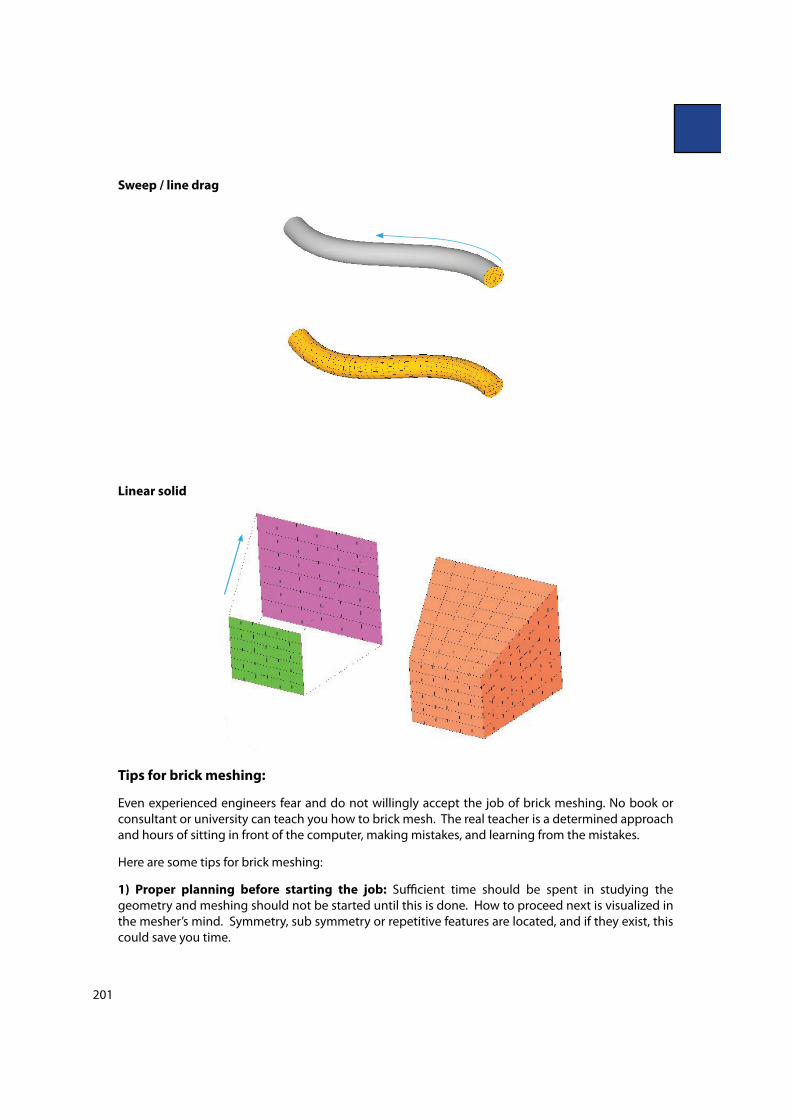
The procedure for brick meshing of complicated parts is to "rst create a shell mesh on the surfaces and
then convert this to hex elements by using the meshing commands extrude, spin, sweep, linear solid,
etc. Free face check is very important after the completion of hex meshing.
Extrude / drag
Rotate / spin
201
Sweep / line drag
Linear solid
Tips for brick meshing:
Even experienced engineers fear and do not willingly accept the job of brick meshing. No book or
consultant or university can teach you how to brick mesh. The real teacher is a determined approach
and hours of sitting in front of the computer, making mistakes, and learning from the mistakes.
Here are some tips for brick meshing:
1) Proper planning before starting the job: Su$cient time should be spent in studying the
geometry and meshing should not be started until this is done. How to proceed next is visualized in
the mesher’s mind. Symmetry, sub symmetry or repetitive features are located, and if they exist, this
could save you time.
202
2) 2-D quad mesh should be systematic (ruled or mapped), avoid 2-D auto mesh: Flow lines
should be maintained with minimum number of trias and diamond or rotating quads should be
avoided. Use of the auto mesher on surfaces sometimes results in a zig-zag or random mesh which
might lead to unexpected problems later.
3) Do not hurry to convert the shell mesh to brick: One should not convert a 2-D mesh to a 3-D
mesh immediately. Instead, proceed further with the quads and checking for any possible problem
with the current pattern is recommended.
4) Start from the most complicated feature and not the simplest one or a corner of the part:
During exams for e!ective time management, the basic thumb rule told to students is to “Attack the
simple problems "rst and then the complicated one.” The thumb rule for brick meshing is exactly
the reverse i.e. “Attack the complicated features "rst and then the simple ones”. Beginners make a
common mistake to mesh the simplest and outer corners of the part "rst.
5) Use the linear solid command: Linear solid and morphing are very powerful commands for brick
meshing and should be utilized.
Brick and Tetra meshing comparison
Vs
The number of elements and nodes generated by a brick mesh are of the order of 1/2 to 1/50
in comparison to a tetra mesh. A brick mesh reduces the solution time and results in the ease
of handling the model on a workstation (pre and post display).
Analysis types like crash or nonlinear give preference to brick mesh due to the number of
nodes and mesh #ow lines.
The time consumed in brick meshing is more and requires experience, hard work, and a lot
of patience too.
Over the years, the algorithm for tetra meshing has improved and accuracy wise there is not
much di!erence in tetra 10 and brick 8 elements.
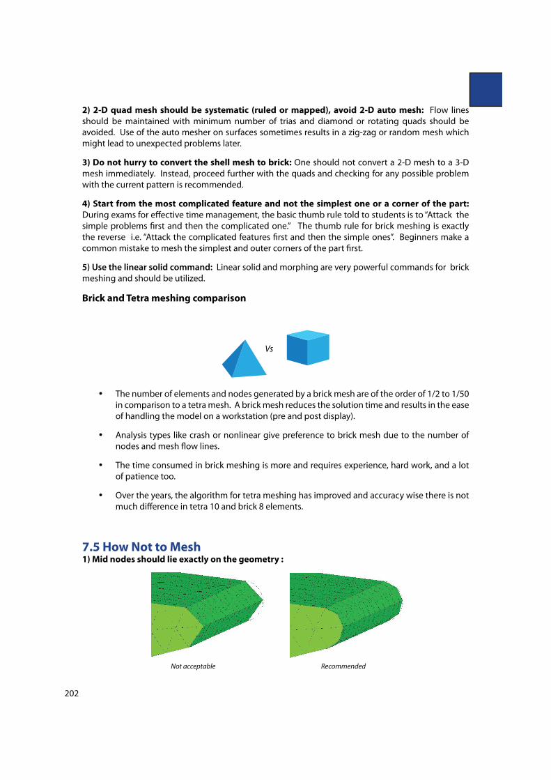
7.5 How Not to Mesh1) Mid nodes should lie exactly on the geometry :
Not acceptable Recommended
203
For a parabolic tetra meshing task, many CAE engineers prefer to start with linear tria (instead of
parabolic) meshing and then covert it to parabolic. In the conversion process, mid nodes might
not get projected automatically on the curved surfaces and "llets. If so, it should be projected on
corresponding surfaces before conversion to tetras.
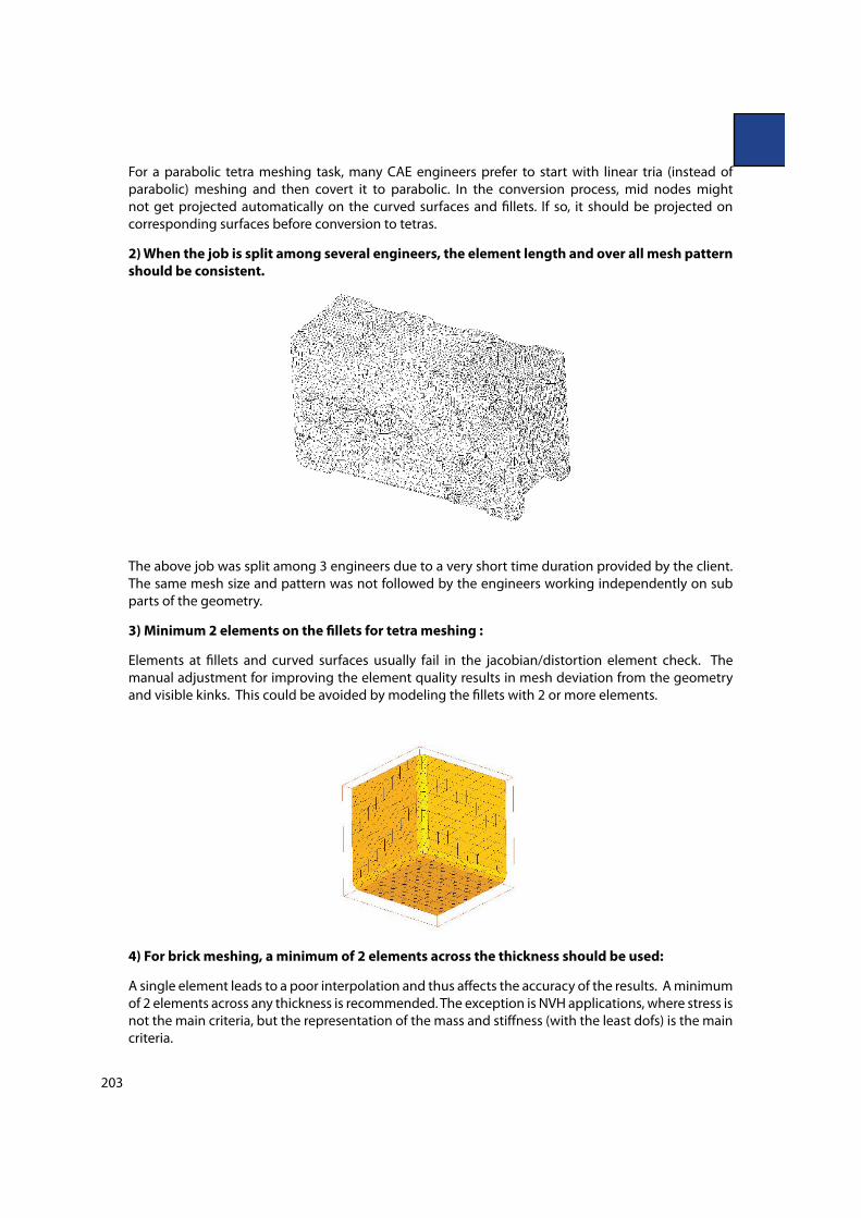
2) When the job is split among several engineers, the element length and over all mesh pattern
should be consistent.
The above job was split among 3 engineers due to a very short time duration provided by the client.
The same mesh size and pattern was not followed by the engineers working independently on sub
parts of the geometry.
3) Minimum 2 elements on the !llets for tetra meshing :
Elements at "llets and curved surfaces usually fail in the jacobian/distortion element check. The
manual adjustment for improving the element quality results in mesh deviation from the geometry
and visible kinks. This could be avoided by modeling the "llets with 2 or more elements.
4) For brick meshing, a minimum of 2 elements across the thickness should be used:
A single element leads to a poor interpolation and thus a!ects the accuracy of the results. A minimum
of 2 elements across any thickness is recommended. The exception is NVH applications, where stress is
not the main criteria, but the representation of the mass and sti!ness (with the least dofs) is the main
criteria.
204
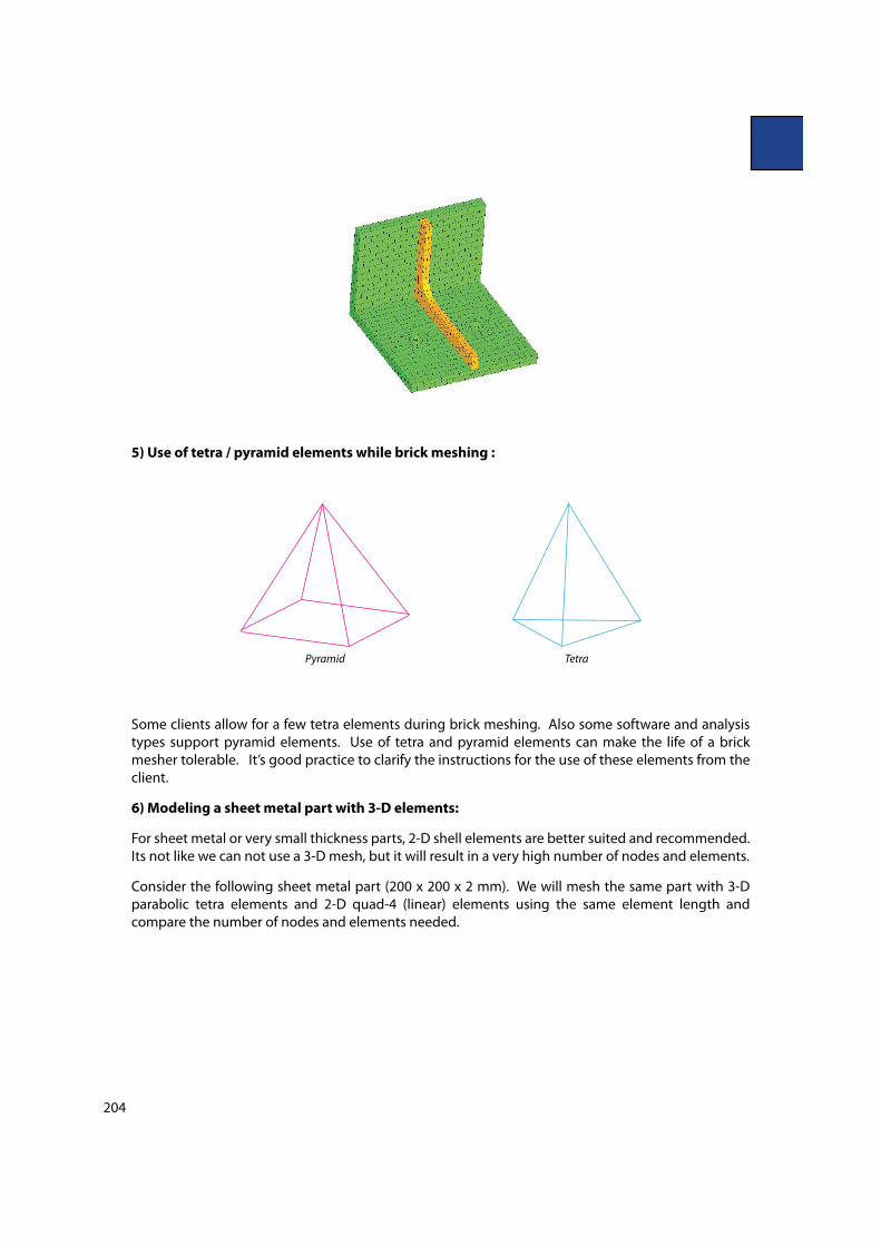
5) Use of tetra / pyramid elements while brick meshing :
Pyramid Tetra
Some clients allow for a few tetra elements during brick meshing. Also some software and analysis
types support pyramid elements. Use of tetra and pyramid elements can make the life of a brick
mesher tolerable. It’s good practice to clarify the instructions for the use of these elements from the
client.
6) Modeling a sheet metal part with 3-D elements:
For sheet metal or very small thickness parts, 2-D shell elements are better suited and recommended.
Its not like we can not use a 3-D mesh, but it will result in a very high number of nodes and elements.
Consider the following sheet metal part (200 x 200 x 2 mm). We will mesh the same part with 3-D
parabolic tetra elements and 2-D quad-4 (linear) elements using the same element length and
compare the number of nodes and elements needed.
205
3-D Tetra mesh
Nodes = 1496
Elements = 689
2-D quad-4 mesh
Nodes = 121
Elements =100
7) Limitation of 1-D element and advantage of 3-D meshing:
Fillets, cutouts and complicated geometry features cannot be represented accurately by 1-D elements.
3-D elements, because of 3 dimensions, can capture all the minute details accurately. For example,
consider the following shaft. It is very di$cult to capture the key way slot and variable "llet using 1-D
elements. Instead 3-D meshing is recommended for such applications.
7.8 Creating 3-D Elements using HyperMesh
HyperMesh can be used to generate a tetra mesh or a brick mesh. Below is an explanation on how
to perform both types of meshing.
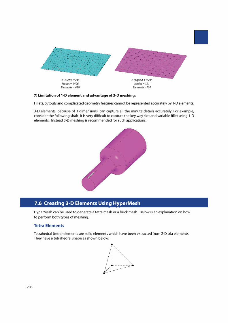
Tetra Elements
Tetrahedral (tetra) elements are solid elements which have been extracted from 2-D tria elements.
They have a tetrahedral shape as shown below:
7.6 Creating 3-D Elements Using HyperMesh
206
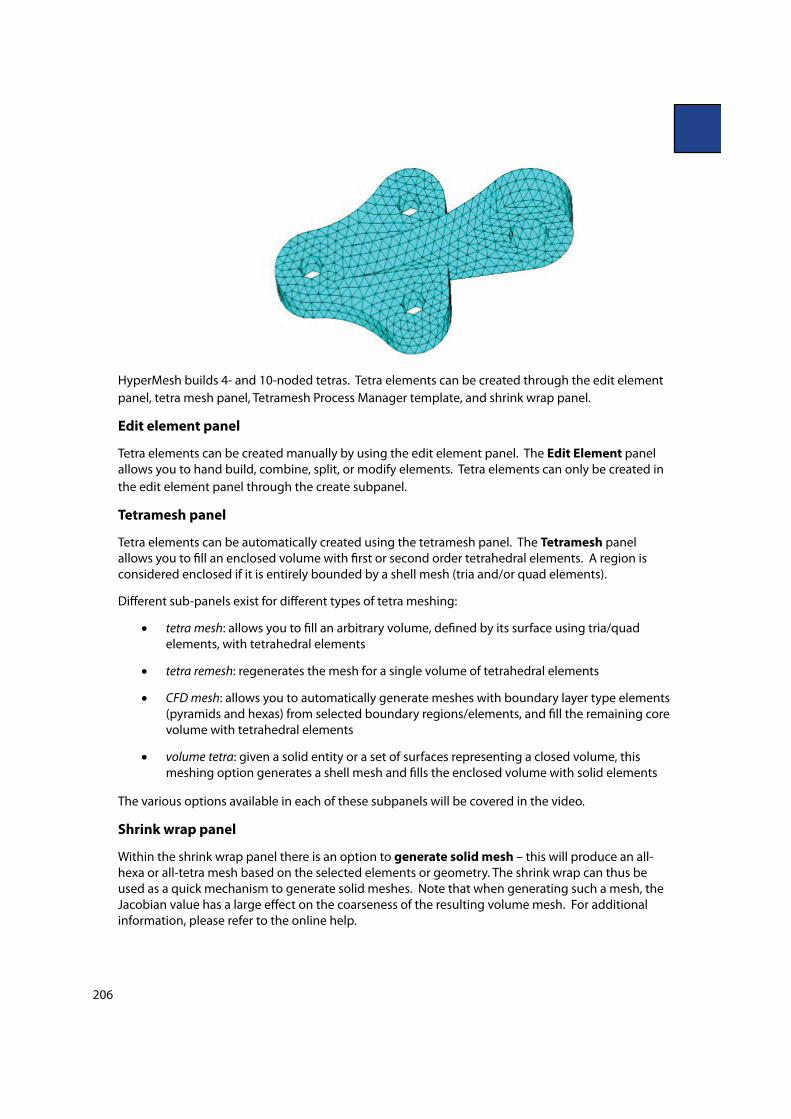
HyperMesh builds 4- and 10-noded tetras. Tetra elements can be created through the edit element
panel, tetra mesh panel, Tetramesh Process Manager template, and shrink wrap panel.
Edit element panel
Tetra elements can be created manually by using the edit element panel. The Edit Element panel
allows you to hand build, combine, split, or modify elements. Tetra elements can only be created in
the edit element panel through the create subpanel.
Tetramesh panel
Tetra elements can be automatically created using the tetramesh panel. The Tetramesh panel
allows you to "ll an enclosed volume with "rst or second order tetrahedral elements. A region is
considered enclosed if it is entirely bounded by a shell mesh (tria and/or quad elements).
Di!erent sub-panels exist for di!erent types of tetra meshing:
tetra mesh: allows you to "ll an arbitrary volume, de"ned by its surface using tria/quad
elements, with tetrahedral elements
tetra remesh: regenerates the mesh for a single volume of tetrahedral elements
CFD mesh: allows you to automatically generate meshes with boundary layer type elements
(pyramids and hexas) from selected boundary regions/elements, and "ll the remaining core
volume with tetrahedral elements
volume tetra: given a solid entity or a set of surfaces representing a closed volume, this
meshing option generates a shell mesh and "lls the enclosed volume with solid elements
The various options available in each of these subpanels will be covered in the video.
Shrink wrap panel
Within the shrink wrap panel there is an option to generate solid mesh – this will produce an all-
hexa or all-tetra mesh based on the selected elements or geometry. The shrink wrap can thus be
used as a quick mechanism to generate solid meshes. Note that when generating such a mesh, the
Jacobian value has a large e!ect on the coarseness of the resulting volume mesh. For additional
information, please refer to the online help.
207
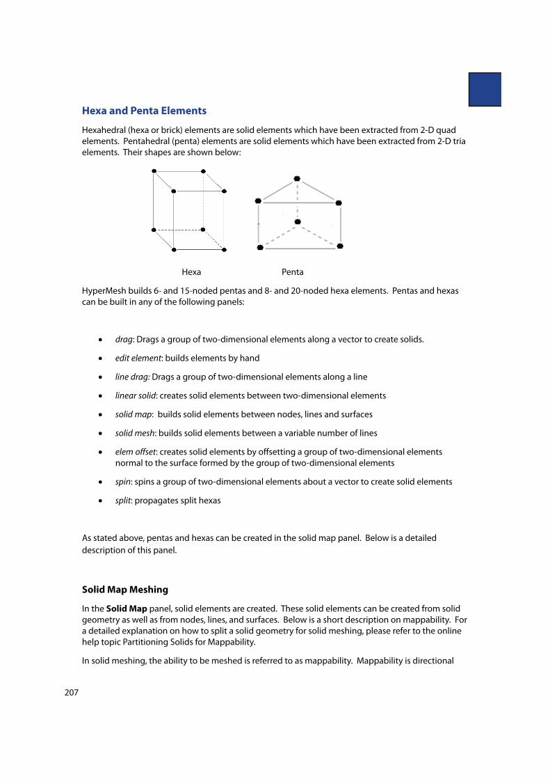
Hexa and Penta Elements
Hexahedral (hexa or brick) elements are solid elements which have been extracted from 2-D quad
elements. Pentahedral (penta) elements are solid elements which have been extracted from 2-D tria
elements. Their shapes are shown below:
Hexa Penta
HyperMesh builds 6- and 15-noded pentas and 8- and 20-noded hexa elements. Pentas and hexas
can be built in any of the following panels:
drag: Drags a group of two-dimensional elements along a vector to create solids.
edit element: builds elements by hand
line drag: Drags a group of two-dimensional elements along a line
linear solid: creates solid elements between two-dimensional elements
solid map: builds solid elements between nodes, lines and surfaces
solid mesh: builds solid elements between a variable number of lines
elem o!set: creates solid elements by o!setting a group of two-dimensional elements
normal to the surface formed by the group of two-dimensional elements
spin: spins a group of two-dimensional elements about a vector to create solid elements
split: propagates split hexas
As stated above, pentas and hexas can be created in the solid map panel. Below is a detailed
description of this panel.
Solid Map Meshing
In the Solid Map panel, solid elements are created. These solid elements can be created from solid
geometry as well as from nodes, lines, and surfaces. Below is a short description on mappability. For
a detailed explanation on how to split a solid geometry for solid meshing, please refer to the online
help topic Partitioning Solids for Mappability.
In solid meshing, the ability to be meshed is referred to as mappability. Mappability is directional
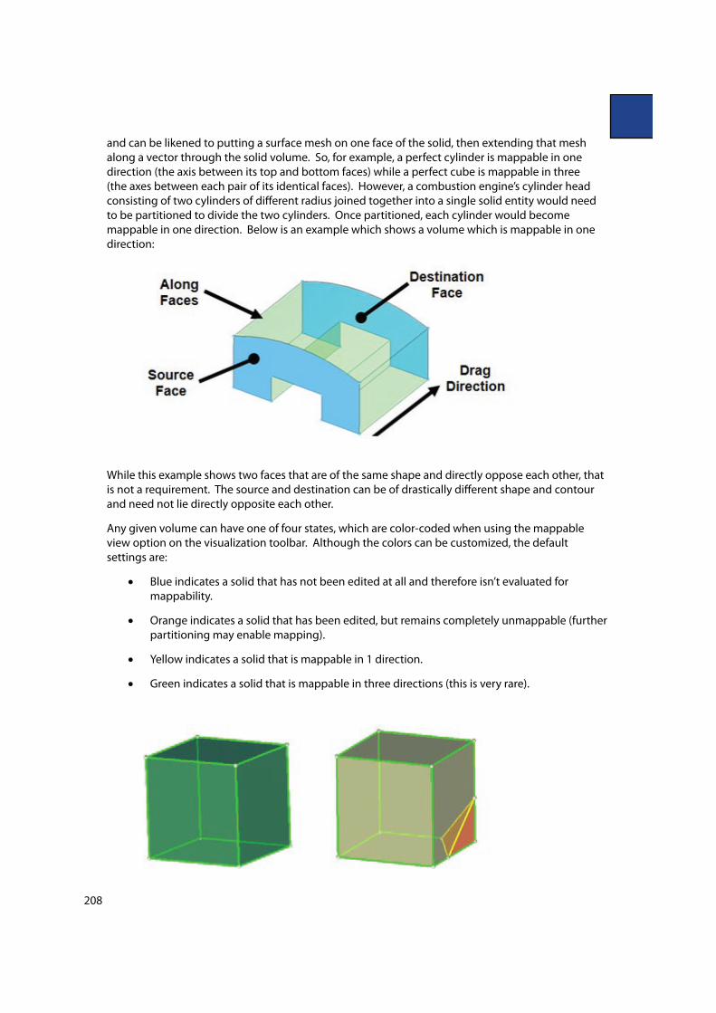
208
and can be likened to putting a surface mesh on one face of the solid, then extending that mesh
along a vector through the solid volume. So, for example, a perfect cylinder is mappable in one
direction (the axis between its top and bottom faces) while a perfect cube is mappable in three
(the axes between each pair of its identical faces). However, a combustion engine’s cylinder head
consisting of two cylinders of di!erent radius joined together into a single solid entity would need
to be partitioned to divide the two cylinders. Once partitioned, each cylinder would become
mappable in one direction. Below is an example which shows a volume which is mappable in one
direction:
While this example shows two faces that are of the same shape and directly oppose each other, that
is not a requirement. The source and destination can be of drastically di!erent shape and contour
and need not lie directly opposite each other.
Any given volume can have one of four states, which are color-coded when using the mappable
view option on the visualization toolbar. Although the colors can be customized, the default
settings are:
Blue indicates a solid that has not been edited at all and therefore isn’t evaluated for
mappability.
Orange indicates a solid that has been edited, but remains completely unmappable (further
partitioning may enable mapping).
Yellow indicates a solid that is mappable in 1 direction.
Green indicates a solid that is mappable in three directions (this is very rare).
209
In the images above, the "rst cube is mappable in 3 directions. The second image shows that if a
corner is split o!, it becomes mappable in only 1 direction and the corner is not mappable without
further partitioning.
The Solid Map panel for is used for solid-map meshing, and this panel includes several sub-
panels. The general, line drag, linear solid, and ends only sub-panels all draw from the same set
of input controls (the more specialized panels simply "lter out the controls that do not apply to their
mapping techniques). Note that all of these sub-panels depend on an existing 2-D mesh, which is
then extrapolated into a 3-D mesh based on the parameters you input. The one volume and multi
solids sub-panels, however, can automatically create 3-D mesh directly on solids as long as the
solids you select are already mappable.
Solid map panel:
general: Use the general sub-panel to access all of the possible entry controls for maximum
#exibility.
line drag: Use the line drag sub-panel to select a 2-D mesh, and then select a line from the
model geometry to use as the mapping direction.
linear solid: Use the linear solid sub-panel to select two existing 2-D meshes and extrapolate
a 3-D mesh that connects them.
ends only: Use the ends only sub-panel to select two opposing surfaces and one 2-D mesh,
then extrapolate the mesh between the surfaces.
one volume: Use the one volume sub-panel to select a single mappable solid volume and
create a new 3-D mesh for it.
multi solids: Use the multi solids sub-panel to select multiple mappable solids and create
3-D meshes for them.
7.9 Tutorials/Interactive Videos/etc on 3-D Meshing
To view the following videos and tutorials, you "rst need to register at the HyperWorks Client Center
using your university E-Mail address. Once you have a password, log into the Client Center and then
access the videos and tutorials using the links below.
Recommended Tutorials:
These tutorials can be accessed within the installation inside the Help Document.:
From the menu bar select Help > HyperWorks Desktop > Tutorials > HyperWorks Tutorials >
HyperWorks Desktop > HyperMesh > Meshing > 3-D Elements
Tutorials can also be accessed within the Online Help which can be accessed using the links below.
You will need to log into the HyperWorks Client Center to access these tutorials online.
HM-3200: Tetrameshing
HM-3210: Creating a Hex-Penta Mesh using Surfaces
HM-3220: Creating a Hexahedral Mesh using the Solid Map Function
7.7 3-D Meshing Tutorials and Interactive Videos
210
HM-3270: Using the TetraMesh Process Manager
Recommended Videos
Webinar
Meshing Webinar
Product Videos (10-15 minute; no HyperWorks installation required)
Solid Map Mesh Enhancements
Tetra meshing a Piston
Solid Geometry & Hexa-meshing
8.0 video, if we use it, it needs to be updated
Meshing Tutorial
Solid Meshing with HyperMesh
Multiple Solids Meshing with HyperMesh
HyperMesh - Creating Mesh for Casting Simulation
Interactive Tutorial Videos (no HyperWorks installation required)
HM-3200 Tetrameshing
Demo Files
Tetra Meshing - Engine Cylinder Head
Crane Hexa Meshing
Transfercase Tetra Meshing
Aircraft Engine Component Tetra Meshing
Rib Creation