structured safety case tools for nuclear facility automation · ii tiivistelmÄ linnosmaa, joonas:...
TRANSCRIPT

JOONAS LINNOSMAA
STRUCTURED SAFETY CASE TOOLS FOR NUCLEAR FACILITY
AUTOMATION
Master of Science Thesis
Examiner: Jouni Kivistö-Rahnasto Examiner and topic approved in the Natural Sciences Faculty Council meeting on 9th December 2015
i
ABSTRACT
LINNOSMAA, JOONAS: Structured safety case tools for nuclear facility auto-mation Tampere University of Technology Master’s Degree Programme in Environmental and Energy Technology Master of Science Thesis, 68 pages April 2016 Major: Occupational Safety Engineering Examiner: Professor Jouni Kivistö-Rahnasto Keywords: safety case, assurance case, instrumentation & control systems, automation, safety justification, nuclear power plant, licensing, qualification, safety case tools
In regulated domains, such as nuclear power, a documented justification of safety is
demanded for licensing and qualifying systems important to safety. One emerging way
of communicating the safety of a complex system in a structured and comprehensive
manner is using a safety case. Safety case is understood as a documented body of evi-
dence that provides a convincing and a valid argument that a system is adequately safe
for a given application in a given environment. It is one option to give the safety justifi-
cation the transparency and traceability required by the stakeholders. Because of the
amount and complexity of the required material, a practical way of preparing safety
cases is to use a software tool. This thesis evaluated software tools for developing a
structured safety case for nuclear instrumentation and control systems justification.
For tool evaluation, a set of criteria was done derived from a description of the tool us-
age environment in the nuclear domain. There is unestablished terminology in the do-
main and the description gives some clarification to the concepts. Main terms were nu-
clear safety case, safety demonstration and structured safety case. Nuclear safety case
was defined as an informal overall term referring to the totality of the safety justification
and management material gathered under one ‘case’. Safety demonstration was defined
as the part of nuclear safety case, which contains the argumentation connecting the rele-
vant evidence to given safety claims. Structured safety case was defined as a safety
demonstration following a presentation of well-defined notation and related standards. It
presents the claims, arguments and evidences required to assure the safety of the given
system clearly and unambiguously. A development process for the structured safety
case was outlined, from which the criteria for planning, structure, data inserting, review
and management features were identified for tool evaluation.
A list of safety case tools was gathered from which five tools were selected for further
study: Astah GSN, ASCE, NOR-STA, ACEdit and D-case Editor. As a result of the tool
review, it was concluded that none of the selected tools had good support for the identi-
fied requirements. All of the tools had some good features for structure and data insert-
ing. Most lack of support was identified among the features relating to planning, manag-
ing and reviewing the safety case. All of the tools also had difficulties with handling the
presentation of large systems. Results implicated that the reviewed safety case software
tools are not yet ready for large scale industrial use for the justification of instrumenta-
tion and control nuclear power plants. For further actions it was recommended to follow
the development and continue testing of the current and new software tools.

ii
TIIVISTELMÄ
LINNOSMAA, JOONAS: Structured safety case tools for nuclear facility auto-mation Tampereen teknillinen yliopisto Ympäristö- ja energiatekniikan diplomi-insinöörin tutkinto-ohjelma Diplomityö, 68 sivua Huhtikuu 2016 Pääaine: Turvallisuustekniikka Tarkastaja: professori Jouni Kivistö-Rahnasto Avainsanat: safety case -menetelmä, safety case työkalu, automaatio, ydinvoi-mala, turvallisuusperustelu, lisensointi, kelpoistus
Viranomaisten valvomilla toimialoilla, kuten ydinvoimassa, turvallisuudelle tärkeiden
järjestelmien lisensointiin ja kelpoistukseen vaaditaan riittävän turvallisuuden osoittava
kirjallinen dokumentaatio. Eräs yleistyvä tapa osoittaa monimutkaisten järjestelmien
turvallisuutta rakenteellisella ja selkeällä tavalla on käyttää siihen safety case -
menetelmää. Safety case sisältää argumentaation ja evidenssin sille, että järjestelmä on
riittävän turvallinen suunniteltuun käyttötarkoitukseen ja -ympäristöön. Safety case on
eräs keino parantaa turvallisuusperustelun jäljitettävyyttä ja avoimuutta. Tarvittavan
materiaalin määrän ja monimutkaisuuden takia safety casen tekemisen apuna on hyödyl-
listä käyttää ohjelmistotyökalua. Tässä työssä arvioitiin sopivia työkaluohjelmia safety
casen tekemiseen ydinvoima-automaation turvallisuusperustelulle.
Työkaluilta vaadittavat ominaisuudet selvitettiin työkaluarvioinnin suorittamiseksi.
Työkaluvaatimusten taustaksi kuvattiin työkalun käyttöympäristöä ydinvoima-alalla.
Terminologia alalla on yhä vakiintumatonta, joten käyttöympäristön keskeiset käsitteet
’nuclear safety case’, ’safety demonstration’ ja ’structured safety case’ yrittävät tuoda
siihen selvyyttä. Nuclear safety case on terminä kokonaisuudelle, joka käsittää kaiken
turvallisuuden osoittamiseen ja hallintaan liittyvän materiaalin. Safety demonstration on
nuclear safety casen osa, joka sisältää turvallisuuden perusteluun liittyvän keskeisen
argumentaation. Argumentaation tarkoituksena on yhdistää kerätty evidenssi järjestel-
mälle annettuihin turvallisuusväittämiin. Structured safety case määriteltiin eräänä safe-
ty demonstrationin strukturoituna esitysmuotona, joka seuraa määriteltyä esitystapaa ja
asiaan liittyviä standardeja. Myös structured safety caseen liittyvä kehitysprosessi luon-
nosteltiin pääpiirteittäin, josta tunnistettiin suunnitteluun, struktuuriin, datan lisäykseen,
arvioimiseen ja työkalun hallintaan liittyvät ominaisuusluokat.
Tarjolla olevista safety case työkaluista koottiin lista, josta viisi työkalua valittiin tar-
kempaan arviointiin: Astah GSN, ASCE, NOR-STA, ACEdit ja D-case Editor. Arvi-
oinnista selvisi, ettei yksikään työkaluista täyttänyt hyvällä tasolla kaikkia asetettuja
vaatimuksia. Kussakin työkalussa tunnistettiin hyviä ja hyödyllisiä ominaisuuksia eri-
tyisesti struktuuriin ja datan lisäykseen liittyen, mutta mikään niistä ei ollut kokonaisuu-
tena riittävän kattava. Isoimmat puutteet olivat suunnittelu-, hallinta- ja arviointitoimin-
noissa, sekä kyvyssä käsitellä laajoja ja monimutkaisia järjestelmiä. Tulokset osoittivat,
etteivät tarkastellut työkalut ole vielä valmiina safety casen laajamittaiseen käyttämi-
seen ydinvoima-automaation turvallisuusperustelussa. Jatkotoimenpide-ehdotuksena
esitetään ohjelmistopohjaisten työkalujen kehittymisen seurantaa ja uusien löydettyjen
työkalujen testausta.

iii
PREFACE
This thesis was done for VTT Technical Research Centre of Finland Ltd, which is a
non-profit multidisciplinary research and development organisation. The work was car-
ried out in Systems modelling and simulation team, starting in June 2015 and finished in
April 2016.The work was done in cooperation with VTT’s other ongoing projects in
particular the SAFIR2018 programme (The Finnish research programme on nuclear
power plant safety 2015-2018), and its project package named SAUNA (Integrated
safety assessment and justification of nuclear power plant automation) relating to as-
sessment and justification of nuclear automation.
I would like to thank my Teemu Tommila from VTT for his invaluable help and
knowledge of the subject during the writing of this thesis. My gratitude also goes to
Jarmo Alanen and Janne Valkonen from VTT for their aid and insight through the pro-
ject. Also thanks to team leader Juha Kortelainen from VTT for providing me the
chance to work on this project. From Tampere University of Technology I would like to
thank my examiner professor Jouni Kivistö-Rahnasto for his guidance.
Finally I want to thank my family, relatives and friends for their support during the
years of studying.
Tampere, April 20, 2016
Joonas Linnosmaa
iv
CONTENT
1. INTRODUCTION .................................................................................................... 1
1.1 Background .................................................................................................... 1
1.2 Goal and scope of this thesis .......................................................................... 2
1.3 Structure of this thesis .................................................................................... 3
2. BACKGROUND ...................................................................................................... 4
2.1 Safety case ...................................................................................................... 4
2.1.1 Introduction to safety cases .............................................................. 4
2.1.2 Assembling a safety case ................................................................. 6
2.1.3 Presenting a safety case .................................................................... 9
2.1.4 Important literature ........................................................................ 14
2.2 Nuclear power plant ..................................................................................... 15
2.2.1 Nuclear power plants and instrumentation & control systems ...... 15
2.2.2 Life cycle and the safety of nuclear power plant ........................... 17
2.3 Nuclear regulation in Finland ....................................................................... 20
2.3.1 Legislation and safety authority ..................................................... 20
2.3.2 Licensing and the required documents ........................................... 22
2.3.3 I&C safety and qualification .......................................................... 23
3. EXECUTION OF RESEARCH .............................................................................. 25
4. RESULTS ............................................................................................................... 27
4.1 Nuclear safety case ....................................................................................... 27
4.2 Development process ................................................................................... 29
4.3 Tool requirements ........................................................................................ 34
4.4 Tool selection ............................................................................................... 36
4.5 Tool review .................................................................................................. 38
4.5.1 Astah GSN ..................................................................................... 38
4.5.2 ASCE ............................................................................................. 40
4.5.3 NOR-STA ...................................................................................... 43
4.5.4 D-case Editor and ACEdit.............................................................. 48
5. DISCUSSION ......................................................................................................... 52
5.1 Analysis of the findings................................................................................ 52
5.2 Conclusions from the review........................................................................ 55
5.3 About safety cases and tools ........................................................................ 57
5.4 Validity and reliability of the results ............................................................ 58
5.5 Implications .................................................................................................. 60
6. CONCLUSIONS ..................................................................................................... 61
REFERENCES ................................................................................................................ 63

v
TERMS AND ABBREVIATION
CAE Claim Argument Evidence
DiD Defence in Depth
GSN Goal Structuring Notation
IAEA International Atomic Energy Agency
I&C Instrumentation and Control
NPP Nuclear Power Plant
OS Operating System
SACM Structured Assurance Case Metamodel
STUK Radiation and Nuclear Authority
TSO Technical Support Organization
UI User Interface
UML Unified Modelling Language
URL Uniform Resource Locator
VTT Technical Research Centre of Finland Ltd
V&V Verification and Validation
XML Extensible Markup Language

1
1. INTRODUCTION
1.1 Background
International safety standards and regulations demand that complex man-made systems,
for example nuclear power plants, are designed, constructed, operated, maintained and
decommissioned according to all the relevant safety requirements. In order to convince
the regulating authorities, the fulfilment of these requirements must be ensured and
demonstrated in unarguable, unbiased, comprehensive and transparent way. In regulated
domains, such as nuclear facilities, a documented justification of safety is demanded for
licencing and qualifying systems. Not only the authorities, but also the system develop-
ers and the owners of the facilities, should be convinced that the safety of the system is
at acceptable level. Challenges of building the required confidence is present at all engi-
neering disciplines, but especially in qualifying digital instrumentation and control sys-
tems. (Valkonen et al. 2016).
Current safety justification practices in complex projects in regulated areas produce a
considerable number of documents, which need to be reviewed and evaluated. There has
been an increasing demand for introducing more structured and transparent way of justi-
fying the safety of a complex system. With prescriptive regulations and standards, the
importance of safety arguments can easily disappear in the sheer number of documents.
In such cases, many pages of supporting evidence are often presented, for example suit-
ability analysis, quality plans or safety assessments, but little may be done to explain
how this evidence relates to the required safety objectives. One approach for demon-
strating the compliance to regulations, is explaining through structured argumentation
how the provided evidence documents relate to the safety claims (see Figure 1). Thus,
an emerging trend in many safety critical areas is doing the justification by using a safe-
ty case as a way to justify the safety of a system or process (Kelly & Weaver 2004).
ArgumentClaim
Evidence
Sub-claim
Evidence
Argument Evidence
Figure 1. Claims, arguments, evidence structure.
2
Safety case is a way of representing all the required information for claiming the safety
of system-of-interest in an explicit and legible manner by using comprehensive argu-
ments supported by credible and traceable evidence. It also presents the possibility of
breaking the top-claim into series of sub-claims with more system or component specif-
ic requirements and evidence relating to them. Information required for justifying the
safety is often captured in a structured graphical or textual format following the struc-
ture above. This will help all relevant stakeholders to follow the reasoning behind
claims and arguments, and tracing them to provided supporting evidence artefacts, even
without a perfect knowledge of the system in question. Both the argument and evidence
are important elements of the safety case that must go hand-in-hand. Argument without
supporting evidence is unfounded and unconvincing, and evidence without argument is
unexplained.
1.2 Goal and scope of this thesis
Demonstrating the safety of complex systems is difficult. For gaining the required con-
fidence, different methods of analysis have to be combined in a systematic and transpar-
ent way. Current practices for doing this in the nuclear domain could hopefully be im-
proved by bringing more structure to safety demonstration documentation and argumen-
tation. Potential applications are interesting for the nuclear power companies, regulators
and support organisations (like VTT). Because safety demonstration requires a consid-
erable number of materials, preparing and maintaining it needs the help of software
tools and relating standards. Luckily, software tools for this exist. As a research organi-
sation working in the nuclear domain, including the automation, VTT is interested
whether these tools would be suitable and ready to be used by power companies, suppli-
er organisations or support organisations offering independent assessments.
The purpose of this thesis is to evaluate practical software tool options for the develop-
ment of a safety case for of nuclear facility automation. The evaluation is done with an
assumption that a safety case would be a viable option for increasing structure, transpar-
ency and traceability of the safety justification work done by nuclear domain stakehold-
ers. For determining the tools suitable for the purpose, evaluation criteria are needed, as
well as defining the idea of how to apply the safety case concept to nuclear domain.
Consequently, the research goal can be divided into four sub goals:
Describe safety case and terminology in the context.
Outline a development process for a safety case.
Define requirements for the tool features.
Evaluate the tools against the requirements.
The study was done in the context of developing a safety case for qualifying Finnish
nuclear power plant instrumentation and control (I&C) systems or components. The
same context can be applied to other complex safety critical fields as well, especially

3
those with programmable I&C. The requirements and the development process of safety
case take place among the stakeholders of licensing of Finnish nuclear power plants and
their instrumentation and control systems.
1.3 Structure of this thesis
The rest of thesis is structured as follows. First is Chapter 2, which contains basic back-
ground information for gaining general understanding about safety cases, their devel-
opment process and documentation. Also, as the context of this thesis was applying the
safety case for nuclear automation, it also introduces some essential information about
nuclear power plants and their instrumentation and control systems. For the require-
ments part, the chapter also goes lightly through the Finnish nuclear energy regulations
and the licensing process of nuclear power plants. In addition, it presents some stand-
ards and other relevant publications in the field.
In Chapter 3, the methods for answering the research questions are explained and the
work flow of thesis is presented. Results of the study are presented in Chapter 4, which
is divided to answer all the sub goals. It contains the relevant background for the tool
evaluation, starting from the description for getting the tool requirements and then mov-
ing to tool search and finally to tool review. Analysis of the results and conclusions are
presented in Chapter 5, which also contains discussion about the validity and the relia-
bility of the results achieved, as well as their implications. Finally, the Chapter 6 gathers
the main results of this study.

4
2. BACKGROUND
2.1 Safety case
2.1.1 Introduction to safety cases
Safety cases have been used around the world in different industries during the last few
decades, such as aviation, the automotive, railways, medical devices, space and nuclear.
As safety critical systems are getting increasingly complex and the safety requirements
are becoming more stringent, interest towards using structured safety cases has been
growing. Over the recent years, the responsibility for ensuring systems safety has shift-
ed to the developers and operators who are required to construct and present well-
reasoned claims, arguments and evidence that their systems achieve acceptable levels of
safety. These arguments with supporting evidence are typically referred to just as safety
case. (Kelly & Weaver 2004). Different related literature, in general, often uses the
terms safety case, assurance case, and safety demonstration as synonyms, without
clearly specifying the differences behind each term. Understanding the difference be-
tween the terms is very much dependent on the source and context. In this thesis Chap-
ter 2 will discuss these terms more freely, like in the sources it is leaning on. In the oth-
er chapters, they will have a more defined meaning. Chapter 4 will define the terms
structured safety case, safety demonstration and nuclear safety case for the use of this
thesis. However, from now on, in this chapter, safety case or assurance case terms are
used.
The confusion with terminology becomes clear, when comparing different definitions
for safety cases given by various organizations and people working with system safety.
Safety case can be defined as: “A documented body of evidence that provides a convinc-
ing and a valid argument that a system is adequately safe for a given application in a
given environment.” (Adelard 2004). This definition is given by Adelard, a British
company working with safety cases and safety case tools since 1987. Same definition is
given by United Kingdom’s Ministry of Defence’s Defence Standard 00-56 Safety
Management Requirements for Defence Systems (Defence Standard 00-56). Other defi-
nition is given by a recent Object Management Group’s Structured Assurance Case
Metamodel SACM: “Assurance case is a set of auditable claims, arguments, and evi-
dence created to support the claim that defined system/service will satisfy the particular
requirements.” (SACM 2015). As explained above the terms assurance case and safety
case are used in literature as having more or less the same meaning. More specifically,
they can be thought as a same method just focusing on different aspects of argumenta-

5
tion. One can also build a case focusing on security, usability or so on, and the name
can be changed accordingly. Yet another definition of a safety cases is given by Profes-
sor Tim Kelly from University of York: “A safety case should communicate a clear,
comprehensive and defensible argument that a system is acceptably safe to operate in a
particular context.”(Kelly 1998). To add confusion, safety demonstration is also given
the same definition by Common Position (2014) and Elforsk Safety Demonstration Plan
Guide (2013) as: “The set of arguments and evidence elements which support a selected
set of claims on the safety of the operation of a system important to safety used in a giv-
en plant environment.”. These were just a few examples of the definitions given for the
safety case during the years. Clearly it can be seen, that clarification to the terms is re-
quired.
As was explained above, there are several different definitions for safety cases, but in
the end, they all try to say the same thing: it’s an attempt or method trying to provide
means to structure the reasoning that engineers use implicitly to gain confidence that
systems will work as expected (Software Engineering Institute 2015). Especially the
introduction of software based digital instrumentation and control systems, for the use
in nuclear power plants, has raised many issues in safety and economics. One increas-
ingly important issue is the need for engineering solutions to support the effective as-
sessment of software based instrumentation and control (I&C) systems. (IAEA 2002).
To discuss safety and show its existence, one must know accurate descriptions of the
system architecture, of the hardware and software design of the system behaviour and of
its interactions with the environment, and using models of postulated accidents. These
descriptions must also include unintended system behaviour and be fully understood
and agreed upon by all those who work with safety responsibilities: users, designers and
assessor. This is unfortunately not always the case and a need exists in industrial safety
cases for more attention to be paid to the use of accurate descriptions of the system and
its environment. (Common Position 2014). Safety case approach tries to bring in more
structured and transparent way of justifying the confidence of a complex system.
Safety cases are a trending way of assuring and justifying systems safety in many safety
critical industries such as aviation, the automotive, railways, medical devices, space and
nuclear. There are even several standards and guidelines which mandate the use of safe-
ty cases in specific domains, e.g. EUROCONTROL (2006), MoD Defence Standard 00-
56 (2007) and ISO 26262 (2011). This thesis is focused on nuclear industry and how
safety cases can be used in projects related to nuclear power plants, more specifically in
digital instrumentation and control systems, and building confidence in their safety and
reliability. There is not yet a specific standard for mandating the use of safety cases in
the nuclear domain.

6
2.1.2 Assembling a safety case
Safety case should be understood as a set of artefacts required for managing the safety
of a target system. This does not mean it should be a single entity or document, as a
proper safety case should consists of a several artefacts relating to the target systems. It
is built from of the safety claims, the safety argument and the body of evidence. Safety
case links these elements together and provides the wanted traceability between the
documents. The claims may originate from the safety requirements, which can, for ex-
ample, be based on regulations or technical specifications. The body of evidence may
originate from the safety management plans, the systems design documents, safety
analyses, test specifications and reports required by different stakeholders. (Ye & Cle-
land 2012). Preparing proper argumentation is often left for the developer of the safety
case, and can be the hardest part to get right. A convincing and valid argument that a
system meets its assurance requirements is at the heart of a safety case, which also may
contain extensive references to evidence (SACM 2015). Overall, the safety case can be
seen as a document which tries to refer to, and pull together, many other pieces of in-
formation about the target system. It is a document, which is supposed to facilitate in-
formation exchange between suppliers and acquires, and between the operator and regu-
lator. It represents the scope of the system, the operational context, the claims, the safety
and and/or security arguments, along with corresponding evidence. (SACM 2015).
The safety case should provide an audit of trail of safety consideration from require-
ments through to evidence of compliance and risk control; it develops during a project
lifecycle. (Ye & Cleland 2012). Safety case is a “living” document. It is meant to be a
part of the project through its whole life cycle, from the planning phase to decommis-
sioning (for life cycle see Section 2.2.2). It is not enough to have a complete safety case
just when system needs justification for construction or operating licence, but the safety
case must be updated and maintained through the whole life cycle of the system. The
structure of the safety argument may remain relatively stable, but the body of evidence
will go through changes throughout the system’s life. As changes are introduced to the
system’s design and operation, the safety case needs to be updated to reflect those
changes. This makes a safety case difficult to effectively manage and maintain, as it
should be in step with system and at the same time clearly communicate to the range of
stakeholders how and why the system is adequately safe. (Adelard 2004). The safety
case also needs to allow the evaluation of and feedback by various stakeholders. This
hopefully results in requirements for refinement of both the structure and the content of
the case. (Ye & Cleland 2012).
The safety case should be produced and maintained electronically, as the nature of the
case makes it difficult to gather all the documents that form the body of evidence to-
gether in one location. Often the documents come from different stakeholders, and may
be under the control of different configuration management systems. So, without an
effective means of linking the arguments with specific items of supporting evidence, it

7
is also difficult to identify and locate the latest version of the documents. (Ye & Cleland
2012). Electronically produced and maintained safety case will require a software tool
that is designed and sufficient for the task. Fortunately, tools for the task are available.
There is no agreed correct way of doing a safety case. According to Adelard (2004),
typically in order to develop a working safety case, one needs to develop preliminary
safety case elements, which establish the system and safety context. To achieve this it is
necessary to:
Define the system and equipment that a safety case is being developed for and
assess existing information about the project.
Select relevant attributes and define safety requirements as claims from them.
Provide traceability to system and other sub-system safety cases.
Establish project constraints on design options and availability of evidence.
Assess potential long term changes to the safety case context.
To implement a safety case it is required to:
Make an explicit and hierarchical set of claims about the system, with a top
claim.
Produce the supporting evidence.
Provide a set of safety arguments that link the claims to the evidence.
Make clear the assumptions and judgement underlying the arguments.
Allow different viewpoints and level of detail. (Bishop & Bloomfield 1998).
Safety argumentation may follow, for example, the view of Def Stan 00-56 (2007), in
which the safety argument for a system or equipment will have the following two key
strands:
Adequate identification of the safety requirements.
Demonstration that the safety requirements have been met.
The safety claims can be divided into categories:
Requirements that relevant safety legislation, policy and standards, and contrac-
tual requirements have been met.
Requirements that the risk posed by the system has been reduced to a level that
is ALARP (As Low As Reasonable Possible), and broadly acceptable and tolera-
ble.
The system continues to be safe in service and disposal. (Def Stan. 00-56 2007)
Figure 2 illustrates an example of a possible top level decomposition of the case as pos-
tulated above, as well as including context and assumptions.

8
Figure 2. Top level safety argument (Ye & Cleland 2012).
Another approach to assurance/safety case is given by NASA in Figure 3. It is im-
portant, that the case is not made from whatever happens to be supported by the evi-
dence collected by the activities that happen to be performed, but the intended claims
and the necessary arguments and evidence are determined during the planning process
and then these activities are executed during V&V processes. (Dawson 2013).
Figure 3. Assurance case-based IV&V planning (Dawson 2013).
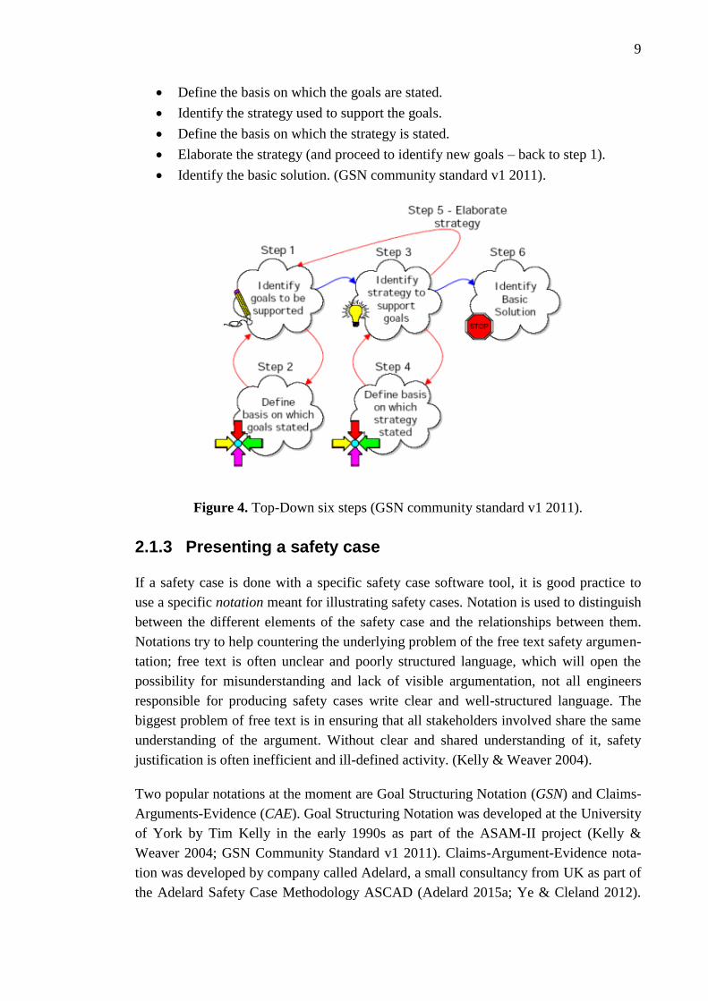
Yet another approach for developing the safety case goal structure is Top-Down method
defined by Kelly (1998) with six steps, also shown in Figure 4:
Identify the goals to be supported.
9
Define the basis on which the goals are stated.
Identify the strategy used to support the goals.
Define the basis on which the strategy is stated.
Elaborate the strategy (and proceed to identify new goals – back to step 1).
Identify the basic solution. (GSN community standard v1 2011).
Figure 4. Top-Down six steps (GSN community standard v1 2011).
2.1.3 Presenting a safety case
If a safety case is done with a specific safety case software tool, it is good practice to
use a specific notation meant for illustrating safety cases. Notation is used to distinguish
between the different elements of the safety case and the relationships between them.
Notations try to help countering the underlying problem of the free text safety argumen-
tation; free text is often unclear and poorly structured language, which will open the
possibility for misunderstanding and lack of visible argumentation, not all engineers
responsible for producing safety cases write clear and well-structured language. The
biggest problem of free text is in ensuring that all stakeholders involved share the same
understanding of the argument. Without clear and shared understanding of it, safety
justification is often inefficient and ill-defined activity. (Kelly & Weaver 2004).
Two popular notations at the moment are Goal Structuring Notation (GSN) and Claims-
Arguments-Evidence (CAE). Goal Structuring Notation was developed at the University
of York by Tim Kelly in the early 1990s as part of the ASAM-II project (Kelly &
Weaver 2004; GSN Community Standard v1 2011). Claims-Argument-Evidence nota-
tion was developed by company called Adelard, a small consultancy from UK as part of
the Adelard Safety Case Methodology ASCAD (Adelard 2015a; Ye & Cleland 2012).

10
These two notations used to build safety/assurance cases follow the same principal idea.
They use visual aid to help bring structure and deeper understanding safety arguments.
They do this by breaking down free text format to claims, arguments and evidence.
These are the very basic building blocks, or elements, of safety cases and the notations.
They can be defined as follows:
Claim (a.k.a. goal). Claims identify functional and/or non-functional require-
ments that must be satisfied by the system. Set of claims must by coherent and
as complete as possible, they define what the expected properties of the system
are. Claims can be decomposed to sub-claims at different levels of the system
architecture, design and operations. Claims and sub-claims are supported by ev-
idence components that identify facts or data, for which there is enough confi-
dence beyond any reasonable doubt. (Common Position 2014).
Argument (a.k.a. strategy). Above all, the safety case exists to communicate an
argument. It is used demonstrate how someone can reasonable conclude that a
system is acceptably safe from the evidence available. It is an attempt to per-
suade others, reasons are cited why a claim should be accepted as true. Argu-
ment should contain extensive references to evidence (SACM 2015). Often this
is based on the author’ personal experience. Safety arguments are typically
communicated in existing safety cases through free text. (Kelly & Weaver
2004).
Evidence (a.k.a solution). Evidence to support safety case is produced through-
out the system life cycle, and evolves in nature and substance within project.
Common position (2014) list three basic independent types of evidence which
can and must be produced: evidence related to the quality of the development
process; evidence related to the adequacy of the product; and evidence of the
competence and qualifications of the staff involved in all of the system life cy-
cle phases. It also agreed upon the fact that in the planning phase it shall be iden-
tified the types of evidence that will be used, and how and when this evidence
shall be produced. Evidence shall have enough confidence beyond any reasona-
ble doubt without further evaluation, quantification or demonstration. This kind
of confidence inevitably requires a consensus of all parties involved to consider
the evidence as being unquestionable. (Common Position 2014).
GSN is for explicitly representing the individual elements of a safety argument and the
relationships between these. Linked elements of the GSN network are described as a
“goal structure”. The purpose of any goal structure is the show, how a “top goal” is suc-
cessively broken down into sub-goals which are essential to achieve the top goal until a
point is reached where claims can be supported by direct reference to available solution.
(Ye & Cleland 2012; Change Vision 2015). Basic GSN elements (goal, strategy, solu-
tion, context, assumption, justification) are shown in Table 1. The table also gives a
short explanation of the elements and their typical use.

11
Table 1. Basic GSN elements (Ye & Cleland 2012.
With addition to basic elements presented above, GSN also has a number of extensions
available, which are explained in the GSN community standard (2011), with the most
important extension being the modular extension, which allows modularised intercon-
nected argumentation for larger more complex systems. Other popular extension is ar-
gument patterns, which allows structural and entity abstraction. (GSN community
standard v1 2011). Elements are connected to each other by line elements which mark
the type of their relationship. Two available line elements are ‘SupportedBy’ (line with
filled arrow head) and ‘InContextOf’ (line with empty arrow head). Figure 5 shows an
example diagram using GSN, including the basic elements.

12
Figure 5. An example of goal structure (GSN community standard v1 2011).
CAE (Claim-Arguments-Evidence) notation was developed as part of the Adelard Safe-
ty Case Methodology (ASCAD). According to Adelard, CAE is simple, yet effective
notation for presenting and communicating a safety argument (Ye & Cleland 2012).
This notation is also build from node elements with lines drawn in-between to mark
relations to each other. The core elements; claims, arguments, evidences, of CAE nota-
tion are defined in Table 2. Table also includes a short explanation for each of the ele-
ments and a description of their typical use.

13
Table 2. CAE elements (Ye & Cleland 2012).
In addition to claim, argument and evidence elements, CAE also has ‘Other’ and ‘Cap-
tion’ elements. ‘Other’ node is used for project context, for example assumptions and
system descriptions. ‘Caption’ nodes can be used to make comments. In CAE the ele-
ments are connected to each other with links, which shows the relation between them. A
basic example structure diagram made from basic CAE elements is shown in Figure 6.
Notation results in a diagram linking the components of the case together and showing
dependence between the elements.
Figure 6. A simple example of CAE diagrams (Adelard 2015a).

14
While using a certain notation may be the common way at the moment, safety assurance
domain standard ISO 15026 (see Section 2.1.4) does not specify the use of any notation,
graphical or otherwise. However, either of GSN or CAE doesn’t directly support ISO
15026:2013. Table 3 presents comparison between notation elements in the ISO/IEEE
15026, GSN and CAE. Note, that both notations have elements not mentioned in the
standard.
Table 3. Comparison between ISO, GSN and CAE elements (Dawson 2013).
2.1.4 Important literature
Few standards and literature were found important for understanding the underlying
concepts of thesis. They were ISO/IEC/IEEE standard 15026, Object Managements
Group’s metamodel for Structured Assurance Case (SACM), Common Position by in-
ternational nuclear regulators and authorised technical support organisations, and
Elforsk’s Safety Demonstration Plan guide. Here are a few notes about these docu-
ments:
ISO/IEC/IEEE 15026 consists of the following parts, under the general title Systems and
software engineering – Systems and software assurance which consists of the following
parts; Part 1: Concepts and vocabulary; Part 2: Assurance case; Part 3: System integrity
levels; Part 4: Assurance in the life cycle. ISO 15026 clarifies the concepts needed for
understanding software and systems assurance. The assurance case is relevant to some
extent in all parts. Part 2 concentrates on the contents and structure of the assurance
case. Part 3 relates integrity levels to their role in assurance cases, and Part 4 provides
details on integrating the assurance case into the system life cycle processes. (Valkonen
et al. 2016). A safety demonstration (as an artefact) is a specialisation of the assurance
case. In addition to evidence, arguments, and claims, standard includes the additional
concepts of assumptions and justification. (IEEE/ISO 15026-1 2013).
15
Structured Assurance Case Metamodel by Object Management Group defines a meta-
model for representing structured assurance cases and a set of metamodels to enable
information exchange related to systems assurance. The models provide a tool-oriented
approach and use ISO/IEC 15026 as a normative reference. The focus is on software-
intensive systems. Assurance Case Metamodel is constructed of Argument Metamodel
and Evidence metamodel (SACM 2015).
Common position (2014 revision) Licensing of safety critical software for nuclear reac-
tors: Common position of international nuclear regulators and authorised technical sup-
port organisations. The major result of the work is the identification of consensus and
common technical positions on a set of important licensing issues raised by the design
and operation of computer based systems used in nuclear power plants for the
implementation of safety functions. The purpose of the work is to introduce greater con-
sistency and more mutual acceptance into current practices. To achieve these common
positions, detailed consideration was paid to the licensing approaches followed in the
different countries represented by the experts of the task force. (Common Position
2014).
Elforsk Safety Demonstration Plan Guide: A general guide to Safety Demonstration
with focus on digital I&C in Nuclear Power Plant modernization and new build project,
Elforsk rapport 13:86, written by Marie-Louise Axenborg and Pontus Ryd from Solvina
Ab in 2013. Report’s mission was to produce a guide for how to demonstrate safety
with primary focus to digital I&C systems in nuclear power plants. It does not directly
mention safety cases, but introduces the concept of the Safety Demonstration which is
linked to the same thing, assure and demonstrate the safety along the whole life cycle of
a project. (Elforsk 2013).
2.2 Nuclear power plant
2.2.1 Nuclear power plants and instrumentation & control sys-
tems
A nuclear power plant (NPP) is a thermal power station, which source of thermal ener-
gy is the nuclear reactor. Nuclear reactor produces and controls the release of energy
from splitting the atoms of certain elements. In a nuclear power reactor, the energy re-
leased is used as heat to make steam to generate electricity. The principles for using
nuclear power to produce electricity are the same for the most types of reactors. The
energy released from continuous fission of the atoms of the fuel is harnessed as heat in
gas or water. The steam is then used to drive the turbines which produce electricity.
(World Nuclear Association 2015).

16
Nuclear fission is the main process of generating nuclear energy. Radioactive decay of
both fission products and transuranic elements formed in the reactor yield heat even
after fission reaction has stopped. In order to achieve fission, nuclear reactor needs neu-
trons in motion. When a neutron passes near to a heavy nucleus, for example uranium-
235, the neutron may be captured by the nucleus and this may be followed by nucleus
decaying into a different nucleus, releasing new neutrons and a very large amount of
energy. Nuclear fission is more likely to happen in fissile chemical elemental isotopes
such as uranium-235 and plutonium-239. As one nucleus typically releases 2 or 3 new
neutrons as part to decaying, the fission reaction needs to be controlled; otherwise it
would turn into uncontrolled chain reaction, resulting in enormous amounts of energy
and a meltdown. (World Nuclear Association 2014).
The main reactor design is the pressurized water reactor (PWR), which has water at
over 300°C under pressure in its primary circuit, and generates steam in a secondary
circuit. The less numerous boiling water reactors (BWR) make steam in the primary
circuit. Both types use water as both coolant and moderator, to slow neutrons. The main
components of nuclear reactor are:
Fuel. Uranium is the basic fuel; usually pellets are arranged in tubes to form
fuel rods.
Moderator. Material in the core which slows down the neutrons from fission for
causing more fission, it is usually water.
Control rods. Neutron-absorbing material which are inserted or withdrawn from
the core to control the rate of reaction or to halt it.
Coolant. A fluid circulating through the core so as to transfer the heat from it.
Usually moderator acts also as a coolant.
Pressure vessel. Contains the reactor core and moderator/coolant.
Steam generator. System where the high-pressure primary coolant bringing heat
from the reactor is used to make steam for the turbine.
Containment. The structure around the reactor and associated steam generators
which is designed to protect it from outside intrusion and to protect those out-
side from the effects of radiation in case of malfunctions inside. (World Nuclear
Association 2015).
The “central nervous system” of a nuclear power plant is the instrumentation and con-
trol (I&C) system architecture, together with plant operations personnel. Through its
various elements (e.g., equipment, modules, sensors, transmitters, redundancies, actua-
tors, etc.), the I&C system senses basic physical parameters, monitors performance,
integrates information and makes automatic adjustments to plant operations as neces-
sary. To accomplish its objectives of keeping track of hundreds of plant parameters, a
NPP contains thousands of electromechanical components, sensors and detectors. I&C
systems also display the key information about the plant parameters and deviations from

17
set points through the human-system interface to inform the operators about the status
of the plant. (IAEA 2011, IAEA 2016).
The I&C system architecture has three primary functions:
To provide the sensory (e.g., measurement and surveillance) capabilities to sup-
port functions such as monitoring or control and to enable plant personnel to as-
sess status.
To provide automatic control, both the main plant and of many ancillary sys-
tems.
To provide safety systems to protect the plant from consequences of any mal-
function or deficiency of plant systems or as a result of errors in manual actions.
(IAEA 2011).
Important feature of the I&C system is responding to failures and off-normal events,
thus ensuring efficient power production and safety. “Essentially, the purpose of the
instrumentation and control systems at a nuclear power plants is to enable and ensure
safe and reliable power generation.” So, the I&C systems serve to protect the various
barriers to any harmful release of radioactive emissions that pose harm to the public or
environment, and work as a critical element within the ‘defence in depth’ (see Section
2.2.2 and Tommila & Papakonstantinou 2016) approach for NPP. Therefore, much at-
tention should be given for the projects involving the design, testing, operation, mainte-
nance, licensing, operation and modernization of I&C systems. The challenges in sever-
al I&C areas are aging and obsolete components and equipment. With license renewals
and power uprates, the operation and maintenance of such systems may be cost-
inefficient and unreliable option. One solution to this is to modernize existing analogical
I&C systems to digital I&C, as well as implement new digital I&C systems in new
plants. (IAEA 2016, IAEA 2011).
2.2.2 Life cycle and the safety of nuclear power plant
As can be concluded from above, a nuclear power plant is a very complex sosio-
technical system with a lifetime from 30 to 60 years. One interpretation of the stages of
the life cycle of a nuclear power plant given by International Atomic Energy Agency is
shown in Figure 7. There are different models for the life cycle phases; usually they are
either bound to the passage of time or purpose-driven categories of activities. Basic life
cycle stages are siting, design, construction, commissioning, operation and decommis-
sioning. NPP will require a lot of design, maintenance and investments through its
whole life cycle to ensure the reliability and safety. Some components simply wear out,
corrode or degrade to a low level of efficiency and need to be replaced. Obsolescence is
also an issue; for instance older reactors have analogue instrument and control systems.
Periodic safety reviews are undertaken on older plants in line with international safety

18
conventions and principles to ensure that safety margins are maintained. (World Nuclear
Association 2015).
Figure 7. NPP life cycle (IAEA 2002a).
The safe operation of a nuclear power plant is based on safe power plant engineering,
highly capable and conscientious employees, and independent external supervision. The
cornerstone of nuclear safety is the Defence in Depth (DiD) concept, which means ac-
cording to IAEA (2007) “Hierarchical deployment of different levels of diverse equip-
ment and procedures to prevent the escalation of anticipated operational occurrences
and to maintain the effectiveness if physical barriers places between a radiation source
or radioactive materials and workers, members of the public or the environment, in
operational states and, for some barriers, in accident conditions”. The core of DiD is in
several independent and consecutive “defence lines” to prevent accidents. These include
both technical and organisational means to ensure plant safety. (Tommila & Papa-
konstantinou 2016).
However, in this work, we can focus on the I&C systems important to safety. The first
stage of the DiD approach of these systems is the planning and construction of equip-
ment and functions at a nuclear power plant in accordance with high quality require-
ments and adequate safety margins. Second, it is assumed that equipment may develop
faults or that operators will make mistakes, and the plant is equipped with protective
systems and equipment. In the event of operating fault, these will try to restore the plant
to a safe state. The third stage of defence in depth concept consists of the safety sys-
19
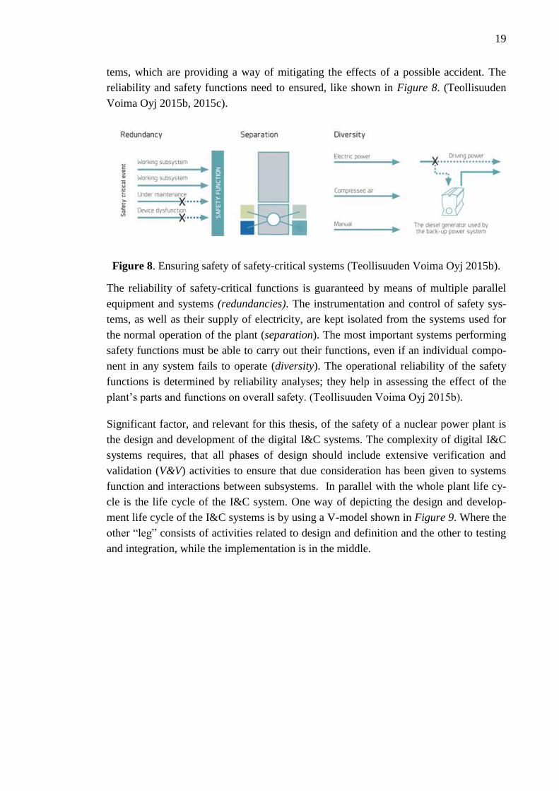
tems, which are providing a way of mitigating the effects of a possible accident. The
reliability and safety functions need to ensured, like shown in Figure 8. (Teollisuuden
Voima Oyj 2015b, 2015c).
Figure 8. Ensuring safety of safety-critical systems (Teollisuuden Voima Oyj 2015b).
The reliability of safety-critical functions is guaranteed by means of multiple parallel
equipment and systems (redundancies). The instrumentation and control of safety sys-
tems, as well as their supply of electricity, are kept isolated from the systems used for
the normal operation of the plant (separation). The most important systems performing
safety functions must be able to carry out their functions, even if an individual compo-
nent in any system fails to operate (diversity). The operational reliability of the safety
functions is determined by reliability analyses; they help in assessing the effect of the
plant’s parts and functions on overall safety. (Teollisuuden Voima Oyj 2015b).
Significant factor, and relevant for this thesis, of the safety of a nuclear power plant is
the design and development of the digital I&C systems. The complexity of digital I&C
systems requires, that all phases of design should include extensive verification and
validation (V&V) activities to ensure that due consideration has been given to systems
function and interactions between subsystems. In parallel with the whole plant life cy-
cle is the life cycle of the I&C system. One way of depicting the design and develop-
ment life cycle of the I&C systems is by using a V-model shown in Figure 9. Where the
other “leg” consists of activities related to design and definition and the other to testing
and integration, while the implementation is in the middle.
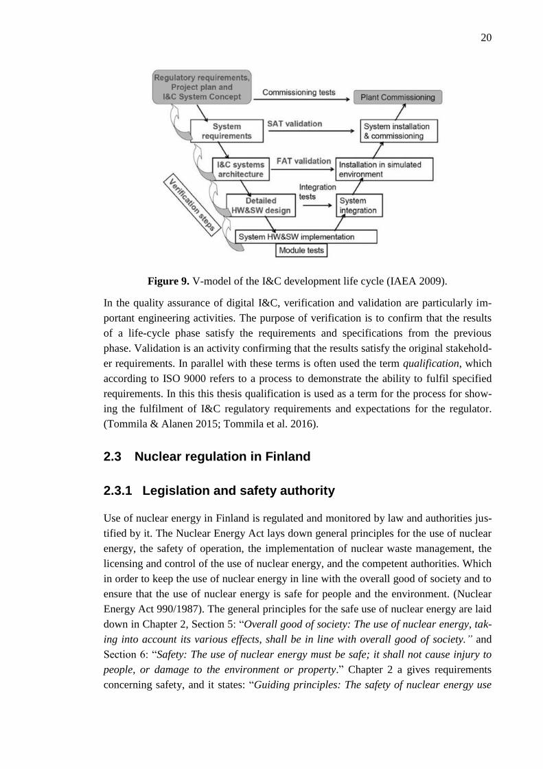
20
Figure 9. V-model of the I&C development life cycle (IAEA 2009).
In the quality assurance of digital I&C, verification and validation are particularly im-
portant engineering activities. The purpose of verification is to confirm that the results
of a life-cycle phase satisfy the requirements and specifications from the previous
phase. Validation is an activity confirming that the results satisfy the original stakehold-
er requirements. In parallel with these terms is often used the term qualification, which
according to ISO 9000 refers to a process to demonstrate the ability to fulfil specified
requirements. In this this thesis qualification is used as a term for the process for show-
ing the fulfilment of I&C regulatory requirements and expectations for the regulator.
(Tommila & Alanen 2015; Tommila et al. 2016).
2.3 Nuclear regulation in Finland
2.3.1 Legislation and safety authority
Use of nuclear energy in Finland is regulated and monitored by law and authorities jus-
tified by it. The Nuclear Energy Act lays down general principles for the use of nuclear
energy, the safety of operation, the implementation of nuclear waste management, the
licensing and control of the use of nuclear energy, and the competent authorities. Which
in order to keep the use of nuclear energy in line with the overall good of society and to
ensure that the use of nuclear energy is safe for people and the environment. (Nuclear
Energy Act 990/1987). The general principles for the safe use of nuclear energy are laid
down in Chapter 2, Section 5: “Overall good of society: The use of nuclear energy, tak-
ing into account its various effects, shall be in line with overall good of society.” and
Section 6: “Safety: The use of nuclear energy must be safe; it shall not cause injury to
people, or damage to the environment or property.” Chapter 2 a gives requirements
concerning safety, and it states: “Guiding principles: The safety of nuclear energy use

21
shall be maintained at as high a level as practically possible. For the further develop-
ment of safety, measures shall be implemented that can be considered justified consider-
ing operating experience and safety research and advances in science and technology.”
and about DiD: “Safety principle of defence-in-depth: The safety of a nuclear facility
shall be ensured by means of successive levels of protection independent of each other
(safety principle of defence-in-depth). This principle shall extend to the operational and
structural safety of the plant.” The Nuclear Energy Decree (161/1988) lays down more
specific provisions on how to fulfil the requirements set by the Nuclear Energy Act.
In Finland legislation is enforced and monitored at whole nuclear power plant level,
mainly through licencing process, which takes place in three steps, the decision-in-
principle, the construction licence and the operating licence. Participating organisations
and change of information is shown in Figure 10, it shows the connection between the
applicant (builder of the NPP) and the regulatory body, as well as the government.
Figure 10. Licencing of nuclear facilities in Finland (STUK 2010).
As shown in Figure 10, in Finland the authorized regulator is Radiation and Nuclear
Authority (STUK), which supervises nuclear power plants, nuclear materials and nucle-
ar waste. The supervision is based on the Nuclear Energy Act (990/1987). Which, in
order to keep the use of nuclear energy in line with the overall good of society and to
ensure that the use of nuclear energy is safe for people and the environment, lays down
general principles for the use of nuclear energy, the implementation of nuclear waste
management, the licensing and control of the use of nuclear energy, and the competent
authorities. STUK also participates in the processing of submitted applications for li-
censes in accordance with Nuclear Energy Act, supervises compliance with the terms of
the license and sets out detailed requirements concerning the licensed operations (Te-
ollisuuden Voima Oyj 2015a).
22
According to Section 7 r of the Nuclear Energy Act: “The Radiation and Nuclear Safety
Authority (STUK) shall specify detailed safety detailed safety requirements concerning
the implementation of safety level in accordance with this Act.” Based on the authoriza-
tion by the nuclear energy legislation, the Finnish Radiation and Nuclear Safety Author-
ity (STUK) publishes YVL guides that set out the detailed safety requirements for the
use of nuclear energy, and the supervisory practices adopted by STUK. (Nuclear Energy
Act 990/1987; TeollisuudenVoima Oy 2015a). The safety requirements of the Radiation
and Nuclear Safety Authority are binding on the licensee (applicant), while still giving
the licensee a right to propose an alternative procedure or solution to that provided for
in the regulations. If the licensee can convincingly demonstrate that the proposed proce-
dure or solution will implement safety standards in accordance with the Act, STUK may
approve it. (STUK 2015b). Most relevant YVL guides for this work are:
YVL A.1 Regulatory oversight of safety in the use of nuclear energy (22 Nov
2013),
YVL B.1 Safety design of a nuclear power plant (15 Nov 2013),
YVL B.2 Classification of systems, structures and components of a nuclear fa-
cility (15 Nov 2015), and
YVL E.7 Electrical and I&C equipment of a nuclear facility (15 Nov 2015).
(STUK 2015a).
2.3.2 Licensing and the required documents
The use of nuclear energy in Finland without the license provided by Nuclear Energy
Act is prohibited. All operators of nuclear energy must have a license granted by the
regulatory body in order to build or operate a nuclear power plant. Licensing is effective
way of monitoring activities and adherence to rules and regulations. To get a license, the
applicant must demonstrate the fulfilment of several safety and other requirements,
which are set by legislation and regulations. A licence is a legal document issued by the
regulatory body, granting authorization to create a nuclear installation and to perform
specified activities. The Finnish nuclear regulatory body, STUK, is an authority desig-
nated by the government as having legal authority to conduct the regulatory process,
including issuing authorizations. (IAEA 2007; IAEA 2010). Usually license is applied
for constructing and operating a nuclear facility, but it also applies to modification of an
existing plant. (Teollisuuden Voima Oyj 2015a). Licensing is done by submitting the
documents, which demonstrate the fulfilment of the regulatory requirements set the reg-
ulator. Licensing is not done as a single instance, but during the design and construction
phases of the NPP’s lifecycle. The most important milestones of the licensing process
are the decision-in-principle, construction license and operating license (also shown in
Figure 11). Essential part of these applications is the demonstration of the safety of the
NPP and its systems.
23
The documents to be submitted to STUK in each phase are specified in Finnish nuclear
legislation and the YVL Guides. STUK demands to see a specified information, plans
and analyses, but doesn’t specify how they are presented. If the documents are electron-
ically submitted, STUK needs to be consulted about the relating procedure. The licensee
will need to assess the acceptability of the safety documents prior to their submission to
STUK. Licensee needs to ensure that the safety requirements concerned are met. The
acceptability assessment shall be made by independent conductor of the authors of the
documents. (YVL guide A.1 2013).
Example of specified document structure is given in YVL Guide A.1 (2013) Annex B.2:
“Document content and the mode of presentation claims, that the application document
shall state the factual justification of the operations presented in the application com-
plete with reasoning. Compliance with official regulations and guides does not entitle
anyone to ignore information that could yield better results with regards to safety. The
documents shall be clearly structured. This means for example that purpose, implemen-
tation, assessment, related analyses and the conclusions are clearly separated from
each other. The facts presented, conclusions drawn and statements made in a document
shall represent the licensee’s best knowledge in the matter. Any contradicting result
must also be acknowledged.” Another on is given in YVL Guide B.1 (2013): “The doc-
umentation describing the nuclear plant, its systems and their design shall be clearly
structured, comprehensive, high quality, unambiguous, traceable and capable of ac-
commodating any updates. It shall be made using clear and precise presentation meth-
od that is understandable to experts to the various fields of technology and to permit
version management of programmable systems.”
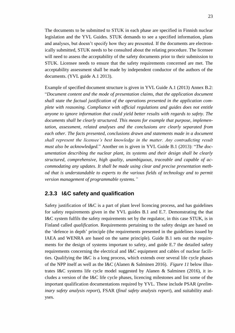
2.3.3 I&C safety and qualification
Safety justification of I&C is a part of plant level licencing process, and has guidelines
for safety requirements given in the YVL guides B.1 and E.7. Demonstrating the that
I&C system fulfils the safety requirements set by the regulator, in this case STUK, is in
Finland called qualification. Requirements pertaining to the safety design are based on
the ‘defence in depth’ principle (the requirements presented in the guidelines issued by
IAEA and WENRA are based on the same principle). Guide B.1 sets out the require-
ments for the design of systems important to safety, and guide E.7 the detailed safety
requirements concerning the electrical and I&C equipment and cables of nuclear facili-
ties. Qualifying the I&C is a long process, which extends over several life cycle phases
of the NPP itself as well as the I&C (Alanen & Salminen 2016). Figure 11 below illus-
trates I&C systems life cycle model suggested by Alanen & Salminen (2016), it in-
cludes a version of the I&C life cycle phases, licencing milestones and list some of the
important qualification documentations required by YVL. These include PSAR (prelim-
inary safety analysis report), FSAR (final safety analysis report), and suitability anal-
yses.

24
Figure 11. I&C system life cycle model (Alanen & Salminen 2016).
From the safety case point of view, it is interesting, that the licensee, according to YVL
guide B.1 (2013), has the obligation to (among other things):
Ensure that the design and implementation of the nuclear facility and its systems
are safe and fulfil the safety requirements.
Demonstrate that the nuclear facility and its systems are safe and that the safety
requirements are met, and
Maintain detailed design documentation to be able to ensure the design integrity
and safety of the facility over its entire service life.
This is interesting, because, as was explained in Section 2.1, safety cases are meant to
assure the stakeholders that the requirements presented above are fulfilled.

25
3. EXECUTION OF RESEARCH
The research goal was to evaluate software tool options that would be suitable for de-
veloping a safety case for nuclear I&C. The goal was divided into four sub goals, which
are presented in Figure 12. The figure also describes the work flow of thesis, starting
from the research problem then moving the research methods and finally to the result. It
also presents the important outcomes of each sub goals.
Describe safety case and terminology.
Description of nuclear safety
case
Development process
Tool requirements
Evaluation
Sub-goals Outcome
Evaluate software tool options for the development of a safety case for justifying safety of nuclear I&C
Result
Research problem
Research methods
Tool searchand review
Outline a development process for a safety case.
Define requirements for the tool features.
Evaluate the tools against the requirements.
Recommendations for tool option
Figure 12. Execution of research.

26
First goal was to settle the requirements against which the tools would be evaluated, as
well as describing a way of using the safety case approach in Finnish nuclear I&C justi-
fication. It was decided to approach this through the development process of a safety
case. If a development process in a suitable general level could be outlined, the re-
quirements could be then derived from the activities relating to that process. In other
words, the tools could be then studied for features supporting the outlined activities of
developing the case. Ideas for the safety case description and the development process
were taken from the qualification process of Finnish nuclear I&C (Valkonen et al. 2016,
Alanen & Salminen 2016, Johansson 2015), as well as borrowing features from safety
demonstration approach (Common Position 2014) alongside structured safety
case/assurance case standards presented in Section 2.1.4 (ISO 15026 and OMG’s
SACM). In addition, it uses the term nuclear safety case as a key concept (Valkonen et
al. 2016). Terminology around safety cases can be a source of confusion as explained in
Section 2.1.1, so one more task of the description was to define the terms used in this
thesis. For the validity of the description, VTT and STUK experts and materials were
used as sources of information and knowledge.
From the outlined development process, it was finally possible to derive the tool re-
quirements. In Section 4.3 those features are explained and categorized. The presented
description and process works as justification for the selected features. Next, tools for
the review needed to be selected. So, first a preliminary tool search was performed, it
was done by searching for such tools from the internet, as well as from literature related
to development of safety cases. It was decided to review currently available tools, as
during the preparation it became clear that there are tools available in the market for
creating safety/assurance cases. An alternative choice could have been developing a
software tool, but this was rejected as a too time consuming task for this thesis. An ini-
tial list (found in Section 4.4) of the tools found was taken into further study. After a
preliminary study of usability and availability, as well as hands-on experiments with the
tools, the initial list was narrowed down to the final selection of tools for the review
(also found in Section 4.4).
The tools selected for evaluation were reviewed for their features. The tool review was
performed by testing the tools, studying tools’ manuals and other available relevant lit-
erature. Observations about otherwise interesting tool functions, not included in the re-
quirements, found during the review were also collected and are mentioned in the Sec-
tion 4.5. Tool review only focused on explaining how the tools worked and reporting
the findings during the tests. More precise analysis on how the tools fulfil the require-
ments and how they compare against each other was done in Section 5.1. Based on the
results from Chapter 4 and the analysis of tools in Section 5.1, conclusion about the
study are given in Section 5.2.

27
4. RESULTS
4.1 Nuclear safety case
As a background for the evaluation criteria, and applying the safety case concept to
Finnish nuclear practices, the intended usage environment in the nuclear I&C domain
for the tool is outlined in this Section 4.1. The main terms of this description are nuclear
safety case, safety demonstration and structured safety case. Figure 13 illustrates the
big picture of the terms and the relationships between them. Compared to background
material in Section 2.1, this usage environment description takes the ideas of safe-
ty/assurance case presented and formats them more suitable for justification of nuclear
I&C between the applicant and the regulator in Finnish practices. In this description
structured safe case is closest to the concept of safety case presented in Section 2.1.
However, the safety case presented there is a very wide and confusing mix of different
definitions from various sources. In this description the ideas are separated into three
different defined terms, which are tailored to fit the required context.
Nuclear safety case is defined as an informal overall term referring to totality of the
material needed for supporting the licensee in the safety management of a target system.
In this context the target system is the nuclear power plant. It includes all the relevant
safety material, and other related context documentation (system descriptions, specifica-
tions, practices, examples shown in Figure 13) required by different stakeholders. Safe-
ty case should be clear and comprehensive way of managing accurate and objective
information on risk and control measures for those making decisions that may affect the
safety of the nuclear facility. It is an artefact changing over time, as the plant goes
through modifications, or the understanding of the safety related issues change. As was
mentioned in Section 2.1, the safety case is mainly used for three major purposes; to
convince ‘one-self’ that the system is safe, demonstrate safety to reviewers and regula-
tor, and minimizing project and licencing risks (Elforsk 2013). In this description, the
purpose of a nuclear safety case is providing the licensee with the information required
for the safety justification of nuclear I&C systems. Part of nuclear safety case is the ma-
terial used for qualifying I&C system for the regulator.
Safety demonstration is a part of the nuclear safety case. It is the artefact, which in-
cludes the reasoning and the arguments required for the safety justification (Common
position 2014). As was explained in Section 2.1, argumentation is used to connect the
evidence to the safety claims through proper argumentation. Safety demonstration is a
term given for the set of arguments and evidences, which support a selected set of
claims needed for convincing the safety of the system in a given environment for a cho-

28
sen stakeholder. In this description the main use is the qualification of I&C system to
the regulating authority. Safety demonstration should be understood as a set of infor-
mation stored in databases or human readable documents. It uses the material available
in the nuclear safety case, for establishing suitable and adequate safety claims and refer-
ences to evidence artefacts. As well as nuclear safety case, the safety demonstration is
susceptible to changes as systems and artefacts are modified.
is made foris made for
Nuclear safety case
Safety reportis
summarised in
System solutions
has part
Safety demonstration
Development practices
Hazards and failure modes
Analysis results
O&M practices
describes
describes
describes
describes
can have presentation
Structured safety case
is result of
Safety management
Licencing, permitting
Qualificationdescribes
Open issues, uncertainties
Assurance case
Claim
Argument
Evidence
includes
includes
includes
is subtype of
Figure 13. Nuclear safety case terminology and relations (Valkonen et al. 2016).
Structured safety case is a one way of presenting the safety demonstration in a struc-
tured, transparent and traceable manner. It is a visual or textual presentation, usually
utilizing a recognized notation like CAE or GSN (see Section 2.1.2). It should be fol-
lowing some related standard or metamodel, like OMG’s SACM or ISO 15026 (see
Section 2.1.4). Notations following the guidelines set by standards give the safety
demonstration the traceability and transparency needed with clear claim – argument –
evidence structure. Claims, arguments and evidences should all be their own elements in
the diagram, document or other type of structure, and easily distinguished and under-
standable from other elements. Each relevant element should have traceability links to
system artefact documents, which are stored in a distinguishable data repository or da-
tabase. It should be in a form of one or more human-readable documents accessible to
all relevant stakeholders. If the target system is very large or complex, in many cases it
is convenient to divide the structured safety case into sub-cases. Each of the sub-cases
can focus on specific area or component of the system. Relevant example would be an

29
I&C sub-case of a whole nuclear power plant. These sub-cases can then be gathered
together in a plant level safety case as complete safety demonstration. Structured safety
case is the artefact which is done with the help of software tool.
4.2 Development process
As said, the development of a structured safety case defined above will be produced
with the help of a software tool. An overview of the safety case development process
was needed for defining the required tool features. Based on the description of the pre-
vious section, a generalized development process for structured safety case is presented.
The development process was defined by first defining the possible users, then the use
scenarios and finally the actions performed with the tool. Key terms for this section are:
stakeholder, use scenario, activity, and user role, their relations are represented in Fig-
ure 14. The terms and their relations will be explained in detail in this section.
Structured safety case
Structured safety case tool
Stakeholder
Feature
has Requirement
has
User role
satisfies
Is developed with
takes
supports
Development process
supports
Activity
consist of
Use scenario
has
Figure 14. Key terms of development process.
Important factors for the development process were the stakeholders and their possible
needs for the structured safety case tool. In the previously described nuclear safety case
there are three relevant stakeholders identified; system owner, regulator and designer.
In Figure 14 stakeholders can be seen as sources for the use scenarios. In this work the
stakeholders are defined as follows:
System owner is the body trying to justify the safety of a system to itself and
other stakeholders. In this context, the system owner is the applicant, trying to
justify the safety of its I&C system for the regulating authority, usually for qual-
ification purposes. System owner builds the nuclear safety case and does the re-
quired safety demonstration using the structured safety case. In some cases, the
safety case builder’s role can be taken by a third party, probably a technical sup-
port organisation (TSO, like VTT), using the tool for a safety demonstration of a
smaller system or assessing someone else’s safety demonstration. System owner
is the main actor and user of the safety case tool and will possibly have several
different persons or teams working on the structured safety case.

30
If system owner is the one doing the justification for a system, then regulator is
one of the targets for it. Regulator is the stakeholder working as regulatory au-
thority and the main body supervising and guiding the applicant in the qualifica-
tion process of the nuclear I&C. Regulator is one of the reviewers of structured
safety case done by the system owner. This stakeholder doesn’t have all that
many uses for the tool, but they will have a few requirements for it. Regulator
could use the tool, for example, for viewing and commenting the safety case, or
they could work with documents generated with the tool. The structured safety
case for qualification of I&C is done against the requirements of the regulator,
and the tool needs to able to fulfil them.
Designer is the stakeholder, who supplies the system owner with systems, com-
ponents, specifications and their evaluation material. In this context, the designer
is seen as an independent team within the systems owner of a third party produc-
ing part of I&C system or a single component for more complex system. De-
signer is producing evidence material for the system owner’s safety case and
their V&V requests. They can also be system owner for their own component
level, or specification safety case, which can then be used as a sub-case for over-
all system owner’s plant level safety case.
For the scope of this thesis the structured safety case will be considered to be developed
by the stakeholders defined above. Stakeholders’ needs change as the project and the
systems develop, but some similarity can be seen between different use cases of the
tool. From these needs three example types of usage scenarios for the structured safety
case tool could be identified:
An organisation responsible for building and qualifying I&C system plans and
develops a safety demonstration and a structured safety case, from the material
in nuclear safety case, in parallel with the system life cycle. The structured safe-
ty case is planned, prepared and reviewed by the organisation itself, so it is
ready for the use. Other activities related to this scenario is managing the safety
case as a project, as well as maintaining the case when the target system chang-
es. This is a system level safety case, which can be divided into sub-level cases.
A supplier of a subsystem, or a manufacturer of a component, develops a safety
demonstration for its own deliverable. It could be used as part of the system
level safety demonstration done by the customer, e. g. as evidence of their case
or as a ready sub-case.
In the last example, an independent assessor analyses the safety of the specified
solution or process against selected claims, argument and evidences presented
in a delivered structured safety case or material exported from it. This can relate
to development process of the structured safety case or the qualification process
following it. It differs from the previous usage scenarios; in this case it is not
the goal to justify a safety of a system, but assessing the resulting demonstra-

31
tion. Results can, if needed, be integrated to the overall safety case. Another in-
teresting approach would be that the assessing of the safety justification could
be also done in a form of a structured safety case.
As part of development process for the structured safety case, some persons and teams
that would be working on it were identified. They will also be the users of the software
tool. As explained above, different stakeholders can have same usage scenarios as part
of their developing or qualification processes. To cover the same scenarios done by dif-
ferent stakeholders with the tool, user roles are introduced. In this way it is possible to
move from stakeholders to more generalized terms. Any stakeholder can have the user
role they need for that certain activity. User roles are safety case owner, developer, re-
viewer, and administrator. These four roles are assumed to cover the basic functions of
the development process.
Safety case owner is a person or a team responsible for the safety case as a pro-
ject. They are responsible for using the structured safety case or relevant parts of
it as qualification documentation in cooperation with the regulator. This user
role is usually taken by the system owner, but any stakeholder making their own
structured safety case will need it. Safety case owner role does the planning ac-
tivities and defining the structure for the structured safety case, these mean plan-
ning the resources and artefact needed for the case.
Developer is a person/team providing the structured safety case with planned
content. Providing the content happens using the structure developed by the
safety case owner and filling in the arguments with corresponding evidence
gathered from validation and verification (V&V) processes or acquired else-
where. Developer is responsible also for evaluating the provided evidence for
confidence as well estimating how well it matches the requirements.
Reviewer is either the person or team reading, using, commenting or assessing
the correctness and the validity of the case. It can be a role within the organiza-
tion making the safety case or its target stakeholders viewing and commenting
the case, or otherwise use the content of the case for different purposes. Review-
er gives feedback to safety case owner about the case, as well as change and
clarification requests. Each stakeholder should have its own reviewer, it can be
in-house or third party TSO.
Administrator is a bit different role, and it is solely for the tool side of this de-
velopment process. This user role is responsible for managing the structured
safety case from the software and IT management side; they make sure every
other user has the change to use the tool as intended and the configuration man-
agement and security is in order.
Figure 15 summarizes the relationship between stakeholders, user roles, use scenarios,
the tool and requirements.

32
Stakeholder
has
System owner
Regulator
Designer
Requirement
User role
Reviewer
SC owner
Administrator
Developer
has part
has part
has part
comes from
is example of
is example of
is example of
is example of
Structured safety case tool
supports
Usage scenarioshas
Figure 15. Main terms of the development process and their relations.
Now, when the stakeholders, use scenarios and user roles are defined, the final task is
defining the development process of the structured safety case. All the stakeholders
have similar use scenarios and user roles, which will need certain features from the tool.
These interests were sorted under relevant categories, which could be then generalized
at fitting level for the scope of this work. These categories are called activities, slightly
like defined in ISO 15288 (2015). The focus for the development activities was strictly
from the tool point of view, so certain assumptions were made for boundaries of the tool
usage environment. The selected boundaries help determining certain artefacts and ac-
tivities which are done outside the tool and can be left outside of the required tool fea-
tures; the most notable being the safety case plan and all the evidence artefacts. At the
same time boundaries help narrowing down the scope of this work. Activities and arte-
facts not studied are generally thought to be irrelevant or difficult to implement for the
selected tool environment.
The activities for developing a structured safety case expected are defining, inserting
evidence, reviewing and managing. These activities are carried out in an iterative fash-
ion in parallel with the phases of the system development. Figure 16 tries to clarify the
process of preparing a safety case with the help of activities introduced above; further
explanation of it is given below.
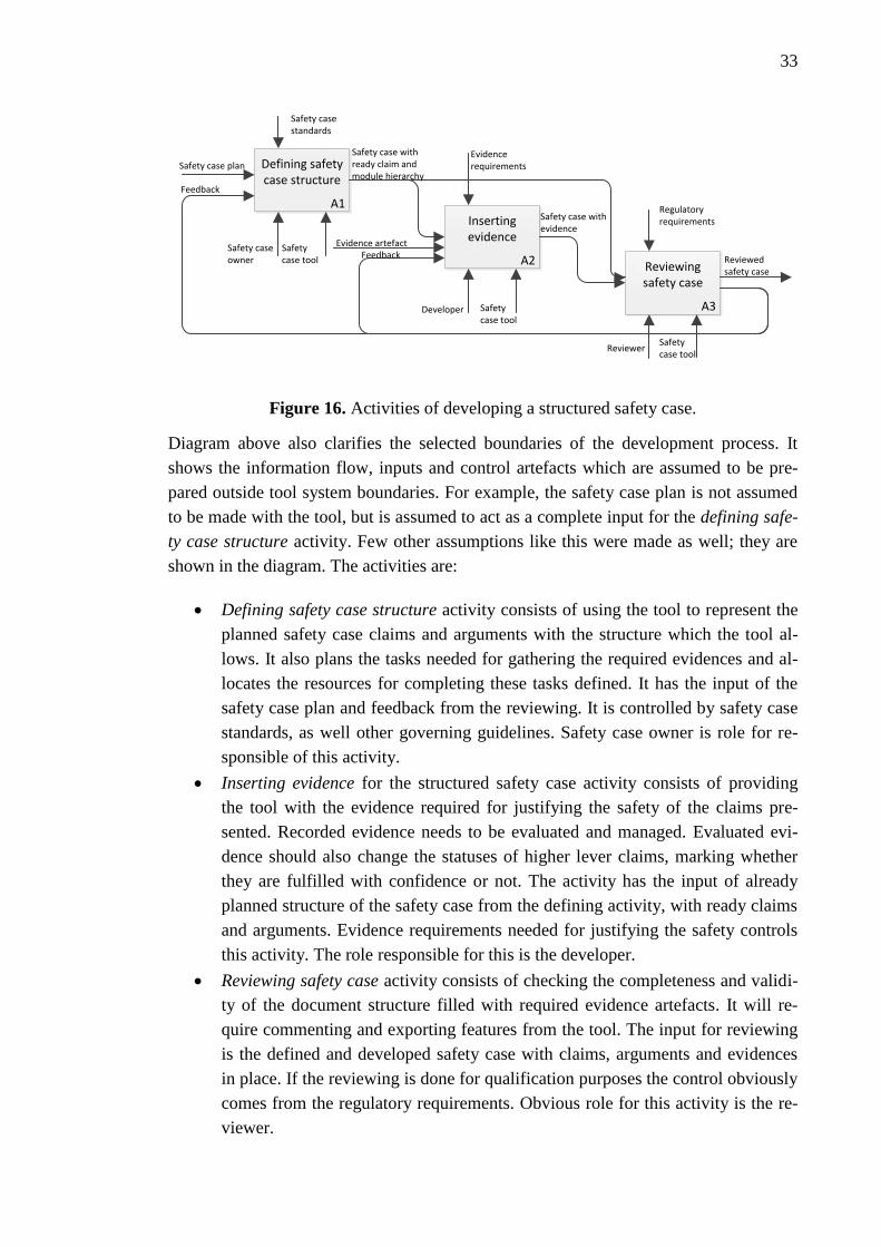
33
A1
Defining safety case structure
A2
Inserting evidence
A3
Reviewing safety case
Safety case plan
Evidence artefactSafety case owner
Developer
Reviewer
Reviewed safety case
Feedback
Safety case with ready claim and module hierarchy
Safety case with evidence
FeedbackSafety case tool
Safety case tool
Safety case tool
Safety case standards
Evidence requirements
Regulatory requirements
Figure 16. Activities of developing a structured safety case.
Diagram above also clarifies the selected boundaries of the development process. It
shows the information flow, inputs and control artefacts which are assumed to be pre-
pared outside tool system boundaries. For example, the safety case plan is not assumed
to be made with the tool, but is assumed to act as a complete input for the defining safe-
ty case structure activity. Few other assumptions like this were made as well; they are
shown in the diagram. The activities are:
Defining safety case structure activity consists of using the tool to represent the
planned safety case claims and arguments with the structure which the tool al-
lows. It also plans the tasks needed for gathering the required evidences and al-
locates the resources for completing these tasks defined. It has the input of the
safety case plan and feedback from the reviewing. It is controlled by safety case
standards, as well other governing guidelines. Safety case owner is role for re-
sponsible of this activity.
Inserting evidence for the structured safety case activity consists of providing
the tool with the evidence required for justifying the safety of the claims pre-
sented. Recorded evidence needs to be evaluated and managed. Evaluated evi-
dence should also change the statuses of higher lever claims, marking whether
they are fulfilled with confidence or not. The activity has the input of already
planned structure of the safety case from the defining activity, with ready claims
and arguments. Evidence requirements needed for justifying the safety controls
this activity. The role responsible for this is the developer.
Reviewing safety case activity consists of checking the completeness and validi-
ty of the document structure filled with required evidence artefacts. It will re-
quire commenting and exporting features from the tool. The input for reviewing
is the defined and developed safety case with claims, arguments and evidences
in place. If the reviewing is done for qualification purposes the control obviously
comes from the regulatory requirements. Obvious role for this activity is the re-
viewer.

34
Managing safety case tool consist of configuration management and managing
the security of the safety case tool environment. However, it is not part of Fig-
ure 16. Managing a safety case is seen as a separate activity from preparing the
safety case as it mainly consists of regular data administration activities and con-
figuration management. It focuses on the version history, user management and
the change control.
Defining, evidence providing and reviewing can be seen as part of preparing a safety
case in somewhat straightforward fashion, where next step will generally succeed to
previous one. However, an important part of the safety case is ensuring its validity and
adequacy. So, there needs to be strong iterative interaction between the defining and
developing activities and the reviewing process as seen in Figure 16. So, the activities
should be considered not to be tied to a time-line.
With the help of these notions and descriptions behind them, it is possible to define the
features required from the software tools, which would be used to develop the struc-
tured safety case used by the stakeholders taking a certain user role and using it in one
of the defined user scenarios while performing a certain activity.
4.3 Tool requirements
As was explained in the previous section, tools are expected to support certain activities
of the development process of the structured safety case. They do this by having certain
features, which will help user roles accomplish their tasks. Features were kept on a very
general level in this thesis for reducing the complexity of the tool review. Tool features
are divided into five categories, which are planning, structure, data, review, and man-
agement (Figure 17). This was done for the ease of organising the features and compar-
ing the tools between the categories rather than single features. In the tool review in
Section 4.5, the selected five tools are reviewed for their possible features and the re-
marks are gathered loosely under the feature categories presented. Further and more
exact analysis of the tool features is provided in the Section 5.1.
Tool features
Structure
Data
Review
ManagementPlanning
Figure 17. Tool feature categories.
Planning category includes features, which help the safety manager while plan-
ning for the actions of developing the structured safety case. Relevant features

35
for planning are defining the required tasks for gathering the required data, as
well as naming the persons responsible for completing each structure element
with the required data. Other planning features would be defining a development
schedule and laying down deadlines and reminders for the responsible develop-
ers.
Second feature category is structure. These features include tasks like defining
the claim-argument-evidence structure, in this concept this means transforming
the safety case plan in to structured safety case form as a visual and traceable
presentation of the safety demonstration. Important part of traceability is show-
ing the connections between the nodes and the ID and titles of them each. Struc-
ture features should also support the possibility of re-using parts of other struc-
tured safety cases, ready claim libraries or patterns. Important part of defining
the structure of the case is dividing the large scale system in to smaller, easier to
manage, sub system level cases. Hopefully the tools would also guide the user
for making a valid and plausible safety case structure, with proper claims and
arguments.
Data category includes features which provide the structured safety case with
required evidence and context data and artefacts. There are different ways of
providing data, it can be writing straight to the diagrams, or preferably copying
it from other software or hyperlinking to relevant directory or other data reposi-
tory. Also the safety justification data, usually evidence artefacts, should be pos-
sible to be evaluated for confidence. Evaluation of the elements should also be
visible in the tool for easier assessing of the completion.
Review category is meant for features helping with evaluating and commenting
the completeness of the planned, structured and filled safety case diagram, as
well as utilizing the ready artefact for its possible uses. Main features would be
changing comments and other information between the assessor/user and the de-
veloper/owner of the safety case. Other relevant features would be automatic
functions for evaluating the correctness of the structure and the integrity of the
evidences. Exporting relevant material from the diagram or model for reviewing,
assessing, sharing and reading purposes falls under this category too. As well as
creating specified reports from the information provided. For reviewing it would
be important to also remind to user about out-dated or undeveloped elements in
the structure.
Management was considered as a separate category from the previous four. It
doesn’t include features which focus on developing the safety case, but instead
help with configuration management and other general software management
features. Helpful features for configuration management are user management,
version history and change control.

36
The most essential tool feature requirements can be selected from the descriptions of the
feature categories and the development process presented previously. They are gathered
in Table 4 under the relevant category.
Table 4. Compilation of tool requirements.
4.4 Tool selection
For the tool review, existing tools for creating a structured safety case were searched.
Some help for it was found from guides and papers relating to assurance/safety cases.
During the search, all tools found were considered as the tool option choice and were
preliminary studied. It didn’t matter, whether the tool was a commercial product, free
software or a plugin for some pre-existing software. Ideally, it would be good to com-
pare the tools not only against the selected criteria, but against each other as well. It was
noticed, that the tools weren’t specifically made for certain types of systems, like nucle-
ar I&C. So an assumption was made, that any of the tools could also be suitable for nu-
clear I&C. The initial list for structured safety case tools found in the tool search phase
included:
ACEdit (https://code.google.com/archive/p/acedit/)
AdvoCATE (https://ti.arc.nasa.gov/m/profile/edenney/papers/sassur2012.pdf)
ASCE (http://www.adelard.com/asce/)
Astah GSN (http://astah.net/editions/gsn)
CertWARE (http://nasa.github.io/CertWare/)
Requirement
Resourcing
Scheduling
Requirement
Argument structure
IDs and titles
Modules
Templates
Writing
Linking
Importing
Evaluating
Assessing
Model checking
Commenting
Exporting
User management
Change management
Security
Pla
nSt
ruct
ure
Dat
aR
evi
ew
Man
age

37
D-case Editor (http://www.jst.go.jp/crest/crest-os/tech/D-CaseEditor/index-
e.html)
E-Safety Case (http://www.rmri.co.uk/what-we-do/software/e-safety-case/)
GSN CaseMaker (http://www.edifgroup.com/)
GSN Editor (source not available anymore)
GSN Visio Add-on (source not available anymore)
ISCaDE (http://www.iscade.co.uk/Index.htm)
NOR-STA (https://www.argevide.com/en/products/assurance_case)
These tools were taken into further research, where their availability and operation was
studied. For the scope of this thesis, the list needed to be shortened. With a short exami-
nation, few of the most interesting tools were selected for the review part. Also, some of
the tools didn’t exist anymore, weren’t made available for testing or didn’t work at all,
so this affected their selection process. Tools were tried to be downloaded, installed and
tested by the author. Certain tools required a licence and the licence was asked from the
company managing the tool. All the companies, which were asked, were kind enough to
offer an academic licence for testing the tools. The final tools selected for the tool re-
view were: Astah GSN, ASCE, NOR-STA, D-case Editor and ACEdit. These tools are
reviewed in the Section 4.5.
Out of these five tools Astah GSN, ASCE and NOR-STA are commercial software,
which all required a licence. D-case Editor and ACEdit are plugins working for inte-
grated development environment software Eclipse, which is a free workspace and ex-
tensible plug-in system for primary developing Java applications (Eclipse Foundation
2016). For this work Eclipse version 4.5 (Mars) with the Eclipse Modelling Tools pack-
age was used. The features of Eclipse were not studied much further. Further introduc-
tion for each of the tools is given under the relevant sub-section in the Section 4.5.
Rejected tools
These are the tools from the initial tool list which were considered, but rejected from
this thesis for certain reasons. Mostly because they weren’t available for testing; either
they weren’t available at all anymore or because no proper information for downloading
or operating them was found. Most of these tools were referenced in some related
sources and then checked upon.
These tools included:
CertWARE. CertWARE is a modelling tool plugin for Eclipse. It is meant for
developing, maintaining, and analysing assurance cases. It was developed and
maintained by NASA, but it seems this tool is no longer supported or available
for testing. It will be replaced by AdvoCATE at some point.

38
AdvoCATE. AdvoCATE is another NASA’s Eclipse plugin, the name comes
from Assurance Case Automation Toolset. The tool is meant for automated con-
struction and assessment of safety cases, with a goal of developing a framework
for the automated creation and assembly of assurance cases using a model-based
transformation. Tools is not ready yet, and there is not enough information
available about it for considering it a valid option, except a whitepaper from
2012 (Denney et al. 2012). However, it was hinted at SAFECOMP 2015 con-
ference that this tool is not ready yet, but it’s still in the making. It could be a
good choice for further study when it gets released.
GSN Editor by Dependable Computing, E-Safety Case by Praxis HIS, IS-
CaDE by rcm2 and GSN CaseMaker by ERA Technology. These tools were
presumably available at some point, but none of them were able to get installed,
nor enough other reference material found for the tool review.
4.5 Tool review
4.5.1 Astah GSN
Astah GSN is a tool for creating GSN diagrams ‘goal structures’ and regular mind
maps. Astah GSN is created by Change Vision, Inc. from Japan, founded in 2006. It is a
commercial tool, which is available for download with yearly licences available for pur-
chase. The licence includes support and upgrades. There are licences available for a
single user or in a larger company bundle. Astah GSN is a part of modelling tools in-
cluding Astah Professional (UML & ERD platform for software development) and
Astah SysML (for modelling and analysing complex systems). In Astah GSN webpage,
the tool is described as “An intuitive safety modelling platform for designing System
Assurance, Dependability, Safety and more”. (Change Vision 2016). Astah GSN ver-
sion 1.1.0/42c363 was used for this review. It was released 24th
of June 2015. At the
moment, Astah GSN is updated and developed rather regularly; new content seems to
come up every now and then. The company (Change Vision) was kind enough to grant
a free academic licence for the review of their tool. The tool has good operating system
(OS) support (Windows, Linux and Mac), and it has good user support.
This thesis focuses on GSN side of the software. The basic user interface (UI) of Astah
GSN is shown in Figure 18. The UI is divided into management view, project view,
property view, and diagram editor. Management view is for controlling the tool, project
view for controlling the current project or switching between different projects, property
view is used to add the data behind the elements seen in the project or diagram editors,
diagram editor is used for browsing and building the goal structure.

39
Figure 18. Astah GSN user interface and different views (Change Vision 2015).
Astah GSN doesn’t have any proper features for the planning category. Only function,
which can substitute for resourcing or scheduling features, is the TaggedValue tab in the
property view, where users can write down their own free text properties for each of the
nodes. This gives a way for planning for schedule or naming the liable person, but it is
just basically a blank row for a simple text.
For structure feature category, Astah fully supports the basic GSN notation and at least
the modular and entity abstraction extensions (this gives the possibility of marking ele-
ments as uninstantiated or underdeveloped) from the GSN community standard (2011).
Modular support is important for handling more complex system by allowing splitting
them into smaller diagrams instead of one large goal structure. Astah supports reusing
of old goal structures as templates for new diagrams, as well as user made templates.
There are two ways for building the structured safety case. The easier way is to model
the safety case structure with the diagram editor, where one can drag and drop the indi-
vidual elements of the argument from the toolbar straight into the diagram and use GSN
linking elements to link them together. The other way is adding elements to the project
view and modifying them from there.
For data category, Astah GSN supports very basic features for inserting the wanted ar-
gument text or evidences. Each element will have its unique id and title, which can be
changed by the user. The user can re-name all the elements, and write free text state-
ments in them in the Property view (can be seen in Figure 18). As a way of helping to
build the structure, Astah also offers auto alignment, auto layout and colouring options.
For validating the structure, the tool will not allow prohibited connections between GSN

40
elements. Providing evidence data in Astah is done by writing free text to the textbox in
the Property view. Within the textbox there are very little formatting options and no
possibility for hypertexting or hyperlinking external artefact straight to the text. In
Astah, hyperlinking is done from the hyperlinking tab in the Property view, where it is
possible to link to a target file, URL, or to another Astah model or element, but still that
doesn’t allow pointing to a certain part of the text. One required part of inserting the
data was evaluating the evidence provided. In Astah GSN there are no build-in evalua-
tion features. Only possible option, which was figured out during the testing for evaluat-
ing the strength and confidence of a structure element, was either writing a self-made
value to the TaggedValue tab, using colouring options or adding a mini-icon from a
readymade list which would try to signal the desired status of the evidence. However,
for the use of this work these don’t offer proper assessment or flagging system for inva-
lid or unconfident elements.
For reviewing, Astah GSN offers a few automated functions, like checking for unfin-
ished models and adding previously mentioned mini-icons to the each of the elements,
which can give other users some information about its status. In the project view, there
is also a useful tab for searching information within the project. There is no commenting
feature, but user can add notes to any part of the diagram. If compared to commenting
and change tracking features of, for example, MS Word, the ones in Astah GSN are
really inadequate and not suitable for collaborative approach to developing a structured
safety case. Other important feature identified for reviewing category from the devel-
opment process was presenting and sharing the data collected in the structured safety
case. Astah’s options for that are; printing the diagram, exporting it to XMI or image.
However, it doesn’t offer features for creating specific safety reports, other than the
diagram itself.
Last of the features categories was the management of the tool environment. Manage-
ment options on Astah tool are very limited, nothing related to configuration manage-
ment or controlling the tool environment can be found. There are just regular save and
load options. It doesn’t offer support for user roles or multiusers. There is no version
history or change management available. Management and planning are clearly the
weakest categories out of the five on Astah GSN.
4.5.2 ASCE
ASCE is commercial software for the development and management of safety cases. It
is developed by the British company Adelard LLP founded in 1987. ASCE is available
for download from its homepage, with licences available for purchase. Licence allows a
single copy of ASCE to installed and used in a single machine and user will be entitled
to any future updates and customer support. Adelard also offers ASCE training courses
and support for advanced technical development, as well as consulting for content and
structure of safety cases. In addition to ASCE, Adelard also offers free ASCE Browser

41
software which allows viewing of exported HTML files created with ASCE. (Adelard
2016). ASCE version 4.1.10 was used for studying and testing in this thesis. At the end
of this work Adelard had just released an updated version 4.2. Adelard also offered a
free academic licence for the review of the tool. At the time of writing this thesis ASCE
was available only to Windows.
ASCE is a tool for creating and managing of safety and assurance cases. It can also be
used for developing other graphical representations of complex arguments, building
hypertext documents, linking and producing technical documentation, and defining pro-
cesses. ASCE is a highly developed and rather popular commercial system for the de-
velopment and management of safety cases (Adelard 2016). ASCE’s main features are
the main graphical window (shows in Figure 19), the editor for node content (shown in
Figure 20), user view creator, table view, printing ASCE diagrams, exporting network,
and creating and loading schemas and plugins. Standard UI of ASCE version 4.1 is
shown also in Figure 19.
Figure 19. Main graphical window of ASCE v. 4.1.
Structure category features are mostly found in the main graphical window. It allows
creating what ASCE calls ‘network’. This is the graphical presentation of the safety
demonstration, which can be developed using node elements from either of the two
popular notations; CAE or GSN. Created elements will have their own ID and title, or
they can be set by the user. Other main structure features are graphical copy paste,
which helps copying content from other network to another, and expanding and collaps-
ing networks. However, there doesn’t seem to be straightforward options for using pre-

42
made content, like templates or patterns. One clear weakness is also missing features for
modules or otherwise dividing bigger diagrams into smaller entities, as ASCE doesn’t
support modular GSN. However, it is possible to link networks together via node links,
but handling and showing traceability between these networks via node links would still
be cumbersome. As for building single very large scale structure, there are filtering op-
tions for showing what is needed currently, but even with this help, ASCE doesn’t offer
much support for ease of use for large networks.
ASCE allows providing data with the node editor to each individual node element with
free text and proper formatting options, including bullet lists and tables. The text can
also include hyperlinks with hypertext to external files, URLs, other elements, and ex-
cerpts directly from a Cassandra hazard log, a Word or PDF file. Node editor with hy-
perlinking options is shown in Figure 20. Each element can have several properties set
by the user, called statuses. Each notation has its own status fields (shown in Figure
21), so caution should be followed while choosing the right notation. Node properties
include choices for ID, Title, Node type, external references, development, instantiation,
completion, resources, risk and confidence. Unfortunately, these status fields are also
the only features which could be used for any type of planning and evaluation functions.
Figure 20. ASCE's node editor.
For the review category, ASCE has a few very basic features available. Those include
text search and a global spell check, as well as a preview window for the properties of a
selected set of node elements. User can also add free notes for any part of the diagram.
However, ASCE lacks a straightforward commenting or change tracking features. There
are several viewing options and the possibility to filter node elements for viewing. User
can do global network check to search for illegal connections, incomplete elements and
broken or aged links. Local hyperlinks can be verified. This feature will check for any
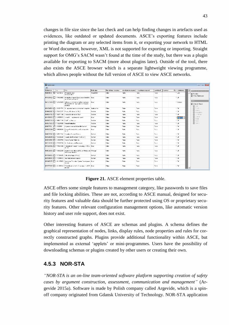
43
changes in file size since the last check and can help finding changes in artefacts used as
evidences, like outdated or updated documents. ASCE’s exporting features include
printing the diagram or any selected items from it, or exporting your network to HTML
or Word document, however, XML is not supported for exporting or importing. Straight
support for OMG’s SACM wasn’t found at the time of the study, but there was a plugin
available for exporting to SACM (more about plugins later). Outside of the tool, there
also exists the ASCE browser which is a separate lightweight viewing programme,
which allows people without the full version of ASCE to view ASCE networks.
Figure 21. ASCE element properties table.
ASCE offers some simple features to management category, like passwords to save files
and file locking abilities. These are not, according to ASCE manual, designed for secu-
rity features and valuable data should be further protected using OS or proprietary secu-
rity features. Other relevant configuration management options, like automatic version
history and user role support, does not exist.
Other interesting features of ASCE are schemas and plugins. A schema defines the
graphical representation of nodes, links, display rules, node properties and rules for cor-
rectly constructed graphs. Plugins provide additional functionality within ASCE, but
implemented as external ‘applets’ or mini-programmes. Users have the possibility of
downloading schemas or plugins created by other users or creating their own.
4.5.3 NOR-STA
“NOR-STA is an on-line team-oriented software platform supporting creation of safety
cases by argument construction, assessment, communication and management” (Ar-
gevide 2015a). Software is made by Polish company called Argevide, which is a spin-
off company originated from Gdansk University of Technology. NOR-STA application

44
areas are compliance management, rating systems and assurance cases. For this thesis
only the assurance case extension was used and reviewed. Default version of the soft-
ware is web based and runs from the servers hosted by Argevide and it can be accessed
by the user’s web browser of choice. Other option is to buy a host licence and host
NOR-STA on your own servers. Argevide offers few kinds of licences for purchase
depending on the number of users and projects required by the buyer. (Argevide 2015a).
NOR-STA version 6.6, which was releases 13.1.2016, was used for this work. Software
is fully supported, updated and developed regularly. Argevide offered a free academic
licence for the review of the tool.
As said, NOR-STA is a software platform that integrates the processes of argument
construction, assessment, communication and management. It supports on-line team-
oriented working processes. (Argevide 2015a). “On-line” means that it is possible to use
NOR-STA just from web browser alone and access the tool from anywhere just with an
internet connection. NOR-STA supports the development of structured arguments,
which will have a text based tree-like structure with several dedicated node types:
claims, argumentation strategies with rationales, facts, assumptions, references, infor-
mation nodes and links. Main window of NOR-STA can be seen in Figure 22.
Figure 22. NOR-STA’s user interface (Argevide 2015b).
NOR-STA doesn’t support GNS or CAE. It uses its own argument structure called
TRUST-IT. The elements of TRUST-IT relate to basic assurance case elements of ISO
15026 as shown in Figure 23. NOR-STA’s argumentation strategy uses a claim sup-
ported by argumentation strategy which is then supported by a fact. Rather than using a
diagram to bring the structure to the safety case, like ASCE and Astah GSN above,
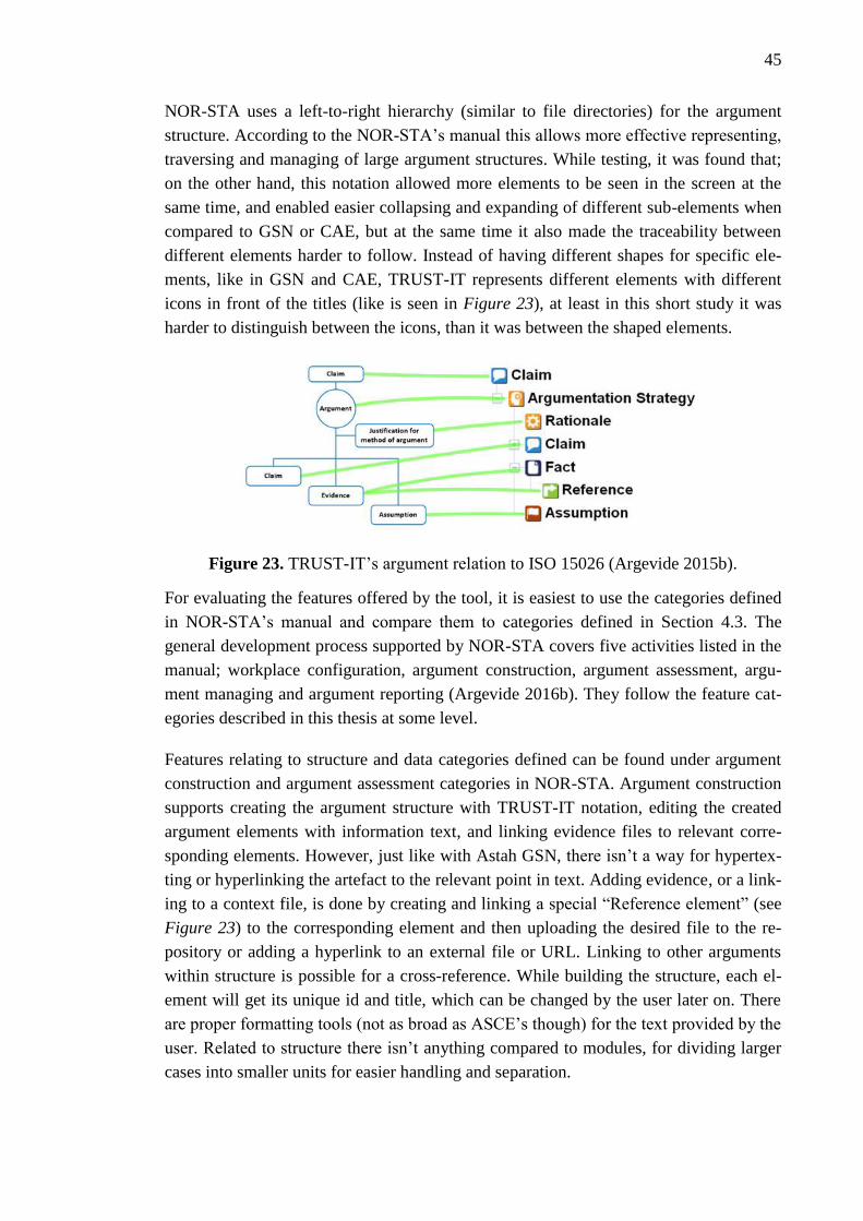
45
NOR-STA uses a left-to-right hierarchy (similar to file directories) for the argument
structure. According to the NOR-STA’s manual this allows more effective representing,
traversing and managing of large argument structures. While testing, it was found that;
on the other hand, this notation allowed more elements to be seen in the screen at the
same time, and enabled easier collapsing and expanding of different sub-elements when
compared to GSN or CAE, but at the same time it also made the traceability between
different elements harder to follow. Instead of having different shapes for specific ele-
ments, like in GSN and CAE, TRUST-IT represents different elements with different
icons in front of the titles (like is seen in Figure 23), at least in this short study it was
harder to distinguish between the icons, than it was between the shaped elements.
Figure 23. TRUST-IT’s argument relation to ISO 15026 (Argevide 2015b).
For evaluating the features offered by the tool, it is easiest to use the categories defined
in NOR-STA’s manual and compare them to categories defined in Section 4.3. The
general development process supported by NOR-STA covers five activities listed in the
manual; workplace configuration, argument construction, argument assessment, argu-
ment managing and argument reporting (Argevide 2016b). They follow the feature cat-
egories described in this thesis at some level.
Features relating to structure and data categories defined can be found under argument
construction and argument assessment categories in NOR-STA. Argument construction
supports creating the argument structure with TRUST-IT notation, editing the created
argument elements with information text, and linking evidence files to relevant corre-
sponding elements. However, just like with Astah GSN, there isn’t a way for hypertex-
ting or hyperlinking the artefact to the relevant point in text. Adding evidence, or a link-
ing to a context file, is done by creating and linking a special “Reference element” (see
Figure 23) to the corresponding element and then uploading the desired file to the re-
pository or adding a hyperlink to an external file or URL. Linking to other arguments
within structure is possible for a cross-reference. While building the structure, each el-
ement will get its unique id and title, which can be changed by the user later on. There
are proper formatting tools (not as broad as ASCE’s though) for the text provided by the
user. Related to structure there isn’t anything compared to modules, for dividing larger
cases into smaller units for easier handling and separation.
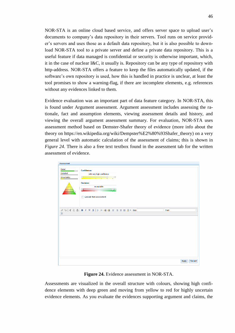
46
NOR-STA is an online cloud based service, and offers server space to upload user’s
documents to company’s data repository in their servers. Tool runs on service provid-
er’s servers and uses those as a default data repository, but it is also possible to down-
load NOR-STA tool to a private server and define a private data repository. This is a
useful feature if data managed is confidential or security is otherwise important, which,
it in the case of nuclear I&C, it usually is. Repository can be any type of repository with
http-address. NOR-STA offers a feature to keep the files automatically updated, if the
software’s own repository is used, how this is handled in practice is unclear, at least the
tool promises to show a warning-flag, if there are incomplete elements, e.g. references
without any evidences linked to them.
Evidence evaluation was an important part of data feature category. In NOR-STA, this
is found under Argument assessment. Argument assessment includes assessing the ra-
tionale, fact and assumption elements, viewing assessment details and history, and
viewing the overall argument assessment summary. For evaluation, NOR-STA uses
assessment method based on Demster-Shafer theory of evidence (more info about the
theory on https://en.wikipedia.org/wiki/Dempster%E2%80%93Shafer_theory) on a very
general level with automatic calculation of the assessment of claims; this is shown in
Figure 24. There is also a free text textbox found in the assessment tab for the written
assessment of evidence.
Figure 24. Evidence assessment in NOR-STA.
Assessments are visualized in the overall structure with colours, showing high confi-
dence elements with deep green and moving from yellow to red for highly uncertain
evidence elements. As you evaluate the evidences supporting argument and claims, the

47
arguments and claims gain the confidence of lower lever elements, meaning that if all
the evidence of a certain claim is rated high with confidence and belief corresponding
argument and claim will be as well. This is a very good and useful feature, which is not
found in the any of the other tool which was studied. Example of assessment coloured
structure is shown in Figure 25, it shows the green, yellow and red elements.
Figure 25. Assessment of argument on NOR-STA (Argevide 2015b).
Review, planning and management are supported in NOR-STA under workplace con-
figuration, argument management and argument reporting sections. Workplace configu-
ration includes features, which support configuration management. These include fea-
tures like access permissions and configuring the data repositories. Change management
in NOR-STA allows browsing of all the changes made in the argument, viewing argu-
ment version for a given date, and viewing the list of evidence changes and assessment
history. Change management enables also tracking of the corresponding user for mak-
ing any certain changes in the element. This is possible as NOR-STA supports team
based working on the tool. It has a multiuser environment with different roles available
(viewer, developer, assessor, editor, manager, and administrator). Everyone working on
the project will need to log in with their own credentials. Each of these roles can be set
the desired permissions as seen in Figure 26. NOR-STA ‘flags’ a warning sign about
incomplete or broken elements automatically. Argument management activity supports
configuration management features, like viewing version history and exporting and im-
porting argument structures. Argument reporting consists of print screens or change
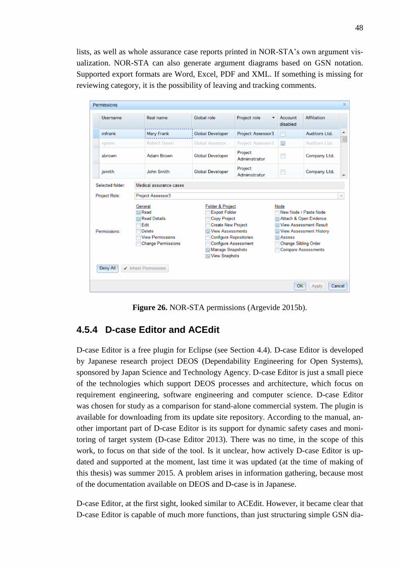
48
lists, as well as whole assurance case reports printed in NOR-STA’s own argument vis-
ualization. NOR-STA can also generate argument diagrams based on GSN notation.
Supported export formats are Word, Excel, PDF and XML. If something is missing for
reviewing category, it is the possibility of leaving and tracking comments.
Figure 26. NOR-STA permissions (Argevide 2015b).
4.5.4 D-case Editor and ACEdit
D-case Editor is a free plugin for Eclipse (see Section 4.4). D-case Editor is developed
by Japanese research project DEOS (Dependability Engineering for Open Systems),
sponsored by Japan Science and Technology Agency. D-case Editor is just a small piece
of the technologies which support DEOS processes and architecture, which focus on
requirement engineering, software engineering and computer science. D-case Editor
was chosen for study as a comparison for stand-alone commercial system. The plugin is
available for downloading from its update site repository. According to the manual, an-
other important part of D-case Editor is its support for dynamic safety cases and moni-
toring of target system (D-case Editor 2013). There was no time, in the scope of this
work, to focus on that side of the tool. Is it unclear, how actively D-case Editor is up-
dated and supported at the moment, last time it was updated (at the time of making of
this thesis) was summer 2015. A problem arises in information gathering, because most
of the documentation available on DEOS and D-case is in Japanese.
D-case Editor, at the first sight, looked similar to ACEdit. However, it became clear that
D-case Editor is capable of much more functions, than just structuring simple GSN dia-

49
grams. But, in the timeframe of this thesis, there weren’t enough time and information
available to fully study all the possible features offered in D-case Editor, especially re-
lating to monitoring a target system via parameters and input conditions. D-case Edi-
tor’s key features, listed in its the manual (D-case Editor 2013), are GSN diagram edi-
tor, GSN pattern library function, prototype type-checking function and consistency-
checking function. GSN Editor supports building general GSN diagrams from the basic
elements with all the extensions. The UI of D-case is shown in Figure 27.
Figure 27. User interface of D-case Editor.
GSN editor has the basic functions for creating a structured safety case, like defining the
structure by dragging the elements to the diagram and connecting them with links, very
much like all the other tools studied. Unfortunately, that was all it was found during the
testing to be available for defining the structured and planning activities. For data add-
ing category, there is a description box under each element for inserting data or hyper-
linking it to relevant sources; modules, files or URLs. Formatting the data is very lim-
ited, but user can set a few properties for each of the elements. The properties as shown
in Figure 28, they are a bit cryptic and same for each of the elements, and the true
meaning behind them was left as a mystery, as not enough information was found for
understanding them.
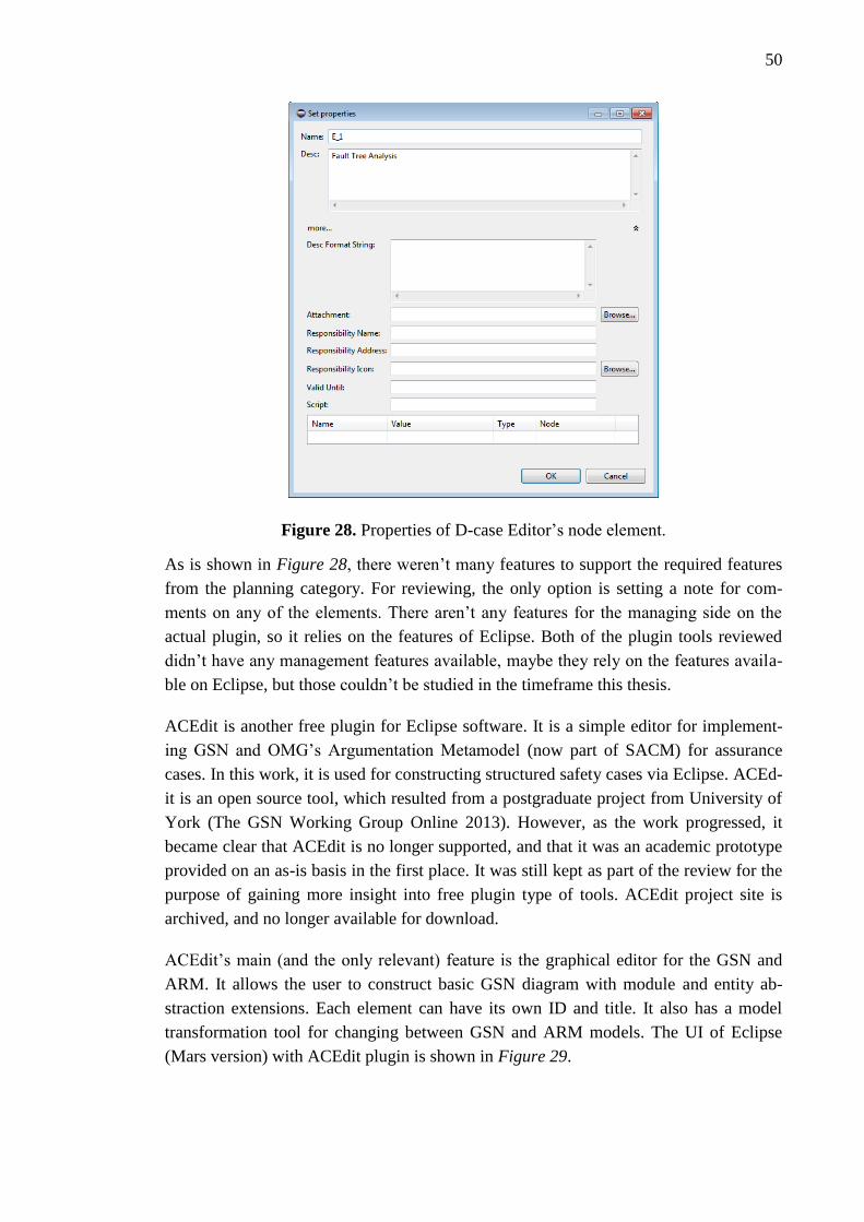
50
Figure 28. Properties of D-case Editor’s node element.
As is shown in Figure 28, there weren’t many features to support the required features
from the planning category. For reviewing, the only option is setting a note for com-
ments on any of the elements. There aren’t any features for the managing side on the
actual plugin, so it relies on the features of Eclipse. Both of the plugin tools reviewed
didn’t have any management features available, maybe they rely on the features availa-
ble on Eclipse, but those couldn’t be studied in the timeframe this thesis.
ACEdit is another free plugin for Eclipse software. It is a simple editor for implement-
ing GSN and OMG’s Argumentation Metamodel (now part of SACM) for assurance
cases. In this work, it is used for constructing structured safety cases via Eclipse. ACEd-
it is an open source tool, which resulted from a postgraduate project from University of
York (The GSN Working Group Online 2013). However, as the work progressed, it
became clear that ACEdit is no longer supported, and that it was an academic prototype
provided on an as-is basis in the first place. It was still kept as part of the review for the
purpose of gaining more insight into free plugin type of tools. ACEdit project site is
archived, and no longer available for download.
ACEdit’s main (and the only relevant) feature is the graphical editor for the GSN and
ARM. It allows the user to construct basic GSN diagram with module and entity ab-
straction extensions. Each element can have its own ID and title. It also has a model
transformation tool for changing between GSN and ARM models. The UI of Eclipse
(Mars version) with ACEdit plugin is shown in Figure 29.

51
Figure 29. User interface of ACEdit.
For adding the actual evidence data and artefacts to the structure, the choices are very
limited. Only possibility is writing under the ’description’ property (also seen in the
bottom of Figure 29). There is no support for any formatting options or even hyperlink-
ing. There are no features available for planning or management categories. For review-
ing, there are some model management features for the ACEdit; model validation and
in-place model transformation. However, they could not be tested, as they didn’t func-
tion or the instructions were unclear. It became clear, that ACEdit is created for GSN
demonstration purposes; it doesn’t have the required functions to support a structured
safety case from a real system point of view.
Both of the plugin tools offered the basic functions required to structure the outlines of a
structured safety case. Using them was complicated, as was getting them to work in the
first place. There is potential in D-case Editor, but it would require much deeper under-
standing behind the functions behind it to get them into good use. The tools are not at
the moment suited for larger scale safety assurance, at least not without a deep learning
curve. Both of the tools were missing out many of the features required. It has to be
said, that the author’s knowledge of Eclipse’s features was limited and in the scope of
this work there was no time to gain deeper insight into all the possibilities which could
be done with a deeper level of Eclipse knowledge. But for casual use, the Eclipse plugin
tools were complicated and cumbersome compared to standalone software reviewed
earlier.
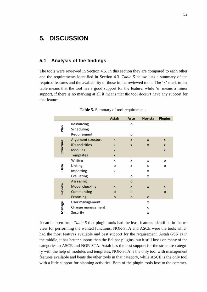
52
5. DISCUSSION
5.1 Analysis of the findings
The tools were reviewed in Section 4.5. In this section they are compared to each other
and the requirements identified in Section 4.3. Table 5 below lists a summary of the
required features and the availability of those in the reviewed tools. The ‘x’ mark in the
table means that the tool has a good support for the feature, while ‘o’ means a minor
support, if there is no marking at all it means that the tool doesn’t have any support for
that feature.
Table 5. Summary of tool requirements.
It can be seen from Table 5 that plugin tools had the least features identified in the re-
view for performing the wanted functions. NOR-STA and ASCE were the tools which
had the most features available and best support for the requirement. Astah GSN is in
the middle, it has better support than the Eclipse plugins, but it still loses on many of the
categories to ASCE and NOR-STA. Astah has the best support for the structure catego-
ry with the help of modules and templates. NOR-STA is the only tool with management
features available and beats the other tools in that category, while ASCE is the only tool
with a little support for planning activities. Both of the plugin tools lose to the commer-
Astah Asce Nor-sta Plugins
Resourcing o
Scheduling
Requirement o
Argument structure x x x x
IDs and titles x x x x
Modules x x
Templates x
Writing x x x o
Linking o x o o
Importing x x
Evaluating o x
Assessing o
Model checking x x x x
Commenting o o o
Exporting o o o
User management x
Change management o
Security x
Pla
nSt
ruct
ure
Dat
aR
evi
ew
Man
age
53
cial tools on most of the categories. It is clear that they cover only the very basic func-
tions of making a structured safety case.
Examination of the feature categories on the Table 5 reveals that planning and manage-
ment are the two least supported classes. Management activity in Section 4.2 and the
management feature category in Section 4.3 were identified and defined with a devel-
opment team and multiuser tool environment in mind. However, in the review, it was
discovered that four out of the five reviewed tools only supported a single user at a time.
The same idea of a safety case team and tool environment applied to the planning cate-
gory, which explains why both of those areas are so badly covered in Table 5. All of the
tools certainly needed more functionality and support for these two important catego-
ries. On the other hand, it was clear, that the structure and data categories were covered
the best by the tools in question. All of them allowed building a safety case structure
using some notation and inserting the required data in some form. There were differ-
ences, between each of the tools, in the way this was done. In the worst cases it was just
plain text straight to the element, but usually hyperlinking was possible too. In the best
case, there were proper text formatting options with hypertexting and tables. Good sup-
port for these two categories was expected, as the tools were, at least in paper, marketed
and designed to support structured development of safety cases which in the simplest of
definitions is just that; building the structure and inserting the required evidence.
Based on testing, it became clear that Astah GSN should be used for illustrating small
scale diagrams and creating compact structured safety cases with GSN notation for
small and rather simple systems or components. All of that, it does really well. Howev-
er, it is missing features in the management and planning categories to be used as of a
safety case tool for larger and more complex systems or heavy industrial use. The struc-
tured safety case approach developed is meant for creating more commercial and scien-
tific safety justification that Astah GSN is able to offer at the moment. It only supports
one user, with no user roles available and no configuration management features at all.
User can insert free text, but there is no way for formatting, hypertexting or even hyper-
linking from the text field. The hyperlinking must be done from another menu and there
isn’t a way for pointing the hyperlink for any certain part of the text. Astah GSN also
doesn’t have a way for assessing the significance or confidence of the inserted or linked
evidence or the plausibility of the used arguments. Compared to NOR-STA and ASCE,
Astah GSN doesn’t have much to offer in the feature side, it falls a bit short on every
category. However, it is good for what it is meant to be, a lightweight and simple tool
for building simple GSN diagrams, also it supports the GSN standards better than any of
the other tools reviewed, and it has good importing and exporting features for the deliv-
erables. For the reasons explained above, Astah GSN can’t be recommended as the
practical tool option searched in this thesis.
ASCE has been longer in the development, and it shows. Compared to Astah GSN and
NOR-STA, ASCE is more complex and required more studying and testing to get used

54
to. But in compensation, it offers more complex features and functions to work with. In
the feature side ASCE’s strengths are strong data providing and structure layout, the
proper text editor and the hyperlinking and –texting possibilities, which offered good
support for writing the safety argumentation and providing the traceability with text and
links. One thing missing from ASCE is the importing function for XMI. It is the only
tool with light planning abilities, with the possibility for setting up a very simple re-
sourcing and a scheduling in the node properties settings. How these settings could be
used, to easily plan the activities of filling content and distributing responsibilities,
without a multiuser or role support found in the tool, is still unknown. ASCE has the
potential for handling more than just simple systems with good structure and data fea-
tures, but as it is not supporting modules or otherwise straight up splitting overgrown
networks to easier manageable ones, it will have problems. Other weakness is the lack
of configuration management features, as there are none. Biggest advantage of ASCE
could be the support for creating and downloading user made content, which could help
covering some weaknesses found in the tool. But it is highly dependable on active users
and their enthusiasm of creating content for it. At the moment there are some plugins
available, but nothing too decisive. Overall, ASCE is a tool supporting creation of the
structured safety case at notable level, yet it is not the best possible choice.
NOR-STA’s difference to the other tools reviewed was the different UI and online-
team-based approach to the safety case. It also seems to be the most innovative in
among the assurance/safety case tools reviewed, as it tries to bring in these essential
software features known from other popular software. Even though the user interface
differs from the somewhat “standard” diagram view, the basic principles of the structur-
ing the safety case are the same. NOR-STA’s different user interface works, at first it
doesn’t look as simple as a diagram structure of CAE or GNS notations, but after a
while the similarities with standard PC file directories make it seem logical. However, it
is impossible to say after the testing, whether it is better or worse than the diagram
structure. Both do their work, but both will still have difficulties at the moment with
large systems. TRUST-IT allows better handling of such systems as it is now, but it
doesn’t allow modules or sub-cases which seem to be way of going towards complex
systems. As NOR-STA is browser and online based, it obviously works with any plat-
form, this is a huge advantage. Like the other commercial tools, it has a customer sup-
port and updates for fixes and new content. NOR-STAs strengths are its design for
team-oriented and web based approach, which supports multiple user for a single safety
case, as well as setting different roles and access rights for the users of the case. Other
features, which are NOR-STA’s strengths, are the change-tracking and the effective
build-in evidence evaluation function. It is also only tool for having a feature for data
storing and repositories. Out of tools reviewed, NOR-STA is closest to the tool to fill
the requirements set in Section 4.3. It is not perfect however, it’s clearly lacking fea-
tures in the planning and review category, without any resourcing, scheduling or com-
menting features found in the tool at the moment.

55
Testing and studying the Eclipse plugins ACEdit and D-case Editor, after using the
commercial tools, made the differences between them become clear. Unfortunately,
plugins lose on the feature side to commercial tools on all categories, except in building
the diagram with GSN notation. Both of the plugins have a simple diagram building
functions that can do the same as commercial tools at some level. Like using the ele-
ments from GSN and connecting them together, as well as naming them and writing
textual description in them, however, without any formatting options. There weren’t
found anything to support the planning, review or management categories on these
tools, except for a model checking feature, which looks for illegal connections between
the GSN elements. The plugins are rather difficult to use, as the default Eclipse UI
doesn’t guide the user at all. It became clear that ACEdit and D-case Editor didn’t have
the required features for developing the structured safety case. The result would be dif-
ficult to follow and not bring the wanted structure and traceability. In the review, D-case
Editor showed some promising potential, but for the reasons explained in the review,
the knowledge fully understanding the tool couldn’t be gained during the research
phase. Based on these reason, the plugin tools can’t be recommended for use.
5.2 Conclusions from the review
Out of the tools reviewed, NOR-STA has the best support for the features required for
the development process of a structured safety case outlined in Section 4.2. Its strengths
are in the data and management feature categories, which have the best support out of
the tools reviewed. Especially its team orienteered and online-based management sys-
tem is the best of all the other tools reviewed. Other useful features are the support for
the use of data repository and user management and roles. Another advantage which
puts it above the other tools is the integrated assessment function, which allows user to
assess the evidence inserted. NOR-STA is the best choice out of the tools reviewed.
Unfortunately, NOR-STA is not the perfect tool overall for a structured safety case de-
velopment. It is missing support to few critical areas which were determined useful. Just
like the other four reviewed tools, NOR-STA doesn’t have required support for the
planning and reviewing features and it doesn’t have a way of using modular safety cases
for larger and more complex systems. On a side note; it would be useful if the TRUST-
IT would be more congruent with the elements from assurance case standard ISO
15026. Although the textual left-to-right hierarchy allows more effective representing,
traversing and managing of large argument structures, it makes the structure and the
traceability a bit harder to follow. This leads to the question of the superiority of the
different notations used by the tools. All the notations have the difficulty of allowing
large scale structures and still keeping the outcome easy to follow and manage. This
thesis can’t answer to that question either, but it can be said that none of tools were have
managed to solve that problem either.

56
If it is for some reason compulsory to use GSN or CAE notation for the safety case,
then ASCE is the choice of the tools reviewed. Overall, it is the second best choice for
the tool option. Compared to NOR-STA, it has better features for the text formatting
and writing the argument and inserting the evidences for the case. It is also the only tool
with a plugin support. ASCE’s weaknesses are on the management and team work side.
At least in the tool review, there weren’t found any features relating to configuration
management or multiuser support with different roles in ASCE. Another weakness
compared to NOR-STA is the lack of assessment features.
Third reviewed commercial tool was Astah GSN. In the features side it loses to NOR-
STA and ASCE. However, it is a neat lightweight tool for building compact GSN dia-
grams, and it also has the best support out of the tool reviewed for GSN standard and to
ISO 15026. For the development process outlined, it doesn’t have enough support. The
plugins D-case Editor and ACEdit can’t be recommended to be used for developing a
structured safety case. They don’t have the features required.
The structure category was the best supported category among all of the tools, but it
only relied on the user to build a proper argument structure, there was no help given
from the tools for the layout or the content of the claims or arguments. The idea of tem-
plates or guiding for better structure was missing from all of the tools. Only in Astah
GSN it was possible to even reuse old saved structures. This certainly would require
more support from the tools. On the other hand, the planning category was supported
the least. The idea behind planning was to find features which would help and guide the
user preparing for the development process. One example of planning feature on the
tools could be some sort of guiding mechanism for the user to write a better arguments
and claims, maybe offering a way for semi-formal language or a support for claim and
argument libraries. As mentioned, only ASCE had a few options available for planning
the resources for the project, and these were only meant as reminders rather than re-
quests.
Management section was another category with a low level of support. Only NOR-STA
had really focused on the management of users and safety, but not so much on the con-
figuration management. But the other tools didn’t have anything available for providing
multi user or user role support. The lack of management features really impedes to us-
ing of the tools for industrial and large scale use. For the review section, there were a
few features available on the tools, but the possibilities realized were very limited. None
of the tools had really focused on the matter. Most of the tools had a simple comment-
ing possibility and all of them had a basic model checking tool, which inspects the
model for illegal connections and in some cases for invalid or outdated links. Important
attribute of the reviewing category was the exporting requirement, which was meant for
producing reports for justifying the safety for the reviewer, while possibly complying
with their requirements.
57
None of the tools had a possibility of producing a specified safety reports, the commer-
cial tools had options for exporting the whole diagram in a picture and Astah and NOR-
STA as XMI. In future, tools could be a way of automating the development of safety
analysis reports (SARs, see Section 2.3.2), if they could produce the correct type of
documents or exports. At the moment, the tools evaluated have a limited ability to do
so. According to STUK, the appearance of the safety demonstration is free, as long as it
is understandable and satisfies all the relevant requirements from YVL guides. STUK is
moving towards of some degree of electronic submission of qualification and licencing
material, so a tool produces material could definitely be an option.
As any of the tools searched, found and tested didn’t offer all the features required,
maybe developing a completely new tool to support all the features that were found to
be necessary and relevant could be a feasible option. Section 4.3 would offer a good
foundation for the design of such tool. Of course that would require even deeper re-
search in to the required features, but the foundation is laid in this work. It could be the
way forward at the moment; it could offer new business ideas as well, as there still is
improvement to be had in the tool front, at least based on the results of this thesis.
There was no time to develop this idea any further in the scope of this thesis, but it is
still a worthy option.
5.3 About safety cases and tools
To summarise the ideas considered throughout this thesis, this section includes few
thoughts, which were arisen about the safety demonstration, structured safety case and
software tools in general. The safety demonstration process in complex projects, such as
constructing a nuclear power plant, produces a considerable number of safety related
documents. Like mentioned in Section 2.1, the safety justification should be logically
unarguable, unbiased, comprehensive, transparent and accessible to all relevant parties.
All this brings forth challenges for creating a safety demonstration artefact, which com-
plies with all of those requirements. So, one important feature of the software tools is
combining together the safety requirements, the safety argument and the body of evi-
dence. At the moment, these can exist as separate documents, but an electronically pro-
duced and maintained structured safety case could offer the means of linking these arte-
facts together. It wouldn’t matter whether the documents would come from different
stakeholders and be under the control of different configuration management systems.
However, this would also require the data to in some standard form. Nowadays, differ-
ent types of safety related documents are generated by a special purpose software tools
and maintained electronically, so there is an obvious environment for safety case tool
for combining all this into one artefact. Maybe this could be the nuclear safety case?
Fortunately, as discovered, tools for creating safety cases are available. First, these tools
were mostly add-ons or plugins for popular modelling tools such as MS Visio or Eclipse
(like the plugins reviewed), but at the moment, there are also available commercial

58
software, which are just focused on creating safety cases. Although they might not be
fully capable of handling an industrial scale, fully system extensive safety management
and justification, the idea is there, and hopefully developing towards this goal.
Proper software tool could allow effectively managing and maintaining safety, it would
offer a way to gather all the latest versions of artefacts that form the safety material and
its context easily acceptable anywhere by any relevant stakeholder. With a proper tool
support, the task of summarising the safety case in order to generate the safety reports
required at key project decision points could be easier and less time-consuming. (Ye &
Cleland 2012). Of course the tool only gives the possibility of doing this, but in the end
it is up to the user for writing the safety case and actually making it a good safety
demonstration. One notable point, not really introduced in this work, is that any of the
tools didn’t offer any way of using controlled or formal language, which would help all
readers understand the arguments in the same way by restricting the grammar and vo-
cabulary in order to reduce or eliminate ambiguity and complexity. Writing the safety
case in such a way might the future of producing arguments and claims of safety
demonstrations. (Denney & Ganesh 2015).
However, preparing a safety case gets more difficult when the system-of-interest is
complex and large. The diagram structures, which the tools offer at the moment, will
grow more complex and bigger as well, even too big handle and will lose the benefits of
structured safety case, while easily becoming too complex or difficult to follow and no
real alternative is given to current practices. Currently, this could be scoped with divid-
ing bigger systems down into sub-cases (modules), maybe even to component level. In
future, safety case could be compiled out of predeveloped modules, which are done by
different teams in-house or third parties (suppliers, TSOs). They do not have the fea-
tures yet to manage large plant or system level assurance case without Tools available
right now are best for component and sub-system level assurance cases. Another major
problem is the lack of reusable building blocks, which would help users developing cas-
es in a more efficient and systematic manner.
5.4 Validity and reliability of the results
The challenges were finding the right requirements for the tools, finding and selecting
the tools for evaluation and performing the tool review with limited time and
knowledge. In this section it is discussed, whether the results from Chapter 4 corre-
sponded to the goals and whether this thesis succeeded to answer its objectives. Validity
is the extent to which the results are well-founded and corresponded to the require-
ments. Reliability describes the confidence that the gained results are correct.
First goal was to describe a context and the terms used for the safety case in the justifi-
cation of nuclear I&C systems. The description is only a conceptual model and built
from the viewpoints and knowledge coming from VTT and available literature and

59
guides concerning licencing and qualification processes. If it were important to create
more specific model around the nuclear safety case, more thorough research is recom-
mended, as well as gaining more feedback from other stakeholders involved in the pro-
cess. For increasing the reliability of the resulting description, it tried to take into ac-
count only the most obvious parts of the current practices and build just a conceptual
interpretation. This way it was possible to try to avoid factual errors and confusion. The
most important functions of the description was to clarify the used terms and work as a
background for the structured safety case development process defined in Section 4.2.
Second goal was answering to the question how is a structured safety case developed.
Producing the right process was a difficult task, as information of an actual develop-
ment process was difficult to find. Information from STUK and knowledge at VTT
helped to create outlines for the process sufficient for the needs of this work. It is not an
accurate description, but it accomplishes setting a background for the feature require-
ments. It leans on the defined stakeholders, use cases and user roles for its validity.
Those were identified from the current practises of the nuclear domain in Finland and
abroad. Some of the concepts were taken from literature to combine the safety case as a
part of the process.
Third goal was defining the requirements for tool features. Validity of the tool require-
ments rely on the validity of the development process. As the development process is
only outlines, the tool requirements should only be understood as a suggestive ap-
proach. The features gathered were, however, sufficient for the goals of this thesis and
gave the wanted requirements for the tool review. It was identified that the tool re-
quirements shouldn’t be too in depth, as their availability on the tools could not be veri-
fied. One part of the results was the tool search. It was not thorough, but the most obvi-
ous options were covered by literature and internet search for assurance/safety case
tools.
Last goal was evaluating the suitability of safety case tools. The tool review answers to
that question based on the results gained from the previous goals. Based on the tool re-
view it was possible to give a valid opinion about the tool options for the development
of structured safety case. The validity of the tool review process relied on the skills of
the author to understand the basic, and sometimes rather advanced, functions of the
tools in a short time frame. Hence, the tool feature requirements were set to suitable
generalized level to avoid the demand of deep knowledge of the system and tools. The
reliability of the results depends on the author’s correct understanding of the tool manu-
als and actual tests with the tools. The author is quite confident about them, but takes
responsibility of any errors made during the descripting and testing the tools.
60
5.5 Implications
Practical implications of the results are created by the tool requirements and the tool
review. The current level of the safety case tool support was interesting for VTT and
other stakeholders. It helps planning the future actions concerning the use of software
tools as a way of presenting or assessing the safety demonstration of nuclear I&C. But
as was concluded from the analysis of the tool review, none of the evaluated tools were
suitable at the desired level support for the feature categories. This means that the
search and studying of the tool is recommended to be continued as new tools are surely
being developed and current ones being updated. However, it became clear that the po-
tential for tool support exists. The tool review and the related development process of
the structured safety case offers one insight into utilizing the software tool in the justifi-
cation.
Scientific implications of the results are limited as the work rather introduced and tried
to clarify terminology around the safety case and nuclear domain. The importance of
nuclear safety case was to introduce the terms nuclear safety case, safety demonstration
and structured safety case as part of nuclear I&C justification. Hopefully they can also
help with the confusion around the safety demonstration and qualification processes
(Valkonen et al. 2016). One source of confusion comes with the undeveloped terminol-
ogy, and the nuclear safety case, safety demonstration and structured safety case de-
scription gives one approach to the subject. It was still unclear, whether it will be useful
now or later in the future. However, it will still need refining and expanding to be really
useful in depicting the wanted practices.
The development of structured safety case tools will continue, and the current tools
evolve with new updates and features. Legislation and standards concerning safety justi-
fication and the safety cases are most likely changing to meet standards of the new chal-
lenges brought by the introduction of complex digital I&C systems. This opens new
approach possibilities for the safety case tools as well. So, the development of the safety
case tools should be followed, for the current as completely new tools as well.
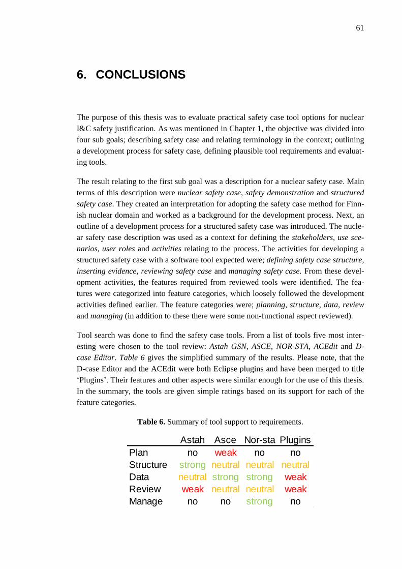
61
6. CONCLUSIONS
The purpose of this thesis was to evaluate practical safety case tool options for nuclear
I&C safety justification. As was mentioned in Chapter 1, the objective was divided into
four sub goals; describing safety case and relating terminology in the context; outlining
a development process for safety case, defining plausible tool requirements and evaluat-
ing tools.
The result relating to the first sub goal was a description for a nuclear safety case. Main
terms of this description were nuclear safety case, safety demonstration and structured
safety case. They created an interpretation for adopting the safety case method for Finn-
ish nuclear domain and worked as a background for the development process. Next, an
outline of a development process for a structured safety case was introduced. The nucle-
ar safety case description was used as a context for defining the stakeholders, use sce-
narios, user roles and activities relating to the process. The activities for developing a
structured safety case with a software tool expected were; defining safety case structure,
inserting evidence, reviewing safety case and managing safety case. From these devel-
opment activities, the features required from reviewed tools were identified. The fea-
tures were categorized into feature categories, which loosely followed the development
activities defined earlier. The feature categories were; planning, structure, data, review
and managing (in addition to these there were some non-functional aspect reviewed).
Tool search was done to find the safety case tools. From a list of tools five most inter-
esting were chosen to the tool review: Astah GSN, ASCE, NOR-STA, ACEdit and D-
case Editor. Table 6 gives the simplified summary of the results. Please note, that the
D-case Editor and the ACEdit were both Eclipse plugins and have been merged to title
‘Plugins’. Their features and other aspects were similar enough for the use of this thesis.
In the summary, the tools are given simple ratings based on its support for each of the
feature categories.
Table 6. Summary of tool support to requirements.
Astah Asce Nor-sta Plugins
Plan no weak no no
Structure strong neutral neutral neutral
Data neutral strong strong weak
Review weak neutral neutral weak
Manage no no strong no

62
NOR-STA was the tool with the most extensive support to the feature categories out of
the tools reviewed. However, as was concluded from the tool review analysis, none of
the tools supported all of the feature categories at a sufficient level. Most lack of support
was identified among the features relating to planning, managing and reviewing the
safety case. Also presenting and managing of large and complex systems with compli-
cated claim, argument and evidence structure could be enhanced on all of the tools to
allow more comprehensive and manageable document. On the other hand, decent sup-
port was found on data and structure categories, for which all of the tools had at least
moderate support. Results implicated that the reviewed safety case software tools are
not ready yet for large scale industrial use for the justification of instrumentation and
control nuclear power plants. The final answer to the research question was that none of
the tools reviewed can as such be recommended to be used by VTT or any other stake-
holders at the moment.
This thesis was an initial approach to the safety case software tools. Development of the
practical tool options is recommended to be followed in the future as well, if a proper
software tool needs to be found. Further research would, however, be required to find
more exact and precise tool requirements. It would require deeper knowledge of the
needs of the stakeholders, and of the licensing and the qualification processes. Tool fea-
ture categories and the development process of the structured safety case was not an
exact model or a perfect background for identifying the tool requirements. Many of the
elements were taken as a “best guess” basis and relying to relevant guides and stand-
ards, rather the actual processes happening in-between the stakeholders. Another source
of improvement and an area needing further research is the tool evaluation. The tool
review was done in a limited time frame. To get a better view, even on the current tool
situation, it would definitely be required to spend more time on searching for relevant
tools and learning their features on a deeper level. This revealed to be one of the biggest
challenges of this thesis, i.e. finding the suitable tools and learning their features in a
short time.
However, it became clear that the potential for tool supported safety case development
exist. The tool review and the related development process of the structured safety case
offers one insight into utilizing the software tool in the justification. Even though the
software tool support seems to be yet incomplete, more rigour would be needed for the
safety justification, maybe it could be done with the safety case approach. In the digital-
izing world, developing and documenting the safety demonstration with advanced tool
support, could definitely be the step forward.
63
REFERENCES
Adelard. 2004. ASCAD – Adelard Safety Case Development Manual, First Published
1998 by Adelard, Drysdale Building, London EC1V 0HB, ISBN 0 9533771 0 5
Adelard. 2015a. Claims, Arguments and Evidence (CAE). Webpage, accessed
13.10.2015. Available: http://www.adelard.com/asce/choosing-asce/cae.html
Adelard. 2015b. Goal Structuring Notation (GSN). Webpage, accessed 9.10.2015.
Available: http://www.adelard.com/asce/choosing-asce/gsn.html
Adelard. 2016. Choosing ASCE. Webpage, accessed 8.3.2016. Available:
http://www.adelard.com/asce/choosing-asce/index.html
Alanen, J. & Salminen, K. 2016. Systems Engineering Management Plan template - V1.
Research report VTT-R-00153-16, 81 p. Available:
http://www.vtt.fi/inf/julkaisut/muut/2016/VTT-R-00153-16.pdf
Argevide. 2015a. Assurance case. Webpage, accessed 8.3.2016 Available:
https://www.argevide.com/en/products/assurance_case
Argevide. 2015b. User’s Manual: What is NOR-STA? Webpage, accessed 8.3.2016.
Available: https://www.argevide.com/en/support/nor-sta/manual/introduction/
whatisnorsta
Bishop, P. & Bloomfield, R. 1998. A Methodology for Safety Case Development. Pro-
ceeding of the Sixth Safety-critical Systems Symposium. Birmingham, UK. Feb 1998,
Felix Redmill and Tom Anderson (eds), Springer, 1998 ISBN 3-540-76189-6. Availa-
ble: www.adelard.com/papers/sss98web.pdf
Change Vision. 2015. Astah GSN Start Guide. Version 2. Available:
https://s3.amazonaws.com/cdn.astah.net/resources/Astah+GSN+Start+Guide.pdf
Change Vision. 2016. Astah GSN. Webpage, accessed 1.2.2016. Available:
http://astah.net/editions/gsn
Common Position. 2014. Licensing of safety critical software for nuclear reactors.
Common position of international nuclear regulators and authorised technical support
organisations. Revision 2014. 165 p.
Defence Standard 00-56 – Safety Management Requirements for Defence Sys-
tems.MOD, issue 4 June 2007. Available:
http://www.skybrary.aero/bookshelf/books/344.pdf
64
Denney, E., Ganesh, P. & Pohl, J. 2012. AdvoCATE: An Assurance Case Automation
Toolset. Available: ti.arc.nasa.gov/m/profile/edenney/papers/sassur2012.pdf
Denney, E & Ganesh, P. 2015. Towards a Formal Basis for Modular Safety Cases.
SAFECOMP 2015, LNCS 9337, pp. 328–343, 2015.
Eclipse Foundation. 2016. Eclipse 4.5 (Mars). Webpage, accessed 21.3.2016. Available:
https://www.eclipse.org/downloads/
Elforsk. 2013. Safety Demonstration Plan Guide A general guide to Safety Demonstra-
tion with focus on digital I&C in Nuclear Power Plant modernization and new build
projects. Elforsk rapport 13:86, 63 p. Available:
www.elforsk.se/Rapporter/?download=report&rid=13_86_
Eurocontrol. 2006. Safety Case Development Manual edition 2.2. DAP/SSH/091. 13
November 2006. European Air Traffic Management.
GSN Community Standard Version 1. 2011. Origin Consulting Limited. York. Availa-
ble: http://www.goalstructuringnotation.info/documents/GSN_Standard.pdf
IEC 61513. 2011. Nuclear power plants – Instrumentation and control important to safe-
ty – General requirements for systems.
IAEA. 2002a. Safe and effective nuclear power plant life cycle management toward
decommissioning. IAEA-TECDOC-1305. International Atomic Energy Agency. Vienna
2002. Available: http://www-pub.iaea.org/MTCD/publications/PDF/te_1305_web.pdf
IAEA. 2002b. Solutions for cost effective assessment of software based instrumentation
and control systems in nuclear power plants – Report prepared within the framework of
the Technical Working Group on Nuclear Power Plant Control and Implementation.
IAEA-TECHDOC-1328. International Atomic Energy Agency. Vienna 2002. Availa-
ble: http://www-pub.iaea.org/MTCD/publications/PDF/te_1328_web.PDF
IAEA. 2007. IAEA safety glossary, terminology used in nuclear safety and radiation
protection. 2007 edition. International Atomic Energy Agency. Vienna 2007. Available:
http://www-pub.iaea.org/mtcd/publications/pdf/pub1290_web.pdf
IAEA. 2009. Implementing digital instrumentation and control systems in the moderni-
zation of nuclear power plants. IAEA Nuclear Energy Series. No. NP-T-1.4. Interna-
tional Atomic Energy Agency. Vienna 2009. Available:
http://pub.iaea.org/books/IAEABooks/8057/Implementing-Digital-Instrumentation-and-
Control-Systems-in-the-Modernization-of-Nuclear-Power-Plants

65
IAEA. 2010. Licensing process for nuclear installations, specific safety guide, IAEA
safety standard series. No. SSG-12. International Atomic Energy Agency. Vienna 2010.
Available: http://www-pub.iaea.org/MTCD/publications/PDF/Pub1468_web.pdf
IAEA. 2011. Core knowledge on instrumentation and control systems in nuclear power
plants. IAEA Nuclear Energy Series No. NP-T-3.12. International Atomic Energy
Agency. Vienna 2011. Available: http://www-pub.iaea.org/ books/IAEABooks/8490/
Core-Knowledge-of-Instrumentation-and-Control-Systems-in-Nuclear-Power-Plants
IAEA. 2015a. About Us. International Atomic Energy Agency. Webpage, accessed
19.10.2015. Available: https://www.iaea.org/about
IAEA. 2015b. The IAEA Mission Statement. International Atomic Energy Agency .
Webpage, accessed 19.10.2015. Available: https://www.iaea.org/about/mission
IAEA 2015c. Long term structure of the IAEA Safety Standards and current status. Sep-
tember 2015. International Atomic Energy Agency. Available: http://www-
ns.iaea.org/committees/files/CSS/205/status.pdf
IAEA. 2016. Nuclear Power Engineering. Instrumentation and Control Technologies.
International Atomic Energy Agency. Webpage, accessed 17.3.2016. Available:
https://www.iaea.org/NuclearPower/IandC/
IEEE/ISO 15026-1:2013. IEEE Standard Adoption of Systems and software engineer-
ing – Systems and software assurance – Part 1: Concepts and vocabulary. IEEE Com-
puter Society, New York, USA, 2014.
IEEE/IEC/ISO 15288:2015. Systems and software engineering – System life cycle pro-
cesses. Switzerland, 2015.
ISO 26262: 2011. Road vehicles – Functional safety. International Standardization Or-
ganization.
Johansson, M. 2015. Senior Inspector. Radiation and Nuclear Safety Authority STUK.
Helsinki. Interview 13.11.2015
Kelly, T. 1998. Arguing safety – A systematic approach to managing safety cases. Dis-
sertation. University of York. Available: http://www-users.cs.york.ac.uk/tpk/tpkthe
sis.pdf
Kelly, T. & Weaver, R. 2004. The Goal Structuring Notation – A Safety Argument No-
tation. Department of Computer Science and Department of Management Studies, Uni-
versity of York, York, UK. Available: http://www-users.cs.york.ac.uk/tpk/dsn2004.pdf

66
Netkachova, K; Netkachov, O & Bloomfield, R. 2015. Tool Support for Assurance Case
Building Blocks. SAFECOMP 2015 Workshops, LNCS 9338, pp. 62–71, 2015.
Nevalainen, R. & Varkoi, T. 2015. Requirements for an extended process assessment
model in systems and safety engineering. FiSMA report 2015-1. First draft. 49p.
Nuclear Energy Act. L 11.12.1987/990. Edilex. Available: http://plus.edilex.fi
/stuklex/en/lainsaadanto/19870990?toc=1
Nuclear Energy Degree. VNa. 12.2.1988/161. Edilex Available:
plus.edilex.fi/stuklex/en/lainsaadanto/19880161
ONR. 2013. The purpose, scope, and content of safety cases. Office for Nuclear Regula-
tion (ONR, an agency of HSE), guide NS-TAST-GD-051 rev. 3, 26 p. Available at:
http://www.onr.org.uk/operational/tech_asst_guides/ns-tast-gd-051.pdf
D-Case Editor. 2013. D-case Editor User’s manual. The University of Electro-
Communications, Nagoya University. 2013. Available http://www.dimensions-
japan.org/dcase/pdf/DCaseEditorUsersManual100.pdf
SACM. Structured Assurance Case Metamodel. Version 1.1. Object Management
Group. 2015. Available: http://www.omg.org/spec/SACM
Software Engineering Institute. 2015. Assurance Cases. Carnagie Mellon University.
Webpage. Accessed 5.10.2015. Available: http://www.sei.cmu.edu
/dependability/tools/assurancecase/
STUK. 2010. Finnish report on nuclear safety - Finnish 5th national report as referred to
in Article 5 of the Convention on Nuclear Safety. Radiation and Nuclear Safety Author-
ity. STUK-B 120, 86 p.
STUK. 2015a. Regulatory Guides on nuclear safety (YVL). Webpage, accessed
29.10.2015. Radiation and Nuclear Safety Authority. Available:
http://www.stuk.fi/web/en/regulations/stuk-s-regulatory-guides/regulatory-guides-on-
nuclear-safety-yvl-
STUK. 2015b. Regulatory control of facility project. Webpage, accessed 21.10.2015.
Radiation and Nuclear Safety Authority. Available: http://www.stuk.fi/web/en/stuk-
supervises/nuclear-safety/stuk-s-duties-in-the-supervision-of-nuclear-safety/regulatory-
control-of-facility-projects
Dawson, T. 2013. Assurance cases in planning and execution of NASA IV&V projects.
TASC, Test Assessing Secondary Completion. Available:
http://www.nasa.gov/sites/default/files/02-08_assurance_cases_in_nasa_ivv_projects.
pptx

67
Teollisuuden Voima Oyj. 2015a. Nuclear energy legislation. Webpage, accessed
5.10.2015. Available: http://www.tvo.fi/Nuclear%20energy%20legislation
Teollisuuden Voima Oyj. 2015b. Safety. Webpage, accessed 28.10.2015. Available:
http://www.tvo.fi/Safety2
Teollisuuden Voima Oyj. 2015c. Safety features and systems. Webpage, accessed
28.10.2015. Available: http://www.tvo.fi/Safety%20features%20and%20systems
The GSN Working Group Online. 2013. Assurance Case Editor (ACEdit). Webpage,
accessed 24.3.2016. Available: http://www.goalstructuringnotation.info/archives/268
Tommila, T. & Alanen, J. 2015. Conceptual model for safety requirement specification
and management in nuclear power plants. VTT Technology 238. VTT, Espoo 2015.
Available: http://www.vtt.fi/inf/pdf/technology/2015/T238.pdf
Tommila, T., Savioja, P. & Valkonen, J. 2014. Role of requirements in safety demon-
strations. Version 2, 31.1.2014. Working report. SAREMAN project. SAFIR2014.
Tommila, T. & Papakonstantinou, N. 2016. Challenges in defence in depth and I&C
architectures. Research report VTT-R-00090-16. VTT 2016. Available:
http://www.vtt.fi/inf/julkaisut/muut/2016/VTT-R-00090-16.pdf
Valkonen, J., Tommila, T., Linnosmaa, J. & Varkoi, T. 2016. Safety demonstration of
nuclear I&C – an introduction. SAUNA Task 3.1 report. Research report VTT-R-
00167-16. VTT, Espoo 2016. Available: http://www.vtt.fi/inf
/julkaisut/muut/2016/VTT-R-00167-16.pdf
World Nuclear Association. 2015. Nuclear Power Reactors. Webpage, accessed
27.10.2015. Available: www.world-nuclear.org/info/Nuclear-Fuel-Cycle/Power-
Reactors/Nuclear-Power-Reactors/
World Nuclear Association. 2014. Physics of Uranium and Nuclear Energy. Webpage,
accessed 27.10.2015. Available: http://www.world-nuclear.org/info/Nuclear-Fuel-
Cycle/Introduction/Physics-of-Nuclear-Energy/
Ye, F. & Cleland, G. 2012. Weapons Operating Centre Approved Code of Practice for
Electronic Safety Cases. Adelard LPP. London. 31p. Available:
http://www.adelard.com/services/WOMESafetyEnvCaseTmplt/w1939v10_ACoP_Elect
ronic_Safety_Case.pdf
YVL Guide A.1; 22.11.2013. Regulatory oversight of safety in the use of nuclear ener-
gy. Edilex. Available: http://plus.edilex.fi/stuklex/en/lainsaadanto/saannosto/YVLA-1

68
YVL Guide B.1; 15.11.2013. Safety design of a nuclear power plant. Edilex. Available:
http://plus.edilex.fi/stuklex/en/lainsaadanto/saannosto/YVLB-1