structure size and type - in.gov · indiana department of transportation —2013 design manual...
TRANSCRIPT

INDIANA DEPARTMENT OF TRANSPORTATION—2013 DESIGN MANUAL
CHAPTER 402
Structure Size and Type
Design
Memorandum Revision
Date Sections Affected
13-01 Jan. 2013 402-8.02 13-14 Aug. 2013 402-5.05, 402-5.06, 402-6.01(03), Figure 402-6 O 14-09 May 2014 402-6.02(01), Figure 402-6H 16-33 Sep. 2016 402-6.02(01), Figure 402-6P 17-03 Mar. 2017 402-6.02(02)
The design memorandum applicable revision date as noted in brackets next to each section heading below.
Page 2 2013 Indiana Design Manual, Ch. 402
TABLE OF CONTENTS
TABLE OF CONTENTS ................................................................................................................ 2
LIST OF FIGURES ........................................................................................................................ 5
402-1.0 DEFINITIONS ................................................................................................................. 7
402-2.0 NOTATIONS ................................................................................................................... 7
402-3.0 INTRODUCTION ............................................................................................................ 7
402-4.0 SUBMISSION REQUIREMENTS .................................................................................. 7 402-4.01 Design Information ..................................................................................................... 8
402-4.01(01) Discussion of Design Factors ........................................................................... 8 402-4.01(02) Deviation from the Initial Engineer’s Report .................................................. 8 402-4.01(03) Discussion of Alternates .................................................................................. 9
402-4.02 Economic Analysis ..................................................................................................... 9 402-4.02(01) Construction Cost ........................................................................................... 10 402-4.02(02) Life-Cycle Cost .............................................................................................. 10 402-4.02(03) Summary ........................................................................................................ 10
402-4.03 Level One Checklist and Computations ................................................................... 11 402-4.04 Plans ......................................................................................................................... 11 402-4.05 Preliminary Cost Estimate for Selected Alternate .................................................... 11 402-4.06 Miscellaneous Forms ................................................................................................ 11 402-4.07 Computations ............................................................................................................ 11
402-4.07(01) Structure-Sizing Calculations ........................................................................ 12 402-4.07(02) Structural Calculations ................................................................................... 12 402-4.07(03) Quantities Calculations .................................................................................. 12
402-5.0 PRIMARY EVALUATION FACTORS ........................................................................ 12 402-5.01 Document Resources ................................................................................................ 12
402-5.01(01) Engineer’s Assessment .................................................................................. 12 402-5.01(02) Inspection Report ........................................................................................... 13 402-5.01(03) Site Reconnaissance ....................................................................................... 13 402-5.01(04) Survey ............................................................................................................ 13 402-5.01(05) Hydraulics ...................................................................................................... 14
402-5.02 Constraints ................................................................................................................ 14 402-5.02(01) Environmental ................................................................................................ 14 402-5.02(02) Historic and Archeological Resources ........................................................... 14
402-5.03 Costs ......................................................................................................................... 15 402-5.04 Constructability ........................................................................................................ 15 402-5.05 Railroad [Rev. Aug. 2013] ....................................................................................... 15
2013 Indiana Design Manual, Ch. 402 Page 3
402-5.06 Utilities [Rev. Aug. 2013] ........................................................................................ 15 402-5.07 Other Considerations ................................................................................................ 16
402-5.07(01) Maintainability ............................................................................................... 16 402-5.07(02) Adaptability .................................................................................................... 16 402-5.07(03) Context-Sensitive Solutions and Aesthetics .................................................. 16
402-6.0 DESIGN FACTORS ...................................................................................................... 17 402-6.01 Structure Location .................................................................................................... 17
402-6.01(01) Stream Crossing ............................................................................................. 17 402-6.01(02) Grade Separation ............................................................................................ 18 402-6.01(03) Railroad Grade Separation [Added Aug. 2013] ............................................. 19
402-6.02 Structure Sizing ........................................................................................................ 20 402-6.02(01) Cross Sections [Rev. May 2014, Sep. 2016].................................................. 21 402-6.02(02) Alignment [Rev. Mar. 2017] .......................................................................... 23 402-6.02(03) Structure Width .............................................................................................. 24 402-6.02(04) Superelevation ................................................................................................ 24 402-6.02(05) Structure Length ............................................................................................. 24 402-6.02(06) Clear Zone ...................................................................................................... 25 402-6.02(07) Three Sided or Box Structure ........................................................................ 25
402-7.0 SUBSTRUCTURE AND FOUNDATION .................................................................... 25 402-7.01 Foundations .............................................................................................................. 26
402-7.01(01) Pier or Frame Bent Supported with Spread Footing ...................................... 26 402-7.01(02) Pier or Frame Bent Supported with Deep Foundations ................................. 27 402-7.01(03) Extended-Pile Bent ........................................................................................ 27
402-7.02 End Bent or Abutment .............................................................................................. 28 402-7.02(01) Usage .............................................................................................................. 28 402-7.02(02) Spill-Through End Bent ................................................................................. 28 402-7.02(03) Integral End Bent ........................................................................................... 29 402-7.02(04) Non-Integral End Bent ................................................................................... 30 402-7.02(05) Abutment ........................................................................................................ 30
402-7.03 Pier or Frame Bent .................................................................................................... 30 402-7.03(01) Pier ................................................................................................................. 30 402-7.03(02) Frame Bent ..................................................................................................... 31
402-8.0 SUPERSTRUCTURE .................................................................................................... 31 402-8.01 General ..................................................................................................................... 32 402-8.02 Superstructure Type .................................................................................................. 32
402-8.02(01) Type A: Reinforced Cast-in-Place Concrete Slab.......................................... 32 402-8.02(02) Type B: Longitudinally Post-Tensioned, Cast-in-Place Concrete Slab ......... 33

Page 4 2013 Indiana Design Manual, Ch. 402
402-8.02(03) Type C: Longitudinally Post-Tensioned, Cast-in-Place Concrete Box Girders ..................................................................................................................................... 34
402-8.02(04) Type D: Two-Way Post-Tensioned, Cast-in-Place Concrete Spine-Beam with Cantilevers ................................................................................................................... 34
402-8.02(05) Type E: Prestressed, Precast Concrete Beams ............................................... 35 402-8.02(06) Type F: Bulb-Tee Beams Made Continuous by Means of Post-Tensioning . 36 402-8.02(07) Type G: Deck System with Prestressed, Precast Longitudinal Elements ...... 37 402-8.02(08) Type H: Segmental Concrete Box ................................................................. 39 402-8.02(09) Type I: Composite Steel Rolled Beam ........................................................... 39 402-8.02(10) Type J: Composite Steel Plate Girder ............................................................ 40 402-8.02(11) Type K: Composite Open Steel Box Girder .................................................. 40 402-8.02(12) Type L: Wood Superstructure ........................................................................ 41 402-8.02(13) Type M: Structure Under Fill ........................................................................ 42
402-9.0 ALTERNATIVE DESIGN PROCESS .......................................................................... 42
402.10 ACCELERATED CONSTRUCTION ............................................................................. 43
FIGURES ...................................................................................................................................... 44

2013 Indiana Design Manual, Ch. 402 Page 5
LIST OF FIGURES Figure Title 402-5A Economical Structure-Type Selection 402-6A Bridge Underpass Cross Section, New Construction, 4R Project 402-6B Bridge Underpass Cross Section, New Construction, 4R Project 402-6C New Bridge Underpass Cross Section, 3R Project 402-6D Bridge Cross Section, Two-Lane, Two-Way Highway 402-6E Bridge Cross Section, Divided Highway – Single Structure 402-6F Bridge Cross Section, Twin Structures – Four Lanes 402-6G Bridge Cross Section, Twin Structures – Six or More Lanes 402-6H Bridge-Railing Offset, Guardrail Transition to Bridge Railing [Rev. May 2014] 402-6 I Bridge Width, Flat or Short Horizontal Curve 402-6 J Vertical Clearance 402-6K End-Bent Berm 402-6L Superelevation Transition Diagram for Bridge 402-6M Structure Length for Stream Crossing, Reinforced Concrete Slab Structure 402-6N Structure Length for Highway Crossing, Beam-type Superstructure 402-6 O Typical Horizontal and Vertical Clearances for Overhead Structure [Added Aug. 2013] 402-6P Bridge Sidewalk Width [Added Sep. 2016] 402-7A Basic Bent Types 402-7B Cantilever Abutment 402-7C Pier Stem and Column Configuration Plan Views 402-7D Stem Types for Piers 402-7E Frame Bents 402-8A Superstructure Types 402-8B Span Lengths 402-8C Superstructure Characteristics 402-8D Type A, Reinforced Concrete Slab Superstructure 402-8E Type A, Haunch Configurations for Reinforced Concrete Slab Bridge 402-8F Type B, Alternatives for Transverse Post-Tensioning 402-8G Type B, Post-Tensioned Concrete Slab 402-8H Type C, California-Type Box Girder 402-8 I Type D, Two-Way Post-Tensioned Cast-in-Place Concrete Spine-Beam with Cantilever 402-8 J Type E1, Composite Deck with Prestressed, Precast Concrete Beams 402-8K Prestressed Concrete I-Beam Selection Chart 402-8L Type E2, Composite Deck with Prestressed, Precast Concrete Box Beams 402-8M Type F, Indiana Bulb-Tee Beam

Page 6 2013 Indiana Design Manual, Ch. 402
402-8N Type F, Top Anchorage for Longitudinal Post-Tensioning 402-8 O Type F, Large-Span Bridge, Constructed from Longitudinal Precast-Concrete Beam Elements 402-8P Type G, Alternative Sections for Precast Concrete Members 402-8Q Type F, Assembly of Precast-Concrete Members 402-8R Type H, Typical Cross Section for Segmental Construction 402-8S Type I, Typical Cross Section with Composite Steel Rolled Beams 402-8T Type J, Typical Cross Section with Composite Steel Plate Girders 402-8U Type K, Typical Cross Section with Composite Steel Box Girders 402-8V Type L, Typical Cross Section for Laminated Wood Deck 402-8W Type L, Typical Cross Section with Wood Beams

2013 Indiana Design Manual, Ch. 402 Page 7
CHAPTER 402
STRUCTURE SIZE AND TYPE 402-1.0 DEFINITIONS 402-2.0 NOTATIONS 402-3.0 INTRODUCTION The basic objective of this Chapter is to select the most appropriate structure type and configuration for the given project site conditions. This selection process is a critical event in the project development. The decision made in this process will impact the detailed structure design phase, construction costs, and maintenance costs over the life of the structure. The designer shall perform the structure size and type analysis based on the information provided in this Chapter, available resources and through the use of sound engineering theory, practice, and judgment. The results from the analysis will permit final design of the structure through the rest of the project development. This Chapter describes available resources, abbreviated submission requirements for Stage 1 Review, as it relates to the structure size and type process, and the use of evaluation factors and design criteria to determine the most appropriate structure size and type for the given project site. This information is provided throughout this Chapter while referencing applicable figures, design references, and other Manual Chapters. The design memoranda can include additional applicable information for use in the structure size and type analysis. Design factors shown in this Chapter will depend primarily on project classification as 3R or 4R. The Engineer’s Assessment will be based on the direct use of 3R or 4R criteria and the appropriate geometric design tables. See Chapters 53 and 55 for additional information. 402-4.0 SUBMISSION REQUIREMENTS The structure size and type analysis is performed as part of the Stage 1 design phase. The Stage 1 design phase shall be concurrent with or following the design phase for the roadway. It is critical for the structure design to coordinate with the roadway design during the structure size and type process.

Page 8 2013 Indiana Design Manual, Ch. 402
The Stage 1 design phase is described in Chapter 14. A brief overview of the specific requirements of the Stage 1 Submission as it relates to the structure size and type analysis is described below. 402-4.01 Design Information Applicable project and design information shall be presented in the form of a report and included as part of the structure size and type analysis within the Stage 1 Submission. The structure size and type report shall provide a brief description of the project and include narratives discussing the following. 402-4.01(01) Discussion of Design Factors The design factors that contribute to the structure size and type analysis shall be discussed within the report narrative. All existing conditions, such as existing structure, natural obstacles, utilities, unusable soil conditions, stream characteristics, traffic maintenance, hydraulic parameters, and clearance requirements shall be known at the time of the structure size and type selection process. Design and evaluation factors are explained below. These factors are not all inclusive of the factors encountered. Each project is unique and dependent on specific considerations, restraints, and conditions that shape the development of the project. Such factors can include geometry and hydraulic considerations, environmental restrictions, right-of-way restraints, corridor consistency, aesthetics, construction costs, life cycle costs, maintenance of traffic, geotechnical considerations, and others. These applicable and specific factors that are relevant to the structure size and type analysis performed shall be discussed within the report narrative. 402-4.01(02) Deviation from the Initial Engineer’s Report An initial Engineer’s Assessment is completed prior to the structure size and type phase. Deviation from the original Assessment will require an analysis to substantiate the need for the change. The structure size and type narrative will include the justification for changes to the project cost.

2013 Indiana Design Manual, Ch. 402 Page 9
402-4.01(03) Discussion of Alternates A structure size and type analysis consists of investigating pertinent and logical structure types and sizes that fit the specific project site and its parameters. Investigation into multiple alternates is encouraged so that a true best alternate can be chosen to be carried through final design. Typical alternates that can be investigated are a spill-through type configuration versus a bridge utilizing retaining walls at the end bents, a large-girder single-span bridge versus a three-span bridge, a small single-span bridge versus a three- or four-sided structure, or other possible configuration comparisons. Superstructure-type alternatives such as, but not limited to, reinforced concrete slab, prestressed-concrete beams, steel girders, post-tensioned structures, steel U-tubs, or a post-tensioned slab shall be considered. It is not necessary that all above types be evaluated, but a reasonable alternative shall be included. These different structure alternates shall be compared using the applicable evaluation factors, with the primary consideration being cost. The advantages and disadvantages of each alternate shall be discussed, indicating the primary reasons for the selection of the recommended structure size and type. 402-4.02 Economic Analysis An economic analysis shall be performed as part of the structure size and type analysis in order to determine the initial construction cost, the life cycle cost, and other costs associated with each alternate investigated. This economic analysis shall be included as part of the structure size and type analysis within the Stage 1 submission. The purpose of this section is to provide the process to be used in evaluating the economics of various structural alternatives with the goal of selecting the most suitable alternative to proceed to the final design phase. Cost comparisons required at the Structure Size and Type phase shall not be completed with only the initial capital cost considerations. The lowest initial capital cost does not always lead to lowest cost for the owner. Cost comparisons for structural alternatives shall, in addition to initial capital costs, include costs associated with long-range considerations. Cost comparisons for each alternative shall consider all aspects that can impact initial and future costs such as; 1. the cost associated with the complexity of future inspections; 2. future maintenance and life cycle costs; 3. operating costs; 4. the availability and familiarity of the structure type with local contractors, fabricators and
suppliers; 5. the impacts of the structure alternative to the roadway approaches and retaining walls;

Page 10 2013 Indiana Design Manual, Ch. 402
6. the impacts to utilities; 7. costs associated with right-of-way requirements; 8. the costs required for additional environmental mitigation for a specific alternate; and 9. the costs associated with unusual site conditions or constraints. All of these factors shall be calculated and included in the cost estimate for each structure alternative in order to properly identify the correct alternative to be chosen for the final design phase. 402-4.02(01) Construction Cost The economic analysis shall compare the estimated construction cost to complete the project for each alternate investigated. To determine relative construction costs of each alternate, all quantities independent of the alternates shall be computed. Quantities that are considered equal for each alternate need not be considered, as they do not contribute to the comparative construction cost computed. Current construction prices in materials and construction methods shall be obtained in order to obtain accurate costs. 402-4.02(02) Life-Cycle Cost Long-term life-cycle costs of each alternate shall be considered in the overall structure size and type analysis. Different structure types and elements have different rehabilitation cycles or replacement schedules. These factors can affect the overall cost of the structure and therefore the selection of the recommended alternate. 402-4.02(03) Summary The economic analysis performed will yield the respective construction costs, life-cycle costs, and overall costs of each alternate investigated. This economic analysis shall be included as part of the structure size and type analysis. A discussion of the recommended alternate, largely based on this analysis, shall be provided within the structure size and type report.

2013 Indiana Design Manual, Ch. 402 Page 11
402-4.03 Level One Checklist and Computations A Level One Checklist, including computations, shall be developed for the roadway and bridge elements. The apparent Level One and Level Two design exceptions shall be indicated. See Section 40-8.02(01) for additional information regarding Level One Checklist requirements. 402-4.04 Plans Stage 1 plans shall be submitted that show the recommended alternate determined from the structure size and type analysis. See Section 14-2.01(03) for additional information regarding Stage 1 Plans requirements. 402-4.05 Preliminary Cost Estimate for Selected Alternate A preliminary cost estimate shall be submitted for the recommended alternate determined from the structure size and type analysis. At this stage of development, for the computation of the initial capital cost, the recommended alternative shall have approximately 70 to 85% of the major-quantities pay items identified, including the pay item-numbers. The remainder of the items shall be included as a contingency item. 402-4.06 Miscellaneous Forms A Quality Assurance form and a Scope/Environmental Compliance Certification/Permit Application form shall be provided with the submission. See Section 14-2.01(03) for additional information regarding necessary forms required with the Stage 1 Submission. 402-4.07 Computations The necessary calculations performed during the structure size and type analysis shall be submitted. The following calculations are those that shall be included as part of the structure size and type analysis.

Page 12 2013 Indiana Design Manual, Ch. 402
402-4.07(01) Structure-Sizing Calculations The design computations for determining the structure size and geometrics for the alternates investigated shall be included. For a structure spanning a waterway, the waterway opening and freeboard calculations shall be included, along with the hydraulics-approval letter following the Hydraulics Review Submission. All applicable and necessary drawings and sketches shall be submitted to supplement the structure-alternate sizing calculations. 402-4.07(02) Structural Calculations The structural calculations performed during the structure size and type analysis will be included with the submittal. These can include preliminary structural-member calculations performed to obtain the required structure depth of the structure. If computer software is used, only the pertinent input and output shall be included in the submittal. 402-4.07(03) Quantities Calculations The quantities computations for each alternate investigated during the economic analysis will be submitted, so that the results of the economic analysis can be verified. The preliminary quantities for the recommended alternate used to derive the preliminary cost estimate will be included with the submission. 402-5.0 PRIMARY EVALUATION FACTORS 402-5.01 Document Resources 402-5.01(01) Engineer’s Assessment The Engineer’s Assessment is developed to establish the minimum parameters for the project as follows: 1. 3R or 4R criteria; 2. project alternatives and recommended alternate; 3. traffic maintenance; 4. cost estimates; 5. traffic data; 6. crash data;

2013 Indiana Design Manual, Ch. 402 Page 13
7. survey requirements; and 8. right-of-way impacts. 402-5.01(02) Inspection Report The National Bridge Inspection Standards dictate that every bridge is to be inspected at a frequency not to exceed 24 months. Inventory and condition data of all bridges is updated during biennial inspections in accordance with FHWA’s Recording and Coding Guide for the Structure Inventory and Appraisal of the Nation’s Bridges. The inspection report includes inventory data such as: 1. location description, 2. bridge type, 3. geometric dimensions, 4. year built, 5. year reconstructed, 6. estimated remaining life, 7. condition ratings and comments, 8. pictures, 9. deficiencies identified, and 10. proposed improvements. This information included within a bridge-inspection report can be a useful piece of information for a structure size and type analysis being performed for the replacement structure at a project location. 402-5.01(03) Site Reconnaissance Site reconnaissance provides field information, changes from surveyed information, and project discussion with personnel from other offices and divisions. 402-5.01(04) Survey Aerial and topographical surveys provide ground information of all physical features including utilities.

Page 14 2013 Indiana Design Manual, Ch. 402
402-5.01(05) Hydraulics Based on topographic-survey information, the Office of Hydraulics provides recommendations for the structure sizing. It provides Q100 and Q500 elevations, design flow, velocity, waterway opening requirements, and scour information. See Section 203-3.04 for a typical hydraulics report. 402-5.02 Constraints 402-5.02(01) Environmental The Environmental Services Division’s Environmental Assessment Team will perform the environmental studies. A bridge over a waterway will likely require an IDEM 401 permit, ACE 404 permit, and Rule 5 permit. The following shall be considered in the analysis for structure-type selection. 1. Waterway Crossing. Number and location of piers. 2. Sensitive Area. Environmental impacts shall be minimized in a sensitive area, e.g., near
wetlands. 3. Discharge of Fill. Discharge of fill below the Ordinary High Water elevation will require
a U.S. Army Corps of Engineers Section 404 permit. The need for this type of permit will depend upon the amount and type of fill discharged.
4. Environmental Commitments. Project specific criteria and commitments. 402-5.02(02) Historic and Archeological Resources Integrity of all residences, churches, bridges, or barns that are on or eligible to be on National Register of Historic Places must be maintained. The Archeological Resources Protection Act (ARPA) prohibits the excavation of archeological resources, or anything of archeological interest, on federal or Native American lands. Therefore, the project parameters may have to be altered to avoid impacting historic or archeological resources.

2013 Indiana Design Manual, Ch. 402 Page 15
402-5.03 Costs Costs of various alternates will determine the final recommendation. Initial and-life cycle costs are a truer indicator of the final cost. Figure 402-5A approximates the most economical structure for various span lengths. Factors such as vicinity of fabricators, availability, reliability of materials, and cost of labor shall also be considered. 402-5.04 Constructability Temporary falsework may be a consideration in the structure alternate analysis and can be a substantial item of the construction cost. A superstructure system can include cast-in-place concrete. Therefore, it can require elaborate temporary supports and formwork. Such a system derives its economic feasibility from the relative simplicity of construction, or from the highly effective monolithic nature of the finished superstructure. If the bridge is over a waterway or will have a high finished elevation, the cost of the falsework may become prohibitive, and therefore eliminate this alternate. A reduction below the minimum vertical highway clearance during construction is not permissible without a design exception. For a 3R non-freeway project, the minimum vertical clearance value is documented in the appropriate geometric design criteria table shown in Chapter 55, under Existing Overpassing Bridge. For another type of project, coordination is required with the appropriate district traffic engineer. A design-exception request shall be processed. A cofferdam or temporary causeway can be another substantial item of the construction cost. These are often necessary for the contractor to build the substructure and foundation units. These shall be considered during the permitting process, and can be a limiting factor in the obtaining of the permits. These factors shall be considered in the structure size and type selection process. 402-5.05 Railroad [Rev. Aug. 2013] Coordination with the railroad company should begin as early as possible in the project development process. See Chapter 105 for the railroad-coordination process. 402-5.06 Utilities [Rev. Aug. 2013]

Page 16 2013 Indiana Design Manual, Ch. 402
The bridge design shall be consistent with the Utility Accommodation Policy, documented in Chapter 104. 402-5.07 Other Considerations 402-5.07(01) Maintainability Open or inadequately-sealed deck joints have been identified as the foremost reason for structural corrosion of structural elements by permitting the percolation of salt-laden water through the deck. To address this, a continuous deck, integral end bents, improvements in drainage, epoxy coatings, and concrete admixtures shall be considered. The LRFD Specifications also requires that reasonable access be provided where other means of inspection are not practical. 402-5.07(02) Adaptability Nearly every superstructure type can be widened, but not with the same level of ease. A slab, deck on beams or girders, or system consisting of prefabricated concrete or wood elements each lends itself to such reconstruction. However, a large concrete box, through-type superstructure, or that with substantial wings does not. If a definite need for future widening exists, these latter structural types shall not be considered. 402-5.07(03) Context-Sensitive Solutions and Aesthetics Transportation professionals and communities are working together to develop engineering solutions that fit the project setting. Identifying potential issues and opportunities in the preliminary scoping phase, early in the process, can help develop the best project solution possible within the available budget. Engaging stakeholders throughout the project-development process allows their input to be considered during the appropriate stages of the project, and helps to gain their cooperation and support. A successful project will satisfy the purpose and need while preserving the scenic, aesthetic, historic, and environmental resources native to the project location. Each project shall employ a context-sensitive approach, while the resulting project solutions will vary according to the context. The INDOT policy and definition of CSS, and additional information about CSS appears on the website at http://www.in.gov/indot/div/projects/indianacss/index.html.

2013 Indiana Design Manual, Ch. 402 Page 17
LRFD Specifications Article 2.5.5 promotes uninterrupted lines, contours that follow the flow of forces, and the avoidance of cluttered appearances. The requirements regarding aesthetics have been prompted because many bridges have been exclusively selected and designed on the basis of construction cost or engineering simplicity with disregard for their appearance and for their conformance with the environment. The bridge design shall integrate the basic elements of efficiency, economy, and appearance. Regardless of size and location, the quality of the structure, its aesthetic attributes, and the resulting impact on its surroundings shall be considered. 402-6.0 DESIGN FACTORS 402-6.01 Structure Location The sizing of a structure is dependent on the features being crossed, roadways, railroads, waterways, or a combination of these. The key features that shall be addressed for each type of crossing are described below. 402-6.01(01) Stream Crossing Approval by the Office of Hydraulics will be required prior to the submittal of Stage 1 plans for each waterway crossing. The requirements for the hydraulics submittal are defined in Section 203-3.04.
Chapter 203 provides criteria for the hydraulic design of a bridge waterway opening. This will have an impact on the size and elevation of the structure. Chapter 203 also discusses hydraulic policies on maximum backwater, freeboard, bridge sizing policy, maximum velocity, hydraulic scour and the use of analysis methodologies. The structural considerations relative to waterway opening are described as follows. 1. Substructure Displacement. An allowance has already been made in the required waterway
opening provided by the Office of Hydraulics Team for the area displaced by the substructure. Therefore, the area of piers and bents below the Q100 elevation shall not be deducted from the gross waterway area provided. The Office of Hydraulics shall be contacted if thicker substructure units, e.g. drilled shafts, or if more substructure units are proposed than anticipated by the Office of Hydraulics so that adjustments can be made to the required waterway-opening value.

Page 18 2013 Indiana Design Manual, Ch. 402
2. Existing Substructure Elements. Removing existing pier or abutment footings can be a major expense. Therefore, where practical at a stream crossing, the span lengths shall be adjusted, or the entire structure shall be shifted so that new foundations or piles for the replacement bridge will avoid existing substructure elements.
3. Interior Supports. For a major waterway crossing, and if the foundation conditions allow, a single round, hammerhead-type pier supported by a deep foundation is preferred. Multiple round columns may be used, but they can require a solid wall between columns to avoid the collection of debris. A single-wall pier aligned parallel to the flood flow direction can be a more suitable alternative.
For a meandering river or stream, the most desirable pier type is normally a single, circular pier column.
4. Freeboard. Where practical, a minimum clearance of 2 ft shall be provided between the
design water-surface Q100 elevation and the low-structure elevation to allow for passage of ice and debris. Where this is not practical, the clearance shall be established based on the type of stream and level of protection desired. For example, 1 ft shall be adequate for a small stream that normally does not transport drift. An urban bridge with grade limitations may not provide freeboard. A freeboard of 3 ft is desirable for a major river which is known to carry large ice floes or debris. Coordination with the Office of Hydraulics is essential.
5. Low Channel-Clearing Elevation. The low channel-clearing elevation shall be set as
described in Section 203-3.04, normally at 1 ft above the Ordinary High-Water elevation. The OHW elevation shall be obtained from the survey or determined from U.S. Army Corps of Engineers procedures.
6. Span Lengths. The minimum span length for a bridge with more than 3 spans shall be 100
ft for those spans over the main channel. A three-span bridge shall have the center span length maximized where debris may be a problem. A two-span bridge shall be avoided at a stream crossing where the pier will be located in the center of the main channel. The Office of Hydraulics shall be contacted if a two-span structure is necessary.
402-6.01(02) Grade Separation

2013 Indiana Design Manual, Ch. 402 Page 19
The geometrics of an underpass have an impact on the size of the overhead structure. Figures 402-6A, 402-6B, and 402-6C provide schematics of a bridge underpass. The underpass shall be designed to satisfy the geometric design criteria described in Chapter 53 and as discussed in Section 402-6.02(01). The geometric design of a bridge underpass is summarized as follows. 1. The full-approach-roadway section, including the median width, shall be provided through
the underpass section.
2. The roadside clear-zone width applicable to the approaching roadway section and auxiliary
lanes will be provided through the underpass.
3. Other roadside safety criteria may apply. See Chapter 49.
4. A collision wall to protect the bridge substructure from vehicular impact may be warranted
through the underpass. The LRFD Bridge Design Specifications discusses both the warrants for and the design of a collision wall. See LRFD 3.6.5.
5. In determining the cross-section width, the likelihood of future roadway widening shall be
considered. Widening an existing underpass in the future can be expensive, so it may be warranted, if some flexibility is available, to allow for possible future roadway expansion.
402-6.01(03) Railroad Grade Separation [Added Aug. 2013] The roadway should desirably be placed over the railroad for a new railroad grade separation. Placing a railroad over a roadway is less desirable due to the following: 1. railroad operations are potentially slowed due to underpass construction; 2. future widening of the roadway becomes difficult and costly; and 3. a temporary runaround track is typically required during construction of a railroad bridge.
This significantly increases the construction cost and will increase the amount of temporary right of way required.
The AREMA Manual for Railway Engineering Chapter 8, Section 2.1.5 requires a reinforced concrete crash wall for piers supporting bridges over railways located within 25 feet from the

Page 20 2013 Indiana Design Manual, Ch. 402
centerline of the track, measured perpendicular to the track, unless the size of the pier satisfies the criteria for heavy construction. The typical railroad horizontal and vertical clearances are shown in Figure 402-6 O. The values required for a specific railroad company (Railroad) may vary from those shown in the figure. The designer should document the required horizontal and vertical clearances during Stage 1 plan development. The Railroad may request accommodation for the construction of a future track. The location and spacing between existing and future tracks, typically 15 ft, should be established early in the design process so that the appropriate span length can be provided. The Railroad may also request additional clearance to accommodate an access road for maintenance. The Railroad is responsible for providing justification for their request for this additional clearance. The Department railroad coordinator will review the documentation provided by the Railroad for justification in accordance with 23 CFR 646.212 and 646.214. If the Department concurs with the justification, FHWA will participate in the total bridge cost. If not, FHWA funds will not be applied to additional portion of the bridge used to accommodate the additional horizontal clearance or access road. 402-6.02 Structure Sizing The sizing of a structure requires the evaluation of other factors in addition to structural considerations. These include bridge and underpass geometrics, abutment dimensioning, and waterway opening. Together, they will determine the overall size of the structure for analysis and design. Each structure of longer than 20 ft in total span length is considered a bridge, and must have a structure file number and a separate Des. number. Chapter 53 provides criteria for roadway geometrics. The road-design criteria will determine the proper geometric design of the roadway, and the bridge design will accommodate the roadway design across each structure within the project limits. This will provide full continuity of the
The FHWA limits their fiscal participation to a horizontal clearance up to 20 feet. The Railroad must submit justification to INDOT for a horizontal clearance of more than 20 feet.

2013 Indiana Design Manual, Ch. 402 Page 21
roadway section for the entire project. This process will, of course, require proper communication between the road designer and bridge designer to identify and resolve problems. The bridge geometrics will be determined in the project scope of work. For a new or reconstructed bridge on a 4R project, the criteria provided in Chapter 53 will determine the geometric design of the bridge. For a bridge within the limits of a 3R project, the criteria provided in Chapter 55 will determine the bridge geometrics. Chapter 53 provides project scope-of-work definitions and a map of the State highway system with designated 3R and 4R routes. 402-6.02(01) Cross Sections [Rev. May 2014, Sep. 2016] Figures 402-6D, 402-6E, 402-6F, and 402-6G each provide schematics of the bridge cross section for a specific highway type. The following will apply to the bridge cross section. 1. Bridge Clear-Roadway Width. The geometric design criteria figure in Chapter 53 for the
appropriate functional classification provides this information for a new or reconstructed bridge within the limits of a 4R project. The geometric design criteria figure in Chapter 55 for the appropriate functional classification provides this information for a bridge within the limits of a 3R project. Figure 402-6H shows the relationship between the bridge-railing and approach-guardrail offsets.
Where a bridge clear-roadway width is permitted to be narrower than the travel lanes plus the usable shoulder width on each side, a guardrail transition, collinear with the bridge railing, shall be provided. Thereafter, the guardrail shall be flared at an appropriate barrier flare rate until the guardrail length satisfies the length-of-need requirement or it intersects the approach guardrail. However, a continuous straight, without flare, run of guardrail is preferred for driving comfort and aesthetics. For this situation, the bridge clear-roadway width will nearly match the face-to-face guardrail width of the approach road section.
Chapter 53 discusses the design of a median for a long bridge with a sufficiently narrow median. Increased safety benefits can be realized in construction of a single structure. Depending on site conditions, a single structure shall be used rather than twin structures where the median width is approximately 30 ft or less on a freeway, or 20 ft or less elsewhere. The median width at an overpass shall match the median width on the approach.
For the median shoulders of a divided facility with two or more lanes in each direction, each bridge shall have a 5’-8” median-shoulder width where a type FC, FT, or TF-2 railing is used, or a 6’-0” median-shoulder width where another bridge-railing type is used. An

Page 22 2013 Indiana Design Manual, Ch. 402
auxiliary lane may be required across a structure where warranted. See Chapter 53 for the requirements.
2. Cross Slope. Each new or reconstructed bridge on a tangent section will be constructed
with a cross slope of 2% sloping away from the crown. The 2% applies to the entire width from the crown to the face of railing or curb. The crown across the bridge will be in the same location as the approaching roadway crown. A tangent-section cross slope may be increased to 3 to 4%, with only one slope break in the deck, if roadway geometrics require it.
3. Sidewalk. The sidewalk on a bridge is often poured monolithically with the curb and the width
dimensioned from the front face of the curb. The sidewalk width is measured exclusive of the curb, i.e. measured from the back face of the curb. Guidance provided by the U.S. Access Board indicates that when there is no defined back face of curb, a 6-in curb width should be assumed. See Figure 402-6P, Bridge Sidewalk Width. Where a bridge includes a sidewalk, the bridge length should be reviewed in accordance with the passing space and sidewalk width criteria in section 51-1.03(02). Section 45-1.06 provides guidelines for sidewalk warrants and sidewalk accessibility criteria. Placement of a sidewalk on a bridge will impact the selection or location of the bridge railing. Section 404-4.02(03) provides criteria for bridge and pedestrian railing.
4. Bridge Width for Traffic Maintenance. The figures in Chapter 53 provide criteria for the
bridge width. Additional permanent bridge width may be provided solely for the purpose of placing one lane of traffic across the bridge during construction. This can eliminate the need for a detour or runaround, or the use of a local road to re-route traffic during construction. See Chapter 83 for more information on maintenance and protection of traffic during construction.
5. Bridge Width on Flat or Short Horizontal Curve. Railings and copings on a bridge within
a horizontal curve are built concentric with the roadway centerline. However, where the bridge is on a flat curve, or if the bridge is short, it may be more practical to build the railing and coping parallel to the long chord if the curved roadway plus shoulders and barrier offsets is within the inner faces of the railings, and it is economically feasible to construct a wider tangent bridge deck. It is considered economical if the bridge-deck width is increased by not more than 1 ft. However, it can be increased if it is determined to be more economical. Figure 402-6 I illustrates these criteria.

2013 Indiana Design Manual, Ch. 402 Page 23
402-6.02(02) Alignment [Rev. Mar. 2017] The horizontal and vertical alignment will be determined for the overall roadway within the project limits, and the bridge will be designed consistent with the roadway alignment. See Chapter 53 for geometric-design criteria. The desirable horizontal and vertical alignment objectives are as follows. 1. Grade. A minimum longitudinal grade of 0.5% on the bridge is desirable. A flatter grade
will be permitted where it is not physically or economically desirable to satisfy this criterion.
2. Vertical Clearance. The vertical clearance requirements are shown in Figure 402-6J. This
clearance shall be provided for the elevation and alignment of the overhead structure. The vertical clearance is determined at the low-steel or -concrete member elevation. Figures 402-6A, 402-6B, and 402-6C illustrate where the clearance is measured. Clearance shall be maintained across both the traveled way and the shoulders. The same minimum vertical clearance in the traveled way and shoulders is not required to be maintained in the clear zone. However, a separate minimum vertical clearance is often necessary within the clear zone. For economy, the minimum vertical clearance shall not be exceeded by more than 6 in. unless project constraints require a higher clearance.
Consideration of the vertical and horizontal clearance during construction phases shall be considered in setting the profile of the bridge. See Chapter 83 for requirements during construction.
3. End Bent. The end-bent configuration impacts the required structure length and shall be
accounted for in the sizing of the structure. The following will apply.
a. The clearance from the top of the berm to the bottom of the superstructure shall be at least 6 in., with a maximum of 1’-8”. The minimum berm width is 3 ft. See Figure 402-6K.
b. Wingwalls will be required for each beam structure.
c. The spillslope for a water crossing is limited to a maximum of 2:1, except for a
structure located within the backwaters of the Ohio River, where the spillslope is 3:1. For an overpass structure, the required crossed-roadway-section clear-zone width shall be considered in the setting of spill slopes.

Page 24 2013 Indiana Design Manual, Ch. 402
d. Where utilizing an MSE retaining wall at an end bent, a minimum distance of 3 ft. is required between the back of the wall panel and the edge of the pile sleeve or the pile (where sleeves are not required). For determining preliminary structure span length, a 24-in pile sleeve should be assumed. The need for pile sleeves will be determined by the Office of Geotechnical Services. LRFD 11.10.11 provides additional information regarding the placement of obstructions in the reinforced soil zone.
402-6.02(03) Structure Width Structure width, or out-to-out coping, derives from providing a bridge clear-roadway width as outlined in Section 402-6.02(01). Bridge railings, sidewalks, median, etc. shall be considered toward determining the required structure width. 402-6.02(04) Superelevation If practical, a horizontal curve or superelevation transition shall be avoided on a bridge. A bridge may be superelevated if this results in a more desirable alignment on either roadway approach. If properly designed and constructed, a bridge will function adequately where this occurs. On a superelevated roadway section, a break may be provided between the traveled way and high-side shoulder. However, on a superelevated bridge section, a constant cross slope shall be provided across the entire curb-to-curb or railing-to-railing width. If the bridge is within the normal superelevation-transition length where the pavement slope varies on either side of the profile grade, the superelevation-transition diagram shall be modified to provide a constant cross slope. See Figure 402-6L. The approach roadway will include a shoulder with a cross slope different from that on the bridge. For example, the typical roadway-shoulder cross slope on tangent is 4%. It will be necessary to transition the roadway shoulder slope to the bridge deck slope in the field. Plan details are not required for this transition. 402-6.02(05) Structure Length Structure length shall be determined by considering the vertical elevations and horizontal dimensions at the high coping. This is applicable to a superelevated bridge. See figures 402-6M and 402-6N for a structure-length calculation method.

2013 Indiana Design Manual, Ch. 402 Page 25
402-6.02(06) Clear Zone The geometrics of an underpass have an impact on the size of the overhead structure. The roadside clear-zone width applicable to the approaching roadway section will be provided through the underpass. Chapter 49 provides the clear-zone criteria, which are a function of design speed, traffic volume, highway alignment, and side slope. If an auxiliary lane is provided through the underpass, this impacts the clear-zone-width determination. A collision wall to protect the bridge substructure from vehicular impact may be warranted through the underpass. The AASHTO LRFD Bridge Design Specifications discusses both the warrants and design of a collision wall. 402-6.02(07) Three Sided or Box Structure The bridge definition outlined in Section 402-6.02 also applies to each three-sided structure, oversize box culvert, set of multiple box culverts, or set of multiple pipe structures. A large culvert having an opening width of 20 ft or less can also qualify as a bridge if the skew results in the span’s measurement along the centerline of the roadway to be greater than 20 ft. If a three-sided-structure span length for either the flat-top or arch alternate is longer than 20 ft as described above, it shall be regarded as a bridge. 402-7.0 SUBSTRUCTURE AND FOUNDATION This Section discusses types of substructure and foundation systems, and it provides their general characteristics. This information shall be considered with the intent to select the combination of substructure and foundation which is suitable at the site to economically satisfy the geometric requirements of the bridge and to safely use the strength of the soil or rock present at the site. The demarcation line between substructure and foundation is not always clear, especially for extended piles or drilled shafts. The foundation includes the supporting rock or soil and parts of the substructure which are in direct contact with, and transmit loads to, the supporting rock or soil. This definition will be used to the greatest extent possible. A similar difficulty exists in separating substructure and superstructure where these parts are integrated. This Section will refer to each component or element located above the soffit line as part of the superstructure.

Page 26 2013 Indiana Design Manual, Ch. 402
Chapters 408 and 409 discuss the design of foundations and substructure elements. 402-7.01 Foundations The most economical design shall be established that accounts for structural criteria and intended function of the structure. Whether it is for shallow or deep foundations, the foundation support cost shall be defined as the total cost of the foundation system divided by the load the foundation supports in tons. The cost of a foundation system shall be expressed in terms of dollars per ton load that will be supported. Most currently-used systems can be categorized into the groups illustrated in Figure 402-7A. These groups are discussed below. For interior supports at a stream crossing, extended piles, piles with a pile cap, or drilled shafts are used. Where scour is not expected and quality load-bearing soil is close to the surface, the use of spread footings shall be considered, provided that the geometric limitation as discussed in Section 402-6.01(02) is satisfied. 402-7.01(01) Pier or Frame Bent Supported with Spread Footing Limiting the applied stress for a specified amount of settlement is the most controlling factor in the design of a spread footing. The LRFD Bridge Design Specifications provides no dimensional restrictions for substructure settlement for a spread footing. However, the design shall satisfy the geotechnical-report recommendations which are based on a specific amount of settlement. Unlimited settlement can impair the serviceability of the structure and can cause problems as follows. 1. The superstructure can intrude into the required vertical clearance. This can be prevented
by increasing the as-built clearance to be in excess of the specified settlement value. 2. Rideability can be impaired by introducing angular rotations in the longitudinal profile of
the roadway due to differential settlement among the individual substructure portions. The substructure design shall limit such angular rotations to 0.005 rad. This value shall be applied to the cumulative rotations between two adjacent spans. Differential settlement shall be determined by means of assuming alternating maximum and minimum values of the calculated settlement range between adjacent supports. Because settlement is a deciding factor, this calculation shall be made during the structure type and size determination. The limit of 0.004 rad in relative rotation shall be applied to either a simply-supported or continuous superstructure. For a fixed value of permissible rotation, the larger the span, the larger the settlement that can be accommodated.

2013 Indiana Design Manual, Ch. 402 Page 27
3. In a continuous superstructure, differential settlement results in force effects which are in
addition to those due to gravity loads. The LRFD Specifications incorporates both force and geometric effects of settlement in a number of load combinations which are mandated for investigation. It does not prohibit the inelastic redistribution of the resulting force effects.
4. The larger the span and the lesser its rigidity, the smaller are the force effects due to
settlement. Where settlement causes negative moments in the superstructure, the problems that can arise are related to cracking and ductility, rather than to strength.
The LRFD Specifications address the danger of scour for a pier located in a waterway. LRFD Specifications Section 2 lists methods of minimizing this catastrophic potential, due to the large number of bridges that wash away each year. A spread footing requires a quality foundation material close to the ground surface. The bottom of a spread footing on soil shall be below the deepest frost level or at least 4 ft below the flow line. See Chapter 408 and its applicable figures for more information. 402-7.01(02) Pier or Frame Bent Supported with Deep Foundations Where conditions are not present which favor or permit the application of a spread footing, a deep foundation, such as drilled shafts or piles, shall be considered. Prefabricated piles made of concrete, steel, or a combination of these, are driven into position by means of hammers. Drilled shafts and drilled concrete piles are constructed with the same technique requiring specific skills. Drilled shafts, especially those with bell-shaped bottoms, can carry extremely large loads. The LRFD Specifications provides a two-level approach for the design of a deep foundation, in which the structural resistance of the pile or shaft and the structural resistance of the supporting soil or rock are investigated separately. 402-7.01(03) Extended-Pile Bent Under certain conditions, the economy of a substructure can be enhanced by means of extending the deep foundation above ground level to the soffit of the superstructure. These conditions exclude the presence of large horizontal forces which can develop due to seismic activity, collision by vessels or vehicles, ice, or stream flow intensified by accumulated debris. Longitudinal braking forces, which are increased in the LRFD Specifications, shall be resisted at the abutment.

Page 28 2013 Indiana Design Manual, Ch. 402
The extended piles require a cap-beam for structural soundness. This cap-beam may be an integral part of the superstructure. An extended drilled shaft placed directly beneath each beam line can eliminate the use of a cap-beam. Sufficient space shall be provided at the top of the shaft to allow for future jacking operations. 402-7.02 End Bent or Abutment 402-7.02(01) Usage The types of end supports and their usage are as follows. 1. Integral End Bents. These, a subset of spill-through end bents, shall be used for a structure
which is in accordance with the geometric limitations provided in Figure 409-2A. Integral end bents may be utilized where the structure configuration has the end bent behind and acting independently from a retaining wall such as a mechanically-stabilized-earth retaining wall.
2. Non-Integral End Bents. These shall be used where spill-through end bents or end bents
independently placed behind a mechanically-stabilized-earth retaining wall are desirable, but integral end bents are not appropriate. These include semi-integral end bents and shallow end bents utilizing an expansion joint.
3. Abutments and Wingwalls. For soil conditions or bridge geometric dimensions not suitable
for spill-through end bents, abutments and wingwalls of the cantilever type, or a mechanically-stabilized-earth wall or other type of earth-retaining system, shall be used.
See Chapter 409 for more information. 402-7.02(02) Spill-Through End Bent A spill-through end bent, either integral or non-integral, by its nature is supported by an individual deep foundation, which the fill flows through. The end bent consists of a cap-beam and a non-integral mudwall which provides partial retaining for the fill at its top. With this type of end bent, the fill is largely self-supporting. Therefore, for the same fill slope, it requires more space in plan geometry and results in longer spans.
2013 Indiana Design Manual, Ch. 402 Page 29
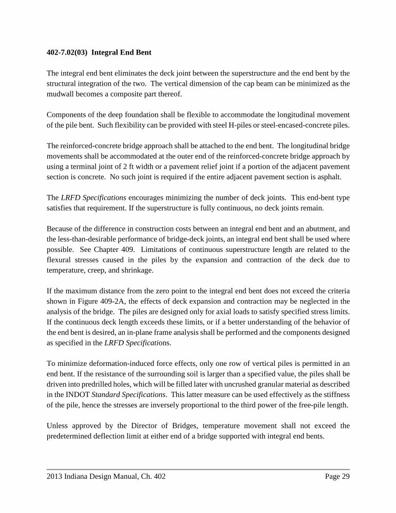
402-7.02(03) Integral End Bent The integral end bent eliminates the deck joint between the superstructure and the end bent by the structural integration of the two. The vertical dimension of the cap beam can be minimized as the mudwall becomes a composite part thereof. Components of the deep foundation shall be flexible to accommodate the longitudinal movement of the pile bent. Such flexibility can be provided with steel H-piles or steel-encased-concrete piles. The reinforced-concrete bridge approach shall be attached to the end bent. The longitudinal bridge movements shall be accommodated at the outer end of the reinforced-concrete bridge approach by using a terminal joint of 2 ft width or a pavement relief joint if a portion of the adjacent pavement section is concrete. No such joint is required if the entire adjacent pavement section is asphalt. The LRFD Specifications encourages minimizing the number of deck joints. This end-bent type satisfies that requirement. If the superstructure is fully continuous, no deck joints remain. Because of the difference in construction costs between an integral end bent and an abutment, and the less-than-desirable performance of bridge-deck joints, an integral end bent shall be used where possible. See Chapter 409. Limitations of continuous superstructure length are related to the flexural stresses caused in the piles by the expansion and contraction of the deck due to temperature, creep, and shrinkage. If the maximum distance from the zero point to the integral end bent does not exceed the criteria shown in Figure 409-2A, the effects of deck expansion and contraction may be neglected in the analysis of the bridge. The piles are designed only for axial loads to satisfy specified stress limits. If the continuous deck length exceeds these limits, or if a better understanding of the behavior of the end bent is desired, an in-plane frame analysis shall be performed and the components designed as specified in the LRFD Specifications. To minimize deformation-induced force effects, only one row of vertical piles is permitted in an end bent. If the resistance of the surrounding soil is larger than a specified value, the piles shall be driven into predrilled holes, which will be filled later with uncrushed granular material as described in the INDOT Standard Specifications. This latter measure can be used effectively as the stiffness of the pile, hence the stresses are inversely proportional to the third power of the free-pile length. Unless approved by the Director of Bridges, temperature movement shall not exceed the predetermined deflection limit at either end of a bridge supported with integral end bents.

Page 30 2013 Indiana Design Manual, Ch. 402
402-7.02(04) Non-Integral End Bent This consists of a semi-integral end bent or an end bent utilizing an expansion joint. This end bent type shall be used where an integral end bent is not feasible based on the criteria shown in Figure 409-2A. Further explanations of semi-integral-end-bent and expansion-end-bent usage are described in Chapter 409. 402-7.02(05) Abutment A concrete abutment may be supported with either a spread footing or a deep foundation. It consists of a vertical stem which supports the superstructure by means of bearings with or without pedestals, or a mudwall which retains the embankment fill in the longitudinal direction of the bridge. It can support the end of a reinforced-concrete bridge approach. Wingwalls are usually required to retain the fill in the transverse direction. Continuity of the riding surface between the abutment and the superstructure is provided by means of a deck joint. For restricted geometry, a tall superstructure, or large relative longitudinal movement between the superstructure and the substructure, the abutment may be the only feasible alternative. It is, however, expensive to construct. For a small bridge, its cost can be out of proportion with respect to other components of the bridge. With large abutments located close to the edge of roadway or waterway below, superstructure spans can be reduced. Large abutments, however, can result in poor aesthetics of the bridge, and can impair visibility at an overpass. An abutment is affected by the bridge geometry and site conditions. Therefore, it can be designed in an infinite variety of shapes and sizes. Figure 402-7B indicates the parts of a typical cantilever abutment of rectangular layout supported with a spread footing. If the wingwalls are large, they can be directly supported with spread footings or footings with piles. 402-7.03 Pier or Frame Bent The above-ground portion of a substructure can be categorized as illustrated in Figures 402-7C and 402-7D. These are discussed below. See Section 409 for more information on interior supports. 402-7.03(01) Pier A pier is made of reinforced concrete. Where piers are directly exposed to public view, their appearance may be improved as discussed in Section 402-5.07.

2013 Indiana Design Manual, Ch. 402 Page 31
The round column shown in Figure 402-7C detail (a) is the most economical, because it is structurally efficient and easy to construct. The single, narrow wall shown in Figure 402-7C detail (d) is most suitable if its structural height is relatively small and the superstructure is a concrete slab; if the superstructure is made of longitudinally placed, precast concrete components; or if it includes closely spaced, longitudinal beams. For a greater structural height, a hammerhead pier, as shown in Figure 402-7D detail (b), either with a rectangular or rounded stem, is more suitable. The use of twin walls shown in Figure 402-7C detail (e) permits the segmental construction of a medium-span superstructure made from longitudinal precast concrete components without falsework. A larger pier located in a waterway susceptible to ice accumulation may be fitted with a sharp icebreaker nose as shown in Figure 402-7C detail (f). A medium- or large-span, single-box superstructure may be supported by means of aesthetically-pleasing flared piers, as illustrated in Figure 402-7D detail (c). In a debris-prone stream, the wall-type pier is preferred. 402-7.03(02) Frame Bent A frame bent, as shown in Figure 402-7E can be constructed from steel, concrete, or a combination of these materials. Steel is used only for a temporary structure due to of problems associated with corrosion, the environmental impact of repainting, vulnerability to collision, and the difficulty in providing an appropriate pier head. Steel is not the most competitive material for resisting force effects which are primarily compressive. A concrete frame bent shall instead be used to support steel or concrete structural members. The columns of the bent can be either circular or rectangular in cross section. Circular columns are usually more economical. The columns shall be directly supported by the slab portion of a spread footing or by the pile cap. Figure 402-7E detail (a) illustrates the most common type of concrete bent consisting of vertical columns and a cap beam, used in an overpass structure. Figure 402-7E detail (b) depicts a tall concrete bent which can be used in a cable-stayed bridge. Concrete can provide an economical and visually attractive substructure. 402-8.0 SUPERSTRUCTURE This Section discusses the considerations in the selection of the superstructure type.

Page 32 2013 Indiana Design Manual, Ch. 402
402-8.01 General The State’s geography is relatively flat with predominately small waterways, therefore, the largest of the available bridge types is rarely appropriate. The bridge types provided in Figure 402-8A are those which are either traditional or which may have an application resulting from the introduction of the AASHTO LRFD Specifications. A minimum of four beam lines is required for a multi-beam application on a State route. The minimum deck thickness is 8 in., including a 1/2-in. sacrificial wearing surface. The following provides guidance in selecting the bridge-superstructure type that is most appropriate for the highway geometry, span lengths, and site conditions. 1. Span Lengths. Figure 402-8B indicates the typical ranges of span lengths for which each
superstructure type will apply. 2. Superstructure Depth. See LRFD Table 2.5.2.6.3-1 for the traditional minimum depth for
constant-depth superstructure for each structure type. 3. Superstructure Characteristics: Figure 402-8C tabulates basic characteristics of the
superstructure types shown in Figure 402-5A. 402-8.02 Superstructure Type 402-8.02(01) Type A: Reinforced Cast-in-Place Concrete Slab The reinforced cast-in-place concrete slab is used because of its suitability for short spans and its insensitivity to skewed or curved alignments. It is the simplest among all superstructure systems, as it is easy to construct. Structural continuity can be achieved without difficulty. Haunching is used to decrease maximum positive moments in a continuous structure by means of attracting increased negative moments to the haunches and providing adequate resistance at the haunches for the increased negative moments. It is a simple, effective, and economical way to maximize the resistance of a thin concrete slab. As illustrated in Figure 402-8D, there are three ways of forming the haunch. The parabolic shape (a) is the most natural in terms of stress flow, and the most aesthetic. It is preferred where the elevation is frequently in view. The parabolic haunch, however, is difficult to form and, as alternatives, the straight haunch (b) and the drop panel (c) shall be considered where appropriate. The narrow pile cap (d), used in conjunction with an extended-pile substructure, does not qualify as an effective haunch.

2013 Indiana Design Manual, Ch. 402 Page 33
Figure 402-8E depicts the elevation of a three-span, continuous-haunched slab bridge. The preferable ratio between interior span and end spans is approximately 1.25 to 1.33 for economy, but the system permits considerable freedom in selecting span ratio. The ratio between the depths at the centerlines of interior piers and at the point of maximum positive moment shall be between 2.0 and 2.5. Except for aesthetics, the length of the haunch shall not exceed the kL values indicated in Figure 402-8D, where L is the end span length. Longer haunches may be unnecessarily expensive or structurally counterproductive. 402-8.02(02) Type B: Longitudinally Post-Tensioned, Cast-in-Place Concrete Slab The distinction between the type A and type B superstructures is the difference in how they are reinforced. Therefore, most of the information described above for type A is applicable. A shallow post-tensioned slab can be a feasible structural system for a given situation. Structural analysis shows that if the haunch ratio is about 2.5, the ratio between maximum negative and positive moments is also approximately 2.5. This indicates that the amount of post-tensioning steel, as determined for positive moment, will be consistent with the requirements for negative moment, producing a balanced design. As an alternative, the right-hand side of the elevation in Figure 402-8F is shown with a constant-depth soffit. The constant-depth soffit does not produce a balanced design; therefore additional negative-moment reinforcement is required. This results in a reduction in span range and increases the probability of spalling by providing a large amount of reinforcing steel close to the surface. By increasing the span-to-depth ratio to a maximum of 1:30 for simple spans and 1:40 for continuous spans, cost savings can be obtained in both superstructure and substructure. The use of the potentially-extreme ratio shall be made with consideration, as appropriate, for deflection performance and dynamic response. There are two alternatives for transverse steel. One is with normal reinforcement, for which the requirements are the same as for a type A deck system. The second alternative is shown in Figure 402-8G which incorporates transverse post-tensioning. The cross section can be with or without cantilever overhangs. In the latter situation, two levels of post-tensioning instead of one can be used. As illustrated in Figure 402-8F, transverse tendons shall be fanned in the end zones of a skewed bridge. If the bridge railing is attached to a cantilever overhang at isolated points such as posts, both longitudinal and transverse reinforcement shall be provided therein. The problem that often rises with transverse post-tensioning on a deck of width of less than approximately 30 ft is the control of excessive seating losses, which makes the reinforced alternative preferable.

Page 34 2013 Indiana Design Manual, Ch. 402
402-8.02(03) Type C: Longitudinally Post-Tensioned, Cast-in-Place Concrete Box Girders This is a variation of type B, in which the deck system is considerably lighter and, therefore, more economical due to large, rectangular, and rhombic voids. This creates a multicell box-type superstructure, as illustrated in Figure 402-8H. This is often referred to as the California-type box girder. To facilitate the forming of a thin-walled box, the majority of these structures have a straight soffit. Consequently, considering longitudinal post-tensioning, this system is also unbalanced, requiring additional negative-moment steel. Full diaphragms are required at all interior piers and abutments. The preferred substructure type is the flared, rounded pier, which provides direct support for the two internal webs and provides the potential for a solid transverse moment connection, if required for seismic force effects. For type A, B, or D, concrete is placed to full depth in a single operation. For type C, it is poured in three stages. First, the bottom slab is placed with dowels for connecting the web reinforcement as shown in Figure 402-8H. Next, the web steel is assembled, to which the rigid tendon ducts are attached, and then the web concrete is placed between removable forms. The last step is to construct a form for the top slab, assemble its reinforcement, and pour the concrete. Thus, a large structure can be built without the need for expensive machinery, if it is close to firm ground. The system is suitable for an alignment with moderate curvature and skew. The structure is analyzed with the piers as a framed spine beam to obtain moment, shear, and torsion. For the latter, this system offers excellent resistance. 402-8.02(04) Type D: Two-Way Post-Tensioned, Cast-in-Place Concrete Spine-Beam with Cantilevers Type D is most suitable for an excessively curved or skewed alignment, and is insensitive to the location of its piers. The cross section is a variation of type B in which the application of large, cantilever overhangs reduces the weight of the superstructure. Above a certain structural depth, it becomes economical to further reduce the structure weight with round voids which are formed by means of stay-in-place steel pipes. The voided deck has a tendency to crack at the top near the centerline of the voids. To prevent the formation of cracks in the bridge, the top is transverse post-tensioned. This transverse post-tensioning lends itself to the formation of large cantilever overhangs and, thus, a dual use. This improved version, with or without voids, is illustrated in Figure 402-8 I.

2013 Indiana Design Manual, Ch. 402 Page 35
Considering span range, the type D system is a transition between the type B solid slab and type C cellular deck. Its cross section is not as effective as that of the cellular deck, but because its whole depth can be placed in one operation, it is less labor-intensive. The largest void used is approximately 4 ft diameter, providing for a structural depth of approximately 5 ft. A narrow bridge, as illustrated in Figure 402-8 I, requires a minimum of two voids. As the core widens or the structural depth decreases, the voids will be more numerous but of lesser diameter. If the core-void ratio, with the area of the wings excluded, does not exceed approximately 30%, a solid cross section, as shown in Figure 402-8 I, shall be used. To be economical, the void ratio shall be approximately 35%. If the ratio exceeds 40%, the LRFD Specifications considers the deck as a cellular, or box, construction. For the piers, slender, round columns may be used. For a short bridge such as an overpass, the columns may be framed into the superstructure. For a longer bridge, sliding bearings shall be applied. A long structure with flat horizontal curvature requires intermittently-located wide piers with two bearings to provide torsional stability. A sharply-curved structure has a high degree of inherent stability, therefore, stabilizing by means of two bearings or a line support, is required only at the abutments. 402-8.02(05) Type E: Prestressed, Precast Concrete Beams Precast, prestressed concrete I-beams were initially adopted as AASHTO types II, III, and IV. Later, types I, V, and VI were added to extend their span range at both the lower and upper ends of the spectrum. Currently, the AASHTO I-beam types I, II, III, and IV are used, along with the bulb-tee beams for longer spans. Prestressed, precast concrete box beams are also acceptable for a shallow construction depth. However, they shall not be placed either partially or entirely below the Q100 elevation. Figure 402-8J illustrates a typical superstructure cross section with prestressed, precast concrete I-beams. For a preliminary selection of an I-beam size and spacing, see Figure 402-8K, Prestressed Concrete I-Beam Selection Chart. The slab overhang shall be as wide as possible but shall be in accordance with the overhang criteria provided in Chapter 404. For a wide beam spacing, if foundation conditions permit, the beams can be individually supported by means of drilled shafts, as shown in Figure 402-7A detail (c), instead of a continuous pier cap.

Page 36 2013 Indiana Design Manual, Ch. 402
Figure 402-8L illustrates three variations of prestressed, precast concrete box beams. Alternative (a) is an open-box cross section. Its advantage over a closed box is in the forming of the beam. Alternative (b) is a closed, or spread, box, with a constant depth, cast-in-place deck. Alternative (c) is a keyed-in design. For transverse continuity of the deck, it shall have the top reinforcement shown, but not dedicated shear connectors. All three alternatives can have beam spacings of up to approximately 15 ft. Precast beams shall be continuous in the longitudinal direction for transient loads. In this arrangement, the beams retain their individual bearings, but their ends are incorporated in a common diaphragm which is cast monolithically with the deck. The reinforcement for flexural continuity is located in the deck. The strands are extended into the diaphragm to prevent separation at the bottom that can occur as a result of the upward bowing of the prestressed beam due to creep. The tendency for creep can be minimized by permitting the beam concrete to mature prior to placing the deck. The extended strands also increase the shear resistance of the prestressed beams. This system is adaptable without regard to skew. Horizontal curvature cannot easily be matched with a continuous structure, but only by means of a series of chorded spans laid out in a segmental form. 402-8.02(06) Type F: Bulb-Tee Beams Made Continuous by Means of Post-Tensioning Precast beams can be made continuous for both permanent and transient gravity loads by means of the application of longitudinal post-tensioning. However, the scheme is provided herein in conjunction with the bulb-tee because it appears to offer the best structural efficiency for this type of construction with reference to its large bottom flange required to resist high negative moments in compression. This efficiency is achieved by means of a certain level of sophistication in construction technology which is within current practice, but not uniformly practiced nationwide. Figure 402-8M illustrates the cross section of the Indiana bulb-tee beam. In addition to making the beam structurally effective, the wide top flange provides lateral stability, reduces the deck area to be formed, and furnishes a safe and comfortable walkway for the construction crew. The limits of practical hauling shall be considered from the plant to the work site in selecting span length and beam type and size. Fabricators shall be contacted early in project development for information regarding the feasibility of hauling to a specific site.

2013 Indiana Design Manual, Ch. 402 Page 37
The trajectory of the tendons follows that shown in Figure 402-8N. The draped tendons shall be as close as practical to the outer fibers of the beam, as the structural effectiveness of a tendon is directly proportional to the vertical distance between its highest and lowest points. If the sidespan is identical with the internal one and if the end is butted by another structure, the tendon anchorages may be located in the top of the beam. This increases tendon efficiency to avoid congestion. See Figure 402-8N. In either situation, an end-block at the anchorage end of the end beam will be required. One structure shall not include more than four continuous spans. Figure 402-8 O illustrates an intricate but convenient system of relatively large spans built from transportable, precast bulb-tee elements. The span element is the same as discussed above. The pier element is also the bulb-tee cross section but with a haunched soffit for improved negative-moment effectiveness. To avoid temporary falsework, thin-walled twin piers, as shown in Figure 402-7C detail (e) may be used. For temporary stability, each set of pier elements shall be joined together with four diaphragms and the deck. The span elements and the deck above them shall be constructed with two-stage post-tensioning. Both systems accept unlimited skew but no curvature. 402-8.02(07) Type G: Deck System with Prestressed, Precast Longitudinal Elements Prestressed, precast concrete longitudinal members of various cross sections have been used to create a bridge deck. The performance of these deck systems has not always been desirable due to the disintegration of longitudinal shear keys between the members. The keys, unprotected by transverse pressure, become vulnerable due to shortening and warping of the prestressed members, and they fail to transfer live-load shear. This results in potential overloading of the members and in an irresolvable maintenance problem for the deck. The beneficial effect of keeping the keys under transverse pressure had been recognized previously, and third-point transverse post-tensioning had been introduced as an option. Unfortunately, the combination of low prestress, the unmatched side surfaces of the members, and the quality of the keys, has rendered this improvement ineffective. The grout in the key is impossible to inspect due to the way the key is formed. LRFD Specifications Article 5.14.4.3 requires a keyway joint of not less than 7 in. depth between the members. In lieu of the traditional key, the LRFD Specifications prefers a V-shaped joint which is easy to fill and convenient to inspect. The post-tensioning ducts shall be located at the mid-depth of the joint, and not at the mid-depth of the beam. The minimum transverse prestress across the joint is 250 psi, or 20 kip/ft of length, which is a force nearly twice the traditional value. If the deck is not transversely post-tensioned, it requires a structural overlay depth of not less than 4.5 in.

Page 38 2013 Indiana Design Manual, Ch. 402
The current practice is as follows. 1. Precast members have a composite structural-concrete overlay with a minimum depth of 5
in. 2. Precast members are transversely post-tensioned whether or not a structural overlay is used. 3. A traditional trapezoidal key is used instead of a V-shaped key. 4. The wet-joint depth between elements is 8 in. As illustrated in Figure 402-8P, there are four precast, prestressed concrete members which can be economically assembled into a simply-supported deck system. In descending order of span length, these are the single tee, the double tee, the box, and the solid slab. The LRFD Specifications also includes channel sections, but these will herein be considered as a double tee with truncated cantilever overhangs. The precast members either serve as the finished roadway or provide an uninterrupted formwork for a structural-concrete overlay. The sections’ depth of the top flange, d, shall not be less than 6.5 in. if post-tensioned, and not less than 4 in. if overlaid. If the member is transported by truck, its width shall not exceed 8 ft. There is an incentive to decrease the number of joints in the deck, but this results in larger members. The transportability and erectability of the members shall be investigated considering both weight and geometry, early in project development, with potential contractors. Although the double tee has a less than perfect cross section considering structural efficiency, this is offset due to ease of forming. For simplicity, only the box alternative is shown for the two methods of assembly as outlined above. Figure 402-8Q is applicable to all four sections. For a box or slab section, end diaphragms are not required. For a single- or double-tee section, end diaphragms are required. Since it is nearly impossible to manufacture perfectly matched precast members, the surface of the grouted and post-tensioned deck shall be ground, where necessary. For this, the minimum specified depth of the top flange shall be increased by 0.5 in. No variation of this system is applicable to a curved alignment. Skew is possible, but forming and casting the ends of each member with an angle of other than 90 deg will cause difficulty in manufacturing. The desirable limit for skew is 30 deg. A skew angle of greater than 45 deg not permitted. This system can also be made continuous in the longitudinal direction by using a monolithic diaphragm and continuity steel or longitudinal post-tensioning similar to precast-concrete beams discussed above. A double tee, however, which lacks an effective bottom flange, requires other measures to improve the compressive strength of the stems at the point of junction.

2013 Indiana Design Manual, Ch. 402 Page 39
402-8.02(08) Type H: Segmental Concrete Box The use of a segmental concrete structure may be considered for the following: 1. a bridge with long spans; 2. a long bridge with medium-length spans and limited vertical and horizontal curvature
designed with essentially identical precast segments; or 3. a sharply-curved bridge where cast-in-place operations are not permitted. The metal formwork, especially built for each construction, is expensive, and one of the above considerations shall be used to justify the use of this structure type. Figure 402-8R illustrates a typical cross section with a single cell. This type of superstructure has its own technical literature with reference to long spans. A summary appears in the AASHTO Guide Specifications for Design and Construction of Segmental Concrete Bridges. The segments can be assembled by means of either span-by-span or balanced-cantilever methods, using either precast or cast-in-place concrete segments. The preferred method of longitudinal post-tensioning is by means of internal bonded tendons. However, longitudinal post-tensioning with unbonded tendons is also permitted. These are threaded through deviation blocks and anchored in the diaphragms of the adjacent spans. To avoid longitudinal cracking, the top slab shall be transversely post-tensioned. The segmental interfaces shall be match-cast and shall include shear keys, which shall be bonded with epoxy adhesive. 402-8.02(09) Type I: Composite Steel Rolled Beam Low structural depth, thick webs, and wide flanges characterize most of the steel beams rolled today. Therefore, most of these beams are considered compact sections that do not require intermediate web stiffeners and require minimum lateral support. They are not economical based only on least steel weight. Instead, economy is derived from low fabrication costs and minimal or sometimes nonexistent wind or sway bracing. Spacing of diaphragms shall be in accordance with Chapter 407. The depth-to-span ratio for the beam plus slab shall not exceed 1:24 for simple spans or 1:33 for continuous spans. For continuous spans, the span is the distance between points of dead-load contraflexure.

Page 40 2013 Indiana Design Manual, Ch. 402
Cover plates for rolled beams are prohibited on the flanges. Weathering, or unpainted, steel shall be used to lower the future maintenance cost. See Chapter 407 for steel-weight curves, which can be used to provide a preliminary estimate of steel weight. With proper diaphragms, this structure type is suitable for a skewed or horizontally-curved alignment. See Chapter 407 for more information. See Figure 402-8 S for a typical steel rolled beam section. 402-8.02(10) Type J: Composite Steel Plate Girder Steel plate girders may be used in lieu of steel rolled beams for spans that are uneconomical, or not feasible, for that type of structure. The depth-to-span ratio for the girder plus slab shall not exceed 1:20 for simple spans or 1:28 for continuous spans. For continuous spans, the span is the distance between points of dead-load contraflexure. Weathering, or unpainted, steel shall be used to lower the future maintenance cost. See Chapter 407 for steel-weight curves, which can be used to provide a preliminary estimate of steel weight. It is seldom economical to use the thinnest web plate permitted by LRFD. The use of a thicker web and few or no intermediate transverse or longitudinal stiffeners shall be investigated. For appearance, transverse stiffeners shall be located on the inside of the outside girders. With proper diaphragms, this structure type is suitable for a skewed or horizontally-curved alignment. See Chapter 407 for more information. See Figure 402-8T for a typical composite steel plate girder section. 402-8.02(11) Type K: Composite Open Steel Box Girder Single steel box girders, usually closed on the top due to an orthotropic steel deck, are used for large spans which are rarely required. As illustrated in Figure 402-8U, the lack of fatigue-prone sway and wind-bracing connections make the open steel box less susceptible to fatigue damage, and the use of two girders as a minimum is permitted. This system is adaptable to a curved alignment and where the available structural depth is limited. Moderate skew causes no problems. During transportation and construction, the open box can require sway and internal, or wind, bracings. The mechanically-connected sway bracings shall be removed after construction. If too much torsional rigidity is provided to the boxes, they can cause longitudinal cracking in the slab, especially if the slab had been empirically designed. A minimum of two bearings per girder shall

2013 Indiana Design Manual, Ch. 402 Page 41
be used to provide adequate torsional resistance. A solid diaphragm with an access hole shall be placed at all bearing points. Transverse web stiffeners may be used, but the use of longitudinal web stiffeners shall be avoided. 402-8.02(12) Type L: Wood Superstructure The use of a wood superstructure is limited to a low-volume, local road, and is subject to the approval of the Director of Bridges. See Chapter 413. A wood bridge can be an attractive alternative for a small span or a temporary bridge. Wood can be used either as a deck and or can be directly supported by wood trestles, or piers. As illustrated in Figure 402-8V, there are two variations for use as a deck unsupported by other components. The deck may be constructed from wood panels, prefabricated either by gluing or spiking, which are of full-span length and are connected together by means of bolting spreader beams to the underside of the panels at intervals not exceeding 8 ft. The LRFD Specifications permits the use of this type of deck without spreader beams, but its use is not recommended. The deck shall have an asphaltic wearing surface. Because the use of this deck is limited to simply-supported spans, it is recommended for a rural or secondary road where a rectangular layout can easily be achieved. Alternatively, the deck can be constructed from prebored longitudinal laminates which are laid out in a staggered design and assembled by means of transverse post-tensioning. The laminates are held together by means of interface friction, and no other fasteners are required. To improve rideability and surface friction, the use of an asphaltic surface treatment is mandatory. The system lends itself to continuous construction with limited curvature, but with unlimited skew. Two other alternatives are also available for a transversely post-tensioned wood deck. One includes glued wood ribs, by which the flat deck is transformed into a series of tee-beams. The second is an extension of the first by the addition of a post-tensioned bottom flange by which a cellular cross section is created. Either flat deck can also be used as a transversely-positioned slab supported with longitudinal beams. The post-tensioning will run longitudinally in the laminated deck. As illustrated in Figure 402-8W, wood can be used also as a primary longitudinal component as either sawn or native, in closely-spaced stringers or widely-spaced glue-laminated beams. For composite construction, the concrete slab shall be keyed into the top of the wood component and

Page 42 2013 Indiana Design Manual, Ch. 402
secured with spikes. Both alternatives permit skew, but neither permits curved alignment or continuous construction. 402-8.02(13) Type M: Structure Under Fill This type of structure can be an attractive alternative for a small stream or ditch crossing, a minor highway or street crossing, or a pedestrian or animal crossing. This type of structure may be made of steel, aluminum, or concrete. The most common configurations used are the three-sided concrete or steel structure, four-sided precast concrete box structure, structural plate pipe arch, or circular pipe. The structure-sizing process is performed in accordance with a priority system. This system consists of six trials where specific installations are considered prior to evaluating other structure types, such as a reinforced cast-in-place concrete slab. The design priority system is as follows: Trial 1: single circular-pipe installation. Trial 2: single deformed-pipe installation. Trial 3: single specialty-structure installation. Trial 4: multiple circular-pipe installation. Trial 5: multiple deformed-pipe installation. Trial 6: multiple specialty-structure installation. The principles of the priority system are summarized below. 1. A pipe structure is preferred to a precast concrete box section, precast concrete three-sided
structure, or structural plate arch. 2. A circular pipe is preferred to a deformed pipe. 3. A single-cell installation is preferred to a multiple-cell installation. See Chapter 203 for more information on the culvert-sizing process. Additional considerations and design criteria for each type of buried-structure system are provided in LRFD Bridge Design Specifications, Section 12. If a specialty-structure installation is selected, manufacturers of such structures shall be contacted. See Section 203-2.05 for more information. 402-9.0 ALTERNATIVE DESIGN PROCESS

2013 Indiana Design Manual, Ch. 402 Page 43
For a bridge project with an estimated construction cost of over $10 million, the project manager and the designer shall investigate the possibility of performing a dual set of contract documents for two different structure types. The additional design fees for performing dual designs are minor in comparison to the results of a competitive contract letting. Designs for alternative structures shall be of equal safety, serviceability, and aesthetic value. Similarly, for foundations whose construction costs are expected to exceed $2 million, the project manager and the designer shall investigate the possibility of performing a dual set of foundation contract documents. 402.10 ACCELERATED CONSTRUCTION The concept of accelerated construction is increasing in popularity and frequency of use. If it is determined that a project can benefit from an accelerated-construction method, this shall be coordinated with the project manager. This type of construction shall be evaluated individually for each project, and shall not be considered for each structure size and type analysis.

Material Superstructure Type Typical Span
Length (ft)
Precast
Concrete 3-Sided Structure 12 – 48
Cast-in-Place
Concrete Continuous Reinforced Slab 20 – 45
Prestressed
Concrete
Box Beams, Depth 12 in. through 27 in. 30 – 60
Box Beams, Depth 27 in. through 42 in. 60 – 85
I-Beams, AASHTO Type I 35 – 50
I-Beams, AASHTO Type II 40 – 65
I-Beams, AASHTO Type III 55 – 85
* I-Beams, AASHTO Type IV 70 – 110
Bulb-T Beams, Top-Flange Width 48 in. or 60 in. 80 – 140
Bulb-T Beams, Top-Flange Width 49 in. or 61 in. 65 – 165
Post-Tensioned Bulb-T Beams 140 – 200
Post-Tensioned Slab 50 – 80
Structural
Steel
Steel Rolled Beams < 100
Steel Built-Up Plate Girders > 70
* These are generally used only in rehabilitating a structure. Bulb-T beams are preferred
for a new or replacement structure.
ECONOMICAL STRUCTURE-TYPE SELECTION
Figure 402-5A


Bent No. 1 Pier No. 2
Semi-Fixed
Typically set at 1’-0"
from Edge of Clear Zone
to front face of Retaining Wall
Bent No. 3
A
A
Figure 402-6B
NEW CONSTRUCTION / 4R PROJECT
BRIDGE UNDERPASS CROSS SECTION
20 H: 1 V 8:1
Span B
Span A
14’-0"
Min. cl.
Bottom of Beam
ZoneClear
Min. Vert. Clr. A Min. Vert. Clr. B
MSE Wall (typ.)
(typ.)
End Bent
Integral

Figure 402-6C
3R PROJECT
NEW BRIDGE UNDERPASS CROSS SECTION
Min. vertical clearance
Shoulder
Traveled Way
Shoulder
2:12:1
critical clearance point
Low structure at

ˆ
Figure 402-6D
TWO-LANE, TWO-WAY HIGHWAY
BRIDGE CROSS SECTION
2 %
Traveled Way
2 %
(See Fig. 402-6H)
offset or curb offset
Shoulder width plus railing
Clear Roadway Width
(See Fig. 402-6H)
offset or curb offset
Shoulder width plus railing
railing or curb
Inside face of
railing or curb
Inside face of

Traveled Way 1Median Traveled Way
2 % 2 % 2 % 2 %
Traveled Way Median Traveled Way
2 %2 %
DEPRESSED MEDIAN
FLUSH MEDIAN
(See Fig. 402-6H)
offset or curb offset
Shoulder width plus railing
Clear Roadway Width
ˆ ˆ
(See Fig. 402-6H)
offset or curb offset
Shoulder width plus railing
railing or curb
Inside face of
railing or curb
Inside race of
(See Fig. 402-6H)
offset or curb offset
Shoulder width plus railing
Clear Roadway Width
(See Fig. 402-6H)
offset or curb offset
Shoulder width plus railing
1
ˆ
Inside face of railing or curb Inside face of railing or curb
structure.
A raised island or CMB may be warranted. See Chapter 55 for criteria on median width for a single1
BRIDGE CROSS SECTION
DIVIDED HIGHWAY - SINGLE STRUCTURE
Figure 402-6E

BRIDGE CROSS SECTION
TWIN STRUCTURES - FOUR LANES
Figure 402-6F
Traveled Way Traveled Way
2 % 2 %2 %2 %
5’-8" 5’-8"
(See Fig. 402-6H)
railing offset
Shoulder width plus
(See Fig. 402-6H)
railing offset
Shoulder width plus
railing or curb
Inside face of railing or curb
Inside face of
railing or curb
Inside face of
ˆ ˆ
Clear Roadway Width Clear Roadway Width

2 %2 % 2 % 2 %
adjacent to the median. For four lanes in one direction, the crown will be in the center of the traveled way.
For three lanes in one direction, the crown will be between the middle travel lane and the travel lane NOTE:
(See Fig. 402-6H)
railing offset
Shoulder width plus
(See Fig. 402-6H)
railing offset
Shoulder plus (See Fig. 402-6H)
railing offset
Shoulder width plus
Clear Roadway Width
Traveled Way
Clear Roadway Width
Traveled Way
railing or curb
Inside face of
railing or curb
Inside face of railing or curb
Inside face of
Figure 402-6G
TWIN STRUCTURES - SIX OR MORE LANES
BRIDGE CROSS SECTION

at 6’-3" Spacing
W-Beam Guardrail
Guardrail Transition
Traveled Way
Edge of
Clear-Roadway Width
Edge of Bridge
Offset
Bridge Railing
Plus Bridge Railing Offset
Shoulder Width
Clear-Roadway Width
Edge of Bridge Plus Bridge Railing Offset
Shoulder Width
Offset
Bridge Railing
Traveled Way
Edge of
for Flare Rate
See Fig. 49-4F
at 6’-3" Spacing
W-Beam Guardrail
Guardrail Transition
Travel Lane
Offset Loss (or Gain)
Offset Loss (or Gain)
See 49-4.01(01)
Reduced Guardrail Offset
See 49-4.01(01)
Guardrail Offset
See 49-4.01(01)
Guardrail Offset
Traffic
Traffic
Railing Transition
Concrete Bridge
Railing Transition
Concrete Bridge
Travel Lane
(UNIFORM OFFSET)
PREFERRED
(TAPERED OFFSET)
ACCEPTABLE IN RESTRICTED CONDITION
Width Without Guardrail
Usable Roadway Shoulder
Width Without Guardrail
Usable Roadway Shoulder
(Page 1 of 2)
Figure 402-6H
GUARDRAIL TRANSITION TO BRIDGE RAILING
BRIDGE-RAILING OFFSET
details.
See Page 2 of 2 for Offset Gain/Loss NOTE:

Clear-Roadway Width
Edge of Bridge
Offset
Bridge RailingSee 49-4.01(01)
Guardrail Offset
Railing Transition
Concrete Bridge
Transition
Guardrail
Offset Gain
4"
BRIDGE RAILING TRANSITION TYPE TPF, TPS, OR TTX
or TX (not shown)
Railing Type PF, PS,
Concrete Bridge
Clear-Roadway Width
Edge of Bridge
Offset
Bridge Railing
See 49-4.01(01)
Guardrail Offset
Railing Transition
Concrete Bridge
Offset Loss
4"
Transition
Guardrail
BRIDGE RAILING TRANSITION TYPE TFC OR TFT
or FT
Railing Type FC
Concrete Bridge
Clear-Roadway Width
Edge of Bridge
Offset
Bridge Railing
See 49-4.01(01)
Guardrail Offset
Railing Transition
Concrete Bridge
Transition
Guardrail
Offset Loss
4"
or CF-1
Railing Type TF-2
Concrete Bridge
BRIDGE RAILING TRANSITION TYPE TTF-2
(Page 2 of 2)
Figure 402-6H
GUARDRAIL TRANSITION TO BRIDGE RAILING
BRIDGE-RAILING OFFSET
in Restricted Condition
Reduced Guardrail Offset
or
Guardrail Offset
Offset Loss (-)
or
Offset Gain (+)= +
Offset
Bridge Railing
Bridge Railing Offset = (2’-0") + (- 4") = 1’-8"
4" of Railing Offset is lost through the Bridge Railing Transition Type TFC.
Guardrail Offset of 2’-0" on the bridge approach, and Bridge Railing Type FC.Example:

Figure 402-6 I
FLAT OR SHORT HORIZONTAL CURVE
BRIDGE WIDTH
Tra
vele
d
Way
Clear Roadway Width
tangency
Point of
ˆ end bents
Long chord between
A
bridge railing offset
Shoulder width plus
and roadway for bridge railing
Intersection curve, end of slab
allowed if shown to be economical.
* Additional width in excess of 1’-0" is
See Chapter 55 for bridge width.NOTE:
ˆ End Bent ˆ End Bent
bridge railing offset
Shoulder width plus
A + 1’-0" *£

Type Minimum Vertical
Clearance (ft)
Railroad Under Roadway 23’-0” (1)
Roadway Under Pedestrian Bridge 17’-6” (2)
Freeway Under Roadway 16’-6” (2) (3)
Arterial Under Roadway 16’-6” (2) (4)
Collector Under Roadway 14’-6” (2)
Local Facility Under Roadway 14’-6” (2)
Non-Motorized-Vehicle-Use
Facility Under Bridge 10’-0” (5)
Notes:
(1) See Chapter 413 for additional information on railroad under roadway.
(2) Value allows 6 in. for future resurfacing.
(3) A 14’-6” clearance, which includes provision for future resurfacing, may be used
in an urban area where an alternative freeway facility with a 16’-0” clearance is
available.
(4) In a highly-urbanized area, a minimum clearance of 14’-6”, which includes
provision for future resurfacing, may be provided if there is at least one route
available with a 16’-0” clearance.
(5) Value allows for clearance of a maintenance or emergency vehicle.
VERTICAL CLEARANCE
Figure 402-6J

LOW SIDE
HIGH SIDE
LOW SIDEHIGH SIDE
Figure 402-6K
END-BENT BERM
2:1 max.
2:1 max.
Deck
Shoulder Line
Berm
6" min.
3’-0"
Deck
Shoulder Line
1’-8" max.
Berm
3’-0"
Deck
3"-0" Berm
1’-8" max.
6" min.

Tangent Section
Cro
wn for
MODIFIED SUPERELEVATION TRANSITION FOR TWO-LANE ROADWAY
ALTERNATIVE MODIFIED SUPERELEVATION TRANSITION FOR TWO-LANE ROADWAY
SuperelevationLimits of Full
Tangent Section
Cro
wn for Limits of Transition Limits of Transition
of pavement
Outside edge
of pavement
Inside edge
Profile
Out-to-Out Bridge DeckCro
wn for
Tangent Section
Cro
wn for
Tangent Section
V.C.
V.C.
V.C.
V.C.
V.C.
V.C.
V.C.
V.C.
SuperelevationLimits of Full
Limits of TransitionLimits of Transition
of pavement
Outside edge
V.C.
V.C.
V.C.
V.C. V.C.
V.C.
V.C.
V.C.
V.C.
V.C.
Bridge Deck
Out-to-Out
of pavement
Inside edge
Profile
NOT DESIRABLE
STANDARD SUPERELEVATION TRANSITION FOR TWO-LANE ROADWAY
Figure 402-6L
SUPERELEVATION TRANSITION DIAGRAM FOR BRIDGE
Cro
wn for
Tangent Section
Cro
wn for
Tangent Section
Limits of Transition
SuperelevationLimits of Full
Limits of Transition
V.C.
V.C.
V.C.
V.C.V.C.
V.C.
V.C.
V.C.
of pavement
Outside edge
Bridge Deck
Out-to-Out
of pavement
Inside edge
Profile

A
A
SECTION A-A
ˆ Bent ˆ Bent
ˆ Structure
ˆ Bent ˆ Bent
E W F
2
1
2
1A B
D
C
C
D
B A
El. A
El. B
El. AEl. B
Interior supports are not shown.
Waterway Area Required will be determined in the waterway opening analysis. NOTE:
El. C = Bottom of channel elevation
El. B = Elevation of top of slab
El. A = Elevation of top of slab
F = (2) (El. B - C - D - El. C)
E = (2) (El. A - C - D - El. C)
D = Distance from bottom of slab to berm elevation
C = Anticipated thickness of reinforced concrete slab
B = Width of berm
A = One half of the cap width
El. D100
Q
El. C
ˆ Channel Sta.
T
Required
Waterway Area
% Grade
Figure 402-6M
REINFORCED CONCRETE SLAB STRUCTURE
STRUCTURE LENGTH FOR STREAM CROSSING
W = Width of channel perpendicular to channel centerline
PERPENDICULAR TO CHANNEL
2 (El. D - El. C) 2 (El. D - El. C)
channel^Structure Length,
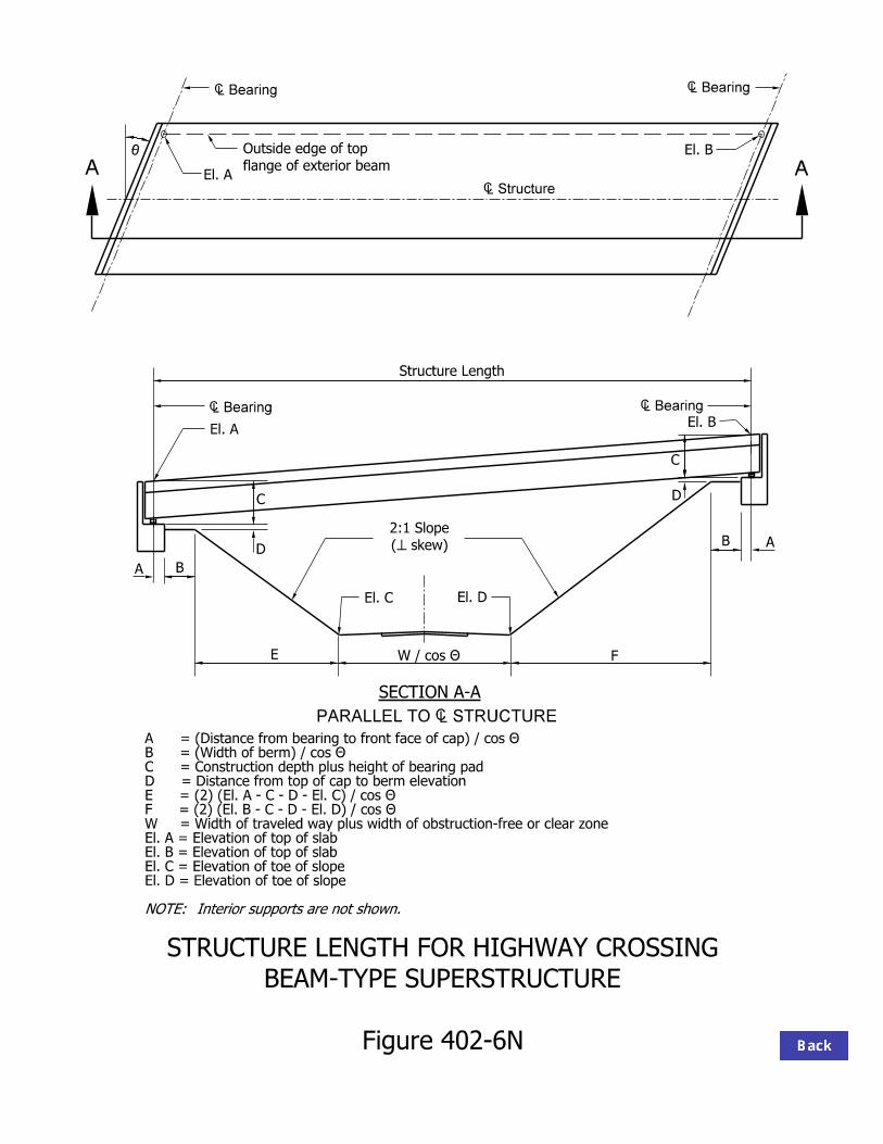
AA
SECTION A-A
ˆ Structure
ˆ Bearing ˆ Bearing
C = Construction depth plus height of bearing padD = Distance from top of cap to berm elevation
W = Width of traveled way plus width of obstruction-free or clear zoneEl. A = Elevation of top of slabEl. B = Elevation of top of slabEl. C = Elevation of toe of slopeEl. D = Elevation of toe of slope
Interior supports are not shown.NOTE:
Figure 402-6N
BEAM-TYPE SUPERSTRUCTURE
STRUCTURE LENGTH FOR HIGHWAY CROSSING
A = (Distance from bearing to front face of cap) / cos T B = (Width of berm) / cos T
E = (2) (El. A - C - D - El. C) / cos T F = (2) (El. B - C - D - El. D) / cos T
PARALLEL TO ˆ STRUCTURE
0
A B
C
D
E F
B A
D
C
El. B
El. A
El. A
El. C El. D
El. B
ˆ Bearing ˆ Bearing
flange of exterior beam
Outside edge of top
Structure Length
W / cos T
skew)(̂
2:1 Slope

Figure 402-6 O
FOR RAILROAD GRADE SEPARATION
TYPICAL HORIZONTAL AND VERTICAL CLEARANCES
15’-0"
25’-0"
23’-0" Min.
Track
epolS
1:2
Subgrade
Subballast
3
2
Face of Pier
epolS 1:2
MSE Wall
Face of
track.
23’-0" minimum vertical clearance measured 6’-0" from centerline of existing or future 2
justification to INDOT for approval in accordance with 23 CFR 646.212 and 646.214.
maintenance access roadway, or for drainage purposes, the railroad must provide
requests additional horizontal clearance for the accommodation of a planned future track,
FHWA limits their fiscal participation to horizontal clearance up to 20 ft. When a Railroad 1.
Provide 15’-0" between centerlines for future track(s).4.
A crashwall is required if horizontal clearance is less than 25 ft to face of pier or MSE wall.3
Horizontal dimensions are measured perpendicular to the track and may vary by Railroad.5.
25’-0"
15’-0"
NOTES:


Superstructure
Soffit
Footing
Piles
Soffit
Bearings Soffit
Figure 402-7A
BASIC BENT TYPES
WITH SPREAD FOOTING
PIER OR FRAME BENT SUPPORTED (a)
WITH DEEP FOUNDATIONS
PIER OR FRAME BENT SUPPORTED (b) EXTENDED PILE BENT(c)
Connection
Framed
Bearing or Pier or Bent
Ground
Connection
Framed
Bearing or
Superstructure Superstructure
Pier or Bent
Ground
Pile Cap Footing
Drilled Shafts
drilled shafts
Cap Beam for
With or Without
Ground
Drilled Shafts
Piles or

Figure 402-7B
CANTILEVER ABUTMENT
Deck JointDeck Slab
Beam
MudwallBearing
Stem
Footing
Bridge Approach
Reinforced Concrete

ˆ Pier
ˆ Brid
ge
Angle
Skew
(a) ROUND COLUMN (b) RECTANGULAR STEM (c) ROUNDED STEM
(d) SINGLE WALL (e) TWIN WALLS (f) STEM WITH ICEBREAKER NOSE
Figure 402-7C
PIER STEM AND COLUMN CONFIGURATIONS PLAN VIEWS

Figure 402-7D
STEM TYPES FOR PIERS
(a) SINGLE WALL PIER (b) HAMMERHEAD PIER (c) FLARED PIER
structure
Super-
Single-Box

Figure 402-7E
FRAME BENTS
Cap Beam
Rectangular
Column
Ground
or Pile Cap
Spread Footing
Bent
Deck
Ground
(a) LOW CONCRETE BENT (b) TALL CONCRETE BENT
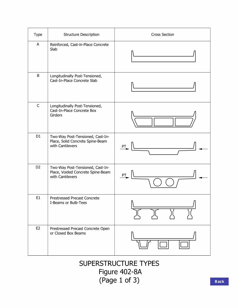
(Page 1 of 3)
Figure 402-8A
SUPERSTRUCTURE TYPES
Type Structure Description Cross Section
A
B
C
D1
D2
E1
E2
Slab
Reinforced, Cast-in-Place Concrete
Cast-In-Place Concrete Slab
Longitudinally Post-Tensioned,
Girders
Cast-In-Place Concrete Box
Longitudinally Post-Tensioned,
with Cantilevers
Place, Solid Concrete Spine-Beam
Two-Way Post-Tensioned, Cast-In-
with Cantilevers
Place, Voided Concrete Spine-Beam
Two-Way Post-Tensioned, Cast-In-
or Closed Box Beams
Prestressed Precast Concrete Open
PT
PT
I-Beams or Bulb-Tees
Prestressed Precast Concrete

(Page 2 of 3)
Figure 402-8A
SUPERSTRUCTURE TYPES
I
H
G4
G3
G2
G1
F
Type Structure Description Cross Section
Beams
Post-Tensioned Concrete Bulb-Tee
Longitudinal Concrete Single Tees
Jointed, Prestressed, Precast
Longitudinal Concrete Double Tees
Jointed, Prestressed, Precast
Longitudinal Concrete Boxes
Jointed, Prestressed, Precast
Longitudinal Concrete Slabs
Jointed, Prestressed, Precast
Segmental Concrete Box Girders
Composite Steel Rolled Beams
PT
PT
PT
PT
PT

Structure DescriptionType
J
K
L1
L2
L3
L4
M
Cross Section
Composite Steel Plate Girders
Composite Steel Boxes
Beams
Wood Panel Decks with Spreader
Composite Native Wood Stringers
Glulam Beams
Structure Under Fill
Stressed Wood DecksPlain Ribbed Boxed
Box Structure
Four-Sided
Structure
Three-Sided Pipe
PT
(Page 3 of 3)
Figure 402-8A
SUPERSTRUCTURE TYPES

Range (ft)
Type Structure Description Subgroup
< 30 30 ≤ L < 100
100 ≤ L < 150
150 ≤ L < 300
≥ 300
Straight X A Reinforced, Cast-in-Place
Concrete Slab Haunched X
Straight X X B Longitudinally Post-Tensioned,
Cast-in-Place Concrete Slab Haunched X X
C Longitudinally Post-Tensioned, Cast-in-Place Concrete Box Girder n/a X X
1. Solid X D
Two-Way Post-Tensioned, Cast-in-Place Concrete Spine-Beams with Cantilevers 2. Voided X X
1. I-Beams X 2. Bulb-Tee
Beams X E Prestressed, Precast Concrete Beams
3. Boxes X
Straight X F Post-Tensioned, Bulb-Tee Beams
Haunched X
1. Single Tees X 2. Double
Tees X
3. Boxes X G Jointed Prestressed Precast
Longitudinal Concrete Elements
4. Solid Slabs X
H Segmental Concrete Box Girders n/a X X X
I Composite Steel Rolled Beams n/a X X
J Composite Steel Plate Girders n/a X X X
K Composite Steel Box Girders n/a X X X X
1. Panel Deck X X 2. Stressed
Deck X
3. Stringers X L Wood Structure
4. Glulam Beams X
M Structure Under Fill n/a X
SPAN LENGTHS
Figure 402-8B

Type Structure Description Subgroup For
Skew
For Horiz. Curve
Aes- thetics
False- work
Speed of Construction
Maintenance Widening
Straight Good Good OK Yes Slow Good OK A
Reinforced, cast-in-place concrete slab Haunched Good Good Good Yes Slow Good OK
Straight Good Good OK Yes Slow Good OK B
Longitudinally post-tensioned cast-in-place concrete slab Haunched Good Good Good Yes Slow Good OK
C Longitudinally post-tensioned cast-in-place concrete box girders
N/A OK OK Good Yes Slow Good No
1. Solid Good Good Good Yes Slow Good No D
2-way post-tensioned, cast-in-place concrete spine-bms. with cantilevers 2. Voided Good Good Good Yes Slow Good No
1. I-Bms, Bulb-Ts OK Poor OK No OK Good OK E
Prestressed precast concrete beams 2. Boxes OK Poor OK No OK Good OK
Straight OK No OK No OK Good OK F Post-tensioned bulb-tee beams
Haunched OK No Good No OK Good OK 1. Single tees OK Poor OK No Good Good Good 2. Double tees OK Poor OK No Good Good Good 3. Boxes OK Poor OK No Good Good Good
G Jointed prestressed precast longitudinal concrete elements
4. Solid slab OK Poor OK No Good Good Good H Segmental concrete box girders N/A No OK OK Yes/No Good Good No I Composite steel rolled beams N/A OK OK OK No OK Expensive* OK J Composite steel plate girders N/A OK Good OK No OK Expensive* OK K Composite steel box girders N/A OK Good Good No OK Expensive* OK
1. Panel deck Good No OK No Good OK Good 2. Stressed deck Good Poor OK No Good OK Good 3. Stringers Good No OK No Good OK OK
L Wood structure
4. Glulam beams Good No OK No Good OK OK M Structure under fill N/A OK Good OK No Good Good Good
* Expensive if painted. Good if unpainted.
SUPERSTRUCTURE CHARACTERISTICS Figure 402-8C

ELEVATION
End Span, L Interior Span End Span, L
t
ˆ
Steel
Negative-Moment
Steel
Minimum Top
2.0 t to 2.5 t
Steel
Positive-Moment Steel
Minimum Bottom
Extended Pile Bent
Frame Bent or
Wall or
Figure 402-8D
TYPE A, REINFORCED CONCRETE SLAB SUPERSTRUCTURE

(c) DROP PANEL
(b) STRAIGHT(a) PARABOLIC
(d) CAP BEAM *
~ 0.30 L ~ 0.25 L
~ 0.20 L
as a structural haunch.
This configuration should not be used *
Figure 402-8E
TYPE A, HAUNCH CONFIGURATIONS FOR REINFORCED CONCRETE SLAB BRIDGE

ˆ DECK SYSTEM
Figure 402-8F
TYPE B, ALTERNATIVES FOR TRANSVERSE POST-TENSIONING

PLAN
ELEVATION
ˆ Pier
ˆ Bridge ˆ Pier
ˆ
not shown for clarity
Anchorage steel cage reinforcement
Additional
Tendons
Draped
for ducts (typ.)
Steel support
Tendons
Transverse
RECTANGULAR, SKEWED, OR CURVED LAYOUT
Figure 402-8G
TYPE B, POST-TENSIONED CONCRETE SLAB

Web Steel
Minimum Steel
Flared Rounded Pier
ˆ DECK SYSTEM
design
as required by
Slab reinforcement
Tendons
Draped
abutments
at piers and
Full diaphragm
Joints
Cold
Figure 402-8H
TYPE C, CALIFORNIA-TYPE BOX GIRDER

Transverse Post-Tensioning
clarity
not shown for
reinforcement is
Cantilever
Tendons
Draped
Former
Void
Steel
ˆ Deck System
Core Width
TYPE D1 TYPE D2
Figure 402-8 I
CONCRETE SPINE-BEAM WITH CANTILEVER
TYPE D, TWO-WAY POST-TENSIONED CAST-IN-PLACE

I Beam
Precast AASHTO
Beam
Bulb-Tee
Indiana
ˆ Deck System
ˆ Beam ˆ Beam ˆ Beam ˆ Beam
Deck
Cast-in-Place
Figure 402-8J
TYPE E1, COMPOSITE DECK WITH PRESTRESSED, PRECAST CONCRETE BEAMS

ILL 4
AASHTO I
AASHTO II
AASHTO III
AASHTO IV
GIR
DE
R S
PA
CIN
G (fe
et)
SIMPLE SPAN (feet)
BT 4.5
BT 5
BT 5.5 BT 6 BT 6.5
BT 7
fc’=6000 psi
30
4
5
6
7
8
9
10
11
12
40 50 60 70 80 90 100 110 120 130 140
Figure 402-8K
PRESTRESSED CONCRETE I-BEAM SELECTION CHART
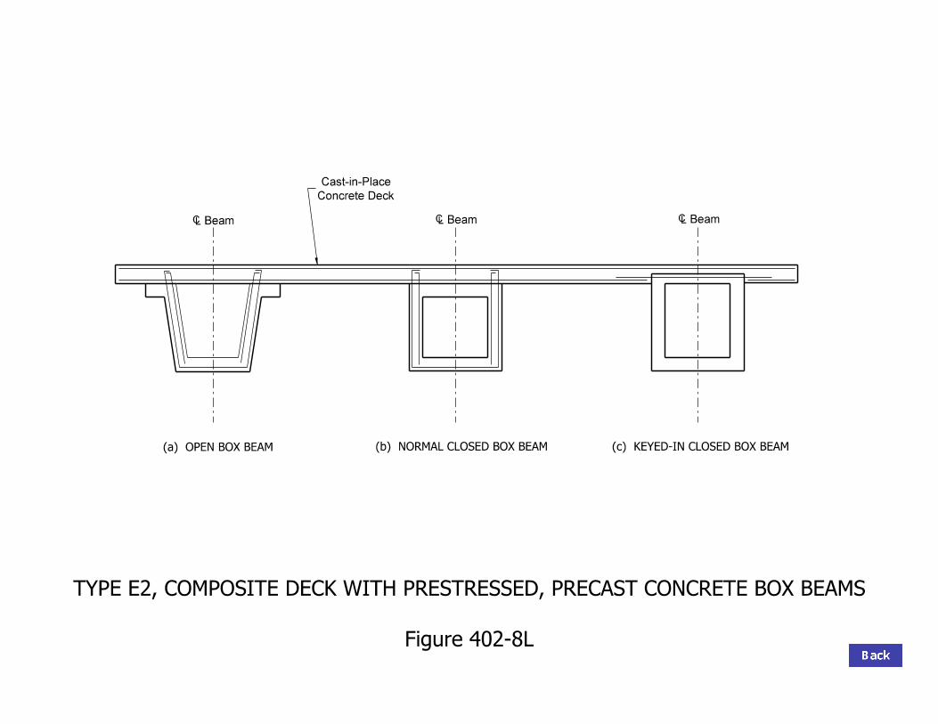
(a) OPEN BOX BEAM
ˆ Beam ˆ Beam ˆ Beam
Concrete Deck
Cast-in-Place
(b) NORMAL CLOSED BOX BEAM (c) KEYED-IN CLOSED BOX BEAM
Figure 402-8L
TYPE E2, COMPOSITE DECK WITH PRESTRESSED, PRECAST CONCRETE BOX BEAMS

Strands
Prestressing
Varies 4’-0" or 5’-0"
position, draped
ducts in upper
Post-tensioning
position
ducts in lower
Post-tensioning
Prestressing Strands
2’-1"
Figure 402-8M
TYPE F, INDIANA BULB-TEE BEAM

ˆ Bearing
Pockets
Top of Beam
Tendons
Beam
Block
End
Post-Tensioning
Stage Two
Post-Tensioning
Stage One
Figure 402-8N
POST-TENSIONING
TYPE F, TOP ANCHORAGE FOR LONGITUDINAL

with Diaphragm
Field Joint
Twin Wall Pier
Span Element
150’ Max.
Approx.
Pier Element
100’ Max.
Approx.
Approx. 250’ Max. Approx. 200’ Max.
Figure 402-8 O
CONSTRUCTED FROM LONGITUDINAL PRECAST-CONCRETE BEAM ELEMENTS
TYPE F, LARGE-SPAN BRIDGE

SINGLE TEE DOUBLE TEE BOX SOLID SLAB
d d
ˆ ˆ ˆ ˆ
~ 4’-0"
Figure 402-8P
TYPE G, ALTERNATIVE SECTIONS FOR PRECAST CONCRETE MEMBERS

WITH CONCRETE OVERLAY WITH TRANSVERSE POST-TENSIONING ONLY
5"
Min.
Post-Tensioning Tendon
Grouted Shear Key (joint)
Ground Surface
Post-Tensioning Tendon
ˆ
with Reinforcement
Structural Concrete Overlay
Members
Precast-Concrete
Members
Precast-Concrete
Figure 402-8Q
TYPE G, ASSEMBLY OF PRECAST-CONCRETE MEMBERS

ˆ
at piers
Walk-Through Diaphragms
Figure 402-8R
TYPE H, TYPICAL CROSS SECTION FOR SEGMENTAL CONSTRUCTION
Transverse Post-Tensioning
unbonded tendons
Deviation Block for
Bonded Tendons
Draped and

ˆ Beam ˆ Beam ˆ Beam ˆ Beam
ˆ Deck System
Concrete Deck
Channel Diaphragm
Rolled Beam
Connectors
Shear
Figure 402-8 S
TYPE I, TYPICAL CROSS SECTION WITH COMPOSITE STEEL ROLLED BEAMS

Cross Frame
Beamˆ
Deck Systemˆ
Beamˆ Beamˆ Beamˆ
Connectors
Shear
Deck
Concrete
Plate
Stiffener/Connection
Transverse
Figure 402-8T
TYPE J, TYPICAL CROSS SECTION WITH COMPOSITE STEEL PLATE GIRDERS

ˆ Deck System
ˆ Girder ˆ Girder
Concrete Deck
Shear Connectors
at piers
with access hole
Solid Diaphragm
Stiffeners
Transverse
Sway Bracing
Removable
Figure 402-8U
TYPE K, TYPICAL CROSS SECTION WITH COMPOSITE STEEL BOX GIRDERS

ˆ Deck SystemWearing Treatment
Transverse Post-Tensioning
Bolts
Wood Panels
Spike-Laminated
Glue- or
Surface
Wearing
Beam
Spreader
Wood Deck
Stress-Laminated
Bulkhead
Steel Channel
Continuous
Trestle
Wood
Type L1 Type L2
Figure 402-8V
TYPE L, TYPICAL CROSS SECTION FOR LAMINATED WOOD DECK

ˆ Deck System
Concrete or Wood Deck
Wood Beam
Glue-Laminated
at Bearings
Solid Diaphragm
Stringers
Native Wood
Type L3 Type L4
Figure 402-8W
TYPE L, TYPICAL CROSS SECTION WITH WOOD BEAMS