structural implications of replacing concrete floor …/file/... · structural implications of...
TRANSCRIPT

STRUCTURAL IMPLICATIONS OF REPLACING CONCRETE FLOOR SLABS WITH TIMBER IN COMPOSITE CONSTRUCTION
Dissertation submitted as part requirement for the Degree of Master of Science in
Structural Engineering
By
Kwesi A. Okutu
Supervisor:
Dr Buick Davison
The University of Sheffield Department of Civil and Structural Engineering
August 2012

Pag
ei
DECLARATION STATEMENT:
Kwesi A. Okutu certifies that all the material contained within this document is his own
work except where it is clearly referenced to others
____________________________

Pag
eii
ACKNOWLEDGEMENTS:
With heartfelt thanks to Dr. Buick Davison for all his guidance and advice, The University of
Leeds Edward Boyle Library for hosting the creation of this document, and to CMB for
always being there.

Pag
eiii
CONTENTS
Declaration Statement i
Acknowledgments ii
CONTENTS iii
CHAPTER 1 – Introduction 1.1 Abstract 1
1.2 Project Introduction 2
1.3 Steel construction in the modern era 3
1.4 Timber as a construction material 5
CHAPTER 2 – Fire Performance 2.1 Introduction 8
2.2 Requirements 8
2.3 Timber and Fire Performance 10
2.4 Concrete and Fire Performance 14
2.5 Slimflor and Fire Performance 15
2.6 Connections in Fire 16
2.7 Protection Methods 18
2.8 Chapter Conclusion 19
CHAPTER 3 – Robustness 3.1 Definition 20
3.2 Eurocode and Building Regulation Requirements 21
3.3 Robustness in Comparison Study 24
3.4 Robustness of the XLT-ASB system 24
CHAPTER 4 – Disassembly and Reuse 4.1 Life Cycle Analysis 26
4.2 Timber vs. Concrete – An environmental comparison 28
4.3 Designing for Disassembly 29
4.4 Reuse of Timber 31
4.5 Reuse of Steel 32
4.6 Chapter Conclusion 33
CHAPTER 5 – Comparison Study 5.1 Methodology 34
5.2 Beam Layouts 35
5.3 Slab Sizing 40
5.4 Beam Sizing 45
5.5 Steel Usage 49
5.6 Foundation Load Comparison 51
5.7 Composite Behaviour 53
5.8 Cost Analysis 56
5.9 Environmental Impact 60
5.10 Chapter Conclusion 63
CHAPTER 6 – Constructability 64
CHAPTER 7 – Conclusions and Further Research 67
CHAPTER 8 – Reference List 70
APPENDIX A – Worked Example
Pag
e1
CHAPTER 1 - Introduction
1.1 Abstract
This project set out to explore the feasibility of using Cross Laminated Timber (XLT) floor
slabs in place of precast concrete units in a shallow floor system called Slimflor. As timber is
a natural and renewable building resource, this replacement could bring an environmental
benefit. It is also much lighter than concrete, meaning it may be possible to reduce the
amount of steel used in the frame of a building. To be feasible, any structure built this way
must adhere to the requirements of the Building Regulations and the structural design
codes (Eurocodes). The most critical aspects to meeting the requirements were anticipated
to be ensuring adequate robustness and fire resistance.
In this project, the aforementioned requirements are explored and the ability of the hybrid
system to perform was evaluated. The potential environmental benefits were investigated,
and a comparative study was performed to gauge the relative performances of the timber
and concrete systems. The comparative study looked at how the amount of steel required
in the frame, the loads to foundations, the cost, and the environmental impact changed
when making the substitution for a range of situations. It found that in buildings with
columns closer than 9m apart, and with imposed loads of 4kN/m2 or less, using timber
meant a reduction in the amount of steel in the frame. The loads to the foundations were
reduced significantly in every case studied. The analysis for costs found that using timber
would be a more expensive option, mostly due to the relative cost of the slabs themselves
(roughly four times the cost of concrete for a given floor area). The study into
environmental impact suggested that use of timber was more detrimental to the
environment, however this contradicts the literature, and limitations of the calculation
model used are noted.
Finally, with the structural performance of the concept verified, some practical
considerations were addressed, with suggested methods of enhancing robustness and fire
resistance.

Pag
e2
1.2 Project Introduction
Sustainability, environmental impact, and efficiency are the focus of increasing concern
across wide aspects of contemporary life in the Western world. It is now widely believed
that human activity can have a detrimental effect on the natural world, and more stringent
laws on industrial activity are being brought in by governments across the world,
particularly in the EU. Carbon emissions are one such form of industrial activity that face
increasing regulation, and a significant amount of worldwide carbon emissions are as a
result of construction processes (5% from cement alone[2]). Businesses will face fines for
exceeding limits on carbon emissions, incentivising development of new processes and
improvements of existing ones.
In addition to the higher profile of environmental issues, global issues such as financial
market instabilities, reducing availability of natural resources and the impact of geopolitical
instability on fuel costs mean business and industry are seeking out ways to do more with
less, from non-traditional sources. Economics being driver of most decisions, any method of
reliably reducing costs will be embraced.
This project explores the potential benefits of a novel adaptation of an existing steel
construction technique for composite structures. Standard composite building design
makes efficient use of the respective characteristics of steel and concrete as building
materials (concrete is good in compression, steel in tension). By joining a steel beam to a
concrete slab, composite action means smaller steel sections can be used than otherwise,
therefore saving on materials and costs in a variety of ways.
Slimflor is the name of the composite design technique using precast concrete slabs with
bespoke Asymmetric Slimflor Beams (ASB). Using this system, the depth of the floor
structure can be significantly reduced as the slab rests on the lower flange of the beam
rather than on top of the beam. Introduced in 1991[3], this method is now widely used in
the UK.
The essence of the new approach is to use the ASBs with prefabricated massive timber
slabs of cross-laminated timber (XLT) instead of precast concrete. The hypothesis is that a
comparably performing timber slab will be significantly lighter than the equivalent concrete
slab, allowing smaller, cheaper section sizes to be used in the building framework. As a
result, the environmental impact of a timber floored building will be reduced as the

Pag
e3
embodied carbon of the steel frame will reduce with the section sizes, and the significant
embodied carbon in the concrete is removed altogether. Concurrently, the cost of the
structure will fall, with reduced framework and foundation costs, and quicker rates of
construction. Another potential advantage, both economically and environmentally, is that
buildings using this technique could be dismantled at the end of the building’s working life,
and the slabs (and even frame sections) reused rather than recycled. If such as system can
be proven to be feasible, it will be both a financially and environmentally attractive option
for steel building design of the future.
1.3 Steel construction in the modern era
1.3.1 Industrial Revolution
The steel we use today is the result of thousands of years of human experimentation,
development and refining of metals, but particularly of iron from which it is derived. Our
species advanced immeasurably upon the discovery that iron could be extracted from the
red ore, and we have never looked back. Developments in metallurgy both lead to and fed
from the industrial revolution that began in the late 18th century, and cast iron became
suitable for use in construction around 1800[4]. Cast iron was soon joined by wrought iron
but by 1890, manufacturing processes had advanced to the point that steel use for
construction was ubiquitous. Steel differs from the materials that went before it in the level
of control possible in the carbon content and amount and type of impurities present. The
percentage of carbon content is what gives steel it’s appealing qualities, high enough to
augment the strength, but not so high as to make it brittle . In the modern world we can
add or take away other elements to fine tune the behaviour of the steel as fits the purpose.
Steel sections were and still are hot rolled, with standardisation of sizes beginning in 1901
when BS 1, the first British Standard was published[5].
1.3.2 Composite Construction
Composite action is where two materials of different properties are made to act as one due
to being mechanically joined, and the combination of the two materials is better than the
sum of the separate parts. In civil engineering, composite construction usually involves
having concrete (acting in compression) joined to steel (acting in tension), with both doing
Pag
e4
roles they are suited to. One of the earliest forms of composite construction (and
remarkably similar in format to shallow floor systems in use today) was the “jack-arch
floor”, consisting of cast iron beams supporting masonry vaulting and first used in the
1790s[5]. Composite floor systems became the topic of interest in the quest to create a fire-
proof floor. One early example used had iron joists supporting stone floor slabs topped with
lime concrete, and once the resistance to fire was confirmed, lime concrete was used in a
series of patented fireproof floor designs[6]. A variety of designs were tried and tested both
in the UK[7] and in the United States of America[8], and most involved some form of
encasement of the steel beam.
Encasement was taken to the extreme with the advent of filler-joist construction, where a
whole iron or steel joist was embedded in concrete to form a flat floor slab[5] – in many
ways this was a precursor to the reinforced concrete design that still exists today
Composite beam construction of the format now undertaken of steel and concrete has
been done since the 1950s[5], using reinforcement loops rather than shear studs as
connectors between the beam and concrete floor slab.
1.3.3 Slimflor Development
Shallow floor systems are arranged so that the floor slab sits on the extended bottom
flange of an asymmetric beam rather than resting on the top flange as is conventional. This
means the depth of the flooring system is reduced. The element arrangement enhances the
fire performance of the steel beams and connections often without the need for additional
protection[9] because of concrete encasement. Minimising the structural flooring depth has
the advantage of allowing services to run in any direction across the building, reduces
cladding costs (due to reduced floor-to-floor heights), whilst maximising the working floor
height for users. As discussed above, shallow floor systems have been around for a long
time, but the idea was revived in the early 1990s. Several concepts were developed and
considered, initially built up out of existing sections e.g. the Scandinavian “Thor” beam
made from channel sections and two welded plates, and the British “Slimflor” beam
consisting of UC section with a single welded plate[10]. Subsequently, hot-rolled rather than
fabricated sections became available. Introduced to the UK in 1997[11], the Asymmetric
Slimflor Beam (ASB) was originally developed for use with deep decking in Slimdek
construction[12]. However, it is now also used with precast units[13], which allow even

Pag
e5
greater enhancements of fire performance than the deep decking. Further to these
advantages, slim floor construction also and allows quick construction due to use of precast
elements, whilst still taking advantage of the composite action between the concrete slabs
and steel beams[13].
1.4 – Timber as a construction material
1.4.1 Introduction
Timber is a natural building product, formed form the cutting down and machining of trees.
Its origins as a living organism give timber its notable qualities - it is anisotropic,
hygroscopic, prone to biological attack and defects, and its mechanical properties vary with
species, moisture content and time. However, it is also very strong for its weight, durable,
and insulating against heat and sound[14]. When sourced from managed forests, it is also a
sustainable, renewable material resource.
1.4.2 Usage variations in time
From the discovery of fire, humans and their predecessors have been using wood and
exploiting its properties for millennia. It has been used for many thousands of years for
human domiciles, with evidence in china of shelters supported by timber struts dating as
far back as 300,000 years, where they were covered in mud possibly to protect the wood
from fire[15].
From the dawn of recorded history, it’s use has been omnipresent for example the ancient
Egyptians used timber for furniture, ornaments and coffins[16], and the ancient Greeks for
beds and boats.
In medieval times, timber started to be used to make bows, and widely for house building
in the UK. At the start of the industrial revolution, timber was ubiquitous as a building
material, however several disastrous fires in timber framed mill buildings began to change
the perception of timber for construction[17]. As time progressed, it was relegated to
supporting roofs and floors in smaller domestic settings. However, timber was used
extensively elsewhere, for example on the railway network.

Pag
e6
1.4.3 Modern Resurgence and Advances
Due to greater awareness of the impact of human actions to the Earth’s ecosystems, timber
usage has seen a resurgence due to its sustainability and natural qualities. Technological
advances have also yielded more useful wood based products, broadening the potential
applications of timber beyond what the original form of the material could achieve.
Engineered Wood Products such as Glue Laminated Timber (GluLam), Laminated veneer
lumber (LVL) and cross-laminated timber (XLT) now allow more predictable behaviour and
more uses for timber products.
1.4.4 Cross-Laminated Timber
Cross-laminated timber slabs are formed from multiple layers of timber, glued together
with each successive layer oriented so the grain direction is perpendicular to the one
previous. As a result, the effect of imperfections in the timber such as knots are minimised
and balanced out, producing a more uniformly behaving element. Currently, these slabs are
produced in Germany, Austria and Switzerland, and can span up to 8m[18]. Slab thicknesses
can be produced up to 500mm thick if necessary[19]. These panels can be used to form
floors and load bearing walls of a structure, for example Bridport House in Hackney,
London. Whilst structures made purely from cross-laminated timber are currently only
economically viable to a height of about 8 storeys[20], recent studies have shown that
combining cross laminated timber with a concrete core[12] or steel support beams[13],
structures of up to 40 storeys are possible. Notable manufacturers of the slab are
Massivholz KLH, Binderholz BBS, and MMK, all originating from Austria.
1.4.5 Eurocode Methods
Timber’s immensely variable behaviour means Eurocode 5, the design code for timber
structures, incorporates many strength reduction factors to account for the duration of
loading (since timber weakens under prolonged loading), the moisture content of the
element, the size of the element, and the ability of multiple members to act together. In
addition, the anisotropy of timber means a given species of wood has many more strengths
than steel or concrete, relating to the direction and type of loading.

Pag
e7
As a natural material, both between species and within populations there is great variation
in the values of these strengths, meaning design is much more uncertain. Manufactured
wood products have slightly more consistent behaviour, but are still subject to safety
factors relating to this uncertainty.
Since Cross-Laminated Timber is a relatively new product, it does not have its own set of
material and modification factors in the Eurocode. Hence, in the course of this study, when
designing to Eurocode requirements, factors relating to Glu-Lam are used as it is the most
similar wood-product to cross-laminated timber categorized in EC5.

Pag
e8
CHAPTER 2 – Fire Performance
2.1 Introduction
Slimflor using concrete is inherently good at maintaining its structural performance during
fires. Conversely the proposed system is based around a well known combustible material.
Fire performance is a critical hurdle for the XLT-ASB to deal with, and there are stringent
requirements in the design codes to meet. This chapter explores how fire resistance can be
addressed.
2.2 Requirements
Design to the Eurocode programme has requirements for the fire performance of a
structure. EC0 states:
“In the case of fire, the structural resistance shall be adequate for the
required period of time”[21]
EC1 goes on to quote from Construction Products Directive 89/106/EEC on the limitation of
fire risks:
"The construction works must be designed and built in such a way,
that in the event of an outbreak of fire
– the load bearing resistance of the construction can be assumed for
a specified period of time,
– the generation and spread of fire and smoke within the works are
limited,
– the spread of fire to neighbouring construction works is limited,
– the occupants can leave the works or can be rescued by other
means,
– the safety of rescue teams is taken into consideration[22]."
The key requirements are to remain adequate for the escape of occupants, the protection
of fire-fighting crews, and to prevent further spread of the fire. In order to perform in this
way, minimum durations that elements of the structure must retain their strength during a
fire are specified by the National Competent Authority, for the UK this is in the Building
Pag
e9
Regulations. These minimum durations vary according to building usage, the building size,
fire mitigation measures, and the portion of the building under consideration[23]. It should
be noted that the minimum durations stated are not a measure of escape time or how long
the structure will remain standing, but merely a way of grouping different structures
according to the likely fire loads they would encounter[24]. Because the size, and the heat
intensity of a fire varies considerably due to a great number of reasons, the duration
corresponds to the behaviour of an element in a standard test fire – the time it takes for
the element to fail during the test fire is then its fire-resistance rating It can be inferred that
if the timber slabs could be made to span further, these savings would be apparent in more
cases.[25].
In the UK, the limits are set out in Approved Document B of the Building Regulations[26]. For
the type of structures where the proposed structural system could be used, the relevant
section is Part B, volume 2. Table A2 outlines the minimum periods of fire resistance
according to building usage, whilst Table A1 gives more specific limits according to the
section of the building considered. Floors/ceilings have more stringent rating requirements
because they serve to delay the spread of fires between floors[26]
As the proposed building system is unlikely to be used for industrial
sites or storage facilities, the longest fire duration requirement will
be 90 minutes.
Construction elements are judged against three criteria regarding fire resistance. These are:
Load –Bearing or Stability (R): the ability to carry the applied load without
structural collapse
Integrity (E): Not allowing the fire (hot gases or smoke) to pass through i.e. does
not develop cracks or fissures
Insulation (I): Not transferring excessive heat from the side with a fire to the cold
side
as given in Approved Document B. The letters in bracket denote the European classification
system of the criterion in question. Not all structural elements must satisfy all three
requirements – doors for example, are not load bearing so can only be assessed against
integrity and insulation. Similarly, beams and columns can only perform in a load-bearing
Pag
e10
capacity. Structural floors on the other hand must satisfy all three criteria for the duration
of the test to gain that fire-resistance rating ([25] Table 6.1).
NOTE – floors/ceilings are tested as exposed to fire from one side (the underside) only. This
is because due to convection of fluids the temperature is lower at the floor, and furniture
and coverings protect the floor from exposure ([25] section 10.7.5).
Whilst the Building Regulations define the minimum period of resistance to fire, it is the
Eurocodes that dictate by what means the fire resistance rating is assessed, and how the
required minimum resistance can be obtained. For example when designing a concrete
beam, Eurocode 2 sets guidelines on the dimensions of the beam and the amount of cover
to reinforcement that, if followed, ensure a certain fire rating is achieved.
2.3 Timber and Fire Performance
Though the perception is otherwise, timber performs well in fires. Its structural behaviour is
easy to predict because it burns at a steady rate, and does not deform because of high
temperatures. Charcoal forms on its surface as it burns, and this actually protects the
unburned core from damage[27]. Though it is well known to aid in the spread of fires and
releases heat, it has an ability greater than that of steel to retain its strength under
increasing temperatures and advancing time[28]. Behaviour in fires varies depending on the
species and the moisture content
2.3.1 The Burning Process
Summarising section 47.4 of Construction Materials: Their Nature and Behaviour, timber
does not burn per se, but undergoes thermal degradation when exposed to high
temperatures, and in the process emits volatile gases. In the presence of a pilot flame at
temperatures above 250°C, or spontaneously above 500°C, the volatile gases ignite and it is
the burning of these gases that give the characteristic flame. The thermal decomposition,
or pyrolysis, that timber undergoes leads to the blackening of the material, known as
charring. The decomposition reaction becomes exothermic as the decomposed timber
turns into charcoal and the heat from this induces pyrolysis in the layer beneath, with the
char progressing from the surface into the timber. A phenomenon known as transpirational
cooling is responsible for the protective behaviour of char – volatile gases emitted from the

Pag
e11
pyrolysis zone cool the char layer as they pass through, and are then driven out of the
surface in a process that impedes approaching heat waves. This does not stop the
progression of heat to the section completely, as char at the surface will fall off, however it
does mean a reduced steady state charring rate develops. The char layer has remarkable
insulating behaviour to the unburnt layers below. In fire tests of a 160mm deep member,
with external temperatures of over 900°C, a 40mm char layer suppressed the temperature
of the timber directly below it to 200°C, and to less than 90°C at the middle of the
member[29].
2.3.2 Mechanical Behaviour
During heating, the mechanical properties of timber products are influenced by changes in
moisture content, thermal degradation, and charring. Buchanan[25] summarises a number of
these considerations.
When the temperature reaches 100°C, the moisture content of the timber changes reduces
due to evaporation, and leads to a change in the material behaviour. The combined effects
of increased temperature and reduced moisture content are not well understood. Thermal
decomposition leads to a loss of strength and charred layers have no strength at all,
meaning a reduced effective section size. Heated wood behaves with more plasticity than
otherwise – at room temperatures, a beam under bending will fail in a brittle manner on
the tension side at a position of weakness such as a knot. Timber is known to perform well
in fires, and if there were no plastic behaviour, brittle failure would occur earlier due to the
strength reduction and smaller effective section size. Since this is not the observed
behaviour, increased plasticity must be allowing more redistribution of stresses within the
member.
Structural analysis of timber elements generally takes into account strength reductions and
reduced section sizes due to charring.
2.3.3 Manufacturers and Research Findings
According to the Design Brochure for KLH’s slabs, the5-layer slabs they produce should all
be rated to REI 60 or better[30]. For reaction to fire, their slabs are designated according to
the European Technical Approval ETA-06/0138 as D-s2, d0 (Combustibility comparable to

Pag
e12
wood, medium formation of smoke, produces no flaming debris), but with appropriate
coatings could be achieve a rating of B-s1, d0 (Low combustibility, little smoke formation,
no flaming debris)[31].
XLT panels manufactured by KLH have a charring rate of approximately 0.76 mm/min[30].
Experimentation in Switzerland has found that the overall behaviour of cross-laminated
timber is very much related to the adhesive used in its manufacture – if the adhesive could
prevent charred layers from falling off, the panels behaved like solid wood, however if
charred layers could fall off, this allowed much greater charring rates than would be seen in
a homogeneous panel[32]. KLH have confirmed the importance of adhesives, as they assert
that their panels will meet the integrity criterion provided three layers with two completely
intact glue joints remain after exposure to fire[31]. They are bonded using a polyurethane
(PU) adhesive, which cures quickly at room temperature. However, the Swiss research
suggest that melamine urea formaldehyde (MUF) adhesives are less temperature sensitive,
and their use in XLT slab manufacture would improve their fire performance[32]. The
negative aspect is that MUF adhesives are less environmentally friendly due to their
formaldehyde content.
2.3.4 Verification of Slab Suitability in Fire
In order to assess the behaviour of the floor slabs and calculate they have the required fire
resistance, the method from Structural Design for Fire Safety ([25] – Chapter 10) is utilised.
This incorporates the Eurocode method of reduced properties for the load-bearing
assessment, a check on the time to integrity failure, and the empirical formula for time to
failure derived by Janssens[33] for solid wood decks. Janssens’ method may be the most
appropriate since it assumes a model of a solid deck consisting of multiple thinner layers –
exactly as is the case in reality for cross-laminated timber. The insulation criterion need not
be checked if the stability and integrity criteria are met because there will be sufficient floor
section left to prevent excessive temperature rises[25].
Loading In Fires
Loading on the structure during a fire is likely to be less than that under normal operation –
the permanent load and some of the imposed load. Design codes take account of this fact
by reducing the load factors so that for the Eurocode, the design load in fire, Fd,f, is

Pag
e13
(2.1)
where Gk is the permanent load and Qk is the imposed load ([25] – Table 7.1)
Janssens’ method
The empirical formula for the time to structural failure, tsf (minutes), derived by Janssens
for design purposes is given by
(2.2)
where d is the slab thickness (mm), and RA is the ratio of applied load (in normal conditions)
to design strength. This will assess the load bearing criterion, and is based on transformed
section. Here, the applied load used is that of the normal situation.
Eurocode Method
The Eurocode Method is a time dependent verification of the element suitability. It
assumes the charred section of a structural element has no load bearing capacity, and as
such only the uncharred section contributes. The depth of char is calculated at the time
duration specified, and the strength of the remaining section can then be found. The depth
of char, c, in one dimensional burning is given by
(2.3)
where β is the charring rate (mm/min), and t is the required resistance time (minutes). With
this, the reduced section depth, df, can be found and the reduced section properties (Area
and Section Modulus) can be calculated.
The design strength of the remaining section, Mf, is given by
(2.4)
where,
kmod,fi =
(for bending – EC5 part 1-2, 4.2.3(3))
p perimeter of cross –section exposed to fire
Ar reduced section area
Pag
e14
kfi = 1.15 for Glulam (Table 2.1 of EC5 part 1-2)
fb characteristic bending strength
Zf reduced section modulus
γM,fi partial safety factor for timber in fire ( = 1.0, EC5 part 1-2, 2.3(1))
This must be greater than the fire loading for the slab to achieve the fire rating.
To check the integrity of the flooring system, EC5 has a further reduction factor to account
for the type of joint detail between floor slabs, ξ, and it is found from Table E6 of EC5 part
1-2. This factor is applied to the time to burn through the whole slab depth under a
notional char rate, βn (= 0.7mm/min for Glulam – Table 3.1, EC5 part 1-2). Hence the time
to integrity failure, tif (minutes), is given by
(2.5)
where d is slab depth (mm).
2.4 Concrete and Fire Performance
Concrete is an attractive proposition for protecting things from fire since it does not burn
nor give off any noxious fumes in high intensity fires. It will eventually lose its strength and
start to degrade after a period of exposure, but as explained in “Construction Materials:
Their Nature and Behaviour”[28], degradation speed and degree will vary according to many
factors such as the element size, temperature gradient, maximum temperature, the
constituent parts of the concrete mix and the moisture content.
The degradation process in fires consists of the following:
1. as heating begins, between 20°C and 110°C the concrete effectively dries out as
available water is lost through evaporation[16]
2. from around 100°C, water within the structure of the concrete starts to be
driven off – if the steam cannot be released quickly enough (for example if the
concrete was saturated) pressure will build up in the pores and fissures leading

Pag
e15
to cracking and spalling. Concretes of low porosity can suffer explosive spalling
because the pressure build up is so great[28]
3. above 110°C the chemicals and materials of the cement begin decomposing,
and as the temperatures increase, the aggregate and cement paste experience
high strains at their interface due to differing thermal expansion rates and
shrinkage behaviour –above 500°C internal cracking results[16] and a marked
loss of strength is observed[28]
4. Total loss of strength with the breakdown of hydrates in the cement occurs
near 1000°C
As part of a structural element, the concrete will often serve to insulate the more
vulnerable reinforcing or prestressing steel. Eurocode 2, part 1-2 specifies a minimum
distance from the slab soffit to the reinforcement centreline to prevent the steel reaching
the critical temperature of 500°C[34] within the time of fire resistance specified. Minimum
element sizes are also defined to allow for losses of strength – Table 5.8 of EN1992-1-2
contains the values for floor slabs. To prevent explosive spalling from occurring, clause
4.5.1(2) of EN1992-1-2 sets an upper limit on concrete moisture content of k% by weight,
where k varies from country to country (k=3 in the UK)[35]
2.5 Slimflor System and Fire Performance
Unprotected steel sections do not perform well in fires in comparison to those made from
concrete or timber. This is due to them being much more conductive to heat, and they
usually are thinner. As a material, the stiffness and yield strengths of steel reduce as
temperature increases, beginning at about 200°C[24], and the nature of the sections leads to
quicker increases in temperature. For open sections especially (Universal beams and
columns, ASBs etc) heat is able to reach a large proportion of the surface area -for steel
beams in fires, the centre of the web is generally the most prone to heating, with the
centre of the flanges being the coolest ([25] – section 8.4). Preventing overheating of the
web is key to ensuring the fire resistance of steel members, preventing excessive
deformations or catastrophic failure of the beams. If the beam supports a concrete slab on
its top flange, this improves the beam’s fire performance as the concrete is able to absorb
some of the heat, cooling the beam in the process - the top flange remains cooler than the

Pag
e16
bottom flange, allowing the plastic neutral axis to rise and bringing more of the web into
tension.[24]
The standard ASB section, when deployed with precast slabs in the Slimflor configuration, is
able to resist fires for up to 30 minutes, though the bottom flange can be protected to
enhance this figure. Asymmetric Slimflor Beams are also available as ASB(FE) sections.
These can achieve fire resistances of up to 60 minutes without protection, due to their
thicker webs and so are a valid alternative if the use of protection measures is not possible.
This is dependent on sufficient encasement of the beam web being provided[13].
Encasement is critical to improving the fire performance of the ASBs. In testing, ASBs
supporting the deep profiled decking have a shorter duration of fire resistance than those
supporting precast concrete units, as the precast units offer more shielding of the beam
web[13]. Further protection of the exposed flange may be necessary for higher fire rating
durations.
Whilst the performance of the Asymmetric Slimflor Beams may be assured, the
performance of the floor as a whole requires further measures. The hollow-core slab units
need a combination of special detailing across the ASB and structural in-situ concrete
toppings to achieve more than 30 minutes fire resistance. SCI document P342: Design of
Asymmetric Slimflor Beams with Precast Concrete Slabs[13] explains the detailing
requirements in more depth.
A further consideration is the reduced shear capacity of the hollow ore slab units in the fire
condition. This is a result of the supporting beams being non-rigid, and liable to deform
significantly during a fire, which means less width of the cross section will actually be
transmitting the shear loads. SCI-P342 recommends assuming a reduced shear strength of
0.2VRd (where VRd is the shear capacity of the slab unit from manufacturer’s data) to take
this into account.
2.6 Connections in Fire
The literature on the Slimflor system does not discuss the behaviour of steel frame
connections in fire, though it can be reasonably confidently assumed that connections that
are encased in concrete do not need to be considered and that connections not encased

Pag
e17
will need protecting in a similar fashion to a steel member. It is considered good practice
for connections to be more resistant to fires than the main members themselves[25].
Regarding the proposed timber slab system, the issue to address is the joint of the timber
slab and the ASB. Recent experimentation suggests that simple screw fasteners are
effective for use securing XLT slabs to a steel frame[36], thus this method is assumed for the
study. What is not known is how well the proposed connection will maintain the integrity of
the bay – with time factored deflections and shrinkage of the timber, combined with the
deformation of the beam, it is possible that this section could allow smoke and hot gas
between floors. Any gaps would lead to an increased char rate at the edge of the timber
slabs, causing the gap to increase in size and allowing the propagation of the blaze. This
danger is represented in figure 2.1.
A further concern is that the fasteners may cause the XLT slab to fail more quickly. Because
metal is such a good conductor of heat, the fasteners may transmit heat deeper into the
slab more quickly than the direct charring – if the temperature is great enough, this could
hypothetically induce the ignition of the wood in direct contact with the screws, weakening
the connection as a result. Whether this phenomenon occurs in reality how integrity is
maintained by the joint detail requires verification by experimentation, though the effect of
fastener conduction can be minimised by providing fire protection to the exposed ends of
the screws.
A
A
Section A - A
Fig. 2.1: Integrity issues SMOKE
AND GAS

Pag
e18
2.7 Protection Methods
It is worth noting that the behaviour of a structural system in a fire may differ from that of
the single elements in fire tests – in the mid 1990s at the Building Research Establishment’s
Cardington Laboratory, a building was constructed and set ablaze. In this test, unprotected
composite concrete and steel beams withstood temperatures in excess of 1000°C without
collapse. This extraordinary behaviour of the overall structure has been attributed to a
complex interaction of beam deflection, thermal expansion and the stiffness of the
structure as a whole inducing membrane action in the slab[24, 25]. These effects have been
incorporated into advanced modelling software such as VULCAN, and allow more situations
where fire protection need not be administered[24].
Where fire protection of the steel is required, several types are possible. In the past, the
methods most often used on exposed columns and beams were to cover with fire boards or
sprayed with protective coatings. Spraying is cheaper, quick to do, and complex shapes can
be protected easily, however it is a messy process with an unattractive finish and is liable to
be damaged due to its softness[25]. Boards offer a tidier alternative, but they are the most
expensive option due to the cost of fitting[24]. Usually made from gypsum, they are good at
insulating heat, and pieces can be put between the flanges to create multiple layers of
protection to the member web[25]. A more recently available option is Intumescent coating.
This is a thin coating that becomes a protective foam only once when heat is applied[24].
These can be specified for the required rating and the application environment, and have
become very popular as the finish can be requested during manufacture of the members.
The improved performance of the Slimflor system in fires is due to encasement of the beam
in concrete which, as discussed in section 2.5, minimises the need for fire protection. For
the viability of the proposed XLT-ASB hybrid, it remains to be ascertained whether the
timber slabs could provide similar encasement or protection. When using concrete slabs,
the gap between the precast slab and the web of the ASB is filled with in-situ concrete – it is
this that ensures the encasement of the web, and the degree of encasement is not possible
to replicate when using timber slabs. A possible method of increasing the fire protection to
the web is introduced in section 6.3.
The building regulations also involve “reaction to fire”. This is important because rather
than just being affected structurally by the fire, the timber slabs will burn themselves,
serving to aid the spread of the fire and the development of smoke. The burning of the
timber slab at such a proximity will have an effect on the behaviour of the steel ASB,

Pag
e19
however the relationship between the timber acting as an insulator from the heat initially
to acting as an intensifier as the fire takes hold is unknown and requires further research.
Timber can be treated with fire-retardant chemicals by pressure impregnation. This method
is better than surface painting, and aims to slow down the spread of fires across the wood
surface[25]. Unfortunately, these chemicals can reduce the strength of the wood, and
corrode embedded fasteners. As the timber will still char if temperatures are high enough,
none of the current treatments give a quantifiable increase in fire resistance[29].
2.8 Chapter Conclusion
Emulating the fire performance of Slimflor using precast concrete slabs is a particular
challenge for this concept. The inherent encasement concrete offers cannot be easily
replicated, and the combustibility of timber raises questions about how beneficial or
detrimental the XLT slabs would be. Whilst the integrity of the floor slabs can be
maintained in a fairly straightforward manner, the integrity of the connection between slab
and ASB is of critical importance to meeting the Eurocode and Building Regulation
requirements, and the viability of the scheme altogether.

Pag
e20
CHAPTER 3 – Robustness
3.1 Definition
In the common vernacular, to be robust has come to signify being strong or sturdy,
however in structural engineering its meaning is much more specific. The “Practical Guide
To Structural Robustness and Disproportionate Collapse in Buildings” ([37] -page vi) defines
robustness as:
“A quality in a structure/structural system that describes its ability to accept a certain
amount of damage without that structure failing to any great degree”
In essence, any structural failures should be localised and proportional to the event that
caused them, and failures should not propagate through the structure (an event known as a
disproportionate collapse). There are similarly worded definitions in the Eurocodes and UK
Building Regulations. To understand how this refined definition of robustness came about,
it is useful to reflect on the chain of events that led to requirements for robustness entering
construction law.
In the aftermath of World War Two, large swathes of housing lay either ruined or severely
damaged – around 400,000 homes were destroyed by bombing, and construction and
repair of housing effectively ceased during the war[38]. New housing was essential and by
the 1951 election it was a key issue. The victorious Conservative government had promised
300,000 new dwellings per year, and over 100,000 council houses were built each year up
to 1964. Quantity rather than quality became more important, and councils were under
pressure to replace demolished slums, whilst concurrently, the prefabrication system of
construction was being developed. Revisions in the subsidy system (Housing Subsidies Act
1956) and the reduced labour costs of using prefabrication encouraged its implementation
in high-rise building to such an extent that by 1966, over a quarter of buildings approved by
local authorities were blocks of flats of five storeys or more[39]. So when one such block of
flats, Ronan Point, suffered a catastrophic collapse as a result of a kitchen oven explosion,
there was widespread outrage, fear and pressure on the construction industry to ensure
the safety of new buildings. 4 people were killed, however only luck prevented the disaster
from having a much greater death toll. It was this event that led to the introduction of
robustness requirements.

Pag
e21
Ronan Point was made of prefabricated concrete modules stacked on top of one another
like building blocks, with only nominal connections to each othelaterally. The kitchens were
individual modules, each one supporting the kitchens above it. An investigation was swift,
and found that the explosion did not destroy the supporting wall or floor, but blew out the
wall panel, shearing its connections. With the panel gone, the wall and floor above had
nothing to support them and collapsed onto the floor below. The increased weight of the
collapsed section overloaded the next floor and this pattern repeated down the building in
a progressive collapse.
The investigation recommended that accidental events such as explosions should be
considered by designers more extensively, and more specifically recommended stronger
tying between structural elements. Clauses were added to the UK design codes to meet
these recommendations, and their principles have been carried over into the Eurocode
system. Accidental events are covered by Eurocode 1, section 1-7 Actions on structures.
General actions. Accidental actions.
3.2. Eurocode and Building Regulation Requirements
The Building Regulations in the UK are the requirements that every building must meet to
be deemed safe to use. The Eurocodes form the rules by which a designer must adhere to
ensure a building’s structural performance is safe and appropriate. Essentially, the Building
Regulations set the requirements and the Eurocodes explain how to achieve them.
In Approved Document A, Section A3, the requirement is set that
“The building shall be constructed so that in the event of an accident the building will not
suffer collapse to an extent disproportionate to the cause”[40].
Buildings are categorised according to their purpose and scale, by which the consequence
of a disproportionate collapse can be scaled – These are termed “Consequence Classes
(CC)”. Larger structures with a greater potential threat or with greater usage by people
have a more severe consequence classification. Table 3.1 shows how a building’s
consequence class can be ascertained.

Pag
e22
Class Building type and occupancy
1 Houses no more than 4 storeys tall
Farming buildings
Buildings that people do not enter often, provided no part of the building is within a distance of 1.5 times building height from another, more utilised building or area
2A Houses of 5 storeys, single occupancy
Hotels no more than 4 storeys tall
Offices no more than 4 storeys tall
Industrial buildings no more than 3 storeys tall
Educational buildings, single storey
Retail buildings, no more than 3 storeys tall or 2000m2 floor area on any storey
Any building used by the public no more than 2 storeys tall or 2000m2 floor
area on any storey
2B Residential buildings, flats, apartments, hotels more than 4 storeys tall but no more than 15 storeys
Retail buildings more than 3 storeys but no more than 15 storeys
Educational buildings more than 1 storey but no more than 15 storeys tall
Hospitals no more than 3 storeys tall
Any building used by the public with more than 2000m2 floor area but less
than 5000m2 on any storey
3 Any building in categorized above as Class 2A or 2B, but exceeding storey or floor area limits
Grandstands housing more than 5000 people
Table 3.1: Building consequence classes (based on Table 11 from Approved
Document A of the Building Regulations

Pag
e23
A disproportionate collapse is defined as the collapse of either 15% of the floor area or
70m2 (whichever is smaller) that occurs in two adjacent storeys. The building regulations
set this as the maximum permissible level of damage in an accidental event.
The requirement for each class is as follows:
Class 1: No further measures necessary, provided the structure has been built to the
relevant design codes and meets the requirements of the other sections of the Building
Regulations
Class 2A: Provide effective horizontal ties, or sufficient anchorage of suspended slabs into
walls
Class 2B: Provide effective horizontal AND vertical ties. Alternatively, an assessment can be
made of the envisioned collapse that would occur with the removal of a each element of
the structure individually. If the resulting collapse would be disproportionate (as defined
above) then the element must be designed as a key element, together with its connections,
to withstand a much greater design load.
Class 3: A comprehensive risk assessment must be made of all potential loads and
accidental actions, and design must be carried out accordingly.
It should be noted that Appendix B of Eurocode 1 part 1-7 makes specific reference to
unconventional structures (B.9.1(5)) such as those using new materials, as requiring an in
depth risk assessment – i.e. they should be in Consequence Class 3. However, it is regarded
that the use of timber here (though in a novel format) is suitably conventional, and that the
issues investigated and addressed in this document cover the requirements of this clause.
Whilst not mentioned in Eurocode 1 pat 1-7, it is considered good practice to secure floor
slabs to their supports, and this connection should be able to hold the self weight of the
slab. In the event of an accident, this should reduce the likelihood of floor slabs falling
through the steel frame and causing further harm, whilst ensuring the strength of the
connection allows the transfer of the self weight to the nearest ties[41]. This
recommendation used to be in the British design codes but was not carried over into the
Eurocode system.

Pag
e24
3.3 Robustness in Comparison Study
Having considered the aspects highlighted in the above sections, the comparative study will
include the following measures to take robustness into account in the comparative study.
Floor slabs will be designed to withstand their self weight as an imposed load as an
absolute minimum. This is to meet the no-collapse requirement that prevents
progressive failures. In this way, the debris load of the floor above is simulated and
designed against to avoid successive floor collapses.
Horizontal tie beams shall be included in the design so their mass and cost is not
overlooked. They shall be designed to withstand tensile forces as stipulated in the
Eurocodes (EN1991-1-7, eq. A.1 and A.2)
Tensile force for internal ties, Ti = 0.8(gk + ψqk)s.L or 75kN (whichever is larger)
Tensile force for perimeter ties, Tp = 0.4(gk + ψqk)s.L or 75kN (whichever is larger)
where,
s is the distance between ties
L is the length of the tie
ψ is the combination of action effects factor for accidental loading
3.4 Robustness of the XLT-ASB system
As highlighted in section 3.2, effective anchorage of the floor slab units to the supporting
beam is necessary to prevent them falling through the steel frame in the event of an
accident. Connecting XLT slabs and steel frames using simple fasteners has been suggested
and tested in Canada[36]. For restraining in the direction of span, as is discussed here, the
tests demonstrated that simple screw fasteners could withstand up to 17kN each. By
appropriate distribution of these fasteners, it is concluded effective anchorage can be
achieved. The layout of the slab to frame connection is further explored in Chapter 6.2.

Pag
e25
CHAPTER 4 – Disassembly & Reuse
The construction industry faces a confluence of issues relating to man’s interaction with the
world and its resources. It is now widely agreed that green house gas emissions (most
notably CO2) are causing unpredictable but notable changes in the global climate, and these
emissions stem from our ever increasing use of fossil fuels, mostly for energy. However, the
reserves are not indefinite, and as the greatest reserves happen to lie in areas that are
politically unstable, their availability has become less secure leading to volatile prices.
Against such a backdrop, from a financial, geo-political and ecological perspective, there is
great incentive to reduce energy consumption whilst alternative energy sources to fossil
fuels are developed. The construction industry uses large amounts of energy in the
production of building materials such as steel members, contributing 8-12% of Western
Europe’s carbon emissions[42]. Whilst some voluntary reductions in energy use do occur, a
financial incentive is a much more effective driver of change than an ecological mindset
alone. In this regard, the European Union has created laws and taxes that promote reduced
and more ecologically friendly behaviour in the construction sector, for example taxing the
use of landfill to encourage more recycling and reuse of building materials ([43] referencing
European Commission 2001). Taxes on CO2 emissions are already present on motor vehicles
in the UK, with broader carbon taxes likely to appear, which could have an effect on the
prices of building materials relative to each other based on the amount of energy required
to produce them.
It is also important to mention the significance of public opinion. In the UK at least, the
wider public is much more aware of environmental issues, so much so that a company’s
environmental credentials are championed and marketed because of the improvement in
brand perception and subsequent financial benefit. In construction, this means
environmentally friendly solutions can be good for clients with marketing in mind. The
environmental benefits of a construction system are now a significant factor in assessing its
competitiveness and viability as an alternative to the established building methods and are
explored in this chapter.

Pag
e26
4.1 Life Cycle Analysis
4.1.1 Definition
A life cycle analysis is a method of analysing a building by the amount of energy used or CO2
emissions associated with it. There are different methods of performing this life cycle
analysis, with varying levels of detail and applicability.
The most basic method is the Cradle to Gate analysis and focuses on the building materials.
Here, calculations find the total energy consumption and carbon dioxide emitted to create
a unit weight or volume of a given construction material – sometimes referred to as the
“embodied energy and embodied CO2 of the production phase”. This includes the
extraction, processing, transportation and all other associated energy and CO2 up until the
point the building material leaves the factory gates.
The next level is the embodied energy of the building. This includes the embodied energy
and emissions within the constituent building materials, along with those arising from the
construction of the building itself, including the transportation of goods and fitting out.
Once the building enters service the “Operational Phase” begins, and this stage should
include any maintenance and repairs. The energy usage and emissions from this stage is
usually the largest contributor to the overall analysis.
A full Life Cycle Analysis, or Cradle to Grave analysis includes the embodied energy and CO2
of the materials, the production phase and the operational phase together, and can be
supplemented with the envisaged demolition or deconstruction consumption and
emissions.
The most significant elements of a complete life cycle analysis should include manufacture
of the building materials and transportation of materials to site (the production phase),
maintenance and the day-to-day running of the building in service (operational phase)[44]
4.1.2 Embodied energy vs. Operational energy.
Most of the lifetime energy use is from operational processes, with only 10-15% arising in
the production phase of the building[44].
Operational energy consumption can be reduced through better insulation, natural
ventilation schemes etc. However, buildings with low operational energy can have a larger

Pag
e27
total energy use due to the increased embodied energy in the machinery necessary to
facilitate a reduced operational energy[44].
As industry strives to make buildings with a reduced operational energy use, to meet the
requirements of the revised Part L of the Building Regulations, the embodied energy of the
material choice becomes more significant[42, 45]. When combined with the shorter service
lives of these buildings, their recycling potential comes into play[44].
4.1.3 Energy recuperation through recycling
Recycling of building materials is important and beneficial for managing natural resources
that are expensive and energy intensive to extract, however there is an inherent energy
cost within the recycling process itself. The efficacy of recycling is also dependent on the
quality of the materials involved. Structural steel members, on the other hand, are almost
completely (over 90%[46]) recycled as the composition of an old steel section that has been
melted down is almost identical to the composition from fresh raw materials
4.1.4 Reusing components and materials
In reusing products, the extra energy and emissions from the recycling process are avoided,
and selling for reuse is more lucrative to the building owner than selling material for scrap.
The benefits of reuse and recycling can be used to reduce the embodiment figures for the
material in question to more accurately reflect the consumption. Analysis of a one-family
house showed a potential embodied energy reduction of 45% through material reuse[44]
4.1.5 Keeping disassembly in mind
Acknowledging that operational energy consumption is the most significant, but also the
most focussed on presently, Thormark [45] concluded that further reducing the life cycle
energy use of future buildings consists of the following aspects during design:
Paying attention to the choice of building materials – their embodied energy and
how readily recycled they can be.
Facilitating future recycling and reuse by allowing for easy disassembly of the
structure at the end of its working life.
Avoiding combinations of materials that will contaminate each other and hinder
recycling or reuse efforts.

Pag
e28
Being aware of the contribution maintenance has to operational energy costs – the
working life of all parts of the building should be extended wherever possible.
Novel construction techniques, in terms of material usage and connection design,
will encourage greater reductions in embodied energy and greater reuse of
materials.
4.2 Timber vs. Concrete – an environmental comparison
Nassen et al [42], summarising several papers, found that substituting concrete for timber
gave significantly reduced CO2 emissions associated with the structure, and that for this
reason, timber as a building material becomes much more competitive when CO2 emissions
are costly, and modelling suggests demand for timber would increase accordingly.
Upton et al. summarising studies[42]:
“For systems with comparable heating and cooling requirements
wood-based building systems generally contain lower embodied
energy and CO2 emissions than steel, concrete, and brick-based
systems.”
The extent of the environmental benefit of timber is of course limited. If there was a shift
towards timber as a building material, there would need to be an increase in the amount of
forestry that is managed for sustainable growth and high yield. According to Dodoo,
Gustavsson and Sathre[43] summarising Ericksson et al (2007),
“If harvesting levels are increased, age class structure would change
towards younger age classes and growth increment would increase.
Intensification of forest management on at least part of the forest
area, through e.g. fertilization or optimization of thinning
operations, would further increase the growth increment, within
ecological constraints”
There is only a finite amount of available land for forestry, and a finite capability to manage
it in such a manner.
From a recycling perspective, Dodoo, Gustavsson and Sathre[43] found that the recycling and
reuse of timber building products was more beneficial than recycling concrete. After
primary use concrete can be recycled by crushing for use as aggregate, but due to the
recycling process, compared to fresh aggregate it is difficult to use and would corrode
reinforcing steel, thus limiting the level of quality that can be achieved and the range of

Pag
e29
applications Timber is currently either reprocessed into new wood based products or
burned as a biofuel. Whilst combustion of wood releases CO2, it is better environmentally
than fossil fuels because during the tree’s life, it absorbed CO2 during photosynthesis and
stored it for many years, and is also a renewable source of energy.
4.3 Designing for Disassembly
The potential for disassembly is one of the key advantages of the proposed structural
system. Steel frames are sometimes welded together, but they can be bolted instead. This
distinction does not have a large impact on disassembly when using a concrete floor slab,
because wet concrete is always poured to tie the whole floor structure together. Whilst this
is an advantage for the building’s robustness, it makes dismantling the structure
significantly more time consuming, difficult and energy intensive. Because the concrete
adheres to the steel frame, this limits the amount of steel that can be readily reused, and to
recycle the steel or concrete, a large amount of mechanical processing is necessary.
Using a bolted assembly, with a floor slab that is attached but not bonded to the frame,
dramatically simplifies the dismantling process, and leaves the structural elements with
more potential to be recycled post-use. As confirmed in section 3.4 the XLT slab can be
connected to the steel frame by use of simple screw fasteners, and this connection can
easily be taken apart.
This capability epitomises the aims and ideals of the Design for Disassembly (DfD) or the
equivalent Assembly for Disassembly (ADISA)[47] schools of thought. Essentially, the aim is
create buildings that are more easily dismantled for reuse, and with internal components
that are more easily replaced when necessary. Simple and easily accessed connections of
bolted or screwed assembly are a key recommendation, along with avoiding chemical
bonding of elements such as adhesives and bonding agents as these inhibit whole
component reuse and make recycling more inefficient.[48]
Providing the steel frame is bolted, in theory the entire structural form could be dismantled
and then reused or recycled with almost zero wastage. Achieving this is dependent on
ensuring the frame and XLT slabs have sufficient durability to last beyond the working life of
the building, which is looked at in sections 4.4 and 4.5

Pag
e30
EXAMPLES
Temporary and transportable structures most embody the principles outlined in this
section, and some of the most high profile examples f temporary structures are Olympic
venues. With high capacity buildings and stadia needed, but for a limited amount of time,
forward thinking organisers have made use of temporary seating and buildings to avoid so
called ‘white elephants’ – expensive projects that have little lasting use beyond the short-
term event for which they were originally conceived.
Sydney, Australia 2000 – International Aquatics Centre extension
In order to provide the 17,500 seats required for the hosting of the swimming and
diving events, a grandstand of 14,000 extra seats was added to the existing
International Aquatics centre. It was designed to be in place for a 12 month period
and then dismantled for reuse elsewhere[49]. After the games, the grandstand was
relocated 80km to a football stadium. Once disassembled and transported to the
town of Wollongong, the grandstand was reconfigured to provide seating for 5000
people at the WIN stadium using more than 80% of the structure from its original
setting[50].
London, UK 2012 - Olympic Stadium, Basketball Arena, Aquatics Centre
For the London Olympic Games, sustainability and legacy were core ideals of the
project from the outset, setting targets such as reusing, recycling or recovering 95%
of demolished materials[51].To that end, unwanted gas pipes were used in the
Olympic stadium’s roof truss compression ring, saving 9 tonnes of embodied
carbon[51]. Further, the Olympic stadium was required to seat 80,000 during the
games, but be flexible enough to be downscaled to 25,000 seats afterwards. As a
solution, a bowl for 25,000 permanent seats was excavated from the ground and
55,000 temporary seats are supported by a demountable steel frame above[52]. The
basketball arena is a completely temporary portal frame building, spanning almost
100m and with a capacity of 12,000. The market was studied to ensure there would
be demand in the after-market for the components, and with other temporary
venues for the project, designed in novel ways to maximise the potential for reuse,
sale for hire, and recycling of the constituent parts[53]. The resulting venue has
approximately 95% potential for reuse (in weight and value) with the only notable
exception being PVC waste pipes due to contamination[53].

Pag
e31
The temporary structures built for events such as the Olympics show it is possible to make
very efficient and sustainable buildings provided the end of the working life is considered in
the initial design. And whilst temporary structures are seen as less durable, as design loads
are lower because of the lower statistical likelihood of exceptional loads, the stringent
requirements set for the Olympic venues have lead to performances comparable to
permanent structures[53]. There are notable examples of structures devised as temporary
but which have lasted well beyond their intended working life – the London Eye was only
meant to be in place for 5 years[54, 55], and the Eiffel Tower, now in its 124th year of service,
was only anticipated to stand for 20 years[56].
The case studies show that it is possible to provide demountable solutions. At present they
are only used for one off events, but if the thinking behind them was utilised in all
structures with some long term thinking, the environmental benefits could be maximised. A
set of standardised connections would need to be devised that were mutually compatible
and allowed reuse of elements from different sources to connect together simply in the
new structural framework.
4.4 Reuse of timber
The environmental benefit of using timber slabs rather than concrete depends on the
ability of the slabs to be reused at the end of the host structure’s life, which in turn
depends on how durable the slabs can be. Discussed in section 5.2, Eriksson et al suggest
there would be additional strain put on forest reserves if there were an increased demand
for timber as may result from the widespread uptake of the proposed system. However the
more modest usage of timber in this system reduces the magnitude of the additional strain
put on forest reserves than envisaged Eriksson et al, as they were assuming almost
completely timber structures would be used. Maximising the working life (and hence the
reusability) of the timber slabs would help further in this issue as there would be less need
for fresh specimens.
In KLH’s Environmental Product Declaration According to ISO 14025 [57], they state that no
maintenance is necessary over the envisaged 50 year working life of the timber slab. In this
document they also recommend reuse of the product after this time, or if this is not
possible, burning to produce usable energy. The standard assumed working life of most
structures is also 50 years[31]

Pag
e32
The XLT slab can be specified to have surfaces that meet visual quality specifications, and
can be used as a working surface. Nevertheless, to improve the recycling potential,
treatments are available to protect the timber from deterioration. To guard against fungal
and other biological attack, there are a variety of preservative types, including water borne,
micro emulsion, and organic solvent preservatives. There are also many different ways of
applying the preservatives, depending on the properties of the wood being preserved and
the final use e.g. immersion, spraying, or most effectively, pressure impregnation. Further
information on this topic can be found in TRADA document WIS 2/-33 “Wood Preservation
– chemicals and processes”.
The slabs will also need to be sealed against water infiltration. The edges of the slabs will be
particularly susceptible because the end grains are located there and the panel will absorb
moisture more readily in this direction due to the microstructure of the material.
Absorption of moisture can cause swelling, discolouration, and decay. The swelling will be a
particular issue because it will reverse some of the processing that went into making the
board meaning that even if the slab were to dry out, the original shape would not be
regained[58]. Due to the configuration of the flooring system, the ends and sides of the slab
units will be inaccessible for maintenance, meaning sealing will have to be done to a very
high standard, and measures must be taken to avoid excessive water contact with the slab.
This and a variety of edge sealants are discussed in TRADA document WIS 2/3 -20 “Edge
Sealants for Wood-Based Boards”.
4.5 Reuse of steel
Steel sections can remain in full working order almost indefinitely provided they are
protected from corrosion and that this protection is well maintained. Protective coatings
are covered by their own European standards, EN ISO 12944 Parts 1 to 8 and EN ISO 14713.
With the correct application of an appropriate protective coating for the working
environment, the steel section should retain most of its properties.
If the steel is unprotected against corrosion, moisture is an issue for the durability of the
steel members. As part of its recommendations for minimising corrosion, the Steel
Designers’ Manual advises separating steel and timber either with a coating or plastic
sheeting[59], where there is potential for the environment to be wet. It also recommends
welds over bolted connections; however the benefits of being able to dismantle the
structure at the end of its life outweigh the extra effort that must be taken to prevent
corrosion.

Pag
e33
With steel members being reused in more situations, the effects of cyclic loading and
fatigue will become much more critical in assuring the safe performance f new structures.
Even with flawless maintenance and protection, some frame members may not be able to
be directly reused when the building is dismantled especially if they had features bespoke
to the original building. In this case, the steel can be recycled, though with lower economic
benefit to the client.
4.6 Chapter Conclusion
In conclusion to this chapter, there is tremendous potential for the proposed system having
a positive environmental impact if replacing concrete as a construction material. The
reusability of the XLT-ASB hybrid augments what research suggests is a notable
environmental benefit of using timber in preference to concrete. The reusability is
dependent on maintaining the durability of the slabs and the steel frame – provided the
frame is appropriately protected against corrosion and the slab treated against biological
attack and water infiltration, component reuse could be near total, especially considering
the shortening working lives of structures.
The temporary structure examples show that the technology and knowledge is there to
facilitate component reuse, what is needed now is to take the principles of demountable
structure design and create a new normal around them.

Pag
e34
CHAPTER 5 –Comparison Study
5.1 Methodology
In order to gauge the effectiveness of using timber, and quantify any possible benefits, a
comparative study was performed matching the use of timber slabs against the current
Slimflor system with precast concrete units. To get the greatest overview whilst isolating
the characteristics in question, the design of a building was pared down to its most basic
feature – the sizing of slabs and beams. As much as possible, buildings are set out in regular
grids of columns, with each rectangle being known as a bay, and this study involves the
design of the elements that constitute a bay. To further simplify the study, the bays being
designed are internal bays only. Bays that have edges on the outside of the building are
complicated by the presence of facade loads, and the eccentricity of loading on the edge
beams – edge beam design is not covered here.
A range of imposed loads are applied for each grid, replicating the loads that may be
specified in real applications. Some are matched to building use (where the loads are
specified from Eurocode National Annex[60] recommendations).
Requirements from the Eurocode and Building regulations for fire and robustness are
incorporated for each building use case.
N.B. Design of columns and vertical ties is omitted in this study.
Bay Dimensions: 6m x 9m, 9m x 9m, 12m x 12m
Imposed Load Cases: Residential qk = 1.5 kN/m2
Office qk = 2.5 kN/m2
Classroom qk = 3 kN/m2
Lecture Hall qk = 4 kN/m2
Miscellaneous qk = 6 kN/m2
Miscellaneous qk = 8 kN/m2
Miscellaneous qk = 10 kN/m2

Pag
e35
The overall study considered the following aspects:
o Finding the optimal beam layout for a given grid and loading
o Slab sizing, including verification for fire, robustness and bearing
o Beam sizing – supporting beams and tie beams
o Steel usage
o Foundation loads
o Composite Behaviour
o Cost analysis
o Environmental Impact
5.2 Beam Layouts
Fair assessment of the timber system required comparing it to the Simflor system both are
performing optimally. However, what is optimal? In terms of material usage, cost and
emissions, is it better to have a smaller use of steel with large foundations, or use more
steel but have smaller foundations?
In this discussion, reduced mass of steel was selected as the measure of optimisation as
steel is the most expensive building material per unit mass, and for the quantity surveyors
who calculate material costs for proposed schemes, savings in steel will be more
noteworthy than a reduction in foundation size.
With the most basic sizing of slabs and beams, layout options of primary and secondary or
tie beams were compared, to see which layout yielded the lowest steel usage under the
given loading and bay dimensions in the two slab materials.
Using manufacturer’s data (KLH for timber, Bison for hollow-core concrete), slab units were
sized according to imposed load and span. Beams were sized according to the required
plastic section modulus (Wpl) and Second Moment of Area (Ixx) for flexure and deflection
satisfaction respectively under the imposed load and self weights. More detailed
verification of elements was deemed unnecessary for this section.

Pag
e36
Findings
Some grid layouts were not viable because the available slabs would not span that distance
under the loading specified, or due to insufficient data from the manufacturers. As the
optimal beam layout will be carried into the detailed beam verification, this section
therefore mainly serves as the preliminary slab sizing for the detailed design.
In general, having the slabs span as far as possible is the most efficient way of using steel,
as the valid solutions using just primary beams and tie beams are always the least
consumers of steel . However this does mean much greater foundation loads because the
slabs need to be deeper to span the required distance. One of the off-topic conclusions that
can be drawn from this portion of the study is that if a proposed structure is constrained in
terms of the foundation size, then if feasible, reducing the span of the slab by using
secondary beams is the most effective way of reducing the loads to the foundation, as a
thinner (and therefore lighter) slab can be used – this holds for both concrete and timber
slabs.
A further note is that at this depth of investigation, there is little to be gained from
comparing the steel usage of the two slab materials – deflection is the more critical of the
sizing criteria for beams in most cases at this stage, and as this is dictated by the imposed
load only the chosen beams will be the same for each slab type under identical beam
layouts and loading. What can be inferred, however, is the comparative spanning and load
carrying capabilities.

Pag
e37
6m x 9m
STEEL USAGE [kg] Residential 1967 1478 2630 2885 1967 1478
Office 2926 1478 3568 3588 2926 1794
Classroom 2956 1794 4088 3588 2956 1794
Lecture Hall 3374 1855 4118 4546 3374 1855
6 kN/m2
3700 slab 5341 5679 3700 2426
8 kN/m2 4557 slab 5851 6646 4557 2813
10 kN/m2 Slab data Slab data Slab data Slab data 5657 2946
FOUND. LOAD [kN] Residential 60 73 58 58 214 241
Office 70 73 68 65 223 244
Classroom 80 89 76 65 223 261
Lecture Hall 84 94 78 74 228 261
6 kN/m2
95 slab 99 85 263 337
8 kN/m2 108 slab 108 101 272 341
10 kN/m2 Slab data Slab data Slab data Slab data 282 342
Primary Beam Reason denotes inability to span
Secondary Beam #### best performing
Tie Beam #### worst performing
TIMBER CONCRETE
Fig. 5.1 Layout optimization
6m x 9m grid

Pag
e38
9m x 9m
STEEL USAGE [kg] Residential 2824 3884 4893 3344 4444 4893
Office 4118 5627 5494 4118 5627 5494
Classroom 4118 6881 7125 4118 6881 6351
Lecture Hall 4118 7727 7992 4557 7727 7992
6 kN/m2
slab 9684 10438 5454 9684 10438
8 kN/m2 slab 10785 12854 6086 10785 11896
10 kN/m2 slab 13028 16177 7992 13028 18716
FOUND. LOAD [kN] Residential 91 70 78 260 238 242
Office 106 91 84 267 250 248
Classroom 112 103 100 267 262 257
Lecture Hall 117 113 108 285 270 273
6 kN/m2
slab 141 132 364 289 297
8 kN/m2 slab 157 157 370 300 311
10 kN/m2 slab 179 194 389 322 378
Primary Beam Reason denotes inability to span
Secondary Beam #### best performing
Tie Beam #### worst performing
CONCRETE TIMBER
Fig. 5.2 Layout optimization
9m x 9m grid

Pag
e39
12m x 12m
STEEL USAGE [kg] Residential 11366 11233 9358 13150 11825
Office 15240 16728 9694 14373 16728
Classroom 16514 18053 10968 16514 18053
Lecture Hall 20846 21692 14037 20846 21692
6 kN/m2
27737 29613 18073 27737 29613
8 kN/m2 36371 Primary Primary 36371 Primary
10 kN/m2 Slab data Slab data Primary Primary Primary
FOUND. LOAD [kN] Residential 153 140 402 323 310
Office 196 196 406 355 359
Classroom 213 213 418 356 372
Lecture Hall 256 248 448 399 407
6 kN/m2
330 328 534 499 485
8 kN/m2 423 Primary Primary 551 Primary
10 kN/m2 Slab data Slab data Primary Primary Primary
Primary Beam Reason denotes inability to span
Secondary Beam #### best performing
Tie Beam #### worst performing
TIMBER CONCRETE
Fig. 5.3 Layout optimization
12m x 12m grid

Pag
e40
5.3 Slab Sizing
Preliminary slab sizing was performed in section 6.2 using load/span charts from slab
manufacturers. Other issues also affect the dimensions of the slab, and the preliminary slab
choices are hence verified against the following requirements: bearing failure, robustness,
and fire-resistance.
5.3.1 Bearing failure
Bearing failure is the localised compression failure of a spanning element or its supports at
the area of interface. Designing against this ensures that there is sufficient area over which
the element is supported so that the stress there does not exceed the maximum allowable
bearing stress.
In timber, the condition to be met for design compressive stress at supports (σc,90,d) is
(5.1)
kc,90 is a factor depending on the relative positions of the supported and supporting
members and also the type of support – this assumes an allowance of increased strain at
failure, but can be conservatively taken as 1.0 [14] .
fc,90,d is the design compressive strength (perpendicular to grain), and is given by
(5.2)
where
fc,90,k characteristic compressive strength (perpendicular to grain)
kmod modification for load duration and moisture content
ksys system strength factor
γM material partial safety factor ( = 1.25 for Glulam)

Pag
e41
For precast concrete slabs, there is a similar requirement on the allowable compressive
strength but in Eurocode 2, this is transferred to a recommended nominal bearing length, a,
accounting for areas of ineffective bearing and calculated as
(5.3)
here,
a1 Ed
b1fRd
FEd design support reaction
b1 net bearing width (max 600mm in this scheme)
fRd design ultimate bearing strength (=0.4fcd - dry connection, EC2-1-1 10.9.5.2(2))
a2, a3 assumed ineffective distances from the ends of the supported and supporting
members respectively (spalling tolerances)
Δa2 to account for construction inaccuracy in the dimension between supports
Δa3 for construction inaccuracy in the length, l, of the supported member (= l/2500)
Tables of limits on a1 and recommended values for a2, a3, and Δa2 are found in section
10.9.5.2 of EC2 part 1-1.
5.3.2 Robustness
The most onerous requirement on the slab in terms of the robustness requirement is the
collapse prevention requirement. Interpreted for design, this means the slab must be able
to withstand an imposed load at least as large as the self-weight of the slab so that any
collapse of the floor above will not be propagated by failure of the floor below (see section
3.3). For timber, other measures to ensure robustness do not impact significantly on the
loading on the steel frame or the subsequent sizing of the members and foundations.
However for concrete, the use of an in-situ topping on the precast units helps tie the
structure together by producing a continuous slab element. A minimum depth of concrete

Pag
e42
must be present over the top flange of the ASB for this to be effective, so the depth of in-
situ concrete will impact the weight of the slabs and loads on the beam.
5.3.3 Fire Resistance
In timber, fire resistance is the final aspect to be verified, and follows the method outlined
in section 2.3.2. Key to the fire-resistance in design is the ξ value in the integrity check,
resulting from the type of joint between slabs. It is necessary to prescribe more intricate
joints in certain situations to preserve the integrity of the system, and the details of these
specifications are found in Table 5.5. Though the fire resistance is based on the situation
and loadings, the slab is designed for a 90 minute resistance to maximise the potential
reusability, whilst remaining economical. As outlined in section 2.4, the timber can also
theoretically protect the steel beam for a period but as the level of performance is
unknown and needs research, a fire protection provision is made for the ASB ignoring the
presence of the timber slab.
Fire resistance of the concrete slab is assured for the 90 REI rating required providing there
is at least 30mm of cover to the pre-stressing strands as discussed in section 2.2 and 2.4.
Providing the maximum protection to the ASB, however, requires the encasement of the
section with at least 30mm of concrete above the top surface of the upper flange and
50mm of in-situ topping over the concrete slabs themselves. This is to ensure the
composite behaviour of the beam and slab, and a 50mm topping is assumed in the sizing
tables for the slabs - a maximum of 100mm of topping is practical[61].
The nature of the minimum topping depth requirement means final slab design is derived
iteratively in combination with the beam design– the difference between the slab depth
and the beam depth must allow for a topping within the prescribed limits, and said beam
must be able to support any additional load if the topping is deeper than the assumed
50mm.
N.B: In the absence of the necessary data on the precast slabs, allowing for reduced shear
strength of 0.2VRd was not done here as is recommended by SCI document (P351) Precast
Concrete Floors in Steel Framed Buildings. Other provisions to meet the 90 REI requirement
that do not affect the loading are discussed in section 2.2.
Findings
A summary of slab verifications for the timber solution can be found in Table 5.4

Pag
e43
6 x 9 Residential Office Classroom
Lecture Hall
6kN 8kN 10kN
Slab designation 7s230 7s230 7ss280 8ss300 7s230 8ss248 DATA
Max. Bearing Stress (MPa) 1.2 1.2 1.2 1.2 1.2 1.2 MISSING
Design Bearing Stress (MPa) 0.20 0.29 0.35 0.44 0.39 0.50
Fire Requirement 90 90 90 90 90 90
Structural Failure, tsf (mins) 157 137 188 196 147 153
Integrity Failure (mins) 66 66 80 86 66 71
- ξ reqd (Joint type) 0.3 0.3 0.3 0.3 0.3 0.3
Fire Rating (mins) 99 99 120 129 99 106
9 x 9 Residential Office Classroom
Lecture Hall
6kN 8kN 10kN
Slab designation 8ss248 7ss260 7ss280 8ss300 5s182 5s200 5s200
Max. Bearing Stress (MPa) 1.2 1.2 1.2 1.2 1.2 1.2 1.2
Design Bearing Stress (MPa) 0.21 0.30 0.35 0.44 0.28 0.37 0.45
Fire Requirement 90 90 90 90 90 90 90
Structural Failure, tsf (mins) 177 186 186 195 119 129 118
Integrity Failure (mins) 71 74 80 86 52 57 57
- ξ reqd (Joint type) 0.3 0.3 0.3 0.3 0.4 0.4 0.4
Fire Rating (mins) 106 111 120 129 104 114 114
12 x 12 Residential Office Classroom
Lecture Hall
6kN 8kN 10kN
Slab designation 5s125 5s182 5s200 5s202 7s230 7ss260 DATA
Max. Bearing Stress (MPa) 1.2 1.2 1.2 1.2 1.2 1.2 MISSING
Design Bearing Stress (MPa) 0.07 0.18 0.21 0.27 0.39 0.51
Fire Requirement 90 90 90 90 90 90
Structural Failure, tsf (mins) 92 122 137 129 143 163
Integrity Failure (mins) 33 52 57 58 66 74
- ξ reqd (Joint type) 0.6 0.4 0.4 0.4 0.3 0.3
Fire Rating (mins) 92 104 114 115 99 111
Table 5.4: Slab verification results for XLT slabs

Pag
e44
Joint Type ξ
0.2
0.3
0.4
0.5
0.6
2mm
< 2mm
> 30mm
< 2mm
> 30mm
mm
2mm
> 15mm
< 2mm
> 15mm
Table 5.5: ξ values according to joint type (based on Table E.6 from BS EN 1995-1-2

Pag
e45
5.4 Beam Sizing
Sizing of the ASBs was performed according to the method set out in SCI document P342 -
Design of Asymmetric Slimflor Beams with Precast Concrete Slabs. Initial trial sections were
provided by the grid optimisation study.
Composite Behaviour
Composite behaviour is assumed in the concrete solution as is permitted due to the use of
a suitable structural topping and detailing. It is only taken into account for serviceability and
only in the normal condition. Composite behaviour is also assumed for the timber case,
however the accuracy of this assumption is arguable – for simplicity, recommendations for
effective breadth of the composite section are assumed the same as for concrete, but this
recommendation is based on the shear lag phenomenon which has not been explored with
timber or in this configuration.
Tie Beams are sized by calculating the minimum cross-sectional area necessary to prevent
yielding of the tie, and to prevent visible sag, a minimum section depth of span/40 is
required. Because an internal bay is assumed, deign of an internal tie is performed. As
discussed in section 3.3, the tie force to be resisted for to ensure robustness, Ti, is given by
Ti = 0.8(gk + ψqk)s.L or 75kN [whichever is larger] (5.4)
where,
s is the distance between ties
L is the length of the tie
ψ is the combination of action effects factor for accidental loading
Where secondary beams are deployed, they are assumed sufficient to take tying forces
without further calculation.
Results of the beam verifications are summarised in Tables 5.6 to 5.8 and form the basis of
the sections following.
A fully worked example of the beam and slab verifications is presented in Appendix A.

Pag
e46
TIMBER
6m x 9m Residential Office Classroom Lecture Hall Misc.
1.5 2.5 3 4 6 8 10
Provisional Beams
SLAB
Primary 280 ASB 74 280 ASB 74 280 ASB(FE) 100 280 ASB 105 356 SFB 96 356 SFB 244 DATA
Secondary/Tie 165x267x33 165x267x33 165x267x33 165x267x33 102x152x13 102x152x13 MISSING
Final Beams
FAILS
Primary 280 ASB 74 280 ASB(FE) 100 280 ASB(FE) 100 280 ASB 105 356 SFB 220 356 SFB 244
Secondary/Tie 165x267x33 165x267x33 165x267x33 165x267x33 102x152x13 102x152x13
Steel usage [kg] 1482 1794 1794 1854 4116 4548
Foundation Load [kN] 248 224 391 479 657 832
Composite Enhancement [%] 6.9 5.1 10.6 12.1 2.3 1.9
CONCRETE
6m x 9m Residential Office Classroom Lecture Hall Misc.
1.5 2.5 3 4 6 8 10
Provisional Beams
Primary 280 ASB 74 280 ASB(FE) 100 280 ASB(FE) 100 280 ASB 105 300 ASB(FE)
153 300 ASB(FE)
185 300 ASB 196
Secondary/Tie 165x267x33 165x267x33 165x267x33 165x267x33 165x267x33 165x267x33 165x267x33
Final Beams
Primary 280 ASB
105 280 ASB 124 280 ASB 124 280 ASB 124
300 ASB(FE) 185
300 ASB 196 300 ASB 196
Secondary/Tie 165x267x33 165x267x33 165x267x33 165x267x33 165x267x33 165x267x33 165x267x33
Steel usage [kg] 1854 2082 2082 2082 2814 2946 2946
Foundation Load [kN] 481 566 610 691 952 1116 1278
Composite Enhancement [%] 38.4 32.1 32.1 32.1 44.6 36.5 36.5
Table 5.6: 6m x 9m grid summary

Pag
e47
TIMBER
9m x 9m Residential Office Classroom Lecture Hall Misc.
1.5 2.5 3 4 6 8 10
Provisional Beams
Primary 280 ASB 124 300 ASB 196 300 ASB 196 356 SFB 196 356 SFB 244 356 SFB 305 356 SFB 358
Secondary/Tie 165x267x33 165x267x33 165x267x33 165x267x33 300 ASB 196 356 SFB 196 356 SFB 244
Final Beams
Primary 280 ASB 124 300 ASB 196 300 ASB 196 356 SFB 220 356 SFB 244 356 SFB 305 356 SFB 358
Secondary/Tie 165x267x33 165x267x33 165x267x33 165x267x33 300 ASB 196 356 SFB 196 356 SFB 244
Steel usage [kg] 2826 4122 4122 4554 9684 10782 13032
Foundation Load [kN] 393 540 611 748 1015 1291 1567
Composite Enhancement [%] 8.4 4.8 6.4 2.5 1.9 and 1.6 1.1 and 3.0 0.8 and 19
CONCRETE
9m x 9m Residential Ofice Classroom Lecture Hall Misc.
1.5 2.5 3 4 6 8 10
Provisional Beams
Primary 300 ASB(FE)
153 300 ASB 196 300 ASB 196 356 SFB 220 356 SFB 270 356 SFB 305 356 SFB 411
Secondary/Tie 165x267x33 165x267x33 165x267x33 165x267x33 165x267x33 165x267x33 165x267x33
Final Beams
Primary 300 ASB 249 300 ASB 249 356 SFB 270 356 SFB 270 356 SFB 305 356 SFB 358 356 SFB 411
Secondary/Tie 165x267x33 165x267x33 165x267x33 165x267x33 165x267x33 165x267x33 165x267x33
Steel usage [kg] 5076 5076 5454 5454 6084 7038 7992
Foundation Load [kN] 820 942 1123 1245 1494 1764 2033
Composite Enhancement [%] 19.7 19.7 13.5 13.5 17 13.7 11.4
Table 5.7: 9m x 9m grid summary

Pag
e48
CONCRETE
12m x 12m Residential Ofice Classroom Lecture Hall Misc.
1.5 2.5 3 4 6 8 10
Provisional Beams
Primary 305 SFB 344 356 SFB 358 356 SFB 411 356 SFB 539 356 SFB 624 356 SFB 707 FAILS
Secondary/Tie 178x305x46 178x305x46 178x305x46 178x305x46 178x305x46 356 SFB 539
Final Beams
FAILS
Primary 356 SFB 464 356 SFB 464 356 SFB 539 356 SFB 539 356 SFB 624 356 SFB 707
Secondary/Tie 178x305x46 178x305x46 178x305x46 178x305x46 178x305x46 356 SFB 539
Steel usage [kg] 12240 12240 14040 14040 16080 36372
Foundation Load [kN] 1780 1985 2216 2432 2822 3030
Composite Enhancement [%] 12.9 12.9 10.9 10.9 19.3 NOT PERMITTED
TIMBER
12m x 12m Residential Ofice Classroom Lecture Hall Misc.
1.5 2.5 3 4 6 8 10
Provisional Beams
SLAB DATA
Primary 356 SFB 220 356 SFB 305 356 SFB 358 356 SFB 411 356 SFB 539 356 SFB 707 MISSING
Secondary/Tie 280 ASB 124 356 SFB 220 356 SFB 220 356 SFB 305 356 SFB 411 356 SFB 539
Final Beams
FAILS
Primary 356 SFB 244 356 SFB 305 356 SFB 358 356 SFB 411 356 SFB 539 356 SFB 707
Secondary/Tie 300 ASB(FE)
153 356 SFB 220 356 SFB 220 356 SFB 305 356 SFB 411 356 SFB 539
Steel usage [kg] 13200 15240 16512 20844 27732 36372
Foundation Load [kN] 757 1024 1174 1450 2011 2602
Composite Enhancement [%] 3.9 and 1.7 2.6 and 5.0 2.0 and 5.0 1.5 and 2.6 1.3 and 1.5 0.6 and 1.3
Table 5.8: 12m x 12m grid summary

Pag
e49
5.5 Steel Usage
Steel usage is found by summing the mass of
primary, secondary and tie beams for a grid once
the beam sizing has been verified. By doing this it
can be ascertained in which situations the XLT-
ASB hybrid structure reduces steel usage.
Figures 5.1 through 5.3 show the mass of steel
used by the two construction schemes. Use of
the cross laminated timber slabs requires less
steel than using concrete, provided the
maximum grid dimension is 9m, and the
imposed load is 4kN/m2 or less. In all other
situations, the precast concrete solution is more
economical.
Where the timber solution has the advantage,
there is a marked reduction – approximately
15% in the 6m x 9m grid, and 26% for the 9m x
9m grid (on average).
The underlying reason behind this relative
behaviour is the differing spanning capabilities
of the two types of slab.
Since a concrete hollowcore slab weighs about
three times as much as an XLT slab of the same depth, it puts much higher loads on the
supporting beams. In preliminary sizing of beams (an output of Section 6.3), it was
deflection limits that most influenced beam size, which is independent of slab weight.
However in the detailed design this is not the case. Combined bending and torsion is most
0
5
10
15
1.5 2.5 3 4 6 8 10
Ste
el U
sage
[tn
]
Imposed Load, qk [kN/m2]
9m x 9m XLT PC Concrete
0
1
2
3
4
5
1.5 2.5 3 4 6 8 10
Ste
el U
sage
[tn
]
6m x 9m XLT PC Concrete
0
10
20
30
40
1.5 2.5 3 4 6 8 10
Ste
el U
sage
[tn
]
12m x 12m XLT PC Concrete
Fig. 5.1: Steel Usage, 6m x 9m grid
Fig. 5.2: Steel Usage, 9m x 9m grid
Fig. 5.3: Steel Usage, 12m x 12m grid

Pag
e50
often the critical parameter when sizing the beams for concrete. The substantial reduction
in slab mass using timber means ultimate limit states are not critical for beam design, it is
working stage deflection as before. The tables summarising beam design show this – the
preliminary beam choice has sufficient capacity for all checks in 15 of the 19 cases where
timber offers a solution, for concrete it is only 6 out of 20 cases.
This demonstrates that XLT slabs have a latent advantage by introducing reduced stresses
into the beam, so a reduction in steel usage as a result of smaller relative section size
should be apparent across the board. However, the XLT slabs can span much smaller
distances than their concrete counterparts under imposed load – the cases where concrete
becomes more economical are when XLT slabs can no longer match the concrete. In the 6m
x 9m grid under 6kN/m2 of imposed load, the XLT cannot span 9m and so must span across
the 6m direction instead, which is a less optimal method as found in section 6.2. On a 9m x
9m grid, this necessitates the use of secondary beams, therefore increasing the amount of
steel significantly. On the 12m x 12m grid, secondary beams are required for all loading
cases for timber.
This suggests that if the spanning ability of timber slabs can be advanced, the steel usage
reduction through use of timber can be extended to more situations.

Pag
e51
5.6 Foundation Load Comparison
Loads to columns and foundations are
shown in figures 5.4to 5.6. The values
are calculated by multiplying the area of
the bay by the design load, comprising
of the slab self weight and the imposed
load. The steel used in each bay is then
added. The use of this value as a column
load assumes identical bays in all four
quadrants around the column.
What is apparent from the data is that
using XLT slab produces a marked
reduction in axial loads to columns (and
therefore loads to foundations), ranging
between 14% and 60%. On average,
axial load reduction is 48%. Smaller axial
loads lead to a reduction in the size of
foundations needed, and because of the
lower forces coming from each bay,
overturning moments from any asymmetric
bay sizes around the column will also be
reduced. Reduced loads mean reduced
reinforcement is needed, saving costs in
material, labour and design.
Foundations represent between 6 %
and 10% of a structure’s total cost, so
this level of reduction would be of
significant benefit. Foundations can be
complicated by having to negotiate
existing groundworks, pipes etc, so
reducing their size is also beneficial in
terms of ease of design.
0
500
1000
1500
2000
2500
3000
3500
1.5 2.5 3 4 6 8 10 Co
lum
n L
oad
pe
r fl
oo
r [k
N]
Imposed Load, qk [kN/m2]
6x9 XLT PC Concrete
0
500
1000
1500
2000
2500
3000
3500
1.5 2.5 3 4 6 8 10
Co
lum
n L
oad
pe
r fl
oo
r [k
N]
Imposed Load, qk [kN/m2]
9x9 XLT PC Concrete
0
500
1000
1500
2000
2500
3000
3500
1.5 2.5 3 4 6 8 10
Co
lum
n L
oad
pe
r fl
oo
r [k
N]
Imposed Load, qk [kN/m2]
12x12 XLT PC Concrete
Fig. 5.4: Foundation Load, 6m x 9m grid
Fig. 5.5: Foundation Load, 9m x 9m grid
Fig. 5.6: Foundation Load, 12m x 12m grid

Pag
e52
Impact on foundation volume
A method of approximating the reduction of the foundation size by using timber has been
derived. This assumes a pad foundation for comparison, with no moment in either axis.
To prevent failure in the soil, the limiting requirement is set by
(5.5)
where
σABP = Allowable Bearing Pressure of the soil
N = Axial load from the column
Amin = Minimum bearing area
dmin = Minimum dimension of bearing area
This means that if the axial force in the column is reduced by using XLT relative to concrete,
by introducing a scale factor, λ, then the reduced bearing area dimension is found as
follows.
NXLT = λNCONC (5.6)
→ dmin,XLT2 = λdmin,CONC
2 (5.7)
→ dmin,XLT = λ1/2 dmin,CONC (5.8)
Transmission of stresses from the edge of the
column to the bottom of foundations occurs at a 45°
angle. Geometry necessitates a minimum pad depth
of (dmin-bc)/2, where bc is the breadth of the column.
For simplicity of the approximation, minimum pad
depth will be taken as dmin/2. This is shown in
dmin
bc
Fig. 5.7: Nominal pad foundation

Pag
e53
Figure 5.7.
The volume of the foundations, VolFounds is then approximated by
VolFounds =
(5.9)
Substituting parameters from (5.8),
VolFounds,XLT =
=
=
λ3/2 VFounds,CONC
Therefore, when the column loads with a concrete slab are reduced by a factor of 0.5, the
foundation volume using timber will be reduced to approximately 0.53/2 (= 0.35) times the
size. This ratio will be used in the cost comparison section.
5.7 Composite Behaviour
The calculated enhancements due to assuming composite action of the beam and slab is
presented in Tables 5.9 and 5.10. Included is composite enhancement, calculated as the
percentage increase in 2nd Moment of Area versus the bare steel beam. Unsurprisingly, due
to the stiffer nature of concrete, composite enhancement are greater in the concrete
scheme (10% - 45%) when compared to the XLT scheme (0.5% to 12%). Enhancements are
generally higher in situations where the use of secondary beams is not required.
The amount of composite enhancement in terms of cm4 of 2nd Moment of Area is related to
four parameters – slab depth, d; beam span, L; width of bottom flange, Bb; and modular
ratio, n. All of these values impact on the equivalent area of the composite beam and the
composite neutral axis, leading to impact the value of Icomp. Slab depth is the most critical of
the values because the additional 2nd Moment of Area is proportional to d3. This is apparent
in the table where, in the 6m x 9m grid for example, the composite enhancement more
than doubles with a 50mm increase in slab depth.
Secondary beams are used when the largest slabs available are not able to span the grid
under the imposed loads. Only when using timber slabs does composite enhancement
apply to use of secondary beams, as the concrete solution does not require them. The
reduction in percentage composite enhancement is marked, and has a number of
contributing factors. Firstly, the use of secondary beams reduces the distance the slab
needs to span, and so a smaller slab section can be used – the reduced depth means a
Pag
e54
reduced contribution to composite second moment of area. More important however, is
that the primary and secondary beams have to be large sections to span the required
distances and meet deflection requirements under the imposed load – their 2nd moments of
area are so large to begin with, the enhancement from the timber slab is an order of
magnitude lower.
What this suggests is that composite enhancement is most useful for smaller grids and
reduced loadings.
There is a balance to find, however. The effective width, beff, is proportional to the spanning
length of the beam, so increased span length leads to greater enhancement, though as
discussed, timber slab contribution is of most benefit when using the smaller sections.
What is clear is that a deeper depth slab will contribute more, raising the possibility that
using the deepest slab section possible should be done rather than the smallest. As
previously discussed in section 5.5, deflection is the dominant check for timber, and weight
of the slab is so low that calculations show using the maximum 300mm slab rather than the
minimum XLT slab does not induce failure in any of the cases, but in some cases more than
doubling the composite enhancement. Focussing on the cases where timber has already
been shown to be more economical, table 5.9 and 5.10 also show the composite
enhancements using the 300mm slab. Whilst there will be a price premium to pay on the
slab, there is no penalty in steel usage and may in fact reduce the required steel section
size. Further, by using a larger slab, this may offer the ASB more fire protection through
encasement, though this hypothesis needs to be verified.

Pag
e55
Loading Case [kN]
6m x 9m Residential Ofice Classroom Lecture Hall
1.5 2.5 3 4
Final Beams
Primary 280 ASB 74 280 ASB(FE) 100 280 ASB(FE)
100 280 ASB 105
Secondary/Tie 165x267x33 165x267x33 165x267x33 165x267x33
Bottom flange width, Bb [mm] 285 294 294 286
Slab depth, d [mm] 230 230 280 300
Composite Enhancement [cm4] 835 794 1637 2323
Composite Enhancement [%] 6.9 5.1 10.6 12.1
Composite Enhancement –
300 mm slab [cm4]
2242 2133 2133 2323
Composite Enhancement –
300 mm slab [%] 18.4 13.8 13.8 12.1
Loading Case [kN]
9m x 9m Residential Ofice Classroom Lecture Hall
1.5 2.5 3 4
Final Beams
Primary 280 ASB 124 300 ASB 196 300 ASB 196 356 SFB 220
Secondary/Tie 165x267x33 165x267x33 165x267x33 165x267x33
Bottom flange width, Bb [mm] 288 293 293 471
Slab depth, d [mm] 248 260 280 300
Composite Enhancement [cm4] 1958 2207 2923 1722
Composite Enhancement [%] 8.4 4.8 6.4 2.5
Composite Enhancement –
300 mm slab [cm4]
4025 3811 3811 1722
Composite Enhancement –
300 mm slab [%] 17.6 8.3 8.3 2.5
Table 5.9: 6m x 9m grid composite enhancement summary
Table 5.10: 9m x 9m grid composite enhancement summary

Pag
e56
5.8 Cost Analysis
Methodology
The scope of the cost analysis is limited to the contribution of the structural framework and
foundations to the overall cost of the structure. The cases analysed are only those where
the XLT solution has been shown to be more economical in terms of steel usage. Using the
steel usage data and the floor areas from section 5.4, the cost of the structural framework
can be approximated using material costs. The overall cost of constructing the
superstructure can then be derived. A relative cost of foundations compared to
superstructure yields a cost ratio that is applied to the concrete slab case. Finally, the
assumption is made that foundation cost is proportional to foundation volume – the
reduction in foundation cost through use of concrete can then be found from by
multiplying by λ3/2, as explained in section 5.6.
Parameters
The costs of materials used in the analysis are presented in table x
MATERIAL COSTS
Component Indicated Price Source Date of Price
Assumed Price
ASBs £1,080 per tn TATA[62] 2004 £1,100 per tn
PC Slabs £43 per m2 TATA[62] 2004 £45 per m2
Timber Panels £120-280 per m2 Building.co.uk[63] 2012 £200 per m2
Fire Protection (2hr)
£375-500 per tn Building Magazine[46]
2010 £400 per tn
Table 5.11: Material Costs

Pag
e57
Material – Total superstructure scale factor
According to the Steel Designer’s Manual[64],
“Material costs represent only 30-40% of the total cost of structural steelwork”
Taking 35% as the material percentage, superstructure cost, CSS, is given by
CSS =
where Cmat is the total cost of materials.
Superstructure – foundation scale factor
From cost models developed by Davis Langdon, it is conservatively assumed that the
foundations make up approximately 6.5% of the total building cost, while the
superstructure constitutes 10%. Hence
CFounds = 0.65CSS
where CFounds is the cost of foundations
Therefore the transformation factor from material cost, Cmat, to foundation cost, CFounds, is
0.65/0.35 = 1.86.
CFounds = 1.86Cmat
N.B. This conversion factor applies to the concrete slab solution only. Foundation costs for
the XLT solution are derived from the equivalent concrete case and multiplying by the
factor λ3/2, where λ is given by
Fire protection costs are included for the timber case – this is conservative as the
protection the XLT slab offers is unknown. As per SCI document P342 (section 6.3), the
unprotected steel section can only manage a 30 minute fire resistance. Without
confirmation of the XLT slab’s fire encasement abilities, it is advisable to provide fire
protection to the beam.

Pag
e58
Results
Figures 5.8 and 5.9 show a comparison of the main costs that vary with the choice of slab
material.
From the figures, it is clear that the XLT-ASB hybrid structure is the more expensive option
within the scope of this study. Using XLT slabs gives cost savings in the steel frame and
substantial savings in the foundations, but these savings are offset by the sizeable premium
in the cost of the slab. As can be seen in table 5.11 the timber slabs are over 4 times as
costly as precast concrete units, becoming the most significant contributor to overall cost in
place of the steel frame. If slab costs can be reduced, the system could be much more of a
viable alternative to conventional building techniques.
0
5000
10000
15000
20000
25000
30000
35000
40000
Residential Ofice Classroom Lecture Hall
Residential Ofice Classroom Lecture Hall
Loading Case Concrete [kN/sq. m] Loading Case Timber [kN/sq. m]
6m x 9m Foundation Cost [£] Fire Protection [£] Slab Cost [£] Steel Cost [£]
Fig. 5.8: Cost (per bay) breakdown and comparison (6m x 9m)

Pag
e59
Validity
With limitations on time and the degree of detail it is possible to go into, this cost model
gives only a general sense of the contributory factors to cost. There are other aspects that it
does not consider, such as duration of works due to ease of construction, labour costs and
transport costs. In addition, the derivation of foundation costs makes liberal
approximations that may not accurately reflect the real cost. The costs used for the model
are also not as accurate as could be desired due to the absence of readily available and up
to date data. For the timber case evidently the cost of the slab is a critical determiner of
overall cost, however the suppliers of the XLT slabs were not forthcoming with information
on their pricing so the value quoted is for generic engineered laminated timber panels.
With these shortcomings, the model most likely will not accurately predict the cost of a
building using the timber or concrete slabs, however it does allow comparisons to be drawn
between the systems and demonstrates the critical characteristics.
A more detailed cost analysis and comparison may give different conclusions to the one
found here, and would beneficial for clarity on the issue. Cost is a key factor when deciding
0
5000
10000
15000
20000
25000
30000
35000
40000
Residential Ofice Classroom Lecture Hall
Residential Ofice Classroom Lecture Hall
Loading Case Concrete [kN/sq. m] Loading Case Timber [kN/sq. m]
9m x 9m Foundation Cost [£] Fire Protection [£] Slab Cost [£] Steel Cost [£]
Fig. 5.9: Cost (per bay) breakdown and comparison (9m x 9m)

Pag
e60
the structural form of a structure meaning unless the cost effectiveness of the XLT slabs can
be proven or enhanced, it may not be considered as an option.
5.9 Environmental Impact
The environmental impact of a structure can be measured in many ways, however pursuant
to recommendations from Chapter 4, the criteria being assessed are embodied CO2 and
embodied energy. Here, only the steel frame and the slabs themselves are considered, with
embodied characteristics being those at the instant of purchase. The material properties
are found in table 5.12. The loading cases being considered are the same as for section 5.8
(cost analysis). XLT is considered a glue laminated timber for this section.
Material
Embodied Energy
[MJ/kg]
Embodied Carbon
[kg co2/kg]
Concrete 1.11 0.159
Section Steel 21.5 1.42
Glue Laminated Timber 12 0.87
Fig. 5.12: Material properties for environmental impact[1]

Pag
e61
0
2000
4000
6000
8000
10000
12000
14000
16000
18000
Res
iden
tial
Ofi
ce
Cla
ssro
om
Lect
ure
Hal
l
Res
iden
tial
Ofi
ce
Cla
ssro
om
Lect
ure
Hal
l
Concrete Loading [kN/sq. m]
Timber Loading [kN/sq. m]
6m x 9m Slab CO2 [kg]
Steel CO2 [kg]
0
2000
4000
6000
8000
10000
12000
14000
16000
18000
Res
iden
tial
Ofi
ce
Cla
ssro
om
Lect
ure
Hal
l
Res
iden
tial
Ofi
ce
Cla
ssro
om
Lect
ure
Hal
l
Concrete Loading [kN/sq. m]
Timber Loading [kN/sq. m]
9m x 9m Slab CO2 [kg]
Steel CO2 [kg]
0
50000
100000
150000
200000
250000
Res
iden
tial
Ofi
ce
Cla
ssro
om
Lect
ure
Hal
l
Res
iden
tial
Ofi
ce
Cla
ssro
om
Lect
ure
Hal
l
Concrete Loading [kN/sq. m]
Timber Loading [kN/sq. m]
9m x 9m Slab Energy [MJ]
Steel Energy [MJ]
Results
0
50000
100000
150000
200000
250000 R
esid
enti
al
Ofi
ce
Cla
ssro
om
Lect
ure
Hal
l
Res
iden
tial
Ofi
ce
Cla
ssro
om
Lect
ure
Hal
l
Concrete Loading [kN/sq. m]
Timber Loading [kN/sq. m]
6m x 9m Slab Energy [MJ]
Steel Energy [MJ]
Fig. 5.10: Environmental Impact summary – Energy Use and CO2 emissions

Pag
e62
Results for the embodied energy and carbon calculation are presented in Figure 5.10. It can
be seen that for all cases considered bar one, the concrete solution has a lower embodied
energy and lower embodied C02, despite using a larger quantity of the carbon and energy
intensive steel section. As was the case in the cost analysis, it is the slab itself that
dominates in carbon and energy cost. The high embodied energy and CO2 of the XLT is likely
due to the amount of processing required in their manufacture – tree trunks must be sawn
many times, edges and surfaces smoothed before gluing, and heat treatment is applied
before delivery. There are also transport costs from the forests to the processing factory to
consider which will increase values.
Validity
The scope of the study performed here is limited to the Cradle-to-Gate evaluation. Two
notable features of the XLT slab are outside of this remit but have a benefit on the
environmental impact. Firstly, because when the slab section was part of a tree it took in
CO2 in photosynthesis, the absorbed CO2 offsets some of the mass produced in
manufacture of the slab, meaning there is a credit that could be applied[57] but is not
utilised here. Secondly, if a full Life Cycle Analysis were performed, the ability of the slab to
be reused, recycled, or burned to create bio-energy would be taken into account, again
lowering the comparative embodied energy and CO2 figures. As discussed in Chapter 5,
concrete has less potential for recycling, and hinders the reuse of steel frame members. In a
more detailed study, these factors would be included, and hence may give a different
outcome. This would explain the discrepancy between findings here and the other research
performed into this area and discussed in section 5.2. From this calculation though, the cost
premium of the XLT slab over concrete can be somewhat understood, since the cost of the
energy used in manufacturing processes are passed on to the product purchaser.

Pag
e63
5.10 Chapter Conclusion
This chapter has demonstrated the process of sizing and verifying XLT slabs and ASBs for
use in a variety of settings, and how the costs and environmental impacts can be compared
against the existing Slimflor system. Uncertainty regarding aspects of the cost model and
limited data for the environmental impact of cross laminated timber beyond “cradle-to-
grave” has meant definitive conclusions are unable to be made.
It is apparent that a reduced amount of steel is necessary to fulfil the structural
requirements of a building when using XLT slabs instead of precast concrete for grids of
dimension smaller than 9m and imposed loading of 4kN/m2 or less. In turn, there is
potential for considerable savings to be made in the foundations in those situations. It can
be inferred that if the timber slabs could be made to span further, these savings would be
apparent in more cases as the need for secondary beams increases steel usage significantly.
However the cost of the cross laminated slabs may be prohibitive at this point in time.
Composite action between the cross laminated timber has a beneficial impact on
serviceability requirements of the ASB, particularly when using the smaller sections, though
this assumes the shear lag effect is of equal effect using timber as it is in concrete – an
assumption that is debateable.
Given more reliable and detailed cost, embodied emissions and embodied energy data, the
information from the beam sizing and verification could be put to much greater use and
extrapolated to approximating the competitiveness of the concept on a real structure.
Nevertheless, further information on how the use of timber slabs affects the operational
requirements of a building would be useful in gauging the overall economic and
environmental impacts.

Pag
e64
CHAPTER 6 – Constructability
This chapter looks at the issues relating to the construction of buildings with the ASB-XLT
hybrid system, and gives recommendations based on the findings of this report.
6.1 Notching
To facilitate the placement of the slabs during construction, notches may need to be built
into the XLT to give clearance to the top flange of the ASB. However, this has implications
for the shear capacity of the section – if notches are employed then only the reduced
section depth shall be assumed to be acting in shear.
6.2 Connection system
Experimentation by Asiz and Smith[36] showed that XLT slabs can be secured to steel frame
with simple fasteners like screws. Beams can be specified with pre-drilled holes for the
screws, and if countersunk screws and holes are used, the bottom of the beam will remain
smooth for the application of fire protection or other uses. Self tapping wood screws should
be used for maximum interlock between the fastener and the XLT slab. Alternatively, a part
coach bolt, part wood screw assembly could be used where greater anchorage is necessary.
These are depicted in Figure 6.1. This is a quick and simple method of connection, without
the need for specialist machinery, whilst also allowing easy dismantling later. However the
suitability of the connection in other respects has not been assured, for example when
exposed to damp, or when subjected to dynamic loads. The long term effects on the
effectiveness of this connection are also as yet unconfirmed.
Coach bolt, with nut
Self-tapping wood screws
Fig. 6.1: Suggested anchorage details

Pag
e65
6.3 Integrity in Fires
Because of fire integrity requirements (see section 2.3.4), the slab to slab joint may need to
be specified in more detail in certain cases in order to meet Eurocode requirements. This
will add to costs, but can be done in the factory for high accuracy. As stipulated by the
Eurocodes, gaps for movement between slab units should be a maximum of 2mm wide (see
Table 5.5 of this document*). To protect the ASB web during a fire, and to improve integrity
between the ASB and the floor slab, a concept using gypsum boards is presented in figure
6.2.
In this concept, an angled sheet of gypsum board is temporarily secured to the upper flange
of the ASB before the XLT slab is installed, then released. This gives some extra protection
to the beam web and reduces the gap through which smoke or hot gases can pass, without
inhibiting the installation process.
6.4 Oversized slabs
As discussed in section 5.7, composite behaviour can be utilised to enhance the
serviceability performance of the ASB to good effect when using the smaller ASBs. The
largest enhancements were with the deepest slab, and because the increased slab self
weight is not critical, it is recommended here to use the deepest slab to maximise
composite enhancement. A deeper slab will also give a better overall fire resistance, though
there will be a corresponding cost increase.
Gypsum
boards
XLT slab
ASB
Tape
Fig. 6.2: suggested integrity measures

Pag
e66
6.5 Exposure to the elements
KLH state that limited exposure to moisture is permitted during construction, but the slabs
must be allowed to dry out thoroughly before use[65]. Section 4.4 explained how engineered
boards are particularly sensitive to swelling due to water infiltration, so every care should
be taken to minimise exposure to water. This may mean more stringent storage
requirements on site and the use of coverings to protect the slabs. During construction and
in service, there is the possibility of exposure to exposure – due to condensation or
accidental spillage. It is recommended to separate the timber and steel in some fashion (i.e.
they should not bear directly onto one another) as the inherent moisture in timber may
cause corrosion of the steel and if additional moisture is present, “nail sickness” may occur
in the timber, a chemical decay associated with corroding metal fasteners ([28] - chapter 46).
A further hazard is the possibility of reversing the seasoning process if the slabs are left
exposed for too long. With movements occurring in the timber as moisture content
fluctuates[14], it may be pertinent to avoid securing the XLT slabs to the framework until the
building envelope is completed and the environmental moisture content stabilises to
service conditions. Not doing this risks inducing splitting of the boards where the fastener
holes have created areas of localised weakness. Doing this will leave the beam
unrestrained, so this must be included in the beam verification for the construction cases.

Pag
e67
CHAPTER 7 – Conclusions and Future Research
7.1 Conclusion
This study has found that a cross-laminated timber slab can perform the role of a precast
concrete slab unit in a comparable manner. For a distinct range of cases (below 4kN/m2
imposed load and less than 9m column-to-column distance), the timber system reduces the
need for steel. The issues of fire resistance and robustness have been mostly resolved,
however the connection between the timber slab and steel beam remains an area of
unknowns. Methods were devised to draw comparisons between use of timber and
concrete n terms of cost and environmental impact, however their effectiveness and
reliability was inhibited by a lack of credible input data.
In conclusion, the feasibility of the system now only rests on ensuring the performance of
the slab to beam connection, and the magnitude of the environmental benefits can be
determined through more detailed investigation.
7.2 Further Research Areas
This study has covered the feasibility of the XLT-ASB hybrid system, but over the course of
the project, other have arisen or been touched upon that it was not possible to fully
explore. These areas would benefit from further investigation and are summarised here:
Life Cycle Analysis of the system and comparison with conventional Slimflor
The full story of the associated energy consumption and CO2 generation was not
discerned in this study due to inadequate input data. A full study should be
performed, taking into account the possible increased operational costs of using
timber[42] and the offsets relating to absorbed CO2 and bio-energy generation
XLT-ASB vs. Standard timber construction
“For the wood frame construction, the structure is difficult to be reused because this
construction technique employs large quantities of adhesive agents, which are
difficult to dismantle” – Gao et al.[66]
Pag
e68
Does the added reusability of the proposed system and the efficiency and
predictability of a steel frame make it preferable to timber frame construction?
Approximation of Shear lag effects and composite action
In composite beams, the equation for effective breadth, beff, given by
describes dividing the integral of the distribution of horizontal stresses running
above and parallel to the composite beam, and dividing by the maximum stress
value to get an equivalent rectangular stress block[67]. It is not known whether the
stress distribution in concrete-steel composite beams will be the same as for
timber-steel composites, meaning assumptions made for composite action by
taking concrete’s recommended beff value may be erroneous. Can composite action
be induced using the connection system envisaged?
Designing diaphragm action
Under horizontal loads such as wind, the floor slab transmits the forces to the
columns or bracing elements by acting as a diaphragm. The slab can be assumed to
be a horizontal deep beam , a virendeel girder or a diagonal truss. Using these
models of the behaviour, the slab and connection have to withstand tension and
compression at each side of the deep horizontal beam , shear forces between units,
and in combination to transfer loads to the beams and then to the stiff vertical
elements. The performance of the hybrid system in this regard is not known.
Fire performance of ASBs with timber slabs
Timber insulates but is also a source of fire and heat, how does the presence of
timber in close proximity help or hinder the performance of the ASB in fire
Enhanced fire performance of ASBs with different adhesives?
Research has shown the improved performance of XLT slabs when using
formaldehyde based adhesives in manufacture[32]. Do these slabs have a better
insulating capacity than those manufactured with polyurethane adhesives?

Pag
e69
Durability of timber/steel interface and connections in adverse conditions
The connection system tested by Asiz and Smith[36] has not been verified against
damp conditions, dynamic loading (impact and fatigue), or against creep and time
effects that are significant in timber design

Pag
e70
CHAPTER 8 - REFERENCE LIST
1 G. Hammond, and C. Jones, 'Inventory of Carbon & Energy (Ice)', University of Bath, 2011).
2 <http://www.unep.org/climateneutral/Topics/Buildingandconstruction/tabid/141/Default.aspx > [Accessed May 2012].
3 D. L. Mullett, Design of Rhs Slimflor Edge Beams (P169) (Ascot, UK: The Steel Construction Institute, 1997).
4 W. Bates, Historical Structural Steel Handbook (Westminster, London, UK: The British Constructional Steelwork Association Limited, 1984).
5 M. Bussell, Appraisal of Existing Iron and Steel Structures (P138) (Ascot, UK: The Steel Construction Institute, 1997).
6 A. Henry, and J. Stewart, Mortars, Renders & Plasters, Practical Building Conservation (Farnham, Surrey, UK: Ashgate, 2012).
7 H. Fidler, Notes on Building Construction, Vol. 2 (London: Longmans, Green and Co,, 1893).
8 D. Friedman, 'Analysis of Archaic Fireproof Floor Systems', International Scientific Committee on the Analysis and Restoration of Structures of Architectural Heritage (2008).
9 G. M. Newman, 'Fire Resistance of Slimflor Beams', Journal of Constructional Steel Research (1995), 87-100.
10 P. Mäkeläinen, and Z. Ma, 'Fire Resistance of Composite Slim Floor Beams', Journal of Constructional Steel Research (2000), 345-63.
11 C G Bailey, 'The Behaviour of Asymmetric Slim Floor Steel Beams in Fire', Journal of Constructional Steel Research, 50 (1999), 235-57.
12 R. M. Lawson, D. L. Mullett, and J. W. Rackham, Design of Asymmetric Slimflor Beams Using Deep Composite Decking (P175) (Ascot, UK: The Steel Construction Institute, 1997).
13 J. W. Rackham, S. J. Hicks, and G. M. Newman, Design of Asymmetric Slimflor Beams with Precast Concrete Slabs (P342) (Ascot, UK: The Steel Construction Institute, 2006).
14 J. Porteous, and A. Kermani, Structural Timber Design to Eurocode 5 (Oxford, UK: Blackwell Sciences Ltd., 2007).
15 X. Fux, D.Guo, X. Liu, G. Pan, Y. Qian, and D. Sun, 'Chinese Architecture', (New Haven, Conneticut, US: Yal University Press, 2002).
16 J. M. Illston, J. M. Dinwoodie, and A.A. Smith, Concrete, Timber and Metals: The Nature and Behaviour of Structural Materials (Wokingham, Berkshire, UK: Van Nostrand Reinhold, 1979).
17 TATA, 'Mills and Industrial Buildings' <http://www.tatasteelconstruction.com/en/reference/teaching_resources/architectural_studio_reference/history/cast_and_wrought_iron_and_their_uses_in_architecture/mills_and_industrial_buildings/>2012].
18 A. Sutton, D. Black, and P. Walker, 'Ip 17/11 Cross-Laminated Timber: An Introduction to Low Impact Building Materials', ed. by The British Research Establishment (Watford, UK: IHS BRE Press, 2011).
19 'Wis 2/3-61 Cross-Laminated Timber: Introduction for Specifiers', ed. by TRADA (High Wycombe, Buckinghamshire, UK: TRADA Technology, 2011).
20 G. Miller, 'Cross-Laminated Timber: The Sky's the Limit'2012) <http://www.guardian.co.uk/sustainable-business/cross-laminated-timber-built-environment> [Accessed May 2012 2012].

Pag
e71
21 The British Standards Institution, 'Bs En 1990', (London: BSI, 2010). 22 The British Standards Institution, 'Bs En 1991-1-1', (London: BSI, 2002). 23 H. Gulvanessian, J-A. Calgaro, and M. Holicky, Designers' Guide to En1990 (London:
Thomas Telford Publishing, 2002). 24 J. Robinson, 'Chapter 34: Fire Protection and Fire Engineering', in Steel Designers'
Manual, 6th Edition, ed. by B. Davison and G.W. Owens (Oxford, UK: Blackwell Pulishing, 2003).
25 A. H. Buchanan, Structural Design for Fire Safety (Chichester, UK: John Wiley & Sons, Ltd, 2001).
26 HM Government, 'Building Regulations', in Approved Document B, Vol.2 (Newcastle-upon-Tyne, UK: NBS (part of RIBA Enterprises Ltd.), 2010).
27 'Wis 4-30: Fire Performance of Timber Frame Dwellings', ed. by TRADA (High Wycombe, Buckinghamshire, UK: TRADA Technology Ltd., 2007).
28 J. M. Illston, and P.L.J. Domone, Construction Materials: Their Nature and Behaviour (London, UK: Spon Press, 2001).
29 E.C. Ozelton, and J.A. Baird, Timber Designers' Manual, 3rd Edition (Oxford, UK: Blackwell Science Ltd., 2002).
30 'Engineering', ed. by KLH Massivholz GmbH. (8842 Katsch an der Mur: KLH Massivholz GmbH., 2008).
31 'Building Physics', ed. by KLH Massivholz GmbH. (8842 Katsch an der Mur: KLH Massivholz GmbH., 2012).
32 A. Frangi, M. Fontana, E. Hugi, and R. Jöbstl, 'Experimental Analysis of Cross-Laminated Timber Panels in Fire', Fire Safety Journal (2009), 1078-87.
33 M.L. Janssens, 'A Method for Calculating the Fire Resistance of Exposed Timber Decks', in Fifth International Symposium on Fire Safety Science (Melbourne, Australia, 1997), pp. 1189-200.
34 B. Mosley, J. Bungey, and R. Hulse, Reinforced Concrete Design to Eurocode 2, 7th Edition (Basingstoke, Hampshire, UK: Palgrave Macmillan, 2012).
35 The British Standards Institution, 'Na to Bs En 1992-1-2', (London: BSI, 2005). 36 A. Asiz, and I. Smith, 'Connection System of Massive Timmber Elements Used in
Horizontal Slabs of Hybrid Tall Buildings', Journal of Structural Engineering (ASCE) (2011), 1390 - 93.
37 Practical Guide to Structural Robustness and Disproportionate Collapse in Buildings, (London, UK: Institution of Structural Engineers, 2010).
38 S. Harriott, and L. Matthews, Social Housing: An Introduction (Harlow, Essex, UK: Addison Wesley Longman Limited, 1998).
39 S. Lowe, and D. Hughes, A New Century of Social Housing (Leicester, UK: Leicester University Press, 1991).
40 HM Government, 'Building Regulations', in Approved Document A, (Newcastle-upon-Tyne, UK: NBS (part of RIBA Enterprises Ltd.), 2010).
41 A. G. J. Way, Structural Robustness of Steel Framed Buildings (P391). Vol. P391 (Silwood Park, Ascot, Berkshire, United Kingdom: SCI, 2011).
42 J. Nässén, F. Hedenus, S. Karlsson, and J. Holmberg, 'Concrete Vs. Wood in Buildings - an Energy System Approach', Building and Environment, 51 (2012), 361-69.
43 A. Dodoo, L. Gustavsson, and R. Sathre, 'Carbon Implications of End-of-Life Management of Building Materials', Resources, Conservation and Recycling, 53 (2009), 276-86.
44 C. Thormark, 'A Low Energy Building in a Life Cycle—Its Embodied Energy, Energy Need for Operation and Recycling Potential', Building and Environment (2002), 429-35.
45 C. Thormark, 'The Effect of Material Choice on the Total Energy Need and Recycling Potential of a Building', Building and Environment, 41 (2006), 1019-26.
Pag
e72
46 S. Rawlinson, and M. Lacey, 'Specialist Costs: Steel and Concrete', Building Magazine, 01.04.2010 2010.
47 Bjorn Berge, Ecology of Building Materials (Oxford, UK: Architectural Press, 2000). 48 King County Solid Waste Division, 'Design for Disassembly in the Built Environment',
(http://your.kingcounty.gov/solidwaste/greenbuilding/documents/Design_for_Disassembly-guide.pdf, 2006).
49 'Olympic Case Study - the Sydney Aquatics Centre', ed. by BHP Steel. 50 'When 'Old' Is Good as New', ed. by Blue Scope Steel, 2002). 51 D. Epstein, R. Jackson, and P. Braithwaite, 'Delivering London 2012: Sustainability
Strategy', in Institution of Civil Engineers – CIVIL ENGINEERING, 2011), pp. 27-33. 52 I. Crockfrod, M. Breton, F. McCormick, and P. Johnson, 'Delivering London 2012:
The Olympic Stadium', in Institution of Civil Engineers – CIVIL ENGINEERING, 2011), pp. 37-43.
53 A. Nimmo, S. Wright, and D. Coulson, 'Delivering London 2012: Temporary Venues', in Proceedings of the Institution of Civil Engineers – CIVIL ENGINEERING, 2011), pp. 59-64.
54 G. Worsley, 'Pull Down the London Eye', The Telegraph, (2002) <http://www.telegraph.co.uk/culture/art/3574331/Pull-down-the-London-Eye.html> [Accessed August 2012.
55 S. Rose, 'Love at First Sight', The Gaurdian, (2007) <http://www.guardian.co.uk/travel/2007/aug/30/uk.london> [Accessed August 2012.
56 '7 Questions on Temporary Buildings', British Broadcasting Company, (2012) <http://www.bbc.co.uk/news/magazine-17748592> [Accessed August 2012.
57 'Environmental Product Declaration According to Iso 14025', ed. by KLH Massivholz GmbH (8842 Katsch an der Mur: KLH Massivholz GmbH, 2012).
58 'Wis 2/3-20: Edge Sealants for Wood-Based Boards', ed. by TRADA (High Wycombe, Buckinghamshire, UK: TRADA 1993).
59 R. Hudson, and K. Johnson, 'Chapter 35: Corrosion and Corrosion Prevention', in Steel Designers' Manual, 6th Edittion, ed. by B. Davison and G.W. Owens (Oxford, UK: Blackwell Publishing, 2003).
60 The British Standards Institution, 'Na to Bs En 1990', (London: BSI, 2004). 61 K. S. Elliott, Precast Concrete Structures (Oxford: Butterworth-Heinemann, 2002). 62 'Corus Construction & Living: Facts of Living', ed. by Corus (TATA) (Scunthorpe, UK:
Corus Construction & Industrial, 2004). 63 <http://www.building.co.uk/costs-prefabricated-structural-
panels/3053840.article> [Accessed August 2012]. 64 A. Hart, and P. Peacock, 'Chapter 2: Multi-Storey Buildings', in Steel Designers'
Manual, ed. by B. Davison and G.W. Owens (Oxford: Blackwells Publishing, 2003). 65 'Assembly & Installation', ed. by KLH Massivholz GmbH. (8842 Katsch an der Mur,
2012). 66 W. Gao, T. Ariyama, T. Ojima, and A. Meier, 'Energy Impacts of Recycling
Disassembly Material in Residential Buildings', Energy and Buildings, 33 (2001), 553-62.
67 D. Lam, K. S. Elliott, and D. A. Nethercot, 'Designing Composite Steel Beams with Precast Concrete Hollow-Core Slabs', Proceedings of the ICE- Structures and Buildings, 140 (2000), 139-49.

Appendix A
XLT slab in 9m x 9m grid Office Reference Page 1 of 16
WORKED EXAMPLES
Here are presented the verification process for slabs and beams for the timber slab. For this worked
example, the bay size is 9m x 9m and the loading is for an Office.
A.1 GENERAL ARRANGEMENT
Primary Beams
Tie Beams
Imposed Load, qk : Office (Use category B1) 2.5kN/m2
Superimposed Permanent Load: 0.5kN/m2
Properties
Slab designation KLH 7ss260
Slab depth, d 260mm
Density, ρXLT 480kg/m3 = 4.7kN/m3
Span, l 9m
Slab unit width, b 2.5m
Nominal bearing length, lb 80mm
Slab self weight, gk = d.ρXLT + 0.5 = 4.7 x (260/1000) + 0.5 = 1.72kN/m2
Design Loads
γG 1.35; ξ 0.925; γQ1=1.5; ψ0=0.7
fd.1 = γG.gk + γQ1. ψ0.qk = (1.35 x 1.72) + (1.5 x 0.7 x 2.5) = 4.97kN/m2
fd.2 = ξ γG.gk + γQ1.qk = (0.925 x 1.35 x 1.72) + (1.5 x 2.5) = 5.90kN/m2
Table NA.3, NA to
BS EN 1991-1-1
Massivholz KLH
“Engineering”
NA to BS EN 1990
2.2.3.2, and Table
NA.A.1.1
Eq. 6.10a
BS EN 1990
Eq. 6.10b
BS EN 1990
SCI P342, section
3.2.1
9m
9m

Appendix A
XLT slab in 9m x 9m grid Office Reference Page 2 of 16
A.2 SLAB BEARING CHECK
Design End shear force, Vd =
=
= 66.4kN
Design Bearing Stress, σc.90.d =
=
= 0.33 N/mm2
Design bearing Strength, fc.90.d =
kmod.p = 0.6 (Service class 1 or 2, Permanent action)
ksys = 1.0
γM = 1.25
fc.90.k = 2.5 N/mm2
fc.90.d = 1.20 N/mm2
As σc.90.d ( = 0.33) < fc.90.d ( = 1.2), the slab is verified in bearing.
Allowance for non-rigid supports
kcr = 0.67
Design Shear Stress, τv.d =
=
= 0.228 N/mm2
Design Shear Strength, fv.d =
fv.g.k = 2.7 N/mm2
fv.d = 1.30 N/mm2
0.35fv.d ( = 0.455 N/mm2) > τv.d therefore support stiffness does not need consideration.
A.3 FLOOR FIRE PERFORMANCE (ASSUMING 1M STRIP)
XLT flexural strength, fm.k = 24 N/mm2
A.3.1 Structural Failure – Janssens’ method (normal loading condition)
Design UDL , wd = fd.max x 1m = 5.90 kN/m
Design Bending Moment, M* =
=
= 59.7 kNm
Section Modulus, Z =
=
= 0.0113 m3
Table 3.1 BS EN
1995-1-1
Table NA3, NA to
BS EN 1995-1-1
Binderholz Doc.
“BBS
Characteristic
Values”
SCI P342, section
5.2
BS EN 1995-1-1,
6.1.7(2)

Appendix A
XLT slab in 9m x 9m grid Office Reference Page 3 of 16
Design Moment Resistance, Mn =
=
= 130.2 kNm
Load ratio, RA = M*/Mn = 59.7/130.2 = 0.459
Time to structural failure, tsf =
= = 186 mins
A.3.2 Eurocode Method – Reduced properties strength verification at 90 minutes
XLT Char rate, β = 0.76 mm/min
Perimeter exposed to fire, p = 1m
Fire load UDL, wd,f = (gk + 0.5qk) x 1m = 1.72 + (0.5 x 2.5) = 2.97 kN/m
Design Bending Moment, M*fire =
=
= 30.1 kNm
Depth of char (@ t=90), c = β.t = 0.76 x 90 = 68.4 mm
Reduced section depth, df = d – c = 260 – 68.4 = 191.6 mm
Reduced section modulus, Zf =
=
= 0.0061 m3
Reduced Section Area, Af = b.df = 1 x 0.1916 = 0.192 m2
Design Strength of Remaining Section, Mf =
kmod.fi =
= 0.974
kfi = 1.15
γM,fi = 1.0
Mf = 164.5 kNm
As Mf > M*fire, the slab is verified for strength at 90mins fire resistance
A.3.3 Eurocode Method – Time to integrity failure
Notional charring rate, βn = 0.7 mm/min
Time to integrity failure, tif =
for ξ 0.2, tif = 74 mins FAILS
for ξ 0.3, tif = 111 mins OK
Therefore, to prevent integrity failure, stipulate lap joints between XLT slabs, with lap dimension
greater than 30mm
Eq. 2.2 of this
document
Eq. 2.1 of this
document
Massivholz KLH
“Engineering”
BS EN1995-1-2,
4.2.3(3)
Eq. 2.4 of this
document
BS EN1995-1-2,
Table 2.1
BS EN1995-1-2,
2.3(1)
BS EN1995-1-2,
Table 3.1
ξ found in BS EN
1995-1-2 Table E6

Appendix A
XLT slab in 9m x 9m grid Office Reference Page 4 of 16
A.4 BEAM VERIFICATIONS
This verification is based on the methods presented in SCI document P342, with changes to fit the
construction scheme and material usage discussed.
Primary Beam: 300 ASB 196
A.4.1 Beam Properties
Elastic N.A. depth ye 198 mm
2nd Moment of Area (Major Axis) IY 45,871 cm4
2nd Moment of Area (Minor Axis) IZ 10,463 cm4
Radius of gyration ry 6.5 mm
Torsional Constant IT 1177 cm4
Elastic Modulus (top) Wel.y 2321 cm3
Plastic Modulus Wpl.y 3055 cm3
Cross Section Area A 249 cm2
Warping Constant IW 1,500,000 cm6
Buckling parameter u 0.845
Torsional Index x 7.86
Flange width (top) Bt 183 mm
Flange Width (bottom) Bb 293 mm
Depth of Section D 342 mm
Web thickness tw 20 mm
Flange thickness tf 40 mm
Root Radius r 27 mm
Section is Class 1
Beam Spanning distance 9m
Beam Spacing (Slab span) 9m
Beam weight = 196kg/m = 1.92kN/m
SCI P363 Blue
Book

Appendix A
XLT slab in 9m x 9m grid Office Reference Page 5 of 16
A.4.2 Construction Stage
Imposed Load = Construction Load = 0.5 kN/m2
Case 1: (XLT slab + Construction Loading), on one side of ASB only.
Assume bearing length of 40mm for design
Imposed UDL, qk = 0.5 x 4.5m = 2.25 kN/m
Permanent Load (slab) = Slab unit weight = 4.7 x (260/1000) = 1.22 kN/m2
Permanent Load (beam ) = 1.92 kN/m
Permanent UDL, gk = slab + beam = (1.22 x 4.5m) + 1.92 = 7.41 kN/m
fd.1 = γG.gk + γQ1. ψ0.qk = (1.35 x 7.41) + (1.5 x 0.7 x 2.25) = 12.4 kN/m
fd.2 = ξ γG.gk + γQ1.qk = (0.925 x 1.35 x 7.41) + (1.5 x 2.25) = 12.6 kN/m
fd = max(fd.1; fd.2) = 12.6 kN/m
Lateral Torsional Buckling (LTB) for combined bending and tension
Verify against interaction formula:
Major axis moment, My =
=
= 128 kNm
Torsion Load = 4.5m x 9m x [(0.925 x 1.35 x 1.22) + (1.5 x 0.5)] = 92.1 kN
Torsion Lever arm =
=
= 126.5 mm
Applied torsion, Tq = 92.1 x (126.5/103) = 11.7 kNm
Eq. 6.10b
BS EN 1990
Eq. 6.10a
BS EN 1990

Appendix A
XLT slab in 9m x 9m grid Office Reference Page 6 of 16
Finding buckling resistance of the section, Mb,Rd:
First, elastic critical moment (Mcr) is given by
C1 = 1.132 (simply supported beam under UDL)
Lcr = 9m (beam assumed unrestrained during construction)
Mcr = 1,844,561 Nm = 1,845 kNm
Buckling parameter, λLT is then given by
Wy = Wpl,y as section is Class 1
fy = 355 MPa
λLT =
= 0.767
D/Bt 342/183 1.87 < 2, therefore Imperfection actor, αLT = 0.21
Now, reduction factor for LTB, χLT is given by
Here,
ϕLT 0.5 [ 1 + αLT (λLT – 0.2) + λLT2 ] = 0.853
Therefore,
χLT =
= 0.814
Finally, design buckling resistance of unrestrained beam, Mb,Rd is calculated as
Mb,Rd =
= 814 x 3055 x 355 = 882,803 Nm = 883kNm
CIV6215 Lecture
Notes, eq.4.20
CIV6215 Lecture
Notes, Table 4.8
BS EN1993-1-1,
Tables 6.3 and 6.4
Eq. 6.56
BS EN1993-1-1
Eq. 6.55
BS EN1993-1-1
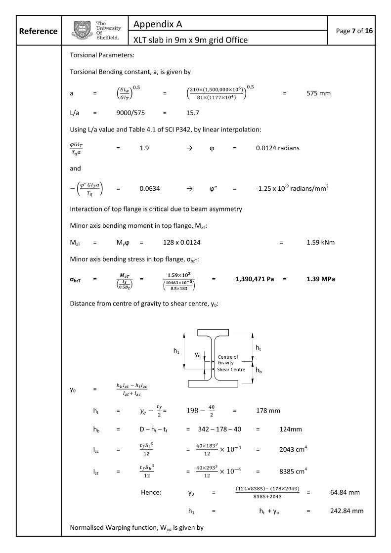
Appendix A
XLT slab in 9m x 9m grid Office Reference Page 7 of 16
Torsional Parameters:
Torsional Bending constant, a, is given by
a =
=
= 575 mm
L/a = 9000/575 = 15.7
Using L/a value and Table 4.1 of SCI P342, by linear interpolation:
= 1.9 → ϕ = 0.0124 radians
and
= 0.0634 → ϕ” = -1.25 x 10⁻⁹ radians/mm2
Interaction of top flange is critical due to beam asymmetry
Minor axis bending moment in top flange, MzT:
MzT = Myϕ = 128 x 0.0124 = 1.59 kNm
Minor axis bending stress in top flange, σbzT:
σbzT =
=
= 1,390,471 Pa = 1.39 MPa
Distance from centre of gravity to shear centre, y0:
y0 =
ht =
=
= 178 mm
hb = D – ht – tf = 342 – 178 – 40 = 124mm
Izc =
=
= 2043 cm4
Izt =
=
= 8385 cm4
Hence: y0 =
= 64.84 mm
h1 = ht + yo = 242.84 mm
Normalised Warping function, Wno is given by
yo h1
hb
ht

Appendix A
XLT slab in 9m x 9m grid Office Reference Page 8 of 16
Wo =
=
= 22,219 mm2
Warping stress, σw can be calculated as
σw = E.Wno.|ϕ”| = (210x109) x 22,219 x (1.25x10-9) = 5,832,487 Pa = 5.83 MPa
Equivalent uniform moment factor, mLT = 0.925 for a non-destabilizing UDL
Finally, putting values into interaction formula for buckling:
Check Local Capacity of compression flange in combined bending and torsion
σby + σbzT + σW ≤ fy ( = 355 MPa)
σby =
=
= 55.2 MPa
σby + σbzT + σW = 55.2 + 1.39 + 5.83 = 62.4MPa OK
Construction Load Case 1 is OK for buckling and local capacity of compression flange
Case 2: XLT slab on both sides, construction loading on one side of ASB only.
Assume bearing length of 40mm for design
Imposed UDL, qk = 0.5 x 4.5m = 2.25 kN/m
Permanent Load (slab) = Slab unit weight = 4.7 x (260/1000) = 1.22 kN/m2
Permanent Load (beam ) = 1.92 kN/m
Permanent UDL, gk = slab + beam = (1.22 x 9m) + 1.92 = 12.9 kN/m
BS 5950-1
Table 18

Appendix A
XLT slab in 9m x 9m grid Office Reference Page 9 of 16
fd.1 = γG.gk + γQ1. ψ0.qk = (1.35 x 12.9) + (1.5 x 0.7 x 2.25) = 19.8 kN/m
fd.2 = ξ γG.gk + γQ1.qk = (0.925 x 1.35 x 12.9) + (1.5 x 2.25) = 19.5 kN/m
fd = max(fd.1; fd.2) = 19.8 kN/m
Lateral Torsional Buckling (LTB) for combined bending and tension
Verify against interaction formula:
Major axis moment, My =
=
= 200 kNm
Torsion Load = 4.5m x 9m x (1.5 x 0.5) = 30.4 kN
Applied torsion, Tq = 30.4 x (126.5/103) = 3.85 kNm
Torsion Parameters:
As before,
L/a = 9000/575 = 15.7
= 1.9
= 0.0634
Under new torsion loads and value of Tq,
ϕ = 4.4 x10⁻³ radians
ϕ” = -4.45 x 10⁻¹⁰ radians/mm2
Minor axis bending moment in top flange, MzT:
MzT = Myϕ = 200 x 4.4 x10-3 = 0.88 kNm
Minor axis bending stress in top flange, σbzT:
σbzT =
=
= 769,569 Pa = 0.77 MPa
Eq. 6.10b
BS EN 1990
Eq. 6.10a
BS EN 1990

Appendix A
XLT slab in 9m x 9m grid Office Reference Page 10 of 16
Warping stress, σw:
σw = E.Wno.|ϕ”| = (210x109) x 22,219 x (4.45 x 10-10) = 2,076,365 Pa = 2.08 MPa
Interaction Formula for buckling:
Check Local Capacity of compression flange in combined bending and torsion
σby + σbzT + σW ≤ fy ( = 355 MPa)
σby =
=
= 86.2 MPa
σby + σbzT + σW = 86.2 + 0.77 + 2.08 = 89.1 MPa OK
Construction Load Case 2 is OK for buckling and local capacity of compression flange
Construction Load case 3 is not critical as no torsion due to assumption of equal slab spans either
side of ASB.
A.4.3 Normal Stage
Imposed Load = Office Loading = 2.5 kN/m2
Case 1: Pattern Loading, super-permanent loading on both sides, imposed loading on one side of ASB
only.
Assume bearing length of 40mm for design
Imposed UDL, qk = 2.5 x 4.5m = 11.25 kN/m
Permanent Load (slab) = Slab unit weight = 4.7 x (260/1000) = 1.22 kN/m2
Permanent Load (beam ) = 1.92 kN/m
Permanent UDL, gk = (slab + superimposed) + beam = (1.22+0.5)x9m + 1.92 = 17.4 kN/m
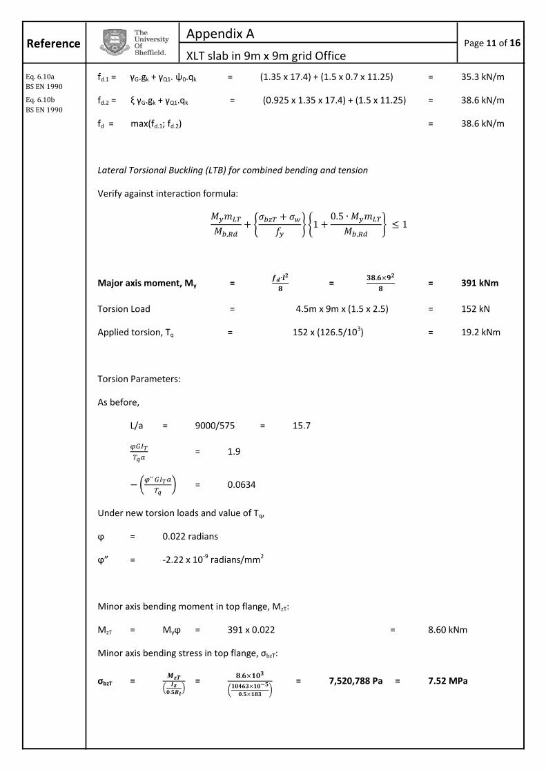
Appendix A
XLT slab in 9m x 9m grid Office Reference Page 11 of 16
fd.1 = γG.gk + γQ1. ψ0.qk = (1.35 x 17.4) + (1.5 x 0.7 x 11.25) = 35.3 kN/m
fd.2 = ξ γG.gk + γQ1.qk = (0.925 x 1.35 x 17.4) + (1.5 x 11.25) = 38.6 kN/m
fd = max(fd.1; fd.2) = 38.6 kN/m
Lateral Torsional Buckling (LTB) for combined bending and tension
Verify against interaction formula:
Major axis moment, My =
=
= 391 kNm
Torsion Load = 4.5m x 9m x (1.5 x 2.5) = 152 kN
Applied torsion, Tq = 152 x (126.5/103) = 19.2 kNm
Torsion Parameters:
As before,
L/a = 9000/575 = 15.7
= 1.9
= 0.0634
Under new torsion loads and value of Tq,
ϕ = 0.022 radians
ϕ” = -2.22 x 10⁻⁹ radians/mm2
Minor axis bending moment in top flange, MzT:
MzT = Myϕ = 391 x 0.022 = 8.60 kNm
Minor axis bending stress in top flange, σbzT:
σbzT =
=
= 7,520,788 Pa = 7.52 MPa
Eq. 6.10b
BS EN 1990
Eq. 6.10a
BS EN 1990

Appendix A
XLT slab in 9m x 9m grid Office Reference Page 12 of 16
Warping stress, σw:
σw = E.Wno.|ϕ”|= (210x109) x 22,219 x (2.22 x 10-9) = 10,358,498 Pa = 10.4 MPa
Interaction Formula for buckling:
Check Local Capacity of compression flange in combined bending and torsion
σby + σbzT + σW ≤ fy ( = 355 MPa)
σby =
=
= 169 MPa
σby + σbzT + σW = 169 + 10.4 + 7.52 = 187 MPa OK
Normal Stage pattern loading is OK for buckling and local capacity of compression flange
Case 2: Maximum loading
For this load case, need only check against buckling
capacity and shear failure
Imposed UDL, qk = 2.5 x 9m = 22.5 kN/m
Permanent Load (slab) = Slab unit weight = 4.7 x (260/1000) = 1.22 kN/m2
Permanent Load (beam ) = 1.92 kN/m
Permanent UDL, gk = (slab + superimposed) + beam = (1.22+0.5)x9m + 1.92 = 17.4 kN/m
fd.1 = γG.gk + γQ1. ψ0.qk = (1.35 x 17.4) + (1.5 x 0.7 x 22.5) = 47.1 kN/m
fd.2 = ξ γG.gk + γQ1.qk = (0.925 x 1.35 x 17.4) + (1.5 x 22.5) = 55.5 kN/m
fd = max(fd.1; fd.2) = 55.5 kN/m
Eq. 6.10b
BS EN 1990
Eq. 6.10a
BS EN 1990

Appendix A
XLT slab in 9m x 9m grid Office Reference Page 13 of 16
Major axis moment, My =
=
= 562 kNm
Buckling Capacity
1.0 :
Shear Capacity
Design shear force, Vd =
=
= 250kN
Design shear resistance Vpl,Rd =
Av = A – (Bbtf + Bttf) + (tw + 2r)tf = (249x100) – (293x40 + 183x40)+(20 +2x27)x40 = 8820mm2
Vpl,Rd =
= 1,807,741 N = 1,807 kN
1.0 :
A.4.4 Serviceability Checks
Composite behaviour of the timber slab and steel beam is assumed for deflection checks at the normal
loading stage. The 2nd moment of area of the composite beam section must be found for use in the
calculations.
Effective Breadth
When using concrete slabs, with infill concrete around the web of the beam, effective breadth is
assumed as span/32 to either side of the beam. To replicate this for the timber case, without infill, the
effective breadth, beff is taken as
beff =
=
= 430mm
This accounts for the area between the slab and the ASB web being empty.
Eq. 6.18
BS EN 1993-1-1
Variation on
clause 6.2.6(3)
BS EN 1993-1-1
SCI P342, section
4.3
D
Bb - 160
ye dNA
span/16
d

Appendix A
XLT slab in 9m x 9m grid Office Reference Page 14 of 16
Modular Ratio
The modular ratio, n, is a ratio of the Young’s Moduli of the two materials in the composite section and
is used to make their different properties compatible in calculations. By using the modular ratio it is
possible to transform the cross-section area of one material into an equivalent area of the other
material. This additional equivalent area is used to calculate the enhancement in behaviour of the two
materials acting compositely versus the one material acting alone.
To transform the timber slab into an equivalent area of steel, the modular ratio is given by,
n =
Due to its susceptibility to creep, the deflection of timber elements normally consists of two parts – an
instantaneous deflection, and an additional long term deformation. However, due to the presence of a
substantially stiffer element, the ASB, and the use of composite theory, it is thought sufficient to
account for loss of stiffness of the timber over time when calculating the Young’s Modulus.
As such, Etimber = Ed,SLS =
=
= 6.67 GPa
n =
= 31.5
1st Moment of Area to find composite neutral axis depth, ycomp
About the top of the slab, in steel units...
Where AASB is the cross sectional area of the ASB, and dNA is the distance between the top of the slab
and the neutral axis of the ASB, and is given by:
dNA = = 198 – (342 – 40 – 260) = 156mm
→ ycomp = 152.8 mm
Composite 2nd Moment of Area, using Parallel Axis Theorem
In steel units...
Where IASB is the 2nd moment of area for the ASB. Substituting values into the formula,
→ Icomp = 48,078 cm4
Construction stage deflection check (bare steel properties)
Eq. 2.7 & Table 3.2
BS EN 1995-1-1

Appendix A
XLT slab in 9m x 9m grid Office Reference Page 15 of 16
Self weight deflection (slab on both sides):
ωSLS = slab + beam = (1.22 x 9) + 1.92 = 12.9 kN/m
Deflection during construction, δc, given by:
δc =
=
= 0.0114 m = 11.4 mm
Construction Deflection limit = span/200 = 9000/200 = 45mm OK
Normal stage deflection check (composite properties)
Imposed load deflection check
ωSLS = imposed load = 2.5 x 9m = 22.5 kN/m
δIMP =
=
= 0.0190 m = 19.0 mm
Imposed Deflection limit = span/360 = 9000/360 = 25mm OK
Super-imposed permanent load deflection check
ωSLS = superimposed = 0.5 x 9m = 4.5 kN/m
δSUP =
=
= 0.00381 m = 3.81 mm
As deflections arising during construction are corrected on site, total deflection consists solely of those
due to imposed load and superimposed permanent load:
Total deflection = δIMP + δSUP = 19.0 + 3.81 = 22.8 mm
Check: 22.8 < span/200 (= 25mm) Hence OK
300 ASB 196 is verified for this situation and loading

Appendix A
XLT slab in 9m x 9m grid Office Reference Page 16 of 16
A.4.5 Tie Beam
Assuming an internal bay,
Design Tie force, Ti = 0.8(gk + ψ1qk)sL
Where
s is the tie spacing = 9 m
L is the tie span = 9 m
ψ1 = 0.5
gk slab weight + superimposed = 1.72 kN/m2
qk imposed load = 2.5 kN/m2
Substituting, Ti = 192 kN
Minimum section area required =
=
= 5.41 cm2
To avoid visible sag, min. section depth = span/40 = 9000/40 = 225mm
To meet requirements, use 165x267x33 T-section as structural tie.
Eq. A.1.
BS EN 1991-1-7