structural health monitoring and maintenance aided … health monitoring and maintenance aided by...
TRANSCRIPT

Structural health monitoring and maintenance aided by building information modelling and repair information tools
D. Huston, D. Burns & J. Razinger School of Engineering, University of Vermont, USA
Abstract
This paper discusses the use of Building Information Modelling (BIM) as a backbone of Structural Health Monitoring and Maintenance (SHM2). The practice of SHM2 attempts to enhance the performance, serviceability and resilience of structural systems by integrating structural sensing, assessment and prognosis with decision-making and implementation of maintenance and repair. A significant portion of the activity collects, stores, transmits and processes information from multiple sources, typically in heterogeneous formats. This information includes visual inspection reports, sensor data, structural configuration, design documents, repair procedures, maintenance history, and economic considerations. Managing and using these information streams usually follows an ad hoc path with a custom application for each structure. A viable alternative might be to organize the information flow into a comprehensive BIM-SHM2 framework. This paper presents a two-pronged approach to this end. The first prong is top-down beginning with a draft Level of Detail (LOD) hierarchy beginning with low-level (100) descriptions of sensor and repair designs, followed by medium-level (200–300) organized representations of sensor data mapped onto BIM structural layouts, followed by higher-level analysis and decision-influencing representations. The second prong is a bottom-up approach in which develops a BIM-SHM2 framework as part of a series of examples and applications, primarily derived from field tests on bridges and buildings. Also included is a presentation of a Repair Information Decision Making (RIMD) tool for concrete structures, and initial forays integrating with BIM and SHM2. Keywords: structural health monitoring, repair information, concrete, BIM.
www.witpress.com, ISSN 1743-3541 (on-line) WIT Transactions on Ecology and The Environment, Vol 204, © 2016 WIT Press
doi:10.2495/SC160731
This paper is part of the Proceedings of the 11 International Conference th
on Urban Regeneration and Sustainability (SC 2016) www.witconferences.com

1 Introduction
Structural health monitoring and maintenance (SHM2) is largely practiced as a combination of information processing and decision-making as the backdrop underpinning remedial and construction actions (Figure 1).
Figure 1: Circular flow of structural health monitoring and maintenance activities.
Managing structural health involves [1]:
1. Structural Observations and Measurement: Visual observations and those taken with a variety of transducers and instruments provide data on structural conditions.
2. Information Management: Information from structural observations, construction documents, maintenance records, future usage plans, and finances form a diverse set of data. Storing, managing and mining the data can produce useful information.
3. Condition Assessment: Relatively quick processing of the data, either with the human mind, and/or aided by machine intelligence provides a quick assessment of condition.
4. Decision-Making and Planning: What are the best strategies for maintaining structural health, possibly including analysis of short duration and lifetime costs of ownership? Options range among scheduling more observations and assessments, minor repairs, major repairs, and reconstruction.
5. Implementation of Repairs: Repair, reconstruct and replace the structure. Attempt to schedule so as to minimize costs, e.g. try to avoid emergency repairs.
6. Assessment of Repair and Maintenance Performance: Determine how well the repairs perform.
898 The Sustainable City XI
www.witpress.com, ISSN 1743-3541 (on-line) WIT Transactions on Ecology and The Environment, Vol 204, © 2016 WIT Press
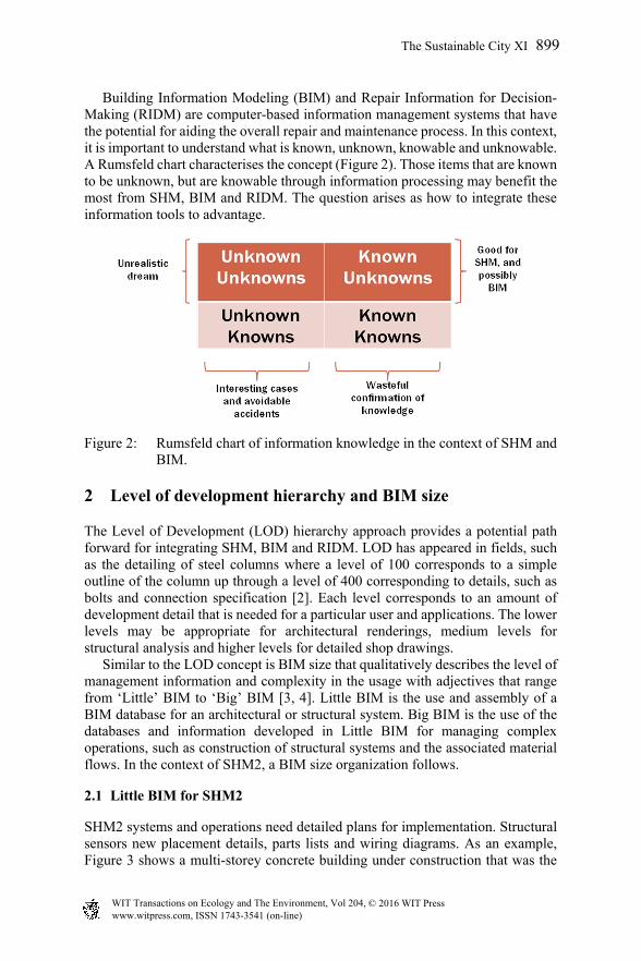
Building Information Modeling (BIM) and Repair Information for Decision-Making (RIDM) are computer-based information management systems that have the potential for aiding the overall repair and maintenance process. In this context, it is important to understand what is known, unknown, knowable and unknowable. A Rumsfeld chart characterises the concept (Figure 2). Those items that are known to be unknown, but are knowable through information processing may benefit the most from SHM, BIM and RIDM. The question arises as how to integrate these information tools to advantage.
Figure 2: Rumsfeld chart of information knowledge in the context of SHM and BIM.
2 Level of development hierarchy and BIM size
The Level of Development (LOD) hierarchy approach provides a potential path forward for integrating SHM, BIM and RIDM. LOD has appeared in fields, such as the detailing of steel columns where a level of 100 corresponds to a simple outline of the column up through a level of 400 corresponding to details, such as bolts and connection specification [2]. Each level corresponds to an amount of development detail that is needed for a particular user and applications. The lower levels may be appropriate for architectural renderings, medium levels for structural analysis and higher levels for detailed shop drawings. Similar to the LOD concept is BIM size that qualitatively describes the level of management information and complexity in the usage with adjectives that range from ‘Little’ BIM to ‘Big’ BIM [3, 4]. Little BIM is the use and assembly of a BIM database for an architectural or structural system. Big BIM is the use of the databases and information developed in Little BIM for managing complex operations, such as construction of structural systems and the associated material flows. In the context of SHM2, a BIM size organization follows.
2.1 Little BIM for SHM2
SHM2 systems and operations need detailed plans for implementation. Structural sensors new placement details, parts lists and wiring diagrams. As an example, Figure 3 shows a multi-storey concrete building under construction that was the
The Sustainable City XI 899
www.witpress.com, ISSN 1743-3541 (on-line) WIT Transactions on Ecology and The Environment, Vol 204, © 2016 WIT Press

subject of an instrumented study of monitoring of vertical shoring loads (Figure 4). Inserting the design plans for such an instrumentation system into a BIM database for the structure, probably in a manner similar to electrical or mechanical systems, would be a Little BIM application to SHM2.
Figure 3: Boston Museum Towers under construction.
Figure 4: Load-measuring instrumented shoring system in Boston Museum Towers.
900 The Sustainable City XI
www.witpress.com, ISSN 1743-3541 (on-line) WIT Transactions on Ecology and The Environment, Vol 204, © 2016 WIT Press

2.2 Little bigger BIM
Gathering and processing data from measured data and using BIM as a framework for laying out the data is a possible bigger application. For example, Figure 5 shows load data from a multi-storey stack of shores and the notable daily thermal loading. BIM may provide a framework for attaching the collected data to a rendering of the structure for more detailed analysis and conceptualization.
Figure 5: Multi-storey shore load data collected over 5 days showing thermal loading cycles.
Another aspect is to feed data directly into a BIM model directly by using electro-optical instruments for 3-D renderings of existing structures. This can be useful in constructing and augmenting existing BIM models. Three primary instruments for optical shape capture are lidar, stereo cameras and free-form multi-position camera methods (Figure 6). Lidar transmits and receives short laser pulses to and from the surface of the structure. The laser illuminates a small diameter point on the surface. Direction of transmission along with time of flight locates the illuminated point in 3-D. Scanning the illumination over the surface creates the 3-D rendering. Lidar has some limitations. The duration of the laser pulse limits the accuracy of the time of flight distance measurement and shadowing prevents a full 360° reconstruction from a single position of the lidar. Stereo Cameras use the geometry of two cameras with a fixed separation distance with relatively simple photogrammetric analysis to locate surface points in 3-D from a stereo pair of images of the object. The technique requires software with sufficient intelligence to correlate points in both images as being the same point on the surface of the structure. Shadowing prevents full 3-D rendering from a single camera position. Multi-Position Single Camera – This technique uses a free-form positioning scheme for the camera with images from multiple positions that encircle the structure. Sophisticated photogrammetric software reconstructs the 3-D rendering by fusing the data from the multiple images. This method has the advantage of requiring minimal instrument setup, but the software is somewhat sensitive to spurious image contents, such as passing vehicles and moving shadows.
The Sustainable City XI 901
www.witpress.com, ISSN 1743-3541 (on-line) WIT Transactions on Ecology and The Environment, Vol 204, © 2016 WIT Press
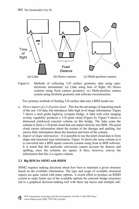
(a) Lidar. (b) Stereo camera. (c) Multi-position camera.
Figure 6: Methods of collecting 3-D surface geometry data using opto-electronic instruments: (a) Lidar using time of flight; (b) Stereo cameras using fixed camera geometry; (c) Multi-position camera system using freeform geometry and software reconstruction.
Two primary methods of feeding 3-D surface data into a BIM model are:
a. Direct import of a 3-D point cloud – This has the advantage of importing much of the raw 3-D data, but introduces little high level shape information. Figure 7 shows a steel girder highway overpass bridge. A lidar with color imaging overlay capability produces a 3-D point cloud (Figure 8). Figure 9 shows a distressed reinforced concrete column on this bridge. The lidar scans the column to form a 3-D point cloud that can import directly into BIM. The point cloud carries information about the texture of the damage and spalling, but carries little information about the function and form of the column.
b. Import of shape information – It is possible to use the point cloud data to form shape and structural type information. Figure 10 shows the same column as it is converted into a BIM square concrete column using Scan to BIM software. It is noted that this particular conversion cannot account for distress and spalling, since the columns are square. It does, however, convey the information that this is a square column.
2.3 Big BIM for SHM2 with RIDM
SHM2 requires making decisions about how best to maintain a given structure based on the available information. The type and scope of available structural repairs are quite varied with many options. A recent effort to produce an RIMD system to make better use of the available options for concrete bridge structures led to a graphical decision-making tool with three top layers and multiple sub-
902 The Sustainable City XI
www.witpress.com, ISSN 1743-3541 (on-line) WIT Transactions on Ecology and The Environment, Vol 204, © 2016 WIT Press
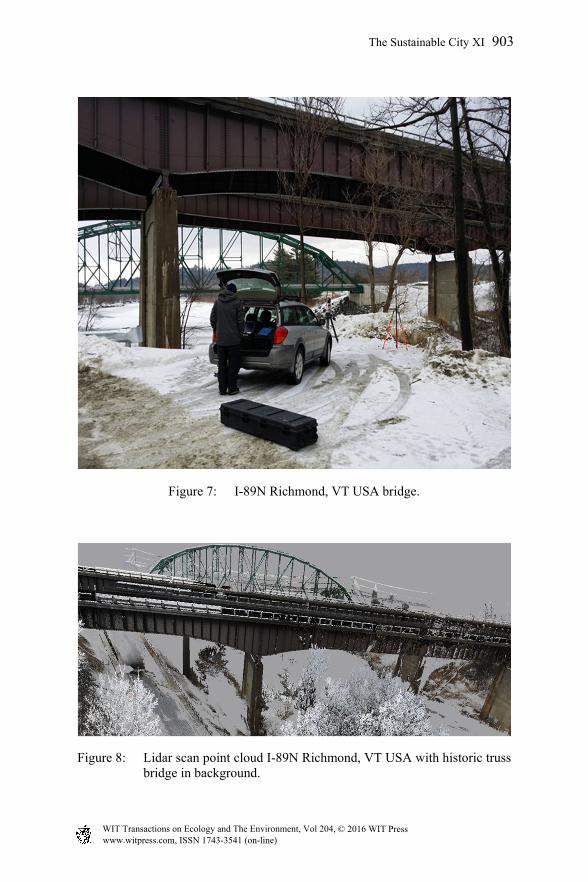
Figure 7: I-89N Richmond, VT USA bridge.
Figure 8: Lidar scan point cloud I-89N Richmond, VT USA with historic truss bridge in background.
The Sustainable City XI 903
www.witpress.com, ISSN 1743-3541 (on-line) WIT Transactions on Ecology and The Environment, Vol 204, © 2016 WIT Press
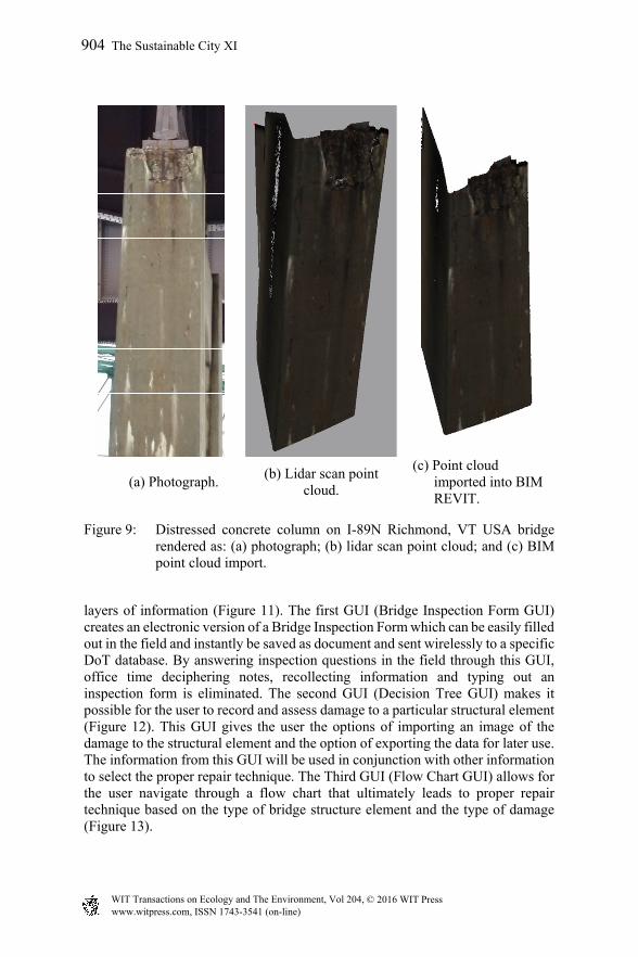
(a) Photograph. (b) Lidar scan point
cloud.
(c) Point cloud imported into BIM REVIT.
Figure 9: Distressed concrete column on I-89N Richmond, VT USA bridge rendered as: (a) photograph; (b) lidar scan point cloud; and (c) BIM point cloud import.
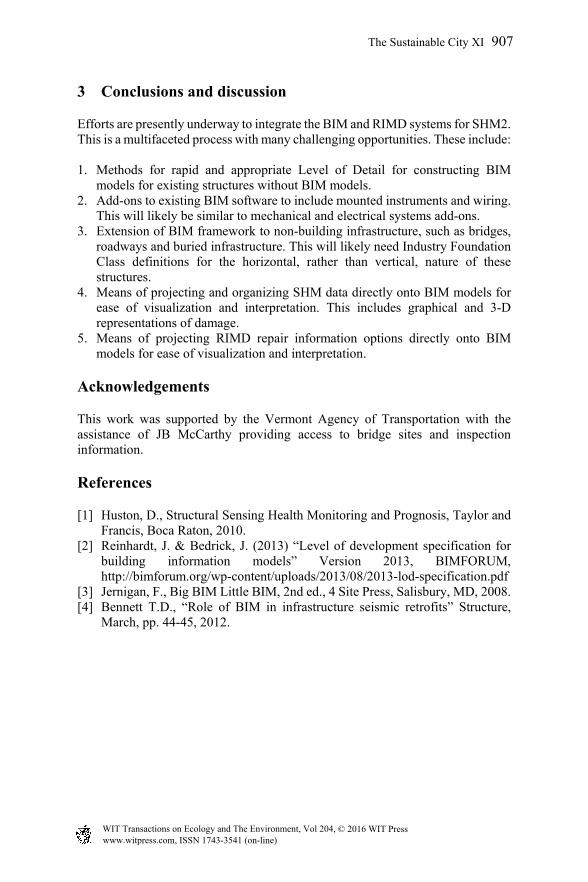
layers of information (Figure 11). The first GUI (Bridge Inspection Form GUI) creates an electronic version of a Bridge Inspection Form which can be easily filled out in the field and instantly be saved as document and sent wirelessly to a specific DoT database. By answering inspection questions in the field through this GUI, office time deciphering notes, recollecting information and typing out an inspection form is eliminated. The second GUI (Decision Tree GUI) makes it possible for the user to record and assess damage to a particular structural element (Figure 12). This GUI gives the user the options of importing an image of the damage to the structural element and the option of exporting the data for later use. The information from this GUI will be used in conjunction with other information to select the proper repair technique. The Third GUI (Flow Chart GUI) allows for the user navigate through a flow chart that ultimately leads to proper repair technique based on the type of bridge structure element and the type of damage (Figure 13).
904 The Sustainable City XI
www.witpress.com, ISSN 1743-3541 (on-line) WIT Transactions on Ecology and The Environment, Vol 204, © 2016 WIT Press
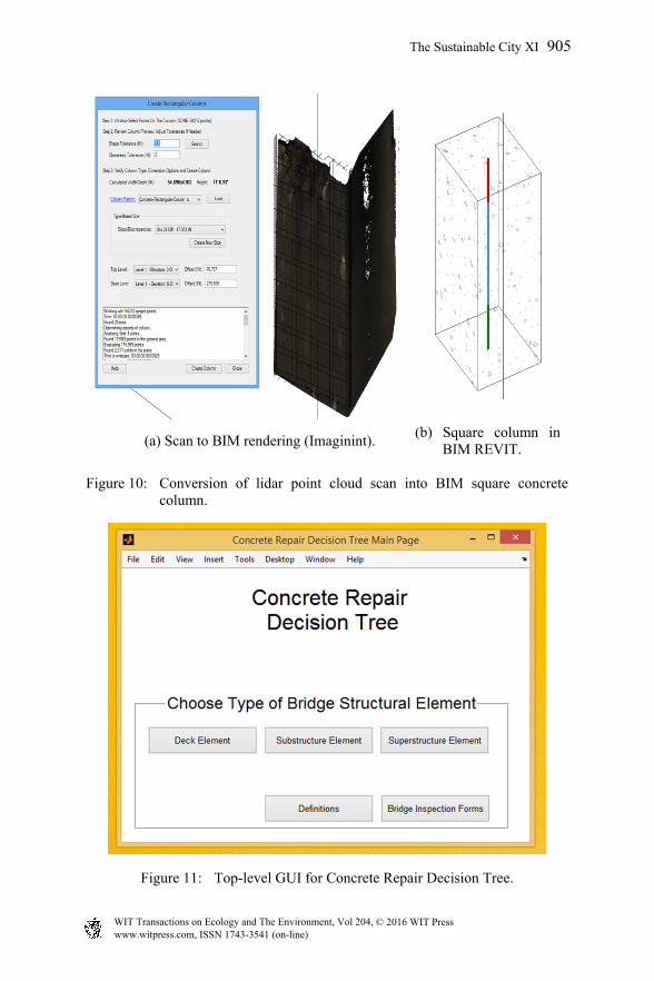
(a) Scan to BIM rendering (Imaginint). (b) Square column in
BIM REVIT.
Figure 10: Conversion of lidar point cloud scan into BIM square concrete column.
Figure 11: Top-level GUI for Concrete Repair Decision Tree.
The Sustainable City XI 905
www.witpress.com, ISSN 1743-3541 (on-line) WIT Transactions on Ecology and The Environment, Vol 204, © 2016 WIT Press

Figure 12: Portion of Concrete Repair Decision Tree for expansion joints.
Figure 13: Definitions GUI for navigating to concrete repair options.
906 The Sustainable City XI
www.witpress.com, ISSN 1743-3541 (on-line) WIT Transactions on Ecology and The Environment, Vol 204, © 2016 WIT Press
3 Conclusions and discussion
Efforts are presently underway to integrate the BIM and RIMD systems for SHM2. This is a multifaceted process with many challenging opportunities. These include: 1. Methods for rapid and appropriate Level of Detail for constructing BIM
models for existing structures without BIM models. 2. Add-ons to existing BIM software to include mounted instruments and wiring.
This will likely be similar to mechanical and electrical systems add-ons. 3. Extension of BIM framework to non-building infrastructure, such as bridges,
roadways and buried infrastructure. This will likely need Industry Foundation Class definitions for the horizontal, rather than vertical, nature of these structures.
4. Means of projecting and organizing SHM data directly onto BIM models for ease of visualization and interpretation. This includes graphical and 3-D representations of damage.
5. Means of projecting RIMD repair information options directly onto BIM models for ease of visualization and interpretation.
Acknowledgements
This work was supported by the Vermont Agency of Transportation with the assistance of JB McCarthy providing access to bridge sites and inspection information.
References
[1] Huston, D., Structural Sensing Health Monitoring and Prognosis, Taylor and Francis, Boca Raton, 2010.
[2] Reinhardt, J. & Bedrick, J. (2013) “Level of development specification for building information models” Version 2013, BIMFORUM, http://bimforum.org/wp-content/uploads/2013/08/2013-lod-specification.pdf
[3] Jernigan, F., Big BIM Little BIM, 2nd ed., 4 Site Press, Salisbury, MD, 2008. [4] Bennett T.D., “Role of BIM in infrastructure seismic retrofits” Structure,
March, pp. 44-45, 2012.
The Sustainable City XI 907
www.witpress.com, ISSN 1743-3541 (on-line) WIT Transactions on Ecology and The Environment, Vol 204, © 2016 WIT Press