structural engineering parametric study of web shear cracking
TRANSCRIPT

Structural Engineering
Concrete Structures Kristian Edekling & Lars Rettne
Parametric Study of Web Shear Cracking
Lars Rettne
Based on the Master’s Project “Improved Design Method for Web Shear Tension Failure in Hollow Core Units” in the International Master’s Programme Structural Engineering

Structural Engineering
Concrete Structures Kristian Edekling & Lars Rettne
Web Shear Tension Failure in Hollow Core Units

Structural Engineering
Concrete Structures Kristian Edekling & Lars Rettne
Problem Description
”In the present standard the guidance on howto calculate shear tension capacity is not detailed enough and a more precise methodis needed”

Structural Engineering
Concrete Structures Kristian Edekling & Lars Rettne
Aim of the Project
• Create finite element (FE) models of single hollow core units
• Perform calculations using Yang’s methodof single hollow core units
• Compare the shear capacity and location of the critical point between the two methods

Structural Engineering
Concrete Structures Kristian Edekling & Lars Rettne
Critical Point= The point where web shear cracking starts

Structural Engineering
Concrete Structures Kristian Edekling & Lars Rettne
Collaboration
• This project was initiated by Strängbetong, which is the largest hollow core unit producer in Sweden

Structural Engineering
Concrete Structures Kristian Edekling & Lars Rettne
Hollow Core Floors
Hollow core floors consist of hollow core units
Hollow core floor Hollow core unit

Structural Engineering
Concrete Structures Kristian Edekling & Lars Rettne
Web Shear Tension Failure in Hollow Core Units
Uncracked cross-section σ1 < fctm
σ1
σ1 = Principal stressfctm = Mean tensile strength of concrete

Structural Engineering
Concrete Structures Kristian Edekling & Lars Rettne
Web Shear Tension Failure in Hollow Core Units
Web shear cracking σ1 = fctm
Immediately failure (brittle)

Structural Engineering
Concrete Structures Kristian Edekling & Lars Rettne
Shear Capacity with Respect to Web Shear Tension Failure
• Failure when the concrete tensile strength is reached, σ1 = fctm
• The principal stresses are dependent of the shear and normal stresses, σ1 = σ1(σx, τ)

Structural Engineering
Concrete Structures Kristian Edekling & Lars Rettne
Shear Stress Calculations in Prestressed Members
Yang’s (new)Traditional (present)
P0i P0i P0iP0i
x xσp

Structural Engineering
Concrete Structures Kristian Edekling & Lars Rettne
Shear Stress Calculations in Prestressed Members
Yang’s (new)Traditional (present)
)()()(
),(I cpw
cpcpcpcp zbI
xVzSzx =τ )(
)()()(
),( 0
I dxdPf
zbIxVzS
zx i
cpw
cpcpcpcp +=τ
The shape is taken into account
Structural Engineering
Concrete Structures Kristian Edekling & Lars Rettne
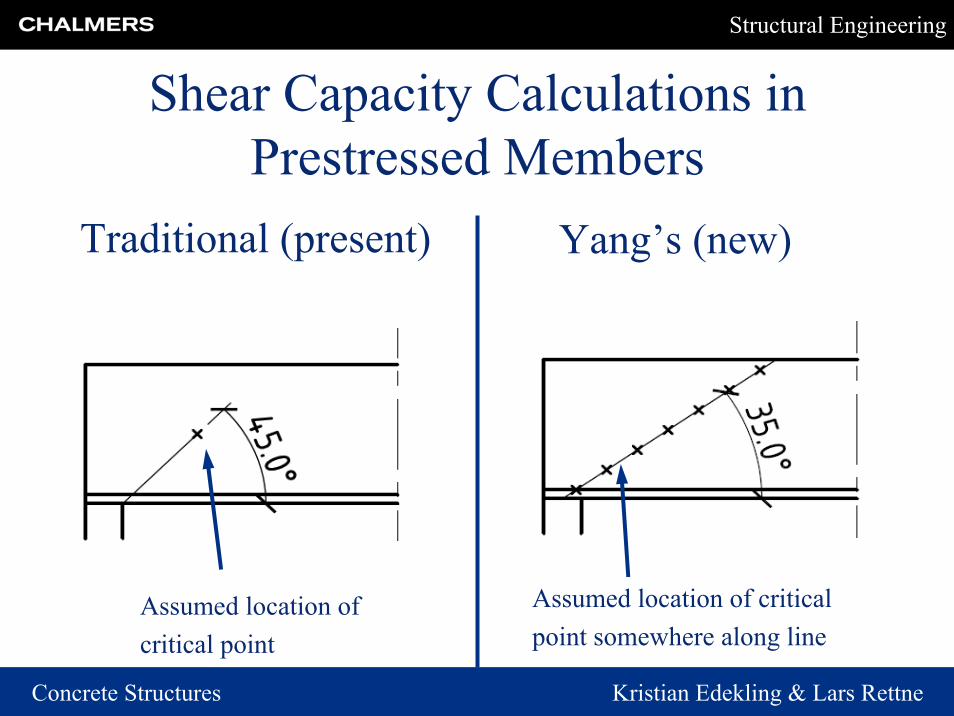
Shear Capacity Calculations in Prestressed Members
Yang’s (new)Traditional (present)
Assumed location of criticalpoint somewhere along line
Assumed location ofcritical point

Structural Engineering
Concrete Structures Kristian Edekling & Lars Rettne
Reference Case – Principal Sketch
Prestressing strand
Cross-section
Self weight and imposed load
Structural Engineering
Concrete Structures Kristian Edekling & Lars Rettne
Parametric Study
• Prestressing strand arrangement• Prestressing strand amount• Prestress• Concrete strength class• Concrete strength at strand release• Prestress transfer function• Type of cross-section

Structural Engineering
Concrete Structures Kristian Edekling & Lars Rettne
FE Model
Steel strands: Truss finite elementsStiff steel support plate: Solid finite elements
Concrete part: Solid finite elements

Structural Engineering
Concrete Structures Kristian Edekling & Lars Rettne
FE Model - Boundary Conditions
Roller support
Solid concrete part
Stiff support plate
Line where the boundary conditions were applied

Structural Engineering
Concrete Structures Kristian Edekling & Lars Rettne
FE Model - Boundary Conditions: Symmetry Planes
Boundary conditions along transversal symmetry plane
Boundary conditions along longitudinal symmetry plane

Structural Engineering
Concrete Structures Kristian Edekling & Lars Rettne
FE Model - LoadsSelf weight & Imposed load (pressure)
Initial stress from prestressing (initial condition)

Structural Engineering
Concrete Structures Kristian Edekling & Lars Rettne
FE Model - Mesh
dense mesh (25 mm)
Non-critical region coarse mesh (200 mm)
Critical region

Structural Engineering
Concrete Structures Kristian Edekling & Lars Rettne
Results – FE MethodPrincipal Stresses in the Reference case
Critical point

Structural Engineering
Concrete Structures Kristian Edekling & Lars Rettne
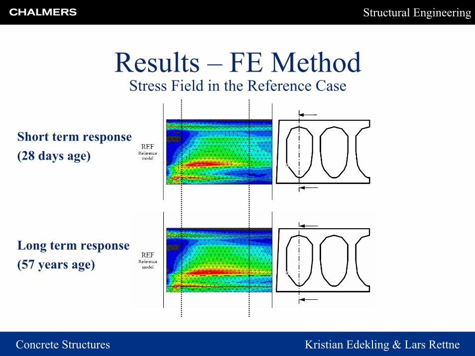
Results – FE MethodStress Field in the Reference Case
Short term response(28 days age)
Long term response(57 years age)
Structural Engineering
Concrete Structures Kristian Edekling & Lars Rettne
Results – FE MethodStress Field in the Reference Case
Short term response(28 days age)
Long term response(57 years age)
Structural Engineering
Concrete Structures Kristian Edekling & Lars Rettne
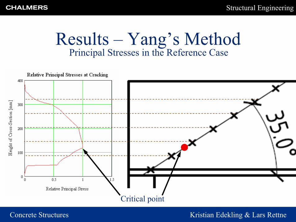
Results – Yang’s Method
Critical point
Principal Stresses in the Reference Case

Structural Engineering
Concrete Structures Kristian Edekling & Lars Rettne
Shear CapacitySupport Reaction at Web Shear Cracking
Lin Yang, 35° Critical Path from Mid Support
100
200
300
400
500
600
REFSTIFF
PSArPSAm8PSAm12 PS CC
CSAR
PTFTOCS
TOCS-PSAr
Supp
ort R
eact
ion
[kN
]
t=28 days t=57 years
Support Reaction at Web Shear CrackingFE Analyses
100
200
300
400
500
600
REFSTIFF
PSArPSAm8PSAm12 PS CC
CSAR
PTFTOCS
TOCS-PSAr
Supp
ort R
eact
ion
[kN
]
t=28 days t=57 years

Structural Engineering
Concrete Structures Kristian Edekling & Lars Rettne
Shear CapacityRelative Support Reactions at Web Shear Cracking
RLin Yang 35°/RFE Analyses
0,90
0,95
1,00
1,05
1,10
REF
STIFF PSAr
PSAm8
PSAm12 PS CC
CSAR
PTF
TOCSTOCS-PS
Ar
RLi
n Y
ang
35°/R
Aba
qus [
]
t=28 dayst=57 years
Comparison between FEM and Yang’s Method
Yang’s method unconservative
Yang’s method conservative

Structural Engineering
Concrete Structures Kristian Edekling & Lars Rettne
Location of Critical PointPosition of Critical Point For the Reference Model (REF)
Comparison Between FE Analyses / Yang
00,020,040,060,08
0,10,120,140,16
0 0,05 0,1 0,15 0,2 0,25
Horizontal Position from Mid Support [m]
Ver
tical
Pos
ition
from
-Bo
ttom
Uni
t [m
]
REF 28 days, FEM REF 57 years, FEMREF 28 days, Yang REF 57 years, Yang
Position of Critical Point For the Model with Stiffener (STIFF)Comparison Between FE Analyses / Yang
00,02
0,040,060,08
0,10,12
0,140,16
0 0,05 0,1 0,15 0,2 0,25 0,3
Horizontal Position from Mid Support [m]
Ver
tical
Pos
ition
from
Botto
m U
nit [
m]
STIFF 28 days, FEMSTIFF 57 years, FEMSTIFF 28 days, YangSTIFF 57 years, YangREF 28 days, FEMREF 57 years, FEM
Position of Critical Point For the Model with Changed Prestressing Strand Arrangement (PSAr)
Comparison Between FE Analyses / Yang
PSAr 28 days, FEMREF 28 days, FEM
0
0,02
0,04
0,06
0,08
0,1
0,12
0,14
0,16
0 0,05 0,1 0,15 0,2 0,25 0,3
Horizontal Position from Mid Support [m]
Ver
tical
Pos
ition
from
Bot
tom
Uni
t [m
] PSAr 28 days, FEMPSAr 57 years, FEMPSAr 28 days, YangPSAr 57 years, YangREF 28 days, FEMREF 57 years, FEM
Position of Critical Point For the Model with Changed Prestressing Strand Amount (PSAm8)
Comparison Between FE Analyses / Yang
PSAm8 28 days, FEMPSAm8 57 years, FEM
0
0,05
0,1
0,15
0,2
0,25
0 0,05 0,1 0,15 0,2 0,25 0,3
Horizontal Position from Mid Support [m]
Ver
tical
Pos
ition
from
Bot
tom
Uni
t [m
]
PSAm8 28 days, FEMPSAm8 57 years, FEMPSAm8 28 days, YangPSAm8 57 years, YangREF 28 days, FEMREF 57 years, FEM
Position of Critical Point For the Model with Changed Prestressing Strand Amount (PSAm12)
Comparison Between FE Analyses / Yang
PSAm12 28 days, Yang
PSAm12 57 years, Yang
0
0,05
0,1
0,15
0,2
0,25
0 0,05 0,1 0,15 0,2 0,25 0,3
Horizontal Position from Mid Support [m]
Ver
tical
Pos
ition
from
Bot
tom
Uni
t [m
]
PSAm12 28 days, FEMPSAm12 57 years, FEMPSAm12 28 days, YangPSAm12 57 years, YangREF 28 days, FEMREF 57 years, FEM
Position of Critical Point For the Model with Changed Prestress (PS)Comparison Between FE Analyses / Yang
PS 28 days, FEM
PS 57 years, FEM
REF 28 days, FEM
REF 57 years, FEM
0
0,02
0,04
0,06
0,08
0,1
0,12
0,14
0,16
0 0,05 0,1 0,15 0,2 0,25
Horizontal Position from Mid Support [m]V
ertic
al P
ositi
on fr
omB
otto
m U
nit [
m]
PS 28 days, FEMPS 57 years, FEMPS 28 days, YangPS 57 years, YangREF 28 days, FEMREF 57 years, FEM
Position of Critical Point For the Model with Changed Concrete Class (CC)
Comparison Between FE Analyses / Yang
CC 28 days, FEMREF 28 days, FEM
0
0,02
0,04
0,06
0,08
0,1
0,12
0,14
0,16
0 0,05 0,1 0,15 0,2 0,25 0,3
Horizontal Position from Mid Support [m]
Ver
tical
Pos
ition
from
Bot
tom
Uni
t [m
]
CC 28 days, FEMCC 57 years, FEMCC 28 days, YangCC 57 years, YangREF 28 days, FEMREF 57 year, FEM
Position of Critical Point For the Model with Changed Concrete Strength at Strand Release (CSAR)
Comparison Between FE Analyses / Yang
CSAR 57 years, FEM
CSAR 28 days, YangCSAR 57 years, Yang
REF 57 years, FEM
0
0,02
0,04
0,06
0,08
0,1
0,12
0,14
0 0,05 0,1 0,15 0,2 0,25Horizontal Position from Mid Support [m]
Ver
tical
Pos
ition
from
Bot
tom
Uni
t [m
]
CSAR 28 days, FEMCSAR 57 years, FEMCSAR 28 days, YangCSAR 57 years, YangREF 28 days, FEMREF 57 years, FEM
Position of Critical Point For the Model with Changed Prestressing Transfer Fuction (PTF)
Comparison Between FE Analyses / Yang
0
0,02
0,04
0,06
0,08
0,1
0,12
0,14
0 0,05 0,1 0,15 0,2 0,25 0,3
Horizontal Position from Mid Support [m]
Ver
tical
Pos
ition
from
Bot
tom
Uni
t [m
]
PTF 57 years, FEMPTF 57 years, YangREF 57 years, FEM
Position of Critical Point For the Model with Changed Type of Cross-Section (TOCS)
Comparison Between FE Analyses / Yang
TOCS 28 days, YangTOCS 57 years, Yang
0
0,02
0,04
0,06
0,08
0,1
0,12
0,14
0 0,05 0,1 0,15 0,2 0,25
Horizontal Position from Mid Support [m]
Ver
tical
Pos
ition
from
Bot
tom
Uni
t [m
]
TOCS 28 days, FEMTOCS 57 years, FEMTOCS 28 days, YangTOCS 57 years, YangREF 28 days, FEMREF 57 years, FEM
Position of Critical Point For the Model with Changed Type of Cross-Section and Prestressing Strand Arrangement (TOCS-PSAr)
Comparison Between FE Analyses / Yang
TOCS-PSAr 28 daYang
TOCS-PSAr 57 yeYang0
0,02
0,04
0,06
0,08
0,1
0,12
0,14
0 0,05 0,1 0,15 0,2 0,25
Horizontal Position from Mid Support [m]
Ver
tical
Pos
ition
from
Bot
tom
Uni
t [m
]
TOCS-PSAr 2TOCS-PSAr 5TOCS-PSAr 2TOCS-PSAr 5REF 28 days, FREF 57 years,

Structural Engineering
Concrete Structures Kristian Edekling & Lars Rettne
Location of Critical PointFE Analyses
Horizontal and Vertical Location of Critical Point Independently of Web, t =28 days, FE Analyses
PSAm8
PSAm12
TOCS
REFPSAr
PSCCCSARSTIFF
TOCS-PSAr
0
0,05
0,1
0,15
0,2
0,25
0 0,05 0,1 0,15 0,2 0,25 0,3
Horizontal Distance from Middle Support [m]
Ver
tical
Dis
tanc
e fr
om
-B
otto
m E
dge
[m]
REF PSAr PSAm8 PSAm12PS CC CSAR PTFSTIFF TOCS TOCS-PSAr

Structural Engineering
Concrete Structures Kristian Edekling & Lars Rettne
Location of Critical PointYang’s Method
Horizontal and Vertical Location of Critical Point Independently of Web, t =28 days, Yang's Method
REF
PSAr
PSAm8
PSAm12PS
CCCSAR PTF STIFF
TOCSTOCS-PSAr
00,020,040,060,080,1
0,120,140,160,18
0 0,05 0,1 0,15 0,2 0,25 0,3
Horizontal Distance from Middle Support [m]
Ver
tical
Dist
ance
from
B
otto
m E
dge
[m]
REF PSAr PSAm8 PSAm12PS CC CSAR PTFSTIFF TOCS TOCS-PSAr

Structural Engineering
Concrete Structures Kristian Edekling & Lars Rettne
Location of Critical Point:Reference Case
Location of Critical Point For the Reference Case (REF)Comparison Between FE Analyses / Yang's Method
0
0,020,04
0,06
0,08
0,10,12
0,14
0,16
0 0,05 0,1 0,15 0,2 0,25
Horizontal Distance from Middle Support [m]
Ver
tical
Dis
tanc
e fr
om
-B
otto
m E
dge
[m]
REF 28 days, FEM REF 57 years, FEMREF 28 days, Yang REF 57 years, Yang

Structural Engineering
Concrete Structures Kristian Edekling & Lars Rettne
Location of Critical Point: Prestressing Strand Amount, PSAm8
Location of Critical Point For the Case with Changed Prestressing Strand Amount (PSAm8)
Comparison between FE Analyses / Yang's Method
PSAm8 28 days, FEMPSAm8 57 years, FEM
0
0,05
0,1
0,15
0,2
0,25
0 0,05 0,1 0,15 0,2 0,25 0,3
Horizontal Distance from Middle Support [m]
Ver
tical
Dist
ance
from
B
otto
m E
dge
[m]
PSAm8 28 days, FEMPSAm8 57 years, FEMPSAm8 28 days, YangPSAm8 57 years, YangREF 28 days, FEMREF 57 years, FEM

Structural Engineering
Concrete Structures Kristian Edekling & Lars Rettne
Angle β for Different CasesAngle β** for Different Cases
FE Analyses
15
20
25
30
35
40
45
50
55
60
REF STIFF PSAr PSAm8 PSAm12 PS CC CSAR PTF TOCS TOCS-PSAr
Ang
le [D
egre
es]
t=28 dayst=57 years
β

Structural Engineering
Concrete Structures Kristian Edekling & Lars Rettne
Angle β** for Different CasesFE Analyses
15
20
25
30
35
40
45
50
55
60
REF STIFF PSAr PSAm8 PSAm12 PS CC CSAR PTF TOCS TOCS-PSAr
Ang
le [D
egre
es]
t=28 dayst=57 years
Angle β for Different Cases
Recommended β from Yang (1994) β
Comparison between FEM and Yang’s Method

Structural Engineering
Concrete Structures Kristian Edekling & Lars Rettne
Angle β for Different Cases
Angle β** for Different CasesFE Analyses
15
20
25
30
35
40
45
50
55
60
REF STIFF PSAr PSAm8 PSAm12 PS CC CSAR PTF TOCS TOCS-PSAr
Ang
le [D
egre
es]
t=28 dayst=57 years
Recommendations of New Angle
β
Suggested β for long term response and long transfer length
Suggested β for short term response and short transfer length

Structural Engineering
Concrete Structures Kristian Edekling & Lars Rettne
Relative Shear Capacity
Relative Support Reactions at Web Shear CrackingRYang Ne w Su gge stion s/RFE Analyse s
0,900
0,950
1,000
1,050
1,100
REFSTIFF
PSArPSAm8PSAm12 PS CC
CSAR
PTFTOCS
TOCS-PSAr
RY
ang/R
Aba
qus [
]
t=28 dayst=57 years
New Recommended Angle is Used

Structural Engineering
Concrete Structures Kristian Edekling & Lars Rettne
Conclusions
• For long term response and long transfer length, the critical point was found along a path with a smaller inclination than 35°proposed by Yang (1994).
• For long term response and long transfer length, the capacity of web shear tension failure was reduced.
General from FE Analyses

Structural Engineering
Concrete Structures Kristian Edekling & Lars Rettne
Conclusions
• Decreased reinforcement amount had a great influence on the position of the critical point; the horizontal distance from the support to the critical point was increased. The capacity in web shear tension failure is reduced.
• Increased prestress from 1000 MPa to 1200 MPadid not affect the location of the critical point, but reduced the shear capacity.
Specific from FE Analyses

Structural Engineering
Concrete Structures Kristian Edekling & Lars Rettne
Conclusions
• The agreement between Yang’s method and FEM regarding the location of the critical point was, with some exceptions, good for short term response and short transfer length and less good for long term response and long transfer length.
• The agreement between Yang’s method and FEM regarding the web shear tension capacity was, with some exceptions, good for short term response and short transfer length and less good for long term response and long transfer length.
General from Comparison FEM – Yang’s Method
Structural Engineering
Concrete Structures Kristian Edekling & Lars Rettne
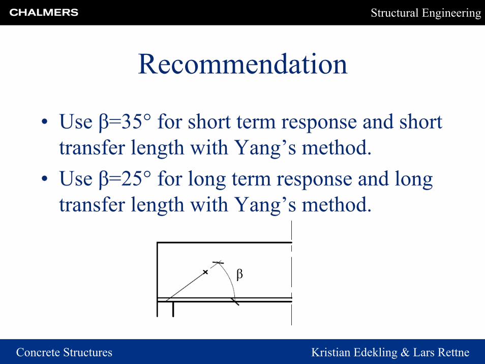
Recommendation
• Use β=35° for short term response and short transfer length with Yang’s method.
• Use β=25° for long term response and long transfer length with Yang’s method.
β

Structural Engineering
Concrete Structures Kristian Edekling & Lars Rettne
Thanks for your attention!