a parametric study of shear provisions for stiffened plate
TRANSCRIPT

University of Calgary
PRISM: University of Calgary's Digital Repository
Graduate Studies Legacy Theses
2000
A parametric study of shear provisions for stiffened
plate girders
Parthasarathi, N.
Parthasarathi, N. (2000). A parametric study of shear provisions for stiffened plate girders
(Unpublished master's thesis). University of Calgary, Calgary, AB. doi:10.11575/PRISM/24175
http://hdl.handle.net/1880/42697
master thesis
University of Calgary graduate students retain copyright ownership and moral rights for their
thesis. You may use this material in any way that is permitted by the Copyright Act or through
licensing that has been assigned to the document. For uses that are not allowable under
copyright legislation or licensing, you are required to seek permission.
Downloaded from PRISM: https://prism.ucalgary.ca
UNIVERSITY OF CALGARY
A Parametric Study of Shear Provisions for Stiffened Plate Girders
A THESIS
SUBMITTED TO THE FACULTY OF GRADUATE STUDEIS
IN PARTIAL FULFILMENT OF THE REQUIREMENTS FOR TFE
DEGREE OF MASTER OF ENGINEERING
DEPARTMENT OF C M L ENGINEERING
CALGARY, ALBERTA
APRIL 2000

National Library 1+1 dcmada Biblioth&que nationale du Canada
Acquisitions and Acquisitions et Bibliographic Services services bibliographiques 395 Wellington Street 395. rue Wellington Ottawa ON KIA ON4 OttawaON K1AON4 Canada Canada
The author has granted a non- L'auteur a accorde me Licence non exclusive licence allowing the exclusive pennettant a la National Library of Canada to Bibliotheque nationale du Canada de reproduce, loan, distribute or sell reproduire, preter, distri'buer ou copies of this thesis in microform, vendre des copies de cette these sous paper or electronic formats. la forme de microfiche/film, de
reproduction sur papier ou sur format ekctronique.
The author retains ownership of the L'auteur conserve la propriete du copyright in this thesis. Neither the droit d'auteur qui protege cette these. thesis nor substantial extracts fiom it Ni la these ni des extraits substantiels may be printed or otherwise de celleci ne doivent Stre imprimes reproduced without the author's ou autrement reproduits sans son permission. auton'sation_
ABSTRACT
Steel Design in Canada is based on CANICSA-S 16.1-94 "Limit States Design of
Steel Structures". The provisions in this Standard governing shear design of stiffened
plate girders, have to be combined with a number of other equations that influence the
choice of web thickness, girder depth, and the spacing of intermediate stiffenen.
This study reviews the influence of each of the equations that govern the shear
design of stiffened plate girders in order to determine the relevance of each equation. It
has been found that, of the twenty-six equations that could restrict the design, only five
are likely to have any influence on a typical design.
The mapping reveals that most equations have virmally no effect. This reveals
avenues for possible simplification of the standard. A design approach is suggested
which can be expected to lead to a choice of economical proportions with a minimum of
computational effort.

ACKNOWLEDGEMENTS
The investigation was directed by Rofessor RELoov, Department of Civil
engineering, The University of Calgary, Alberta, whose assistance, instruction, and
encouragement are gratefully acknowledged.
TABLE OF CONTENTS
Approval page ..................................................................
.......................................................................... Abstract
............................................................ Acknowledgements
Table of contents ...............................................................
.................................................................... List of tables
................................................................... List of figures
................................................................... List of symbols
PAGE
. * 11
... 111
iv
v
vii
... Vlll
CHAPTER OM: INTRODUCTION ...................................... 1
1.1 General .......................................................... 1
1.2 CSA Equations governing shear ............................. 1
1.3 Purpose and Scope ........................................... 5
CHAPTER TWO: REVIEW OF PREVIOUS WORK ............... 10
CHAPTER THREE: SHEAR DESIGN OF STIFFENED PLATE GIRDERS 23
3.1 G e e ...................................................... 23
................................................... 3 2 Anchor Panel 23
............................................ 3-3 Tension Field Panel 25
........................................ CHAPTER FOUR: CASE STUDIES 27
4.1 General ........................................................... 27
4.2 CaseStudies:PartI ........................................... 27
...... . 42.1 Discussion of the graphs (Fig 4 to Fig . 27) 40
PAGE
CHAPTER FOUR: CASE STUDIES (continued)
4.3 Case Studies :Part 2 ..........................................
.................... 4.4 Discussion on Graphs for Anchor Panel
............ 4.5 Discussion on Graphs for Tension Field Panel
................................................ 4.6 Optimum Depth
CHAPTER F I E : COMPARISON OF THE SHEAR DESIGN
PROVISIONS OF CSA S16.1-94 WITH OTHER
CODES OF PRACTICE ................................
5.1 C M S A S 16-1-94 Limit State Design of Steel Structures
........................ 5.2 AISC LRFD Vol.1 (Second Edition)
...................... 5.3 British Standard BS 5950-1990 Part 1
5 -4 Australian Standard AS 4 100- 1990 ..........................
5.5 Discussion on the Recommendations for Revisions to CSA
S 16.1094 for Shear Design ...................................
...................... CHAPTER SIX: SUA4MARY AND CONCLUSIONS
6.1 General ..............................................................
6.2 Conclusions .........................................................
6.3 Recommendations for Revisions to S 16.1-94.. ................
....................................................................... REFERENCES
................................................... APPENDIX A : Cost analysis

LIST OF TABLES
TABLE PAGE
S 1 6.1 -94 Equations .................................................... 7
Various Tension Field Theories for Plate Girders ................ 15
Shear Force Diagrams for Case Studies .................... ..., 29
Section properties of girders for Case Studies .................... 35
Anchor Panel Case Studies ........................................... 36
Tension Field Panel Case Studies .................................. 38
Comparison of Standards ............................... .. .... ... . 109
Comparison of 'hlw' limits ........................ .. ................ 110
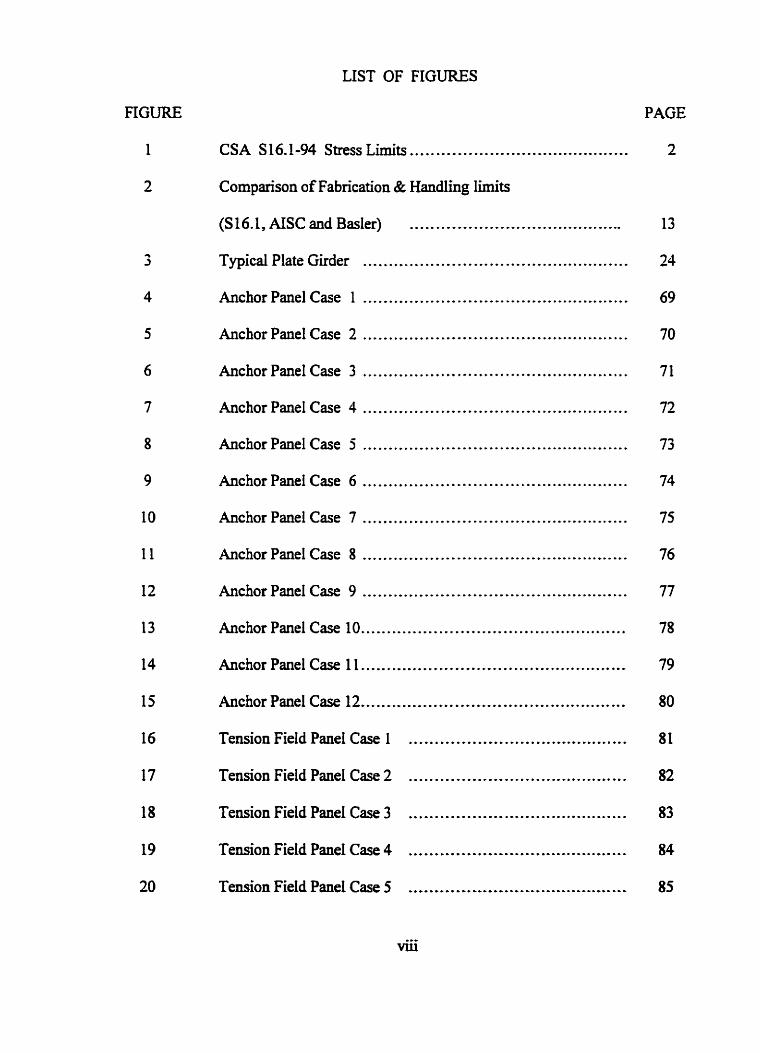
LIST OF FIGURES
FIGURE PAGE
CSA S16.1.94 Stress Limits .......................................... 2
Comparison of Fabrication & Handling limits
(S 16.1, AISC and Basler) .........................................
Typical Plate Girder ................................................... 24
Anchor Panel Case 1 .................................................. 69
Anchor Panel Case 2 ................................................... 70
Anchor Panel Case 3 ................................................... 71
Anchor Panel Case 4 ................................................... 72
Anchor Panel Case 5 ...................................................
Anchor Panel Case 6 ............................... ,. .................
Anchor Panel Case 7 ...................................................
Anchor Panel Case 8 ...................................................
Anchor Panel Case 9 ...................................................
Anchor Panel Case 10. ..................................................
Anchor Panel Case 1 1 ...................................................
Anchor Panel Case 12 ...................................................
Tension Field Panel Case 1 ..........................................
Tension Field Panel Case 2 ..........................................
Tension Field Panel Case 3 .......................................... 83
Tension Field Panel Case 4 .......................................... 84
Tension Field Panel Case 5 .......................................... 85

FIGURE
LIST OF FIGURES (contd.,)
PAGE
.......................................... Tension Field Panel Case 6 86
Tension Field Panel Case 7 ..................... .,, .................. 87
.......................................... Tension Field Panel Case 8 88
Tension Field Panel Case 9 .......................................... 89
.......................................... Tension Field Panel Case 10 90
TensionFieldPanelCase 1 1 .......................................... 91
.......................................... Tension Field Panel Case 12 92
Case Studies Part 2 : Example Problem ........................ 93
w VS. h for Anchor Panel .......................................... 94
a vs . h forAnchorPane1 .......................................... 95
w vs . h for Tension Field Panel ......I.......*....*.....g.**...* 96
................................. a vs . h for Tension Field Panel 97
Fs vs . hlw (ah= 0.5 ) .......................................... 1 1 1
Fs vs . WW ( & = l . S ) .......................................... 112
Fs vs . WW (ah = 2.5 ) .......................................... 113
Shear Buckling Coefficient k, ................................. 114
Comparison of maximum allowable 'hfw' limits based on
Flange (vertical) buckling and Fabrication & Handling Iimits
............... FVt =350 MPa (combined graph for aU codes) 115
LIST OF FIGURES (contd.,)
PAGE
Comparison of maximum allowable 'h/w' limits based on
Flange (vertical) buckling and Fabrication & Handling Limits
FYf =350 MPa ..........................................................
Comparison of mhmum allowable 'Ww' limits based on
Flange (vertical) buckling and Fabrication & Handling limits
Fyf =400 MPa ..........................................................
Comparison of m h m allowable 'h/w7 limits based on
Flange (vertical) buckling and Fabrication & Handling limits
Fyf = 450 MPa .........................................................

LIST OF SYMBOLS
a = centre-to-centre distance between transverse web stiffeners
Ar = flange area
AASHTO =American Association of State Highways a d Transportation Officials
AISC = American b t i ~ e of Steel Construction
AISI = American Iron and Steel Institute
AREA = American Railway Engineering Association
ASD = Allowable Stress Design
CISC = Canadian Institute of Steel Construction
CV = ratio buckling stress in shear I shear yield stress
A, =web area
E = elastic modulus of steel
F, = elastic critical plate-buckling stress in shear
F~ = inelastic critical plate-buckling stress in shear
FS = ultimate shear stress
Ft = tension-field post-buckling stress
Fy, Fp = specified minimum yield stress - web
Fyr = specified minimulll yield stress - flange
h = clear depth of web between fI anges
h7 = 'h' based on the line dividing elastic buckling and fabrication-handling zones
k,, k, = shear buckling coefficient for stiffened girder
kvu = shear buckling coefficient for unstiffened girder

Mu = factored moment (ASCE Code)
My = yield moment
OHBDC = Ontario Highway Bridge Design Code
q b = basic shear strength obtained f?om tables 22(a) to (d) in BS 5950: Part 1
q, = critical shear strength obtained fiom tables 2 1 (a) to (d) in BS 5950: Part 1
SSRC = Structural Stability Research Council
Vb = shear buckling resistance including tension field action
V, = shear buckling resistance excluding tension field action
Vr = shear force in a member or component under factored load
V,, = nominal shear strength
v, = factored shear resistance of a member or component
w = web thickness
w, = minimum 'wT based on the line dividing elastic buckling zone and fabrication-
handling zone
we = minimum 'w' based on elastic buckling of stiffened girder
wh = minimum 'w' based on fabrication and handling
wi = minimum 'w' based on inelastic buckling of stiffened girder
w, = minimum 'w' based on yield stress limit
w, = minimum 'w' for unsfiffened girder based on elastic stress limit
we = 'w' based on the dividing line between elastic and ineIastic stress zones
wh = injnimuxn 'w' for uastiffened girder based on inelastic stress limit
W V ~ = minimum 'w' to avoid vertical buckling of compression flange
w e = minimum web thickness
9 = resistance factor
0, = residual stress
o, = yield stress
CHAPTER ONE
INTRODUCTION
1.1 General
In the shear design of plate girders, it is assumed that the web is plane and the
material is elasto-plastic. The web buckles at a stress that can be calculated fiom the
theory of plate buckling. The allowable shear on the girder at this stage is based on beam
action of the girder. After buckling of the web, the stress distribution in the web changes
and additional post buckling strength is mobilized. The load is resisted by a Pratt truss
formed by the web in diagonal tension, the stiffeners as vertical compression members
and the flanges as top and bottom chords (Basler, 1963). The mechanism by which the
buckled web resists the loads is called "Tension-field action". The transversely stiffened
plate girder can carry two or three times the load initiating web budding before collapse
(McCormac, 1 992).
1.2 CSA Stress Limits and Equations Governing: shear
The CISC commentary on the stress Iimits and the CSA S16.1-94 shear design equations
have been reproduced here for refance.

WEB SLENDrnNESS, hlw
Fig. 1 CSA S 16.1-94 Stress Limits
CISC Commentary

13.4 Shear 13.4.1 Wds of fltxutai Members with Two Pknges I3.4.1.l Ehadc Analysis Except as noted in C b e 13.4.1.2, the factored shear resistance, 5 , dweloped by
the web of aflemrunl member shall be toRen as
V r = / A w F , where A, = shear urea (&for rolled shapes and hw fir girders); and F, P as follows:
(b ) 419 W
F, = (O.SF, - 0.866 F,) {,,A}
F, (05 Fv - 0.866 F,) {d-} where k, = shear buckling coqftcient
k,= 4 + 5.34 when a / h < f
(a /h )2
k" = 5.34 + 4 when a / h 2 I
(alh)' a / h = aspect ratio, the ratio of the dbtance between st$eners to web depth
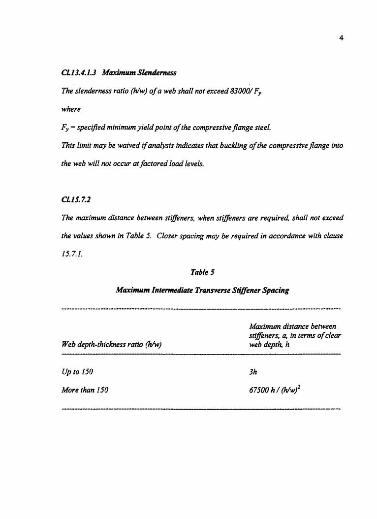
CLI3.4,1,3 Marrtrnum Slenderness
The slenderness ratio F/w) of a web shall not exceed 83000/ Fy
where
Fy = specified minimum yield poi^ of the compressive fIange steel.
This limit may be waived ifanalysis indicates that buckling of the compressivejknge into
the web will not occur at factored load levels.
CLIS. 7.2
The maximum distance between stifjeners, when stiijeners me required shall not exceed
the values shown in Table 5. Closer spacing may be required in accordance with clause
15-7.1.
Table 5
M(~~~*rnurn lntemtedioe Transverse Shiner Spacing
Web depth-rhichess rario 0
M m * m distance between stifenem, a, in t e r n of clear web deprh, h
- - - --p--pp-------p-p-p---------pp--p--p-p---------
Up to 150 3h
More than 150 67500 h / ww)'

5
1.3 Pmose and S c o ~ e
The geometric parameters that determine the shear buckling strength of plate
girder webs are:
Girder depth/web thickness 'h/wY
Spacing of intermediate transverse stiffenedgirder depth 'ah'
There are 12 equations given in CAN/CSA-S16.1-94, which govern the shear design of
plate girders. These equations can be combined with each other to produce 26 design
check conditions as given in the Table 1. Essentially, it is required to find a combination
of web thickness, girder depth and stiffener spacing that will be economical in material
and for fabrication. The shear design using the 26 design check conditions is a very
tedious and time consuming exercise. Even when the design is carried out using these
equations, it is unclear to the designers as to the stress levels achieved, available safety
margins and the interaction between various design parameters.
This dissertation presents a detailed study of the equations for shear in S 16.1-94
for the foUowing :
- Examining their validity and inauence in practical cases
- Developing design diagrams for various shear zones
- Studying the influence and interaction of the design parameters (web thickness
'wY, girder depth 'h' and the spacing of intermediate stiffener 'a').
- Comparing the design procedure of S16.1-94 with the procedures adopted by
the codes of practice of other countries.
6
- Simplifying the shear design by suggesting modification to the existing
equations and recommendations for eliminating some equations which do not
inauence the design.
The study of the equations is included for stiffened plate girders only. The unstiffened
plate girder shear design is excluded h m this study.

7 Table 1 : S 16.1-94 Equations
No. Equation Description S-16.1 C1.
Vf Minimum 'w' based on the I3.4.l.la [I] wv= 0.66 / h F, yield stress limit.
- F,/h Minimum 'w' to avoid vertical 13 -4.1.3 PI wvb - buckling of compression
flange. Minimum 'w' based on yield 13.4.1. la
0.66 9 F, 83 000 stress and vertical buckling and
13.4-1.3 Minimum 'w' for unstiffened girderbasedoninetasticstress 13.4.l.lb limit
u3 Minimum'w'forunstiffened 13.4.1,Id girder based on elastic stress
180 000 4 k,, limit.
180 000 V, Line dividing the elastic and 13.4.1- 1 b, 161 Wie= 2902 / h F, ineiastic stress zones 13.4.1, ld
Y4 Line dividing elastic buckling 13.4.1.1 d m h, = [~TJOO) zone and fkbrication-handling and
180000/kv (a lh) zone 15.7.2
Minimum 'w' based on 13.4.1. lb 181 inelastic buckling of stiffened
girder U3
vf" Minimum 'w' based on elastic 13.4.1, I d
[91 we =[ ) buckling of stiffened girder 180 000 1 k,
Minimum 'w' based on 15.7.2
67 500 fabrication-handIing
[ll] a = 3 h Miaxhum stiffener spacing 'a' 15.7.2 u3 Mimimum 'a' based on 13.4.1.ld
[I2] a = 6 7 5 0 0 [ ~ [ vf ,'I fabrication-handling limits and and h 180000# k,, elastic buckling 157.2
'a' based on Wrication- 13.4.1.3 [13] a=67500h handling and v e m d buckling and
15-72
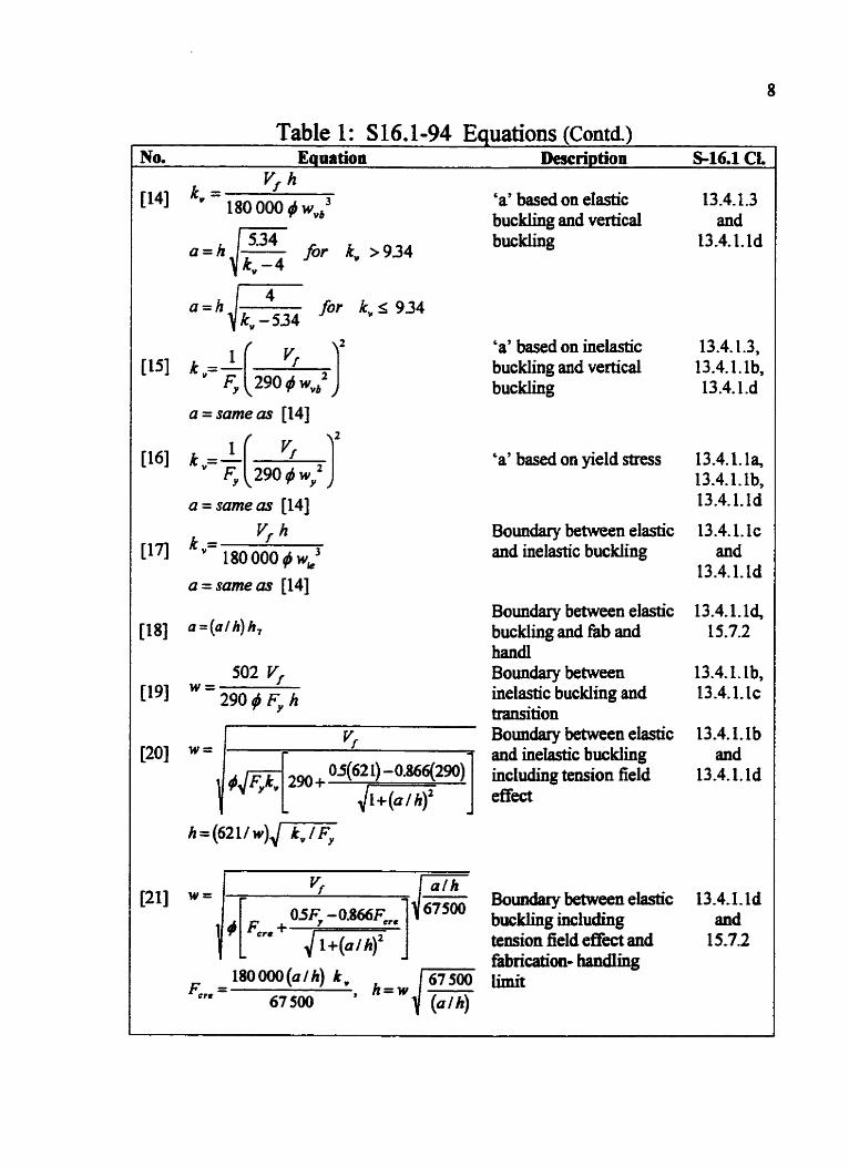
Table 1 : S 16.1-94 Equations (Contd.) Nom Equation Description S-16,l CL
T
vf
[I4] ' V = 180 000 4 w,' 'a' based on elastic 13-4-1.3 buckling and vertical and
==h,/= itv ,934 buckling 13.4.1. ld k, -4
4 for k , s 934
k" -534
'a' based on inelastic 13.4.1.3, buckling and vertical 13.4.I.lb, buckling 13.4.l.d
a = same as [14]
'a' based on yield stress 13.4.1.1 a, 13.4.1.lb, 13.4.1. Id
Boundary between elastic 13.4.1. 1 c and inelastic buckling and
13.4.1. Id
Boundary between elastic 1 3 -4.1.14 [18] a=(afh)h7 buckling and fab and 15.7.2
hand1 502 Vf Boundary bemeen 13.4.1.1b,
[19] W = 290 / F,, h inelastic buckling and 13.4.1. lc transition Boundary between elastic 13.4.1.1 b and inelastic buckling and hc1udi.g tension field 13.4.1. ld &kct
Bomdarybetweenelastic 13.4.I.ld buckling including and tension field effkct and 15-7.2 fabniwioa- handIing
67500 F, , = 67 500

Table 1 : S 16.1-94 Equations (Contd.) No. Equation Description S16.1
CL [221 w = (h I 5 0 2 ) J m Minimum 'w' for 'ah' 13.4,l.lb
based on inelastic stress
Minimum 'w' for 'ah' based on 13.4.1.1~ inelastic buckling including tension field effect
I J
Minimum 'w' for 'ah' based on elastic 13.4.1.1 d buckling with tension field effect
05 F, - 0.866 F,,, and elastic buckling 15.7.2 ere+ d-. ) including tension field
I + ( a ~ h ) ~ effkct
[251 h =
Maximum ' h' based 13.4-1, Id on vertical buckling and
0.5 F,, -0.866 F, and inelastic buckling 13.4.1.3
J- including tension field effect
83 000 Y, Maximum 'h' based 13 -4-1.1 d f , on vertical buckling and
CHAPTER Two
REVIEW OF PREVIOUS WORK
2.1 General
Ever since plate girders came into use, it has been recognized that beam action done is
not the only way that shear can be carried. Extensive discussion of the problem of web
Hen ing was camed on just before the end of the nineteenth century. Model studies and
girder tests carried out during that time clearly indicated the importance of the web as a
tension element and the stiffeners as compression elements. In 1916, Rode wrote a
dissertation in which one chapter dedt with the webs of plate girders. He may have been
the first to mathematically formulate the effect of tension field or truss action which sets
in after the web loses its rigidity due to buckling. He proposed to evaluate its influence
by considering a tension diagonal of a width equal to 80 times the web thickness. With
the development of aeronautical science, the shear canying capacity of membrane-like
structures became vital and the tension field theory started gaining importance further.
To understand the behavior of Mened plate girders and to formulate design criteria,
Konrad Basler and Bruno Thiirlimann conducted extensive investigations of welded plate
girders at the Fritz Engineering Laboratory at Lehigh University &om 1955 to 1963.
They were the first to successfully formulate a model for the plate girders of the type
used in civil engineering structures.

11
2.2 "Streneth of Plate Girders in shear." and "Strength of Plate Girders Under
Combined Bending and Shear." Transaction ASCE, Vo1.f 28, Part 11. D-683 - 735 by
K.Basler, (1 963a.b)
Based on numerous studies, testing and investigations, Basler established the
following:
The ultimate shear force was expressed in a formula, which was a hct ion of the
girder depth, web thickness, the stiffener spacing and the material properties Fy and E.
Ultimate shear force was adopted as ' ~ ~ / d 3 ' fiom von Mises' yield condition for plane
stresses. The tension field strip width was assumed to be a Little wider than half the
girder depth and its inclination was assumed to be between 45' and 0' based on 'ah'
values fiom 0 to ao . The tension field strip inclination was less than the inclination of
the panel diagonal. The ultimate shear force was the sum of shear capacity due to beam
action and the shear capacity due to tension field action. When the stress exceeded the
shear yield stress value, the tension field effect was no longer considered.
The influence of strain hardening was based on the experimental work of Lyse and
Godky (1935), which covered the range of web depth-to-thickness ratios from 50 to 70.
The experimentally obtained ultimate shear force exceeded the plastic shear force in al l
cases. It became apparmt that the conventional procedure was too conservative. Since
the local strain hardening must be preceded by shear yielding, the shear resistance
capacity of the web was not to be augmented by the development of the tension field after
shear yielding.
Basler suggested that in the range of high web slenderness ratios, the stiffener spacing
&odd not be arbitrarily large. Mthough the web might still be sufficient to carry the
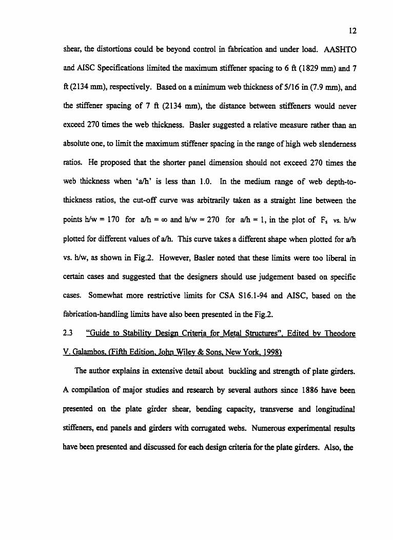
12
shear, the distortions could be beyond control in fabrication and under load. AASHTO
and AISC Spec5cations limited the maximum stiffener spacing to 6 A (1829 mm) and 7
ft (2 134 mm), respectively. Based on a minimum web thickness of 5/16 in (7.9 mm), and
the stif3ener spacing of 7 A (2134 mm), the distance between stiffeners would never
exceed 270 times the web thickness. Basler suggested a relative measure rather than an
absolute one, to limit the maximum stiffener spacing in the range of high web slenderness
ratios. He proposed that the shorter panel dimension should not exceed 270 times the
web thickness when 'ah' is less than 1.0. In the medium range of web depth-to-
thickness ratios, the cut-off curve was arbitrarily taken as a straight line between the
points h/w = 170 for ah = and h/w = 270 for ah = 1, in the plot of Fs VS. h/w
plotted for different values of ah. This curve takes a different shape when plotted for ah
vs. Ww, as shown in Figl. However, Basler noted that these limits were too liberal in
certain cases and suggested that the designers should use judgement based on specific
cases. Somewhat more restrictive limits for CSA S16.1-94 and AISC, based on the
fabrication-handling limits have also been presented in the Fig.2.
2.3 "Guide to Stabilitv Design Criteria for Metal Structuresn. Edited bv Theodore
V. Mambos. Rifth Edition. John Wdey & Sons, New York. 1998)
The author explains in extensive detail about buckling and strength of plate girders.
A compilation of major studies and research by several authors since I886 have been
presented on the plate girder shear, bending capacity, tramverse and longitudinal
stiffeners, end panels and girders with corrugated webs. Numerous experimental d t s
have been presented and discussed for each design criteria for the plate girders. Also, the

Web Slenderness Ratio, hEw
Fig. 2 Comparison of Fabrication & Handling Limits (S 16.1, AISC and Basler)

14
design criteria for web buckling in AASHTO and AREA have been discussed. A plate
girder, even without transverse stiffeners, can develop a shear stress at the ultimate load
that is several times the shear-buckling stress due to the tension field action.
With continued increase in load, the tensiIe membrane stress in the web combined
with the shear buckling stress causes yielding of the web and failure of the panel occurs
upon formation of a mechanism involving a yielded zone in the web and plastic hinges in
the flange. The additional shear associated with the formation of a failure mechanism
involving plastic hinges in the flanges is called ''&me action". Wagner (193 1) used a
complete uniform tension field, assuming rigid flanges and a very thin web. There were
no plastic hinges, since the flanges were asmmed infinitely stiff. Wagner's analysis was
found to be satisfactory for aircraft structures. Basler and Thiirlimann (1963) were the
first to successfdly formulate a model for plate girders of the type used in civil
engineering structures. They assumed that the flanges are too flexible to support a lateral
loading from the tension field, and used the diagonal yield band in the web to determine
the shear strength. The inclination and width of the yield band are defined by the angle 0,
which is chosen so as to maximize the shear strength. It was first shown by Gaylord
(1963) and later by Fujii (1968) and Selberg (1973) that Basler's fonnula gives the shear
strength for a complete tension field instead of the limited baud.
Many variations of the post buckling tension field have been developed since the
Basler-Thiirlkmn solution was published. These studies are presented in Table 2, which
shows different patterns of tension field, the positions of the plastic hinges if involved in
the solution, and the edge conditions assumed in computing shear buckling stress.

Table 2
Various Tension Field Theories for Plate Girders ( from SSRC )
Shear and Moment
1
Yes
I
No
Yes
No
I
Yts
Yes
Yes
1
YCS
No
1
Yes
Longitudinal Stiffener
yts* Cooper (1965)
No
Yes
Yes, at middepth
Yes
Yes
No
Y e
No
Yes
b
Investigator Mecharram Web Buckling Unequal Edge Support Ranges
(1963-a)
I
9 =I
(1964 Yes
. FuiiS
(1968,3971)
(1971)
OIbpnko (1969)
t <
et rl. (1975)
Web Y e , in (1974-a, b)
C
Cbrk No (1971)
1
Steinhardt and Schroter (1971)
4 C2 I-
F NO

In most cases, the shear buckling strength is added to the vertical component of the
tension field to give the contribution of the web to the shear strength of the girder panel.
The formulae developed by Basler (1963), Hoglund (1973) and Herzog (1974) were
simple compared to others which were very complicated
When considering the bending strength of plate girders, the buckling of the
compression flange into the web (vertical buckling) was observed in many tests. Basler
and T h ~ h a n n (1963) developed the following equation, which Iimited the 'h/w' value.
But the experiments showed that vertical buckling occurred only after general
yielding of the compression flange in the panel and hence the above equation may be
very conservative. However, the above limit is still adopted in AISC to facilitate
fabrication and to avoid fatigue cracking under repeated loads. Basler proposed the
following equation, which reduces the moment of resistance due to slender webs.
The tension field in a plate girder pane1 is resisted by the flanges and by the
adjacent panels and tramverse Menen. As there is no continuity, the end panels are
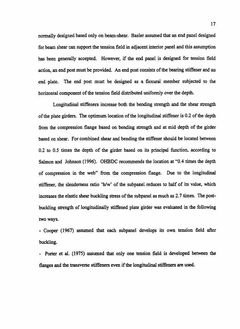
17
n o d y designed based only on beam-shear. B a s k assumed that an end panel designed
for beam shear can support the tension field in adjacent interior panel and this assumption
has been generally accepted. However, if the end panel is designed for tension field
action, an end post must be provided. An end post consists of the bearing Mener and an
end plate. The end post must be designed as a flexural member subjected to the
horkontd component of the tension field distniuted uniformly over the depth.
Longitudinal stiffeners increase both the bending strength and the shear strength
of the plate girders. The optimum location of the longitudinal stiffener is 0.2 of the depth
from the compression flange based on bending strength and at mid depth of the girder
based on shear. For combined shear and bending the stiffener should be located between
0.2 to 0.5 times the depth of the girder based on its principal function, according to
Salmon and Johnson (1 996). OHBDC recommends the location at "0.4 times the depth
of compression in the web" fiom the compression flange. Due to the longitudinal
stiffener, the slenderness ratio 'hhv' of the subpanel reduces to half of its value, which
increases the eiastic shear buckling stress of the subpanel as much as 2.7 times. The post-
buckIing strength of I o n g i t u W y stiffened plate girder was evaluated in the following
two ways.
- Cooper (1967) assumed that each subpanel develops its own tension field after
buckling.
- Porter et d. (1975) assumed that only one tension field is developed between the
flanges and the transverse stiffeners even if the IongitudinaI stiffeners are used.

18
The tension field shear resistance was calculated based on the critical beam-action
shear corresponding to buckling of the largest subpanel. Of many theories and analyses,
Cooper's theory is the most conservative and easy to use.
2.4 4 4 b ~ r o v e d shear strength of webs designed in accordance with the LRFD
mecification" bv Mark Andrew Bradford. Universitv of New South Wales, Australia,
AISC Engineering Journal, Third Ouarter 1996, Vo1.33. No.3
The dependence of the LRFD design rules for shear resistance of the web, using an
elastic local buckling coefficient is discussed in this paper. A finite strip method of
analysis that incorporates shear, is used to derive the elastic local buckling coefficients
that incorporate the reshz.int provided by the flanges of an I-section member. It is shown
by an example how the buckling coefficients are enhanced. However, this study excludes
the tension field effect completely although intermediate stiffeners are assumed in the
design. The finite strip method used in this paper differs from the finite element method
by the way that the member is subdivided into longitudinal strips. The longitudinal
variation of displacements is represented by harmonic firnctions. In the finite element
method, the strips would be Funher subdivided into rectangular elements whose
displacements are represented by polynomials.
Doubly symmetric I-beams were studied under pure shear for a wide range of
geometric properties of the section. In aIl cases, 'h/w' = 200 was adopted, which did not
affect the values of 'k,'. I-beams with various flange widths, flange thicknesses, web
depths, web thicknesses and M e n e r spacing were studied The buckling coefficient
'1' vs. stitfener spacing was plotted for various combinations of flange tbickness/web
thickness and flange widthfweb depth cases. The study indicated that the values of 'kr '
19
are enhaaced due to the increased stockiness of the flange relative to the web. These
local buckhg coefficients were greater than that of the LRFD specification, which
increase the shear resistance of I-beam.
2.5 '?)esim of Modem Highway Bridges" bv Narendra Taly. PhD., P.E. Devt
Civil Engineering California State University. Los Anaeles. (The McGraw Hill
Cornmmies hc.. 1998).
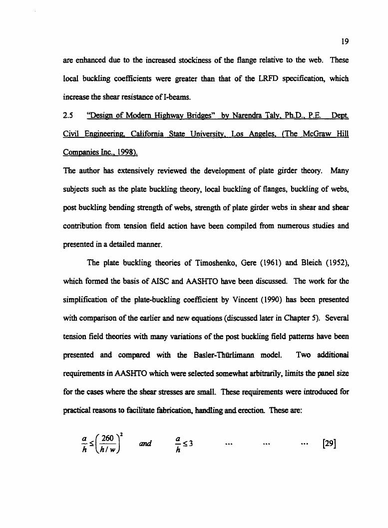
The author bas extensively reviewed the development of plate girder theory. Many
subjects such as the plate buckling theory, local buckling of flanges, buckling of webs,
post buckling bending strength of webs, strength of plate girder webs in shear and shear
contribution from tension field action have been compiled from numerous studies and
presented in a detailed manner.
The plate buckfing theories of Timoshenko, Gexe (1961) and Bleich (1952),
which fonned the basis of AISC and A A W O have been discussed The work for the
simplification of the plate-buckling coefficient by Vincent (1990) has been presented
with comparison of the earlier and new equations (discussed later in Chapter 5). Several
tension field theories with many &ations of the post b u c h g field patterns have been
presented and compared with the Basler-Thtklimann model. Two additional
requirements in AASHTO which were selected somewhat arbitrarily, b i t s the panel size
for the cases where the shear stresses are d. These requirements were introduced for
practical reasons to facilitate fabrication, haadling and erection, These are:

2.6 "Steel Structures - Design and behavior". bv Charles G. Salmon and John E-
Johnson. Fourth Editioa Hamr C o b s College - Publishers. 1996)
The theory of plate girder design is presented in a simple form, covering a l l
aspects of design such as the bending strength, shear strength, stiffeners and tension field
theory. It starts with defining the difference between a beam and plate girder based on
compact, non-compact and slender members. The derivations of equations are presented
based on Basler's work, for the following:
- Vertical flange buckling.
- Maximum 'Ww' for moment strength and moment strength reduction.
- Elastic and inelastic web buckling under pure shear.
- Shear and tension field capacity
- LRDF and ASD equations of AISC
The discussion on both LRFD and ASD equations provides a clear understanding
of the differences between the two design methods. The requirements for omitting the
stiffeners have been reviewed. Optimum girder depth and flange area formulas are
derived fiom basics. Several example problems have been solved at the end of the
chapter.
2.7 " S t r u d Steel Desiw LRFD Method". by Jack C. M C C O ~ . (Hamer & Row
Publishers. New York. I9921
Plate girder design is discussed briefly with examples. The advantages of a plate
girder over a steel truss have been reviewed. The plate girder is distinguished clearly
fkom a beam section, based on web buckiing. The tmwerseIy stiffened plate girder can

21
cany two or three times the load initiating web buckling before collapse. Limits for
proportioning of plate girder dimensions are:
- 1/10 to 1/12 of span, depending on the loading.
- Fabrication and transportation constraints (headroom clearances on highways) may
limit the girder depth to a maximum of 10 to 12 feet (3.0 m to 3.7 m).
There is a brief discussion on tension field theory and web buckling. Example
problems have been solved to provide a clear understanding of the assumptions and the
theory.
2.8 "Structural Steel Design, LRFD Approach" by J.C, Smith. (Second Edition. John
Wilev & sons. Inc.. New York. 19961
Plate girder design in accordance with the AISC LRFD method has been
discussed in detail with numerous examples. The basic difference between a beam and
plate girder, criteria for intermediate stiffeners and tension field theory have been
discussed in general. The guidelines for economical girder depth are 1/15 to 118 of span.
Simple spans of 70 to 150 A (21 m to 46 m) are typical for plate girders in buildings and
highway bridges. For longer continuous spans of 90 to 400 ft (27 m to 122 m), the
section depth varies from a maximum at the support to a minimum at mid span
The advantages of a built-up plate girder as compared to a truss are:
- Fewer field erection problems, but a larger crane may be required.
- Fewer critical points in the member at which the design requirements may govern.

The tension field design method is not applicable for:
- Tapered web girder
- Hybrid girder
- Anchor p e l
- Any panel for which :
CHAPTER THREE
S H E A R DESIGN OF STIFFENED PLATE GIRDERS
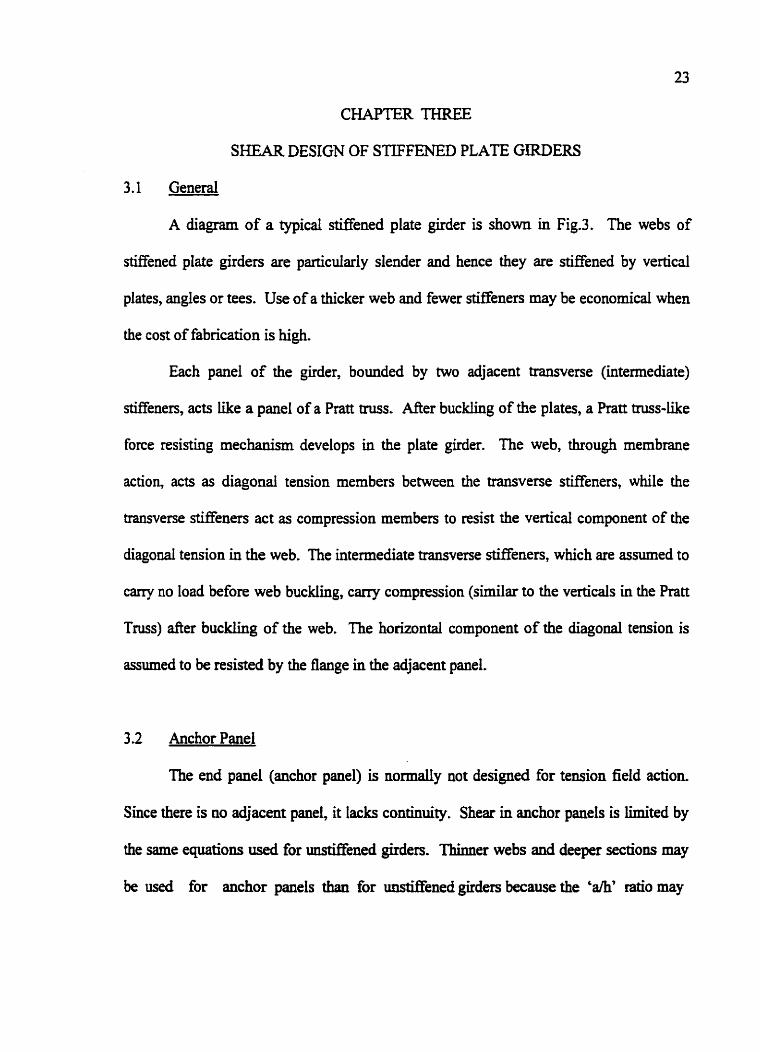
3.1 General
A diagram of a typical stiffened plate girder is shown in Fig.3. The webs of
stiffened plate girders are particularly slender and hence they are stiffened by vertical
plates, angles or tees. Use of a thicker web and fewer stiffeners may be economical when
the cost of fabrication is high.
Each panel of the girder, bounded by two adjacent transverse (intermediate)
stiffeners, acts like a panel of a Pratt truss. Mer buckling of the plates, a Pratt truss-Like
force resisting mechanism develops in the plate girder. The web, through membrane
action, acts as diagonal tension members between the transverse stiffeners, while the
transverse stiffeners act as compression members to resist the vertical component of the
diagonal tension in the web. The intermediate transverse &eners, which are assumed to
carry no load before web buckling, carry compression (similar to the verticals in the Ratt
Truss) afker buckling of the web. The horizontal component of the diagonal tension is
assumed to be resisted by the flange in the adjacent panel.
3.2 Anchor Panel
The end panel (anchor panel) is normally not designed for tension field action
Since there is no adjacent panel, it lacks continuity. Sheat in anchor panels is limited by
the same equations used for mstiffened girders. Thinner webs and deeper sections may
be used for anchor panels thaa for unstiffened girders because the 'am' ratio may

TENSION FIELD ACTION NOT PERMlllEO
INTERMEDIATE STIFFENERS
CROSS SECTION
Fig. 3 Typical Plate Girder
ANCHOR I PAWEL
INTERMEDIATE STIFFENERS
25
be chosen so that the plate buckling coefficient k, is greater than the 5.34 that is used for
mstBened girders. The maximum anchor panel length for a chosen web thickness and
depth is determined based on the limits imposed by inelastic buckling, elastic buckling
and the two Iimits on 'ah' fiom C1.15 -7.2. Values of 'ah' approaching 3.0 produce little
benefit and hence are unlikely to be used for anchor panels. The appropriate ah ratio for
anchor panels will generally be less than one.
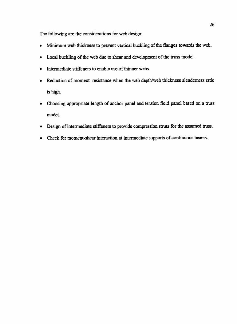
3.3 Tension Field Panel
The shear in the first tension field panel will be based on the shear force at the
first intermediate stiffener and hence, will be slightly lower than for the anchor panel.
Tension field panels can have larger 41 ratios than anchor panels because of the
additional strength provided by the tension field. The rninhum web thickness, minimum
depth and maximum depth based on vertical web buckling of tension field panels are the
same as for anchor panels.
Tension field action increases the shear strength in part of the inelastic buckling
zone as well as the entire elastic buckling range. The inelastic buckling zone is very
small and hence the modified inelastic buckling equation (to include tension field effect)
is generally of Iittle interest. The modified elastic buckling equation will permit thin
shallow webs, which may not be economical due to the requirement of large number of
stiffieners. The equation likely to limit the maximum 'ah' of tension panels is the
equation from C1.15.71, which is empirical and based on practical considerations of
fabrication and
26
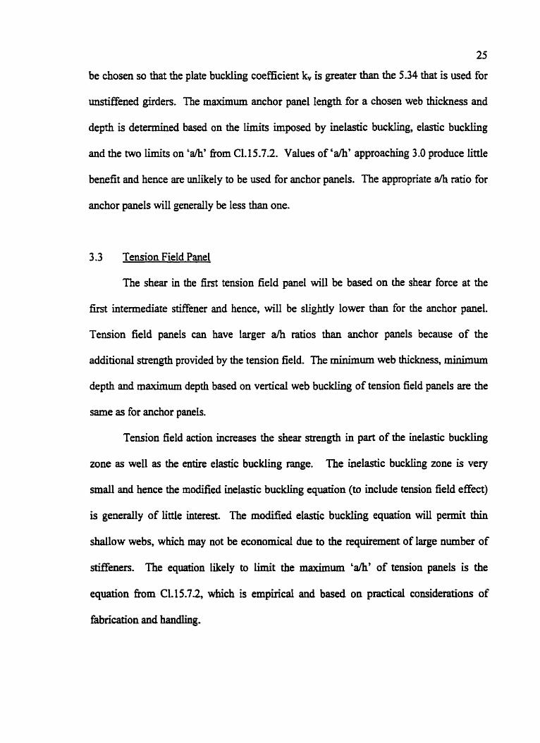
The following are the considerations for web design:
Minimum web thickness to prevent vertical buckling of the flanges towards the web.
Local buckling of the web due to shear and development of the truss model.
Intermediate stiffeners to enable use of thinner webs.
Reduction of moment resistance when the web depthhveb thickness slenderness ratio
is high.
Choosing appropriate length of anchor panel and tension field panel based on a
model.
Design of intermediate stiffeners to provide compression struts for the assumed truss.
Check for moment-shear interaction at intermediate supports of continuous beams.

CHAPTER FOUR
CASE STUDIES
4.1 General
The following are the case studies considered:
- Practical cases chosen from previously engineered and built structures.
- Example problems fiom various structural steel design textbooks.
S 16.1-94 provisions for the shear design of plate girders involve 12 eqyations, which
produce 26 design check conditions as per Table 1. A Mathcad computer program was
developed that took into consideration ail the design check conditions. The program
included commonly used web thiclmesses and provisions for varying the stiffener spacing
(a), yield stress of flange and web material. Two computer programs were developed
for the following:
- Anchor panel
- Tension field panel
4.2 Case Studies: Part 1
Twenty-four case studies (12 anchor panels + 12 tension field panels) which have
been considered in this report are presented in the Tables 3 to 6. Each case study was
analyzed using the computer program to examine the validity and influence of each
e@on given in S16.1-94. The details of the girders, corresponding shear force
diagrams and the sectional properties used for the case stucfies are presented in Tables 3

28
and 4. Tables 5 and 6 List a l l the geometric parameters assumed in the design, fmored
shear force and the source of the case study. The last column of Tables 5 and 6 shows the
governing equation for each case. The program results have been presented in a
graphical form that shows the foUowing:
- Upper and lower limits for the selection of the design parameters viz web thickness
(w), web depth (h) and the spacing of the intermediate stiffer~ers (a).
- The interadon between the design parameters.
- The influence of each S 16-1-94 equation.
The anchor panel case studies have been presented in Fig. 4 to Fig. IS and the tension
field case studies in Fig. 16 to Fig 27. A cost study for specific cases, where economy
could be achieved, has been presented in Appendix A.
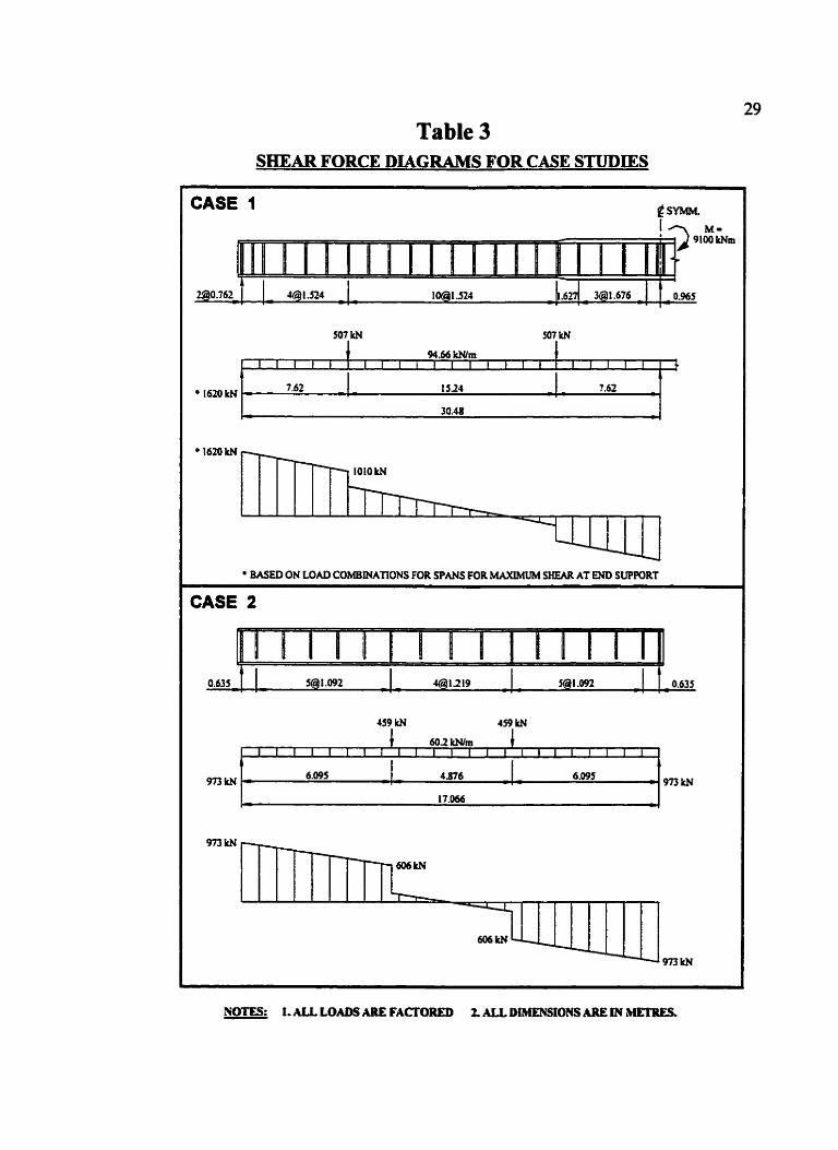
Table 3 SHEAR FORCE DIAGRAMS FOR CASE STUDIES
NOm I, ALL LOADS ARE FACTORED 2. ALL DtblENSIONS ARE IN C E T R E S
7.62
a
CASE 1
507 W 507 W
94.66 W m
l " " ' i i i ' ~ i " ~ l " i l i l " , ~ 1620 W
30.48
I620 kN
BASED ON LOAD COMBINA'I1ONS FOR SPANS FOR MAXIMUM SHEAR AT END SUPPORT
CASE 2
. . . .
459 kN 459 kN
9nkN
I
IS24 . - 7.62
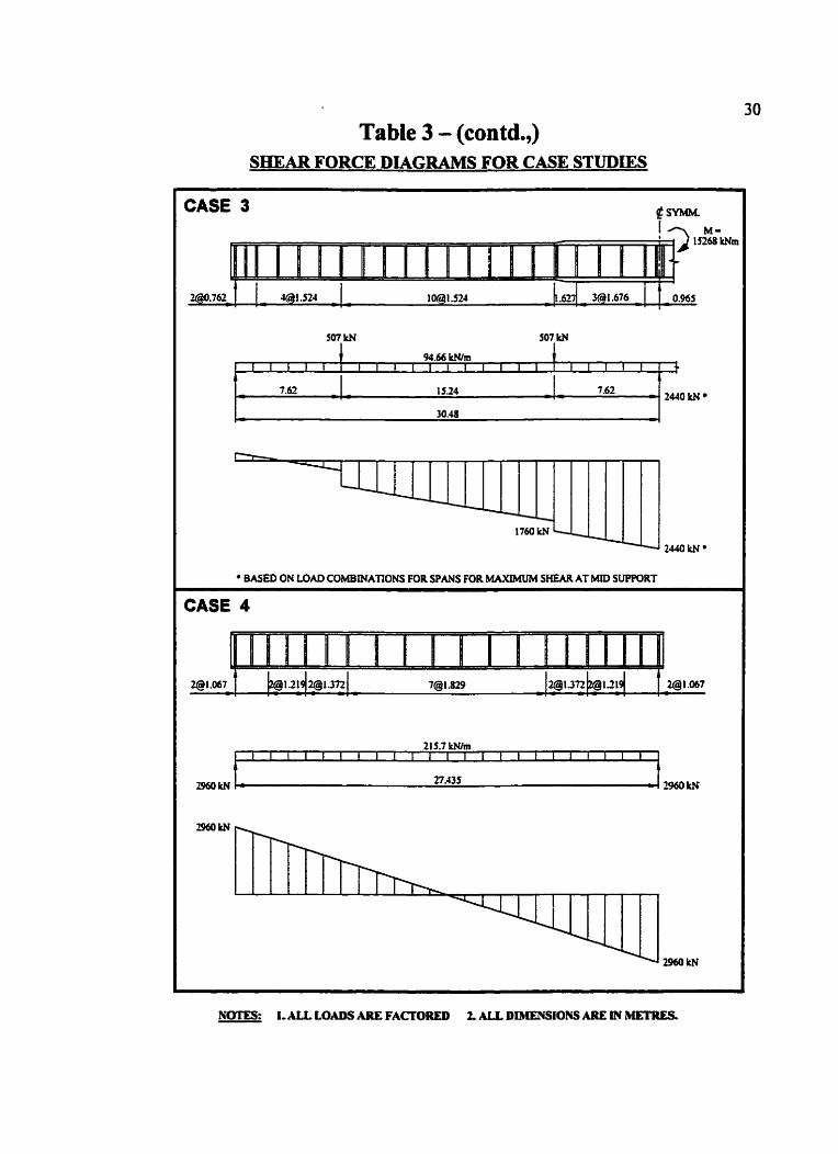
Table 3 - (contd.,) SHEAR FORCE DIAGRAMS FOR CASE STUDIES
CASE 3
507 kt4
94.66 W m 1 1 1 1 1 1 1 1 L I I I I I I I I I I I I I ~
7.62 IS24 7.52 r: I 2440 kN
- 1760W 1
2440 IcN
BASED ON LOAD COMBINATIONS FOR SPANS FOR MAXIMUM SHEAR AT MID SUPPORT I
CASE 4
215.7 W m I I I I ~ I ~ I ~ I ~ I I I ~ I ~ I I I ~ ~ I
27.535
NOTES: I-ALL LO- NE FACTORED 2. ALL, DIhLENSIONS ARE IN METRES,
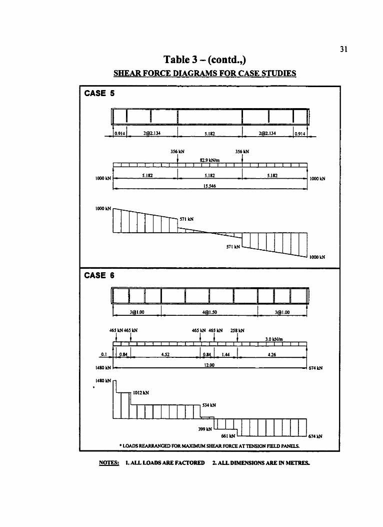
Table 3 - (contd.,) SHEAR FORCE DIAGRAMS FOR CASE STUDIES
NOITS. I, ALL LOADS ARE FAmORED 2. M L DIhENStONS ARE M bETRES -
h
CASE 5
356 W 356 kN
1 82-9 Wlm 1 1 I I L 1 1 '
I
I I I I I I L I I
t I l I I I
1oookN 5.182 -= 5.182 5.182
15546 w
looow
loo0 kN
loo0 W
CASE 6
465 kN465 kN 465 W 465 kN 258 W
3.0 klWm l i l l l l l f l l
II
432
1480W J- I 2.00 674 kN
1480 kN s
I I 661LNl - 674 kN . L O M S REARRANGED FOR MAXlMUM SHEARrnRcE ATTPISfON FrELD P-.
I

Table 3 - (contd.,) SHEAR FORCE DIAGRAMS FOR CASE STUDIES
NfFIES: 1 . U LOADS ARE FACTORED f 1SW. DUKE.SSIONS ARE IN MlXREk -
CASE 7
987 1tN 987 W 987 W 987 kN
1780 ItN
3110kN
2122 W
1 1 1 1 1 . . 1131 kN
117W
8-70 kN 1324 kN
r
1770 kNL 1780 kN
' LOADS W G E D FOR MAXIMUM SHUR FORCE AT TENSION FIELD PANELS.
CASE 8
1067kN 1067 W
42.1 Whn
1413 kN
I I I ~ I I I I I I I I L B ~ I I I I I I I ,
. - 5.487 5.m 1 5.48f - 1413 W 16.46 1
: - 4
1413 kU I taw
I15 W
lta2ttN* - , - * 1413kN

Table 3 - (contd.,) S H E A R FORCE DIAGRAMS FOR CASE STUDIES
CASE 9
3200 W
I
2123 W 2603 ku
2123 kN
- I245 kN
195JltNd
2603 W I I
CASE 10
987 W 987 W
1674 kN
mow7
IBS8 lrN
1 1 1 1 l 1 1 1 l 8)5W
r
- 1674 kN
LOADS REARRANGED FOR MAXIMUM SHEARFURCE ATTENSION FIELD PANEU-
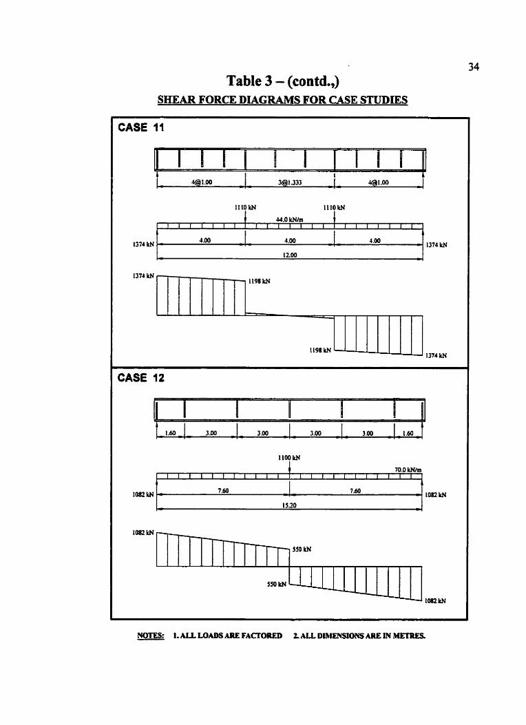
Table 3 - (contd.,) SHEAR FORCE DLAGRAMS FOR CASE STUDIES
NOTES: 1. ALL LOADS M E FACTORED 2. ALL DIMENSIONS ARE JN METRES
CASE I 1
1110k.N lltOkN
44.0 W m I I I I I I I I I I I l I I '
4.00 4.00 I374 ltN
4.00 - - - 1 2.00
r - 4
1374 W
I374 W - 1 198 W
1 . -
1198 W - 1374 kN
CASE 12
1100 kN
70.0 W m
I
1mw
1082 W
+ - 1mkN
I
lO(IZW
I I I I I t l I L 1 1 1 1 1 1 1 1 1 1 1 1 1
- 7.60 ?.do - >
I520 5 4

Table 4 SECTION PROPERTIES OF GIRDERS
FOR CASE STUDIES
No&: All dimensions are in millimeten

Table 5
ANCHOR PANEL
Original deuign basis
AlSC
I
AlSC
F y (MPa)
248
248 I
L
Caw
C
1
2
Girder Wpthh (mm)
2540
2032
Shear VI
(MN)
3.62
0,98
516.1 - 94 Governing equation
for design Vertical buckling and
Elastic buckling C1,13,4,1.3 and Cl,13,4,l.l d
Vertical buckling and Elastic buckling
C1.13.4.1.3 and C1,13,4,1.1 d
Description
Steel Structures Salmon and Johnson
(Page 692) 8asic Steel Design
Galambos, Lin and Johnston (Page 222)
3
4
5
6
a l h
0.30
0.31 L
Stiffener Spcg.4 (mm)
762
635
Web w
(mm]
7.94
6.35
Steel Structures Ss\mon and Johnson
(Page 892) Strudural Design in Steel (Page 159)
Shedd Basics of Structural
Steel Design(P8ge 217) Marcus
Dastur Standard 1
k,
63.3
58.7
-
AlSC
AlSC
.
IS 800
Case Is not applicable due to continuity at the support
2.96
1.00
1.48
2540
7625
1500
12.70
7.94
10.00
1067
914
1000
0.42
0.56
0.67
34.3
20.9
F
16.0
248
248
250
Elastic buckling CI. 13,4,1, I d
Elastic buckling C1.13.4.1.1 d
Elastic buckling C1.13.4.1.l d


Table 6
TENSION FIELD PANEL
Cam
L
I
2
3
h
4
5 -
6
Oescdption
Steel Stnrdures Salmon and Johnson
(Page 692) Basic Steel Design
Galambos, Lin and Johnston
(Page 222) Steel Strudures
Salmon and Johnson (Page 692)
SlNctural Design in Stwl (Pe~e 159)
Shedd Basics of Structural
Steel Design(Page 21 7) Marcus
Dastur Standard I
Web w
(mm)
7.94
6.35
9.53
12.70
7.94
10.00
a I h
0.60
0.54
0.87
0.42
I 3 1
0.67
Shear V,
(MN)
1.49
0.94
2.32
2.73
0.92
1.30
Girdsr D.pthh (mm)
2540
2032
2540
2540
1625
1500
k,
18.8
22.5
11.1
34.3
7.7
16.0
Stiffener Spcg.a (mm)
1524
1092
2210
1067
21 34
1000
F y (MPa)
248
248
340
248
248
250 Elastic buckling + tension field IS 800 C1.13.4.1.l d
S16.1 - 84 Governing equatlon
for de8ign Fabrication - Handling and Vertical buckling
CI. 9 5.7.2 and C1.13.4.1.3
Fabrication - Handling and Vertical buc)din~
C1.15.7.2 and C1,13.4,1,3 Fabrication - Handling and Vertical buckling
Cl. t 5,7,2 and C1, 13.4.1.3
Elastic buckling + tension field C1.13.4.1.1 d
Fabrication - Handling and Elastic buckling + tension field
Original design basis
AlSC
AlSC
3
AlSC
AlSC
!
AlSC

Table 6 (contd.,)
TENSION FIELD PANEL
Cam
7
8
9
30
11
12
Shear Vq
(MN)
2.74
1.35
2.47
2.51
1,37
0.93
w
Drncriptlon
Dastur Standard 2
Structural Steel Design McCormac (Page 483)
Calwl des charpentes d' acier (Page 833) Picard and Beaulieu
Dastur Standard 3
Structural Steelwah (Page 153)
MacGinley and Ana Limit States Design in
S W , Steel (Page215) Kulak and Gilrnor
Web w
(mm)
16.00
I
9.53
14.00
14.00
8.00
10.00
Girder D.pthh (mm)
1500
3575
2400
2000
3110
1400
k,
16.0
14.9
7.4
13.5
10.6
6.2
S18.q - 91 Governing equatlon
for design Inelastic buckling with
tension field CI. 13.4.1.1 b
Elastic buckling + tension fleld C1.13.4.1.1 6
Fabrication - Handling and Elastic buckling + tension field
C1.15.7.2 and C1.13.4.1,l d
Elastic buckling + tension field Cl,t3,4,1,1 d
Yielding and Inelastic buckling without tension field
C1,13.4,1.1 a and b
Fabrication - Handltng CI. 15.7.2
F, (MPa)
250
248
300
250
245
350
Original dWgn basis
IS 800
,
AlSC
S16.1
IS 800
0s 5850
S16.1
Stiffener- 8pcg.a (mm)
1000
1 105
3375
1500
1000
3000
a l h
0.67
0.70
1,41
0.75
0.90
2.14

42.1 Discussion of the m~hs (Fig. 4 to Fig. 27)
Case 1 and Case 3
General: The plate girder design example used for Case 1 and Case 3 is the same and is
based on AISC. Case 1 is considered as the shear design for the Iefi side of the span and
Case 3 for the right side. The girder has different design parameters for the left side as
compared to the right side, such as the shear force, material strength and web thickness.
It can be observed that there is an error in the design sketch printed in the
textbook (Fig. 1 1.15.6, page 692, Steel Structures by Salmon and Johnson), as the panel
lengths do not add to the specified span of the girder. However, the example problem
shown in the Table 3 has been corrected to reflect the assumed values in the design
calculations in the textbook.
Case 1 Anchor Panel (Fie. 4'): The governing equation for design based on S16.1 is the
vertical buckling equation, although the zone is very close to the elastic buckhg Limit, as
seen below:
'w' required based on vertical buckbng ... ... . . . = 7.47 mm (governs)
'w' required based on elastic buckling . . . .-. . . . = 7.34 mm
'w' provided in the design example .,. ,-. .,, = 7-94 mm
or alternately,
'a' required based on elastic buckling ,*, ... ,., =858mm
'a' provided in the design example . *. -.- ... =762mm
The anchor panel design complies with all the requirements of S16.1 very
efficiently, considering the practical aspect of material thickness availability. It can be

41
also observed that there are two anchor panels provided in the example problem, one of
which is not required. One anchor panel is adequate at the support location.
Case 1 Tension Field Panel (Fin. 16). : The governing equations for design based on
S 16.1 are the vertical buckling and fabrication-handling equations. It can be observed
that these two curve plots merge with each other, for the chosen 'A' ratio and the 'Fd
value, which is explained as below:
Vertical buckling equation
Fabrication - handing equation
Equating the two equations.
The 'ah' used in this case is 0.6 and hence, the two curves merge- it can be
obsented that the fabrication-handling equation controls the tension field panel length
(stiffener spacing), although a longer length would have been possible based on elastic
buckling, as seen below :
'a' required based on elastic buckling -.. ... . . . = 3295 mm
'a' required based on fabrication-handling . . . .-. . . . = 1675 rnm (governs)
'a' provided in the design example . .. ... ... =1524mm
There is a possibility to slightly increase the stiffener spacing h r n 1524 mm to
1675 mm. This, however, does not prove beneficial for cost reduction due to the
42
practical aspect of arranging the stiffeners between the end suppoa and the concentrated
load point where a bearing stiffener is required. Although the shear force reduces
towards the midspan, the length of tension field panel (stiffener spacing) cannot be
increased above 1675 mm due to the fabrication-handling limit The study to reduce the
number of stiffeners by rearranging of stiffeners with the slight design margin available
proved that it is not possible. This is a good design example in which the web thickness,
web depth and the spacing of stiffeners have been chosen very efficiently. The design is
slightly conservative due to practical aspects. The optimization for the girder depth was
not investigated for this two span continuous girder due to different moments at span and
support and also due to the use of two grades of flange materials in the same span.
Case 3 Anchor Panel Fig. 3) : This case is not applicable due to the end support
condition for the girder. As the girder is continuous over the intermediate support, the
panels on both sides of the support will function as tension field panels. Due to the
continuity, the panels support each other and carry the tension field force. Hence, there is
no requirement for an anchor panel at this support
Case 3 Tension Field Panel (Fig. 18) : In this study, the end panel is treated as a tendon
field panel. The governing equations for design based on S 16. I are the vertical buckling
and fabrication-handling eqyations, though the web thickness provided in the design
example does not quite meet the vertical buckling reqykements of S16.1. The
possii5iIities for improving the design by reducing the tension field panel length (stiffener
spacing) does not change the requirement from the vertical buckling, as it is independent

43
of the stifEener spacing and the shear force. The required web thicknesses are as shown
below:
'w' required based on vertical buckling . . . ... ... = 10.40 mm (governs)
'w' required based on fabrication-handling . . . ... . .. = 6.00 mm
'w' required based on elastic buckling plus . . . . .. ... = 6.50 mm tension field effect
'w' provided in the design example *... ... .*. = 9.53 mm
or alternately,
'a' required based on fabrication-handling . . . ... ... = 2413 mm
'a' required based on elastic buckling plus .. . .* .** = 3347 rnm tension field effect
'a' provided in the design example ... ... ... = 965 mm
It is interesting to note that this design exampie which meets ali the requirements of
AISC does not comply with S16.1. The following h/w Iimit criteria is the main aspect
that causes this discrepancy.
- Reduction in h/w limit due to higher Fyr (independent of ah ) in S 16.1 (CI. 13 -4.1.3)
- Increase in h/w Limit due to higher FP- (for ah S 1.5) in AISC (Appendix G)
The higher allowable 'Ww' for vertical buckling in AISC is compared with S16.1 as
below for h = 2540 mm:
(S 16.1) hiw 1 83000/ Fj results in 'w' requirement = 1 0.4 mm
(AISC) h/w S 5252/d Ffl for 'ah' l 1.5 results in 'w' requirement = 8 9 mm
The higher allowable 'h/w' in AISC is based on the research work on hybrid
girders (high strength materials in the flanges). This aspect is not yet implemented in
St6.1 and hence the design example that meets all the AISC recpirements does not

44
comply with S 16.1. It can be concluded that the web thickness must be increased to
12.7 mm (next available thickness) to meet the requirements of S16.1. However,
changing the web thickness from 9.53 mm to 12.7 mm increases the tension field panel
length, as seen below:
'a' required based on fabrication-handling . . . ... . . . = 4286 mm (governs)
'a' required based on elastic buckling plus .. . . . . . . . = 6032 mm tension field effect
The available length between the intermediate support and the concentrated load restricts
the length of tension field panel to 38 10 mm, although a longer panel length of 4286 mm
is allowed. This results in the reduction of three sets of stiffeners. (number of stiffeners
between concentrated load point and support = 6 sets as per original design; suggested
modification is to reduce this by 3 sets. Net savings = 3 sets of dffieners). The overall
cost saving for the girder is very marginal because the reduction in stiffeners is offset by
the increase in web thickness-
Case 2
The design example is based on AISC.
Anchor Panel Fig. 9 : The governing equation for design based on S 16.1 is the vertical
buckIing equation. However, the web thickness and the anchor panel length (stiffener
spacing) chosen are very close to the elastic buckling limit, as seen beiow:
'w7 required based on vextical buckling . . . . - . . . . = 6.10 mm (governs)
'w7 required based on elastic buckling -.. .- . ... = 5.90 rnm
'w' provided in the design example . .. .- . ... = 6.3Smm

or alternately,
'a' required based on elastic buckling . . . .. . ... = 71Omm
'a' provided in the design example ... ... .-. = 635 mm
There is only a small design margin available for the stiffener spacing increase,
such as from the provided 635 mm to 710 mm, based on elastic buckling limit. This may
be used, if considered necessary for rearranging the stiffeners including the tension field
panels, for overall economy of the girder. In general, this is a good design for the anchor
panel.
Tension Field Panel (Fig. In :
The governing equation for design based on S 16.1 is the vertical buckling equation,
although the fabrication-handling equation is very close to the limit, as seen below :
'w' required based on vertical buckling . . . .*. ... = 6.10 mm (governs)
'w' required based on fabrication-handling . . . .. . . .. = 5.80 mm
'w' required based on elastic buckling plus . . . ... . .. = 4.80 mm tension field effect
'w' provided in the design example ... ... ... = 6.35 mm
or alternately,
'a' required based on fabrication-handing . . . ... ... = 1340 mm(govems)
'a' required based on elastic buckling plus . . . ... . . . = 2700 mm tension field effect
'a' provided in the design example ... ... .., = 1092 mm
Although elastic buckling allows a stiffener spacing up to 2700 mm and web
thickness as low as 4.8 mm, the fabrication-handling equation controls the stiffener
spacing while the vertical buckling equation controls the web thickness. When reviewing
the possiiilities for cost reduction by reducing the number of stiffeners, it is clear that

46
two sets of stiffeners can be reduced by maldng use of the maximum allowable M'ner
spacing of 1340. However, the requirement of a bearing stiffener at the concentrated load
point does not allow uniform spacing of the stiffeners for the complete girder length.
Hence, the arrangement of stiffeners in the whole girder is very practical and efficient,
though it results in a slightly conservative design.
The optimum depth of the girder is 1 -65 m for this case (original depth = 2.032
rn), which will be slightly more economical due to the elimination of one set of stiffeners.
The girder depth was originally chosen based on an empirical relation (girder depth =
span 1 8) in the example problem. The deflection of the girder is likely to increase due to
the shallower depth of the girder.
Case 4
The design example was based on AISC and published in 1934 (Reprinted 1957),
when the tension field theory was not recognized. Hence, it is a good example to see the
difference between the past and the present, in which considerable cost reduction is
presented based on S 16.1.
Anchor Panel Eig. n : The governing equation for design based on S16.1 is the elastic
buckling equation, as seen below:
'w' required based on verticaI buckling . . . . . . .., = 7.60 mm
'w' required based on elastic buckling ... . . . ... = 11.10xrun(govems)
'w' provided in the design example ... .. . ... = 12-70 mm

'a' required based on elastic buckling .. . .., .,. = 1358 mm
'a' provided in the design example ,.. ,,- ... = 1067 mm
The anchor panel design is conservative. It is possible to reduce the web
thickness fkom 12.7 mm to 9.53 mm by reducing the anchor panel length (stiffener
spacing) to 750 mm. Alternately, the stiffener spacing can be increased to 1358 mm
using the same web thickness of 12.7 mm. The study for the cost reduction is done after
reviewing the tension field panei design.
Tension Field Panel (Fig. 19) : The tension fietd panel design is very conservative based
on S16.1, as the tension field panel provided is identical to the anchor panel. The
conservative design is due to the fact that the tension field theory was not recognized at
the time of publication of this design example. However, the governing equation based
on S 16.1 is the elastic buckling with tension field effect equation, as seen below :
'w' required based on vertical buckling . . . . ... = 7.60 mm
'w' required based on elastic buckling plus . . . . . ... = 9.1Omm(governs) tension field effect
'w' provided in the design example . .. ... ... = 12.70 mm
or alternately,
'a' required based on fabrication-handling . . . . . . .,. = 4286 mm
'a' required based on elastic buckling plus . . . . -. ... = 3157mm(govems) tension field effect
'a' provided in the design example . ,. ... .,, = 1067mm
There are several possible options to improve the design. As first option, the web
thickness can be reduced to 9.53 mrn with reduced stiffener spacing. This d t s in the
following spacing for the stBieners considering the whole girder.

48
2 anchor paneIs @ 750 mm (one at each end of the girder) and tension field panels of 2
@ 1050 mm, 2 @ 1450 mm, 2 @ 2157 mm and 7 @ 2375 mm.
The reduction in the shear force towards the midspan was considered when the
above stiffener spacing was computed. The reduction in the number of Meners on this
basis will be 4. The cost savings achieved based on reduced web thickness from 12.7
mm to 9.53 mm and reduced number of stiffeners fiom 20 to 16, is approximateIy 11 %
from the original girder cost.
Alternately, when the same web thickness of 12.7 mm is used, the spacing of
stiffeners can be increased to a large extent, such as fiom 1067 mm to 3300 rnm. This
results in the following spacing for the stiffeners considering the whole girder
2 anchor panels @ 1350 mrn (one at each end of the girder) and tension field panels of 2
@ 3 157 mm and 5 @ 3628 mm. The cost savings achieved in this case based on reduced
number of stiffeners fiom 20 to 10 is approximately I6 % &om the original girder cost.
Hence, the second option of using a thicker web with fewer stiffeners is more economical
than using a thinner web with a large number of stiffeners. This is due to the high
fabrication cost for the stiffeners.
The decrease in moment of resistance of the girder due to web thickness reduction
was very small (- 4.5 %). This did not affect the overall girder design, as the factored
bending moment for the girder was less than the decreased moment of resistance. The
optimization for the girder depth was not investigated due to the complex type of flange
construction (3 plates and 2 angles per flange).

Case 5
The design example was based on AISC.
Anchor Dane1 Fie. 8) : The governing equation for design based on S16.1 is the elastic
buckling equation. This is a good design example, where the design parameters have
been chosen correctly, as seen below:
'w' required based on vertical buckling . . . ... ... = 4.80 mm
'w' required based on elastic buckling .*. ... . .. = 7.80 mm (governs)
'w' provided in the design example . . . **. ... = 7.94 mm
or alternately,
'a' required based on elastic buckling . . . =.. ... = 937mm
'a' provided in the design example ..* ... .,. = 914 mm
Tension field panel (Fie. 20) : The governing equations for design based on S16.1 are
the fabrication-handling and the elastic buckling equations, as seen below :
'w' required based on fabrication-handling . . . ..* . . . = 7.20 mm (governs)
'w' required based on elastic buckling ..* ..- . . . = 7.20 20 (governs)
'w' provided in the design example ... . . a . = 7.94 mm
or alternately,
'a' required based on fabrication-handling . . . ... . . . = 26 18 mm (governs)
'a' required based on elastic buckling ,.- ..* . .. = 2753 mm
'a' provided in the design example m o o ... ... = 2134mm
The design is conservative. However, considering the requirement of stiffeners at the
concentrated load point, the adopted stiffener spacing is practical and hence acceptable.
50
It can also be observed that there are no stiffeners in the middle third of the girder span.
This is also acceptable due to the following :
- Shear force is very low in the middle third of span
- UnstBened girder design is satisfactory for the shear force, with the same web
thickness of 7.94 mm, as seen Mow:
'w' required based on elastic buckling -.. . .. . . . = 7.30 rnm (governs)
'w' required based on vertical buckling . . . .*. . = 4.80 mm
'w' provided in the design example C I . .. ... = 7.94mm
Also, the optimization study for the girder depth indicated that the chosen depth is
the most economical.
Case 6
The design example was based on the Indian Standard IS 800.
Anchor panel (Fie. 9) : The governing equation for design based on S16.1 is the elastic
buckling equation, though the selection zone is very close to the inelastic region. It is
clear fiom the graph that the solution to the problem lies at the boundary between the
elastic and inelastic buckling zones. This is a good design example, where the design
parameters have been chosen correctly, as seen below:
' w' required based on elastic buckling .-. . . . . .. = 9.50 mm (governs)
'w' required based on inelastic buckling . . . .-. ... = 9.47mm
'w' provided in the design example * . - . -. ,.. = I0 -00 mrn
or alternately,
'a' required based on elastic budcling .-. ... .., = 1110 rnm
'a' provided in the design example ... . . . .,, = 1000 nun
A web thickness of 8 mm is also possible based on inelastic buckling limit, if the
anchor panel length (stiffener spacing) can be reduced to 660 mm. A study will be
carried out after the review of the tension field panel design, for reducing the cost of the
girder based on different web thicknesses and stiflener spacing.
Tension field ane el Fie. 21 ) : The governing equations for design based on S 16.1 is the
elastic buckling with tension field effect equation, as seen below :
'w' required based on elastic buckling with .. . .,. . . . = 7.70 mm tension field effect
'w' provided in the design example . , . ,.. .,. = 10.00 rnm
or alternately,
'a' required based on fabrication-handling . . . ... . .. = 4500 nun
'a' required based on elastic buckling with . . . .., . . . = 2390 mm (governs) tension field effect
'a' provided in the design example ... ... ,.. = 1000 mrn
It is obvious that the design is very consewative. A detailed study was carried out
on the tension field panel lengths by moving the (crane) loads across the spa. and
computing the m h u m shear forces at all the tension panel stiffener positions. Each
tension field panel was designed for the maximum shear force that the panel is likely to
carry. The study resulted in tension field panel length requirements of 2300 rnm for the
first and 4500 mm for the second panel. The governing equations for design were the
elastic buckling with tension fieId for the first panel and the fsbrication-handling equation

52
for the second panel. However, considering the practical aspect of arranging the
M e n e m within the span ofthe girder, the following stiffener spacings were found ideal,
although it results in slightly conservative design:
- 2 anchor panels @ 1000 mm (one at each end of the girder) and 4 tension field panels (2
panels @ 2000 mm and 2 panels @ 2600 mm).
The reduction in the number of stiffeners on this basis will be 4 (reduced born 1 1
to 7). Alternately, the web thickness can be reduced to 8 mm by reducing the tension
field panel lengths as below:
- 1080 mm, 1575 mm, 2220 mm and 2880 mm as the first, second, third and fourth
panels respectively. These tension field panel lengths were computed based on the
maximum shear forces at the stiffener locations by moving the (crane) loads across the
span. The governing equations for the design were the elastic buckling with tension field
for the tim three panels and the fabrication-handling equation for the fourth panel. From
practical considerations of stiffener arrangement within the girder span, the following
panel lengths (dffiener spacing) were considered ideal:
2 anchor panels @ 650 mm (one at each end of the girder) and 7 tension field panels (2
panels @ 1075 mrn, 2 panels @ 1575 mm and 3 panels @ 1800 m).
The reduction in the number of stiffeners on this basis wil l be only one (reduced
fkom 11 to 10). Based on the cost study, the first alternate using a thicker web of 10 mm
with fewer stiffeners is more economical than the second alternate of using a reduced
web thickness with a large number of stifEiers. The cost saving is 14 % for the first
alternate and 7 % for the second alternate.

53
The decrease in moment of resistance of the girder due to web thickness reduction
was very small (- 5 %). This did not affect the overall girder design, as the factored
bending moment for the girder was less than the decreased moment of resistance. The
optimization for the girder depth was not investigated due to the type of flange
construction ( Plate and 2 angles per flange).
Case 7
This design example was based on the Indian nandard IS 800.
Anchor panel (Fia. 101 : The governing equation for design based on S16.1 is the
inelastic buckling equation, as seen below :
'w' required based on inelastic buckling . . . . . . ... = 13.70 rnm
'w' provided in the design example .*. .-. ... = 16 -00 mm
or alternately,
'a' required based on inelastic buckling . . . ... ... = 1604mm
'a' provided in the design example ..* . . . ... = 1000 mm
The design is very conservative. Following are a few options, to improve the design.
- With the original web thickness of 16 mm, the anchor panel length can be increased
to 1600 mm (the number of stiffeners is likely to reduce when considered with
tension field panels).
- Reduction of web thickness to 14 rnm and use of the original anchor panel length of
1000 mm.
- Reduction of web thickness to 12.7 mm and use of anchor panel length of 820 mm.

Tension Field Panel (Fig. 22) : The governing equation for design based on S 16.1 is the
inelastic buckling with tension field equation, as seen below :
'w' required based on inelastic buckling with . . . . .. = 12.90 mm tension field effect
'w' provided in the design example . .. . .. ,,. = 16.00rnm
or alternately,
'a' required based on inelastic buckling with.. . . .. ... = 3900 mm tension field effect
'a' provided in the design example . . ... ,.. = tOOOmm
It is obvious that the design of tension field panel is also very conservative. A
detailed study was carried out on the tension field panel lengths by moving the (crane)
loads across the span and computing the maximum shear forces at all the tension panel
stiffener position. Each tension field panel was designed for the maximum shear force
that the panel is likely to carry.
In the first option with 16 mm web thickness, the tension field panel length could
be increased to 4500 mm based on the assumption of first anchor panel length of 1600
mm and the corresponding shear force at the first tension field panel. The design was
governed by the fabrication-handling equation. However, considering the practical aspect
of arranging the stiffeners within the span of the girder, the following stiffener spacings
were found ideal, although it resulted in a slightly conservative design: 2 anchor panels
@ 1500 mm (one at each end of the girder) and 2 tension field panels @ 4500 mm. The
reduction in the number of stiffeners on this basis was 6 (reduced fiom 11 to 5).
In the second option, the web thickness of the tension field panel was reduced to
14 mm and the following tension field panel lengths were computed :

55
- 1250 mm, 2500 mm and 4500 mm as the first, second and third panels respectively.
These tension field panel lengths were based on the maximum shear forces at the stiffener
locations by moving the (crane) loads across the span. The governing equations for the
design were the inelastic buckling with tension field for the first panel, elastic buckiing
with tension field for the second panel and the fabrication-handling equation for the third
panel. From practical considerations of stiffener arrangement within the girder span, the
following panel lengths (stiffener spacing) were considered ideal:
2 anchor panels @ 1000 mrn (one at each end of the girder) and 5 tension field panels (2
panels @ 1000 mm, 2 panels @ 2000 rnm and 1 panel @ 4500 mm). The reduction in the
number of stiffeners on this basis will be 3 (reduced fiom 11 to 8).
In the third option, the web thickness of the tension field panel was reduced to
12.7 mm and the following tension field panel lengths were computed :
- 900 mm, 1100 mm and 2200 mm as the first, second and third panels respectively.
These tension field panel lengths were based on the maximum shear forces at the stiffener
locations by moving the (crane) loads across the span. The governing equations for the
design were the inelastic buckling with tension field for the first and second panels and
elastic buckling with tension field for the third panel. From practical considerations of
stiffener anangement witbin the girder span, the following panel lengths (stiffener
spacing) were considered ideal:
2 anchor panels @ 750 rnm (one at each end of the girder) and 7 tension field pawls (2
panels @ 900 mm, 2 panels @ 1100 mm and 3 panels @ 2167 mm). The reduction in the
number of stiffeners on this basis will be only one (reduced h m 11 to 10). Based on the
cost study, the following are the cost savings:

Alternate 1 with w = 16 mm and 5 pairs of stifEenea = 17 %
Alternate 2 with w = 14 rnm and 8 pairs of stiffenen = 1 1 %
Alternate 3 with w = L2 mm and 10 pairs of stiffeners = 7 %
It is dear fkom the above comparison that the reduction of the number of stiffeners is
more economical than reducing the web thickness due to high fabrication cost of the
stiffeners.
The decreases in moment of resistance of the girder due to web thickness
reductions were very small (2 % for w = 14 mm and 4 % for w = 12 mm). This did not
affect the overall girder design, as the factored bending moment for the girder was less
than the decreased moment of resistance. The optimization for the girder depth was not
investigated due to the type of flange construction ( Plate and 2 angles per flange).
Case 8
This design example was based on AISC.
Anchor Panel Eie. 1 1 ) : The governing equation for design based on S 16.1 is the elastic
buckling equation. The web thickness and the anchor panel length have been chosen
precisely to meet the code requirements, as seen below :
'w' required based on elastic buckling *.* C .. .-. = 9.52 mm
'w' provided in the design example ... --- . -. = 9.53 mm
or alternately,
'a' required based on elastic buckling ... -.- ... = 1081 mm
'a' provided in the design example ... ... ... = 1067mm

A web thickness of 8 mm is also possible, if the anchor panel length (stBener
spacing) can be reduced to 769 mm. A study will be carried out after the review of the
tension field panel design, for reducing the cost of the girder based on different web
thicknesses and stiffener spacing.
Tension Field Panel (Fig. 23) : The governing equation for the design based on S 16.1 is
the elastic buckling with tension field effect equation. But the design is conservative, as
seen below:
'w' required based on elastic buckling with . . . .. . .. . = 8.00 rnm tension field effect
'w' provided in the design example -.* ..* .., = 9.53 mm
or alternately,
'a' required based on elastic buckling with . . . .* . ... = 203Omm tension field effect
'a' provided in the design example . . ... ... = 1105mrn
Although there was a discussion in the textbook design example about
considering the tension field effect, it was torally ignored when solving the problem. AlI
panels in the girder were designed as anchor panels. The stiffeners were not required in
the middle third of the girder span, as the shear force was so small that it could be easily
carried by an unstiffened girder. The following options were studied to reduce the girder
cost.
The first option using the same web thickness of 9.53 mm resulted in tension field
panel lengths of 2030 mm, 2300 rnm and 2743 mm, based on reducing shear force
towards the midspan. The governing design equation was elastic buckling with tension
field effect in all the panels. Due to the requirement of a bearing Mener at the
concentrated load pin& d the tension field panels had to be made shorter as 1473 mm,

58
though the design was conservative. This resulted in the reduction of two sets of
stiffeners for the whole girder.
In the second option with a web thickness of 8 mm, the computed length of
tension field panels were 1105 mm, 1200 mm, 1325 mm and 1425 mm for the first,
second, third and fourth tension field panels respectively. The governing design equation
was elastic buckling with tension field effect in all the panels. Due to the requirement of
a bearing stiffener at the concentrated load point, the tension field panel lengths had to be
slightly adjusted as 1100 mm, 1200 mm, 1300 mm and 1400 mm. The number of
stiffeners remained the same as provided in the original example. The cost study
indicated a saving of 6 % and 3 % for first and second case respectively.
The decrease in moment of resistance of the girder due to web thickness reduction
was very small (- 2.5 %). This did not affect the overall girder design, as the factored
bending moment for the girder was less than the decreased moment of resistance. The
optimization study for the girder depth indicated that the chosen depth is the most
economical.
Case 9
This design example was based on CSA S 16.1.
Anchor Panel Pig. 121 : The governing equation for design based on S16.1 is the elastic
buckling equation. The shear force at the left support is less than that on the right
support. The anchor panel length was computed in the example based on the high shear
force on the right support and provided for both sides, although it is conservative. Figure
12 represents the results for the right side support only and a computation was made
59
separately for the left side and provided along with the right side support design results,
as below
Left side:
'w' required based on elastic buckling ... ... .,. = 13.0 mrn
'w' provided in the design example . .. ... ... = 14.0 mm
or alternately,
'a' required based on elastic buckling ... ... . , * = 2 0 3 0 m
'a' provided in the design example ... ... ... = 1750mm
Right side:
'w' required based on elastic buckling ... *.. ... = 14.0 mm
'w' provided in the design example ... ... ... = 14.0 mm
or alternately,
'a' required based on elastic buckling .*. . .. ... = 175Omm
'a' provided in the design example ... ... .., = 17SOmm
A web thickness of 12 mrn is also possible, if the anchor panel length (stiffener
spacing) can be reduced to 1450 mm on the left side and 1200 mm on the right side. A
study will be carried out after the review of the tension field panel design, for reducing
the cost of the girder based on different web thicknesses and stiffener spacing.
Tension Field Panel (Fin. 24) : The governing equation based on S 16.1 is the fabrication-
handling equation, though the zone is dose to the elastic buckiing with tension field
region. Figure 24 represents the r d t s for the right side support only and a computation
was made separately for the left side and provided along with the right side support
design d t s , as belom

61
lengths resulted in one additional set of stiffeners on the [eft side between the support and
the concentrated load. However, considering the practical aspect of arranging the
stiffeners within the span of the girder, the following panel lengths were considered:
1 left anchor panel @ 1000 mm, 3 tension field panels @ 3500 mm, 2 tension
field panels @ 3750 mm and 1 right anchor panel @ 1000 mm.
Based on the cost analysis, the second option with 12 mm web thickness will
result in about 2 % saving and hence is not very beneficial.
The decrease in moment of resistance of the girder due to web thickness reduction
(option 2) was very mail. This did not affect the overall girder design, as the factored
bending moment for the girder was less than the decreased moment of resistance. The
optimization study for the girder depth indicated that the chosen depth is the most
economicai.
Case 10
This design example was based on the Indian standard IS 800.
Anchor panel (Fig. 13) : The governing equation for design based on S 16.1 is the elastic
buckling equation, though the selection zone is very close to the inelastic region, as seen
beIow :
'w' required based on inelastic buckling . . . ... .., = 13-71 mm
'w' required based on elastic buckling ... ... . . . = 1 3.76 mm (governs)
'w' provided in the design example . -. .-. ... = 14 -00 mm
or alternately,
'a' required based on elastic buckling .-. . -. .,. = 1555 mrn
'a' provided in the design example *I .. ... = 1500mm
62
This is a good anchor panel design example in which the web thickness and the
anchor panel lengths have been chosen correctly. However, reducing the anchor panel
length to 1000 mm can reduce the web thickness to 12 mm. Reduction of web thickness
may prove economical when considered along with the tension field panel lengths for the
complete girder. The cost reduction review is done after the tension field panel design.
Tension Field Panel (Fig. 25) : The governing equation for design based on S16.1 is the
elastic buckling with tension field effect equation, as seen below :
'w' required based on elastic buckling with . . . ... ..- = ll.30 mrn tension field effect
'w' provided in the design example . . . *. . ,.. = 14.00mm
or alternately,
'a' required based on elastic buckling with . . . . . . .,. = 3762m.m tension field effect
'a' provided in the design example **. ..* ... = lSOOmm
It is obvious that the design of the tension field panel is very conservative. A
detailed study was carried out on the tension field panel lengths by moving the (crane)
loads across the span and computing the mavimum shear forces at all the tension panel
stiffener position- Each tension field panel was designed for the maximum shear force
that the panel could carry.
In the first option with a 14 mm web thickness, the tension field panel length
could be increased to 3762 mm based on the assumption of an anchor panel length of
1555 mm and the corresponding shear force at the first tension field panel. The design
was governed by the elastic buckling with tension field effect equation. However,
considering the practical aspect of arranging the stiffeners within the span of the girder,
the following stiffener spacings were found ideai, although it resuited stightIy in a

63
conservative design: 2 anchor panels @ 1500 mm (ow at each end of the girder) and 3
tension field panels @ 3000 mm. The reduction in the number of a e n e r s on this basis
was 4 (reduced from 9 to 5).
In the second option, the web thickness of the tension field panel was reduced to
12 mm and the following tension field p d lengths were computed :
- 2 150 mm and 3 869 mm as the first and second panels respectively. These tension field
panel lengths were based on the maximum shear forces at the stiffener locations by
moving the ( m e ) loads across the span. The governing equation for the design was the
elastic buckling with tension field equation for both the panels. From practical
considerations of stiffener arrangement within the girder span, the following panel
lengths (stiffener spacing) were considered ideal:
2 anchor panels @ 1000 mm (one at each end of the girder) and 4 tension field panels (2
panels @ 2000 mm and 2 panel @ 3000 mm). The reduction in the number of stiffeners
on this basis will be 2 (reduced from 9 to 7).
Based on the cost study, the first option with a web thickness of 14 mm results in
11 % saving and the second option with the reduced web thickness of 12 mm results in
10 % saving, and hence the first option is recommended.
The decrease in moment of resistance of the girder due to web thickness
reductiorls were very small. This did not affect the overall girder design, as the factored
bending moment for the girder was less than the decreased moment of resistance. The
optimization for the girder depth was not investigated due to the type of flange
construction ( Plate and 2 angles per flange).

Case 11
This design example was based on BS 5950 and was analyzed in two ways in the
textbook. First, the example was designed without considering any tension field effect,
using a web thickness of 10 mm. Hence, all the panels were treated as anchor panels.
The end panel with xxnxhum shear force is presented as anchor panel in this case study
(Fig. 14).
Next, the problem was considered with the tension field effect and reduced the
web thickness to 8 mm. But in this case, an end post was introduced into the design.
This eliminated the end panel acting as an anchor panel, and all the panels in the girder
were treated as tension field panels. The end panel with maximum shear force is
presented as tension field panel (Fig. 26). Consequently, the shear force remains the
same in both anchor panel and teasion field cases.
Anchor Panel (Fig.14) : The web thickness chosen in this example does not quite meet
the inelastic buckling requirements of S16.i, as shown below. This is due to higher
allowable shear stresses in BS 5950 in the zones of shear yield and inelastic buckling.
'w' required based on inelastic budding . . . . .. .., = 10.2 mm
'w' provided in the design example .. . ... ,.. = 10-0 mm
or alternately,
'a' required based on inelastic buckling . . . ,., . .. = 953 rnm
'a' provided in the design example .., .... ... = 1000 mm
The width of the anchor panel would have to be slightly reduced Eom 1000 mrn
to 953 mm to meet S16.1.
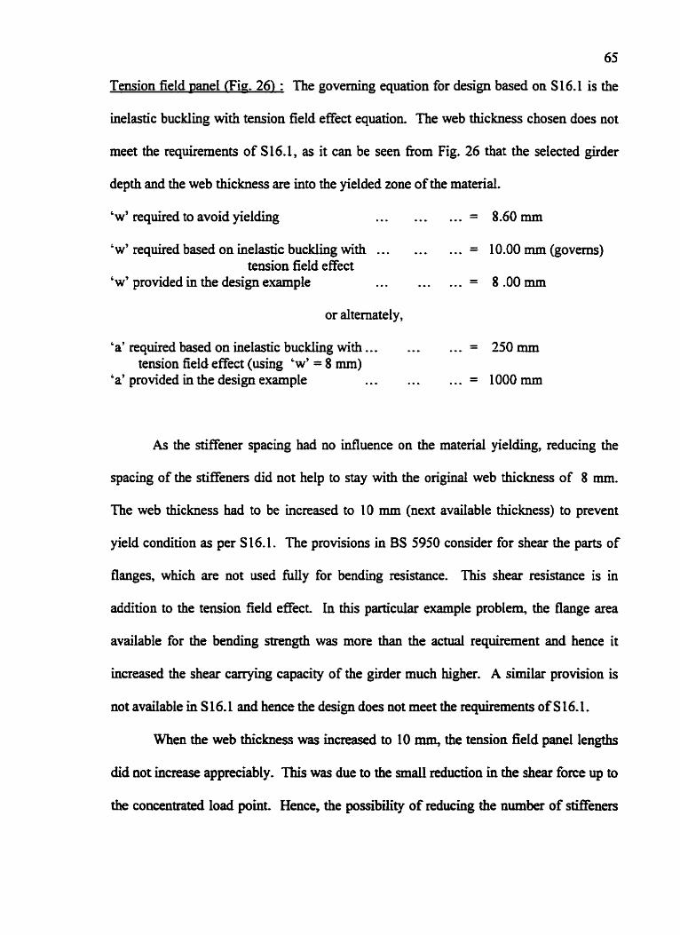
65
Tension field ~ane l (Fig. 26) : The governing equation for design based on S 16.1 is the
inelastic budding with tension field effect equation. The web thickness chosen does not
meet the requirements of S16.1, as it can be seen from Fig. 26 that the selected girder
depth and the web thickness are into the yielded zone of the material.
'w' required to avoid yielding .,, ,.. ... = 8.60mm
' w' required based on inelastic b u c f i g with . . . ... ... = 10.00 mm (governs) tension field effect
'w' provided in the design example ... ... . = 8.00rnm
or alternately,
'a' required based on inelastic buckling with ... . . - .,, = 250 mm tension field effect (using 'w' = 8 mm)
'a' provided in the design example ... .. . ... = lOOOmm
As the stiffener spacing had no influence on the material yielding, reducing the
spacing of the stiffeners did not help to stay with the original web thickness of 8 mm.
The web thickness had to be increased to 10 mm (next available thickness) to prevent
yield condition as per S 16.1. The provisions in BS 5950 consider for shear the parts of
flanges, which are not used i l l y for bending resistance. This shear resistance is in
addition to the tension field effect. In this particular example problem, the flange area
available for the bending strength was more than the a c t d requirement and hence it
increased the shear carrying capacity of the girder much higher. A similar provision is
not available in S 16. L and hence the design does not meet the requirements of S 16.1.
When the web thickness was increased to 10 mm, the tension field panel lengths
did not increase appreciably. This was due to the small reduction in the shear force up to
the concentrated load point Hence, the possibility of reducing the number of stiffeners

66
could not be achieved. The shear force became very small after the concentrated load
point and a . unstiffened girder design was adequate for the midspan. Hence, it is possible
to eliminate the two stiffeners provided in the mid-span. However, due to the live load
contribution of the two concentrated loads in the mid-span of the girder, the shear force is
likely to increase at these locations when one of the live loads is not present. Hence, the
provision of two stiffeners in the mid-span is acceptable.
The decrease in moment of resistance of the girder due to web thickness
reduction ( w = 8 mm) was very small. This did not S e c t the overall girder design, as
the factored bending moment for the girder was less than the decreased moment of
resistance. The optimization study for the girder depth indicated that the chosen depth is
the most economical.
Case 12
The original design example was based on CSA S 1 6.1.
Anchor Panel (Fie. 1%: The web thickness chosen in this example does not quite meet
the elastic buckling requirements of S16.1. There is an error in the example problem
presented in the structural steel design textbook. The resistance factor cp for the shear
stress was not considered when determining k,. This results in larger spacing of the
intermediate stiffener and hence does not meet the requirements for elastic buckling.
When this correction is applied such as reducing the anchor panel length from 1600 mm
to 1398 mm, the elastic buckling requirement will be satisfied, as seen below :
'w' required based on elastic buckling . . .... ,.. = 10.36 mm
'w' provided in the design example ... . , --, = 10.00 mm
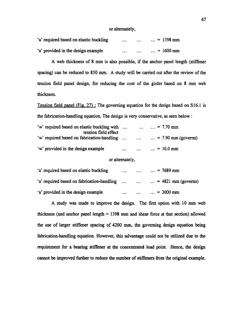
or alternately,
'a' required based on elastic buckling ... . *. ... = 1398 mm
'a' provided in the design example -.. .. . ,.. = 16OOmm
A web thickness of 8 mm is also possible, if the anchor panel length (stiffener
spacing) can be reduced to 850 mm. A study will be carried out after the review of the
tension field panel design, for reducing the cost of the girder based on 8 mm web
thickness.
Tension field panel (Fig. 27) : The governing equation for the design based on S16.1 is
the fabrication-handling equation. The design is very conservative, as seen below :
'w7 required based on elastic buckling with ... . .,. = 7.70 mm tension field effect
'w' required based on fabrication-handling . . . + - * . . . = 7.90 mm (governs)
'w7 provided in the design example ... ... . ,, = 10.0 mm
or alternately,
'a7 required based on elastic buckling ... ,.. . . , = 7689 mm
'a' required based on fabrication-handling . . . ..* . . . = 4821 mm (govern)
'a' provided in the design example . .. ..* ,.. = 3000 rnm
A study was made to improve the design. The first option with 10 mm web
thickness (and anchor panel length = 1398 rnm and shear force at that section) allowed
the use of larger stiffener spacing of 4200 rnm, the governing design equation being
fabrication-handIing equation. However, this advantage codd not be utilized due to the
requirement for a bearing stiffener at the concentrated load point Hence, the design
cannot be improved M e r to reduce the number of stBenen from the original example.
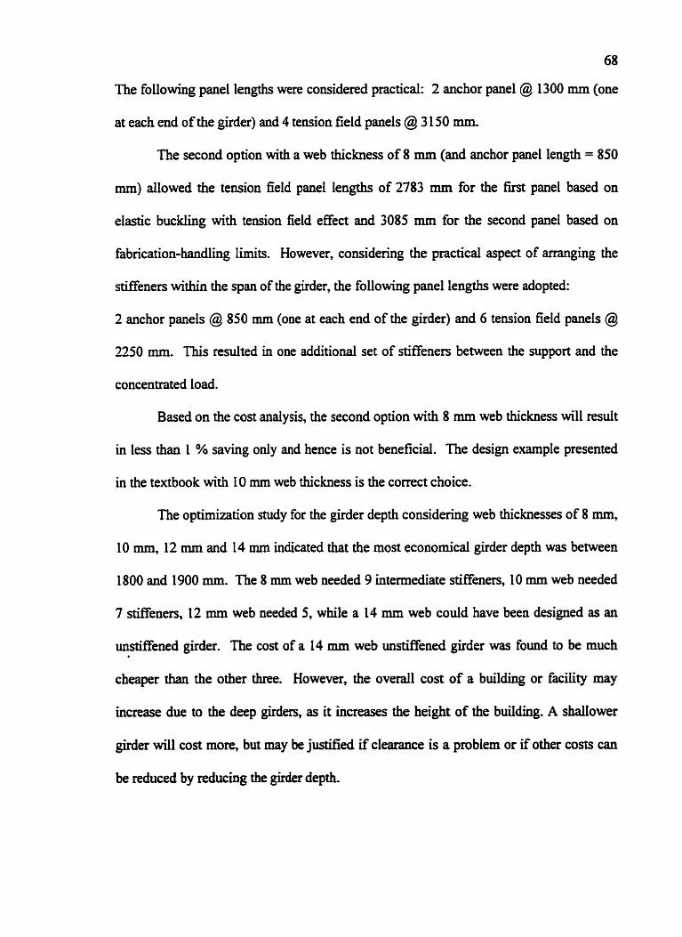
68
The following panel lengths were considered practical: 2 anchor panel @ 1300 rnm (one
at each end of the girder) and 4 tension field panels @ 3 150 mm.
The second option with a web thickness of 8 mm (and anchor panel length = 850
mm) allowed the tension field panel lengths of 2783 mm for the first panel based on
elastic buckling with tension field effect and 3085 mm for the second panel based on
fabrication-handling limits. However, considering the practical aspect of arranging the
stiffeners within the span of the girder, the following panel lengths were adopted:
2 anchor panels @ 850 mm (one at each end of the girder) and 6 tension field panels @
2250 mm. This resulted in one additional set of stiffeners between the support and the
concentrated load.
Based on the cost analysis, the second option with 8 mm web thickness will result
in less than I % saving only and hence is not beneficial. The design example presented
in the textbook with I0 mm web thickness is the correct choice.
The optimization study for the girder depth considering web thicknesses of 8 mm,
10 mm, 12 mm and 14 mm indicated that the most economical girder depth was between
1800 and 1900 mm. The 8 mm web needed 9 intermediate stiffeners, 10 rnm web needed
7 stiffeners, 12 mm web needed 5, while a 14 mm web could have been designed as an
unstiffened girder. The cost of a 14 mm web Mstiffened girder was found to be much b
cheaper than the other three. However, the overall cost of a buiIding or facility may
increase due to the deep girders, as it increases the height of the building. A shallower
girder wil l cost more, but may be justified if clearance is a problem or if other costs can
be reduced by reducing the girder depth.

Web Thickness W ( mm )
Lqend: Eq.? - w limited by yield Eq.2 - w to avoid vellical budding of compresston flange Eq.4 - w Iw unstifkmd girder limited by inelastic budding Eq.5 - w f6r unstMreneed girder limited by elastic W n g Eq.6 - h e ~ e t a s t i c a n d ~ k r d r l i n g z o n e s Eq.8 - w for anchor panel limited by inelastic budding Eq.9 - w for anchor panel fimited by elastic krddi ~ q . 3 0 - w r i t ~ ~ ~ ~ m r i c a t i o c l ~ m r i w, - w r n w n r o r ~ d g i * W, - w minimum fDI anchor panel influenced by alh ratio
Vf l.62 MN = 63.3 w a 7.94 mm h r 2540 mm a 1 h = 0.30 Fy = 248 MPa
Fig. 4 ANCHOR PANEL - Case 1

Lqpnd: Eq.1 - w limitdbyy#ld Eq.2 - w to avoid vutiepl budding of compmsicm flange Eq.4 - w for msM&md g&der limited by bwllstic budding Eq.5 - w for unstjWhd girda limited by eI8stic budding Eq.6- l i r l e d M d h g ~ a n d ~ ~ r 0 n e S Eq.8 - w f t x a n c h c K p a W ~ b y M a s t i c W n g Eq.9 - w fwMchorprmIhn'iby~*budd~ ~q.10-w r ibased~rr- w, - w m o w f& uwmmd
& -mg - W, - w minimum& a n c h o r ~ ~ ~ b y a l h r a t b
Vf r0.9?S MN 4 158.7 w s 6.35 mm h a 2032 mm a I h = 0.31 Fy = 248 MPa
Fig. 5 ANCHOR PANEL - Case 2

This case is not applicable due to continuity at the support
Vf 2,40 MN kws41.0 ~ ~ 9 . 5 3 m m h ~ 2 5 4 0 mm a/h=0.38 Fy= 540 MPa
Fig. 6 ANCHOR PANEL - Case 3
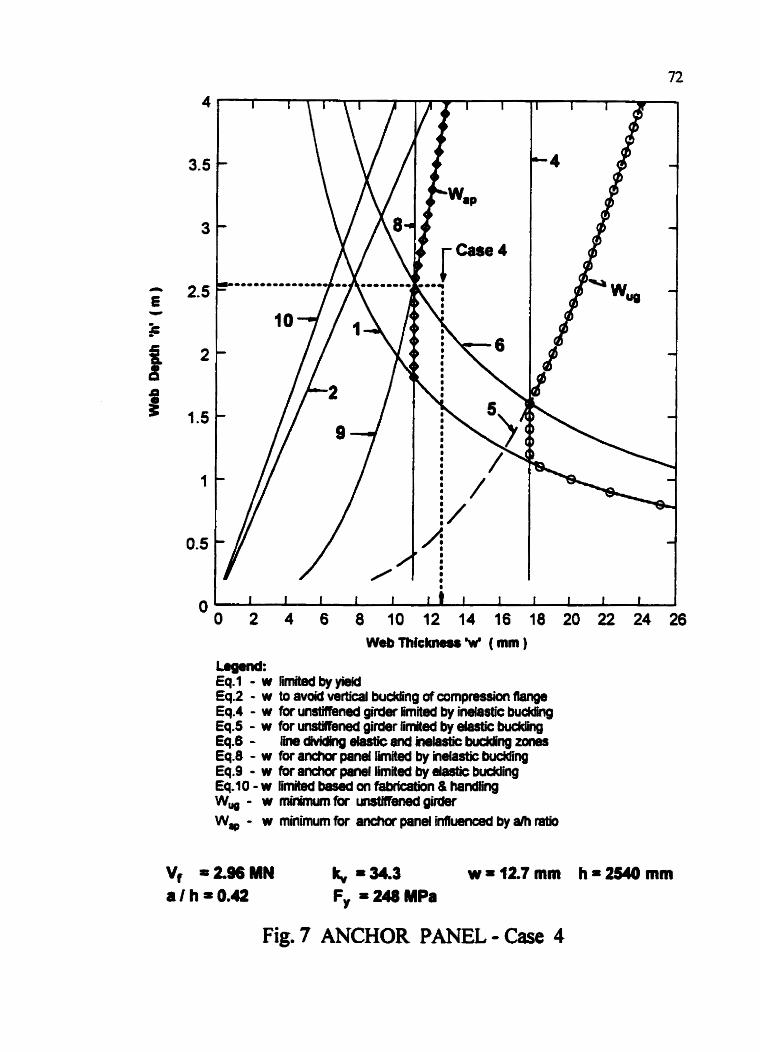
Web Thickness W ( mm )
lag8nd: Eq.1 - w limitedby yield Eq.2 - w to avoid vertical buckling of compression flange Eq.4 - w for unstifbned girder limited by inelastic budding Eq.5 - w for untMened girder limited by elastic budding €9.6 - 6 i M k r g e b t k md i r rektk budding zones Eq.8 - w for snchor panel Urnited by inelastic budding Eq.9 - w for anchor paml limletd by elastic budding Eq.10 - w limited bewd on fahication & handing w, - w minimme lJlwmenedgi*
Vf =Z%MN It = 34.3 w=f2.7mm hi254Omm aths0.42 F, = 248 MPa
Fig. 7 ANCHOR PANEL - Case 4

Lagend: Eq.1 - w limited by yield Eq.2 - w to avoid wrtical budcling of canpressiun flange Eq.4 - w for uwthwd girder limited by i n e l m budding Eq.5 - w for Or girder limited by elastic buddhg Eq.6 - fine dvidhg drr(ic and imhtk budding zones Eq.8 - w for anchor paw limited by wastic krc~ng Eq.9 - w for anchor panel limited by d a e budding Eq.10 - w IkmM based on faklcatiDn & handting W, - w minimum unstiff- gir&s W, - w minimum ibr anchor paned inlluecmd by a h ntio
Vf l.0 MN k, a 20.9 ~ = 7 . 9 4 m m hW625mm ath=0.56 F, = 248 MPa
Fig. 8 ANCHOR PANEL - Case 5
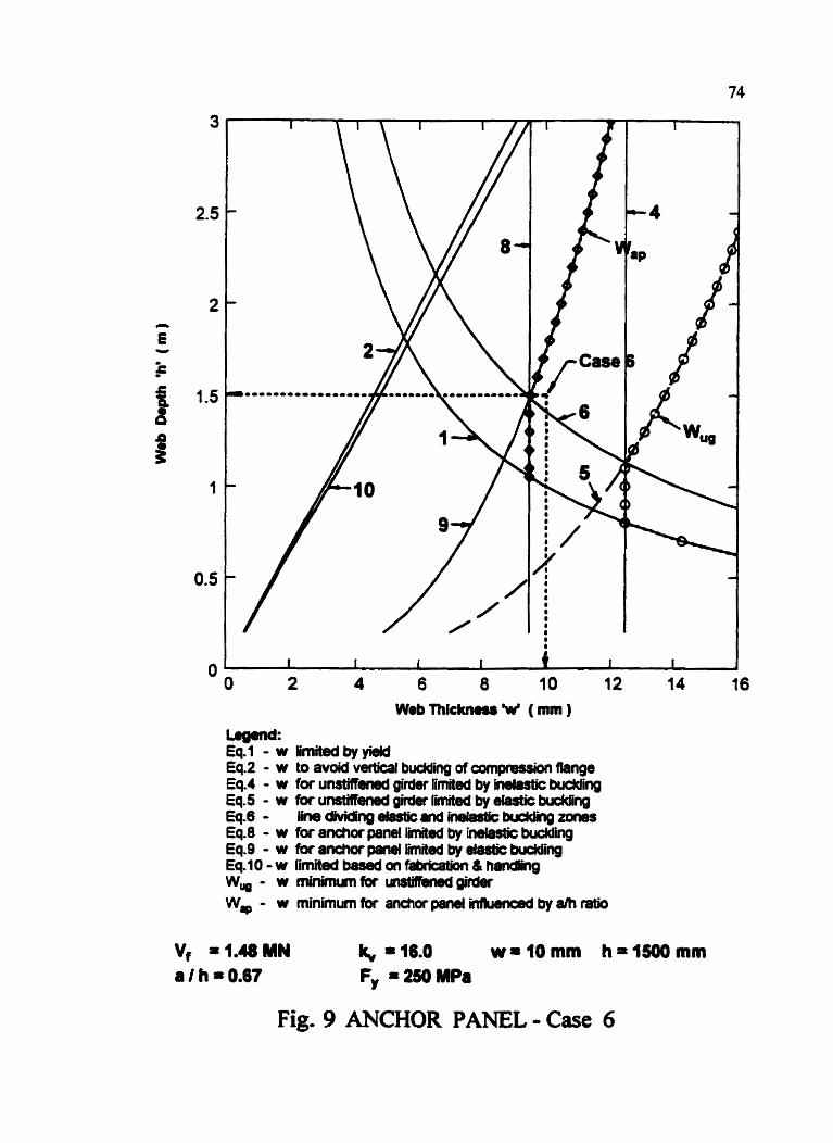
-= Eq.1 - w limited by yield Eq.2 - w to avoid vertka1 buddi i of compmssion flange Eq.4 - w for unstiffisned girder limited by W8sW budding Eq.5 - w ibr unstiRened gimr limed by em&k buckling Eq.6 - l i n e B v i e n g r L g t i c a n d ~ ~ o # w w Eq.8 - w foranchwpanetf linited by inelastic budding Eq.9 - w for anchor ponl limited by elastic buHng Eq.10 - w EnW based fabr[catiPn & h-9 w,- wminimunraunrtinbrwdpirdr
Fig. 9 ANCHOR PANEL - Case 6

Legend: Eq.1 - w limitedbyykld Eq.2 - w to avoid v-l budding of compression flange Eq.4 - w fw unstin& girder limited by inefastic budding Eq.5 - w for umtMer#d girder limited by elastic b u d d i i Eq.6 - lk~diWhgrlu(icndWekrddhp~one~ Eq.8 - w for anchor penel limited by indastic budding Eq.9 - w fa anchor panet M e d by elastic budding ~q-10-w r i m hnlrrvr~nfakicgfiocl w,- W m i r L n U m f o r ~
8 h a m gi-
W, - w minimum fix anchor panel i~~ by ram
Vf *3.11 MN lq, I 16.0 wr16mm h = l S O m m a I h = 0.67 Fy = 250 MPa
Fig.10 ANCHOR PANEL - Case 7

Web Thickness W ( mm )
Legand: Eq. 1 - w limited by y W Eq.2 - w to avoid mtia budding of compression flange EqA - w @r urWT(M8d girder limited by inehsttc budding Eq.5 - w for msmmd girderllmi€d byetastickrddng Eq.6 - ~ ~ J I I t i c a n d ~ b u d d h g z o n # Eq.8 - w fbr anchor prm Bmited by inelastic budding Eq.9 - w (b ranc t lo f~ I 'm i !edby~ -~ Eq.10-w limitedbawdanfaklcetion&hadAng W, - w minimum fw unMkmd girder W, - w minimurnbr a n d o r p a m f i ~ b y r l h r a t i o
Vf 1.39 MN k, * M.6 w r 9.53 mm h + 1575 mm aIh=0.68 Fy = 248 MPa
Fig. 1 1 ANCHOR PANEL - Case 8

L q m d : Eq.7 - w ihrhdbyyidd Eq.2 - w to avoid vertical buckJing of awnprwsion flange Eq.4 - w fw unstifkwd girder limited by inelastic budding Eq.5 - w for unsMmW girder limited by &$tic budding Eq.6- lmdivWngdWcmdimWicbuckGn~zones Eq.8 - w for Pncha pand limited by inelastic budding Eq.9 - w for anchor pawl limited by astic buddii Eq.10 - w limited based on lmfkmon & handlim Wuo - w minimum ftr unrti(lw#d girder W, - w minimum fbr anchor p a w inlruemd by alh ratio
Vf '2.0 MN k, = 44.0 w114mm hr2400mm a / h = 0.73 Fy = 300 MPa
Fig. 12 ANCHOR PANEL - Case 9

Web T h k k ~ ~ W ( mm )
-= Eq.1 - w l i m i e c f b y ~ Eq.2 - w to avoid vertical buddig of compeMkn flange Eq.4 - w for unsWi3ned girder limited by iW(ic buckling Eq.5 - w for unstH@ned @rkw limited by elastic W n g Eq.6- I h . d h M m ~ ~ . n d h & ~ b u c k l i h ~ ~ Eq.8 - w fw anchor pml limited by imlatic buddng Eq.9 - w for achor panel mited by daWc budding Eq.10 - w limited based on fiMcaWn & handling W, - w minimum wtifbmd girder W, - w minimum for anchor panel i M m by a/h ratio
Vf 2.86 MN k, % 13.5 ~ * 1 4 m m hrZOOOmm a l h -0.75 Fy = 250 MPa
Fig. 13 ANCHOR PANEL - Case 10

Web Thickness W ( mrn )
-= Eq.1 - w ihritd by yidd Eq.2 - w to avoid vcwticsl budding d compfemh flange Eq.4 - w iw unstifhmd girder limited by inetmtk buddhg Eq.5 - w for tmMMmd girder limited by elastic budding Eq.6 - 8 1 dWhQ elastic uld h b S t k krc#lng Z-S Eq.8 - w for anchar panel limited by inelask budding Eq.9 - w for anchor panel limited by elastic buWnp Eq.10 - w limited based on fhb@Won & handling w, - w minsnunlbr uulilhrwdglr#n
Fig. 14 ANCHOR PANEL - Case 1 I

-= Eq.1 - w liMd by yirld Eq.2 - w to avoid v d a a l budding of compmssh Range Eq.4 - w lor mtifbnd girder limited by imfastic budding Eq.5 - w for cmMbmd gCQK fiited by elastic budding Eq.6 - ~ ~ d v i d h O ~ W s n d ~ ~ Eq.8 - w f6r anchar par#( limited by indmtk budding Eq.9 - w fi#wrcharpmi lhiited by elasticbuckling Eq-fO-w I L n i t c l d ~ ~ h b d ~ & h W h g W, - w rnhsnumlbr t m M R m d m W, - w miiimum tor anchor paw inllumad by a/h ratio
Vf * 1.08 MN 1 8.4 wt.(Omm hm14amm a f h = 1.14 F, = 350 MPa
Fig. 15 ANCHOR PANEL - Case 12

-= Wab Thickness W ( mm ) Eq.1 - w limited by yie# Eq.2 - w t 0 a v o i d ~ b u d d i n ~ d o m p w r i o n f i . n ~ Eq.4 - w for unstifhw girder limited by inelastic budding Eq.5 - w for unsWimd girder limited by dastrc budding Eq.10 - w limited based an Dbrlcaion & handing Eq-22- w b 8 ! W 0 n ~ ~ ~ g h O u # l g d b y ~ l s t i 0 Eq.23 - w based an imhstk budding + todon Mld Eq.24- w basedonc-=buddif'Q+mw W - w minimum fw gi- W T ~ - w minim~m(br&rria,Md~in(l#lgdbyshrPtio
Fig. 16 Tension Field Panel - Case 1

-= Web Thickness W (mm ) Eq.1 - w limitedbyw Eq.2 - w bavo#var(icrlWr~g~fmpnssionmW EqA - w for u n s t i n d gifder limitd by inelastic buckling Eq.5 - w for un-w girder limited by ahistic budding Eq.10-w ilmitedbamdonfsbricl(#n&hmdting Eq.22- w badonMIdicbucklinpiMuermdby~rati0 Eq.23 - w b a a on in- budding + tension Md Eq.24- w WmdOnWcbuddhg+tetl&n(kld W, - w minimunlorunrti(hmd@rder wTF - W f n i n h u m ( b r ~ ~ p e r # l ~ b y s m r s l i o
Fig. 17 Tension Field Panel - Case 2

Legend: Web Mckmu X ( mm ) Eq.1 - w fimitedbyyk# Eq.2 - w t o a v o i d ~ ~ d c o m p n w d o n f l ~ Eq.4 - w fw unsWmed girder limited by in- budding Eq.5 - w fw unsWkW g&der limited by elastic budding Eq.10 - w limited based on DMmtim & handlhg Eq.22- w b a r c l d o n ~ b u d d i n g i n ( l ~ b y a / h r o t i o Eq.23 - w based on indmtic budding + tension field Eq.24 - w based on 9lab;e buddi i + tension fwd W, - w minimum lbr umtiRmed girder WW - w m i n i m u m W t m s b n M d p s n r l ~ b y a l h n t i o
Vf 2.32 MN fq, 1 11.1 ~ ~ 9 . 5 3 m m hr2540mm a / h = 0.87 F, = 340 MPa
Fig. 18 Tension Field Panel - Case 3

-= Web Thlcknrr X ( mm ) Eq.1 - w limitetdbyyield Eq.2 - w t o a v o k f ~ ~ n g d c o m p n # r i a n ~ Eq.4 - w for unMened girder Emited by indmtk budding Eq.5 - w br u r t s ~ gWw fmited by etastic budding EelO-w Omibdbewd~ntbbdcatim&hadhg Eq.22- w b l r w d o t t m h ~ I ~ @ ~ ~ - b y a l h m Eq23 - w based an inefastic budding + tension Wd Eq.24 - w based on cllwlic bud din^ + tmrion MJd W, - w minimum tor tmMbmd g i d a WF- w m h m m f o f ~ M # ~ i n i l ~ b y ~ r a t E o
Vf 2.73 MN = 34.3 wr12.7mm hr2540mm a I h = 0.42 Fy = 248 MPa
Fig. 19 Tension Field Panel - Case 4
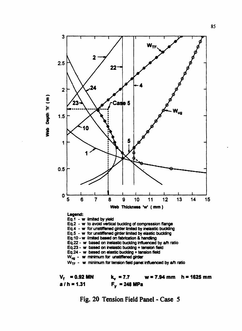
Web Thlcknm W (mm)
-= Eq.1 - w IimRd by yie# Eq.2 - w to avoid vettical buckling of compression flange Eq.4 - w for unstifhmd girder limited by inelastic budding Eq.5 - w for u r W M e d girder limited by e 6 c budding Eq.40-w l i m R e d b . r r d o n ~ & h v r d h g Eq.22 - w based on inelmtic budding inlluenc8d by ratio Eq.23- w W s e d o n i r t e J 8 s b i c b u d d i i + t ~ ~ Eq.24- w basedon~buddinp+tmrionfiald w, - w mhmmm lJnsmmdm WF - w minimumfcrtensionMdpa~tnl l~by.hrat io
Vf -0.92 MN k, r f.7 w r 7.94 mm h r I625 mm a I h ='1.31 F, = 248 MPa
Fig. 20 Tension Field Panel - Case 5

Wsb Thicknu8 W ( mm ) Legend: Eq. t - w limited by yield Eq.2 - w t o a v o i d - k r d d i i o r c o m ~ ~ Eq.4 - w for unrtif6emd girder limited by irtetastic budding Eq.5 - w for un- Qdrr limited by .Irstic budding Eq.10 - w limited based on hkieslion & hsndng Eq.22- w b a s e d o n ~ ~ i ~ b y a h n ( i 0 Eq.23 - w based on imbstic buddihg + tmsian field Eq.24- w ba~on&ic~+ tmr ipmf ic r# Wto - w minimum for u n s W F d girder ww - w mhmunfOt~tirr#p8m(in(hnrmrdby~rstiD
Vf =q.30MN k,, % 16.0 w=IOmm h=15OOmm a l h = 0.67 Fy = 250 MPa
Fig. 2 1 Tension Field Panel - Case 6

L8Q8nd: Eq.1 - w limited byw Eq.2 - w to avoid v e d i d budding o f c o m p ~ * o n flange Eq.4 - w lor unaiffbned girder limited by inelastic budding Eq.5 - w for u- gLdw mited by elastic budding ~q.10-w rnwbswdmamwtmhrndlhp €9.22 - w based on inelae budding influenced by alh ratio Eq.23 - w based on in- budding + t e n s h field Eq.24 - w based 00 Mastic budding + twion field w, - w frlinimmm-m WF - w minimum fbr tension field panel influenced by a/h mtb
Fig. 22 Tension Field Panel - Case 7

w: Wab Thlcknar W (mrn ) Eq. 1 - w limited by yield Eq.2 - w t o r v o i d ~ k K W ~ a f c ~ m ~ ~ Eq.4 - w ib umtifhed girdw fimited by inelastic budding Eq.5 - w br unsti(lbnrd gkda rimM by elastic budding Eq.10 - w limited based on fabrimim & handiing €9.22- w b a s e d o n ~ ~ m g ~ b y e l h r e t k Eq23 - w based on inelastic buddimg + tcwpion fiW Eq.24- w ~ o n ~ s t i c ~ n g + t 8 1 1 s i o n ~ W, - w minimum fkx ~~ girds
Vf 3 1.35 MN k, % 14.9 wr9.53mm hr1575mm a / h = 0.7 Fy = 248 MPa
Fig. 23 Tension Field Panel - Case 8
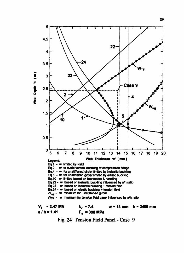
-= wab mickn- w ( mn ) Eq. t - w limited by yiw Eq.2 - w t ~ R l o # ~ k n W n g d ~ m ~ ~ Eq.4 - w (or U M ' girder limila by iWastic budding Eq.5 - w for un- gifder limited by elastic budding Eq.10-w M t W W ~ n f - & h s m Eq.22- w ~ a n i ~ k n l d k g h f u u e r m d b y a h r a t i o Eq.23 - w based on inelastic budding + tenrion field Eq.24 - w w be 6faar b u d d i i + tension (kld W, - w minimum for unainened girder WTF - w m k m L m f b r t M i o n f i e l d p a n e l ~ b y ~ r a t i o
Fig. 24 Tension Field Panel - Case 9

Web Thlcknms W (mm)
Lqpnd: Eq-1 - w limiidbyyidd Eq.2 - w to avoid vcwtitpl budding of canpnuicn flange Eq.4 - w fix unsMWmd girder l i i ed by Mas& budding Eq.5 - W ibru- ~ W 8 f h b d by bUCkfIflg Eq.10-w G t ~ ~ i b d w ~ n - & h a n d h g Eq.22 - w baserd on inelmtic budcbg i n t l m by ah ratio Eq23- w b a s e d o n i ~ b u d d i n g + t e n s i o n ~ Eq.24 - w bercld m elastic budding + tensiorr tiefd w, - w mimun*brunrvmnrdQrdw Ww - w m i n i m n r f a r t ~ f i ~ p a n e I i n I T ~ b y a l h r a t i 0
Vf = 2.51 MN It,, = 13.S ~ - 1 1 4 m m h~2OOdmm a I h = 0.75 Fy - 250 MPa
Fig. 25 Tension Field Panel - Case 10
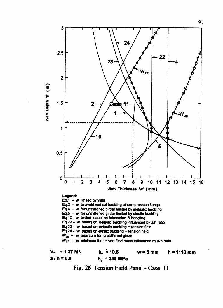
Web Thickness W ( mm )
Legend: Eq. l - w limited by yield Eq2 - w to avoid vertical budding af compression flange Eq.4 - w fW unstiftmed girder limited by inelastic buckling Eq-5 - w fw unstiffened girder limited by elastic budding Eq.10 - w limited based on fabrication & handling Eq.22 - w based on ineiastic budding inffuenard by a h ratio Eq.23 - w based on inelastic buckling + tension field Eq.24 - w based on elastic budding + tension field W, - w minimum (br unstiffend girder WF - w minimum fw tension fiefd panel infiuenced by alh ratio
a f h = 0.9 Fy = 245 MPa
Fig. 26 Tension Field Panel - Case I I
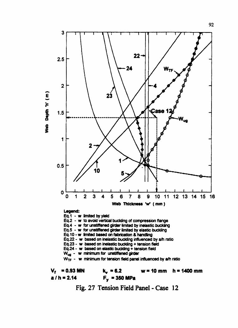
-= Eql - w limited by yield Eq.2 - w to avoid v m t b I buclding of cumpmssh flange Eq.4 - w for unsMmed girder limited by inelastic buckling Eq.5 - w for unsMhM girdw Med by elastic budding Eq.10-w rn~edb€mdarfibricaion&hnd~ Eq.22 - w based on inelastic budding influem by a/h ratio Eq.23 - w based on inelastic knwng + tension field Eq.24 - w based on elastic W i n g + tension field w,- W r n i c a ~ p i r d a W- - w m*nimum for temion tb# panel influenced by a* ratio
Vf 0.93 MN 16 % 6.2 w=iOmm h=l406mm a I h = 2.14 F, = 350 MPa
Fig. 27 Tension Field Panel - Case 12
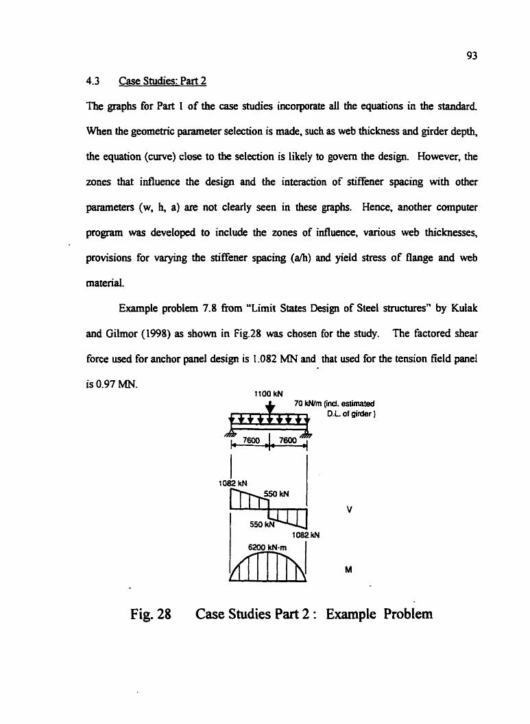
4.3 Case Studies: Part 2
The graphs for Part 1 of the case studies incorporate all the equations in the standard,
When the geometric parameter selection is made, such as web thickness and girder depth,
the equation (crwe) close to the selection is likely to govern the design. However, the
zones that influence the design and the interaction of stiffener spacing with other
parameters (w, h, a) are not clearly seen in these graph. Hence, another computer
pro- was developed to include the zones of influence, various web thicknesses,
provisions for varying the stiEener spacing (ah) and yield stress of flange and web
material.
Example problem 7.8 from "Limit States Design of Steel structures" by Kulak
and Gilmor (1998) as shown in Fig.28 was chosen for the study. The factored shear
force used for anchor panel design is 1 -082 MN and that wed for the tension field panel
1100 w 70 W m (ind. estimated
0.L of girder )
Fig. 28 Case Studies Part 2 : Example Problem

Fig. 29 w vs. h for Anchor Panel

Fig. 30 a VS. h for Anchor Panel
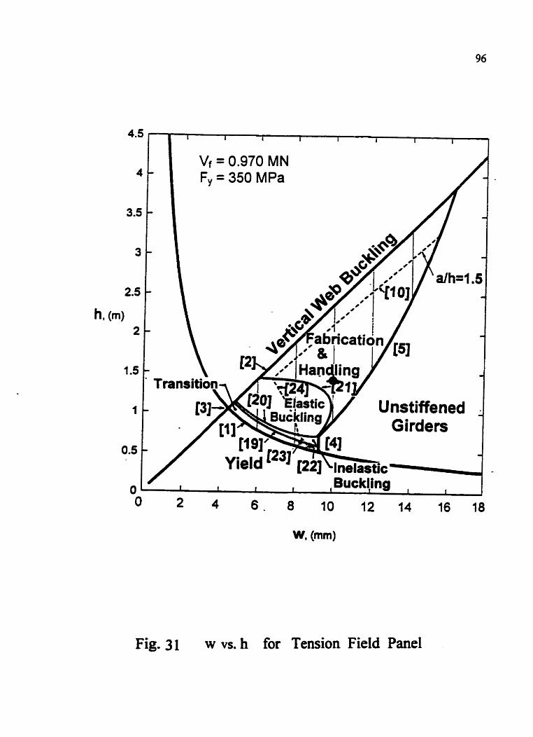
Fig. 3 1 w VS. h for Tension Field Panel
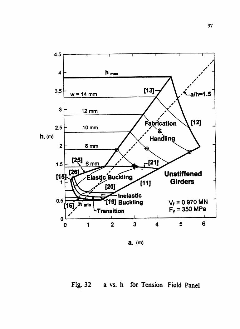
4 - 8-
I I
3.5 - w = I 4 r n m
Vf = 0.970 MN Fy = 350 MPa
Fig. 32 a vs. h for Tension Field Panel

98
A set of graphs (Fig. 29 to Fig.32) have been developed, for 'w vs. h' and 'a vs. hT
that include both anchor and tension field panels for the example problem. These graphs
incorporate all 26 design check conditions obtained fiom the code equations (Table I).
The graphs show all the zones that influence the design, such as yield, transition,
inelastic buckling, elastic buckling, fabrication and handling, vertical buckling,
unstiffened girder zone and an example curve ah = 1.5 through the zones. The general
procedure to use the graphs is to start with certain assumptions for 'ah'. The graph for
'w vs. h' indicates the zone (to the right side of the chosen a/h c w e ) where selection is
possible. The selection zone is bounded by the a/h = 1.5 curve (Eq. [8], [9], [lo] for the
anchor panel and Eq. [lo], [22], [23], [24] for the tension field panel) at the top and to the
left, the unstifiened girder curve Eq. [4] and [S] on the right and the yield curve Eq. [I] at
the bottom. The selection of 'w', 'hT and the maximum allowable stiffener spacing 'aT -
can also be made fiom the 'a vs. h' graph. For any chosen 'w' and 'h', the smallest value
of 'a' will be satisfactory. These graphs clearly indicate dl the S 16.1-94 equations, the
applicable design zone, available slack for the chosen design parameters and the effect of
changing any one of the parameters in relation to another. The solution for the example
problem is shown as a circular dot (a) in the graphs (Figs. 29 to 32). This example was
analyzed earlier in Chapter three as Case 12 (Fig. 15 and 27) for both anchor and tension
field panels.
4.4 DISCUSSION OF GRAPHS FOR ANCHOR PANEL
4.4. 1 Web Thickness Limitations
Thinner webs and deeper sections may be used for the Mened girders because the
intermediate stiffeners reduce the a/h ratio, and thereby increase the plate buckling
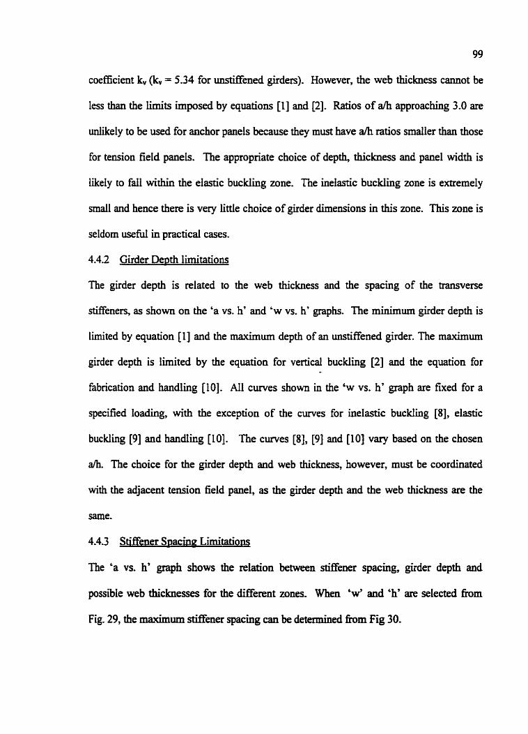
99
coefficient k,, (kv = 5.34 for unstiffened girders). However, the web thickness cannot be
less than the limits imposed by equations [I] and [2]. Ratios of a h approaching 3.0 are
unlikely to be used for anchor panels because they must have a/h ratios smaller than those
for tension 6eId panels. The appropriate choice of depth, thickness and panel width is
likely to fall within the elastic buckling zone. The inelastic buckling zone is extremely
small and hence there is very little choice of girder dimensions in this zone. This zone is
seldom useM in practical cases.
4.4.2 Girder Depth limitations
The girder depth is related to the web thickness and the spacing of the transverse
stiffeners, as shown on the 'a vs. hT and 'w vs. h' graphs. The minimum girder depth is
limited by equation [I] and the maximum depth of an unstiffened girder. The maximum
girder depth is limited by the equation for vertical buckling [2] and the equation for
fabrication and handling [lo]. All curves shown in the 'w vs. h' graph are fixed for a
specified loading, with the exception of the curves for inelastic buckling [a], elastic
buckling [9] and handling [lo]. The curves [8], [9] and [lo] vary based on the chosen
ah. The choice for the girder depth and web thickness, however, must be coordinated
with the adjacent tension field panel, as the girder depth and the web thickness are the
same.
4.4.3 Stiffener S~acing Limitations
The 'a vs. h' graph shows the relation between Mener spacing, girder depth and
possible web thicknesses for the different zones. When 'w' and 'h' are selected h m
Fig. 29, the maximum stiffener spacing can be determined h m Fig 30.

4-5 DISCUSSION OF GRAPHS FOR TENSION F E D PANEL
4-5-1 Web Thickness Limitations
Several o f the equations, which limit the web dimensions for tension field panels, are the
same as for anchor panels. The minimum web thickness, minimum depth and maximum
depth criteria are the same as for the anchor panels. The minimum web thickness is
governed primarily by the fabrication and handling equation [lo] for the tension field
panels rather than the verticai buckling equation [2], which governs for the anchor panel.
The graph in Fig. 3 1 shows clearly that the inelastic bucW ing zones contribute little to the
tension field panel design.
4.5.2 Girder Depth Limitations
Tension field action increases the shear strength in part of the inelastic buckling zone as
well as the entire elastic buckling range. The minimum girder depth is governed by the
elastic buckling equation [24] and the maximum depth for an uostiffened girder, equation
[S]. The maximum girder depth is limited by the fabrication and handling equation [lo].
As seen h m the graphs in Fig. 3 l and 32, the ineiastic buckling zone is very d l . It is
most likely that the tension field panel will fall within the fabrication and handling or the
elastic buckling zone.
4.5.3 Stiffener S~acing Limitations
The 'ah' graphs in Fig. 32 can be interpreted in a similar manner as for the anchor panel.
The equations likely to limit the rmximum panel width are the fabrication and handling
equations [11] and [12]. When the vertical buckling equation [2] is combined with the
fabrication-handling equation [lo], it defines the equation [I31 for a/h, which is 12 for

101
the tension field panel [ah = ( Fy/3 19.5)~ = 12 for Fy = 350 MPa]. When ah < 12, the
vertical buckling criteria is likely to govern the design and for ah B1.2, fabrication-
handling equation will govern the design. However for shallow girders, the elastic
buckling is more likely to govern the design than the vertical buckling or fabrication-
handing limit
4.6 Optimum De~th
A study of the cross-sectional area of various depths of the girder for Example 7.8
from Kulak and Gilmor was made. The three web thicknesses that were considered were
8 mm, 10 mm and 12 mm. Although this girder could have been designed with a 6 mm
web, it would have to be very shallow with a large number of stiffeners. A web thickness
of 14 mm or greater could be designed as an unstiffened girder. This option should be
considered.
It was found that the optimum girder depth for all three web thicknesses was 1800
to 1900 nun, as indicated by circles on Fig. 30 and 32. The 8 mm web requires 9
intermediate stiffeners; the 10 mm web requires 7 stiffeners while a 12 mm web requires
5. I f the cost of web is based on $1.50/kg, and the installed cost of each stiffener is
assumed to be roughly $270, the 12 mm web with five intermediate stiffeners and a web
depth of 1800 mm was found to be marginalIy cheaper than the other two. A shallower
girder will cost more, but may be justified if clearance is a problem or if other costs can
be reduced by reducing the girder depth.

102
CHAPTER FIVE
COMPARISON OF THE SHEAR DESIGN PROVISIONS OF CSA S 16.1-94 WITH
OTHER CODES OF PRACTICE
5.1 General
The salient features of Canadian, American, British and Australian codes of
Practice have been presented in Table 7 for the shear design of plate girders.
The shear stresses adopted by these standards (items 1 to 5 in Table 7) have been
presented in Fig. 33,34 and 35 for Fy .c 350 MPa and ah = 0.5, 1.5 and 2.5 respectively.
It can be observed that BS 5950 and SI6.1-94 have higher allowable shear stresses as
compared to AISC and AS 4100 in the shear yield zone. In the buckling zone, the shear
stresses adopted by all the standards are close to each other except BS 5950. which has
lower allowable shear stress values.
The shear buckling coefficient k,, adopted by AISC, S16.1 and Vincent (1969)
have been presented in Fig. 36 (item 6 of Table 7).
The fabrication-handling and vertical flange buckling limits adopted by the
standards (item 7 and 8 of Table 6) have been presented in Fig. 37 to Fig. 40. It can be
observed &om these figures that all the standards are close to each other except AS 4100,
which has very conservative values. A comparison of some typical values adopted by the
standards for flange vertical buckling and fabrication-handling limits have been presented
in Table 8.
A detailed discussion of the shear design adopted by each standard is as foUows.
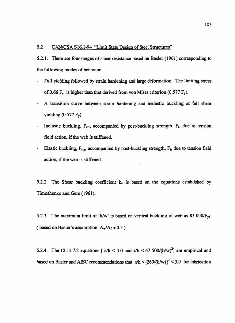
5 2 CANICSA S 16.1-94 "Limit State Desian of Steel Structures"
52.1. There are four ranges of shear resistance based on Basler (1961) corresponding to
the following modes of behavior.
- Full yielding followed by strain hardening and large deformation. The limiting stress
of 0.66 F, is higher than that derived h r n von Mises criterion (0.577 Fy).
- A transition curve between shain hardening and inelastic buckling at shear
yielding (0.577 F,).
- Inelastic buckling, Fai, accompanied by post-buckling snength, Fb dw to tension
field action, if the web is stiffened.
- Elastic buckiing, F,, accompanied by post-buckling strength, Fb due to tension field
action, if the web is stiffened.
5.2.2 The Shear buckling coefficient kv is based on the equations established by
Timoshenko and Gere ( 196 1).
523. The maximum Limit of 'h/w7 is based on vertical buckling of web as 83 OOO/Fyr.
( based on Basler's assumption Aw/Af = 0.5 )
52.4. The C1.15.72 equations [ dh < 3.0 and ah < 67 500/(h/w)~] are empirical and
based on BasIer and AISC recommendatiom that ah < [260/(h/w)]' < 3.0 for fabricati011

104
and handling convenience. The case studies fiom Chapter 4 indicated that this is often a
governing equation for the shear design of tension field panels.
As seen fiom the Fig. 37 to 40, the maximum allowable 'h/wY limit is governed
by vertical buckling for lower 'ah' ratios (ah 5 1.2 for Fyr =350 MPa) and by the
fabrication-handling limit for higher 'ah' ratios (ah > 1.2 for Fyr 4 5 0 MPa), which
typically apply to anchor and tension field panels respectively.
5.3 AISC LRFD Vol.1 (Second Edition)
5.3.1. The shear design procedure in this standard is simpler than the other codes. The
shear stress at buckling o, is simplified into non-dimensional form C, defined as the
ratio of shear stress G= at buckling to shear yield stress a,,. The total shear zone is
divided into three zones in AISC as compared t o four zones in CSA S16.1-94, the
transition zone between inelastic buckling and the yield being the additional one in CSA.
The maximum allowable shear yield stress in AISC is limited based on von Mises
criterion (Fs = 0.577 Fy) and the increase in shear stress due to strain hardening is
neglected. CSA S 16.1 -94 recommends a higher allowable shear yield stress (F, = 0.66
F,) considering the strain hardening. The recommended value of maximum allowable
shear yield stress in AISC resuits in simpler equations.
5.3.2 The two equations for shear buckling coefficients proposed earlier by
Timoshenko was simplified by Vincent (1969) as one equation, k=j+~/(a/h)'. This
equation was accepted for design purposes within the accuracy that the theoretical elastic

105
buckling solution agrees with a real plate girder. AISC adopted this equation fiom 1986.
A comparison of these equations is presented in Fig.36.
53.3 The maximum allowable 'Ww' is governed by the following.
Vertical buckling equations:
h / w ~ 5 2 5 2 / & for a/h < 1.5 ... ... [31]
h l w ~ 9 6 5 2 7 / , / ~ ~ for a / h > 1.5 . . ..* * - - 1321
Fabrication-handling equations:
It can be observed (fkom Fig. 37 to 40) that the maximum allowable 'h/w7 timit is
much higher in AISC than in CSA S 16.1, for 'am' values less than 1.5. This is based on
the recommendations of the ASCE-AASHO Joint Committee on Hybrid Girder Design.
The maximum allowable 'Ww' is governed by the curve 1 for Fyf < 400 MPa and
'ah7 < 1.0. When Fyr is > 400 MPa, the 'h/w' limit is governed by the curves 1 and 2
based on different zones of 'A' ratio. The 'h/w7 limits change abruptly between small
changes in the values of 'am' > 1.0 (ref. Fig.40). These equations require M e r study to
create a smooth transition of 'Ww' limits when Ffl > 400 MPa
A comparison of the limiting equations for fabrication and handling in AISC,
CSA S 16.1-94 and Basler's proposal was presented in Fig. 2.

5.4 British Standard BS 5950 - 1990 Part 1.
5.4.1 The shear design is made very simple but obscure by providing the values of the
shear stress in a tabular fonn based on the 'hfw' and 'ah', for both cases with and
without tension field effect In addition, tables have been provided to include for the
shear contribution of the flanges, when the flanges are not l l l y utilized for bending
resistance. However, the basis of these values is totally unclear. There are no
explanations for buckling zones or any equations for the tables. The allowable yield
shear stress is higher as compared to the other standards. The allowable shear stress in
the buckling zone is lower than others.
The maximum allowable 'hfw' is govemed by the following:
Vertical buckling equations:
h l w s 2 5 0 (345/Fy) foralh >1.5 ...
Fabrication-handling equations:
h/w5250 for a / h > l I/'
hiw5250(&) for a i h s l
It can be observed fiom Fig. 37 to 40 that the maximum allowable 'Ww' is govemed by
equations [34], [36] and [37l for Fyr < 345 MPa All the equations [34], [351, [36] and
[371 govern the 'hlw' for 345 MPa < Fyr l 4 5 5 MPa based on the 'am' ratio. For Fyf >
455 MPa, the maximum allowable 'hlw' is governed by the vertical buckling equations

107
[34] and [35] only and the fabrication-handling equations [36] and [37l have no influence
on the desiga This is different &om AISC and CSA S16.1, in which the fabrication-
handling limits still apply.
5.5 Australian Standard AS 41 00-1 990
The allowable shear stress is similar to AISC in both yield and buckling zones
(see Figs. 33 to 35). But the fabrication and handling limits are not directly specified.
The three limits ('h/w9 and 'ah') from CI. 5.10.4 (item 7 of Table 7) are similar to the
fabrication and handling limits adopted by the other standards. However, the maximum
allowable limit for 'Ww' based on C1. 5.10.4 is very conservative as compared to CSA-
S 16.1, AISC and BS 5950 (see Fig.37 to 40).
The vertical flange buckling (item 8 of Table 7 for unstiffened girders) is also
very conservative as compared to other standards.
5.6 Discussion on the recommendations for revisions to CSA S16.1-94 for Shear
Desim.
5.6.1 The shear yield stress F, = 0.66 F, is based on full yielding followed by strain
hardening. The study in the earlier chapter clearly indicated that the need to reach
Fs = 0.66 F, is unlikely in most practical cases, because these would be extremely
shallow beams. Hence it is not very beneficial to increase this valw beyond von Mises
criteria of Fs = FY /d3 . Other standards also specify values close to ~443.
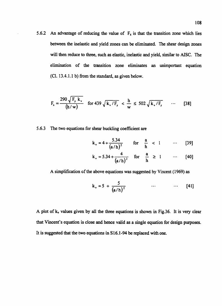
108
5.62 An advantage of reducing the value of Fs is that the transition zone which lies
between the inelastic and yield zones can be eliminated. The shear design zones
will then reduce to three, such as elastic, inelastic and yield, similar to AISC. The
elimination of the transition zone eliminates an unimportant equation
(C1. 13.1.1.1 b) h m the standard, as given below.
5.6.3 The two equations for shear buckling coefficient are
5.34 a k, =4+- for - c I * g o [39]
(alh)' h
A simplification cf the above equations was suggested by Vincent (1969) as
A plot of k,, values given by all the three equations is shown in Fig.36. it is very clear
that Vincent's equation is close and hence valid as a single equation for design pmposes.
It is suggested that the two equations in S 16.1-94 be replaced with one.

Cornpa5 No
1
2
L
4
5
CANICS A S 16.1-94 (CL13.11. CI.13.41.3, CI.IS.7.2)
V r = O A , F ,
h F, = 0.66Fv for - c 439 ,/-
W
290 4- " = (h lw)
fir 439 Jm < s 5 0 2 J m W
h F,=F,+F, f i r j 0 2 J n < - 1 6 2 1 , / m
W
290,/- Fm =
( h / w ) , F, = (0.5 F, - 0.866 F,)
6
AISC - Manual of Steel Constn Second Edition (Appc
v u < 0 v v n 4 " = 0 .
I -c, Vn = 0.6 A,F,, Cv + [ 1*15,,*
Cv = 1 f i r -<491[ h W
Not Applicub
C, = hl w fir 491 /z
1
5.34 a k , = 4 + f~ ;<I, k, =5.34+- 4 a 5 a 1
h F , = F , + c for 621,/md<- w
180 000 k, t ere = (h l w)' F, =(O.5Fy -0.866F,) {J-}
u - h
I
I
h / ~ ~ 8 3 0 0 0 / F , ~
303 369 kv h for - >
cv = (h/wI2 Fyr w
7
h / w 1 5 2 5 2 / J q for a / h S 1 .
h / w ~ 9 6 5 2 7 / J-1 ,
h a h a 67500 For-S150, -S3 and For->150, -r w tt w h (hi w)'
Note : 1. Units for stress = MPa and for dimensions = mrn. 2. Symbols and units of AISC, BS and P


Table 7
Comparison of Standards I AISC - Manual of Steel Construction, LRFD Vol I, I British Standard BS 5950 Part 1 I Auz
V b = q c t A w
Tension Field included: ' b =46
q,, = Values Eom Table 2 1 (a) - (d:
i q b = Values from Table 22 (a) -(dl
2 )
Not Applicable
-
Second Edition (Appendix ~3 )
1 111s = mm. 2. Symbols and units of AISC, BS and AS have been modified to match S16.1-94 for comparison
I I
(Cl.4-4 j
a 67500 I, -5
h (hl w)l
V. 69. Vn Q =0.9 Tension Field not included: , --
2 a
- h S [-I 5 3
h/w(5252/JG f o r a l h s 1.5
h l w ~ 9 6 527/,/-) for a / h > 1.5
V I # V,
I
112
h/wr250(-!-) a /h for a /hLI
h l w ~ 2 5 0 for l < a l h s 3
hlwS250 , / m ' f o r a / h ~ 1 . 5
hjw'250 (345/Fv) /oralh>1*5
h 1 w G
a / w < :
h l w s :
h l w ~ l 8


'able 7
ison of Standards I

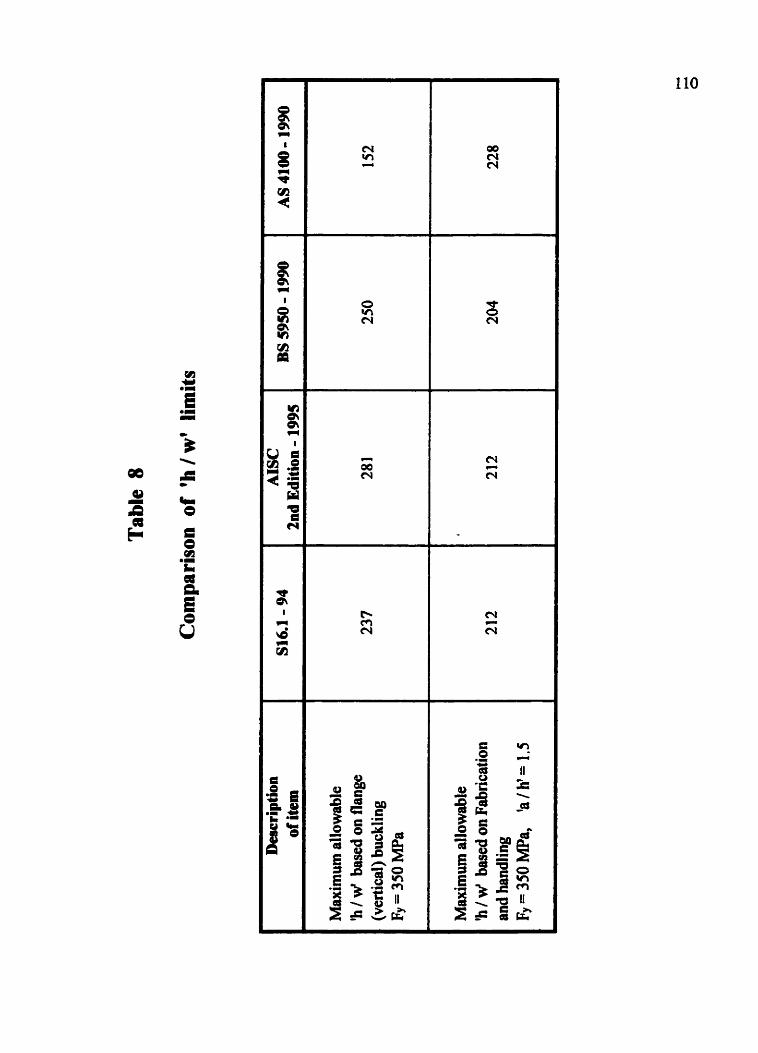

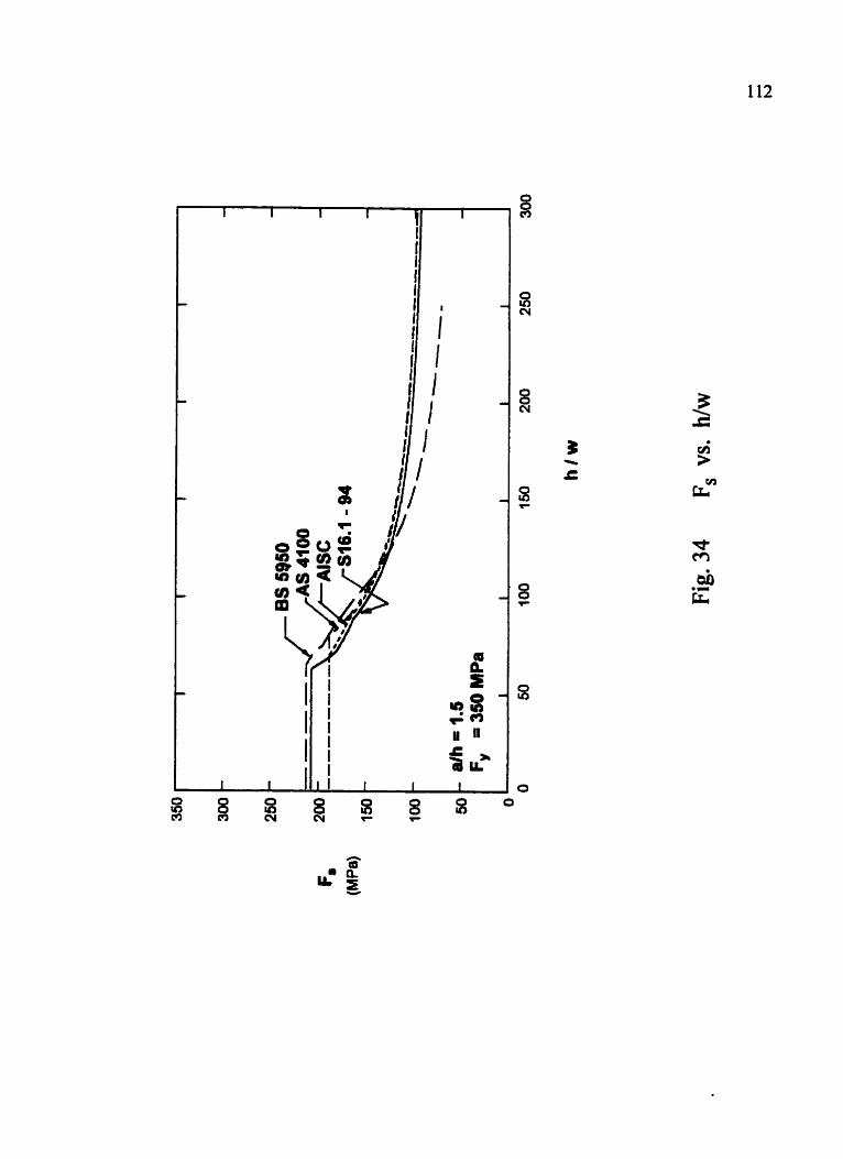

I 1 1 I I
- -
- 3
--- - -
c. -
e- .I
----,--
L a/h 2.6 --* - Fy = 350 MPa
I 1 I I 1 I
Fig. 35 F, vs. h/w
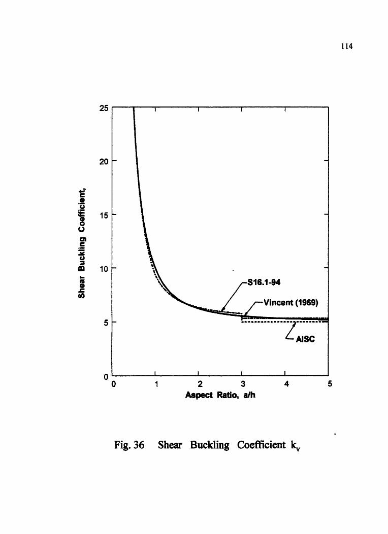
2 3 Aspect Ratio, d h
Fig. 36 Shear Buckling Coefficient
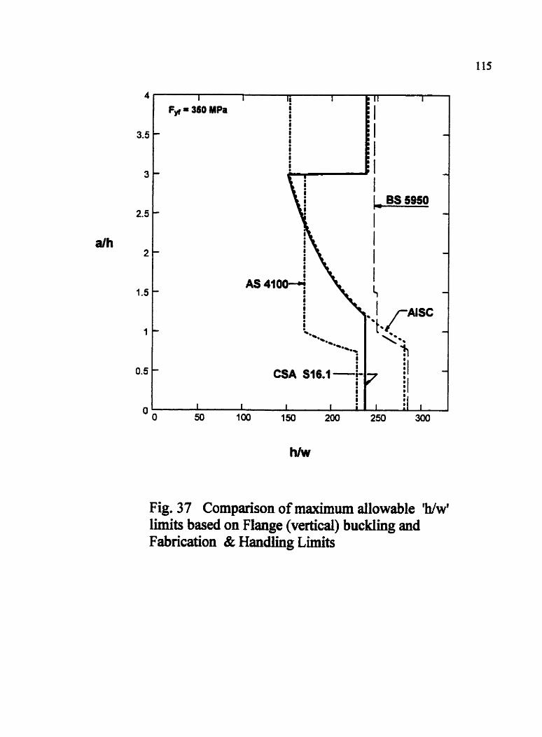
2.5
aih
Fig. 37 Comparison of maximum allowable Ww' limits based on Flange (vertical) buckling and Fabrication & Handling Limits

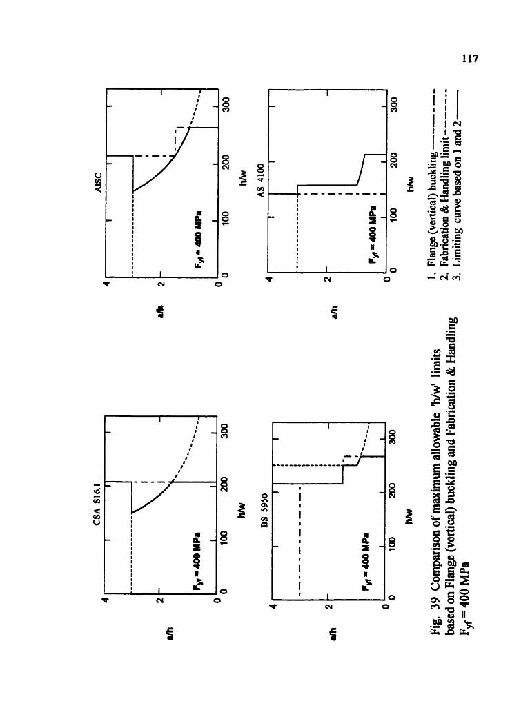
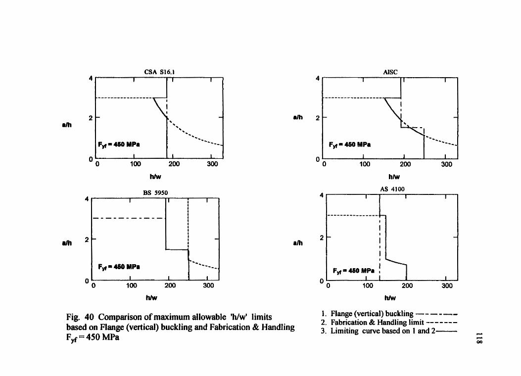
CSA S16.1
Fig. 40 Comparison of maximum allowable Ww' limits based on mange (vertical) buckling and Fabrication & Handling Fyf = 450 MPa
1. Flange (vertical) buckling - - -- - -- 2. Fabrication & Handling limit -- - - -- - 3. Limiting curve based on 1 and 2-

CHAPTER SIX
SUMMARY GND CoNcLUSIONS
6.1 General
The purpose of this dissertation was to review the equations in S 16.1-94 for the
shear design of stiffened plate girders and to suggest modifications to simplify the
standard. It has been found that, of the twenty-six equations that could restrict the design,
only five are likely to have any influence on a typical design. The parametric maps very
clearly show the influence of each shear design equation from the standard. There are
three recommendations for changes to S16.1-94, which would eliminate three equations
fiom the standard and simplify the shear design.
6.2 Conclusions:
62.1 The anchor panel design is likely to be governed by elastic buckling
In a few cases, the vertical buckling or the inelastic buckling equations may govern, as
below:
W Vertical buckling equation - 2 rh
h 83 000
Inelastic buckling equatm w = I vf v 2904 JF,k,
Based on the examples chosen in the study, none of the other equations in S16.1 are
Likely to govern the design,
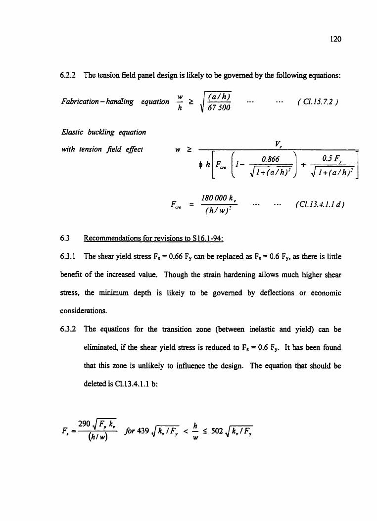
6.2.2 The tension field panel design is likely to be governed by the following equations:
W Fabrication - handling equation - L . . .
h ( CI.15.7.2 )
Elastic buckling equation
with tension field effect
180 000 k, F, = 0 . . 0 . . (CI. 13.4 1.1 d )
( h / w)'
6.3 Recommendations for revisions to S 16.1-94:
6.3.1 The shear yield stress Fs = 0.66 Fy can be replaced as Fs = 0.6 Fy, as there is little
benefit of the increased value. Though the strain hardening allows much higher shear
stress, the minimum depth is likely to be governed by deflections or economic
considerations.
6.3.2 The equations for the transition zone (between inelastic and yield) can be
eliminated, if the shear yield stress is reduced to Fs = 0.6 F,. It has been found
that this zone is ud.ike1y to influence the design. The equation that should be
deleted is C1.13 -4. I. 1 b:

6.3.3 The two equations in C1.13.4.1.1 for the shear buckling coefficient k, can be
replaced with one equation.
Existing equations:
Proposed equation:

REFERENCES
Australian Standard AS 41 00-1 990, "Steel Structures," Standards Australia, The
Crescent, Homebush, NS W 2 140.
Basler, K., 1963 a, "Strength of Plate Girders in Shear," Transactions ASCE, Vol. 128,
Part 11, pp. 683 - 719.
Basler, K., 1963 b, "Strength of Plate Girders Under Combined Bending and Shear,"
Transactions ASCE, Vol. 128, Part a, pp. 720 - 735.
Basier, K. and ThiirLimann, B., 1963, "Strength of Plate Girders in Bending,"
Transactions ASCE, Vol. 128, Part U, pp. 655.
Bleich, F., 1952, "Buckling Strength of Metal Structures, Chapter [I, McGraw-Hill
Companies Inc., New york.
Bradford, M A , 1996, "Improved Shear Strength o f Web Designed in Accordance with
the LRFD SpecificationT" AISC Engineering Journal, Third Quarter, VoI. 33, N0.3,
pp. 95 - 100.
British Standard BS 595k1990: Structural Use of Steelwork in Building, Part I: Code of
Practice for Design in Simple and Continuous Construction: Hot Rolled Section.
CAN/CSA S16.1-94, "Limit States Design of Steel Structures," Canadian Standards
Association, Toronto, Ontario.
CISC Course notes on "Steel Bridge Design, Fabrication and Con~tmction'~, January
1994.
Cooper, PB.,1967, "Strength of Longitudinally Stiffened Plate Girders,'' ASCE Journal
of Structural Division, Vol. 93, No. ST2, pp. 419 - 45 1.
D m , M.N. and Company, Consulting Enginem, Calcutta, [ndia, "Structural Design
Standards"
Fujii, T.,1968, "On an Improved Theory for Dr. Basler's Theory," IABSE 8' Congress,
Final Report, New York, pp. 477 - 487.
Gdambos. T.V., 1998, "Guide to Stability Design Criteria for Metal Structures," 4'
Edition, John Wiley & sons Inc.,
Gdambos, T.V., Lin, FJ., and Johnston, B.G., 1980, "Basic Steel Design," 2"6 Edition,
Prentice-HaU? Inc., New Jersey.

124
Gaylord, E.H., 1963, "Discussion of K. Basler, Strength of Plate Girders in Shear,"
Trans. ASCE. Vol. 128, Part 11, pp. 712 - 719.
Handbook of Steel Construction, 1997, Seventh Edition, Canadian Mtute of Steel
Construction, Willowdale, Ontario.
Herzog, M., 1974, "Ultimate Strength of Plate Girders from Tests," ASCE Journai
Structural Division, 100 (STS), pp. 849 - 864.
Hoglund, T., 1973, "Design of Thin-Plate I Girders in Shear and Bending," Research
Institute, Technological Bulletin. No. 94, Stockholm, Sweden.
IS 800-1964, "Code of Practice for Use of structural steel in General Building
Construction*, Indian Standards Institution, New Delhi, India.
Kulak, G.L., and Gilmor, MI., 1 998, "Limit States Design in Structural Steel ," Canadian
Lnstitute of SteeI Construction.
Lyse, I., and Godfiey, H.J., 1935, "Investigation of Web Buckling in Steel Beams,"
Transaction ASCE, Vol. 100, pp. 675.
MacGinley, TJ-, and Ang, T.C., 1987, c ' S ~ c n u a l Steelwork: Design to Limit State
Theory" 1988, Butterworth & Co (Publishers) Ltd., United Kingdom.

Manual of Steel Constmction LRFD, Vol. I, Second Edition, 1995, American Institute of
Steel Construction, Inc. (AISC).
Marcus, S.H., 1977, "Basics of Structural Steel Design," Reston Publishing Company,
Inc., Virginia
McCorrnac, J.C., 1992, "Structural Steel Design: LRFD Method," Harper & Row
Publishers, New York.
Picard Andre., and Beaulieu Denis., 199 1, "Calcul des Charpentes d'acier," lnstitut
Canadien de la Construction en Acier.
Porter, D.M., Rockey, K.C., and Evans, H.R., 1975, "The Collapse Behavior of Plate
Girders Loaded in Shear," Structural Engineer, Vol. 53, No. 8, pp. 3 13-325.
Rode, H.H., 19 16, "Beitrag zm Theorie der Knickerscheinungen," Wilhelm Engelmarin
Verlag, Leipzig, and Eisenbau, V01.7~19 16, p. 121, 157,210,239, and 296.
Salmon, C.G., and Johnson, J.E., 1996, "Steel Structures - Design and Behavior," 4h
Edition, Harper Collins College Publishers.
126
Selberg, A., 1973, "On the Shear Capacity of Girder Webs," University of Trondheim
Report.
Shedd, T.C., 1934 (Reprint 1957), "Structural Design in Steel," 1 tirn Printing, John Wiley
& Sons, Inc.,
Smith, J.C., 1996, "Structural Steel design - LRFD Approach," John Wiley & sons Inc.,
Taly, Narendra., 1998, "Design of Modern Highway Bridges," The McGraw-Hill
Companies Inc.,
Tioshenko, S.P., and Gere, I.M., 1961, "Theory of Elastic Stability," McGraw-Hill
Companies Inc., New York.
Vincent, G.S., 1969, "Tentative Criteria for Load and Resistance Design of Steel
Bridges," AISI Bulletin No. 15, Washington, DC.
Wagner, H., 193 1, "Flat Sheet Metal Girder with Very Thin Metal Web," NACA Tech.
Memo. Nos. 604,605,606.
Zahn, C.J., 1987, "Plate Girder Design Using LRDFP AISC Engineering Joumai, First
Quarter, Vol. 24, No. 1, pp. 1 1 - 20.

Appendix A
COST ANALYSIS
The following unit prices were assumed in the cost study (based on Waiward Steel
Fabricator Ltb, Edmonton, Alberta as of January 2000) :
(i) Cost of fabrication of plate girder ( flange plates + web plates ) = 1.50 $1 kg
(ii) CostofonestiffenerpIateinstaIIation = 150 E I m height of girder.
Case Study 4:
Original Cost with w = 12.7 mrn and 20 pairs of stiffeners :
Flange plates [email protected]$Ikg =$21990
Web plates = 6853kga 1.5Elkg =$I0280
Stiffeners 40 @ 2.54 rn height =40x2.54m@ 150$Irn =$I5240
Total Cost . . . * ., ... *.. = % 47 510
Alternate 1 with w = 9.53 mm and 16 pairs of stiffeners:
Saving in web weight = 1734 kg@ 1.5 $ 1 kg = $ 2601
Saving in the number of stiffeners = 8 x 2.54 rn @ 150 $ I m = % 3048
Totdsaving ... ... .. . .*. =$5649 =-11%
Alternate 2 with w = 12.7 mm and 10 pairs of stiffeners:
Saving in the number of stiffeners = 20 x 2.54 m @ 150 $ I m = $7620
Total saving ... -.. - *. . . . 4 7 6 2 0 =-16%

Case Study 6:
Original Coa with w = 10 mm and 1 1 pairs of stiffeners:
Flange plates [email protected]$/kg =$ 5676
Web plates =I413 [email protected]/kg =$ 2 120
Stiffeners 22 @ 1.5 rn height =22x1.5m@ 150Slm = $ 4950
Total Cost ... *.. ... .. = % 12 746
Alternate 1 with w = 10 mm and 7 pairs of stiffeners:
Saving in the number of stiffeners = 8 x 1.5 m @ 150 % I rn = $ 1800
Total saving ... ... . .. ... = $ 1800 =- 14%
Alternate 2 with w = 8 mm and 10 pairs of stiffeners:
Saving in web weight =283 kg@ 1.5$/kg = $425
Saving in the number of stiffeners = 2 x 1.5 m @ 150 $ I m = $450
Total saving ... ... ... ... 4 8 7 5 =-7%
Case Study 7:
Original Cost with w = 16 mm and 1 1 pairs of stiffeners:
Flange plates [email protected]$/kg =$ 7178
W e b plates [email protected] =$ 3392
Stiffeners 22 @ 1.5 m height =22xI.5rn@150$/m =$ 4950
Totalcost .,, ... ... - -. =$ IS 520
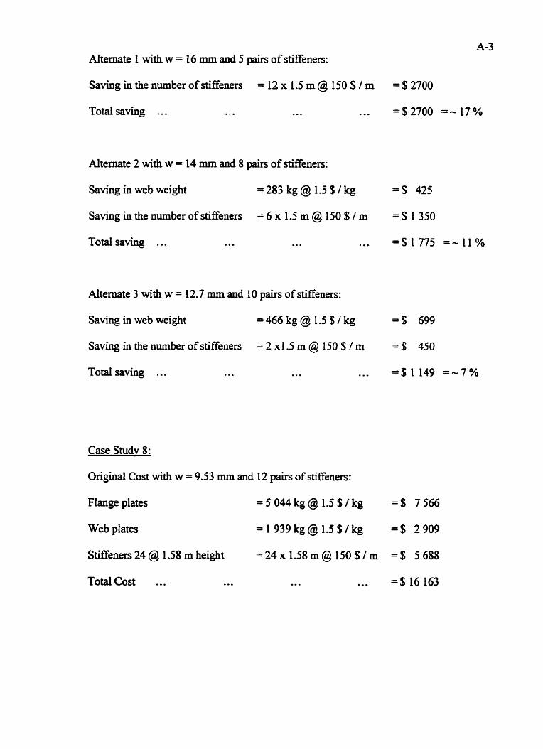
Alternate 1 with w = 16 mm and 5 pairs of stiffeners:
Saving in the number of stiffeners = 12 x 1.5 m @ 150 $ 1 m = $2700
Total saving . .. .. . ... ... =$2700 =- 17%
Altemate 2 with w = 14 mm and 8 pairs of stiffeners:
Saving in web weight =283 kg@ l .S$/kg =$ 425
Saving in the number of stiffeners = 6 x 1.5 m @ 150 $1 m = $ 1 350
Total saving ... . . . ... ... =% 1775 = -11%
Alternate 3 with w = 12.7 mm and 10 pairs of stiffeners:
Saving in web weight =466 kg @ 1.5 $ /kg =$ 699
Saving in the number of stiffeners = 2 x 1.5 m @ 150 S / m = $ 450
Totd saving ... . .. .* . ..- = % I 149 =-7%
Case Studv 8:
Original Cost with w = 9.53 mm and 12 pairs of stiffeners:
Flange plates = 5 044 kg@ 1.5 $/kg =$ 7 566
Web plates = 1 9 3 9 k g @ l . S $ / k g =$ 2909
Stiffeners 24 @ 1.58 m height =24xI.58m@ 150S/rn =$ 5688
Totalcost ... . - . . . . - - . = $ I 6 163

Alternate 1 with w = 9.53 mm and 10 pairs of stiffeners:
Saving in the number of stiffeners = 4 x 1.58 m @ 150 $ I rn = S 945
Total saving ... . .. ... ... 4 9 4 5 = - 6 %
Alternate 2 with w = 8 mrn and 12 pairs of stiffeners:
Saving in web weight =311 k g @ 1 5 f / k g = $ 467
Total saving ... . . . ... . .. =$ 467 = - 3 %
Case Study 9:
Original Cost with w = 14 mrn and 7 pairs of stiffeners:
Flange plates [email protected]%Ikg = $ I2491
Web plates =5275 kg@ 1.5 $/kg =% 7913
Stiffeners 14 @ 2.4 rn height =14x2.4m@ 150SIm = $ 5040
Totalcost ... ... ... g . . = $ 25444
Alternate 2 with w = 12 mm and 8 pairs of stiffeners:
Saving in web weight =754 kg @ l .S$ /kg = $ I131
Cost increase for one pair of stiffener- 2 x 2.4 m @ 150 $ I m = $ 720 (-)
Total saving . . . ... * . . . . . = $ 411 =-2%
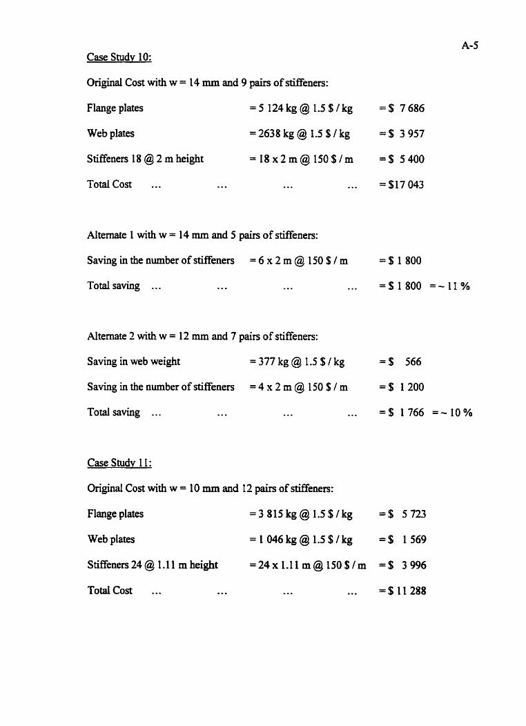
Case Study 10:
Original Cost with w = 14 mm and 9 pairs of stiffeners:
Flange plates = 5 124kg@ 1.5s Ikg = % 7686
Web plates =2638 kg@ 1.5SIkg =$ 3957
Stiffeners 18 @ 2 m height = 1 8 x Z m @ 1 5 0 $ / m = $ 5 4 0 0
... Totalcost ... ... ..- = $17 043
Alternate 1 with w = 14 mrn and 5 pairs of stiffeners:
Saving in the number of stiffeners = 6 x 2 m @ 150 $ I m = % 1 800
Total saving ... ... ... ... = $ I800 =- 1 1 %
Alternate 2 with w = 12 rnm and 7 pain of stiffeners:
Saving in web weight =377kg@ 1.5SIkg = $ 566
Saving in the number of stiffeners = 4 x 2 m @ 150 $ I m = $ 1 200
... Total saving . .. . .. ... = $ 1766 = - l o %
Case Studv 1 I :
Original Cost with w = 10 mm and 12 pairs of Meners:
Flange plates = 3 [email protected]$/kg =$ 5723
Web plates =1046kg@15$/kg =$ 1569
Stiffeners 24 @ 1.1 1 rn height =24x 1-11 m@ I50EIm =$ 3 996
Totalcost .., -.- ... . . = $ I 1 288

Alternate 1 with w = 10 mm and 10 pairs of stiffeners:
Saving in the number of stiffeners = 4 x 1.1 1 m Q 150 $ I m = $666
Total saving ... . .. . .. ... =$666 = - 6 %
Case Study 12:
Original Cost with w = 10 mrn and 7 pairs of stiffeners:
Flange plates = 2983 kg@ l . S $ I k g = $ 4475
Web plates = 1670 kg@ 1.5SIkg = $ 2505
Stiffeners 14 @ 1.4 rn height = 14 x 1.4 m @ 150 $ I m = $ 2940
Totalcost ... -.. .-. ,.- = $ 9 920
Alternate 2 with w = 8 mm and 8 pairs of stiffeners:
Saving in web weight =334 kg@ 1.5$Ikg = $501
Cost increase for one pair of stiEener= 2 x 1 -4 m @ 1 50 $ I m = $420 (-)
Total saving . . . .- *.. . . . = $ 81 =-0.8%
Optimization of airder depth for Case 12:
i) 8 mrn web thickness and f 900 mm depth with 9 air of stiffeners
Flange plates [email protected]/kg =$ 2900
Web plates [email protected]$/kg =$ 2870
Stiffeners 1 8 @ 1 -9 m height =18x1.9m@150$/m =$ 5130
Total Cost ,-, -.. ... * o - = $10 900
Additional Cost ., C =$10900-9920 ,,. --- =$980-10%
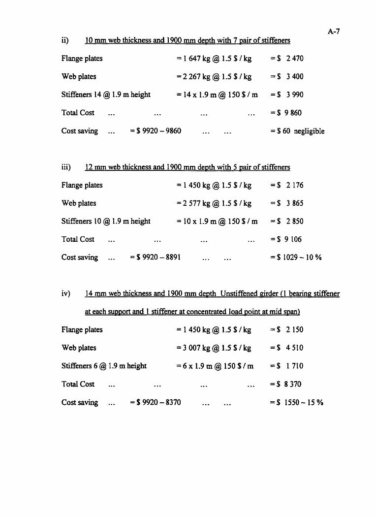
ii) 10 mm web thickness and 1900 mm depth with 7 pair of stiffeners
Flange plates [email protected]$lkg =$ 2470
Web plates [email protected]$1kg =$ 3400
Stiffeners 14 @ 1 -9 rn height =14x1.9rn@ 150Slm = $ 3990
Totalcost ... ... ... *. . = $ 9860
Cost saving ... = $9920 - 9860 . . ... = S 60 negligible
iii) 12 mm web thickness and 1900 mm de~th with 5 air of stiffeners
Flange plates [email protected]$lkg 4 2 1 7 6
Web plates [email protected]$Ikg = $ 3865
Stiffeners 10 @ 1.9 m height =lox 1.9m@ 150SIrn = $ 2850
TotaI Cost ... ... ..+ ... = $ 9 106
Cost saving ... = $9920 - 8891 *. . ... =% 1029-10%
iv) 14 mm web thickness and 1900 rnm de~th Unstiffened girder I1 bearinn stiffener
at each m ~ o r t and 1 stiffener at concentrated load mint at mid man)
Flange plates [email protected]$/kg = $ 2150
Web plates [email protected] =$ 4510
Stiffeners 6 @ 1.9 m height =6x1.9m@ 150$/m =$ 1710
Total Cost ... - D o .. - .*. =$ 8370
Costsaving ... = $9920 - 8370 W o o . . o =$ 1550- 15%