strong coupling cavity qed with gate-defined double quantum dots enabled...
TRANSCRIPT

Strong Coupling Cavity QED with Gate-Defined Double Quantum Dots Enabledby a High Impedance Resonator
A. Stockklauser,* P. Scarlino,† J. V. Koski, S. Gasparinetti, C. K. Andersen, C. Reichl, W. Wegscheider,T. Ihn, K. Ensslin, and A. Wallraff‡
Department of Physics, ETH Zurich, CH-8093 Zurich, Switzerland(Received 16 January 2017; revised manuscript received 17 February 2017; published 9 March 2017)
The strong coupling limit of cavity quantum electrodynamics (QED) implies the capability of amatterlike quantum system to coherently transform an individual excitation into a single photon within aresonant structure. This not only enables essential processes required for quantum information processingbut also allows for fundamental studies of matter-light interaction. In this work, we demonstrate strongcoupling between the charge degree of freedom in a gate-defined GaAs double quantum dot (DQD) and afrequency-tunable high impedance resonator realized using an array of superconducting quantuminterference devices. In the resonant regime, we resolve the vacuum Rabi mode splitting of size 2g=2π ¼238 MHz at a resonator linewidth κ=2π ¼ 12 MHz and a DQD charge qubit decoherence rate of γ2=2π ¼40 MHz extracted independently from microwave spectroscopy in the dispersive regime. Our measure-ments indicate a viable path towards using circuit-based cavity QED for quantum information processing insemiconductor nanostructures.
DOI: 10.1103/PhysRevX.7.011030 Subject Areas: Mesoscopics, Quantum Physics
In the strong coupling limit, cavity QED realizes thecoherent exchange of a single quantum of energy between anonlinear quantum system with two or more energy levels,e.g., a qubit, and a single mode of a high quality cavitycapable of storing individual photons [1]. The distinguish-ing feature of strong coupling is a coherent coupling rate g,determined by the product of the dipole moment of themultilevel system and the vacuum field of the cavity, whichexceeds both the cavity mode linewidth κ, determining thephoton lifetime, and the qubit linewidth γ2 ¼ γ1=2þ γφ,set by its energy relaxation and pure dephasing rates, γ1 andγφ, respectively.The strong coupling limit of cavityQEDhas been reached
with a multitude of physical systems including alkali atoms[2], Rydberg atoms [3], superconducting circuits [4,5], andoptical transitions in semiconductor quantum dots [6,7]. Ofparticular interest is the use of this concept in quantuminformation processing with superconducting circuits,where it is known as circuit QED [4,8,9].Motivated by the ability to suppress the spontaneous
emission of qubits beyond the free space limit [10], toperform quantum nondemolition (QND) qubit read-out
[11,12], to couple distant qubits through microwave pho-tons coherently [13,14], and to convert quantum informa-tion stored in stationary qubits to photons [15,16], researchtowards reaching the strong coupling limit of cavity QED ispursued for the charge and spin degrees of freedom insemiconductor nanostructures [17–22]. Recently, in paral-lel with the work discussed here, independent efforts toreach this goal have come to fruition with gate-definedDQDs in silicon [23] and carbon nanotubes [24].The essence of our approach to reach the strong coupling
limit with individual electronic charges in GaAs DQDs isrooted in the enhancement of the electric component of thevacuum fluctuations ∝
ffiffiffiffiffi
Zrp
[25] by increasing the reso-nator impedance Zr beyond the typical 50 Ω of a standardcoplanar waveguide. We have realized a frequency-tunablemicrowave resonator with impedance Zr ¼
ffiffiffiffiffiffiffiffiffiffiffiffiffi
Lr=Cr
p
∼1.8 kΩ using the large inductance Lr ∼ 50 nH of aSQUID array [26–28] combined with a small stray capaci-tance Cr ∼ 15 fF. Its resonance frequency, and thus also itsimpedance, is tunable by applying a small magnetic fieldusing a mm-sized coil mounted on the sample holder. Thefrequency tunability of the resonator is particularly usefulin this context, as it allows for the systematic study of itsinteraction with semiconductor nanostructures withoutchanging their electrical bias conditions.The resonator, with a small footprint of 300 × 120 μm2
[Figs. 1(a) and 1(b)], is fabricated using standard electron-beam lithography and shadow evaporation of aluminum(Al) onto a GaAs heterostructure. The embedded two-dimensional electron gas (2DEG) has been etched awayeverywhere but in a small mesa region hosting the DQD.
*[email protected]†[email protected]‡[email protected]
Published by the American Physical Society under the terms ofthe Creative Commons Attribution 4.0 International license.Further distribution of this work must maintain attribution tothe author(s) and the published article’s title, journal citation,and DOI.
PHYSICAL REVIEW X 7, 011030 (2017)
2160-3308=17=7(1)=011030(6) 011030-1 Published by the American Physical Society

The array, composed of 32 SQUIDs [Fig. 1(d)], is groundedat one end and terminated in a small island at the other endto which a single coplanar drive line is capacitivelycoupled. A gate line extends from the island and formsone of the plunger gates of the double quantum dot (orange)[Fig. 1(c)].The double quantum dot is formed in the mesa structure
using gold (Au) top gates [yellow in Figs. 1(a)–1(c)]controlling the tunnel coupling of the DQD to the sourceand drain leads (blue) as well as the interdot tunnelcoupling t. The left and right side gates (LSG, RSG)control the on-site electrostatic energies of each of the twodots, while the plunger gates are not biased in the experi-ment. An additional gate and pair of leads can beconfigured as a quantum point contact for charge detection.The microwave response of the system is probed inreflection [Fig. 1(e)] using standard circuit QED hetero-dyne detection techniques [4,18].We show that the resonance frequency of the SQUID
array resonator can be tuned from a maximum value ofνr ∼ 6.0 GHz to well below 4.5 GHz (which is the lowercutoff frequency of our detection electronics) in measure-ments of its reflectance jS11ðνpÞj as a function of appliedmagnetic fluxΦm and probe frequency νp [Fig. 2(a)]. Fromthese data, we extract the characteristic circuit parametersof the resonator and find that its impedance changes from
Zr ∼ 1.3 kΩ to 1.8 kΩ in this frequency range. Frommeasurements of the SQUID array resistance at roomtemperature, we estimate a critical current of about210 nA per SQUID. The microwave drives applied tothe resonator in the experiments discussed here createphoton occupations on the order of one or below, resultingin currents in the resonator far below the critical ones. Inthis regime, the device has a linear response. At higherdrive strength, the nonlinearity of the device is observedand may be characterized in spectroscopic measurements[29]. With the DQD well detuned from the resonator biasedat νr ¼ 5.02 GHz, we determine its internal loss rate, itsexternal coupling rate to the input line, and the totallinewidth ðκint; κext; κÞ=ð2πÞ ∼ ð10.0; 2.3; 12.3Þ MHz [30].We configure the double quantum dot and determine
its characteristic properties by extracting the amplitudeand phase change of a coherent tone reflected off theresonator at frequency νp using a measurement of thereflection coefficient S11ðνpÞ in response to changes ofthe potentials applied to the gate electrodes forming thedouble quantum dot. Using this by-now well-establishedtechnique [17–19], we record characteristic hexagonalcharge stability diagrams [Fig. 2(b)] from which weextract the DQD charging energy of 580 GHz andestimate the number of charges in each dot to be ofthe order of 10 electrons [18,31].
(a)
(c) (d) (e)
(b)
FIG. 1. Sample and simplified circuit diagram. (a) False-color optical micrograph of a representative device indicating the substrate(dark gray), the superconducting structures (light gray), the gold top gates (yellow) forming the DQD, and its source and drain leads andcontacts (blue). (b) Optical micrograph displaying a SQUID array resonator (light gray) and its coupling gate to the DQD and the DQDbiasing structures (yellow). (c) Electron micrograph of the DQD showing its electrostatic top gates (yellow) and the plunger gate coupledto the resonator (orange). (d) Electron micrograph of three SQUID loops (dark grey) in the array deposited on the etched GaAsheterostructure (light gray). (e) Circuit diagram schematically displaying the DQD (source contact labeled S, drain contact labeled D,and coupling capacitance CPG to the resonator) and essential components in the microwave detection chain (circulator, amplifier) usedfor performing reflectance measurements of the device. Boxes with crosses and rectangles indicate Josephson and normal tunneljunctions, respectively.
A. STOCKKLAUSER et al. PHYS. REV. X 7, 011030 (2017)
011030-2
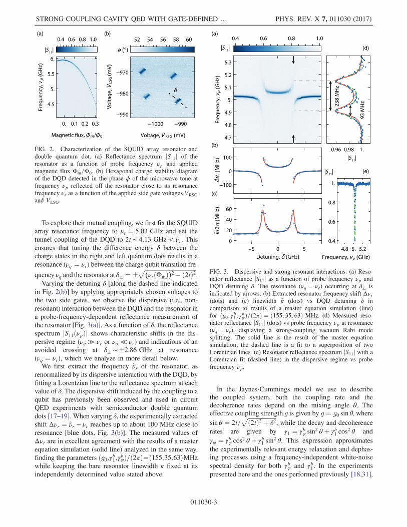
To explore their mutual coupling, we first fix the SQUIDarray resonance frequency to νr ¼ 5.03 GHz and set thetunnel coupling of the DQD to 2t ∼ 4.13 GHz < νr. Thisensures that tuning the difference energy δ between thecharge states in the right and left quantum dots results in aresonance (νq ¼ νr) between the charge qubit transition fre-
quency νq and the resonator at δ� ¼ �ffiffiffiffiffiffiffiffiffiffiffiffiffiffiffiffiffiffiffiffiffiffiffiffiffiffiffiffiffiffiffiffiffiffiffiffi
(νrðΦmÞ)2 − ð2tÞ2p
.Varying the detuning δ [along the dashed line indicated
in Fig. 2(b)] by applying appropriately chosen voltages tothe two side gates, we observe the dispersive (i.e., non-resonant) interaction between the DQD and the resonator ina probe-frequency-dependent reflectance measurement ofthe resonator [Fig. 3(a)]. As a function of δ, the reflectancespectrum jS11ðνpÞj shows characteristic shifts in the dis-persive regime (νq ≫ νr or νq ≪ νr) and indications of anavoided crossing at δ� ∼�2.86 GHz at resonance(νq ¼ νr), which we analyze in more detail below.We first extract the frequency ~νr of the resonator, as
renormalized by its dispersive interaction with the DQD, byfitting a Lorentzian line to the reflectance spectrum at eachvalue of δ. The dispersive shift induced by the coupling to aqubit has previously been observed and used in circuitQED experiments with semiconductor double quantumdots [17–19]. When varying δ, the experimentally extractedshift Δνr ¼ ~νr − νr reaches up to about 100 MHz close toresonance [blue dots, Fig. 3(b)]. The measured values ofΔνr are in excellent agreement with the results of a masterequation simulation (solid line) analyzed in the same way,finding the parameters ðg0;γb1;γbφÞ=ð2πÞ¼ð155;35;63ÞMHzwhile keeping the bare resonator linewidth κ fixed at itsindependently determined value stated above.
In the Jaynes-Cummings model we use to describethe coupled system, both the coupling rate and thedecoherence rates depend on the mixing angle θ. Theeffective coupling strength g is given by g ¼ g0 sin θ, wheresin θ ¼ 2t=
ffiffiffiffiffiffiffiffiffiffiffiffiffiffiffiffiffiffiffiffi
ð2tÞ2 þ δ2p
, while the decay and decoherencerates are given by γ1 ¼ γbφ sin2 θ þ γb1 cos
2 θ andγφ ¼ γbφ cos2 θ þ γb1 sin
2 θ. This expression approximatesthe experimentally relevant energy relaxation and dephas-ing processes using a frequency-independent white-noisespectral density for both γbφ and γb1 . In the experimentspresented here and the ones performed previously [18,31],
(a)
(d)
(e)
(b)
(c)
FIG. 3. Dispersive and strong resonant interactions. (a) Reso-nator reflectance jS11j as a function of probe frequency νp andDQD detuning δ. The resonance (νq ¼ νr) occurring at δ� isindicated by arrows. (b) Extracted resonator frequency shift Δνr(dots) and (c) linewidth ~κ (dots) vs DQD detuning δ incomparison to results of a master equation simulation (line)for ðg0; γb1 ; γbφÞ=ð2πÞ ¼ ð155; 35; 63Þ MHz. (d) Measured reso-nator reflectance jS11j (dots) vs probe frequency νp at resonance(νq ¼ νr), displaying a strong-coupling vacuum Rabi modesplitting. The solid line is the result of the master equationsimulation; the dashed line is a fit to a superposition of twoLorentzian lines. (e) Resonator reflectance spectrum jS11j with aLorentzian fit (dashed line) in the dispersive regime vs probefrequency νp.
(b)(a)
FIG. 2. Characterization of the SQUID array resonator anddouble quantum dot. (a) Reflectance spectrum jS11j of theresonator as a function of probe frequency νp and appliedmagnetic flux Φm=Φ0. (b) Hexagonal charge stability diagramof the DQD detected in the phase ϕ of the microwave tone atfrequency νp reflected off the resonator close to its resonancefrequency νr as a function of the applied side gate voltages VRSGand VLSG.
STRONG COUPLING CAVITY QED WITH GATE-DEFINED … PHYS. REV. X 7, 011030 (2017)
011030-3

we accurately model the observed linewidths within theexperimentally explored frequency range using thisapproximation.Using the set of parameters that models the dispersive
frequency shift, we also find excellent agreement with theeffective linewidth ~κ of the resonator as renormalized by thehybridization with the DQD charge qubit. Detuned fromthe quantum dot, the resonator displays the bare linewidthκ. When approaching resonance, it is increased by morethan a factor of 4 because of the interaction with the qubitwith significantly larger linewidth γ2 ≫ κ. Near resonanceνq ∼ νr, the resonator reflectance does not display a singleLorentzian line shape in probe frequency but develops twowell-resolved spectral lines.Tuning the DQD into resonance with the resonator
(νq ¼ νr), indicated by arrows in Fig. 3(a), we observe aclear vacuum Rabi mode splitting (blue dots) in thereflectance spectrum of the resonator [Fig. 3(d)]. A fit(dashed green line) of the spectrum to a superposition oftwoLorentzian lines yields a splitting of 2g=2π ∼ 238 MHz,with an effective linewidth of 93 MHz. The vacuum Rabimode splitting is found to be in good agreement with thespectrum evaluated from the master equation simulation(red solid line) with the parameters ðg0; γb1; γbφÞ=ð2πÞ ¼ð155; 35; 63Þ MHz, which is consistent with the analysis
of the dispersive frequency shift discussed above. We notethat the small amplitude of the signal in reflection is a directconsequence of the fact that the qubit decoherence rate γ2 issignificantly larger than the resonator decay rate κ, anobservation that is also reproduced in the theoretical analysisof the data.Furthermore, we analyze the spectroscopic properties of
the DQD charge qubit in two complementary measure-ments. First, we make use of the frequency tunability of thehigh impedance SQUID array resonator by applying asmall magnetic fluxΦm to its SQUID loops and keeping theDQD charge qubit at a fixed tunnel coupling 2t. At a set offrequencies fνrðΦmÞg, we observe resonator spectra char-acteristic for its dispersive and resonant interaction with thequbit [Fig. 4(a)]. The resonances (νq ¼ νr) occurring at δ�for the set of values fνrðΦmÞg (red data points) are in goodagreement with the expected dependence of the qubitenergy levels on δ [see dashed line in Fig. 4(a)]. We notethat at each resonance [νq ¼ νrðΦmÞ] an avoided crossingdisplaying a vacuum Rabi mode splitting is observed.We also perform qubit spectroscopy by probing the
amplitude and phase of the resonator reflectance at fixedmeasurement frequency νp ¼ 5.947 GHz while applyingan additional spectroscopy microwave tone at frequency νsto the resonator. When the spectroscopy tone is resonant
(a) (b) (c)
(d)
(e)
FIG. 4. DQD charge qubit spectroscopy. (a) Resonator reflectance spectra jS11j as a function of probe frequency νp and DQD detuningδ for a set of four independent measurements taken at νrðΦmÞ ≈ f4.5; 5.0; 5.5; 5.9g GHz. Red points indicate resonance (νq ¼ νr)extracted from the data. The dashed line indicates the calculated transition frequency of the charge qubit. (b) Amplitude A of fixedfrequency measurement tone νp ¼ 5.947 GHz reflected from the resonator vs qubit spectroscopy frequency νs and qubit detuning δ. Thedashed line indicates the expected qubit resonance frequency for 2t ¼ 4.13 GHz. (c) Qubit line shapes AðνsÞ (dots) measured at δ ¼ 0[arrows in (b)] for drive strengths Ps ¼ f−5;−10;−15g dBm at the generator and fits to Lorentzian lines (on a linear background),extracting the full width at half maximum (FWHM) of the line δνq. Probe frequency νp ¼ 5.022 GHz, and probe power Pp ¼ −35 dBmat the generator. (d) Extracted qubit linewidth δν2q (blue dots) vs spectroscopy drive power Ps with linear fit (red solid line). (e) Saturationof qubit population with spectroscopy drive power Ps.
A. STOCKKLAUSER et al. PHYS. REV. X 7, 011030 (2017)
011030-4

with the qubit transition frequency (νs ¼ νq), the qubit isexcited from its ground state jgi to a mixture betweenground and excited states jei. This mixed state changes theresonance frequency ~νr of the resonator by dispersivecoupling, resulting in a detectable change of the amplitudeA (and also of phase ϕr, not shown) of the microwave tonereflected at frequency νp [Fig. 4(b)]. This technique hasbeen pioneered for superconducting qubits [11,12], whereit is widely used. Varying both the qubit detuning δ and thespectroscopy frequency νs, we map out the spectrum of thequbit [dashed line, Fig. 4(b)] and determine its tunnelcoupling 2t ¼ 4.13 GHz.Using this technique, we are not only able to accurately
determine the transition frequency νq of the DQD chargequbit but also its line shape, shown for three drive powersPs in Fig. 4(c). The observed line shape depends on thequbit intrinsic linewidth, as set by its dephasing time T⋆
2 ,and on the strength of the applied microwave drive Ps,which broadens the line proportional to its amplitude. In thelimit of weak driving (Ps → 0), the spectroscopic linewidthδνq ∼ 80 MHz (FWHM) is determined by the dephasingtime T⋆
2 ∼ 4.0 ns of the DQD qubit as extracted from alinear fit to the data in Fig. 4(d). This corresponds to a qubitdecoherence rate γ2=2π ¼ 40 MHz. Increasing the drivestrength Ps, we observe the qubit transition and thus alsothe resonator response to approach saturation [Fig. 4(e)].Aspects in which the current device may still be
optimized are the coherence properties of both theSQUID array resonator and the DQD. In characterizationmeasurements of test samples, we found the observedinternal loss rate κint ∼ 10 MHz of the resonator to bedominated by residual coupling to the resistive and radi-ative loss channels provided by the normal metal leads ofthe DQD. In future device iterations, we plan to mitigateboth effects by using superconducting Al gates and on-chiplow pass filters [23,32]. Both measures may also improvethe coherence properties of the DQD [23]. In previousmeasurements with coplanar waveguide resonators, wehave not found a strong dependence of the DQD coherenceon the number of charges down to the single electronregime [31]. In GaAs devices, the charge relaxation ratemay ultimately be limited by the electron-phonon couplingin the piezoelectric host material [33]. This effect may bereduced by using materials such as silicon [34], whichwould also allow us to study the spin dynamics ofindividual electrons in an environment less prone todecoherence due to coupling to nuclear spins. To studyspin dynamics at finite applied magnetic fields, it may alsobe interesting to explore alternative approaches to highimpedance resonators such as the ones based on high-kinetic-inductance thin-film resonators [35].The data presented in this manuscript indicate that the
strong coupling limit of a semiconductor charge qubitformed in a double quantum dot coupled to a microwavephoton has been realized. This result is achieved by the use
of a high impedance SQUID array resonator increasing thecoupling strength by a factor of 6 relative to couplingschemes using conventional 50-Ω resonators. Thisapproach is universally applicable to any circuit QEDapplication striving to maximize the coupling to the chargedegree of freedom. The realization of strong coupling inthis semiconductor circuit QED device also enabled us toperform spectroscopy of the DQD qubit in the dispersiveregime to evaluate its line shape in dependence on themicrowave drive power, indicating the possibility oftemporally resolving the charge dynamics. These resultscarry promise to further advance quantum informationprocessing efforts based on semiconductor charge and spinqubits using circuit QED approaches, e.g., to perform QNDread-out and to realize coupling between distant qubitsthrough microwave photons.
We acknowledge contributions by Michele Collodo,Andreas Landig, Ville Maisi, and Anton Potočnik. Wethank Alexandre Blais for valuable feedback on the manu-script. This work was supported by the Swiss NationalScience Foundation through the National Center ofCompetence in Research (NCCR) Quantum Science andTechnology and by Eidgenössische Technische HochschuleZürich.A. S. and P. S. contributed equally to this work.
[1] S. Haroche and J.-M. Raimond, Exploring the Quantum:Atoms, Cavities, and Photons (Oxford University Press,New York, 2006).
[2] R. J. Thompson, G. Rempe, and H. J. Kimble, Observationof Normal-Mode Splitting for an Atom in an Optical Cavity,Phys. Rev. Lett. 68, 1132 (1992).
[3] M. Brune, F. Schmidt-Kaler, A. Maali, J. Dreyer, E. Hagley,J. M. Raimond, and S. Haroche, Quantum Rabi Oscillation:A Direct Test of Field Quantization in a Cavity, Phys. Rev.Lett. 76, 1800 (1996).
[4] A. Wallraff, D. I. Schuster, A. Blais, L. Frunzio, R.-S.Huang, J. Majer, S. Kumar, S. M. Girvin, and R. J.Schoelkopf, Strong Coupling of a Single Photon to aSuperconducting Qubit Using Circuit QuantumElectrodynamics, Nature (London) 431, 162 (2004).
[5] I. Chiorescu, P. Bertet, K. Semba, Y. Nakamura, C. J. P. M.Harmans, and J. E. Mooij, Coherent Dynamics of a FluxQubit Coupled to a Harmonic Oscillator, Nature (London)431, 159 (2004).
[6] T. Yoshie, A. Scherer, J. Hendrickson, G. Khitrova, H. M.Gibbs, G. Rupper, C. Ell, O. B. Shchekin, and D. G. Deppe,Vacuum Rabi Splitting with a Single Quantum Dot in aPhotonic Crystal Nanocavity, Nature (London) 432, 200(2004).
[7] J. P. Reithmaier, G. Sek, A. Loffler, C. Hofmann, S. Kuhn,S. Reitzenstein, L. V. Keldysh, V. D. Kulakovskii, T. L.Reinecke, and A. Forchel, Strong Coupling in a SingleQuantum Dot-Semiconductor Microcavity System, Nature(London) 432, 197 (2004).
STRONG COUPLING CAVITY QED WITH GATE-DEFINED … PHYS. REV. X 7, 011030 (2017)
011030-5

[8] A. Blais, R.-S. Huang, A. Wallraff, S. M. Girvin, and R. J.Schoelkopf, Cavity Quantum Electrodynamics for Super-conducting Electrical Circuits: An Architecture for Quan-tum Computation, Phys. Rev. A 69, 062320 (2004).
[9] R. J. Schoelkopf and S. M. Girvin, Wiring up QuantumSystems, Nature (London) 451, 664 (2008).
[10] A. A. Houck, J. A. Schreier, B. R. Johnson, J. M. Chow,Jens Koch, J. M. Gambetta, D. I. Schuster, L. Frunzio, M. H.Devoret, S. M. Girvin, and R. J. Schoelkopf, Controlling theSpontaneous Emission of a Superconducting TransmonQubit, Phys. Rev. Lett. 101, 080502 (2008).
[11] D. I. Schuster, A. Wallraff, A. Blais, L. Frunzio, R.-S.Huang, J. Majer, S. M. Girvin, and R. J. Schoelkopf,AC Stark Shift and Dephasing of a Superconducting QubitStrongly Coupled to a Cavity Field, Phys. Rev. Lett. 94,123602 (2005).
[12] A. Wallraff, D. I. Schuster, A. Blais, L. Frunzio, J. Majer,S. M. Girvin, and R. J. Schoelkopf, Approaching UnitVisibility for Control of a Superconducting Qubit withDispersive Readout, Phys. Rev. Lett. 95, 060501 (2005).
[13] J. Majer, J. M. Chow, J. M. Gambetta, J. Koch, B. R.Johnson, J. A. Schreier, L. Frunzio, D. I. Schuster, A. A.Houck, A. Wallraff et al., Coupling Superconducting Qubitsvia a Cavity Bus, Nature (London) 449, 443 (2007).
[14] M. A. Sillanpää, J. I. Park, and R.W. Simmonds, CoherentQuantum State Storage and Transfer Between Two PhaseQubits via a Resonant Cavity, Nature (London) 449, 438(2007).
[15] A. A. Houck, D. I. Schuster, J. M. Gambetta, J. A. Schreier,B. R. Johnson, J. M. Chow, L. Frunzio, J. Majer, M. H.Devoret, S. M. Girvin, and R. J. Schoelkopf, GeneratingSingle Microwave Photons in a Circuit, Nature (London)449, 328 (2007).
[16] C. Eichler, C. Lang, J. M. Fink, J. Govenius, S. Filipp, andA. Wallraff,Observation of Entanglement Between ItinerantMicrowave Photons and a Superconducting Qubit, Phys.Rev. Lett. 109, 240501 (2012).
[17] M. R. Delbecq, V. Schmitt, F. D. Parmentier, N. Roch, J. J.Viennot, G. Fève, B. Huard, C. Mora, A. Cottet, and T.Kontos, Coupling a Quantum Dot, Fermionic Leads, and aMicrowave Cavity on a Chip, Phys. Rev. Lett. 107, 256804(2011).
[18] T. Frey, P. J. Leek, M. Beck, A. Blais, T. Ihn, K. Ensslin,and A. Wallraff, Dipole Coupling of a Double Quantum Dotto a Microwave Resonator, Phys. Rev. Lett. 108, 046807(2012).
[19] K. D. Petersson, L. W. McFaul, M. D. Schroer, M. Jung,J. M. Taylor, A. A. Houck, and J. R. Petta, Circuit QuantumElectrodynamics with a Spin Qubit, Nature (London) 490,380 (2012).
[20] H. Toida, T. Nakajima, and S. Komiyama, Vacuum RabiSplitting in a Semiconductor Circuit QED System, Phys.Rev. Lett. 110, 066802 (2013).
[21] A. Wallraff, A. Stockklauser, T. Ihn, J. R. Petta, andA. Blais, Comment on “Vacuum Rabi Splitting in a
Semiconductor Circuit QED System”, Phys. Rev. Lett.111, 249701 (2013).
[22] J. J. Viennot, M. C. Dartiailh, A. Cottet, and T. Kontos,Coherent Coupling of a Single Spin to Microwave CavityPhotons, Science 349, 408 (2015).
[23] X. Mi, J. V. Cady, D. M. Zajac, P. W. Deelman, and J. R.Petta, Strong Coupling of a Single Electron in Silicon to aMicrowave Photon, Science 355, 156 (2017).
[24] L. E. Bruhat, T. Cubaynes, J. J. Viennot, M. C. Dartiailh, M.M. Desjardins, A. Cottet, and T. Kontos, Strong CouplingBetween an Electron in a Quantum Dot Circuit and aPhoton in a Cavity, arXiv:1612.05214.
[25] M. H. Devoret, S. Girvin, and R. Schoelkopf, Circuit-QED:How Strong Can the Coupling Between a JosephsonJunction Atom and a Transmission Line Resonator Be?,Ann. Phys. (Amsterdam) 16, 767 (2007).
[26] M. A. Castellanos-Beltran and K.W. Lehnert, WidelyTunable Parametric Amplifier Based on a SuperconductingQuantum Interference Device Array Resonator, Appl. Phys.Lett. 91, 083509 (2007).
[27] N. A. Masluk, I. M. Pop, A. Kamal, Z. K. Minev, and M. H.Devoret, Microwave Characterization of JosephsonJunction Arrays: Implementing a Low Loss Superinduc-tance, Phys. Rev. Lett. 109, 137002 (2012).
[28] C. Altimiras, O. Parlavecchio, P. Joyez, D. Vion, P. Roche,D. Esteve, and F. Portier, Tunable Microwave ImpedanceMatching to a High Impedance Source Using a JosephsonMetamaterial, Appl. Phys. Lett. 103, 212601 (2013).
[29] C. Eichler and A. Wallraff, Controlling the Dynamic Rangeof a Josephson Parametric Amplifier, Eur. Phys. J. QuantumTechnology 1, 2 (2014).
[30] M. Göppl, A. Fragner, M. Baur, R. Bianchetti, S. Filipp,J. M. Fink, P. J. Leek, G. Puebla, L. Steffen, and A. Wallraff,Coplanar Waveguide Resonators for Circuit QuantumElectrodynamics, J. Appl. Phys. 104, 113904 (2008).
[31] J. Basset, D.-D. Jarausch, A. Stockklauser, T. Frey, C.Reichl, W. Wegscheider, T. M. Ihn, K. Ensslin, and A.Wallraff, Single-Electron Double Quantum Dot Dipole-Coupled to a Single Photonic Mode, Phys. Rev. B 88,125312 (2013).
[32] N. T. Bronn, Y. Liu, J. B. Hertzberg, A. D. Córcoles, A. A.Houck, J. M. Gambetta, and J. M. Chow, Broadband Filtersfor Abatement of Spontaneous Emission in Circuit QuantumElectrodynamics, Appl. Phys. Lett. 107, 172601 (2015).
[33] J. R. Petta, A. C. Johnson, C. M. Marcus, M. P. Hanson, andA. C. Gossard, Manipulation of a Single Charge in aDouble Quantum Dot, Phys. Rev. Lett. 93, 186802 (2004).
[34] K. Wang, C. Payette, Y. Dovzhenko, P. W. Deelman, andJ. R. Petta, Charge Relaxation in a Single-Electron Si=SiGeDouble Quantum Dot, Phys. Rev. Lett. 111, 046801 (2013).
[35] N. Samkharadze, A. Bruno, P. Scarlino, G. Zheng, D. P.DiVincenzo, L. DiCarlo, and L. M. K. Vandersypen,High-Kinetic-Inductance Superconducting NanowireResonators for Circuit QED in a Magnetic Field,Phys. Rev. Applied 5, 044004 (2016).
A. STOCKKLAUSER et al. PHYS. REV. X 7, 011030 (2017)
011030-6