strong authentication for rfid systems
DESCRIPTION
Strong Authentication for RFID SystemsTRANSCRIPT
Strong Authentication for RFID Systems
Using the AES Algorithm⋆
Martin Feldhofer, Sandra Dominikus, and Johannes Wolkerstorfer
Institute for Applied Information Processing and Communications,Graz University of Technology, Inffeldgasse 16a, 8010 Graz, Austria
{Martin.Feldhofer, Sandra.Dominikus,
Johannes.Wolkerstorfer}@iaik.tugraz.at
Abstract. Radio frequency identification (RFID) is an emerging tech-nology which brings enormous productivity benefits in applications whereobjects have to be identified automatically. This paper presents issuesconcerning security and privacy of RFID systems which are heavily dis-cussed in public. In contrast to the RFID community, which claims thatcryptographic components are too costly for RFID tags, we describe a so-lution using strong symmetric authentication which is suitable for today’srequirements regarding low power consumption and low die-size. We in-troduce an authentication protocol which serves as a proof of conceptfor authenticating an RFID tag to a reader device using the AdvancedEncryption Standard (AES) as cryptographic primitive. The main partof this work is a novel approach of an AES hardware implementationwhich encrypts a 128-bit block of data within 1000 clock cycles and hasa power consumption below 9 µA on a 0.35 µm CMOS process.
Keywords: Radio frequency identification (RFID), symmetric chall-enge-response, Advanced Encryption Standard (AES), low-power design.
1 Introduction
Radio frequency identification (RFID) systems are used for the automatic re-trieval of data about goods, persons, or animals, more generally speaking: anobject. The object is equipped with a small circuit, called RFID tag, and theinformation stored on the medium can be automatically retrieved by a readerdevice. This property can be used in industrial applications for tracking of goodsor in access systems. RFID systems do not require line-of-sight and work con-tactless. Data and energy are transmitted via radio frequency.
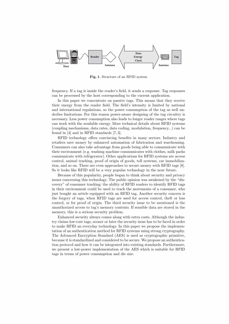
Each RFID system consists of a tag, which is attached to the object toidentify, and a reader which is able to retrieve data from the tag. The reader mayas well be able to write data to the tag’s memory. Additionally, to implementan application on data received from the tags, a host is used (see figure 1).Host commands are converted into reader requests and broadcasted via radio
⋆ This work origins from the Austrian Government funded project ART establishedunder the embedded system program FIT-IT.
Data Energy Clock
Tag Reader
Host Antenna Antenna
Fig. 1. Structure of an RFID system
frequency. If a tag is inside the reader’s field, it sends a response. Tag responsescan be processed by the host corresponding to the current application.
In this paper we concentrate on passive tags. This means that they receivetheir energy from the reader field. The field’s intensity is limited by nationaland international regulations, so the power consumption of the tag as well un-derlies limitations. For this reason power-aware designing of the tag circuitry isnecessary. Less power consumption also leads to longer reader ranges where tagscan work with the available energy. More technical details about RFID systems(coupling mechanisms, data rates, data coding, modulation, frequency...) can befound in [4] and in RFID standards [7, 3].
RFID technology offers convincing benefits in many sectors. Industry andretailers save money by enhanced automation of fabrication and warehousing.Consumers can also take advantage from goods being able to communicate withtheir environment (e.g. washing machine communicates with clothes, milk packscommunicate with refrigerator). Other applications for RFID systems are accesscontrol, animal tracking, proof of origin of goods, toll systems, car immobiliza-tion, and so on. There are even approaches to secure money with RFID tags [8].So it looks like RFID will be a very popular technology in the near future.
Because of this popularity, people began to think about security and privacyissues concerning this technology. The public opinion was awakened by the “dis-covery” of consumer tracking: the ability of RFID readers to identify RFID tagsin their environment could be used to track the movements of a consumer, whojust bought an article equipped with an RFID tag. Another security concern isthe forgery of tags, when RFID tags are used for access control, theft or losscontrol, or for proof of origin. The third security issue to be mentioned is theunauthorized access to tag’s memory contents. If sensible data are stored in thememory, this is a serious security problem.
Enhanced security always comes along with extra costs. Although the indus-try claims low-cost tags, sooner or later the security issue has to be faced in orderto make RFID an everyday technology. In this paper we propose the implemen-tation of an authentication method for RFID systems using strong cryptography.The Advanced Encryption Standard (AES) is used as cryptographic primitive,because it is standardized and considered to be secure. We propose an authentica-tion protocol and how it can be integrated into existing standards. Furthermore,we present a low-power implementation of the AES which is suitable for RFIDtags in terms of power consumption and die size.

2 Security Considerations for RFID Systems
RFID systems are susceptible to security attacks: as they work non-line-of-sightand contactless, an attacker can work remote and passive attacks will not be no-ticed. Some of the main concerns are (unwanted) consumer tracking, tag forgeryand the unauthorized access to the tag’s memory content. These security riskshave to be dealt with in order to gain a broad user acceptance.
2.1 Related Work
Some publications already deal with security aspects for RFID systems. Juels,Rivest, and Szydlo [9] propose so called “blocker tags” to protect consumers fromtracking. One tag simulates a broad range of ID numbers, so a reader cannotidentify it uniquely and tracking is circumvented. This was an approach to securelow-price tags which cost less than US$ 0.05.
Weis addresses the security and privacy issue of RFID systems in his masterthesis [17] and in another publication together with Sarma, Rivest, and Engels[18]. He also deals with low-cost tags for industrial applications. He suggests ahash-lock mechanism as access control and a randomized version of it to dealwith consumer tracking. He also presents some other concepts to enhance secu-rity in RFID tags. The assumptions made about the environment, for examplethat eavesdroppers cannot monitor signals from the tag, make the proposalssometimes not generally applicable.
Sarma, Weis, and Engels [15] also mention the problem of consumer trackingand recommend erasing the ID number of a tag at the point of sale as counter-measure. They also address the protection of tag contents and introduce theconcept of access control through mutual authentication of tag and reader.
Juels and Pappu make a proposal how to secure banknotes with RFID tags[8]. They want to reach various security goals, some of them are consumer pri-vacy, forgery resistance, and fraud detection. They propose a system which sat-isfies the requirements for all of the four main actors: the central bank, themerchants, the executive, and the consumer. The proposal in this publication isan RFID system using asymmetric cryptography combined with some methodswhich require physical access to the tag.
Finally, the “RFID Handbook” [4] deals with data security of RFID systemsby using authentication mechanisms. This is also the topic of our paper. Wepropose using strong cryptographic algorithms to perform authentication.
2.2 Authentication
Authentication means that an object proves its claimed identity to its commu-nication partner. This technique can solve all of the former mentioned securityproblems. Consumer tracking can be avoided, if tags only communicate theiridentity to authenticated readers. An unauthorized reader cannot get any in-formation about tags which are currently in its field. The authentication of thereader to the tags also solves the unauthorized-access problem. Only authorized
readers can read from or write to the tag’s memory. Authentication of a tagmeans that the tag proves its identity to the reader. A forged tag cannot con-vince the reader of its authenticity, so forgery of tags can be circumvented.
Menezes, Oorschot, and Vanstone [12] differentiate between three authen-tication methods: password systems (weak authentication), challenge-responseauthentication (strong authentication), and customized and zero-knowledge au-thentication. Password systems offer a weak level of security and zero-knowledgetechniques are often related to “strong” mathematical problems which are verycostly in calculation and implementation. So we aim for the second type, thechallenge-response techniques, which are broadly used.
There are asymmetric and symmetric challenge-response techniques. The dis-advantage of asymmetric authentication methods is that they are very time con-suming and costly to implement in hardware. So, they are not the first choicefor RFID systems. There were attempts to design resource-saving asymmetricauthentication algorithms. NTRU [5] has been proposed for RFID system im-plementations, but it was shown to have some security weaknesses [2, 11].
Symmetric methods work with one shared secret key. Authentication is doneby proofing the possession of this secret key. The problem when using symmetricauthentication methods is the key distribution and key management. Every up-date of the key has to be communicated to all participants. The compromisingof only one device holding the key affects the whole system. This problems andsome solutions were addressed in [12].
Symmetric authentication can be performed with encryption algorithms orcan be based on keyed hash functions. Various reasons made the AES algorithmour favorite to use for the proposed authentication protocol. This encryptionalgorithm was chosen 2001 as encryption standard [13] and is considered to behighly secure. Furthermore, it is well suited for hardware implementations.
Protocols for symmetric challenge-response techniques based on encryptionare defined in the ISO/IEC 9798-2 standard [6]. Unilateral authentication workas follows: there are two partners A and B. Both possess the same private keyK. B sends a random number rB to A. A encrypts the random number withthe shared key K and sends it back to B. B proofs the result and can verify theidentity (in other words the possession of K) of A.
A← B : rB (1)
A→ B : EK(rB) (2)
The mutual authentication protocol works similarly. B sends a random num-ber to A. A encrypts rB and a self-generated random number rA with the sharedkey K and sends it to B. B decrypts the message and can proof if rB is correctand gets rA. B changes the sequence of the random numbers encrypts it with K
and sends it to A. A proofs the result and verifies the identity of B.
A← B : rB (3)
A→ B : EK(rA, rB) (4)
A← B : EK(rB , rA) (5)

In order to minimize the power consumption and die size of the circuit, wedecided to design our circuit for AES encryption only. By using modified proto-cols one-way authentication as well as mutual authentication can be performed,even if no AES decryption is available. Mutual authentication protocols requirean additional random number generator, so they are more costly to implement.
2.3 Application Examples
Due to the key management problem, symmetric authentication methods aremore suitable for closed systems. In closed systems each component can be con-trolled by one central instance. All devices can get their keys and key updateseasily from the central control instance. In open systems, where the componentscan join the system unsolicited and no central control instance is available, keydistribution and management is more difficult.
In airport luggage tracking systems each controlled bag can be equipped withan RFID tag and can be tracked throughout the whole airport. All assigned tagnumbers are stored in a central server. In that way automated cargo and baggagetransportation systems as well as security applications are possible (access con-trol, checking if the holder of the bag is in the same plane as the luggage, etc.).Tag forgery and unauthorized access to the tag’s memory should be avoided.Luggage tracking should also only be possible for authorized readers.
During transportation, RFID systems can be used to track and route goodson their way from the factory to the retailer. Here, theft and loss of goods can berapidly detected, but the substitution with forged goods can only be avoided byusing tag authentication mechanisms. Authentication of the reader could be usedto prohibit unauthorized persons from spying the content of cargo. Tag memorycan be used to record environmental incidents (for example, the disruption of thecold chain when transporting food). In this case, memory access must be securedby using reader authentication to prevent unauthorized memory manipulation.
Another application are car immobilizers, where symmetric authenticationis already in use. In general, these implementations use proprietary encryptionalgorithms, which are optimized for the specific application. The security of thesealgorithms cannot be evaluated. Using AES would add some extra security. As afinal example, for proof of origin of goods authentication is essential. In the nextsection we propose a method to integrate an one-way authentication protocolinto existing RFID standards.
3 Security Protocol Design
In a security-enhanced RFID system, the level of security does not only rely uponthe strength of the used cryptographic algorithms. The used protocols play a de-cisive role whether an attacker can successfully break into a system or not. Evenif we use strong cryptographic algorithms, we need to ensure that the protocolis also secure. The protocol presented in this section allows the authenticationof an RFID tag to a reader using the Advanced Encryption Standard (AES) [13]

Reader
Tag1
Tag2
Send C 1 Send C 2 Send C 3 Rec R 1
Tag3
Rec R 2
Rec R 3
Resp R 1
Resp R 2
Resp R 3
...
R 1 = E K (C 1 )
R 2 = E K (C 2 )
R 3 = E K (C 3 )
0 10 20 30 40 50 60 t
[ms]
Fig. 2. Interleaved challenge-response protocol in RFID systems.
as the cryptographic primitive. In RFID systems, the limited computing powerand low-power constraints of the tags require special considerations concerningthe used protocols. In addition to the available bandwidth for data transmis-sion, attention should be paid to the compatibility to existing standards like theISO/IEC 18000 [7] or the Electronic Product Code (EPC) [3].
The protocol is based on the unilateral authentication mechanism usingrandom numbers presented in section 2. Integrating the presented challenge-response authentication protocol into the ISO/IEC 18000 [7] standard requiressome additional considerations. In addition to the mandatory commands, whichall tags must implement, custom commands can be specified. The two commands,integrated for authentication, are sending a challenge to the tag and requestingthe encrypted value. These commands extend the existing standard althoughthe basic functionality remains unchanged. Due to the low-power restrictions,the internal clock frequency of the RFID tag must be divided from 13.56 MHzto 100 kHz. The applied standard demands that a response must follow 320 µs
after a request. Otherwise, the tag has to stay quiet. This available time of 32clock cycles at a frequency of 100 kHz is not enough for encrypting a challengeusing the AES algorithm.
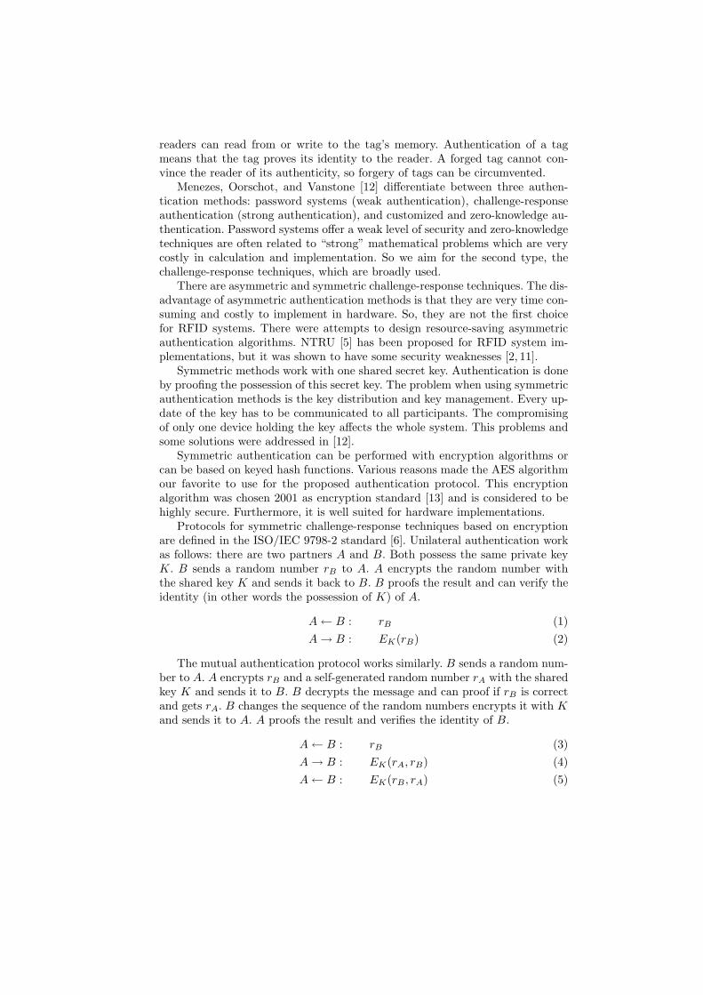
The solution to this problem is to modify the protocol as shown in figure2. The challenges and the responses to the tags are interleaved to each other.Normally, there are a lot of RFID tags to be authenticated in the environment ofa reader. After retrieving all unique IDs of the tags using the inventory requestand the anti-collision sequence, the reader sends a challenge C1 to Tag1. This tagimmediately starts the encryption of the challenge without sending any response.In the meanwhile, the reader sends further challenges to the tags Tag2 andTag3. They also start encrypting their challenges after reception. After finishingthe encryption of EK(C1), Tag1 waits for the request to send the encryptedvalue R1 back to the reader. When the reader has sent the three challenges,it sends a request for receiving the response from Tag1. The received valueR1 is verified by encrypting the challenge C1 and comparing the result with thereceived value. The two other unanswered challenges are received using the same

Digital Control
Analog Interface
EEPROM
AES VDD
Data
CLK
Fig. 3. Architecture of an RFID tag.
method. Then the reader starts from the beginning authenticating all other tagsin the environment. This protocol was evaluated using high level models of theRFID communication channel and is a proof of concept for future research onauthentication protocols in RFID systems.
This interleaving challenge-response protocol has the advantage that eachtag has at least 18 ms (1800 clock cycles at a clock frequency of 100 kHz) timefor encryption. A maximum of 50 tags can be authenticated per second. If thereare only few tags in the range of a reader, the reader can decide to make breaksof at least 18 ms instead of sending interleaved requests.
4 RFID Tag Architecture
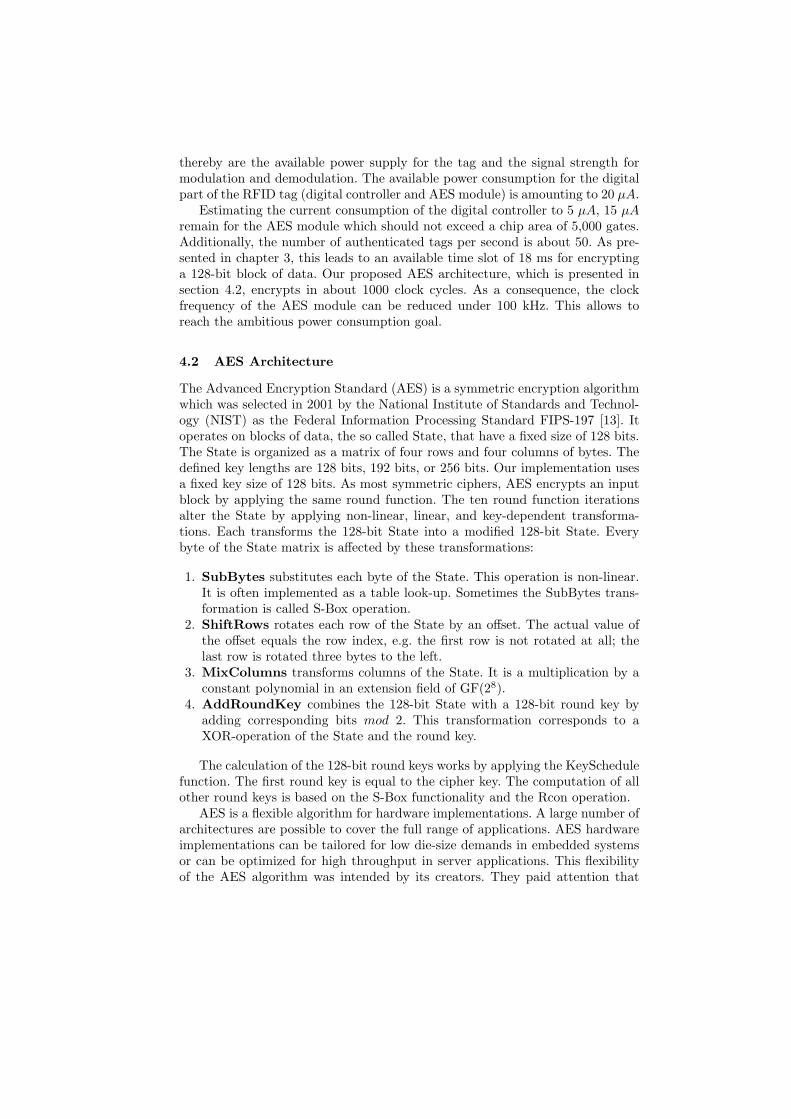
The architecture of a security-enhanced RFID tag is sketched in figure 3. Itconsists of four parts: analog frontend, digital controller, EEPROM, and AESmodule. The analog frontend is responsible for the power supply of the tag whichis transmitted from the reader to the tag. Other tasks of the analog frontendare the modulation and demodulation of data and the clock recovery from thecarrier frequency. The digital control unit is a finite state machine that handlescommunication with the reader, implements the anti-collision mechanism, andexecutes the commands in the protocol. Furthermore, it allows read and writeaccess to the EEPROM and the AES module. The EEPROM stores tag-specificdata like the unique ID and the cryptographic key. These data must be retainedwhen the power supply is lost. The security-enhanced RFID tag calculates strongcryptographic authentication with an AES module which is designed for low-power requirements and low die-size restrictions. The requirements concerningpower consumption and chip area and a description of the AES module arepresented in the following sections.
4.1 Requirements for RFID Tag Design
In order to achieve a significant economic benefit from using RFID systems,tags will need to be priced under US$ 0.10 [15] for simple identification tagsand a little bit higher for security-enhanced tags. Additionally to the aspect oflow cost, the environmental conditions play a decisive role because contactlessidentification must work within a distance of a few meters. The limiting factors
thereby are the available power supply for the tag and the signal strength formodulation and demodulation. The available power consumption for the digitalpart of the RFID tag (digital controller and AES module) is amounting to 20 µA.
Estimating the current consumption of the digital controller to 5 µA, 15 µA
remain for the AES module which should not exceed a chip area of 5,000 gates.Additionally, the number of authenticated tags per second is about 50. As pre-sented in chapter 3, this leads to an available time slot of 18 ms for encryptinga 128-bit block of data. Our proposed AES architecture, which is presented insection 4.2, encrypts in about 1000 clock cycles. As a consequence, the clockfrequency of the AES module can be reduced under 100 kHz. This allows toreach the ambitious power consumption goal.
4.2 AES Architecture
The Advanced Encryption Standard (AES) is a symmetric encryption algorithmwhich was selected in 2001 by the National Institute of Standards and Technol-ogy (NIST) as the Federal Information Processing Standard FIPS-197 [13]. Itoperates on blocks of data, the so called State, that have a fixed size of 128 bits.The State is organized as a matrix of four rows and four columns of bytes. Thedefined key lengths are 128 bits, 192 bits, or 256 bits. Our implementation usesa fixed key size of 128 bits. As most symmetric ciphers, AES encrypts an inputblock by applying the same round function. The ten round function iterationsalter the State by applying non-linear, linear, and key-dependent transforma-tions. Each transforms the 128-bit State into a modified 128-bit State. Everybyte of the State matrix is affected by these transformations:
1. SubBytes substitutes each byte of the State. This operation is non-linear.It is often implemented as a table look-up. Sometimes the SubBytes trans-formation is called S-Box operation.
2. ShiftRows rotates each row of the State by an offset. The actual value ofthe offset equals the row index, e.g. the first row is not rotated at all; thelast row is rotated three bytes to the left.
3. MixColumns transforms columns of the State. It is a multiplication by aconstant polynomial in an extension field of GF(28).
4. AddRoundKey combines the 128-bit State with a 128-bit round key byadding corresponding bits mod 2. This transformation corresponds to aXOR-operation of the State and the round key.
The calculation of the 128-bit round keys works by applying the KeySchedulefunction. The first round key is equal to the cipher key. The computation of allother round keys is based on the S-Box functionality and the Rcon operation.
AES is a flexible algorithm for hardware implementations. A large number ofarchitectures are possible to cover the full range of applications. AES hardwareimplementations can be tailored for low die-size demands in embedded systemsor can be optimized for high throughput in server applications. This flexibilityof the AES algorithm was intended by its creators. They paid attention that

the algorithm can be implemented on systems with different bus sizes. Efficientimplementations are possible on 8-bit, 32-bit, 64-bit, and 128-bit platforms.
Although many AES hardware architectures have been proposed, none ofthe reported architectures meets the requirements of an AES module for RFIDtags regarding low die-size and low power-consumption requirements. Nearly allof these architectures have GBit throughput rates as optimization goal. Thisis contrarious to our needs where throughput is not of concern. Only a fewpublished AES architectures do not optimize throughput at any cost. To namesome: [14, 1] are FPGA implementations and [10, 16] are ASIC implementationsof AES which care about hardware efficiency. All these implementations do notunroll the AES rounds for sake of silicon size. The more S-Boxes are used, the lessclock cycles are needed for encryption. The encryption-only AES processor of I.Verbauwhede et al. [16] is a 128-bit architecture that utilizes 32 S-Boxes. It isable to calculate one AES round in a single clock cycle. The compact 32-bit AESarchitecture of S. Mangard et al. in [10] is confident with four S-Boxes and takeseight cycles for one round. The FGPA implementations of N. Pramstaller et al.[14] and P. Chodowiec et al. [1] are 32-bit architectures too. They also use fourS-Boxes. Four S-Boxes suit a 32-bit architecture as each S-Box substitutes 8 bits.The MixColumns operation and the ShiftRows operation are 32-bit operationstoo because they transform either four columns bytes or four row bytes of theAES State. The AddRoundKey operation (128-bit XOR) can also be split-upinto 32-bit operations.
Implementing the AES algorithm as a 32-bit architecture allows to quarterthe hardware resources compared to an 128-bit architecture [10, 1]. This comes atthe expense of quadrupling the time for an AES encryption. The lower amount ofhardware resources has a positive side effect on the power consumption: a quarterof hardware resources consumes only a quarter of power. This is an importantfeature for wireless devices where the average power consumption is an evenmore important quality aspect than the overall energy needed to encrypt oneblock. The overall energy consumption of a 32-bit architecture might be worsethan for 128-bit architectures. But RFID tags offer neither the silicon space noris the electromagnetic field strong enough to power an 128-bit datapath.
The power requirements for RFID tags are even too restrictive to allow theoperation of a 32-bit AES implementation. Therefore, we decided to implementthe AES algorithm as an 8-bit architecture instead of a 32-bit architecture.This novel approach for a hardware implementation of the AES algorithm ismotivated by two reasons. First, an 8-bit architecture allows to decrease thenumber of S-Boxes from four to one to save silicon resources. Second, 8-bitoperations consume significantly less power than 32-bit operations do. A penaltyof an 8-bit architecture is the increased number of clock cycles for encryption. InRFID authentication applications an encryption lasting for 1000 cycles does notdeteriorate the authentication throughput when several tags are authenticatedconcurrently (see section 3).
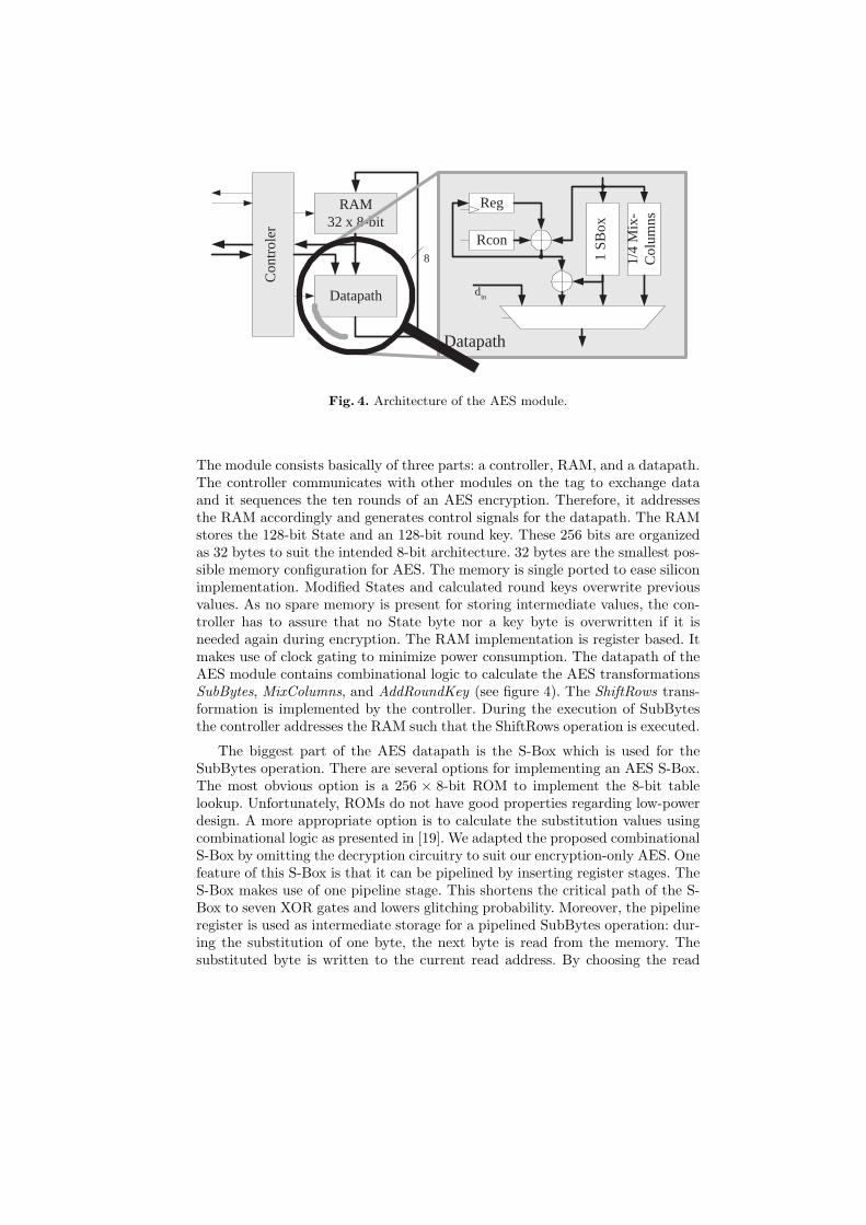
The architecture of the proposed 8-bit AES module is depicted in figure 4.It is presumably the smallest hardware implementation of the AES algorithm.
Con
trol
er
RAM 32 x 8-bit
Datapath
8
Datapath
1/4
Mix
- C
olum
ns
1 SB
ox
d in
Rcon
Reg
Fig. 4. Architecture of the AES module.
The module consists basically of three parts: a controller, RAM, and a datapath.The controller communicates with other modules on the tag to exchange dataand it sequences the ten rounds of an AES encryption. Therefore, it addressesthe RAM accordingly and generates control signals for the datapath. The RAMstores the 128-bit State and an 128-bit round key. These 256 bits are organizedas 32 bytes to suit the intended 8-bit architecture. 32 bytes are the smallest pos-sible memory configuration for AES. The memory is single ported to ease siliconimplementation. Modified States and calculated round keys overwrite previousvalues. As no spare memory is present for storing intermediate values, the con-troller has to assure that no State byte nor a key byte is overwritten if it isneeded again during encryption. The RAM implementation is register based. Itmakes use of clock gating to minimize power consumption. The datapath of theAES module contains combinational logic to calculate the AES transformationsSubBytes, MixColumns, and AddRoundKey (see figure 4). The ShiftRows trans-formation is implemented by the controller. During the execution of SubBytesthe controller addresses the RAM such that the ShiftRows operation is executed.
The biggest part of the AES datapath is the S-Box which is used for theSubBytes operation. There are several options for implementing an AES S-Box.The most obvious option is a 256 × 8-bit ROM to implement the 8-bit tablelookup. Unfortunately, ROMs do not have good properties regarding low-powerdesign. A more appropriate option is to calculate the substitution values usingcombinational logic as presented in [19]. We adapted the proposed combinationalS-Box by omitting the decryption circuitry to suit our encryption-only AES. Onefeature of this S-Box is that it can be pipelined by inserting register stages. TheS-Box makes use of one pipeline stage. This shortens the critical path of the S-Box to seven XOR gates and lowers glitching probability. Moreover, the pipelineregister is used as intermediate storage for a pipelined SubBytes operation: dur-ing the substitution of one byte, the next byte is read from the memory. Thesubstituted byte is written to the current read address. By choosing the read

addresses properly this procedure combines efficiently the SubBytes and theShiftRows operation. ShiftRows degrades to mere addressing.
Another innovative solution is the calculation of the MixColumns opera-tion. We achieved to build a submodule which calculates only one fourth of theMixColumns operation. By accessing the submodule four times a complete Mix-Columns operation for one column of the State is executed. The MixColumnsoperation for one column is shown in equation 6. The equation reveals that alloutput bytes qi of MixColumns are calculated by the same function—just theorder of the input column bytes ai differs.
q(x) = a(x) · c(x) = mod n(x) (6)
q0 = (a0 ⊗ {02})⊕ (a3 ⊗ {01})⊕ (a2 ⊗ {01})⊕ (a1 ⊗ {03})
q1 = (a1 ⊗ {02})⊕ (a0 ⊗ {01})⊕ (a3 ⊗ {01})⊕ (a2 ⊗ {03})
q2 = (a2 ⊗ {02})⊕ (a1 ⊗ {01})⊕ (a0 ⊗ {01})⊕ (a3 ⊗ {03})
q3 = (a3 ⊗ {02})⊕ (a2 ⊗ {01})⊕ (a1 ⊗ {01})⊕ (a0 ⊗ {03}).
We used this property to reduce the MixColumns circuitry to one fourth ofits original size. The resulting circuit can calculate one output byte in one clockcycle. The 1
4-MixColumns circuit contains, besides the combinational circuit to
calculate qi, three 8-bit registers to store three input column bytes ai. Theseregisters have to be filled before the first output qi can be calculated. The fourthinput ai is taken directly from the RAM. Consequent output values are calculatedby shifting the RAM output value to the registers and selecting the next valuefrom RAM. The processing of one column takes seven clock cycles. A completeMixColumns operation to transform the entire State takes 28 clock cycles. Thecritical path of the MixColumns circuit is even shorter than the S-Box.
Remaining components of the datapath are the submodule Rcon, some XORgates and an 8-bit register. Rcon is a simple circuit needed for key schedule. TheXOR gates are needed for round key generation and are used to combine theState with the round key during the AddRoundKey transformation. The 8-bitregister is needed during key schedule for storing intermediate results.
An encryption of a plaintext block works as follows. Before encryption isstarted the plaintext block has to be loaded into the RAM of the AES module.In the RFID tag application, the plaintext block is the 128-bit challenge whichwas received from the reader. The communication between the reader and tagis byte-oriented which fits nicely into the 8-bit architecture of the AES module:every received byte can be stored in the AES module. No intermediate memoryis necessary. The cryptographic key is obtained in a similar way from the tag’sEEPROM. Now the AES algorithm can be executed. It starts with a modificationof the State by an AddRoundKey operation using the unaltered cipher key.Ten AES rounds follow by applying the transformations SubBytes, ShiftRows,MixColumns, and AddRoundKey. Only the last round lacks the MixColumnsoperation. Roundkeys are calculated just in time. This is usually called on-the-fly key schedule. The round key is derived from its predecessor by using theS-Box, the Rcon, and the XOR functionality of the datapath.

Table 1. Components and their com-plexity of the AES module.
Module/ µA ClockComponent @100kHz GE cycles
S-Box 0.67 395 280
MixColumns 0.41 252 288
AddRoundKey 0.53 90 144
KeySchedule 0.92 161 304
RAM 4.64 2,337
Controller 0.98 360
Total 8.15 3,595 1,016
Table 2. Comparison based on energy con-sumption, gate count, and clock cycles.
AES-128 µA ClockEncryption @100kHz GE cycles
This work 8.15 3,628 992
Mangard [10] 47.24 10,799 64
Verbauwhede [16] 307 173K 10
5 Results
The implementation of the datapath of our AES-128 encryption design has acurrent consumption of 8.15 µA on a 0.35 µm CMOS process. It operates ata frequency of 100 kHz and needs 1,016 clock cycles for encryption of an 128-bit data block. The required hardware complexity is estimated to be 3,595 gateequivalents (GEs). All presented results come from simulations on transistorlevel. The complexity of each component is listed in table 1. Table 2 presentsa comparison of our approach with the 32-bit implementation of S. Mangardet al. [10] and the 128-bit encryption-only AES processor of I. Verbauwhede etal. [16]. It can be seen that only our solution achieves the high demands forintegrating cryptographic components into RFID tags. These requirements arethe low power consumption and low die-size while conforming the requirementsconcerning encryption speed.
6 Conclusions and Future Research
This paper presented a security-enhanced RFID system which allows the strongcryptographic authentication. With this security-enhanced RFID systems, wepave the way for new security-demanding applications and for the everyday usageof RFID technology. A symmetric challenge-response authentication protocolwas proposed which was integrated into the existing ISO/IEC 18000 standard.We showed an architecture for a low-power and low die-size implementation ofthe AES algorithm. The AES implementation has a chip area of 3,595 gates andhas a current consumption of 8.15 µA at a frequency of 100 kHz. The encryptionof 128 bits requires about 1000 clock cycles.
Future work will consist in the examination of advanced authentication pro-tocols for one-way and mutual authentication. Other authentication methods(e.g. asymmetric techniques) should be analyzed for the suitability for RFIDsystems and circuits can be found for this purpose. In this way, the applicationrange for RFID systems will be pushed further.

References
1. P. Chodowiec and K. Gaj. Very Compact FPGA Implementation of the AES Algo-rithm. In C. D. Walter, Cetin Kaya Koc, and C. Paar, editors, Cryptographic Hard-ware and Embedded Systems - CHES 2003, 5th International Workshop, Cologne,Germany, September 8-10, 2003, Proceedings, volume 2779 of Lecture Notes inComputer Science, pages 319–333. Springer, 2003.
2. W. Diffie and M. Hellman. Cryptanalysis of the NTRU Signature Scheme (NSS).In ASIACRYPT: International Conference on the Theory and Application of Cryp-tology, volume 2248 of Lecture Notes in Computer Science. Springer, June 2001.
3. EPCglobal. 13.56 MHz ISM Band Class 1 Radio Frequency (RF) IdentificationTag Interface Specification. http://www.epcglobalinc.org/, February 2003.
4. K. Finkenzeller. RFID-Handbook. Carl Hanser Verlag Munchen, 2nd edition, April2003.
5. J. Hoffstein, J. Pipher, and J. H. Silverman. NTRU: A Ring-Based Public KeyCryptosystem. In Algorithmic Number Theory, Third International Symposium,ANTS-III, Portland, Oregon, USA, June 21-25, 1998, Proceedings, volume 1423of Lecture Notes in Computer Science, pages 267–288. Springer, 1998.
6. International Organization for Standardization. ISO/IEC 9798-2: InformationTechnology - Security techniques — Entity Authentication Mechanisms Part 2:Entity authentication using symmetric techniques. ISO/IEC, 1993.
7. International Organization for Standardization. ISO/IEC 18000-3. InformationTechnology AIDC Techniques — RFID for Item Management, March 2003.
8. A. Juels and R. Pappu. Squealing Euros: Privacy protection in RFID-enabledbanknotes. In Financial Cryptography, 7th International Conference, FC 2003,Guadeloupe, French West Indies, January 27-30, 2003, Revised Papers, volume2742 of Lecture Notes in Computer Science, pages 103–121. Springer, 2003.
9. A. Juels, R. L. Rivest, and M. Szydlo. The Blocker Tag: Selective Blocking ofRFID Tags for Consumer Privacy. In Proceedings of the 10th ACM Conference onComputer and Communication Security, pages 103–111. ACM Press, 2003.
10. S. Mangard, M. Aigner, and S. Dominikus. A Highly Regular and Scalable AESHardware Architecture. IEEE Transactions on Computers, 52(4):483–491, April2003.
11. A. May. Cryptanalysis of NTRU. preprint, (unpublished), February 1999.12. A. J. Menezes, P. C. van Oorschot, and S. A. Vanstone. Hand-
book of Applied Cryptography. CRC Press, 1997. Available online athttp://www.cacr.math.uwaterloo.ca/hac/.
13. National Institute of Standards and Technology (NIST). FIPS-197:Advanced Encryption Standard, November 2001. Available online athttp://www.itl.nist.gov/fipspubs/.
14. N. Pramstaller and J. Wolkerstorfer. An Efficient AES Implementation for Recon-figurable Devices. In Austrochip 2003, Linz, Austria, October 1st, 2003, Proceed-ings, pages 5–8, 2003.
15. S. E. Sarma, S. A. Weis, and D. W. Engels. RFID Systems and Security andPrivacy Implications. In Cryptographic Hardware and Embedded Systems - CHES2002, 4th International Workshop, Redwood Shores, CA, USA, August 13-15, 2002,Revised Papers, volume 2523 of Lecture Notes in Computer Science, pages 454–470.Springer, 2002.
16. I. Verbauwhede, P. Schaumont, and H. Kuo. Design and Performance Testingof a 2.29 Gb/s Rijndael Processor. IEEE Journal of Solid-State Circuits, pages569–572, March 2003.
17. S. A. Weis. Security and Privacy in Radio-Frequency Identification Devices. Mas-ter’s thesis, Massachusetts Institute of Technology, Cambridge, MA 02139, May2003.
18. S. A. Weis, S. E. Sarma, R. L. Rivest, and D. W. Engels. Security and PrivacyAspects of Low-Cost Radio Frequency Identification Systems. In Security in Per-vasive Computing, 1st Annual Conference on Security in Pervasive Computing,Boppard, Germany, March 12-14, 2003, Revised Papers, volume 2802 of LectureNotes in Computer Science, pages 201–212. Springer, 2004.
19. J. Wolkerstorfer, E. Oswald, and M. Lamberger. An ASIC implementation of theAES SBoxes. In Topics in Cryptology - CT-RSA 2002, The Cryptographer’s Trackat the RSA Conference, 2002, San Jose, CA, USA, February 18-22, 2002, volume2271 of Lecture Notes in Computer Science, pages 67–78. Springer, 2002.