strom water harvesting
TRANSCRIPT

R.M.S POLYTECHNIC
WAGHODIA
MAJOR PROJECT
ON
RAIN WATER HARVESTING
GUIDED BY
VAISHALI SHAH
DUSHYANT SIKLIGAR
PREPARED BY:
NAME OF STUDENT ENROLLMENT NO. SHAH CHINTAN 096420306009
NAGARBANDHARA SAGAR
096420306015
MEHTA HARSHVARDHAN
096420306019
R.M.S POLYTECHNIC
WAGHODIA
TERM WORK REPORT
SUBJECT : PROJECT - 2
SUBJECT CODE : 2360605
DISCIPLINE : CIVIL ENGINEERING
ENROLMENT NUMBER : 096420306009
NAME OF STUDENT : SHAH CHINTAN D.
DIVISION/BATCH : CIVIL C6
SUBMISSION
SUBMITTED – 5 SEM :
SUBMITTED – 6 SEM :

R.M.S POLYTECHNIC
WAGHODIA
TERM WORK REPORT
SUBJECT : PROJECT - 2
SUBJECT CODE : 2360605
DISCIPLINE : CIVIL ENGINEERING
ENROLMENT NUMBER : 096420306015
NAME OF STUDENT : NAGARBANDHRA SAGAR M.
DIVISION/BATCH : CIVIL C6
SUBMISSION
SUBMITTED – 5 SEM :
SUBMITTED – 6 SEM :

R.M.S POLYTECHNIC
WAGHODIA
TERM WORK REPORT
SUBJECT : PROJECT - 2
SUBJECT CODE : 2360605
DISCIPLINE : CIVIL ENGINEERING
ENROLMENT NUMBER : 096420306019
NAME OF STUDENT : MEHTA HARSHVARDHAN S.
DIVISION/BATCH : CIVIL C6
SUBMISSION
SUBMITTED – 5 SEM :
SUBMITTED – 6 SEM :

CERTIFICATE
THIS IS TO CERTIFY THAT
SHAH CHINTAN D, NAGARBANDHARA SAGAR M,
MEHTA HARSHVARDHAN S.
HAS SATISFACTORILY COMPLETED HIS TERM WORK
IN THE SUBJECT
PROJECT-2 (2360605)
WITHIN THE PRESCRIBED TIME LIMIT AND
PRESCRIBED BOUNDRY.
DATE STUDENT
DATE INSTITUTE GUIDE
DATE HEAD OF DEPT.
DATE PRINCIPAL
CERTIFICATE
THIS IS TO CERTIFY THAT
SHAH CHINTAN D.
HAS SATISFACTORILY COMPLETED HIS TERM WORK
IN THE SUBJECT
PROJECT-2 (2360605)
WITHIN THE PRESCRIBED TIME LIMIT AND
PRESCRIBED BOUNDRY.
DATE STUDENT
DATE INSTITUTE GUIDE
DATE HEAD OF DEPT.
DATE PRINCIPAL

CERTIFICATE
THIS IS TO CERTIFY THAT
NAGARBANDHARA SAGAR M.
HAS SATISFACTORILY COMPLETED HIS TERM WORK
IN THE SUBJECT
PROJECT-2 (2360605)
WITHIN THE PRESCRIBED TIME LIMIT AND
PRESCRIBED BOUNDRY.
DATE STUDENT
DATE INSTITUTE GUIDE
DATE HEAD OF DEPT.
DATE PRINCIPAL

CERTIFICATE
THIS IS TO CERTIFY THAT
MEHTA HARSHVARDHAN S.
HAS SATISFACTORILY COMPLETED HIS TERM WORK
IN THE SUBJECT
PROJECT-2 (2360605)
WITHIN THE PRESCRIBED TIME LIMIT AND
PRESCRIBED BOUNDRY.
DATE STUDENT
DATE INSTITUTE GUIDE
DATE HEAD OF DEPT.
DATE PRINCIPAL

ACKNOWLEDGEMENT
We are feeling pleasure introducing or project on “STROM
WATER HARVESTING” results of our new radical ideas to
significantly wind up studies during in course “DIPLOMA IN
CIVIL ENGINEERING” in “R.M.S POLYTECHNIC,
WAGHODIA”. Suggestions to improve quality of products are
always welcome. Many hands have given their active support and
contributed for design, development and production of contribution
individually. Mainly the contribution of co-ordination of work and
staff of “R.M.S POLYTECHNIC, WAGHODIA” are highly
acknowledged. We are highly obliged to following professors for
their kind support and timely guidance given us to reach our
destination with perfection.
GUIDED BY
VAISHALI SHAH
DUSHYANT SIKLIGAR
OUR GROUP PARTICIPANTS ARE
NAME OF STUDENT ENROLLMENT NO. SHAH CHINTAN. 096420306009
NAGARBANDHARA
SAGAR 096420306015
MEHTA
HARSHVARDHAN 096420306019

INDEX
1. INTODUCTION
2. STORM WATER DRAINAGE DESIGN
3. THE IMPACT OF URBEN STORM WATER RUNOFF
4. PRINCIPLE OF RUNOFF
5. DESIGN CRITERIA
6. SUSTAINABILITY
7. LEVEL OF SERVICE
8. OTHER DESIGN ISSUES
9. SUMMERY OF DESIGN CRITERIA
10. HYDROLIC DESIGN OF DRINAGE COMPONANTS
11. GENRAL ISSUES RELATED DRINAGE DESIGN
12. STORM WATER PIPE DESIGN
13. ATTENUATION STORAGE DESIGN
14. ASSESSMENT OF GRRENFIELD SITE RATE OF
RUNOFF
15. ASSESSNMENT OF DEVLOPMENT RUNOFF RATE
16. LONG TERM STORAGE DESIGN
17. ASSESSMENT OF DEVLOPMENT RUNOFF
VOLUMES
18. ASSESSMENT OF GREENFIELD RUNOFF VOLUMES
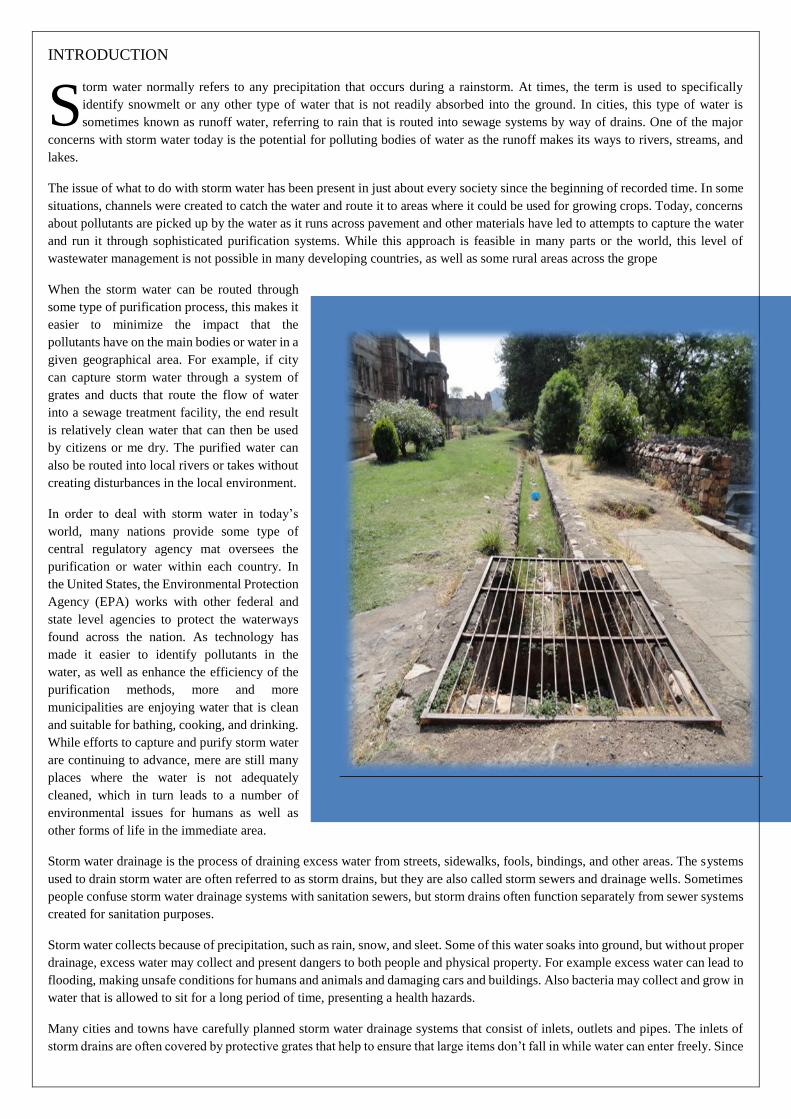
INTRODUCTION
torm water normally refers to any precipitation that occurs during a rainstorm. At times, the term is used to specifically
identify snowmelt or any other type of water that is not readily absorbed into the ground. In cities, this type of water is
sometimes known as runoff water, referring to rain that is routed into sewage systems by way of drains. One of the major
concerns with storm water today is the potential for polluting bodies of water as the runoff makes its ways to rivers, streams, and
lakes.
The issue of what to do with storm water has been present in just about every society since the beginning of recorded time. In some
situations, channels were created to catch the water and route it to areas where it could be used for growing crops. Today, concerns
about pollutants are picked up by the water as it runs across pavement and other materials have led to attempts to capture the water
and run it through sophisticated purification systems. While this approach is feasible in many parts or the world, this level of
wastewater management is not possible in many developing countries, as well as some rural areas across the grope
When the storm water can be routed through
some type of purification process, this makes it
easier to minimize the impact that the
pollutants have on the main bodies or water in a
given geographical area. For example, if city
can capture storm water through a system of
grates and ducts that route the flow of water
into a sewage treatment facility, the end result
is relatively clean water that can then be used
by citizens or me dry. The purified water can
also be routed into local rivers or takes without
creating disturbances in the local environment.
In order to deal with storm water in today‟s
world, many nations provide some type of
central regulatory agency mat oversees the
purification or water within each country. In
the United States, the Environmental Protection
Agency (EPA) works with other federal and
state level agencies to protect the waterways
found across the nation. As technology has
made it easier to identify pollutants in the
water, as well as enhance the efficiency of the
purification methods, more and more
municipalities are enjoying water that is clean
and suitable for bathing, cooking, and drinking.
While efforts to capture and purify storm water
are continuing to advance, mere are still many
places where the water is not adequately
cleaned, which in turn leads to a number of
environmental issues for humans as well as
other forms of life in the immediate area.
Storm water drainage is the process of draining excess water from streets, sidewalks, fools, bindings, and other areas. The systems
used to drain storm water are often referred to as storm drains, but they are also called storm sewers and drainage wells. Sometimes
people confuse storm water drainage systems with sanitation sewers, but storm drains often function separately from sewer systems
created for sanitation purposes.
Storm water collects because of precipitation, such as rain, snow, and sleet. Some of this water soaks into ground, but without proper
drainage, excess water may collect and present dangers to both people and physical property. For example excess water can lead to
flooding, making unsafe conditions for humans and animals and damaging cars and buildings. Also bacteria may collect and grow in
water that is allowed to sit for a long period of time, presenting a health hazards.
Many cities and towns have carefully planned storm water drainage systems that consist of inlets, outlets and pipes. The inlets of
storm drains are often covered by protective grates that help to ensure that large items don‟t fall in while water can enter freely. Since
S

it‟s important for large amounts of water to flow into these drains the bars of the grates must be spaced some distance from each
others. This concessions means that some smaller objects to do fall into the drain.
Once the water enters to storm drain, it usually flows to a catch basin which catches small objects before the water continues its
journey into the sewer. Next, the piping comes into play. Storm drainage systems can have different types of pipes. Some many be
rectangular in shape while others are circular or oval. The material may differ as well with some systems using concrete or metal
while others use plastic additionally some drainage pipes have mechanisms in place for catching debris, such as pollutant traps.
The storm water drainage systems maintained by cities and towns usually drain to a single point and outlet tends to be rather large
and covered by another grate. Often, these systems drain into lakes, rivers, or reservoirs. In some cases, they may drain into a canal
or ocean instead.
Though, necessary storm water drainage can have a significant impact on the environment. Unfortunately, toxic substances, such as lawn fertilizers, cigarette butts, motor oil pesticides, and other chemicals are often washed into storm water drainage systems. These chemicals lead to polluted water that ends up in lakes, streams rivers, oceans, and other bodies of water, where it proves unhealthy for fish, plants, and other water life, even killing them. In turn, humans and animals may be sickened by eating the contaminated fish.
STORM WATER MANAGEMENT
Storm water management is a fundamental consideration in the planning and design of urban development. By considering storm
water management at the initial design phase it is possible to ensure viable storm water management solutions that are
compatible with other design objectives for the site.
SITE ANALYSIS
The site‟s topography will have a significant impact on the layout design. This is because storm water drainage
systems almost always rely on gravity. The layout of the development m u s t b e c o n f i g u r e d s o a s t o a l l o w
e x c e s s s t o r m w a t e r t o b e g r a v i t y - d r a i n e d t o a d r a i n a g e system. Topography will also affect runoff onto the site
from surrounding properties. Existing o v e r l a n d f l o w p a t h s s h o u l d b e i d e n t i f i e d a n d r e t a i n e d . W h e r e
m o d i f i c a t i o n s t o t h e s e a r e unavoidable, they should be designed so as to maintain existing hydrological
conditions. Drainage easements, natural watercourses and flood prone land should also be identified and c o n s i d e r e d i n t h e
d e s i g n p r o c e s s . I t n e e d s t o b e b o r n e i n m i n d t h a t d r a i n a g e e a s e m e n t s containing underground pipes can
operate as overland flow paths during intense rainfall events. Buildings must be kept clear of drainage easements
to ensure public safety and to a l l o w m a i n t e n a n c e a c c e s s . C o n s i d e r a t i o n a l s o n e e d s t o b e g i v e n t o l o c a l
s o i l c o n d i t i o n s . Relevant factors include absorption capacity, erosion potential, soil salinity and the possibility of soil
contamination from past activities
ADJOINING PROPERTIES
One of the basic principles of storm water management is to avoid adverse storm water impacts on other properties. Careful
consideration must be given to controlling surface runoff and subsoil drainage to adjoining properties. The
redirection and concentration of storm water flows onto neighboring properties may constitute a „nuisance‟ at common law,
giving affected owners a legal right of redress.
PUBLIC SAFETY
Storm water runoff from rare and intense storm events can pose serious risks to life and property. It is essential that the design of
overland flow paths, on-site detention storages and other storm water management measures meet relevant safety criteria for
pedestrians, vehicles and property damage. Fencing and landscaping should be designed so as to minimize the potential for overland
flow paths to be obstructed during rare and intense storm events.

STORM WATER DRAINAGE DESIGN
One of the most important factors in designing sustainable stormwater drainage systems is the physical storage
volume that needs to be provided to achieve flood control and minimise the pollution impact of urban stormwater
runoff.
This section on stormwater drainage begins by examining the performance of current drainage systems and the conditions that lead to both flooding and poor water quality. Further information on the management of inflow and
infiltration can be found in the Regional Drainage Policy on Inflow, Infiltration and Exfiltration.
Design and assessment criteria for sewers, rivers and SuDS measures are proposed together with design principles and
procedures for estimating volumes of individual SuDS facilities. Appendix E provides an illustration of the approach
for assessing stormwater storage requirements.
It is important to realise that all drainage systems are designed to a set of criteria that are subject to economic, social and
environmental constraints. It is not feasible to design for all circumstances and there will always be instances when
extreme events will exceed the design criteria. The design process therefore should be one of risk management,
whereby the consequences of larger events than the design event are assessed for their cost and environmental impacts.
The Impact of Urban Storm water Runoff
Rainfall runoff in an urban environment effectively takes place instantly for areas served by
traditional drainage systems and nearly all the rain that falls on impermeable surfaces runs off. The
rate of runoff and the volume of runoff are both important components in analysing the performance
of a network. For storms above a certain magnitude the performance of the network downstream
may be exceeded. Rainfall-related flooding of the drainage network, simply defined, is the
concentration of storm water to a point from which it cannot escape quickly enough to avoid ponding
or passing on as overland flow.
In addition to the hydraulic behavior of traditional drainage systems, their water quality management
characteristics are poor and this problem is now recognized as a major issue in terms of polluting receiving waters. The quality of receiving waters and the types of main pollutants are covered in detail in the Regional Policy for Environmental Management.
Open Channel Watercourses
While open channel watercourses, such as rivers and streams, normally have a greater hydraulic
capacity than piped systems, the consequences of flooding are usually greater due to the scale of
the event. This concern usually results in more conservative design criteria being used. The
consequences of flooding from a culverted watercourse are usually far more dramatic than with river
flooding. This is because the capacity of the river greatly increases as water levels rise, while the
capacity of a culvert by comparison, once surcharged, only marginally increases with the increase in
hydraulic head.
Culverting Rivers also causes significant ecological loss, as well as producing negative aesthetic impact and other
negative environmental effects. The water quality in open channel watercourses can be directly related to the
catchment land use, either urban or rural. The base flows in watercourses in urban areas are reduced, peak flows
during rainfall are higher and generally all measures of water quality show deterioration. This varies with land use type
(residential, industrial and commercial areas), and depends on storm water management techniques used. Spillages of
toxic material in industrial estates can be particularly destructive.

Principles of Storm water Design
The three principles behind the selection of design criteria are:
• Sustainability;
• Level of service;
• Cost-effectiveness.
Each of these three principles is expanded upon below. The drainage engineer should have a number of questions that are addressed by the proposed design. A non-exhaustive list includes:
♦ What are the normal operating and maintenance requirements of the design?
♦ What are the risks of failure of the proposed design and the consequences in terms of impact?
♦ What are the implications of failure for the rehabilitation of the system that will be needed?
♦ How effective will the system be in treating the storm water?
♦ What are the social / aesthetic benefits of the proposed design?
♦ What are the environmental benefits / protection of the proposed design?
If consideration is given to all these questions it will generally ensure that a sustainable drainage system is designed.
Sustainability
Sustainability can be defined in a number of ways, but in terms of drainage it can be interpreted as:
♦ Drainage systems should utilize natural resources which can be reused and are energy efficient in terms of constituent products and construction process
♦ Drainage systems should aim to replicate the natural characteristics of rainfall runoff for any site;
♦ The environmental impact of man should be minimized.
The concept of sustainability is now well accepted. This is resulting in a move away from traditional
drainage methods, and the recommended use of SuDS systems to provide hydraulic, water quality
and environmental benefits. In addition more attention is now being paid to the consumption of
natural resources and the ability to recycle these materials. The issue of climate change is now of
major importance and this draws attention to the energy aspects of construction. This includes not
only the energy requirements to build the drainage system, but also the energy requirements for its
maintenance and the energy needed to manufacture the components used in the system.
The design of the drainage system should try and replicate, in a general way, the same rainfall runoff characteristics for
the pre-development condition of the site. The runoff is much slower; less polluted and has virtually no runoff from
ordinary rainfall events. The use of SuDS, particularly components which encourage infiltration, will enable this
principle to be achieved.
The design of drainage systems needs to minimize water pollution and maximize environmental
benefits. SuDS units are designed to address storm water quality as well as providing hydraulic
conveyance. Consideration should also be given to what might happen if the drainage system “fails”
as well as its performance during normal operation. Due to the nature of SuDS units, the
consequences of failure tend to be less of a problem than failure of traditional drainage systems.

This is because failures of SuDS units tend to be incremental and not catastrophic as in the case of a pipe blockage or
collapse.
Level of Service
♦ Flood protection should be provided to a minimum level of service;
♦ No negative aesthetic effects;
♦ Social benefits;
♦ Safety.
The principal objective of drainage is to provide protection from flooding due to rainfall on an area. The level of service
provided is a function of society‟s expectations as well as the cost-benefit of the system based on the damage
consequences due to flooding. Current design criteria normally require that no flooding occurs up to the 30 year
return period, and properties are protected against flooding for the 100 year return period. The level of service for
existing systems is usually a lower standard, with 5 years being considered as a minimum requirement.
Although aesthetics are rarely considered as an issue of level of service provision, considerable expenditure in the
UK has been incurred in addressing aesthetic pollution from CSOs. As SuDS systems become more common, it is
important to ensure that these are aesthetically acceptable as well as acting as efficient drainage systems.
Certain SuDS provide the opportunity for dual land use. Attenuation structures such as ponds have to have the ability to
deal with events up to a 100 year return period. This requires large areas adjacent to these structures which are
normally dry and can be used for other purposes.
Safety is not really a primary level of service issue, but it is clearly an essential aspiration in providing an appropriate design of any system.
Cost-effectiveness
♦ Principles of whole life costing (WLC) should be applied.
Drainage design should aim to provide the most cost-effective solution, particularly in terms of
maintenance requirements. This requires consideration of whole-life costing of alternative options. Evaluation of the most appropriate system should include hydraulic, water quality and environmental benefits.
There is a limited, but growing data set of experience of the capital and operational costs of SuDS. In general, the cost of
SuDS systems are believed to be comparable to traditional drainage systems. Long-term performance of SuDS units is still being investigated, particularly with regard to the extent of the maintenance needed.
“Failure” mechanisms (flooding and pollution) are more robust for SuDS than traditional systems. It should be recognized that any drainage system can fail, whether it is a traditional system or SuDS.
Attention to design detail is important to ensure easy and effective maintenance of all drainage systems.
Design Criteria
Drainage design criteria needs to consider the above principles in order to produce the most appropriate system
for any location. Individual criterion can be developed to meet the various requirements of sustainability and levels
of service. of whole life costing does not result in specific criteria for design. Appropriate whole life costing requires
appropriate weighting of maintenance against capital costs by applying a Net Present Value method. Sensitivity
analysis should theoretically be carried out on various possible solutions to arrive at the most cost beneficial scheme
rather than rigidly sticking to a specific design standard

Sustainability
Energy and Use of Natural Resources
There are no design criteria that address the selection of appropriate drainage products and achieve the best design which
meets energy and natural resource objectives. However certain features of drainage systems such as the use of
pumping stations and large underground structures require considerable energy consumption in their construction
and operation. There is less information available with regards to making the most sustainable choice when deciding
between the use of one product over another. This is a complex area requiring a balance between costs, structural
properties of drainage units, site specific aspects, maintenance and, in the long-term, the dismantling and
disposal of the system.
Although there are no design criteria specifically addressing the minimization of energy consumption and the use of
natural resources, it is important for engineers to be aware that this is an issue which will become more important in the
future.
Environmental Impact
Environmental impact of urban storm water run-off is characterized by the high levels of sediment and other
pollutants, both particulate and dissolved, together with the volume and rate of flow of the run-off causing flooding and
erosion in the receiving water. Design criteria can be developed to address these various effects, but these are more
easily considered by breaking down the various environmental impacts into their individual components and by
comparing with the natural rainfall run-off processes which take place in the greenfield environment.
River Water Quality Protection
Run-off from natural green field areas (which are not farmed) contributes a nominal amount of
pollutant and sediment in run-off to rivers. For most rainfall events, rainfall depths and intensities are
relatively low and direct run-off to rivers does not take place with rainfall percolating into the ground.
This water eventually supports the base flow in the river days and weeks after the event has taken
place.
By contrast urban run-off, when drained by pipe systems, results in run-off from virtually every
rainfall event with high levels of pollution, particularly in the first part of the run-off, with little of the rainfall actually percolating into the ground. This results in virtually no support for the base flows in rivers.
Table summarizes the differences in urban and green field run-off processes and provides an indication of the design
criteria that need to be developed to enable urban run-off to more closely replicate the green field condition in
protecting river water quality. response
No direct runoff Direct runoff
Baseflow support Limited infiltration
No pollutants Highly polluted
The Contrast Between Urban and Greenfield Storm water Response for
Rainfall Events

Appropriate design criteria to address these differences are therefore:
♦ No run-off to pass directly to the river for rainfall depths of 5mm and up to 10mm if possible (interception);
♦ Use of infiltration drainage techniques;
♦ Use of storm water treatment techniques.
In practice, there are a number of practical constraints in applying these criteria. 10mm of rainfall
run-off from an urban area, especially with a high-density development, provides a considerable
volume of runoff. Infiltration may be a problem for several reasons; the first being that the soil may
be fairly impervious (clay), secondly groundwater levels may be high at certain times in the year and
thirdly wash off from certain surfaces, particularly roads, often contains high levels of polluted
sediment and, depending upon the maintenance regime, will usually result in blockage of infiltration
units over a period of time.
The fact that it might be difficult to comply with these design criteria in all circumstances does not mean that these
criteria are not valid. They should be applied wherever a reliable solution is possible. Where it is not possible to
store and dispose of 10 mm of rainfall, it might be possible to intercept runoff from 5 mm, which will still provide
considerable benefits. It should be noted that the issue of river pollution is particularly a problem in the summer when river
flows are low and dilution is minimal. However this is the period in which infiltration units are most likely to be effective as
the soil moisture deficit and evaporation rate is high.
Achieving zero runoff from the first 5mm or 10mm of rainfall is often not practicable, and therefore
emphasis is also needed on achieving some treatment of the storm water run-off. This ensures that any runoff discharged to the river is of significantly better quality than direct runoff from a pipe network.
The various advantages of the different SuDS units are described in some detail in chapter 4 of this document and also, more fully, in the Environmental Management policy document.
SuDS units that treat storm water include filter trenches, swales, wetlands, retention ponds and detention basins. One
of the most commonly used SuDS units is the retention pond. The design of the wet pond in terms of depth shape and
volume is covered in SuDS design manuals and also in the Environmental Management policy document. In terms of
design criteria to provide treatment, the concept of the “treatment volume” (Vt) has been defined for the permanent
pool volume of a retention pond. In the SuDS design manuals CIRIA C521 and C522 it is recommended that up to 4
times Vt is required to provide good treatment of the storm water volume.
The formula for Vt is:
Vt (m3/ha) = 9 x D (SOIL/2 + (1 - SOIL/2) x I)
Where:
I = fraction of the area which is impervious (30% impermeable area = 0.3) D = M5-60
rainfall depth (5 Year Return, 60 minute duration)
SOIL = Soil Classification (Flood Studies or the Wallingford Procedure WRAP map)
Vt is thus a function of local hydrological characteristics, soil type and the level of impermeability of
the catchment. The presumption is that the treatment volume (permanent pool) is sized to capture runoff from 90% of
storms that occur each year. The value for the Dublin region would be an
equivalent rainfall depth of around 20mm. Thus 4 times Vt would imply a storage volume of 80mm.
This is a very large volume of water and recent research suggests that the advantages of large
volumes of storage, particularly deep ponds, have limited benefits. It is becoming clear tha t long residence times can
result in the production of high levels of ammonia, due to anaerobic conditions in the sediments, which is very
poisonous to river crustaceans and fish.
Shallow ponds, although providing less opportunity for these conditions, have a number of limitations. These are:
♦ For any given volume, the shallower the pond the larger is the area needed;
♦ Plants will grow in depths of up to around 1m. This depth of open water cannot be guaranteed
for shallow ponds. This implies increased maintenance and also reduced aesthetic value of the pond.
It is therefore recommended that a figure of 15 mm of rainfall is used for the Dublin region to
determine the permanent pool volume, until research provides clear evidence as to what constitutes
best practice.
It should be noted that the Standard Percentage Runoff (SPR) indices for SOIL are different in the Flood Studies Report
(FSR) from the values in the Winter Rainfall Acceptance Potential (WRAP) map (from the Wallingford Procedure). This formula is generally applied using the WRAP values, but the difference is not worth debating.
Flows from large storms should be diverted around treatment facilities, with only runoff from ordinary events being treated. However as retention ponds are used to provide both treatment and also
hydraulic attenuation for extreme events, careful design is needed to prevent resuspension of sediments.
The design of pond water levels should take account of winter levels of groundwater. Lining a pond
(if needed to protect the a sensitive groundwater area from pollution) where ground water levels are
high in winter, should ensure that the design pond water level is higher than the groundwater or else
the pond liner will “float” up. If the pond is not to be lined, the groundwater level in summer needs to
be known to determine the likely minimum water level in dry summer periods. The range of the pond
water level in the seasons should be taken into account in its design, particularly its impact on barrier
planting vegetation. The fact that the water level may drop below the outlet control is not necessarily
a problem as no direct runoff to the watercourse reflects the normal green field response in dry
summer periods.
Although water quality and hydraulic design features are the principle focus when designing the drainage system,
it is important to maximize the environmental benefits of any design. Thus appropriate use of vegetation borders to
ponds using native plants which support local fauna is to be considered whenever designing a system. The gradient of the
ground at the edge of the pond should be designed to be fairly flat even though this may not be the most efficient
hydraulic solution and require some additional land.
Guidance on best practice design of retention ponds is available from SuDS design manuals. It is inappropriate to use
environmental criteria as primary design criteria. However environmental benefits need to be considered when
developing the design proposals.

River Regime Protection
Rural runoff to rivers, when it occurs, is slow. To try and replicate this, urban runoff must be heavily constrained.
Unrestrained runoff causes high velocities and erosion, affecting the morphology of the channel and the flora and fauna in
the river.
Relevant design criterion to address this issue is to:
♦ Restrain the rate of discharge to the receiving water to that of green field runoff for the site.
A range of formulae exist for predicting green field runoff. The simplest and the one considered most appropriate for
applying to this criterion was developed by the Institute of Hydrology in their report 124 “Flood estimation for small
catchments”, 1994.
The work was based on 71 small rural catchments. A regression equation was produced to calculate QBARrural the mean annual flood.
QBARrural = 0.00108AREA0.89
SAAR1.17
SOIL2.17
where:
QBARrural is the mean annual flood flow from a rural catchment in m3/s. AREA is the area
of the catchment in km2.
SAAR is the standard average annual rainfall for the period 1941 to 1970 in mm.
SOIL is the soil index, which is a composite index determined from soil survey maps that accompany the
Flood Studies Report.
QBAR can be factored using the Flood Studies Report regional growth curve for Ireland to produce
peak flood flows for a number of return periods. Information on growth curves for UK and Ireland is
available in Flood Studies Supplementary Report (FSSR) 14, 1987 produced by the Institute of
Hydrology.
There is some indication that the Irish growth curve is not applicable for some Dublin rivers. Preliminary work
carried out on the Carrick mines, Shanganagh and Tolka Rivers has resulted in an alternative growth curve being
proposed. The FSSR 14 growth curves together with the proposed regional curve for Dublin are shown in appendix C.
These will be updated in due course when more research is made into this issue.
The formula for determining the peak green field runoff rate should not be applied to areas less than
50 hectares. As many developments are smaller than this size this constraint is avoided by calculating QBAR for
50 hectares and linearly interpolating flow rates for smaller areas.
River Flooding Protection
River flooding has serious consequences for affected properties and therefore return periods of 100 years are usually
applied to determine the extent of floodplains and the risk to properties adjacent to watercourses. A return period of 200
years is normally recommended where flooding risk from the sea is possible. Flooding in rivers is exacerbated by urban
runoff, particularly in catchments with a high degree of urbanization. The floodplains provide a finite volume of storage,
so not only does the rate of runoff from urban areas need to be controlled, but also limiting the increase in volume of runoff
compared to green field conditions should also be considered.
Relevant design criteria to address river flooding are to:
♦ Restrain the excess volume of runoff from urban development‟s to that of green field runoff;
♦ Avoid development on the flood plain.

Excess Urban Runoff Volume
It is important to realize that many river flood events are the result of multiple rainfall events and therefore it is
unwise to try and design for the discharge to take place before or after the flood wave passing down the river. If all
catchments are developed on the basis of reflecting the rural behavior prior to development, both in terms of rate of runoff
and volume of runoff, it is likely that the river will be protected effectively.
This additional volume of storm water runoff is not a flooding issue in “normal” (frequent) rainfall events as long
as runoff rates from sites are constrained. However in extreme events, where flooding is likely to occur in the river,
it is important to limit this runoff volume. This can be achieved in the design of the drainage system by spilling from
the attenuation storage system to an area which will drain very slowly, preferably by infiltration. As this is a rare
event, by definition, this might be to a park or football field with appropriate land drainage provision at low points.
This storage might be termed “long term” storage for river flood protection.
The river floodplain should generally be used as open space for ecological reasons as well as being a river flood corridor
for extreme events. Planned development or even storage in the floodplain should generally be avoided. This is
partly due to the fact that the storage attenuation system is bypassed by being flooded, and also creates a problem in
terms of maintenance (depending on how frequently it is flooded). The likely consequence is that large volumes of
sediment will be deposited in the storage systems by the floodwater when this occurs.
To achieve the necessary volumes of long term stored runoff, the return period at which runoff will start to pass to such
an area will need to take place for events less than the 100 year event. However if flooding of the area occurs more often than say once in 10 years then the level of service for that public open space may be considered to be inadequate.
In some situations it might not be possible to achieve this approach. Also it requires detailed
technical analysis to enable this to be designed accurately. The alternative is to provide for this
volume in the form of infiltration which comes into effect for all storm events. This not only has the
advantage of simplicity of design, but also provides good environmental benefits in terms of base
flow support for rivers, and reduced runoff for small events (which replicates green field runoff). It
should be noted that infiltration in extreme wet periods will be less effective than at other times, so
infiltration storage should only be used where groundwater levels are known not to rise to the levels
of the proposed infiltration units. Although detailed calculations can be carried out to establish the
infiltration volumes needed by taking account of infiltration rates of the soil at the site, the soil
moisture state during particularly wet periods will tend to be saturated and antecedent conditions
may reduce the available storage volume. It is therefore suggested that the volume of storage
normally provided as infiltration to meet this criterion is equal to the calculated value of the additional
runoff volume. Detailed analysis, if carried out, can reduce this volume by taking into account the
infiltration that will take place during the critical duration event.
It is possible that “long term” storage cannot be provided at certain sites. In these situations it is recommended that
QBAR is used as the attenuation storage control requirement to ensure sufficient runoff is retained on site for extreme
events. This will tend to be a less economic solution, but is the only way to ensure that urban runoff does not exacerbate
flooding in a river. Where QBAR is a value which is less than 2 l/s/ha it is recommended that this figure is used to
prevent excessive cost. Studies by HR Wallingford “Storage requirements for rainfall runoff from green field
development sites” SR580 / SR591, 2002 showed that attenuation throttle rates needed to be less than 3 l/s/ha to be
effective in limiting discharges to rivers during flooding.
In summary protection against river flooding by the provision of “long term” storage can be catered for in 3 ways:
1. Temporary flood storage spilling excess storm water runoff to an infiltration area - probably public open space;
2. Provision of infiltration for excess storm water runoff to come into effect for most or all events;
3. Attenuation storage designed with a limiting discharge throttle rate of QBAR for all extreme
events (up to 100 years).
Level of Service
There are four elements to consider for provision of adequate levels of service.
♦ Flood protection;
♦ Aesthetic effects;
♦ Safety;
♦ Climate change.
Flood Protection
Three criteria need to be applied to ensure against flooding. These are:
• Protection against river flooding;
• Protection against flooding from storage systems;
• Protection against flooding from overland flows.
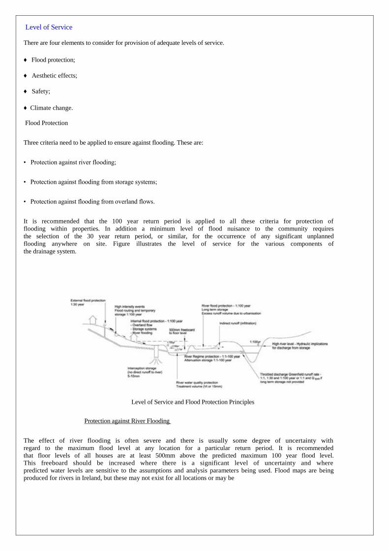
It is recommended that the 100 year return period is applied to all these criteria for protection of
flooding within properties. In addition a minimum level of flood nuisance to the community requires
the selection of the 30 year return period, or similar, for the occurrence of any significant unplanned
flooding anywhere on site. Figure illustrates the level of service for the various components of
the drainage system.
Level of Service and Flood Protection Principles
Protection against River Flooding
The effect of river flooding is often severe and there is usually some degree of uncertainty with
regard to the maximum flood level at any location for a particular return period. It is recommended
that floor levels of all houses are at least 500mm above the predicted maximum 100 year flood level.
This freeboard should be increased where there is a significant level of uncertainty and where
predicted water levels are sensitive to the assumptions and analysis parameters being used. Flood maps are being
produced for rivers in Ireland, but these may not exist for all locations or may be

Very approximate in their estimation. It is therefore important to investigate the likely accuracy of this information or
assess it specifically as part of the planning and design process.
In addition to floor levels of dwellings, other aspects such as access and the location of sensitive and important buildings
(hospitals) should also be designed taking into account flood risk.
In considering the maximum water level, appropriate precautions must be taken in assuming the scenarios which
might affect the level of flooding. These include:
• Current and proposed urban development upstream in the catchment;
• Throttles and other attenuation features upstream due to bridges and dams need to be specifically considered.
These may be removed over the course of time or may fail suddenly in flooding conditions;
• Floodplain storage upstream might be reduced.
A position needs to be taken on all these issues in determining maximum river water levels at any
site. These should be defined by the local authority for the area based upon the local area structure
plan or agreed with them in the early stages of considering a planning application. The general
position that should be taken is that man-made obstacles are likely to alter in time, but that natural
watercourse characteristics will be preserved by all future development. The level of future
development upstream and the runoff characteristics will depend on the local authority‟s views
regarding future development and the level of enforcement of SuDS techniques in that catchment
with its particular soil and topographic characteristics. This should not be limited to the structure plan
horizon which is often 20 years, though a longer term view of future development in the catchment
may be difficult to arrive at.
Occasionally river and sea defences result in embankments. The location of houses behind these
defences is a risk, which is a function of the water levels being restrained, the quality of the defense structure and the distance of the dwellings from the structure. There is limited guidance available for this situation, but it is important to carry out a risk analysis where this circumstance arises.
Storage Pond Flooding
Storage pond water levels are designed specifically, and therefore there is less uncertainty than for river flood water
levels. However property floor levels must be provided with a safety freeboard and it is recommended that this is 500mm.
There are a number of less obvious aspects to consider related to storage ponds. These are:
• Hydraulic constraints to the pond outlet;
• Overflow provision and risk of failure;
• Hydraulic backwater effects at the pond inlet.
High water levels downstream of the storage unit may affect the top water level in the pond. This is a complex issue of joint
probability (the river being high when the storage unit is full) and the relative levels of the water surfaces. A precautionary approach to the analysis should be assumed (possibly total dependency) to establish maximum storage water levels.

Similarly, flows into a storage unit which is full, may have a backwater issue for the inlet pipework
serving the development which might result in local flooding upstream. This is only relevant for quite
flat catchments, but generally this should not be too great a problem as the rainfall intensities in
events where the storage is fairly full are generally not those which cause a pipe capacity problem.
The failure of a storage unit, particularly if it is embanked, can be dramatic, even if it is a relatively small reservoir.
Reservoir design standards may be appropriate to consider in certain circumstances. Failure of the structure is
not the only thing to consider. Very extreme events, much larger than 100 years, can occur. The design of overflow
structures should be for a 200 year event and still providing a freeboard of at least 200mm.
Flooding from Overland Flow
Unlike the last two categories, which generally relate to long heavy rainfall periods, consideration
needs to be given to short very high intensity thunderstorm type events. These events, often lasting
for only 20 or 30 minutes, involve so much rainfall in this short period that the drainage system
cannot cope with the runoff. In this situation water runs off down roads and overland through
properties unless it is specifically taken into account. The impact of such events will generally be
much less for SuDS based systems which tend to be based on provision of volume (swales,
infiltration units etc).
Analysis of these situations requires careful examination of the topography of the proposed
development and the layout of the roads system. A model is best used in this situation, particularly where piped networks are involved, as flooding can occur at a low point due to the drainage system and its hydraulic characteristics as much as due to flooding down roads due to gully incapacity.
Sites should take into account topography to maximize the benefits of low points for storage and avoid placing vulnerable structures and/or properties in these areas.
Basements are particularly at risk in these situations and they should be protected by the ground being suitably profiled to prevent entry of overland flows.
An issue that should not be overlooked is that of responsibility for flood flows and the rehabilitation related to it.
In general it is advised that the drainage system should be designed to cater for the 30 year event without causing any
significant unplanned flooding, but that this should always be open to variation depending on the type of development
being served and the drainage system proposed.
Aesthetics
It may not be immediately obvious why aesthetics is a consideration of design. Although it does not lead to a primary
design criterion, the use of SuDS will require specific consideration of their visual impact. It will also draw attention
to the maintenance requirements and thereby the costs for operating the units. A negative view of SuDS units
will create problems in trying to get them generally accepted and used.
Safety
As with aesthetics, safety does not result in primary design criteria relating to the size of any unit. However the potential for
accidents and the measures needed to limit such incidences requires drainage engineers to specifically consider this issue.
Underground storage volume facilities, if used, must be designed for safe access for maintenance. This will influence the minimum
height within the structure, benching slopes, venting and other features. Drawdown facilities should be provided for all water
retaining structures.

Climate Change
Climate change is acknowledged as taking place the world over. The GDSDS Climate Change policy document advises
that rainfall event depths should be factored by 10% and that sea levels will rise by 400mm or more over the coming
century. There is no specific advice for river flow rates, but the Defra advice in UK suggests a 20% increase in flood
flows. The climate change policy also provides advice on the use of Time Series Rainfall.
If these criteria were not applied, and these predictions were found to be correct, then the level of
service provided by the drainage system would be less than it was designed to achieve. It is therefore advised that climate change criteria are applied for the design of drainage systems for new developments.
Climate Change Category Characteristics
River flows 20% increase in flows for all return periods up to 100 years
Sea level 400+mm rise (see Climate Change policy
document for sea levels as a function of return period)
Rainfall 10% increase in depth (factor all intensities by
1.1)
Modify time series rainfall in accordance with the GDSDS climate change policy document
Climate Change Factors to be Applied to Drainage Design
As a precaution it is advised that the same uplift is not applied to the calculated flow rates from green field runoff.
This provides a safety factor to the methodology. It can also be argued that the level of accuracy of the green field
runoff formula and prediction of river behavior warrants the addition of a safety factor anyway.
Other Design Issues
There are a few other issues which influence the generic design criteria discussed above. These are:
• Size of development;
• Environmental issues influencing storage design;
• Density of development;
• Location of development;
• Extending urban catchments.

Size of Development
To limit discharge to green field runoff rates usually requires a pipe or other form of throttle. These throttle sizes
theoretically need to be quite small to achieve the required maximum rate of flow, especially for small developments.
For operational purposes, it is recommended that the minimum throttle size for a pipe should be 150mm minimum
diameter and any other orifice unit other than a pipe should be a minimum of 200mm diameter. This means that flows
much below 10 l/s are rarely achievable. Thus small sites, by default, are often allowed a more generous discharge
limit than larger developments. This can be partially re-dressed in three ways.
The first is to ensure the development area is planned on a catchment basis so that any development fits within
a drainage strategy for a catchment.
Secondly building storage tanks and ponds in series can help in minimizing peak flow rates.
Thirdly certain SuDS systems can result in significantly greater attenuation than just using a tank and orifice
arrangement. Thus small sites should place particular emphasis on the use of unlined pervious pavements and
infiltration units. Where the permeability of a soil is low and the use of infiltration is marginal, it should still be
used, but systems should be designed with overflows to ensure against a level of service failure.
Density of Development
The drainage of any development, whatever size or location, should consider the opportunity to use appropriate SuDS
techniques. However situations will exist where there will be limited opportunity to use SuDS or infiltration methods.
Very high-density developments, usually planned for areas adjacent to primary traffic corridors of a city, may
have very limited opportunity to use SuDS techniques. Specific consideration of using SuDS units should always be
carried out, (and there are few circumstances where pervious pavements cannot be used), but it is possible that the use of
a traditional pipe drainage system, with storage tanks (concrete or high cellular voids systems), may be the most
appropriate drainage method to use.
Location of Development
There is a situation which is not really applicable to the generic approach described earlier. Developments that
are proposed at the downstream end of a catchment, by definition, do not have to be concerned with worsening the river
state downstream. In this situation, it may not be necessary to provide either “long term” storage or attenuation storage.
Similarly issues such as river erosion might also not be applicable. Water quality may therefore be the only principle
that needs to be considered in terms of the receiving water
Greenfield Developments and Infill Developments
New developments can take place in green field or Brownfield locations. In theory design criteria need not be any
different between these two situations. However, in practice, the precedent of existing high runoff rates from a previously developed site and the political and environmental value of re-using urban areas, often results in more liberal criteria being applied to these sites.
The contrary argument to this is that in locations where the urban drainage systems are particularly taxed (as would be
demonstrated by frequent flooding or high spill frequencies from CSO‟s on combined systems), then onerous criteria
will need to be applied to prevent existing levels of service reducing further. The choice of appropriate design criteria
is a matter for the local authority to consider in the light of the current situation and flood risk downstream.
Summary of Design Criteria
Table summarises the design criteria for the design of drainage systems. In principle these
criteria should be applied to all sites, but certain practical limitations (throttle sizes for achieving low
flow rates) and minimal consequences of non-compliance (draining to the estuary or coast) mean
that an intelligent approach should be taken in applying these criteria. These criteria are explained
further in Appendix E.
Climate change needs to be applied to all relevant elements of the design parameters used. Figure.

Criteria
Sub-
criterion
Return
Period
(Years)
Design Objective
Criterion 1 1.1 <1 Interception storage of at least 5mm, and preferably 10mm, of rainfall where
River water quality protection runoff to the receiving water can be prevented.
1.2 <1 Where initial runoff from at least 5mm of
rainfall cannot be intercepted, treatment
of runoff (treatment volume) is required.
Retention pond (if used) to have
minimum pool volume equivalent to 15mm
rainfall.
Criterion 2 2.1 1
River regime protection
Discharge rate equal to 1 year
greenfield site peak runoff rate or
2l/s/ha, whichever is the greater. Site
critical duration storm to be used to
assess attenuation storage volume.
2.2 100 Discharge rate equal to 1 in 100 year
greenfield site peak runoff rate. Site
critical duration storm to be used to
assess attenuation storage volume.
Criterion 3 3.1 30No flooding on site except where
Specifically planned flooding is Level of
service (flooding) for approved. Summer design
storm of 15 the site or 30 minutes
are normally critical.
3.2 100 No internal property flooding.Planned
flood routing and temporary
flood storage accommodated on site for
short high intensity storms. Site critical
duration events.
3.3 100 No internal property flooding.
Floor levels at least 500mm above
maximum river level and adjacent on-
site storage retention.
3.4 100 No flooding of adjacent urban areas.
Overland flooding managed within the
development.

Criteria
Criterion 4
River flood protection
(criterion 4.1, or 4.2 or 4.3 to be
applied)
Sub-
criterion
4.1
Return
Period
(Years)
100
Design Objective
“Long-term” floodwater accommodated on
site for development runoff volume which
is in excess of the greenfield runoff
volume.
Temporary flood storage drained by
infiltration on a designated flooding area
brought into operation by extreme events
only.
100 year, 6 hour duration storm to be used
for assessment of the additional volume of
runoff.
4.2 100 Infiltration storage provided equal in
volume to “long term” storage.
Usually designed to operate for all
events.
100year, 6 hour duration storm
to be used for assessment of the
additional volume of runoff.
4.3 100 Maximum discharge rate of QBAR or 2
l/s/ha, whichever is the greater,
for all attenuation Storage where
separate
“long term” storage cannot be
provided.
Criteria for New Development Drainage
This process should be an integral part of design.
Hydraulic Design of Drainage Components - General
The design of a storm sewer network and determining its performance requires the use of network modeling tools,
rainfall information based on the Flood Studies Report (FSR) and detailed network and ground level information. As
climate change is now accepted as taking place, a precautionary position has been taken to cater for its effects. Details
of these allowances are contained in the Regional Policy on Climate Change.
The design of a storm water drainage system is expected to involve the use of SuDS. However in nearly all situations,
pipes will also be involved to provide much of the conveyance of the runoff. The attenuation aspects of SuDS, together
with the perception of possible premature failure of SuDS, need to be taken into consideration in the design of the
supporting pipe system. Risk of sewer system failure can be due to:
• Structural failure;
• Pipe sedimentation / blockage;
• Inadequate capacity.
Design of sewers must therefore consider design for:

• Construction details;
• Velocity (to avoid sedimentation);
• Hydraulic capacity;
• Predicted performance using a simulation model.
Issues relating to pipe materials and the structural and construction requirements of drainage
systems are addressed in Chapter 7. The following sections address the hydraulic issues of pipe
design.
Design aspects relating to both SuDS design and quantifying site discharge constraints are also provided.
General Issues Related to Drainage Design
Site Constraints
Pipe work routing and levels are often determined by site constraints, including topography (and the need to maintain cover to pipes whilst not entailing excessive excavation), other services and contaminated ground. All site
constraints should be identified as soon as possible in the design process including areas of site not available due to temporary works.
By definition storage tends to be located towards the lower parts of the site. Flooding and overland flood routing can
occur at any point of the site, but will then migrate towards low points. Due consideration of the space requirements for such issues needs to be given in the initial stages of the site layout and design.
Services Conflict
Foul and storm water drainage are just two of the many services laid in the roads and footpaths in a new development.
Care should be taken to ensure that services do not conflict. Most of the other services are placed above the sewers and
therefore there is generally little risk of conflict.
Problems of level between the two sewer systems are also normally avoided as storm water pipes
are generally laid at flatter gradients than foul sewers. In general foul systems are therefore deeper
than storm water networks. Where steep catchments dictate pipe gradients, it is again preferable to
put foul sewers below storm pipes; this both minimizes the risk of foul pollution in the storm water
system and minimizes trench depths for the larger pipes, making it cheaper to construct.
In general it is considered good practice not to have the foul and surface sewer in the same trench above each other. This
causes obvious problems at manholes. The use of a single wide trench with the surface sewer off-set, benched at a
different level, tends to cause more problems to build than digging a separate trench.
Temporary Drainage
The need for temporary site drainage during the construction phase should be considered. This can take the form of
temporary ditches or the use of the designed storage system as long as reinstatement of these units is carried out at the
end of the contract.
Settlement tanks or ponds will be required to prevent pollution of watercourses and siltation of existing drainage
systems. Poor control of silt during construction can cause premature failure of infiltration systems. Consideration
should be given to the use of a temporary drainage system until the development is complete and vegetation established.

Safety and Design
Design has a direct bearing on the Health and Safety risk for the construction, operation and
dismantling of any structure. A significant category of Health and Safety concern is the collapse of
trenches. However there is a whole range of possible hazards and thought should be given to
considering what hazards exist. Once a hazard has been established and the level of risk estimated,
efforts should be made to minimize or remove the hazard by posing appropriate questions.
-Can the design be changed to avoid the risk?
-Can the design be modified to reduce the risk - combat at source?
- What controls can be applied to reduce the risk to an acceptable level (minimal or low)?
This process should be an integral part of design.
Drainage Separators
Although rarely an issue for new residential development, separators will normally be required for certain commercial and industrial sites to address runoff polluted with light oils, heavy oils or grease.
Currently BS 8301 Building Drainage: 1985 provides guidance on the use of these units and this will
be replaced by the European Standards when they are issued. The Environment Agency UK also
provides guidance. They have produced a series of documents entitled Pollution Prevention
Guidelines. PPG3 is “The use and design of oil separators in surface water drainage systems”. This
document itemizes sites that normally do and do not require oil separators, gives general design
criteria and a method for calculating separator size based on 6 minutes retention and catchment
area.
Storm water Pipe Design
Pipe Sizing for Standard Storm water Networks
Design of surface water pipes, particularly small systems of up to 450mm diameter pipes, is often carried out using
the Rational Method or the Modified Rational Method. They are normally subsequently analyzed using a
hydrograph method to check for flooding performance. Alternatively approximate pipe sizes can be quickly determined
for small sites by using a rule of thumb approach of assuming a constant rainfall intensity of 50mm/hr.
Whatever approach is used to size pipes, this should only be done to provide an initial assessment of the network, and
more detailed analysis should be carried out to justify/modify the pipe sizes and gradients to ensure an adequate level
of service. This normally requires simulation modeling to enable an assessment of the flood risk for extreme events.
Table summarize the criteria which apply to the Dublin region.

Parameter Surface Water Sewers
Minimum depth 1.2m cover under highways
0.9m elsewhere
Maximum depth Normally 5m
Minimum sewer size 225mm
Runoff factors for pipe sizing 100% paved and roof surfaces
0% off pervious surfaces
Rainfall for initial pipe sizing 50mm/hr rainfall intensity
Minimum velocity (pipe full) 1.0m/s
Flooding Checks made for adequate protection *
No flooding for return period less than 30 years except where
explicitly planned
Simulation modeling is required for sites greater than
24ha**
Roughness - ks 0.6mm
Surface Water Design Criteria
Private Sewers (those not vested)
Sewers serving individual properties can be 100mm. However pipe sizes and gradients are based on pipe capacity and velocity dictated by the criteria in Table 6.4.
Minimum cover to pipes can be reduced to 900mm when under lightly trafficked areas such as driveways, though this is
very much a function of pipe material and vehicle loadings. In other circumstances cover should not be less than 600mm
unless suitably protected.
Minimum Pipe Size and Gradient
The concept of pipe full design criterion is largely redundant in practice, as flooding is usually the controlling criteria. The use
of pipe full criterion helps guide the designer in achieving pipe sizes which are likely ensure this condition. Although
simulation modeling is not required for sites less than 24ha, flooding can only be predicted using computer simulation. The
development of very small sites may not warrant the expense of assessing flooding.
Roughness
Guidance on the roughness of sewers for various materials is based on work carried out at HR Wallingford (1982).
Guidance on pipe roughness is more fully advised in “Tables for Hydraulic design of pipes, sewers and channels” - volume 1,
6th edition from HR Wallingford.

Roughness and Velocity
CIRIA report 141 “Design of sewers to control sediment problems” has been produced to provide an
alternative design approach based upon the solids carrying capacity of flows in sewers. This is
applicable to both foul and surface water sewer design. It allows sewer gradients to be designed
specifically for sediment loads for any pipe size. It is important to note that self-cleansing velocities
increase with increasing pipe size. Very large sewers require high self-cleansing velocities (in
excess of 3 m/s). Large sewers (those in excess of 1m diameter) should therefore be designed to
allow a small amount of sediment deposition and should be specifically analysed using CIRIA report
141.
Runoff
Although the Wallingford Procedure uses a different runoff model to the fixed rates given in Table
in practice this is not a particular issue as the runoff volumes tend to be fairly similar for normal urban environments. Figure illustrates the differences between the two models and shows that, for fairly high development densities, the
assumptions in Table 6.4 of 100% and 0% runoff for paved and pervious areas respectively are conservative in predicting volumes of runoff.
Attenuation Storage Design
This section details the methods and equations to be used to enable the determination of storage volumes for
development sites.
The approach should always involve the use of a hydrograph method. Time series rainfall (TSR) is
theoretically better than design events, particularly for frequent event criteria, as a complex mix of
SuDS units will have runoff characteristics which will not be accurately reflected by the use of design
storms. However, the computational effort, and the lack of an extended series suitable for any
particular region, makes this approach relatively impractical. So although design events will be the
normal approach for system design and analysis, where a suitable time series exists, a check on the
system performance is recommended. Empirical design rules also exist for sizing certain SuDS
items.
The method for finding the storm water attenuation volume is:
Step 1:-Find the green field peak runoff rate for the site;
Step 2 :-Apply this rate as a throttle to the model of the development and run it with a range of duration events for design return periods in accordance with the design criteria.
Assessment of the storage requirement using models is normally carried out by applying the maximum discharge
flow rate as the discharge limit. This method provides a reasonable estimate of the volume needed. However depending
on the configuration and design of the storage system, this will under-predict the volume by as much as 20 or 30% due to
the variable head-discharge curve for any throttle if this is not represented in the model. Thus it will be important to
be aware of the potential under-prediction and to prove the adequacy of the storage provision at the detailed design
stage by building an accurate model which takes into account the depth-storage relationship together with the
head-discharge relationship of the unit.
Assessment of Greenfield Site Rate of Runoff
There are numerous hydrological techniques currently in use to estimate green-field runoff rates.
This section briefly reviews the techniques most commonly used by drainage engineers. Most of
these methods have been developed in the UK, but they are considered applicable to Ireland. (The
exception is the Rational Method, which in its original formulation is generally acknowledged to have been defined by an Irishman, Mulvaney). The methods include:
• Agricultural Development and Advisory Service, Report 345 (ADAS) (1982);
• Techniques based on the Rational Method
• Prudhoe and Young, Transport and Road Research Laboratory, Report LR 565, (TRRL, 1973);
• Flood Studies Report (FSR) statistical and rainfall runoff
- Various methods (National Environment Research Council, 1975);

• Flood estimation for small catchments, Report no. 124 (Institute of Hydrology, 1994);
• Flood Estimation Handbook (FEH) (Institute of Hydrology, 1999).
The last method is mentioned due to its importance in the UK. However it has no applicability in
Ireland as it is based on multiple regression characteristics for every location (1 km grid) across the
UK, and therefore is not discussed further. Its only relevant feature is that the FEH rainfall analysis
of data for UK has resulted in some significant changes in rainfall depths for various durations and
return periods compared with FSR. This implies that the FSR values for Ireland might be equally in
need of correction.
The proposed method used for determining peak flow rates for small green field catchments is IH Report 124, Flood
estimation for small catchments. A direct comparison between this method and the ADAS 345 method, which is also
commonly used in UK, is not easy, due to the different parameters used, but in general the differences have been
found to be relatively small for most typical catchments. The other methods are thought to be less appropriate.
In theory FSR-based methods are limited to catchments greater than 50 ha while the ADAS method is only to be applied to catchments which are smaller than 30 ha. However for simplicity it is proposed that Report 124 is applied to all catchment sizes by applying it to a 50ha site and linearly interpolating the result for smaller areas.
Agricultural Development and Advisory Service (ADAS) Report 345 Techniques
The Agricultural and Development Advisory (ADAS) Report 345, produced in 1982, details a technique which is primarily aimed at providing information to determine the size of pipes required for field drainage systems. This is an important distinction as the attenuation process of soil percolation will reduce the catchment response rate. The method is based on measurements taken on a number of small rural catchments.
The equation to estimate runoff from a site is of the form: Q = STFA
Where:
Q is the peak flow in l/s.
ST is the soil type factor, which ranges between 0.1 for a very permeable soil to 1.3 for an impermeable soil.
F is a factor, which is a function of average slope, maximum drainage length and average annual rainfall. The F number can be estimated from a nomograph included in the ADAS report.
A is the area of the catchment being drained in hectares.
Guidance on the values of the above variables is given in the ADAS report, together with a
nomograph that can be used to estimate the flow. The predicted peak flow resulting from the ADAS
equation for “grass” should be taken as being the one year return period flood and not the mean
annual flood for the catchment. The other 2 curves represent the return periods of 5 and 10 years.
Flow rates for higher return periods can then be calculated by using the appropriate regional growth
curve.
Assessment of Development Runoff Rate
Runoff from positively drained paved areas is effectively instantaneous by comparison with
green field runoff. The runoff rate therefore reflects the intensity of rainfall with a little attenuation
being provided by the filling of depression storage, surface runoff routing and pipe routing. This is
true for all high intensity short storms up to around 20 to 30 year return period events. Above this
return period, short duration “summer” storms have intensities which are so great that temporary
flooding takes place due to the inadequate capacity of the pipe system and gullies to cope with the volume of water. It
is therefore unimportant to determine peak flow rates from the site for evaluating the volume site storage.

Long term” Storage Design
The objective of providing “long term” storage is to protect the river from effects of the increased volume of runoff compared to green field conditions. Peak flow rates are addressed by the use of attenuation storage, but it is also important to minimize the additional volume of runoff created by the development.
As discussed earlier, the primary aim is to protect the river at times of flooding, and therefore this
long-term storage volume need not be mobilized for small events. Although relatively difficult to
design to operate in this way, (together with the additional uncertainty of design storms representing
all real storms), it is possible to design long term flood storage areas which come into effect for
larger events and only drain by infiltration. This volume can be quite large depending on the
catchment soil type and density of development, so flooding of the “long term” storage unit(s) needs
to start taking place at return periods significantly less than 100 years to ensure the volume retained
at the 100 year event meets the criteria. Therefore consideration must also be given to meeting
levels of service criteria.
Alternatively, and more simply, this volume can be provided in the form of infiltration volume around the site which
comes into effect for all events. In this case it is particularly important that the soil characteristics and water table
levels are suitable as there must be a reasonable expectation that much of this storage volume is available for an
extreme event.
To determine a storage volume requires the selection of event duration for the 100 year return
period. Six hours has been selected as the duration of the design event to compute the additional
storage. In theory, the river should be protected for its critical duration at the point of the
development. However for simplicity and practicality it is proposed to use a duration which is
appropriate for shorter rivers. This is not only relevant for those in the Dublin Region, but also it is
these smaller rivers which are going to be more sensitive to the effects of development runoff.
The estimation of the “long term” storage volume is a simple calculation of finding the difference between the runoff
volume generated by the development site and that for the green field site using the 100 year 6 hour event.
Assessment of Development Runoff Volumes
There are two Wallingford Procedure runoff models which are based on statistical correlation and the fixed
percentage runoff model usually used when applying the Rational Method. The two Wallingford Procedure runoff
models are described in Appendix D.
Although the Wallingford Procedure New UK PR equation is generally regarded as the most appropriate runoff
model for simulation modeling, there are certain situations, particularly for
developments in areas with SOIL type 4 (clay), where it will actually predict less runoff for extreme
events than the formula used for predicting green field runoff volume (FSSR 16, FSR Rainfall Runoff
Model Parameters Estimate Equations Updated, December 1985). Intuitively this seems unlikely, as
paved surfaces have around 70 to 80 percent runoff, whereas the FSR analysis cannot give values
much greater than around 55 percent. There are a number of arguments which can be made to
support the Wallingford Procedure runoff model. The main one is that the land form in urban areas is
heavily modified with many obstructions (garden walls, buildings, undrained low points) which
prevent runoff from occurring from some paved and unpaved surfaces. However for simplicity and
taking a precautionary position, it is proposed that a fixed runoff model for the paved surfaces and
an allowance for runoff from the previous surfaces, that is consistent with the analysis for the
Greenfield runoff volume approach, is used.
It is proposed that an 80% runoff is assumed for impervious surfaces and the SPR value of the soil is assumed for the
pervious area based on the local soil type.
Assessment of Greenfield Runoff Volumes
The estimation of runoff volume from pervious areas using FSSR 16 is detailed in Appendix D.
However this closely approximates to an assumption that runoff volume is equal to the SPR value for
the soil type. Table 6.7 summaries the SPR value for the 5 soil types used in the FSR procedure.

SPR value SOIL
(% runoff)
1 0.1
2 0.3
3 0.37
4 0.47
5 0.53
Table SPR Values for SOIL (pervious surface runoff factor
Retention / Detention Ponds and Tanks
These types of storm water units are aimed at providing storage and attenuation and some degree of treatment. The design
of ponds and tanks uses the inflow/outflow hydrograph process. The actual volume required is defined by a matrix of
parameters that are summarized as:
• Depth / area storage relationship;
• Head / discharge relationship;
• Throttle rate;
• Effective contributing area;
• Rainfall characteristics of the area;
• Level of service;
• Safety.
Some of these aspects have been addressed earlier and are therefore not discussed here. The hydraulic design
requirements are considered below. Other aspects (safety for instance) are dealt with in the Environmental Management
Policy document.
Depth / Area Storage Relationship
The depth / area storage function is largely dictated by topography and outfall levels. However other issues such as treatment processes in ponds will dictate depth requirements. Volumetric allowances for vegetation should also be
provided for in ponds, which might be as much as 20 percent for heavily vegetated systems.
Head / Discharge Relationship
Structures are normally designed to a specified maximum discharge rate and this is usually achieved when the storage
structure is full. This means that the outflow at lower water levels is passing less flow forwards making the effective
volume needed larger, but theoretically approximately reflects the increasing green field peak flow rates for lesser events.
This additional volume requirement can often be minimized by having the storage structure as an off-line pond, but
this has disadvantages for water quality treatment. As this criteria involves 3 flow rates (1, 30 and 100 year return
periods), analysis for attenuation storage needs to be carried out in 3 stages.
This analysis could result in the use of 3 orifices to achieve a good fit to the discharge requirements for the 3 return
periods. In practice it should result in 1 low level orifice and a second outlet which might be an orifice or slot of some
kind. It is important to make sure the final design is practical as well as effective. The flow rate control system should
aim to approximate to the calculated system, but common sense must be exercised in finding the most practical solution.
Storage systems are often located near the river to which they discharge. River levels will provide backwater effects,
which will modify the discharge at times of high water levels. This has been discussed in some detail earlier.
Throttle Sizes and Discharge Rate
There are practical difficulties in meeting hydraulic criteria for very low flow rates, as local authorities rarely take in

charge orifice controls or pipe sizes with diameters less than 150mm. Although there are vortex devices which can
reduce the flow through a throttle unit, but still provide a free bore of 150mm, developments below a certain size will not
be able to throttle the flow sufficiently to meet the stated criteria. For example if 2l/s/ha is used for the 1 year throttle rate,
and the minimum flow rate is considered to be 10l/s, then the minimum drainage area served is 5 ha.
This criterion for minimum orifice size, although a constraint for the authorities, need not necessarily apply to private
owners. Systems such as pervious pavements, due to the very limited risk of obstruction, can be designed with
orifice sizes of 75mm or even smaller.
This constraint draws attention to two aspects of good drainage practice. The first is that areas should be drained in
an integrated manner, so that even if a single developer is only developing a 1ha site, it should fit into a larger drainage
strategy. The second is that this element of storage may be better achieved by other drainage components,
particularly those which have slow release characteristics for “small” events. SuDS units such as lined or unlined
permeable pavement car parks or under-drained swales can provide low discharge rates.
Filter Drains
Filter Drains are trenches adjacent to roads with flows passing into the soil from a trench filled with a coarse stone mix. A
perforated pipe usually passes along the length of the trench, to ensure water levels are kept well below the road subbase.
The depth of the trench below the perforated pipe can be selected to meet storage design requirements.
In wet winter conditions if the soil is saturated, it is likely that Filter trenches will work in reverse acting as drainage
systems, contributing to runoff. The assessment of their hydraulic design performance both in terms of attenuation
and runoff reduction is therefore site specific.
Flooding of Public Open Spaces
Infiltration in public open spaces is not a recognized SuDS system, but is included to represent those areas where flooding
is planned to take place only in extreme events to deal with either overland flooding or “long term” storage.
Parks and other types of open spaces need to be carefully contoured and provided with suitable
under-drainage to ensure they dry out effectively. However, to comply with the principles of long-
term storage, it is important that this is not rapid and therefore not connected directly to the main
drainage system.
Design Requirements
Developers should continue to provide particular design details and parameters for large residential, commercial,
industrial and institutional developments
Design criteria for stormwater drainage for both runoff attenuation and reduction should be used for drainage
design for New Developments

CASE STUDY
FOR TYPE – A
PLOT AREA= 145.15 M2
BULT UP AREA 40% = 58.06 M2
GARDEN AREA = 10% OF TOTAL PLOAT AREA =14.51 M2
PAVMENT= IN BALANCE AREA
RAINFALL IN AREA = 20CM IN MONSOON
EVAPORATION LOSS =10%
PEOPOLATION THROUGH JOINTS OF REJID PAVMENT = 5%
REGID PAVMENT AT GROUND LEVEL = 145.15 – (58.06+14.51)
= 72.89 M2
TARECE AREA CONSIDRING 80% OF BUILT UP AREA = 0.8*58.06
= 46.448 M2
TOTAL AREA THROUGH WHICH RAIN WATER IS TO BE COLLECTED = 72.89 + 46.448
= 119.038 M2
TOTAL VOLUME OF WATER = 119.038 * 0.20
=23.80 M3
=23.80*1000
=23800 LIT
EVAPORATION 10% = 23800*0.1
= 2380 LIT
INFILTARTION LOSS =5%
=11900LIT
NET WATER TO BE COLLECTED = 23800-(2380+11900)
=9520 LIT

FOR TYPE – B
PLOT AREA= 186.95 M2
BULT UP AREA 40% = 74.78 M2
GARDEN AREA = 10% OF TOTAL PLOAT AREA =18.69 M2
PAVMENT= IN BALANCE AREA
RAINFALL IN AREA = 20CM IN MONSOON
EVAPORATION LOSS =10%
PEOPOLATION THROUGH JOINTS OF REJID PAVMENT = 5%
REGID PAVMENT AT GROUND LEVEL = 186.95 – (74.78+18.69)
= 93.48 M2
TARECE AREA CONSIDRING 80% OF BUILT UP AREA = 0.8*74.78
= 59.82 M2
TOTAL AREA THROUGH WHICH RAIN WATER IS TO BE COLLECTED = 93.48+59.82
= 153.3 M2
TOTAL VOLUME OF WATER = 153.3 * 0.20
=30.66 M3
=30.66*1000
=30660 LIT
EVAPORATION 10% = 30660*0.1
=3066 LIT
INFILTARTION LOSS =5%
=15330 LIT
NET WATER TO BE COLLECTED = 30660-(3066 + 15330)
=12264 LIT

FOR TYPE – C
PLOT AREA= 134.7 M2
BULT UP AREA 40% = 53.88 M2
GARDEN AREA = 10% OF TOTAL PLOAT AREA =13.47 M2
PAVMENT= IN BALANCE AREA
RAINFALL IN AREA = 20CM IN MONSOON
EVAPORATION LOSS =10%
PEOPOLATION THROUGH JOINTS OF REJID PAVMENT = 5%
REGID PAVMENT AT GROUND LEVEL = 134.7 – (53.88-13.47)
= 94.28 M2
TARECE AREA CONSIDRING 80% OF BUILT UP AREA = 0.8*53.88
= 43.10 M2
TOTAL AREA THROUGH WHICH RAIN WATER IS TO BE COLLECTED = 94.28+43.10
= 137.38 M2
TOTAL VOLUME OF WATER = 137.38 * 0. 20
=27.47 M3
=27.47*1000
=27470 LIT
EVAPORATION 10% = 27470*0.1
=2747 LIT
INFILTARTION LOSS =5%
=13735 LIT
NET WATER TO BE COLLECTED = 27470 – (2747 + 13735)
=10988 LIT

RAIN FALL COLLECTED FROM ROAD –
MAIN ROAD =75*6
=450 M2
SUB ROAD = 18*6
=108 M2
FOR MAIN ROAD
TOTAL VOLUME OF WATER THAT IS TOTAL RUNOFF = 450*0.20
=90M3
=90*1000
=90000 LIT
EVAPORATION 10% = 9000*0.1
=900 LIT
IN FILTRATION LOSS = 5%
= 45000 LIT
NET WATER TO BE COLLECTED = 90000 – (900 + 45000)
=44100 LIT
FOR SUB ROADS
TOTAL VOLUME OF WATER THAT IS TOTAL RUNOFF = 108*0.20
=21.6 M3
=21.6*1000
=21600 LIT
EVAPORATION 10% = 21600*0.1
=2160 LIT
IN FILTRATION LOSS = 5%
= 10800 LIT
NET WATER TO BE COLLECTED = 21600 – (2160 + 10800)
=8640 LIT

TOTAL VOLUME OF WATER IS TO BE COLLECTED FROM MAIN ROAD SURFACE =2*44100
= 88200 LIT
=88.2 M3
TOTAL VOLUME OF WATER IS TO BE COLLECTED FROM SUB ROAD SURFACE =3*8640
= 25920 LIT
=25.92 M3
TOTAL WATER IS TO BE COLLECTED FORM ROAD = 88200 + 25920
=114120 M3

NO. OF TYPE – A HOUSE =26
NO. OF TYPE – B HOUSE =4
NO. OF TYPE – C HOUSE =10
NET WATER COLLECTED FROM TYPE – A HOUSE = 26*9520
=247520 LIT
NET WATER COLLECTED FROM TYPE – B HOUSE = 4*12264
= 49056LIT
NET WATER COLLECTED FROM TYPE – C HOUSE = 10*10988
= 109880LIT
TOTAL WATER IS TO BE COLLECTED FROM ALL HOUSES= 247520 + 49056 + 109880
= 406456 LIT
TOTAL WATER COLLECTED FROM ROAD & HOUSES= 406456 + 114120
=520576 LIT
DESIGN OF UNDERGROUND WATER TANK TANK CAPACITY = 520576 LIT
M25 GRADE CONCRETE
DEPTH OF TANK IS = 9 M
THICKNESS OF TOP SLAB = 0.2 M
FREE BOARD = 0.3 M
WATER DEPTH = 9 – (0.2 + 0.3)
= 8.5M
VOLUME OF TANK = 520576/1000
=520.576 M3
VOLUME OF TANK = ∏/4 * D2 * h
520.576 = ∏/4 *D2 * 8.5
D = 8.85 M