stresses of the earth-crust according to the …modelling of the horizontal strains and oke stresses...
TRANSCRIPT
191
Geo
dets
ki v
estn
ik 4
9/20
05 –
2IZ
ZN
IZ Z
NIZ
ZN
IZ Z
NIZ
ZN
AN
OS
AN
OS
AN
OS
AN
OS
AN
OS
TI
IN S
TI
IN S
TI
IN S
TI
IN S
TI
IN S
TR
TR
TR
TR
TR
OK
EO
KE
OK
EO
KE
OK
EMODELLING OF THE HORIZONTAL STRAINS ANDSTRESSES OF THE EARTH-CRUST ACCORDING TO THE
DATA OF GEODETIC MEASUREMENTSMODELIRANJE HORIZONTALNIH DEFORMACIJ IN NAPETOSTI ZEMELJSKE SKORJE
PO PODATKIH GEODETSKIH MERITEV
Algimantas Zakarevičius, Česlovas Aksamitauskas, Arminas Stanionis
KLJUČNE BESEDE
finite element method, GPS, geodynamicprocesses, tectonic stresses, deformations of theEarth-crust.
UDK: 519.63:528.28:551.2 Klasifikacija prispevka po COBISS-u: 1.02
POVZETEK
Raziskavo smo izvedli z aplikacijo Hookovegafizikalnega zakona za opisovanje razmerja medhorizontalnimi deformacijami in geodinamičniminapetostmi zemeljske skorje. Na območjugeodinamičnega poligona nuklearne elektrarneIgnalina so bile izvedene eksperimentalne meritve.Pridobili smo nove podatke o spremembahgeodinamične napetosti, ki so bistveno povezane stektonsko strukturo območja. Po analizi ingeneralizaciji pridobljenih rezultatov so se določilespremembe tektonskih napetosti v bližinigeodinamičnih tal nuklearne elektrarne Ignalina innjihove povezave s tektonsko strukturo. Na koncuugotavljamo, da se Hookov zakon, z opisovanjemrazmerij med horizontalnimi deformacijami zemeljskeskorje in geodinamičnimi napetostmi, lahko praktičnouporabi za presojo zakonitosti spremembgeodinamičnih napetosti.
KEY WORDS
ABSTRACT
The study was carried out by applying the Hooke’sphysical law – to describe the relationship of thehorizontal strains and geodynamic stresses of theEarth-crust. Experimental studies were carried out inthe territory of the geodynamic polygon of the IgnalinaNuclear Power Plant. New data of geodynamic stresschanges that are significantly related with the tectonicstructure of the territory were obtained. After theanalysis and generalization of results obtained, thechange of tectonic stresses in the surroundings of thegeodynamic ground of the Ignalina Nuclear PowerPlant and its connections with tectonic structure weredetermined. The conclusion is drawn that Hooke’s law,by describing the relations between horizontal strainsof the Earth-crust and geodynamic stresses, may beused practically and applied for estimating theregularities of the geodynamic stress change.
metoda končnih elementov, GPS, geodinamičniprocesi, tektonske napetosti, deformacijezemeljske skorje
1 INTRODUCTION
By studying the current horizontal movements of the Earth-crust by geodetic methods, themovements of geodetic points that are identified with movements of the Earth-crust are established.The movements of geodetic points are established according to the changes of coordinates withinthe certain period of time between geodetic measurements. Thus, the reading values of movements A
lgim
anta
s Z
akar
evič
ius,
Čes
lova
s A
ksam
itaus
kas,
Arm
inas
Sta
nion
is -
MO
DEL
LIN
G O
F TH
E H
ORI
ZON
TAL
STRA
INS
AN
D S
TRES
SES
OF
THE
EART
H-C
RUST
AC
CO
RDIN
G T
O T
HE
DAT
A O
F G
EOD
ETIC
MEA
SURE
MEN
TS
stevilka 2_05-beckup.pmd 18.6.2005, 21:56191

192
Geo
dets
ki v
estn
ik 4
9/20
05 –
2IZ
ZN
IZ Z
NIZ
ZN
IZ Z
NIZ
ZN
AN
OS
AN
OS
AN
OS
AN
OS
AN
OS
TI
IN S
TI
IN S
TI
IN S
TI
IN S
TI
IN S
TR
TR
TR
TR
TR
OK
EO
KE
OK
EO
KE
OK
E of the Earth-crust only in solitary points located sparsely are determined. When making modelsof deformations of the Earth-crust, the values of deformations in other points are determined inthe way of interpolation, by applying the procedures of rectilinear interpolation in most cases.Such method of determining the horizontal deformations of the Earth-crust has manyshortcomings. The measured values and directions of geodetic point movements depend on theselection of initial points that are considered stable when calculating movements. When calculatingthe values of movements of the Earth-crust in non-geodetic points in the way of geometricinterpolation, mechanical characteristics of the deformed body, i.e. mechanical model ofdeformations, are not estimated.
According to the laws of mechanics, movements of the Earth-crust are related to the change ofthe Earth-crust stresses. Therefore, there is a functional relation between movements and stressesof the Earth-crust [2, 3, 5, 7, 17, 23, 25, 32, 33]. Since the current movements of the Earth-crustare the continuation of tectonic deformations of the Earth-crust occurring for a long period oftime, the deformations determined by geodetic methods are the change of deformations of thelong period of time within the certain period of time. For this reason, according to the results ofgeodetic measurements, by using relations between strains and stresses, it is possible to determineonly the changes of stresses, but not the absolute values of stresses. However, by applying thedirect comparison of coordinates obtained in separate cycles of measuring to determine themovements of the Earth-crust, the results obtained may have more than one meaning. For thisreason, the changes of the Earth-crust stresses calculated according to the movements of geodeticpoints will have also more than one meaning (will be ambiguous).
Therefore, when modelling the horizontal strains of the Earth-crust and the changes of theEarth-crust stresses according to the results of geodetic measurements, it is necessary to applythe methods of analysis invariant with respect to the systems of coordinates (not depending onthe selection of initial points when calculating the movements of geodetic points). One of suchmethods is the tensor analysis of strains and stresses of the Earth-crust [2, 3, 11, 23, 25, 32].
When making the models of the change of the Earth-crust strains and the Earth-crust stressesrelated with them, it is necessary to combine tensor analysis with mechanical models of physicalbody deformations. The finite element method applied widely in mechanics to work on modellingproblems may be used for such combination when modelling the change of strains and stressesand estimating their values in the theory analysed. Thus, the detailed models of the change ofstrains and stresses of the Earth-crust may be obtained. These models reflect the relations betweenthe Earth-crust strains and tectonic structure of the territory better than values of deformationscalculated only in points matching with geodetic points.
The object of this study is to analyse the application of tensor analysis and finite element methodin modelling the horizontal strains of the Earth-crust and the change of the Earth-crust stressesaccording to the data of geodetic measurements and carry out studies by these methods in theIgnalina Nuclear Power Plant region.
Relative linear and shear horizontal strains, changes of normal and shear geodynamic stressesand changes of the principal stresses were calculated in the Ignalina Nuclear Power Plant regionAlg
iman
tas
Zak
arev
ičiu
s, Č
eslo
vas
Aks
amita
uska
s, A
rmin
as S
tani
onis
- M
OD
ELLI
NG
OF
THE
HO
RIZO
NTA
L ST
RAIN
S A
ND
STR
ESSE
S O
F TH
E EA
RTH
-CRU
ST A
CC
ORD
ING
TO
TH
E D
ATA
OF
GEO
DET
IC M
EASU
REM
ENTS
stevilka 2_05-beckup.pmd 18.6.2005, 21:56192
193
Geo
dets
ki v
estn
ik 4
9/20
05 –
2IZ
ZN
IZ Z
NIZ
ZN
IZ Z
NIZ
ZN
AN
OS
AN
OS
AN
OS
AN
OS
AN
OS
TI
IN S
TI
IN S
TI
IN S
TI
IN S
TI
IN S
TR
TR
TR
TR
TR
OK
EO
KE
OK
EO
KE
OK
Eby using changes of ground point coordinates, taking that the character of plane strains is isotropic.By using the physical relation between horizontal strains and stresses, new results were obtainedand the connection between the tectonic structure of the Ignalina Nuclear Power Plant regionand current geodynamic processes was estimated basing on these results. It was established thatthe structure of horizontal deformations of the Earth-crust and geodynamic stresses is relatedwith tectonic peculiarities of the territory in the Ignalina Nuclear Power Plant region, i.e. theterritory is also active in current period from the geodynamic point of view.
2 METHODS OF CALCULATING THE HORIZONTAL DEFORMATIONS
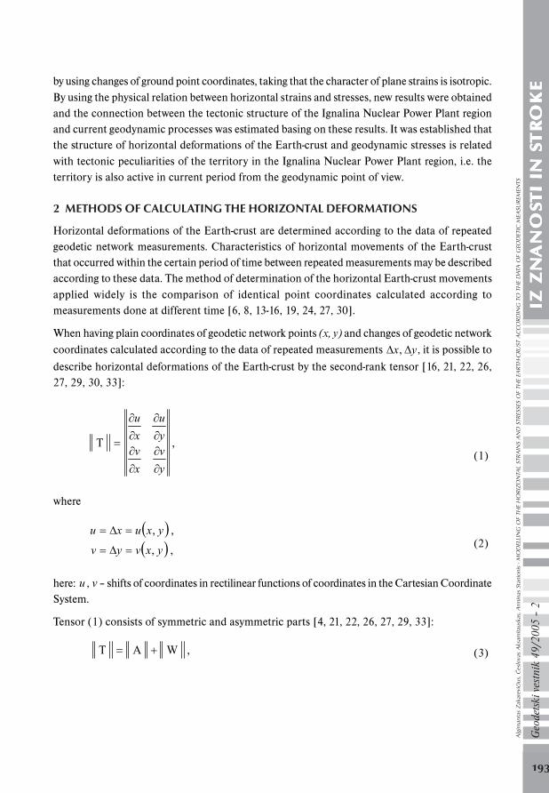
Horizontal deformations of the Earth-crust are determined according to the data of repeatedgeodetic network measurements. Characteristics of horizontal movements of the Earth-crustthat occurred within the certain period of time between repeated measurements may be describedaccording to these data. The method of determination of the horizontal Earth-crust movementsapplied widely is the comparison of identical point coordinates calculated according tomeasurements done at different time [6, 8, 13-16, 19, 24, 27, 30].
When having plain coordinates of geodetic network points (x, y) and changes of geodetic network
coordinates calculated according to the data of repeated measurements yx , , it is possible to
describe horizontal deformations of the Earth-crust by the second-rank tensor [16, 21, 22, 26,27, 29, 30, 33]:
y
v
x
vy
u
x
u
T , (1)
where
yxuxu , ,
yxvyv , , (2)
here: u , v – shifts of coordinates in rectilinear functions of coordinates in the Cartesian CoordinateSystem.
Tensor (1) consists of symmetric and asymmetric parts [4, 21, 22, 26, 27, 29, 33]:
W A T , (3)
Alg
iman
tas
Zak
arev
ičiu
s, Č
eslo
vas
Aks
amita
uska
s, A
rmin
as S
tani
onis
- M
OD
ELLI
NG
OF
THE
HO
RIZO
NTA
L ST
RAIN
S A
ND
STR
ESSE
S O
F TH
E EA
RTH
-CRU
ST A
CC
ORD
ING
TO
TH
E D
ATA
OF
GEO
DET
IC M
EASU
REM
ENTS
stevilka 2_05-beckup.pmd 18.6.2005, 21:56193
194
Geo
dets
ki v
estn
ik 4
9/20
05 –
2IZ
ZN
IZ Z
NIZ
ZN
IZ Z
NIZ
ZN
AN
OS
AN
OS
AN
OS
AN
OS
AN
OS
TI
IN S
TI
IN S
TI
IN S
TI
IN S
TI
IN S
TR
TR
TR
TR
TR
OK
EO
KE
OK
EO
KE
OK
E
,
2
1
2
1
2
12
1
2
12
1
A
2212
1211
y
v
x
v
y
u
x
v
y
u
x
u
yyxy
xyxx (4)
,
02
1
2
10
02
12
10
W
y
u
x
v
x
v
y
u
yx
xy (5)
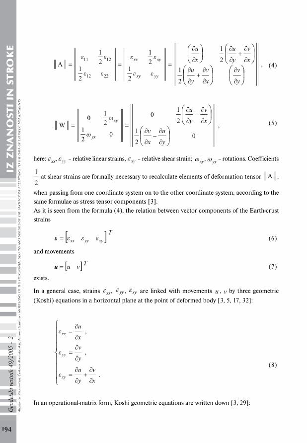
here: xx, yy – relative linear strains, xy – relative shear strain; xy, yx – rotations. Coefficients
2
1 at shear strains are formally necessary to recalculate elements of deformation tensor A ,
when passing from one coordinate system on to the other coordinate system, according to thesame formulae as stress tensor components [3].As it is seen from the formula (4), the relation between vector components of the Earth-cruststrains
Txyyyxx (6)
and movements
Tvu u (7)
exists.
In a general case, strains xx, yy , xy are linked with movements u , v by three geometric
(Koshi) equations in a horizontal plane at the point of deformed body [3, 5, 17, 32]:
.
,
,
x
v
y
u
y
v
x
u
xy
yy
xx
(8)
In an operational-matrix form, Koshi geometric equations are written down [3, 29]:
Alg
iman
tas
Zak
arev
ičiu
s, Č
eslo
vas
Aks
amita
uska
s, A
rmin
as S
tani
onis
- M
OD
ELLI
NG
OF
THE
HO
RIZO
NTA
L ST
RAIN
S A
ND
STR
ESSE
S O
F TH
E EA
RTH
-CRU
ST A
CC
ORD
ING
TO
TH
E D
ATA
OF
GEO
DET
IC M
EASU
REM
ENTS
stevilka 2_05-beckup.pmd 18.6.2005, 21:56194
195
Geo
dets
ki v
estn
ik 4
9/20
05 –
2IZ
ZN
IZ Z
NIZ
ZN
IZ Z
NIZ
ZN
AN
OS
AN
OS
AN
OS
AN
OS
AN
OS
TI
IN S
TI
IN S
TI
IN S
TI
IN S
TI
IN S
TR
TR
TR
TR
TR
OK
EO
KE
OK
EO
KE
OK
E
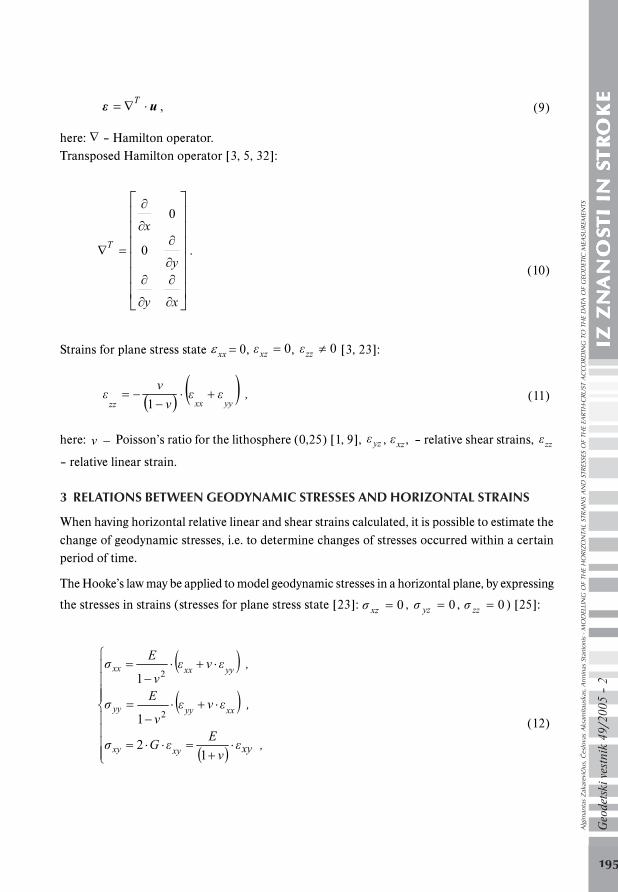
uT , (9)
here: – Hamilton operator.Transposed Hamilton operator [3, 5, 32]:
xy
y
xT 0
0
.
(10)
Strains for plane stress state xx 0, 0xz , 0zz [3, 23]:
,yyxxzz 1
(11)
here: − ν Poisson’s ratio for the lithosphere (0,25) [1, 9], yz , xz , – relative shear strains, zz
– relative linear strain.
3 RELATIONS BETWEEN GEODYNAMIC STRESSES AND HORIZONTAL STRAINS
When having horizontal relative linear and shear strains calculated, it is possible to estimate thechange of geodynamic stresses, i.e. to determine changes of stresses occurred within a certainperiod of time.
The Hooke’s law may be applied to model geodynamic stresses in a horizontal plane, by expressing
the stresses in strains (stresses for plane stress state [23]: 0xz , 0yz , 0zz ) [25]:
,E
G
,E
,E
xyxyxy
xxyyyy
yyxxxx
12
1
1
2
2
(12)
Alg
iman
tas
Zak
arev
ičiu
s, Č
eslo
vas
Aks
amita
uska
s, A
rmin
as S
tani
onis
- M
OD
ELLI
NG
OF
THE
HO
RIZO
NTA
L ST
RAIN
S A
ND
STR
ESSE
S O
F TH
E EA
RTH
-CRU
ST A
CC
ORD
ING
TO
TH
E D
ATA
OF
GEO
DET
IC M
EASU
REM
ENTS
stevilka 2_05-beckup.pmd 18.6.2005, 21:56195
196
Geo
dets
ki v
estn
ik 4
9/20
05 –
2IZ
ZN
IZ Z
NIZ
ZN
IZ Z
NIZ
ZN
AN
OS
AN
OS
AN
OS
AN
OS
AN
OS
TI
IN S
TI
IN S
TI
IN S
TI
IN S
TI
IN S
TR
TR
TR
TR
TR
OK
EO
KE
OK
EO
KE
OK
E
here: G – shear modulus, E – Young’s modulus for the lithosphere 2
10
m
N 107 [1, 9],
xx,
yy , zz – normal stresses, xy , , xz yz – shear stresses.
The factor 2 in Eq. (12) is sometimes omitted in literature [7, 23] as a consequence of thealready noted difference in the definition of the shearing strain.Physical dependencies (12) may be written down in a matrix form [17, 32]:
K , (13)
here
T
xyyyxx , (14)
K
2
100
01
01
1 2
E,
(15)
T
xyyyxx , (16)
here: – geodynamic stress vector, – vector of the horizontal Earth-crust strains, K – stiffnessmatrix.Following the law of shear stress duality [3, 25] yxxy . Accordingly, the geodynamic stress
state in a horizontal plane is defined by the symmetric stress tensor [2, 3, 5, 17, 25, 32]:
yyxy
xyxx~ . (17)
The second-rank stress tensor ~ is invariant with respect to the system of coordinates, i.e. itdoes not depend on the selection of coordinate system.The principal geodynamic stresses are calculated from the quadratic equation [3, 33]:
0212 II (18)
that is obtained by extending the determinant [2, 3]:
Alg
iman
tas
Zak
arev
ičiu
s, Č
eslo
vas
Aks
amita
uska
s, A
rmin
as S
tani
onis
- M
OD
ELLI
NG
OF
THE
HO
RIZO
NTA
L ST
RAIN
S A
ND
STR
ESSE
S O
F TH
E EA
RTH
-CRU
ST A
CC
ORD
ING
TO
TH
E D
ATA
OF
GEO
DET
IC M
EASU
REM
ENTS
stevilka 2_05-beckup.pmd 18.6.2005, 21:56196
197
Geo
dets
ki v
estn
ik 4
9/20
05 –
2IZ
ZN
IZ Z
NIZ
ZN
IZ Z
NIZ
ZN
AN
OS
AN
OS
AN
OS
AN
OS
AN
OS
TI
IN S
TI
IN S
TI
IN S
TI
IN S
TI
IN S
TR
TR
TR
TR
TR
OK
EO
KE
OK
EO
KE
OK
E
0 detyyxy
xyxx
yyxy
xyxx , (19)
yyxxI1 , (20)
2yyxy
xyxxI , (21)
here: – the principal stresses, 1I , 2I – stress tensor invariants.
After solution of quadratic equation (18), two actual roots 1 , 2 21
are obtained, i.e.
1 – the maximum principal stress, 2 – the minimum principal stress.
4 MODELLING OF HORIZONTAL STRAINS AND GEODYNAMIC STRESSES 2-D OFTHE EARTH-CRUST IN THE FINITE ELEMENT METHOD
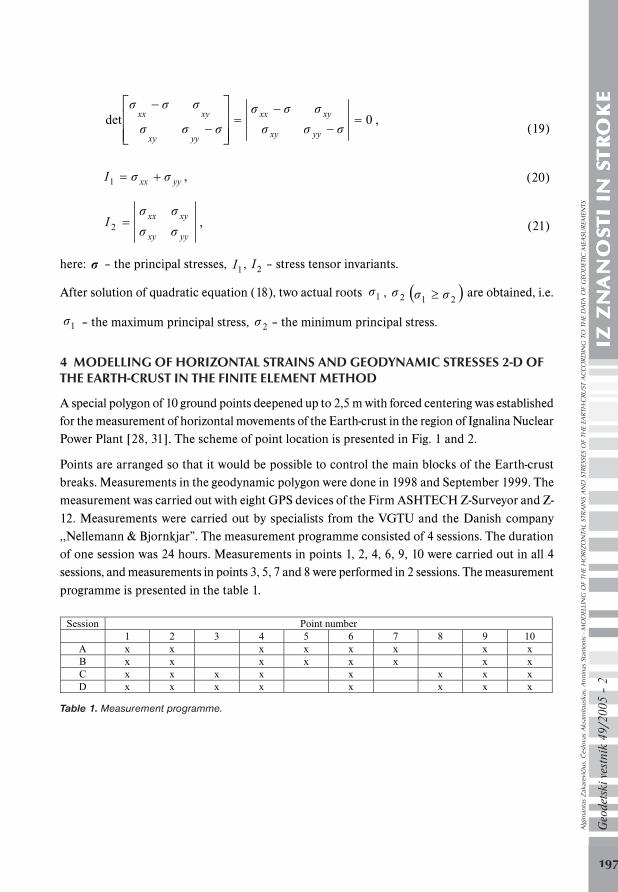
A special polygon of 10 ground points deepened up to 2,5 m with forced centering was establishedfor the measurement of horizontal movements of the Earth-crust in the region of Ignalina NuclearPower Plant [28, 31]. The scheme of point location is presented in Fig. 1 and 2.
Points are arranged so that it would be possible to control the main blocks of the Earth-crustbreaks. Measurements in the geodynamic polygon were done in 1998 and September 1999. Themeasurement was carried out with eight GPS devices of the Firm ASHTECH Z-Surveyor and Z-12. Measurements were carried out by specialists from the VGTU and the Danish company,,Nellemann & Bjornkjar”. The measurement programme consisted of 4 sessions. The durationof one session was 24 hours. Measurements in points 1, 2, 4, 6, 9, 10 were carried out in all 4sessions, and measurements in points 3, 5, 7 and 8 were performed in 2 sessions. The measurementprogramme is presented in the table 1.
Session Point number
1 2 3 4 5 6 7 8 9 10 A x x x x x x x x B x x x x x x x x C x x x x x x x x D x x x x x x x x
Table 1. Measurement programme.
Alg
iman
tas
Zak
arev
ičiu
s, Č
eslo
vas
Aks
amita
uska
s, A
rmin
as S
tani
onis
- M
OD
ELLI
NG
OF
THE
HO
RIZO
NTA
L ST
RAIN
S A
ND
STR
ESSE
S O
F TH
E EA
RTH
-CRU
ST A
CC
ORD
ING
TO
TH
E D
ATA
OF
GEO
DET
IC M
EASU
REM
ENTS
stevilka 2_05-beckup.pmd 18.6.2005, 21:56197
198
Geo
dets
ki v
estn
ik 4
9/20
05 –
2IZ
ZN
IZ Z
NIZ
ZN
IZ Z
NIZ
ZN
AN
OS
AN
OS
AN
OS
AN
OS
AN
OS
TI
IN S
TI
IN S
TI
IN S
TI
IN S
TI
IN S
TR
TR
TR
TR
TR
OK
EO
KE
OK
EO
KE
OK
E
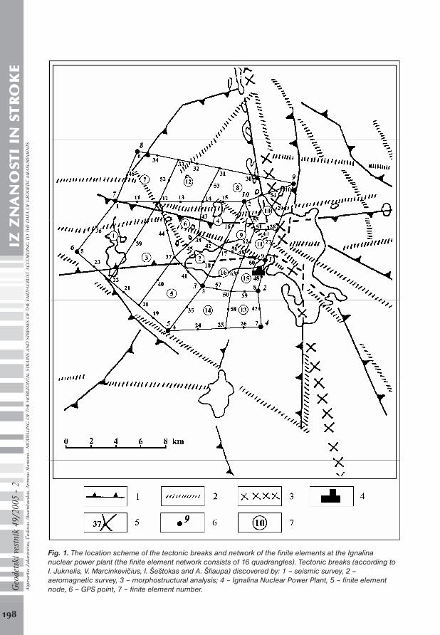
Fig. 1. The location scheme of the tectonic breaks and network of the finite elements at the Ignalinanuclear power plant (the finite element network consists of 16 quadrangles). Tectonic breaks (according toI. Juknelis, V. Marcinkevičius, I. Šeštokas and A. Šliaupa) discovered by: 1 – seismic survey, 2 –aeromagnetic survey, 3 – morphostructural analysis; 4 – Ignalina Nuclear Power Plant, 5 – finite elementnode, 6 – GPS point, 7 – finite element number.
Alg
iman
tas
Zak
arev
ičiu
s, Č
eslo
vas
Aks
amita
uska
s, A
rmin
as S
tani
onis
- M
OD
ELLI
NG
OF
THE
HO
RIZO
NTA
L ST
RAIN
S A
ND
STR
ESSE
S O
F TH
E EA
RTH
-CRU
ST A
CC
ORD
ING
TO
TH
E D
ATA
OF
GEO
DET
IC M
EASU
REM
ENTS
stevilka 2_05-beckup.pmd 18.6.2005, 21:56198
199
Geo
dets
ki v
estn
ik 4
9/20
05 –
2IZ
ZN
IZ Z
NIZ
ZN
IZ Z
NIZ
ZN
AN
OS
AN
OS
AN
OS
AN
OS
AN
OS
TI
IN S
TI
IN S
TI
IN S
TI
IN S
TI
IN S
TR
TR
TR
TR
TR
OK
EO
KE
OK
EO
KE
OK
E
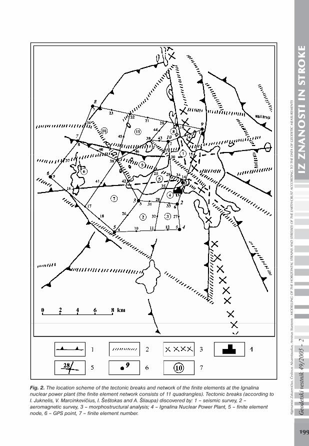
Fig. 2. The location scheme of the tectonic breaks and network of the finite elements at the Ignalinanuclear power plant (the finite element network consists of 11 quadrangles). Tectonic breaks (according toI. Juknelis, V. Marcinkevičius, I. Šeštokas and A. Šliaupa) discovered by: 1 – seismic survey, 2 –aeromagnetic survey, 3 – morphostructural analysis; 4 – Ignalina Nuclear Power Plant, 5 – finite elementnode, 6 – GPS point, 7 – finite element number.
Alg
iman
tas
Zak
arev
ičiu
s, Č
eslo
vas
Aks
amita
uska
s, A
rmin
as S
tani
onis
- M
OD
ELLI
NG
OF
THE
HO
RIZO
NTA
L ST
RAIN
S A
ND
STR
ESSE
S O
F TH
E EA
RTH
-CRU
ST A
CC
ORD
ING
TO
TH
E D
ATA
OF
GEO
DET
IC M
EASU
REM
ENTS
stevilka 2_05-beckup.pmd 18.6.2005, 21:56199

200
Geo
dets
ki v
estn
ik 4
9/20
05 –
2IZ
ZN
IZ Z
NIZ
ZN
IZ Z
NIZ
ZN
AN
OS
AN
OS
AN
OS
AN
OS
AN
OS
TI
IN S
TI
IN S
TI
IN S
TI
IN S
TI
IN S
TR
TR
TR
TR
TR
OK
EO
KE
OK
EO
KE
OK
E Measurement data were processed in the Geodesy Institute of the VGTU and the Danish company,,Nellemann & Bjornkjar” using the program packages GPPS and FILLNET.
It turned out that after processing of the results of measurements [18] the average quadraticerrors of measurement of the distances between points of the polygon (precision of measuredchords) were within the limits of 0,3 – 2,4 mm. The average quadratic errors of spatial coordinatesdid not exceed 1,2 mm. Changes of point coordinates within the period from September 1998 toSeptember 1999 are presented in the table 2.
Point number x (m) y (m) Point number x (m) y (m) 1 0,000 0,000 6 –0,006 0,008 2 0,013 0,004 7 0,003 0,002 3 0,008 0,009 8 –0,010 –0,002 4 0,010 0,000 9 0,004 0,001 5 0,013 0,004 10 0,005 0,000
Table 2. Changes of point coordinates.
The geodynamic polygon of the Ignalina Nuclear Power Plant was chosen to carry out the studies,because the tectonic structure is complicated in this territory, the crystal foundation is split intoblocks of different size, the main break systems – submeridian and latitude – have formed thenumber of subregional structures and also the Drűkđiai site of latitude direction [10, 20].
Very intensive anomalies of magnetic field are also distinguished in this region: the area ofDrűkđiai ÄT anomalies was fixed, in the background of which the range of round anomalieswith maximum value of 1350 nT is distinguished [20].
According to the methods of calculation presented, two plane (2-D) models of geometric bodywere made to model horizontal strains and stresses of the Earth-crust. The finite element methodwas applied with a presumption that the character of limited size finite element deformationschosen is isotropic. The first two-dimension model of geometric body is made from 16 finiteelements (quadrangles) (Fig. 1). The second model of geometric body is made from 11 finiteelements (quadrangles) (Fig. 2). The expansion of territory studied in finite elements, takinginto account the positions of initial points and conditions of expansion, was carried out usingthe program package Ansys [2].
Fig. 3. Geometrical scheme of the finite element.
Alg
iman
tas
Zak
arev
ičiu
s, Č
eslo
vas
Aks
amita
uska
s, A
rmin
as S
tani
onis
- M
OD
ELLI
NG
OF
THE
HO
RIZO
NTA
L ST
RAIN
S A
ND
STR
ESSE
S O
F TH
E EA
RTH
-CRU
ST A
CC
ORD
ING
TO
TH
E D
ATA
OF
GEO
DET
IC M
EASU
REM
ENTS
stevilka 2_05-beckup.pmd 18.6.2005, 21:57200

201
Geo
dets
ki v
estn
ik 4
9/20
05 –
2IZ
ZN
IZ Z
NIZ
ZN
IZ Z
NIZ
ZN
AN
OS
AN
OS
AN
OS
AN
OS
AN
OS
TI
IN S
TI
IN S
TI
IN S
TI
IN S
TI
IN S
TR
TR
TR
TR
TR
OK
EO
KE
OK
EO
KE
OK
EThe quadrangle is described by eight nodes: I, J, K, L, M, N, O and P. The geometry of the finiteelement, the distribution of nodes and the system of coordinates are presented in theFig. 3. Eachnode of the quadrangle has two degrees of freedom: movements in the directions of north and east.
Deformation of the finite element is described by formulae [2, 32]:
,tsutsutsutsu
tstsutstsu
tstsutstsuu
iiPiiOiiNiiM
iiiiLiiiiK
iiiiJiiiiIi
111111112
1
111111
1111114
1
2222
(22)
,tsvtsvtsvtsv
tstsvtstsv
tstsvtstsvv
iiPiiOiiNiiM
iiiiLiiiiK
iiiiJiiiiIi
111111112
1
111111
1111114
1
2222
(23)
here: Iu , , , , , , , , , , , , , , , Ju Ku Lu Mu Nu Ou Pu Iv Jv Kv Lv Mv Nv Ov Pv – shifts of node
coordinates, is , it – values of conditional coordinates of calculated points (the range from -1 to
+1 in the finite element) (Fig. 3).
The shift of nodes of the finite elements was calculated using Ansys code. When calculatingshifts of nodes, the obtained mechanical plane model of isotropic body deformations is estimatedaccording to the information of initial points.
It is impossible to determine absolute indices of the Earth-crust deformations from the beginningof deformation development according to the geodetic measuring; it is only possible to determinethe change increments of deformations within a certain period of time from initial to repeatedmeasurements. Therefore, basing oneself on geodetic measuring and functional dependency ofstrains and geodynamic stresses, it is possible to calculate changes of geodynamic stresses withinthe period of time between repeated measurements.
Relative linear and shear horizontal strains, changes of normal and shear stresses and changesof the principal stresses were estimated in the finite element nodes. Values of changes of horizontalstrains and geodynamic stresses are presented in tables 3 and 4. Directions of the principalstresses of the finite element are presented in Fig. 4 and 5. The principal stresses are perpendicularto each other.
Alg
iman
tas
Zak
arev
ičiu
s, Č
eslo
vas
Aks
amita
uska
s, A
rmin
as S
tani
onis
- M
OD
ELLI
NG
OF
THE
HO
RIZO
NTA
L ST
RAIN
S A
ND
STR
ESSE
S O
F TH
E EA
RTH
-CRU
ST A
CC
ORD
ING
TO
TH
E D
ATA
OF
GEO
DET
IC M
EASU
REM
ENTS
stevilka 2_05-beckup.pmd 18.6.2005, 21:57201

202
Geo
dets
ki v
estn
ik 4
9/20
05 –
2IZ
ZN
IZ Z
NIZ
ZN
IZ Z
NIZ
ZN
AN
OS
AN
OS
AN
OS
AN
OS
AN
OS
TI
IN S
TI
IN S
TI
IN S
TI
IN S
TI
IN S
TR
TR
TR
TR
TR
OK
EO
KE
OK
EO
KE
OK
E
Node
number 610xx
610yy 610zz610xy xx , MPa yy , MPa xy , MPa
1 , MPa 2 , MPa
1 0,563 0,006 -0,190 -2,520 0,042 0,011 -0,071 0,099 -0,046 2 -0,096 0,006 0,030 -0,866 -0,007 -0,001 -0,024 0,020 -0,029 3 -0,753 0,199 0,185 -1,105 -0,053 0,001 -0,031 0,015 -0,067 4 0,089 -1,940 0,617 0,306 -0,030 -0,143 0,009 -0,029 -0,144 5 -1,647 0,322 0,442 1,755 -0,117 -0,007 0,049 0,012 -0,136 6 0,869 -5,416 1,516 3,464 -0,036 -0,388 0,097 -0,011 -0,413 7 -3,143 -0,302 1,148 3,537 -0,240 -0,081 0,099 -0,034 -0,288 8 1,621 -1,686 0,022 2,812 0,090 -0,096 0,079 0,119 -0,125 9 -1,947 0,860 0,362 -6,257 -0,129 0,028 -0,175 0,141 -0,243
10 0,004 -0,453 0,150 -0,290 -0,008 -0,034 -0,008 -0,006 -0,036 12 0,284 -1,081 0,266 1,046 0,001 -0,075 0,029 0,011 -0,085 14 -0,350 -0,071 0,140 0,151 -0,027 -0,012 0,004 -0,011 -0,029 17 0,029 -0,648 0,206 0,068 -0,010 -0,048 0,002 -0,010 -0,048 20 0,091 -0,414 0,108 1,586 -0,001 -0,029 0,044 0,031 -0,062 22 -0,444 0,108 0,112 -0,620 -0,031 0,000 -0,017 0,008 -0,039 25 0,198 0,237 -0,145 0,878 0,019 0,021 0,025 0,045 -0,004 28 0,255 -0,047 -0,069 0,765 0,018 0,001 0,021 0,033 -0,013 31 0,175 0,108 -0,094 0,132 0,015 0,011 0,004 0,017 0,009 33 -0,496 1,101 -0,202 -0,437 -0,016 0,073 -0,012 0,075 -0,018 37 -0,027 -0,586 0,204 -0,581 -0,013 -0,044 -0,016 -0,006 -0,051 38 -0,095 -0,511 0,202 -0,186 -0,017 -0,040 -0,005 -0,016 -0,041 49 -0,301 -1,143 0,481 0,812 -0,044 -0,091 0,023 -0,035 -0,100 50 -1,354 -0,196 0,517 -0,610 -0,105 -0,040 -0,017 -0,036 -0,109 51 -0,054 0,424 -0,123 -2,580 0,004 0,031 -0,072 0,091 -0,056
Table 3. Horizontal deformations and changes of geodynamic stresses (results were obtained using thefinite element network consisting of 16 quadrangles).
Node number
610xx 610yy 610zz
610xy xx , MPa yy , MPa xy , MPa 1 , MPa 2 , MPa
1 0,143 -0,901 0,253 -0,911 -0,006 -0,065 -0,026 0,003 -0,074 2 0,026 -0,184 0,053 -0,114 -0,002 -0,013 -0,003 -0,001 -0,014 3 -0,432 0,010 0,141 -0,441 -0,032 -0,007 -0,012 -0,002 -0,037 4 0,397 -1,824 0,476 0,774 -0,004 -0,129 0,022 -0,001 -0,132 5 -2,589 -0,225 0,938 4,372 -0,197 -0,065 0,122 0,008 -0,270 6 0,293 -0,845 0,184 1,098 0,006 -0,058 0,031 0,019 -0,070 7 0,364 -4,263 1,300 3,033 -0,052 -0,312 0,085 -0,027 -0,337 8 0,540 -0,070 -0,157 -1,645 0,039 0,005 -0,046 0,071 -0,027 9 -1,439 0,168 0,424 1,438 -0,104 -0,014 0,040 0,001 -0,120
11 -0,145 0,207 -0,021 0,419 -0,007 0,013 0,012 0,018 -0,012 14 0,237 -0,353 0,039 -1,484 0,011 -0,022 -0,042 0,039 -0,050 17 -0,090 -0,070 0,053 0,482 -0,008 -0,007 0,014 0,006 -0,021 20 0,093 0,304 -0,133 0,183 0,013 0,024 0,005 0,026 0,011 22 -0,405 0,883 -0,159 -0,047 -0,014 0,058 -0,001 0,058 -0,014 28 -0,930 -0,135 0,355 1,191 -0,072 -0,027 0,033 -0,010 -0,090 29 0,012 -1,037 0,341 -0,595 -0,018 -0,077 -0,017 -0,014 -0,082 38 -0,042 -0,859 0,300 0,303 -0,019 -0,065 0,008 -0,018 -0,066 39 -0,554 -0,099 0,218 -0,205 -0,043 -0,018 -0,006 -0,016 -0,044
Table 4. Horizontal deformations and changes of geodynamic stresses (results were obtained using thefinite element network consisting of 11 quadrangles).Alg
iman
tas
Zak
arev
ičiu
s, Č
eslo
vas
Aks
amita
uska
s, A
rmin
as S
tani
onis
- M
OD
ELLI
NG
OF
THE
HO
RIZO
NTA
L ST
RAIN
S A
ND
STR
ESSE
S O
F TH
E EA
RTH
-CRU
ST A
CC
ORD
ING
TO
TH
E D
ATA
OF
GEO
DET
IC M
EASU
REM
ENTS
stevilka 2_05-beckup.pmd 18.6.2005, 21:57202
203
Geo
dets
ki v
estn
ik 4
9/20
05 –
2IZ
ZN
IZ Z
NIZ
ZN
IZ Z
NIZ
ZN
AN
OS
AN
OS
AN
OS
AN
OS
AN
OS
TI
IN S
TI
IN S
TI
IN S
TI
IN S
TI
IN S
TR
TR
TR
TR
TR
OK
EO
KE
OK
EO
KE
OK
E
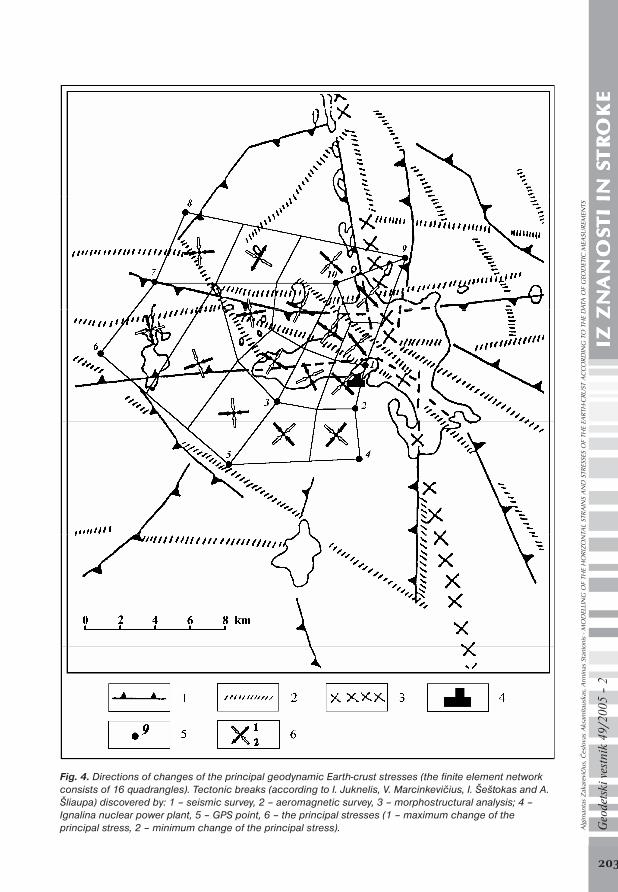
Fig. 4. Directions of changes of the principal geodynamic Earth-crust stresses (the finite element networkconsists of 16 quadrangles). Tectonic breaks (according to I. Juknelis, V. Marcinkevičius, I. Šeštokas and A.Šliaupa) discovered by: 1 – seismic survey, 2 – aeromagnetic survey, 3 – morphostructural analysis; 4 –Ignalina nuclear power plant, 5 – GPS point, 6 – the principal stresses (1 – maximum change of theprincipal stress, 2 – minimum change of the principal stress).
Alg
iman
tas
Zak
arev
ičiu
s, Č
eslo
vas
Aks
amita
uska
s, A
rmin
as S
tani
onis
- M
OD
ELLI
NG
OF
THE
HO
RIZO
NTA
L ST
RAIN
S A
ND
STR
ESSE
S O
F TH
E EA
RTH
-CRU
ST A
CC
ORD
ING
TO
TH
E D
ATA
OF
GEO
DET
IC M
EASU
REM
ENTS
stevilka 2_05-beckup.pmd 18.6.2005, 21:57203
204
Geo
dets
ki v
estn
ik 4
9/20
05 –
2IZ
ZN
IZ Z
NIZ
ZN
IZ Z
NIZ
ZN
AN
OS
AN
OS
AN
OS
AN
OS
AN
OS
TI
IN S
TI
IN S
TI
IN S
TI
IN S
TI
IN S
TR
TR
TR
TR
TR
OK
EO
KE
OK
EO
KE
OK
E
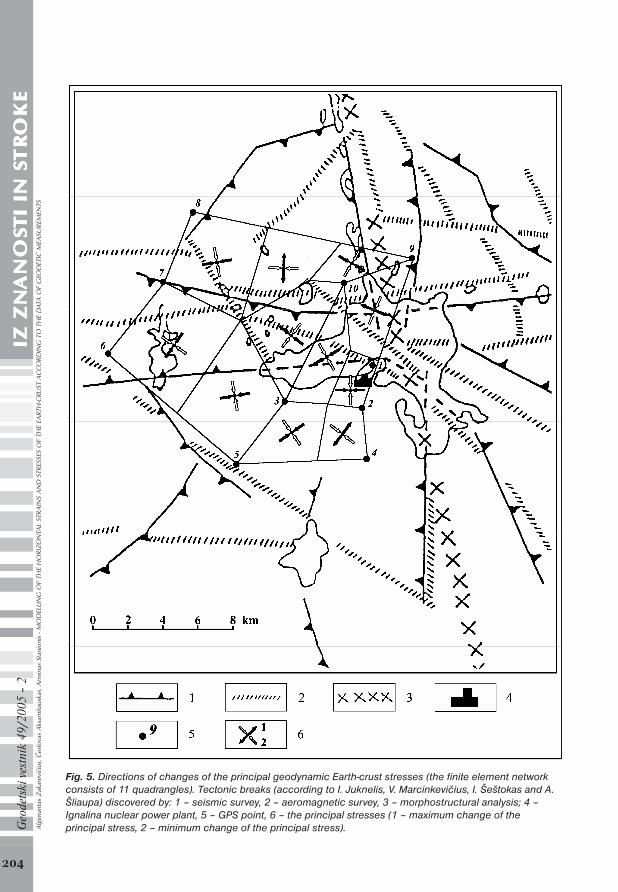
Fig. 5. Directions of changes of the principal geodynamic Earth-crust stresses (the finite element networkconsists of 11 quadrangles). Tectonic breaks (according to I. Juknelis, V. Marcinkevičius, I. Šeštokas and A.Šliaupa) discovered by: 1 – seismic survey, 2 – aeromagnetic survey, 3 – morphostructural analysis; 4 –Ignalina nuclear power plant, 5 – GPS point, 6 – the principal stresses (1 – maximum change of theprincipal stress, 2 – minimum change of the principal stress).Alg
iman
tas
Zak
arev
ičiu
s, Č
eslo
vas
Aks
amita
uska
s, A
rmin
as S
tani
onis
- M
OD
ELLI
NG
OF
THE
HO
RIZO
NTA
L ST
RAIN
S A
ND
STR
ESSE
S O
F TH
E EA
RTH
-CRU
ST A
CC
ORD
ING
TO
TH
E D
ATA
OF
GEO
DET
IC M
EASU
REM
ENTS
stevilka 2_05-beckup.pmd 18.6.2005, 21:57204
205
Geo
dets
ki v
estn
ik 4
9/20
05 –
2IZ
ZN
IZ Z
NIZ
ZN
IZ Z
NIZ
ZN
AN
OS
AN
OS
AN
OS
AN
OS
AN
OS
TI
IN S
TI
IN S
TI
IN S
TI
IN S
TI
IN S
TR
TR
TR
TR
TR
OK
EO
KE
OK
EO
KE
OK
EWhen using the results of modelling analysis (Fig. 4 and 5), some laws of distribution of changesof the principal stresses of the Earth-crust that are related with the tectonic structure of theterritory [10] and geophysical fields [12] are noticed in the Ignalina Nuclear Power Plant region.Changes of maximum stresses are almost parallel, and changes of minimum stresses areperpendicular to breaks of the crystal foundation.
The results of horizontal strains and geodynamic stresses of the Earth-crust in the IgnalinaNuclear Power Plant region established in modelling by the finite element method do notcontradict [28, 31] the results obtained from studies.
5 CONCLUSIONS
1. The modelling of horizontal strains and geodynamic stresses of the Earth-crust according tothe data of geodetic measurements, computed with the finite element method, details the structureof current tectonic activity in the research territory and facilitates the geotectonic interpretationof measurement results.
2. By applying the program package Ansys to model strains and stresses of the Earth-crust bythe finite element method, the mechanical model of isotropic body deformations is estimated.The model of horizontal strains and stresses of the Earth-crust made in this way correspondsbetter to the actual physical process occurring in the Earth-crust than models made on thebasis of rectilinear geometrical interpolation.
3. The tensor analysis methods that are invariant with respect to the system of coordinates maybe applied in determining relation between horizontal strains of the Earth-crust and geodynamicstresses and laws of their change. Having expressed stresses in strains according to the Hooke’slaw, new data – changes of geodynamic stresses were obtained.
4. Using the methods of estimation the plane stresses suggested, it is possible to determinegeodynamic laws of current tectonic and local movements occurring in the Earth-crust. Thechange of the geodynamic Earth-crust stresses was estimated and the changes of stress be-tween repeated measurements were determined in the Ignalina Nuclear Power Plant region.It is obvious from the results obtained that the significant change of geodynamic stressesoccurs in the territory.
5. The model of the horizontal Earth-crust movements made by the finite element method inthe Ignalina Nuclear Power Plant region has clear connections with the tectonic structure ofthe Earth-crust. The orientation of change directions of the principal maximum stresses isclose to the directions of the main breaks of the Earth-crust in this territory and changesfrom –0,036 MPa to 0,141 MPa, and the orientation of change directions of minimum stressesis perpendicular to the tectonic breaks and changes from -0,413 MPa to 0,011 MPa. Theprevailing direction of geotectonic pressure of the Earth-crust in this region is perpendicularto the break zone crossing the Lake Drűkđiai that goes from west to east and makes a turn tosoutheast in the eastern part of the Lake Drűkđiai.
Alg
iman
tas
Zak
arev
ičiu
s, Č
eslo
vas
Aks
amita
uska
s, A
rmin
as S
tani
onis
- M
OD
ELLI
NG
OF
THE
HO
RIZO
NTA
L ST
RAIN
S A
ND
STR
ESSE
S O
F TH
E EA
RTH
-CRU
ST A
CC
ORD
ING
TO
TH
E D
ATA
OF
GEO
DET
IC M
EASU
REM
ENTS
stevilka 2_05-beckup.pmd 18.6.2005, 21:57205
206
Geo
dets
ki v
estn
ik 4
9/20
05 –
2IZ
ZN
IZ Z
NIZ
ZN
IZ Z
NIZ
ZN
AN
OS
AN
OS
AN
OS
AN
OS
AN
OS
TI
IN S
TI
IN S
TI
IN S
TI
IN S
TI
IN S
TR
TR
TR
TR
TR
OK
EO
KE
OK
EO
KE
OK
E References1. Angevine, Ch. L.; Heller, P. L.; Paola, Ch. Quantitative sedimentary basin modelling. A.A.P.G. continuing education
course note, Series 32, Tulsa. 133 p.
2. Ansys Theory Reference. Tenth Edition. SAS IP, Inc., 1998.
3. Atkočiűnas, J.; Nagevičius, J. Foundations of the theory of elasticity (Tamprumo teorijos pagrindai). Vilnius: Technika,2000. 264 p. (in Lithuanian).
4. Calais, E.; Galisson, L.; Stéphan, J.-F.; Delteil, J.; Deverchčre, J.; Larroque, C.; Mercier de Lépinay, B.; Popoff, M.;Sosson, M. Crustal strain in the Southern Alps, France, 1948–1998. Tectonophysics, Vol 319, Issue 1. Elsevier ScienceB. V., 2000, p. 1–17.
5. Čyras, A.; Borkowski, A.; Karkauskas, R. Theory and methods of optimization of rigid-plastic systems. Vilnius:Technika, 2004. 354 p.
6. Ferhat, G.; Feigl, K. L.; Ritz, J.-F.; Souriau, A. Geodetic measurement of tectonic deformation in the southern Alpsand Provence, France, 1947–1994. Earth and Planetary Science Letters, Vol 159, Issues 1-2. Elsevier Science B. V.,1998, p. 35–46.
7. Jaeger, J. C. Elasticity, fracture and flow: with engineering and geological applications. 3rd ed. London: Methuen, 1969. 268 p.
8. Kahle, H.-G.; Müller, M. V.; Geiger, A.; Danuser, G.; Mueller, S.; Veis, G.; Billiris, H.; Paradissis, D. The strain field innorthwestern Greece and the Ionian Islands: results inferred from GPS measurements. Tectonophysics, Vol 249,Issues 1–2. Elsevier Science B. V., 1995, p. 41–52.
9. Lesne, O.; Calais, E.; Deverchčre, J. Finite element modelling of crustal deformation in the Baikal rift zone: newinsights into the active–passive rifting debate. Tectonophysics, Vol 289, Issue 4. Elsevier Science B. V., 1998, p. 327–340.
10. Marcinkevičius, V.; Lađkovas, J. Tectonic conditions of Ignalina Nuclear Power Plant region (Ignalinos atominëselektrinës rajono tektoninës sŕlygos). Geological horizons (Geologijos akiračiai), No 1–2. Vilnius, 1996, p. 8–23 (inLithuanian).
11. McKenzie, D.; Jackson, J. The relationship between strain rates, crustal thickening, palaeomagnetism, finite strainand fault movements within a deforming zone. Earth and Planetary Science Letters, Vol 65, Issue 1. Elsevier ScienceB. V., 1983, p. 182–202.
12. Petroškevičius, P. Gravitation field effect on geodetic observations (Gravitacijos lauko poveikis geodeziniamsmatavimams). Vilnius: Technika, 2004. 292 p. (in Lithuanian).
13. Puglisi, G.; Bonforte, A.; Maugeri, S. R. Ground deformation patterns on Mount Etna, 1992 to 1994, inferred fromGPS data. Bulletin of Volcanology, Vol 62, Numbers 6-7. Springer–Verlag Heidelberg, 2001, p. 371–384.
14. Ruiz, A. M.; Ferhat, G.; Alfaro, P.; Sanz de Galdeano, C.; de Lacy, M. C.; Rodríguez-Caderot, G.; Gil, A. J. Geodeticmeasurements of crustal deformation on NW–SE faults of the Betic Cordillera, southern Spain, 1999–2001. Journalof Geodynamics, Vol 35, Issue 3. Pergamon-Elsevier science Ltd, 2003, p. 259–272.
15. Sagiya, T.; Miyazaky, S.; Tada, T. Continuous GPS array and present-day crustal deformation of Japan. Pure andApplied Geophysics, Vol 157, Numbers 11-12. Birkhäuser Verlag AG, 2000, p. 2303–2322.
16. Shanlong Kuang. Geodetic network analysis and optimal design: concepts and applications. Ann Arbor Press, Inc.Chelsea, Michigan, 1996. 368 p.
17. Singiresu S. Rao. The finite element method in engineering. Third edition. Butterworth–Heinemann, 1999. 556 p.
18. Skeivalas, J. Treatment of correlated geodetic measurements (Koreliuotř geodeziniř matavimř rezultatř matematinisapdorojimas). Vilnius: Technika, 1995. 272 p. (in Lithuanian).
19. Sue, C.; Martinod, J.; Tricart, P.; Thouvenot, F.; Gamond, J-F.; Fréchet, J.; Marinier, D.; Glot, J-P.; Grasso, J-R. Activedeformation in the inner western Alps inferred from comparison between 1972-classical and 1996-GPS geodeticsurveys. Tectonophysics, Vol 320, Issue 1. Elsevier Science B. V., 2000, p. 17–29.
20. Tectonic structure of Lithuania (Lietuvos tektoninë sandara). Compiled and edited by P. Suveizdis, Institute ofGeology and Geography, Vilnius, 2003. 160 p. (in Lithuanian).
21. Vaníček, P.; Craymer, M. R.; Krakiwsky, E. J. Robustness analysis of geodetic horizontal networks. Journal of Geodesy,Vol 75, No 4. Springer–Verlag, 2001, p. 199–209.A
lgim
anta
s Z
akar
evič
ius,
Čes
lova
s A
ksam
itaus
kas,
Arm
inas
Sta
nion
is -
MO
DEL
LIN
G O
F TH
E H
ORI
ZON
TAL
STRA
INS
AN
D S
TRES
SES
OF
THE
EART
H-C
RUST
AC
CO
RDIN
G T
O T
HE
DAT
A O
F G
EOD
ETIC
MEA
SURE
MEN
TS
stevilka 2_05-beckup.pmd 18.6.2005, 21:57206
207
Geo
dets
ki v
estn
ik 4
9/20
05 –
2IZ
ZN
IZ Z
NIZ
ZN
IZ Z
NIZ
ZN
AN
OS
AN
OS
AN
OS
AN
OS
AN
OS
TI
IN S
TI
IN S
TI
IN S
TI
IN S
TI
IN S
TR
TR
TR
TR
TR
OK
EO
KE
OK
EO
KE
OK
E22. Vaníček, P.; Krakiwsky, E. J. Geodesy: The concepts. 2nd rev. ed. North–Holland, Amsterdam, 1986. 697 p.
23. Varadan, T. K.; Bhaskar, K. Analysis of Plates: theory and problems. Narosa Publishing House, 1999. 190 p.
24. Vigny, C.; Chéry, J.; Duquesnoy, T.; Jouanne, F.; Ammann, J.; Anzidei, M.; Avouac, J.-P.; Barlier, F.; Bayer, R.; Briole,P.; Calais, E.; Cotton, F.; Duquenne, F.; Feigl, K. L.; Ferhat, G.; Flouzat, M.; Gamond, J.-F.; Geiger, A.; Harmel, A.;Kasser, M.; Laplanche, M.; Le Pape, M.; Martinod, J.; Ménard, G.; Meyer, B.; Ruegg, J.-C.; Scheubel, J.-M.; Scotti, O.;Vidal, G. GPS network monitors the Western Alps’ deformation over a five-year period: 1993–1998. Journal ofGeodesy, Vol 76, Issue 2. Springer–Verlag Heidelberg, 2002, p. 63–76.
25. Zadro, M.; Braitenberg, C. Measurements and interpretations of tilt-strain gauges in seismically active areas. Earth-Science Reviews, Vol 47, Issues 3–4. Elsevier Science B. V., 1999, p. 151–187.
26. Zakarevičius, A. Analysis of deformations of zero order GPS network (Nulinës klasës GPS tinklo deformacijř analizë).Geodesy and Cartography (Geodezija ir kartografija), No 1(23), Vilnius: Technika, 1996, p. 53–61 (in Lithuanian).
27. Zakarevičius, A. Investigation of the recent geodynamic processes in the territory of Lithuania (Dabartiniřgeodinaminiř procesř Lietuvos teritorijoje tyrimas). Vilnius: Technika, 2003. 195 p. (in Lithuanian).
28. Zakarevičius, A.; Aksamitauskas, Č.; Stanionis, A. Horizontal deformations of the Earth’s crust in Ignalina nuclearpower plant region (
). I i , 49, Ï , 2003, p. 102–110 (inRussian).
29. Zakarevičius, A.; Stanionis, A. Modelling the horizontal movements and deformations of the earth crust by the
finite element method (Horizontali j Žem s plutos poslinki ir deformacij modeliavimas baigtini eelement metodu) . Geodesy and Cartography (Geodezija ir kartografija), Vol XXX, No 2, Vilnius: Technika, 2004,p. 35–40 (in Lithuanian).
30. Zakarevičius, A.; Stanionis, A. The dispersion structure of horizontal deformations of Lithuanian geodetic networks(Lietuvos geodezini tinkl horizontali j deformacij sklaidos strukt ra). Geodesy and Cartography(Geodezija ir kartografija), Vol XXVIII, No 4, Vilnius: Technika, 2002, p. 117–124 (in Lithuanian).
31. Zakarevičius, A.; Stanionis, A. The features of dispersion of horizontal deformations of the Earth’s crust in theregion of Ignalina nuclear power plant (Horizontali j Žem s plutos deformacij Ignalinos atomin s e
elektrin s rajone sklaidos ypatumai) . Geodesy and Cartography (Geodezija ir kartografija), Vol XXIX, No 4,Vilnius: Technika, 2003, p. 119–123 (in Lithuanian).
32. Zienkiewicz, O. C.; Taylor, R. L. The finite element method. Volume 1, Fifth edition. Butterworth-Heinemann, 2000.689 p.
33. , . . : , 1979. 182 . (in Russian).
Algimantas Zakarevičius, Česlovas Aksamitauskas, Arminas StanionisDepartment of Geodesy and Cadastre, Faculty of Environmental Engineering,Vilnius Gediminas Technical University, Sauletekio al. 11, LT-10223 Vilnius-40, Lithuania,E-pošta: [email protected]
Prispelo za objavo: 29. november 2004Sprejeto: 14. maj 2005 A
lgim
anta
s Z
akar
evič
ius,
Čes
lova
s A
ksam
itaus
kas,
Arm
inas
Sta
nion
is -
MO
DEL
LIN
G O
F TH
E H
ORI
ZON
TAL
STRA
INS
AN
D S
TRES
SES
OF
THE
EART
H-C
RUST
AC
CO
RDIN
G T
O T
HE
DAT
A O
F G
EOD
ETIC
MEA
SURE
MEN
TS
stevilka 2_05-beckup.pmd 18.6.2005, 21:57207