modelling of the stresses and strains distribution in an ... · pdf filethe plate's...
TRANSCRIPT

Electronic Journal of Structural Engineering, 9 (2009)
37
1 INTRODUCTION
The determination of the pavement thicknesses was based purely on the experiment until the 1920 years. These experiments were developed also with the time. The rigid RCC pavements, like those of con-ventional concretes, can be analysed by the plate's theory. The plate's theory supposes that the concrete slab is a medium thickness plate with plane sections before and after strains. If the wheel is placed close to the edge of the slab, then only the plate's theory can be used for the rigid pavements. The plate's the-ory or the layers theory can be used when the load is applied to the slab centre. The existence of the joints in the rigid pavements makes the use of layers theory inapplicable (Jeuffroy and Sauterey, 1989).
The design methods were developed by various organisms for the determination of the necessary thicknesses of pavements (Gauthier et al., 2004). The analytical solutions, developed thereafter, vary from the "Closed-form Formulas" to the complex derivations which are valid for the determination of the stress and the strains in the rigid pavements. But with the development of the powerful finite element method, we notice a significant evolution in the analysis of the rigid pavements. Various finite ele-ment models have been developed for analysing the behaviour of concrete pavement systems. For these
analysis, computer programs were developed by us-ing the finite element method such as ILLI-SLAB (Tabatabaie and Barenberg 1980), WESLIQID (Chou 1981), J-SLAB (Tayabji and Colley 1986), FEACONS-IV (Choubane and Tia 1995), IS-LAB2000 (Khazanovich et al. 2000) and WESLAYER (Huang, 2004). The main advantage of these approaches is the evaluation of the critical load transfer phenomena and the stress distributions in the rigid pavements like the RCC slabs. Moreover, Channakeshava et al. (1993), Masad et al. (1996) and William and Shoukry (2001) employed the finite element methods in order to analyze the behaviour of concrete pavements. Using Abaqus software, Zaghloul et al. (1994), Uddin et al. (1997) and Darter et al. (2001) developed models for the study of rigid pavements and its foundation. Davids et al. (2003) studied, also, the effect of dowel looseness on the structural response of jointed concrete pave-ments. The study employed 3D finite element mod-els developed with EverFE.
In the present study, a numerical 3D modelling was used by introducing, to the computer code "Abaqus", the behaviour law of the RCC. Other methods of 2D modelling were applied for the de-termination of the stress and the strains in the RCC slab such as the Closed-form Formulas and the Port-land Cement Association (PCA) method. Finally, the
Modelling of the Stresses and Strains Distribution in an RCC Pavement Using the Computer Code "Abaqus"
M. Zdiri* Civil Engineering Laboratory, National Engineering School of Tunis, BP 37, Tunis-Belvédère 1002, Tunisia.
Laboratoire Génie Civil et Environnemental - Ecole des Mines de Douai, rue Charles Boursel -59508 France
N. Abriak Laboratoire Génie Civil et Environnemental - Ecole des Mines de Douai, rue Charles Boursel -59508 France
J. Neji Applied Mechanics and Systems Research Laboratory - Polytechnic School of Tunis, Tunisia.
M. Ben Ouezdou Civil Engineering Laboratory, National Engineering School of Tunis, BP 37, Tunis-Belvédère 1002, Tunisia.
*Email: [email protected]
ABSTRACT: The Roller Compacted Concrete (RCC) pavements are built employing the Portland cement. The design of the rigid RCC pavements was developed gradually through methods of design. These methods were established by various organisms for the determination of the necessary thicknesses of roadways. In this study a numerical 3D modelling was used by introducing to the computer code "Abaqus" the behaviour law of the RCC. Several other methods of 2D modelling were applied for the determination of the stress and the strains in the RCC slab such as the Closed-form Formulas and the Portland Cement Association (PCA) method. Finally the results of 3D modelling are compared with those obtained by the various other methods. The comparison shows good correspondences although the 3D modelling gives results slightly lower than those given by the 2D methods in stresses.

Electronic Journal of Structural Engineering, 9 (2009)
38
results of 3D modelling were compared with those obtained by the various other methods.
2 NUMERICAL MODELING 3D BY THE COMPUTER CODE "ABAQUS 6.7"
2.1 The 3D modelling principle
In the present model, a solid foundation was used, which is more realistic although this modelling re-quires much more memory for the resolution. The solid foundation is more realistic than the liquid foundation, because the deflection in any nodal point depends not only on the force in this node but also of the forces in all the other nodes. Moreover, all the analytical solutions of the 2D models are based on the proposal that the slab and the foundation are in perfect contact (Coquand, 1989). With the advan-tages of calculations of the numerical methods by computers, the developed analyses are based on a partial contact between the layers (Huang, 2004). This work includes, mainly, a 3D modelling by the use of the computer code of the finite elements "Abaqus 6.7" in order to understand, with more pre-cision, the distribution and the evolution of the stresses and displacements in the entire RCC slab. These results were shown especially for many load-ing position, in top and bottom fibres and in the in-terface with the sub-base. In the numerical 3D mod-elling by finite elements using Abaqus 6.7, the authors choose various options of manual and auto-matic incrementing with an automatic tolerance of convergence. The control parameters of the man-agement of the numerical analysis of the problem are adjusted automatically with a low manual adjust-ment. The convergence criteria are also adjusted dur-ing the analysis to ensure a precise solution.
In this numerical approach, two RCC slab sepa-rated by a joint, were modelled. Both rest on a gravel sub-base suitably compacted. The whole also rests on a ground support. The geometries and the me-chanical properties of material were introduced. These introduced parameters were: the elastic modulus E, the Poisson's ratio ν and the admissible stresses of tensile and compression. All dimensions are finite in 3D; the diagrams of the model are pre-sented in Figures 1 and 2. The data of the adopted model are the following:
-Two RCC slabs of (4.00 m ×7.00 m), h= 20 cm,
E = 31000 MPa, ν=0.22
- Gravel foundation layer of (4.00 m × 14.00 m),
hf= 30 cm, Ef = 155 MPa, νf=0.35
- Ground layer of (4.00 m × 14.00 m): hs= 130 cm,
Es = 50 MPa, νs=0.45
Figure 1. Model adopted for the RCC - plan view
Transverse section S-S
b) Elevation view
Figure 2 (a & b). Model adopted for the RCC
Basing on the literature, the Friction ratio Slab/Foundation was taken equal to 1.5 and the Fric-tion ratio Foundation/ground equal to 1.1. The dif-ference between the top and bottom RCC slab tem-peratures was assumed to be equal to 11°C (ARA, Inc., ERES Division, 2003).
2.2 Meshing and boundary conditions
The boundary conditions were selected in order to approach to the real boundary conditions. The gravel sub-base and ground support layers were fixed in the two directions 1 and 2. The two RCC slabs were fixed on one face in directions 1 and 2. The gravel sub-base and the two slabs were free in direction 3 and they can move in this direction. Only, the ground support was fixed in the direction 3 (Figure 1 and 2). Meshes based on hexahedrons with eight nodes were chosen. The size of the meshes was also optimized in order to obtain a compromise between the time and the stability of calculation (Figure 4). It
Gravel Foundation Layer
RCC Slab1
3
2
o
Support Ground Layer
Tire
4m
1
3
o
2 cm Joint
RCC Slab 1 RCC Slab 2
Contact surface of
loading
7m 7m
Circulation direction
4 m
S
S
2 cm Joint Circulation direction
RCC Slab1 (H,E,νννν)
1 2
o
Gravel Foundation Layer (hf, Ef,ννννf)
Tire loading
Support Ground Layer (hs, Es,ννννs)
RCC Slab2 (h,E,νννν) h
hf
hS

Electronic Journal of Structural Engineering, 9 (2009)
39
was found that a fine mesh (10 by 10 cm) is required in the RCC slab supporting the load. However a rela-tively coarse mesh (30 by 30 cm) was chosen in the gravel sub-base, ground support and RCC slab not supporting the load. It did not significantly affect the precision of the stress and displacement prediction.
Moreover, all the preceding analytical solutions of the 2D models are based on the proposal that the slab and the foundation are in perfect contact. In the present study, two assumptions can be considered in this modelling. The first consists in supposing that the interaction between the layers is without friction, which means that the layers are stuck. The second consists in considering a friction ratio between the RCC slab and the gravel foundation. Another fric-tion ratio was taken between the sub-base and the support ground.
Figure 3. Contact graph and surfaces interactions.
2.3 Various cases of loadings
Three cases of loading of the RCC slab were studied; an interior loading (load in the centre), a load in the corner and a load at the edge of the slab; but the ap-plied load were a static loading. The applied load was of 65000 N/tire which is equal to 740000 Pa. The three cases of loading are schematized in Figure 4: a) Interior loading (Load in the centre of the slab)
b) Load in the edge of the slab
c) Load in the corner of the slab
d) 3D Model for interior loading case Figure 4 (a, b, c & d). Different positions of load applied to the 3D Model
In their studies, ARA and ERES (ARA, Inc.,
ERES Division, 2003) indicated that load transfer ef-ficiency (LTE) at the transverse joints has only a limited effect on the distribution of the RCC bottom surface stresses. For this reason, this phenomena was not taken into accompt in the present modelling.
To assure adequate simulation of the tire–pavement
contact area, tire footprints were modelled using rec-
tangular shapes with equivalent contact areas as
showed in Figure 5. a) Real contact surface of tire b) Equivalent contact surface
Figure 5 (a & b). The adopted contact surface of tire.
2.4 The RCC behaviour
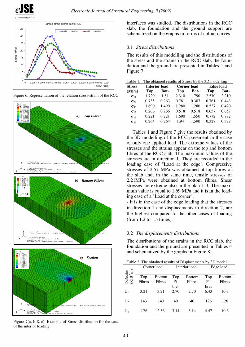
To suitably simulate the behaviour of the RCC be-fore and after cracking (rupture), the option "Con-crete Smeared Cracking" was used by introducing the necessary parameters to the definition of the be-haviour law of the RCC (Figure 6)
3 MODELLING RESULTS
In order to exploit suitably and to develop results of the 3D modelling using the computer code by finite elements "Abaqus 6.7", the distribution of the stress and displacements in the loading position and in the
0.3 Lc
0.6
Lc
Lc
0.6
Lc=
25
cm
0.871 Lc=35cm
Area=0.5227 Lc2
Slave
Surface Master
Surface
RCC slab
Contact Surface
of loading
7m
Circulation direction
4 m
RCC slab
Contact Surface
of loading
7m
Circulation direction
4 m
RCC slab
Contact Surface
of loading
7m
Circulation direction 4 m
Electronic Journal of Structural Engineering, 9 (2009)
40
0
5
10
15
20
25
30
35
0 0,0004 0,0008 0,0012 0,0016 0,002 0,0024 0,0028 0,0032 0,0036 0,004
Str
ess (M
Pa)
strain (m/m)
Stress-strain curves of the RCC
M1 M2 M3 M4
Figure 6. Representation of the relation stress-strain of the RCC
as presented in Figure 7 and 8.
Figure 7(a, b & c). Example of Stress distribution for the case of the interior loading.
interfaces was studied. The distributions in the RCC slab, the foundation and the ground support are schematized on the graphs in forms of colour curves.
3.1 Stress distributions
The results of this modelling and the distributions of the stress and the strains in the RCC slab, the foun-dation and the ground are presented in Tables 1 and Figure 7
Table 1. The obtained results of Stress by the 3D modelling
Interior load Corner load Edge load Stress
(MPa) Top Bot- Top Bot- Top Bot-
σ11 1.720 1.51 2.310 1.790 2.570 2.210
σ22 0.735 0.263 0.781 0.387 0.761 0.443
σ33 1.690 1.490 1.280 1.280 0.537 0.420
σ12 0.266 0.266 0.518 0.518 0.657 0.657
σ13 0.221 0.221 1.690 1.550 0.772 0.772
σ23 0.264 0.264 1.94 1.590 0.328 0.328
Tables 1 and Figure 7 give the results obtained by
the 3D modelling of the RCC pavement in the case of only one applied load. The extreme values of the stresses and the strains appear on the top and bottom fibres of the RCC slab. The maximum values of the stresses are in direction 1. They are recorded in the loading case of "Load at the edge". Compressive stresses of 2.57 MPa was obtained at top fibres of the slab and, in the same time, tensile stresses of 2.21MPa were obtained at bottom fibres. Shear stresses are extreme also in the plan 1-3. The maxi-mum value is equal to 1.69 MPa and it is in the load-ing case of a "Load at the corner".
- It is in the case of the edge loading that the stresses
in direction 1 and displacements in direction 2, are
the highest compared to the other cases of loading
(from 1.2 to 1.5 times).
3.2 The displacements distributions
The distributions of the strains in the RCC slab, the foundation and the ground are presented in Tables 4 and schematized by the graphs in Figure 8. Table 2. The obtained results of Displacements by 3D model
Corner load
Interior load Edge load
Def
lect
ion
(×1
0-5
m)
Top
Fibres
Bottom
Fibres
Top
Fi-
bres
Bottom
Fibres
Top
Fi-
bres
Bottom
Fibres
U1 3.21
3.21
2.70 2.70
6.43 10.3
U2 143
143
40 40
126 126
U3 1.76
2.36
3.14
3.14
4.47
10.6
b) Bottom Fibres
a) Top Fibres
c) Section c) Section

Electronic Journal of Structural Engineering, 9 (2009)
41
Figure 8(a, b & c). Displacements distribution for the three cases of the loading
In all loading cases, displacements in direction 2
are higher compared to those in direction 1 and 3. In this direction 2, deflections in the loading case at the corner (1.43×10
-3 m) are higher than those in the
other loading cases (0.40×10⁻³
m in the interior and 1.26×10
-3 m in the edge). Generally, in directions 2
and 3, the displacements, in the case of Edge load-ing, are higher than those in the other cases of load-ing.
4 APPLICATION OF THE 2D MODELLING TO THE RCC PAVEMENT
In 2D modelling several formulas, used for the study of the stresses and the strains in the rigid pavements, were applied such as the Closed-form Formulas and the PCA method.
4.1 Corner loading
For the loading in the corner, the Westergaard equa-tion which proposes a successive approximation method was used. It gives the stress σ and the de-flection ∆ on the bottom surface of the slab in the form 1 and 2 (Huang, 2004):
−=
6.0
2
2a1
h
P3
lσ (1)
−=
ll
2a88.01.1
k
P2
∆ (2)
Where l is the radius of relative stiffness (m), a is the contact radius (m), P is the concentrated loading (N), h is the thickness of the RCC slab (m) and k is the reaction modulus of the foundation (MPa/m). l can be determined by the formula:
25.0
2
3
k)1(12
Eh
−=
νl (3)
Where E: elastic modulus, ν: Poisson's ratio. For the studied cases, P= 65000 N, h= 0.20 m and
three cases of foundation were treated: k=35, k=95 and k= 250 MPa/m. Table 3 summarizes the results for these three treated cases.
The formulas 4 and 5, suggested by Ioannides et al. in 1985, were also used. In these equations, the finite element method was applied to evaluate the solution of Westergaard (Huang, 2004). The results are summarized in Table 3:
−=
72.0
2
c1
h
P3
lσ (4)
−=
ll
c69.0205.1
k
P2
∆ (5)
Where c can be taken: c=1.77×a
4.2 Interior Loading
For the interior loading case, the method suggested by Westergaard in 1926 was adopted to determine the stress and the deflection in rigid slab under circu-lar load of radius which is represented by the formu-
b) Interior
a) Corner
c) In edge

Electronic Journal of Structural Engineering, 9 (2009)
42
las 6 and 7 (Huang, 2004). The results are summa-rized in Table 4:
)6159.0b
Ln(h2
P)1(32
++
=l
π
νσ (6)
−
+=
2
2
a673.0
2
aLn
2
11
k8
P
lll π∆ (7)
Table 3. Results of the stresses and deflections for the corner loading case by two methods
EFoundation (MPa) 35 155 500
CBR 6 32 90
ERCC (MPa) 31000 31000 31000
k (MPa/m) 35 95 250
l (m) 0.91 0.71 0.53
σ Westergaard (MPa) 3.14 2.81 2.46
σ Ioannides (MPa) 3.22 2.83 2.404
∆ Westergaard (mm) 2.216 1.595 0.625
∆ Ioannides (mm) 2.281 1.627 0.718
Moreover the procedure of design "Design of air-
port concrete pavement" established by the Portland Cement Association (PCA) was applied. It leads to determine, according to the thickness of the RCC pavement, the tensile stress in bottom fibre of the pavement in the slab centre which is caused by the load of a given axle (PCA, 1984), (Gauthier et al., 2004). The calculation of the stress was achieved by the following relation 8:
)069.1b
log4(h
P316.02
+
=
lσ (8)
The results are summarized in the following Table 4:
Table 4. Results of the stresses and deflections for the interior loading case by two methods
EFoundation (MPa) 35 155 500
a (m) 0.175 0.175 0.175
b (m) 0.163 0.163 0.163
ERCC (MPa) 31000 31000 31000
K (MPa/m) 35 95 250
l (m) 0.91 0.71 0.53
σ Westergaard (MPa) 2.61 2.14 1.98
σ PCA (mm) 2.46 2.02 1.82
∆ Westergaard (mm) 0.434 0.23 0.181
Interpretation: The deflection due to the load in the corner is higher than the deflection in the slab centre; this is true only when there is no load transfer by the joints to the corner. In the case of load transfer by the joints to the corners the stresses will be lower whereas the deflections remain without variations.
4.3 Loading in the edges
The equations of the stresses and the deflections used in this case, due to the edges loadings, are pro-posed by Westergaard in 1948 (Jeuffroy and Sau-terey, 1989). These equations represent the solutions for the maximum stresses and deflections produced by loads applied to the edges of a rigid slab. They were corrected after that by Ioannides and al., to be presented in the following forms 9 and 10:
++
−+−+
+
+=
l
a)21(18.1
2
1
3
484.1
ka100
EhLn
h)3(
P)1(34
3
2
ννν
νπ
νσ (9)
+−
+=
l
a)4.076.0(1
kEh
P2.12
3
νν∆ (10)
The maximum tensile stress at bottom fibre of the slab edge, caused by the truck load, is calculated by the model "ALIZE" (Jeuffroy and Sauterey, 1989) through the following formula 11.
)359.0b
log4(h
P572.02
+
=
lσ (11)
The results are summarized in Table 5: Table 5. Results of the stresses and deflections for the edges loading case by two methods
EFoundation (MPa) 35 155 500
a (m) 0.175 0.175 0.175
ERCC (MPa) 31000 31000 31000
K MPa/m) 35 95 250
l (m) 0.91 0.71 0.53
σ Westergaard Pa) 3.9 3.27 2.70
σ ALIZE (mm) 3.21 2.83 2,59
∆ Westergaard (mm) 1.307 0.714 0.416
Interpretation: These results show that the stresses are maximum in the edge loading than in the corner and in the interior loading, whereas the deflections obtained in the edge loading are lower than those in the corner load cases.
5 APPLICATION OF THE DANTU METHOD FOR THE RCC PAVEMENT
In this section, the method of Dantu (Coquand, 1989) was applied for the study of the maximum stresses in a slab of limited size and where load does not occupy necessarily the centre. This method is based on the optical study of the strains of a reduced model of elastic material which is the cork. The equations of the moments T as function of z are de-fined by the following formulas 12, 13, 14 and 15:

Electronic Journal of Structural Engineering, 9 (2009)
43
- Interior load case:
Z1260.3
1)1(PT
×++= σ (12)
- Edge load case:
²Z3.10Z1.470.1
1)1(PT
×+×++= σ (13)
- Corner load case:
²Z115Z217
1)1(PT
×+×−+= σ (14)
Where:
( )
( )3
f
f
²1E
²1E6
h
aZ
ν
ν
−
−= (15)
The tresses were calculated by the equation 16 and the results are summarized in Table 6:
2hb
T6
×=σ (16)
Table 6. Results of the stresses for three loading cases by Dantu method.
EFoundation (MPa) 35 155 500
a (m) 0.175 0.175 0.175
K (MPa/m) 35 95 250
l (m) 0.91 0.71 0.53
Z 0.16 0.28 0.42
σ (interior) (MPa) 2.25 1.78 1.40
σ (edge) (MPa) 4.63 3.261 2.29
σ (corner) (MPa) 1.88 1.204 0.683
Interpretation: In the edges loading case, values of moments and stresses were found higher than those in the other cases because fatigues are clearly higher at the edge than in the interior and corner.
6 COMPARISON AND INTERPRETATION OF THE RESULTS OF THE VARIOUS METHODS
The RCC pavement studied in this work are rigid types in which the RCC slab bends elastically under the loads. It transmits also the stresses and thus dis-tributes them on a large surface of the foundation. This principle is visualized by the graphic distribu-tions showing that the vertical stresses in direction 2 which arrive at the foundation are generally very low. - For the corner loading case, the methods of Westergaard and Ioannides et al. give very similar results in stresses. The 3D modelling gives results lower than those given by these methods in stresses and with lower displacements (Table 7) also. How-ever, the results of Dantu method remain different from those given by the others methods. - In the interior loading case, the methods of Wester-gaard and PCA give very close results in stresses,
but these results remain also different to those given by the Dantu method (Coquand, 1989). The 3D modelling gives lower stresses than those given by the other methods. It gives also displacements higher than those given by the Westergaard method (Table 7). - For the edge loading cases, the Westergaard, Ioan-nides, and Dantu methods give very close results in stresses. The 3D modelling gives lower stresses to those given by these methods. However it gives dis-placements higher than those given by the Wester-gaard method (Table 7). Table 7. Results of the stresses and deflections for three loading cases by different methods
Corner
Loading
Interior
Loading
Edge
Loading Methods
σ
(MPa)
∆
(mm)
σ
(MPa)
∆
(mm)
σ
(MPa)
∆
(mm)
Westergaard 2.81 1.595 2.14 0,23 3.27 0.714
Ioannides et
al. 2.83 1.627 - - -
PCA - - 2.02 - - -
ALIZE - - - - 2.83 -
Dantu 1.204 - 1.78 - 3.261 -
3D Modelling
by "Abaqus" 1.79 1.43 1.51 0.40 2.21 1.26
7 CONCLUSION
Through the present study the following conclusion were drawn: - The comparisons of the stresses and displacements predicted by several models with those obtained by Abaqus code 6.7 show good correspondences al-though the present 3D modelling gives results slightly lower than those given by the other methods in stresses. - The numerical 3D modelling method using com-puter code "Abaqus 6.7" is concluded a reliable method for the determination of the stress and dis-placements in the RCC slab. The differences be-tween this method and the 2D modelling are due to the difference in the adopted assumptions and the friction ratios. - The results of this study showed that the use of the assumptions of the partial contact between the lay-ers: RCC slabs, Gravel foundation and the ground support, is more realistic then the perfect contact. - Compared to the past researches, this study contain several particularities such as the introduction of the behaviour low of the RCC and the analysis of two RCC slabs subjected to traffic loading. - This work confirms that the use of Abaqus soft-ware has a great potential as a powerful tool for a 3D modelling of the RCC pavement.
Electronic Journal of Structural Engineering, 9 (2009)
44
REFERENCES
[1] Abaqus guide Version 6.7, (2007), Computer Software for Interactive Finite Element Analysis by Hibbitt, Karlsson & Sorensen, Inc. Pawtucket, RI.
[2] ARA, Inc., ERES Division, (2003), Guide for Mechanistic-Empirical Design of new and rehabilitated pavement struc-tures
[3] Canadian Cement Association, (1984), Thickness design for concrete highway and street pavements, Canadian Edi-tion/metric, Engineering Bulletin, EB209.03P, 48 pages.
[4] Channakeshava C., Barzegar F. and Voyiadjis G., (1993), Nonlinear FE Analysis of Plain Concrete Pavement with Doweled Joints, Journal of Transportation Engineering, Vol. 119, N.5, pp.763-781.
[5] Choubane B. and Tia M., (1995), Analysis and Verification of Thermal-Gradient Effects on Concrete Pavement, Journal of Transportation Engineering, Vol.121, No. 1, pp. 75-81.
[6] Chou Y.T., (1981), Structural Analysis Computer Programs for Rigid Multicomponent Pavement Structures with Dis-continuities: WESLIQUID and WESLAYER. Technical Report GL-81-6. Vicksburg, MS: U.S. Army Engineer Wa-terways Experiment Station.
[7] Coquand R., (1989), Routes, Chaussées rigides et chaussées souples, 8eme Edition, Eyrolles, Paris France.
[8] Darter M., Khazanovich L., Snyder M., Rao S. and Hallin J., (2001), Development and Calibration of a Mechanistic Design Procedure for Jointed Plain Concrete Pavements. Proceedings, 7th International Conference on Concrete Pavements, Orlando, FL.
[9] Davids W.G., Wang Z. M., Turkiyyah G., Mahoney J. and Bush D., (2003), 3D Finite, Element Analysis of Jointed Plain Concrete Pavement with EverFE2.2, Transportation Research Record, No 1853, National Research Council, Washington D.C, pp. 92-99
[10] Gauthier P. and Marchand J., (2002), Conception et réalisa-tion de revêtements en béton compacté au rouleau au Qué-bec, Association Béton, Québec (ABQ) Québec, 2004 pp. 63-87.
[11] Huang Y. H., (2004), Pavement Analysis and Design, 2nd Edition, Kentucky University USA Prentice Hall, pp. 147-166.
[12] Ioannides A. M., Thompson M .R. et Barenberg E. J., (1985), Westergaard solutions reconsidered, Transportation research record 1043 Transportation research board pp.13-23.
[13] Jeuffroy G. and Sauterey R., (1989), Cours de routes, Chaussée en béton de ciment, Presse de l'Ecole Nationale des Ponts et chaussées Paris France, pp. 49-79.
[14] Khazanovich L., Yu H.T., Rao S., Galasova K., Shats E. and Jones R., (2000), ISLAB2000, Finite Element Analysis Program for Rigid and Composite Pavements, User’s Guide, ERES Consultants, Champaign, Illinois.
[15] Masad E., Taha R. and Muhunthan B., (1996), Finite-Element Analysis of Temperature Effects on Plain-Jointed Concrete Pavements, Journal of Transportation Engineer-ing, Vol. 122, No. 5, pp. 388-398.
[16] Tabatabaie A. M. and Barenberg E.J., (1980), Structural Analysis of Concrete Pavement Systems, Journal of Trans-portation Engineering, ASCE, National Research Council, Washington, D.C. Vol. 106, No. 5, pp. 493-506
[17] Tayabji S.D. and Colley B.E., (1986), Analysis of Jointed Concrete Pavements, Fedral Highway Administration, McClean VA, Report No. FHWA/RD-86/041, February 1986.
[18] Uddin W., Noppakunwijai P. and Chung T., (1997), Per-formance Evaluation of Jointed Concrete Pavement Using Three-Dimensional Finite-Element Dynamic Analysis, Transportation Research Board, 76th Annual Meeting, Washington, D.C., Paper No. 1414.
[19] William G.W. and Shoukry S. N., (2001), 3D Finite Ele-ment Analysis of Temperature-Induced Stresses in Dowel Jointed Concrete Pavements. International Journal of Ge-omechanics, Vol 1, No 3, 2001, pp. 291-308.
[20] Zaghloul S. M., White T. D., Vincent P. D. and Drian C., (1994), Dynamic Analysis of FWD and Pavement Response Using a Three-Dimensional Dynamic Finite Element Pro-gram, Nondestructive Testing of Pavements and Back cal-culation of Modulus (2nd Volume), ASTM STP 1198, American Society for Testing and Materials, Philadelphia.