strengthening of composite steel-concrete beams openings
TRANSCRIPT

_____________________________________________________________________________________________________ *Corresponding author: E-mail: [email protected];
Advances in Research 19(2): 1-17, 2019; Article no.AIR.49488 ISSN: 2348-0394, NLM ID: 101666096
Strengthening of Composite Steel-Concrete Beams Openings by Adopting Different Reinforcement
Methods
Mohamed H. Makhlouf1* and Hala M. Refat1
1Department of Civil Engineering, Benha Faculty of Engineering, Benha University, Egypt.
Authors’ contributions
This work was carried out in collaboration between both authors. Both authors read and approved the
final manuscript.
Article Information
DOI: 10.9734/AIR/2019/v19i230119 Editor(s):
(1) Dr. Carlos Humberto Martins, Professor, Department of Civil Engineering, The State University of Sao Paulo, Brazil. Reviewers:
(1) Dario Aristizabal-Ochoa, National University of Colombia, Colombia. (2) Brig Sanjay Prasad, India.
(3) Ali Fadhil Naser, Al-Furat Al-Awsat Technical University, Iraq. Complete Peer review History: http://www.sdiarticle3.com/review-history/49488
Received 25 March 2019 Accepted 06 June 2019
Published 14 June 2019
ABSTRACT
This paper presents an experimental and numerical study carried out to investigate the flexural and shear behavior of concrete-steel composite beams with circular web openings strengthened using two different techniques around openings. The experimental program conducted on nine simply supported beams which were constructed with different variables. One steel beam and eight concrete-steel composite beams were experimentally tested. The tested beams are of 1500 mm length and BFI cross section of steel beam but composite beams were BFI steel section connected with concrete slab had 300 mm width and 70 mm depth, while this connection is done by headed stud shear connector. The tested specimens subjected to positive bending were loaded by one or two line load across the width of the concrete slab. The main parameters were the type of beams, web openings effect, location of web openings, strengthening techniques around openings externally CFRP strips and vertical steel links using steel plates placed on the top and bottom surface of beams anchored with fine threads, and number of CFRP strips layers. The effect of these parameters on the failure of modes, ultimate load, first cracking load and deflection were investigated. Moreover, a finite element models were developed by ANSYS (version 14) to simulate all the tested specimens, experimental test results were compared with FE results obtained. The experimental results showed that both strengthening systems applied in this research were
Original Research Article

Makhlouf and Refat; AIR, 19(2): 1-17, 2019; Article no.AIR.49488
2
remarkably increased the beam strength, and the capacity retrieve of beams without openings. This study approved that steel links technique gave more prominent simplicity of use and low cost. FEM models were in good agreement with the corresponding experimental ones. However, the calculated ultimate loads were slightly higher than the experimental ultimate loads up to 10%.
Keywords: Composite beam; CFRP; finite element modeling; steel link; strengthening; web openings.
1. INTRODUCTION
Composite beams comprise of steel I-section attached by shear connectors to a concrete slab, so that the bending resistance and flexural stiffness of the beams were considerably higher than those of steel beam alone [1]. The transverse openings in web of the beams in steel framed buildings were necessary for the passage of utilities and services such as air condition ducts, electrical and data communication systems, fire protection systems, heating and cooling systems, and ventilation ducts. Ordinarily, these services and utilities were underneath the beams and for aesthetic reason are hid by a false ceiling, so producing a dead space. When these utilities pass through web openings of floor beams which result minimizing the floor height to give economic requirements and good architectural emphasis. However, the existence of web openings may have a significant negative effect [2], where the beam may be weakened in vicinity of the opening due to reduction of flexural and shear strength, stiffness, and increasing of the deflection. The reinforcement at the opening is needed to ensure the proper strength and stiffness of the beams [3]. Many researchers have studied the strength, behavior, and established a design methodology for designing beams with web openings [4,5,6,7].
Recently, researchers tend to investigate on steel beams with strengthened web openings. Bonding FRP composites to steel surface has been developed as a successive approach to strengthen steel members instead of other conventional methods using steel plating to improve load bearing capacity, fatigue life, and durability. Over the past two decades, carbon fiber reinforced polymer CFRP has been used widely for strengthening of steel structures. CFRP is prevalent primarily because of its relatively high stiffness. CFRP laminates for application with steel structures were available as pultruded plates, and sheets. CFRP were typically bonded to the steel using two parts epoxy adhesives.
Many researchers investigated composite steel-concrete beams without and with web openings
(strengthened or un-strengthened) [8-13]. The results of these researches showed improved in the capacity of the strengthened beams compared with the control specimens without strengthened according to the study parameters considered in this works. The tested beams failed with different failure modes. Clawson et al. [8] presented an experimental investigation to study composite beams with rectangular web; six composite beams and one steel beam were tested. Opening sizes were fixed; locations were varied to investigate moment-shear ratios. Web openings reduce the strength, beams with high moment-shear ratios fail by general yielding in the steel below the neutral axis and crushing in the concrete but beams with medium to low moment-shear ratios fail by the formation of plastic hinges in the steel below the opening, accompanied by a diagonal tension failure in the concrete slab, concrete in composite beams contributes significantly not only to the flexural strength, but also to the shear strength of the beams at web openings. Hamoodi M, et al. [9] studied the behavior of composite beams with the different number, location, and shape of web openings. Fam A. et al. [10] investigated the strengthening of intact steel–concrete composite girders and the repair of notched steel beams, using CFRP materials with different Young's modulus. Flexural strength and stiffness of the composite girders were increased by 19% and 51%, respectively. The outer CFRP layer de-bonded prematurely, followed by concrete crushing. It showed that the higher young's modulus of CFRP led to the improving in stiffness, but give negative effect in flexural strength, due to the inherent reduction of tensile strength of CFRP with higher modulus. Bouazaouia L, et al. [11] presented the experimental results of the epoxy bonding connection in concrete – steel composite beams and confirmed that bonding is very efficient. Prakash et al. [12] carried out a FEM using ANSYS software for steel and composite beams without and with reinforced centrally single rectangular web openings, the scope of their research deals with the aspect ratio for the openings, deformation characteristics, and load carrying capacities. They observed that the web
Makhlouf and Refat; AIR, 19(2): 1-17, 2019; Article no.AIR.49488
3
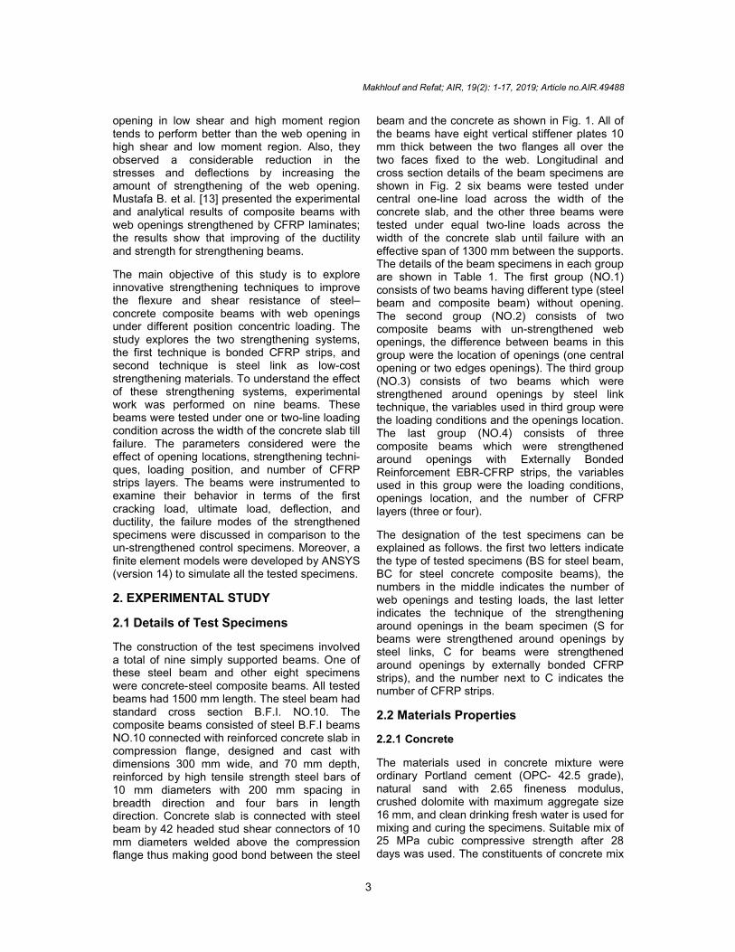
opening in low shear and high moment region tends to perform better than the web opening in high shear and low moment region. Also, they observed a considerable reduction in the stresses and deflections by increasing the amount of strengthening of the web opening. Mustafa B. et al. [13] presented the experimental and analytical results of composite beams with web openings strengthened by CFRP laminates; the results show that improving of the ductility and strength for strengthening beams.
The main objective of this study is to explore innovative strengthening techniques to improve the flexure and shear resistance of steel–concrete composite beams with web openings under different position concentric loading. The study explores the two strengthening systems, the first technique is bonded CFRP strips, and second technique is steel link as low-cost strengthening materials. To understand the effect of these strengthening systems, experimental work was performed on nine beams. These beams were tested under one or two-line loading condition across the width of the concrete slab till failure. The parameters considered were the effect of opening locations, strengthening techni-ques, loading position, and number of CFRP strips layers. The beams were instrumented to examine their behavior in terms of the first cracking load, ultimate load, deflection, and ductility, the failure modes of the strengthened specimens were discussed in comparison to the un-strengthened control specimens. Moreover, a finite element models were developed by ANSYS (version 14) to simulate all the tested specimens.
2. EXPERIMENTAL STUDY
2.1 Details of Test Specimens
The construction of the test specimens involved a total of nine simply supported beams. One of these steel beam and other eight specimens were concrete-steel composite beams. All tested beams had 1500 mm length. The steel beam had standard cross section B.F.I. NO.10. The composite beams consisted of steel B.F.I beams NO.10 connected with reinforced concrete slab in compression flange, designed and cast with dimensions 300 mm wide, and 70 mm depth, reinforced by high tensile strength steel bars of 10 mm diameters with 200 mm spacing in breadth direction and four bars in length direction. Concrete slab is connected with steel beam by 42 headed stud shear connectors of 10 mm diameters welded above the compression flange thus making good bond between the steel
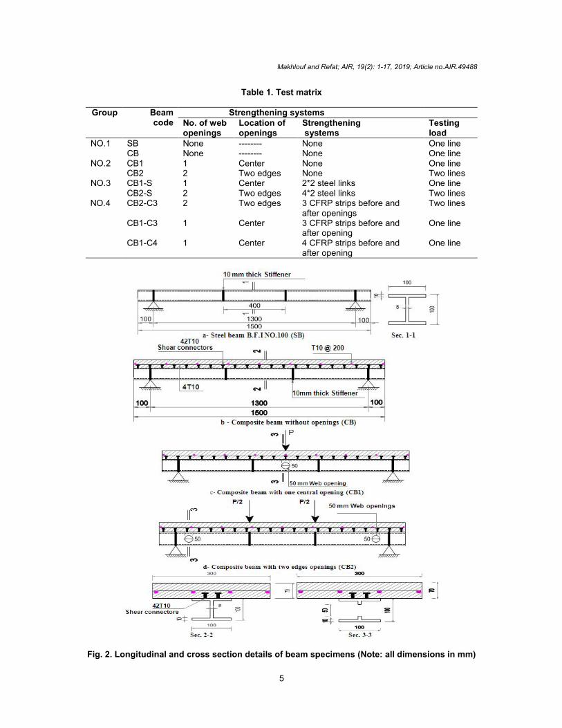
beam and the concrete as shown in Fig. 1. All of the beams have eight vertical stiffener plates 10 mm thick between the two flanges all over the two faces fixed to the web. Longitudinal and cross section details of the beam specimens are shown in Fig. 2 six beams were tested under central one-line load across the width of the concrete slab, and the other three beams were tested under equal two-line loads across the width of the concrete slab until failure with an effective span of 1300 mm between the supports. The details of the beam specimens in each group are shown in Table 1. The first group (NO.1) consists of two beams having different type (steel beam and composite beam) without opening. The second group (NO.2) consists of two composite beams with un-strengthened web openings, the difference between beams in this group were the location of openings (one central opening or two edges openings). The third group (NO.3) consists of two beams which were strengthened around openings by steel link technique, the variables used in third group were the loading conditions and the openings location. The last group (NO.4) consists of three composite beams which were strengthened around openings with Externally Bonded Reinforcement EBR-CFRP strips, the variables used in this group were the loading conditions, openings location, and the number of CFRP layers (three or four).
The designation of the test specimens can be explained as follows. the first two letters indicate the type of tested specimens (BS for steel beam, BC for steel concrete composite beams), the numbers in the middle indicates the number of web openings and testing loads, the last letter indicates the technique of the strengthening around openings in the beam specimen (S for beams were strengthened around openings by steel links, C for beams were strengthened around openings by externally bonded CFRP strips), and the number next to C indicates the number of CFRP strips.
2.2 Materials Properties
2.2.1 Concrete
The materials used in concrete mixture were ordinary Portland cement (OPC- 42.5 grade), natural sand with 2.65 fineness modulus, crushed dolomite with maximum aggregate size 16 mm, and clean drinking fresh water is used for mixing and curing the specimens. Suitable mix of 25 MPa cubic compressive strength after 28 days was used. The constituents of concrete mix

Makhlouf and Refat; AIR, 19(2): 1-17, 2019; Article no.AIR.49488
4
and its proportions are presented in Table 2. Three cubes, 150×150×150 mm, were cast at the same time as the specimens and cured alongside the specimens. 2.2.2 Steel bars and shear studs
The steel bars used to reinforcement of concrete slabs (middle reinforcement mesh) were deformed steel with nominal yield strength of 360 MPa. Also, 10 mm diameter of high tensile steel used for headed stud shear connectors were used to connected the steel beam and concrete slab with nominal yield strength of 460 MPa. The modulus of elasticity for all steel bars was 200 GPa. 2.2.3 CFRP sheets
Unidirectional CFRP were used for strengthening the openings region. Table 3 illustrated the mechanical properties of the CFRP. The CFRP
strips were bonded to the beam specimens with an epoxy resin, Sikdadur-330. For applying CFRP around the web openings in beam specimens, the bonded faces were cleaned until any dust was removed. Epoxy adhesive was applied to the steel face in thin layer and pre-cut CFRP strips layers were wrapped over it. The strips around steel beams cross section were passed firmly and rolled uniformly by plastic rollers to squeeze out excess epoxy and air bubbles. For applying more layers, epoxy was poured over the last layer and the procedure was repeated.
2.2.4 Epoxy
The epoxy used in this investigation was Sikadur-330 which is a product of Sika, it consists of two compounds, which were added together and mixed rapidly to assure its homogeneity before using. The mechanical properties of used epoxy are given in Table 4.
a- Shear connectors with10 mm diameters welded above the compression flange
b- Wooden form and reinforcement of
concrete slab
c- Casting of R.C. slab
Fig. 1. Preparation of composite beams
Makhlouf and Refat; AIR, 19(2): 1-17, 2019; Article no.AIR.49488
5
Table 1. Test matrix
Group Beam code
Strengthening systems No. of web openings
Location of openings
Strengthening systems
Testing load
NO.1 SB None -------- None One line CB None -------- None One line
NO.2 CB1 1 Center None One line CB2 2 Two edges None Two lines
NO.3 CB1-S 1 Center 2*2 steel links One line CB2-S 2 Two edges 4*2 steel links Two lines
NO.4 CB2-C3 2 Two edges 3 CFRP strips before and after openings
Two lines
CB1-C3 1 Center 3 CFRP strips before and after opening
One line
CB1-C4 1 Center 4 CFRP strips before and after opening
One line
Fig. 2. Longitudinal and cross section details of beam specimens (Note: all dimensions in mm)

Makhlouf and Refat; AIR, 19(2): 1-17, 2019; Article no.AIR.49488
6
Table 2. The constituents of concrete mix
Compressive strength Kg/cm
2
Cement (Kg/m
3)
Crushed dolomite (Kg/m
3)
Sand (Kg/m
3)
Water (Liter/m
3)
250 300 1200 600 175
2.3 Test Procedure
The tests were carried out in the Reinforced Concrete Lab at Benha Faculty of Engineering. The loading system consisted of rigid system of reaction frame, 100 ton maximum capacity, and hydraulic jack of 100 ton maximum capacity connected with electrical pump. The specimens were simply supported over a clear span of 1300 mm. Six specimens were prepared for testing under central line load across the width of the concrete slab. A steel spreader beam that was supported on two steel rollers covering the entire width of the top concrete slab was used to transfer the load to the tested specimen through two loading of 40 mm spacing at the mid span of the beam for author three beams. Vertical deflection, first cracking load and ultimate failure load, were recorded. Three linear variable differential transformers (LVDT) were used to record the deflection at three detected points, as shown in Fig. 3. Propagation of cracks was marked after each load increment up to failure.
2.4 Preparation of Strengthening Systems
2.4.1 Installation of bonded CFRP strips
In order to achieve a strong bond, the surface of the steel beams was prepared by air brushing to remove dust and fine particles. Following cleaning, a uniform thin layer of the epoxy adhesive was applied by palette knife to the surface of the steel beam. The CFRP strips were placed in position on the beam surface and pressed by hand. To ensure a good bond with steel, a uniform pressure was applied along the entire length of the strips. The CFRP strips with50 mm width and were placed around the steel beam cross section before and after each opening (Fig. 4a).
Table 3. Mechanical properties of CFRP
Property Value Fabric design thickness (mm) 0.13 Weight / area (g/m
2) 225
Strips fabric width (mm) 50 Tensile strength (N/mm2) 4300 Elasticity modulus (N/mm
2) 238000
Strain at failure 1.80%
2.4.2 Installation of steel links technique The proposed new strengthening system consisted of steel links which were locally fabricated using high tensile steel bars of 10 mm diameter fixed at both ends by two steel plates of 10 mm thickness and 30 mm width. Steel links were installed through the holes which penetrated the total concrete slab thickness and steel beam flanges. Links in the transverse direction was connected to the steel stall plates at top and bottom by steel nuts. Four steel links were used in vertical direction around each of web openings (Fig. 4b).
3a. Central one-line load across the width of the concrete slab
3b. Two-line loads across the width of the concrete slab
Fig. 3. Test set up & LVDT locations

Makhlouf and Refat; AIR, 19(2): 1-17, 2019; Article no.AIR.49488
7
a - CFRP-strips before and after web openings around cross section
b - Two steel-links before and after each web openings
Fig. 4. Description of different strengthening techniques (Note: all dimensions in mm)
Makhlouf and Refat; AIR, 19(2): 1-17, 2019; Article no.AIR.49488
8
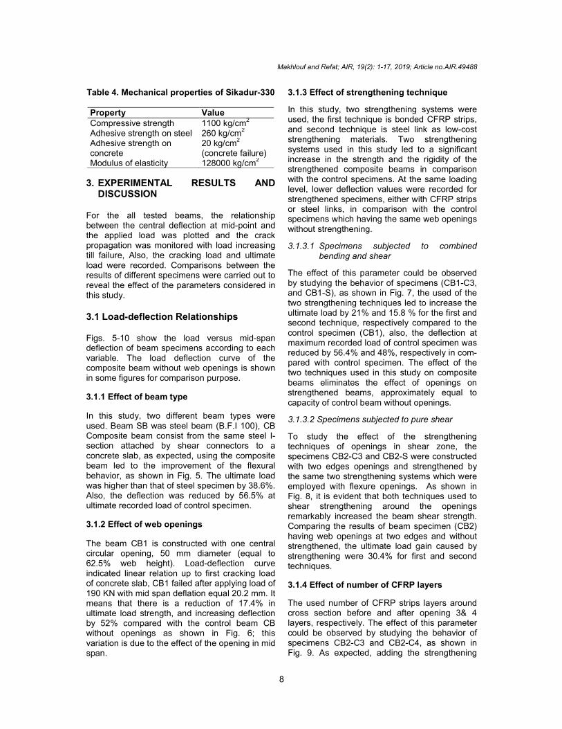
Table 4. Mechanical properties of Sikadur-330
Property Value Compressive strength 1100 kg/cm2 Adhesive strength on steel 260 kg/cm
2
Adhesive strength on concrete
20 kg/cm2
(concrete failure) Modulus of elasticity 128000 kg/cm
2
3. EXPERIMENTAL RESULTS AND DISCUSSION
For the all tested beams, the relationship between the central deflection at mid-point and the applied load was plotted and the crack propagation was monitored with load increasing till failure, Also, the cracking load and ultimate load were recorded. Comparisons between the results of different specimens were carried out to reveal the effect of the parameters considered in this study. 3.1 Load-deflection Relationships Figs. 5-10 show the load versus mid-span deflection of beam specimens according to each variable. The load deflection curve of the composite beam without web openings is shown in some figures for comparison purpose. 3.1.1 Effect of beam type In this study, two different beam types were used. Beam SB was steel beam (B.F.I 100), CB Composite beam consist from the same steel I-section attached by shear connectors to a concrete slab, as expected, using the composite beam led to the improvement of the flexural behavior, as shown in Fig. 5. The ultimate load was higher than that of steel specimen by 38.6%. Also, the deflection was reduced by 56.5% at ultimate recorded load of control specimen. 3.1.2 Effect of web openings
The beam CB1 is constructed with one central circular opening, 50 mm diameter (equal to 62.5% web height). Load-deflection curve indicated linear relation up to first cracking load of concrete slab, CB1 failed after applying load of 190 KN with mid span deflation equal 20.2 mm. It means that there is a reduction of 17.4% in ultimate load strength, and increasing deflection by 52% compared with the control beam CB without openings as shown in Fig. 6; this variation is due to the effect of the opening in mid span.
3.1.3 Effect of strengthening technique
In this study, two strengthening systems were used, the first technique is bonded CFRP strips, and second technique is steel link as low-cost strengthening materials. Two strengthening systems used in this study led to a significant increase in the strength and the rigidity of the strengthened composite beams in comparison with the control specimens. At the same loading level, lower deflection values were recorded for strengthened specimens, either with CFRP strips or steel links, in comparison with the control specimens which having the same web openings without strengthening.
3.1.3.1 Specimens subjected to combined bending and shear
The effect of this parameter could be observed by studying the behavior of specimens (CB1-C3, and CB1-S), as shown in Fig. 7, the used of the two strengthening techniques led to increase the ultimate load by 21% and 15.8 % for the first and second technique, respectively compared to the control specimen (CB1), also, the deflection at maximum recorded load of control specimen was reduced by 56.4% and 48%, respectively in com-pared with control specimen. The effect of the two techniques used in this study on composite beams eliminates the effect of openings on strengthened beams, approximately equal to capacity of control beam without openings.
3.1.3.2 Specimens subjected to pure shear
To study the effect of the strengthening techniques of openings in shear zone, the specimens CB2-C3 and CB2-S were constructed with two edges openings and strengthened by the same two strengthening systems which were employed with flexure openings. As shown in Fig. 8, it is evident that both techniques used to shear strengthening around the openings remarkably increased the beam shear strength. Comparing the results of beam specimen (CB2) having web openings at two edges and without strengthened, the ultimate load gain caused by strengthening were 30.4% for first and second techniques. 3.1.4 Effect of number of CFRP layers
The used number of CFRP strips layers around cross section before and after opening 3& 4 layers, respectively. The effect of this parameter could be observed by studying the behavior of specimens CB2-C3 and CB2-C4, as shown in Fig. 9. As expected, adding the strengthening

Makhlouf and Refat; AIR, 19(2): 1-17, 2019; Article no.AIR.49488
9
layers led to improve the flexural behavior. The ultimate load was higher than that of control specimen by 21% and 26.3% for strengthening number of CFRP layers 3 and 4, respectively. Also, the deflection was reduced by 56.4% and 70.3%, respectively at ultimate recorded load of control specimen. Comparing the results of web openings strengthened with different amount of CFRP strips, it can seen that increasing the number of layers increased the strength of beam specimens.
3.1.5 Effect of location of web openings
Two locations of web openings were used, the first location at mid-span (combined bending and shear) and the second location at the beam edges (shear zone). Fig. 10 shows the effect of the location for the circular web openings. This figure shows that the effect of the web openings at edges is slightly on the ultimate load because of bending moment in edge span equal to zero, while the effect of the web opening at center of beam (combined bending and shear zone) was very impact on ultimate load and central deflection.
3.2 Ultimate Strength
Table 5 shows the ultimate load (Pult.) recorded experimentally for the tested specimens. In flexure zone the use of steel links gave an increase of ultimate load by 15.8% of that recorded for control specimen and the use of CFRP strips with the different numbers of layers were three or four layers led to increase the ultimate load by 21% and 26.3%, respectively. Also, in shear zone the use of steel links and three layers of CFRP strips gave an increase of ultimate load by 15.8% of that recorded for control specimen and four layers increased of the ultimate load by 21% and 26.3%, respectively. Fig.11 shows a comparison between the tested
specimens with respect to cracking and ultimate loads. For control specimen CB1, the first crack was observed at 57.8% of the ultimate load. However, the first crack was observed at 52.2%, 52.1%, and 50% of the ultimate loads for strengthened specimens CB1-S, CB1-C3 and CB1-C4, respectively. The former result means that the strengthening systems conducted to increase the ultimate load of the tested specimens rather than the first crack load. Fig. 12 shows the effect of number of CFRP layers on ultimate and first cracking loads.
3.3 Cracking Behavior and Failure Mode For all specimens, the first crack was recorded, cracks propagation was monitored, and plane of failure was observed to investigate the cracking and failure behavior, the load value corresponding to cracking initiation (Pcr) is shown in Table 5. The tested specimens were loaded under one-line vertical load, failed due to flexure, flexural cracks started occurred randomly in the maximum moment region on the top RC slab; as the load increased, cracks formed along the entire length of the constant moment region, including the opening region. At failure, excessive deflection occurred due to yielding of steel beam at mid span which was followed crushed of the concrete slab at mid span. Yielding of steel beam occurred firstly at the bottom tee of the web opening due to concentration of tensile stresses, as shown in Fig. 13. For beams strengthened with CFRP strips, and with increasing the applied load, the failure was due to rupture of the FRP. The strengthening of the specimen caused a significant increase of the first crack load. Using steel links and CFRP strips led to increase the first crack load by 5% and 9%, respectively, in comparison with control specimen.
Table 5. Summary of test results
Beam code
1st.
Cracking Ultimate Ductility ratio Δul/Δcr
Ki Ku Stiffness degradation
Mode of failure Load
KN Defl. mm
Load KN
Defl. mm
KN/mm
SB ----- ----- 166 13 ------ ------ ------ ---------- Flexural failure CB 110 4.01 230 13.3 3.32 27.4 12.9 52.91 Flexural failure CB1 110 8.5 190 20.2 2.24 12.2 7.14 41.56 Flexural failure CB2 200 11.8 230 14.3 1.21 16.9 12 29.2 Shear failure CB1-S 115 4.95 220 14.3 2.89 23.2 11.2 51.66 Flexural failure CB2-S 215 7.25 300 14.1 1.94 29.7 12.4 58.16 Shear failure CB2-C3 210 6.33 300 13.2 2.09 33.2 13.1 61.51 Shear failure CB1-C3 120 3.95 230 14 3.54 30.4 10.9 63.97 Flexural failure CB1-C4 120 3.85 240 14.3 3.97 34.5 11.6 66.28 Flexural failure
Where: Ki = Pcr/Δcr, Ku = (Pul-Pcr)/(Δu-Δcr), and stiffness degradation = (Ki-Ku)*100/Ki

Makhlouf and Refat; AIR, 19(2): 1-17, 2019; Article no.AIR.49488
10
Fig. 5. Effect of beam type Fig. 6. Effect of web openings
Fig. 7. Effect of strengthening technique
(Central web opening)
Fig. 8. Effect of strengthening technique
(Two edges web openings)
Fig. 9. Effect of number of CFRP layers on load-deflection
relationships
Fig. 10. Effect of location of web openings

Makhlouf and Refat; AIR, 19(2): 1-17, 2019; Article no.AIR.49488
11
Fig. 11. Cracking and ultimate loads comparison for all tested beams
Fig. 12. Effect of number of CFRP layers on
Cracking and ultimate loads
The specimens tested under two-line vertical loads, failed under shear effect. Crack lines appeared at the shear zone. The number of cracks increased and followed by the formation of diagonal cracks. The crack width increased before failure, and the shear failure was sudden and initiated at points of the applied loads to the supports, also the strengthened specimens failed in shear with diagonal cracks initiated from the top corner of concrete slab towards the point load and from the bottom corner towards the support. Fig. 14 shows typical shear failure of beam specimens.
3.4 Ductility Ductility means the ability of a member to undergo inelastic deformations beyond the yield deformation without any considerable loss of load bearing capacity. The ductility of the specimens was considered as the ratio of the deflection at ultimate load to the deflection at first crack load as shown in Table 5. Generally, specimens strengthened by adding CFRP strips around web openings are better than specimens strengthened by steel links as shown in Fig. 15.
Fig. 13. Typical flexure failure for composite beams (loaded under one vertical)
Fig. 14. Typical shear failure for composite beams (loaded under two vertical)

Makhlouf and Refat; AIR, 19(2): 1-17, 2019; Article no.AIR.49488
12
3.5 Stiffness The un-cracked stiffness Ki and the ultimate stiffness Ku were obtained from the load-deflection values of the tested specimens, as presented in Table. 5. It shows that the un-cracked stiffness (Ki) is almost, increased for the all strengthened composite beams. Adding strengthening elements steel link, CFRP strips around openings led to increase Ki, while opening without strengthening led to decrease Ki in compared with control specimen without openings as shown in Fig. 16.
Fig. 15. Ductility ratio comparison for all tested composite beams
Fig. 16. Stiffness degradation comparison for all tested composite beams
4. FINITE ELEMENT ANALYSIS In this part, the tested specimens were simulated using the FEA program ANSYS (version 14). The numerical results of the simulated composite beams were compared with the experimental
results. The following summarizes details of the modeling approaches.
4.1 Element Types and Materials
Steel beam was modeled with 3D solid element SOLID 45, these eight node elements with three translational degrees of freedom per node. The concrete was modeled with a higher order 3-D element named SOLID 65. LINK180 is used to define reinforcement steel bars and steel links, the interface between the concrete slab and the steel beam was idealized by representing each stud as one nonlinear spring element COMBINE 39 at the actual location of the shear stud. SOLID185 is used to define CFRP sheets, while CONTACT 52 was used to descript the epoxy layer. Many materials were used in modeling the specimens such as concrete, steel reinforce-ment, CFRP sheets and epoxy resin Sikadur-330. These materials had the same properties used in experimental work. The compressive stress-strain relationship of concrete is con-sidered to be linear from zero to one-half the ultimate compressive strength, and the strain at the ultimate compressive strength ranges from 0.002 to 0.003. Reinforcement bars and shear connectors were modeled as a nonlinear and isotropic material. Epoxy sikadur-330 was modeled as linear isotropic material. CFRP strips were modeled by linear orthotropic material. The geometry and material properties of the specimens in section 2 were applied in this model.
4.2 Meshing and Boundary Conditions
A constructed FE model is shown in Fig.17. A relatively fine mesh having a maximum element length of 50 mm. The simply-supported beam condition was represented by restraining the nodes at supports.
4.3 Loading Model
In nonlinear analysis, the total load applied to a finite element model is divided into a series of load increments called load steps. At the completion of each incremental solution, the stiffness matrix is adjusted to reflect nonlinear changes in structural stiffness before proceeding to the next increment. ANSYS uses Newton-Raphson equilibrium iterations provide convergence at the end of each load increment within tolerance limits. In this study, convergence criteria were based on force and displacement, and the convergence tolerance limits were initially selected by the ANSYS program.

Makhlouf and Refat; AIR, 19(2): 1-17, 2019; Article no.AIR.49488
13
CFRP strips
(d) Composite beam CB2 (c) Composite beam CB1
Two edges web openings
One central web opening
Two line loads Concrete slab
One line load
Support
Steel beam
Support
Load
Support
(a) Steel beam SB
(e) Composite beam strengthened with CFRP strips around openings
(b) Composite beam CB1

Makhlouf and Refat; AIR, 19(2): 1-17, 2019; Article no.AIR.49488
14
Fig. 17. The developed FE models
Table 6. Comparison of the experimental results and finite element model
Beam code
Ultimate load (KN) Deviation
Deflection in mid span at ultimate load (mm) Deviation
Exp. FEA Exp. FEA SB 166 156 6.4 % 13 11.7 9.0 % CB 230 240 4.3 % 13.3 12.6 5.5 % CB1 190 180 5.5 % 20.2 17 18.8 % CB2 230 210 9.5 % 14.3 13 10 %
CB1-S 220 240 9 % 14.3 13.5 5.9 % CB2-S 300 320 6.6 % 14.1 12.8 9.1 %
CB2-C3 300 330 10 % 13.2 13 1.5 % CB1-C3 230 240 4.3 % 14 13 7.7 % CB1-C4 240 260 8.3 % 14.3 12.6 13 %
(f) Composite beam strengthened with steel links around openings
Steel links

Fig. 18. Comparison of experimental and FEM load
Fig. 19. Deformed shapes of finite element models
Makhlouf and Refat; AIR, 19(2): 1-17, 2019; Article no.
15
Comparison of experimental and FEM load – deflection curves
Deformed shapes of finite element models
; Article no.AIR.49488
deflection curves

Makhlouf and Refat; AIR, 19(2): 1-17, 2019; Article no.AIR.49488
16
4.4 Verification of the Finite Element Model
The experimental results obtained from testing of the tested specimens are compared with those obtained from the finite element modeling. The experimental and numerical results of load versus mid-span deflection are compared for each specimen, as shown in Fig.18. The typical deformed shape of the finite element models obtained by ANSYS is as shown in Fig. 19. Table 6 presents a comparison between the numerical and experimental ultimate loads. It can be noticed that the ratio of the numerical ultimate load to experimental one ranged from 1.043 to 1.1. It can be observed that ANSYS almost predicts a higher ultimate load compared to the load observed during experiments. This comparison shows a good agreement between experimental work and F.E.A. where identical results were obtained before yielding, while the difference was shown near failure for load-deflection curve while the first cracking load, ultimate load and ultimate mid-span deflection have acceptable data between them.
5. CONCLUSIONS
From the results and discussion above, the following conclusions can be made:
The concrete slab confers rigidity to steel beam. The presence of un-strengthened web openings in composite beams causes a significant reduction in the beam capacity.
The stiffness of the un-strengthened composite beams significantly decreases with the web opening.
Both the flexure and shear strength of composite beams with web openings were increased using the two strengthening techniques. The behavior of the beams against openings is improved.
The experimental results confirm that the two strengthening techniques of CFRP and steel links systems were practicable and led to increases the capacity of the composite beams with web openings.
In this study, the effect of CFRP and steel links delete the effect of openings on ultimate load where the ultimate load of strengthened beams was approximately equal to ultimate load of control beam without openings.
CFRP and steel links strengthening systems were effective in improving the
flexural strength of the tested specimens by 26.3% and 15.8%, respectively. Also, the deflections were reduced significally by 48% and 70.3% compared to the control specimen
Strengthening around edges web openings of composite beams using CFRP or steel links remarkably increased the shear strength, also, ultimate load capacity increased by 30.4%.
Applying the strengthening systems around openings used in this study decreased vertical deflection of composite beam, appropriately, especially in the plastic zone.
The two methods used for strengthening of composite beams with web openings in this research were effective to restore and improve the structural performance in terms of ductility, and stiffness.
Increasing the number of CFRP layers around openings leads to increase the stiffness of composite beam and therefore, increasing in ultimate load capacity.
This study approved that steel links technique gave more prominent simplicity of use, and low cost.
The numerical ultimate loads were in good agreement with those obtained from experimental results; the load-deflection relations obtained from numerical analysis have a linear relation up to crack load which almost coincides with the experimental values.
COMPETING INTERESTS
Authors have declared that no competing interests exist. REFERENCES 1. Cameira Neto TM. Analysis and design of
composite beams with web openings. Institute Superior Técnico, Lisbon University, Av. Rovisco Pais, 1049-001 Lisbon – Portugal; 2014.
2. Chen CC, Li CY, Kuo MC. Experimental study of steel reinforced concrete beams with web openings. 14
th World Conference
on Earthquake Engineering, Beijing, China; 2008.
3. Fattouh M, Shaker F, Shahat M. Strengthening of web opening in non-compact steel girders. IOSR Journal of Mechanical and Civil Engineering. 2015; 12(5)Ver. II:34-47.

Makhlouf and Refat; AIR, 19(2): 1-17, 2019; Article no.AIR.49488
17
[e-ISSN: 2278-1684, p-ISSN: 2320-334X] 4. Durga Prakash B, Gupta LM, Pachpor PD,
Deshpande NV. Strengthening of steel beam around rectangular web openings. International Journal of Engineering Science and Technology (IJEST). 2011;3(2). [ISSN: 0975-5462]
5. Redwood R, Cho SH. Design of steel and composite beams with web openings. Journal of Constructional Steel Research; 1993.
6. Chung KF, Ko CH, Wang AJ. Design of steel and composite beams with web openings – Verification using finite element method. Steel and Composite Structures. 2005;5(2-3):203-233.
7. Akwasi MA. Behavior of wide flange beams with reinforced web openings. M.Sc. Thesis, Southern Illinois University Carbondale; 2012.
8. Clawson RM, Darwin D. Tests of composite beams with web opening. Journal of the Structural Division, ASCE. 1982;108(1):145-162.
9. Hamoodi M, Hadi W. Test of composite beams with web openings. Engineering
and Technoogy Journal. 2011;29(10): 2073-2086.
10. Fam A. Macdougall C, Shaat A. Upgrading steel–concrete composite girders and repair of damaged steel beams using bonded CFRP laminates. Thin-Walled Structures. 2009;47:1122-1135.
11. Bouazaouia L, Jurkiewiezb B, Delmasa Y, Lia A. Static behavior of a full-scale steel – Concrete beam with epoxy-bonding connection. Journal of Engineering Structures; 2008.
12. Prakash BD, Gupta LM, Pachpor PD, Deshpande NV. Strengthening of steel beam around rectangular web openings. International Journal of Engineering Science and Technology (IJEST). 2011; 3(2):1130-1136. [ISSN: 0975-5462]
13. Dawood MB, AL-Saffar DH. Flexural behavior of steel concrete composite beam with web openings and strengthened by CFRP laminates. Inter-national Conference on Computational Plasticity. Fundamentals and Applications; 2015.
_________________________________________________________________________________ © 2019 Makhlouf and Refat; This is an Open Access article distributed under the terms of the Creative Commons Attribution License (http://creativecommons.org/licenses/by/4.0), which permits unrestricted use, distribution, and reproduction in any medium, provided the original work is properly cited.
Peer-review history: The peer review history for this paper can be accessed here:
http://www.sdiarticle3.com/review-history/49488