strength of layer structural elements and modelling of fracture
TRANSCRIPT

KAUNAS UNIVERSITY OF TECHNOLOGY
Nerijus Meslinas
STRENGTH OF LAYER STRUCTURAL ELEMENTS AND MODELLING OF FRACTURE
Summary of Doctoral Dissertation
Technology Sciences, Mechanical Engineering 09T
Kaunas, 2005

Dissertation was prepared at Department of Mechanics of Solids, Kaunas University of Technology from 1999 to 2003. Academic Supervisor
Prof. Dr. Habil. Antanas ŽILIUKAS (Kaunas University of Technology, Technology Sciences, Mechanical Engineering 09T).
Council of Mechanical Engineering Science trend:
Prof. Dr. Habil. Juozas ATKOČIŪNAS (Vilnius Gediminas Technical University, Technology Sciences, Mechanical Engineering 09T);
Prof. Dr. Habil. Bronius BAKŠYS (Kaunas University of Technology, Technology Sciences, Mechanical Engineering 09T);
Prof. Dr. Habil. Mykolas DAUNYS (Kaunas University of Technology, Technology Sciences, Mechanical Engineering 09T);
Prof. Dr. Habil. Remigijus JONUŠAS (Kaunas University of Technology, Technology Sciences, Mechanical Engineering 09T);
Prof. Dr. Habil. Rimantas KAČIANAUSKAS (Vilnius Gediminas Technical University, Technology Sciences, Mechanical Engineering 09T).
Official Opponents:
Prof. Dr. Habil. Jonas BAREIŠIS (Kaunas University of Technology, Technology Sciences, Mechanical Engineering 09T);
Prof. Dr. Habil. Petras ILGAKOJIS (Lithuanian University of Agriculture, Technology Sciences, Mechanical Engineering 09T).
The official defence of the dissertation will be held at 11.00 a.m. on 4 th. March 2005, at the Council of Mechanical Engineering trend public session in the Dis-sertation Defence Hall at the Central Building (K. Donelaičio g. 73, room No. 403, Kaunas) of Kaunas University of Technology. Address: K. Donelaičio g. 73, 44029 Kaunas, Lithuania. Tel.: (370) 37 300042, fax: (370) 37 324144; e-mail: [email protected]
The sending out of the summary of the dissertation is on 4 th. February, 2005.
2
The dissertation is available at the library of Kaunas University of Technology.
KAUNO TECHNOLOGIJOS UNIVERSITETAS
Nerijus Meslinas
SLUOKSNIUOTŲ KONSTRUKCINIŲ ELEMENTŲ STIPRUMAS IR IRIMO MODELIAVIMAS
Daktaro disertacijos santrauka
Technologijos mokslai, mechanikos inžinerija 09T
Kaunas, 2005
3

Disertacija rengta Kauno technologijos universiteto Deformuojamų kūnų mechanikos katedroje 1999 – 2003 metais. Mokslinis vadovas
Prof. habil. dr. Antanas ŽILIUKAS (Kauno technologijos universitetas, technologijos mokslai, mechanikos inžinerija 09T).
Mechanikos inžinerijos mokslo krypties taryba:
Prof. habil. dr. Juozas ATKOČIŪNAS (Vilniaus Gedimino technikos universitetas, technologijos mokslai, mechanikos inžinerija 09T);
Prof. habil. dr. Bronius BAKŠYS (Kauno technologijos universitetas, technologijos mokslai, mechanikos inžinerija 09T);
Prof. habil. dr. Mykolas DAUNYS (Kauno technologijos universitetas, technologijos mokslai, mechanikos inžinerija 09T);
Prof. habil. dr. Remigijus JONUŠAS (Kauno technologijos universitetas, technologijos mokslai, mechanikos inžinerija 09T);
Prof. habil. dr. Rimantas KAČIANAUSKAS (Vilniaus Gedimino technikos universitetas, technologijos mokslai, mechanikos inžinerija 09T).
Oficialieji oponentai:
Prof. habil. dr. Jonas BAREIŠIS (Kauno technologijos universitetas, technologijos mokslai, mechanikos inžinerija 09T);
Prof. habil. dr. Petras ILGAKOJIS (Lietuvos žemės ūkio universitetas, technologijos mokslai, mechanikos inžinerija 09T).
Disertacija bus ginama 2005 m. kovo 4 d. 11.00 val. viešame mechanikos inžinerijos mokslo krypties tarybos posėdyje, kuris įvyks Kauno technologijos universitete, centrinių rūmų disertacijų gynimo salėje (K. Donelaičio g. 73, 403 a., Kaunas). Adresas: K. Donelaičio g. 73, 44029, Kaunas. Tel.: 8 37 300042, faksas: 8 37 324144; el. paštas: [email protected]
Disertacijos santrauka išsiųsta 2005 m. vasario mėn. 4 d.
Su disertacija galima susipažinti Kauno technologijos universiteto bibliotekoje.

5
INTRODUCTION
Layer structural elements usually are produced by connecting two or more different materials (e.g.: fibber – matrix structures, particles – matrix structures). Strength and elasticity properties of layer structural elements are different from properties of initial materials. In some cases, due to mechanical interaction among different components, those properties of layer structures can be even better than properties of strongest element’s material. Therefore layer structures should be considered as a part of larger construction but not as a ma-terial of it.
Technological defects are one of the most important reasons when layer structures show worse properties and decompose earlier than expected. During exploitation of those structures, small technological defects can grow into criti-cal. Defects of material’s structure (fracture, voids, and weak bonds) are cause of crack’s growth while stresses are quite insignificant. Growth of cracks gradually lowers level of integrity and some of components are affected by increased strains. That determinates constant fracture of layer element and in some cases can cause early breakage of whole structure functionality.
High interlayer stresses are typical for spatial stresses state of layer structural elements. They are caused by peculiar anisotropy of such structures. High interlayer stresses cause delaminating in layer structures and fracture zone grows rapidly. That is initial indication of whole structure’s fracture. Therefore it is important to determinate interlayer stresses in order to examine possibili-ties of structural layer element.
Object of the Research: Strength of layer structural elements with defects and methods of
strength evaluation; characteristics of structural element’s layers and interlayer zones, influencing strength of whole structure, are investigated in this research.
Cracks propagation in layer structural elements; influence of crack’s po-sition direction of interlayer and way of layering on process of fracture; de-pendence of plastic deformations zone, located next to crack’s head, size upon thickness of layer are investigated too.
Influence of remote plastic deformations zones on fracture is analyzed in details.
Goals of the Research Fracture of layer structural elements depends on fracture of different
layers and interlayer zones. Cases of layer structural elements fracture are ana-lysed in this research. Due to materials heterogeneity and technologies of manufacturing, medium layer (interlayer) appears. This layer influences defor-mation, stresses distribution and fracture of the structure. Often medium layer is

6
weakest link of structural layer element and interlayer fracture called delamina-ting can appear. Therefore it is aimed:
• Determinate suitability of fraction criterions for evaluation of layer structural element’s strength and fracture;
• Propose mathematical model for predicting of layer structural ele-ment’s fracture;
• Analyse and compare analytical and numerical models of layer struc-tures;
• Propose methodology for analysis of fracture process applying finite elements.
Scientific Novelty Mathematically model of layer structural element fracture is formulated
for a case, when size of plastic deformations zone is similar to thickness of a layer. This model allows calculation of layer structural element’s plastic defor-mations and size of crack’s head.
Presented description of development of plastic deformation zones is based on classical laws of fraction mechanics. This description is verified using means of Finite Elements Method (FEM) and experimentally.
Proposed methodology for modelling of fracture process is based on mathematical equations for calculation of plastic deformations zone and nu-merical finite elements method (FEM). This methodology will have essential meaning for development of new layer structures characterized by better me-chanical properties.
Presented for the Defence There are no universal criterions for evaluation of fracture initiation in
layer structural elements. Interlayer of such structures influences field of stress distribution next to crack’s head due to rise of stress intensity coefficient. When crack is located in interlayer zone, distribution of stresses in some angles de-pends on elasticity modules of structure’s materials.
Interlayer of layer structural elements influences field of stress distribu-tion next to head of crack, because coefficient of stress intensity increases.
Fracture in layer structural element is affected by mechanical character-istics of inserted layer, interlayer bonding force, thickness of inserted layer, angle of crack’s head rising.
Fracture process in layer structural elements are not affected by remote zone of plastic deformations in case of transverse bending, but fracture initiates in inserted layer next to remote zones of plastic deformations in case of pure bending.
Method of finite elements can be used for analysis of layer structural elements with some limitations only.

7
Original methodology for usage of FEM in evaluation of layer structural element’s fracture is composed. It includes mathematical calculation of plastic deformation zones and does not depend on mesh of finite elements.
Structure and Volume of the Dissertation: Dissertation consists of an introduction, four chapters, conclusions, list
of author’s publications and list of references. Total volume of dissertation is 111 pages, 80 pictures and 11 tables.
CONTENT OF THE DISSERTATION WORK 1 REVIEW OF LITERATURE
Quantitative criterions for evaluation of tensile as well as elastic fracture
of layer structural elements are not perfectly universal in case of combinative load, but they are acceptable for evaluation of designed structure’s state and for obtaining of main mechanical characteristics of layer structural element. Dif-ferently from metal elements, layer structural elements are heterogeneous and anisotropic. Macrostructure of those elements is designed by bonding one layer on another. Layers can have different mechanical properties.
Layer is assumed as the main structural element in most of engineering calculations of layer structural elements. Layers are characterised by elastic constants (obtained experimentally or using methods of micromechanics), ulti-mate strength and geometry.
Analysis of recent scientific works, where mechanical behaviour of layer structural elements is discussed, shows that there are no universal criteri-ons for describing beginning of fracture. Criterions of strength and fracture are based classical theories of strength and fracture mechanics.
Fracture can be described using energetic criterion J-integral and condi-tions of fracture can be described by critical value of the J-integral in evaluation of elastic – plastic fracture behaviour of layer structural elements. 2 DETERMINATION OF LAYER STRUCTURAL ELEMENT’S FRAC-TURE LAWS
Comparison analysis of non-local fracture criteria Comparison analysis of non-local fracture criteria is performed by re-
search of two problems (fig. 1 and fig. 2). Analysis is preformed for three types of non-local fracture criteria: average stress fracture criterion, minimum stress fracture criterion and fictitious crack fracture criterion.
Every problem of strength and fracture can be assumed as equality of specific shape function of general non-local force. Criteria of comparison con-

sist of two parameters: typical length and ultimate stress or critical stress inten-sity factor.
In practice, there are several problems of strength and fracture mechan-ics that can not be solved using classical conditions of strength and fracture. Some examples of those problems are shown in figures 1 and 2.
q
q
a y
Fig. 1 Plate with hole of radius a
Example of small defect effect on strength is shown in fig. 1. Here infi-
nite elastic plate with round hole is loaded by infinite load q. It is known form theory of elasticity, that maximum stresses are equal to 3q, are located in ana-lyzed point y and do not depend on radius of hole a. Strength of the plate is evaluated by fracture criterion and will be equal to one third from for plate without of crack (continuous line in fig. 1).
cσσθθ = cσ
q
q
2a y
Fig. 2 Plate with crack’s length a
Another example of small defect effect on strength is plate with 2a crack
(fig. 2). Linear elasticity is characterized by value of the stress intensity factor ( ) aqyKI π= . From the linear fracture mechanics it is known that every frac-
ture criterion can be given in form ( ) ICI KyK = .
8

Those two expressions can be used for theoretical dependence of plate’s strength on length of the crack. Strength of the plate is increase till the infinity if length of the crack is decreasing to the zero. However experiments with short cracks show that strength has finite values.
Three non-local criteria for solution of problems in plane Fracture criteria, based on average stress for characteristic length, can be
obtained integrating in direction of . Then criterion has simplest form: 0θ
( )( ) Cd
dyd
σρθρησθθ =+∫1
01
1 . (1)
Here is strength of specimen without concentrators, when unitary load is applied; d
Cσ1 is constant of material, related with criterion of length.
The second fracture criterion is based on minimum stress for character-istic length. Minimum stress criteria can be presented in simple form, when direction corresponds with maximum of function (1): 0θ
( )( ) Cdy σθρησθθρ
=+≤≤
00 2
min (2)
The third fracture criterion is based on fictitious crack model in charac-teristic length. It is assumed that fictitious crack exist, has characteristic length
and starts in point of specimen y. After some manipulations and assuming that direction of the crack is known, criterion of fictitious crack obtains form:
3d0θ
( ) ( )( )( ) ICII KdyKyK =+ 03,min θη (3) Here and are constants of material, ICK 3d ( )yKK III = and
are factors of stress intensity on sides of the fictitious crack, oriented in direction
( )( θη312 dyKK I += )( )θη .
Every of those three criteria involve two parameters: characteristic length and parameter of strength or . id Cσ ICK
Analyzing strength of plate with central crack, straight crack of length is located in infinite plate (fig. 2). Beginning of a coordinate system a2 ( )21, xx
is superposed with centre of the crack. If uniform stress σ acts parallel to axis , near head of the crack 2x ( )0,122 xσ can be approximated asymptotically and
obtains form:
( ) ( )22122 0,axa
xKxI
II
−=
πσ . (4)
9

Direction of the maximum tensile stresses corresponds with direction of crack’s propagation x and all non-local criteria of fracture can be used in sim-ple expressions (1), (2) and (3). Strength of plate with central straight crack can be written using average stress fracture criterion (1) and expression (4):
1
11
1 ηηπσ
+=
dK CIC . (5)
Here is normalized length of crack. Besides, if , ulti-mate strength of the plate with crack is reached.
( 11 / daa +=η ) Cq σ=
Then relation between normalized strength of plate and length of crack can be obtained from equations (4) and (5).
1
1
11
ηη
σ +−
=C
q (6)
Equation (6) says that when 1/ →Cq σ ( )001 →→ aη for a short crack and when 0/ →Cq σ ( )∞→→ a11η for a long crack.
Strength of plate with central straight crack can be written using mini-mum stress fracture criterion (2) and equation (4). Equalities of critical inten-sity of stresses for length of the crack are:
( )222 1 ηηπσ += dK CIC . (7)
Here 2
2 daa+
=η . Analyzing equations (4), (7) and from condition of ultimate
strength (then ) it can be obtained: qC =σ
221 η
σ−=
C
q (8)
Equation (8) also shows that when 1/ →Cq σ ( )002 →→ aη for a short crack and when 0/ →Cq σ ( )∞→→ a11η for a long crack.
Analyzing strength of plate with central straight crack by fictitious crack fracture criterion, fictitious crack with length is formatted next to head of the main crack . Factor of stress intensity for such formatted crack is
3da2
⎟⎠⎞
⎜⎝⎛ +=
23daKI πσ . Criterion (3) gives ⎟
⎠⎞
⎜⎝⎛ +=∞
23daqKIC π .
0=a and 2/3dK CIC πσ=∞ for a plate without crack. Rewriting linear prognosis of fracture strength mechanics in normalized form gives equation, which can be compared with other generalized criteria of fracture in the same system of coordinates.
10

2
2
3
3 12
1
CC
qqση
ησ
−−
= (9)
Common non-dimensional parameters of crack’s length ( )0/ daa +=η and stress are introduced before results in the same coordinates are shown.
Cq σλ /=
Dotted line in fig. 3 corresponds to prognosis of linear fracture mechan-ics. Non-local criteria give when 1/ →Cq σ 0→η for narrow cracks, while criterion of linear fracture mechanics and criterion of fictitious crack give unre-alistic prognosis . ∞→Cq σ/
In case when 5.0≈η , for fracture criteria of average stress and fictitious crack. Description of this case is incorrect using criterion of minimum stresses and criterion of linear fracture mechanics.
6.0...5.0/ ≈Cq σ
0
0,1
0,2
0,3
0,4
0,5
0,6
0,7
0,8
0,9
1
0 0,1 0,2 0,3 0,4 0,5 0,6 0,7 0,8 0,9 1
VĮIK
FPIK
MĮIK TIMK
λ
η Fig. 3Comparison of fracture criteria for a plate with a central hole
As can be seen, all non-local fracture criteria evaluate cases with long
crack’s quite good ( when 0/ →Cq σ 1→η ). Summarising it can be said that average stress fracture criterion is more
precise for fracture evaluation of the plate with central hole. Analysing a circular hole of radius a in an isotropic infinite plate (fig.
1), beginning of coordinate system a( )21, xx coincides with centre of the hole. If
uniform tensile stress σ acts parallel to axis , then the distribution of the
normal stress along the axis is given by the expression: 2x
( 0,122 xσ ) 1x
11

( ) 4
1
2
1
122
23
2110,
⎟⎟⎠
⎞⎜⎜⎝
⎛+⎟⎟
⎠
⎞⎜⎜⎝
⎛+=
xa
xax
σσ . (10)
The stress distribution in the non-dimensional coordinates does not de-pendent on the hole size, and the stress concentration factor at the edge of hole does not dependent on the hole radius too, . However, the size of stress concentration region depends on the hole’s radius.
( ) σσ 30,22 =a
Due to average stress fracture criterion, strength of a plate with circular hole can be calculated by substituting equation (1) into (10) and performing the integration. Fracture criterion for the most stressed point at the plate with a crack (a, 0) is:
( )( )211 21
2ηησ ++
=C
q (11)
For large values of the radius a (when ) reduction of plate’s
strength is caused by the hole and evaluated by factor
11 →η
31
→C
qσ
, while for
small values of a (when 01→η ) no strength reduction is predicted . 1/ →Cq σAccording to minimum stress fracture criterion, strength of a plate with
circular hole can be calculated from equation (2) and (10):
42
22 322
ηησ ++=
C
q (12)
Equation (12) obtains values 31
→C
qσ
and 1→C
qσ
for big holes
and small holes . 12 →η 02 →ηAnalyzing strength of plate with circular hole by fictitious crack frac-
ture criterion, fictitious crack with length is formatted in point (a, 0) in di-rection of axis. Concentrator of stresses has asymmetric form. According a linear elastic solution of such shape concentrator:
3d
1x
( )321ησ f
q
C= . (13)
For hole of radius ∞→a , and if geometric limits exist, anal-ogy for half-plate with crack on it’s side and load
13 →ησ3 can be written
12

0
0,1
0,2
0,3
0,4
0,5
0,6
0,7
0,8
0,9
1
0 0,1 0,2 0,3 0,4 0,5 0,6 0,7 0,8 0,9 1
VĮIK FPIK MĮIK TIMK
λ
η Fig. 4 Comparison of fracture criteria for a plate with circular hole
Comparison of fracture criteria for a plate with circular hole is made us-
ing normalization C
qσ
λ = and 0da
a+
=η . Fictitious crack fracture criterion is
not exact for bid radius holes. Results of comparison are presented in figure 4. Average stress fracture
criterion and fictitious crack fracture criterion give similar results for plates with symmetrically loaded central crack.
Average stress fracture criterion gives best results for analysed exam-ples. Therefore this criterion will be used in further analysis of layer structural element’s strength and fracture.
Propagation of Crack Propagation of cracks is illustrated by special shape samples composed
of two elements glued with polymeric adhesives. Intensity of released energy GI for certain length of a crack for those specimens can be given as
( )⎥⎥⎦
⎤
⎢⎢⎣
⎡+
+⎟⎠⎞
⎜⎝⎛=
hhaa
EBBFGI 3
1242 3
20
2
. (14)
Since values and are not big, does not depend on the
length of crack a, in condition if proportion is constant. Therefore dur-ing the experiments, aiming to keep proportion constant, shape of specimens should have oblique surface. 7° angle was used (fig. 5) for obtaining constant value of proportion .
0a h3/1 IG32 / ha
32 / ha
32 / ha
13

a
h 7°
F
F
Fig. 5 Layer specimen for analysis of crack’s opening
Proportion should remain constant, if length of sample is much
larger then height (equation 14). Therefore, aiming to eliminate influence of geometric parameter h to the opening of crack, height of the specimen should start increasing from the point where analysis of crack opening is started.
32 / ha
Proportion changes non-linearly, as it is shown in fig. 6. Since producing of such shape surface is technically difficult, it can be simplified, because insignificant deviation of proportion values will not affect result of calculations badly.
32 / ha
0
5
10
15
20
25
0 2 4 6 8 10 1
a
2
, mm
h, m
m
1
2
3
Fig. 6 Dependence geometric parameter h on length of crack a
Curves 1, 2 and 3, shown in fig. 6, are obtained with different values of
proportion, respectively: 1 – , 2 – and 3 – . After linear approximation and simplifying value of specimen‘s
surface angle is obtained approximately 7°. In this case dependence of parame-ters and F, when crack is located in middle part of the specimen will be:
01.0/ 32 =ha 1.0/ 32 =ha3.0/ 32 =ha
IG26107,12 FGI ⋅⋅= − . (15)
Loading layer structural elements with increasing load (work of cracks propagation), marginal value can be obtained than crack is growing. Speed of crack’s growing can be obtained analyzing irregularities of fracture surface in head of crack.
IG
IcG
14

Stopping of a crack usually is unpredictable. If crack stopped, force of crack’s propagation can be calculated using value of used load. aG
Influence of Interlayer Orientation to the Process of Fracture Three main cases of crack’s surface movements, when different loads
are applied, are shown in fig. 7. First type of cracks surface movement and frac-ture of the first type start in isotropic solid with a crack located in plane Oxz when surfaces of fracture move away from each other and displacement of sur-face planes are oriented along axis y in reverse directions (fig. 7 a). In case of the second type fracture (fig. 7 b), displacements of fracture planes are oriented along axis x perpendicularly to the head of crack and case of shear is obtained. In the third case of fracture (longitudinal shear), planes of fracture move along axis z and parallel to the head of crack (fig. 7 c).
a b c
x
y
z
y y
x x
z z
F
F
F
F F
F
Fig. 7 Cases of fracture and displacements of crack’s planes
Lamination of practical structures is possible in all directions. Compact
layer specimen can be presented as an example. It is laminated parallel to hori-zontal, profile and frontal plates. Fracture of specimens will depend not only on direction of lamination, but also on direction of loading forces F.
Dependence of fracture process on inserted layer mechanical properties, interlayer bonding force and thickness of inserted layer is analysed in this chap-ter too.
For the first case of fracture (fig.7 a), analyzed specimens are loaded by concentrated forces parallel to axis y.
Fracture type of horizontally laminated specimen is influenced by me-chanical properties of inserted layer, thickness of this layer and force of bond-ing with the main material. If thickness of inserted material is smaller than ra-dius of plastic deformation areas and main material is mechanically stronger, zone of plastic deformation grows even by 20%.
15
Fracture under load starts next to head of crack in specimen layered par-allel to profile plane. Crack changes its direction when reaches inserted mate-

rial (it grows into two cracks in ideal case). Change of crack’s direction is caused by shape of plastic deformations area and by mechanical properties of inserted material.
Case, shown in figure 7 c, is the most complicated. Results of fracture evaluation depend on type of loads. There are two possible ways to apply force. In the first case force is applied to both layers and they are deformed equally. Another case is when force is divided into two components and applied to each layer separately; loading with equal forces is used.
In analysis of the second type of fracture (fig. 7 b) specimens are loaded with concentrated forces parallel to axis x. In this case fracture of iso-tropic material is caused by shear and starts in the weakest point of specimen (next to a stress concentrator). Major shear stresses are dominant and direction of specimen lamination does not matter.
Fig. 7 shows typical case of pure shear. Surfaces of crack will slide on each other in plane Oxz along direction of load. Fracture does not depend on thickness of layer and can be calculated by classic formulas of the second type of fracture and criterions of second type fracture ( ) can be used. IIK
In case, shown in figure 7, shear appears next to stress concentrator and surface of shear is anisotropic. If thickness of inserted layer is similar to thick-ness of surrounding layers, influence of inserted layer to fracture process is insufficient and can be neglected in most of engineering calculations.
Results of fracture calculations depend on type of loading for the last case. First loading type is than specimen is deformed equally and second is, than equal forces are loaded to different layers. In the first case fracture starts due to shear in more brittle material and process of fracture starts when values of forces F are lover. Alternatively, in the second case, fracture starts in me-chanically stronger material and will followed by two shear surfaces perpen-dicular to each other.
Analysing the third type of fracture (fig. 7 c), specimens are loaded by concentrated forces oriented parallel to axis z.
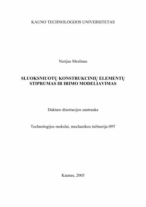
For a type of laminating typical case of the third type of fracture can be obtained as subject of inserted layer’s thickness. Surfaces of crack will slide on each other in plane Oxz in direction of load. Fracture does not depend on thick-ness of inner layer and can be calculated by classic formulas of the third type of fracture and criterions of third type fracture can be used. Point of stress concen-tration moves into point K as it is shown in fig. 8. Distance till the head of crack, used in equation, can be calculated using this formula: IK
22αctghaa ⋅−=′ .
16
a - h/2⋅ctgα/2
h
a
α
K
y
x
Fig. 8 Development of crack than stronger layer is inserted
Force of interlayer bonding has largest influence to process of fracture in
case of laminating. If value bonding force is high and mechanical properties of inserted layer is significantly lower than characteristics of other layers, crack will branch in inner layer (plane Oyz) after fracture of layer with a stress con-centrator.
In case shown in fig. 7 c, process of fracture will start next to head of crack in layer of more brittle material. Weaker layer will be deformed plasti-cally. In process of crack’s growing it will be cut by edge of crack in brittle material.
Still there is no universal strength or fracture criterion capable to de-scribe exactly all types of fracture. Need of such criterion is undoubted, be-cause real structures can be loaded by combinative forces. Prognostication of strength or fracture is even more complicated in this case.
Main Results
1. Non-local criteria of fracture consist of two parameters: typical length and ultimate stress or critical stress intensity factor. Due to those parameters, criteria of fracture are divided into three types: criterion of average stress frac-ture, minimum stress fracture criterion and fictitious crack fracture criterion. Criteria of average stress fracture describe layer structural elements with de-fects more exactly.
2. Analysis of layer structural elements crack’s propagation showed, that specimen (model) has be prepared in a way that ratio of specimen height and depth of crack should remain constant.
3. All three types of fracture are influenced not only by direction of lay-ering, but also by mechanical properties of inserted layer, force of interlayer bonding, thickness of inserted layer, angle of crack’s head.
17

3 COMPARISON OF ANALYTIC AND NUMERICAL METHODS AND
CREATION OF MATHEMATICAL AND FEM MODELS
Experiments and Mathematical Modelling
Most of structural elements are loaded by bending during exploitation. Often constructions are loaded in a way that pure point bending is created. Such type of loading reduces maximum moment of bending and distributes stresses more equally in every cross-section. Layer structural elements, loaded by trans-versal bending, fracture in same manner as homogeneous elements: crack opens at the concentrator of stresses in the first layer, later it increases through the second layer and so on. Loading layer structure by pure point bending, fracture starts in inner material close to interlayer. In case of strong adhesion, crack in-creases in inserted material along layers, and in case of weak adhesion, delami-nating begins.
Goal of experiments: determinate emerging of secondary areas of plas-tic deformations in inserted layer in case of pure point bending and analyse influence of those zones on direction of crack’s growth.
Methodology of Experiments: In classical fracture mechanics calculations of homogeneous isotropic
materials are limited to calculations of plastic deformation’s zones where stresses are higher than ultimate yield limit. It is also known that decrease of stresses is exponential receding from head of a crack. Even in distance from head of crack equal to 5 – 10 values of radius of plastic deformation areas, de-crease of stresses is 2 – 3 times and stresses are lower then limit of ultimate yield. Deformations at head of a crack in case of plane state of stresses are cal-culated:
lr
lr
rEKI
21
1
2sin31
2cos
22
+
+Θ+
Θ=
πε . (16)
In case of plane deformations:
( )
lr
lr
rEKI
21
1
2sin321
2cos
222
+
+Θ+−
Θ= µ
πε . (17)
Factor of pressure intensity for beam on two supports in case of pure point bending:
IK
18

( )43
1 Ybt
LLFKI−
= . (18)
Here L is distance between supports, b is height of specimen, t is thick-ness of specimen, L1 is distance between supports of medium element.
⎟⎟⎠
⎞⎜⎜⎝
⎛⎟⎠⎞
⎜⎝⎛+⎟
⎠⎞
⎜⎝⎛−=
2
4 839.5396.31494.3bl
blY . (19)
If layer of material characterized by few times lower limit of yield is in-serted in distance from head of crack similar to value of radius of plastic de-formation areas, secondary zones of plastic deformations emerge. Change of normal stresses in any layer of structural element, travelling from one layer into another, is proportional to proportion of elasticity modules of those layers:
i
iii E
E 11
++ = σσ . (20)
When load is increasing, stresses reach critical values and process of fracture starts. Crack grows in direction of largest deformations. In same time, secondary zones of plastic deformations emerge in stressed layer. Crack grows perpendicularly to a plane of stressed layer. Head of crack changes its direction when reaches inner layer with already emerged zones of plastic deformations. In ideal case, crack propagates into two cracks, because two zones of ultimate plastic deformations are formatted.
Proceeding of Experiments: Layer specimens in case of bending collapse similarly to isotropic. Main
difference is that layer structures delaminate before they collapse. Fracture of layer structures under bending is not main aim of those experiments, but illus-trates differences of fracture due to type of load.
Load in case of transversal bending (force F ) is applied on the centre of specimen in reverse side from a cut. Load in case of pure point bending is ap-plied in the same way as in transversal bending, but using symmetric medium element. Here load is divided into two components ( ). 2/F
Experiments with First Type of Specimens
19
In experiments of pure point bending, top support is changed by sym-metrically located supports. Distance between centres of supports is 5 cm. Specimen is deformed and delaminating starts between first and second layers. Signs of fracture emerge in the first layer and areas of secondary plastic defor-mations develop in the second layer. When force reaches critical limit, first layer collapse and appearance of cracks in second layer is caused by areas of secondary plastic deformations. Cracks appear not in a point of initial crack, but in zones of secondary plastic deformations. Comparing stresses on head of a crack and stresses in areas of secondary deformations, located in some dis-

tance, it can be noticed that stresses analysed areas are signally lower, however stresses exceed yield stresses in interlayer.
Experiments with Second Type of Specimens In experiments of pure point bending, top support is changed by sym-
metrically located supports. Distance between centres of supports is 37 mm. Specimen is deformed and delaminating starts between first and second layers. Areas of secondary plastic deformations develop in the inner layer. Inner layer collapses in areas of secondary deformations perpendicularly to layers. First layer collapses if load is increased and maximum limit is reached. If specimen is even more deformed, second and third layers delaminate.
Analysis of Results:
Forces of bending strength for structure ( F ), forces of bending strength for inserted element ( ) and radius of secondary plastic deformation’s areas (
IFr ) were measured during experiments.
Strength limits in bending for the first type of specimens were obtained: for structure 2819.5222 ±=F N; for inserted element N. 2165.4603 ±=IF
Strength limits in bending for the second type of specimens were ob-tained: for structure 1584.5025 ±=F N; for inserted element
N. 1038.4559 ±=IFStrength limits in bending for the third type of specimens
N. 2652.9398 ±=FDistance from initial crack till secondary crack in a horizontal direction
for the first type of specimens mm. 45.040.101 ±=rDistance from initial crack till secondary crack in a horizontal direction
for the second type of specimens mm. 46.031.172 ±=rSecondary cracks do not develop for the third type of specimens. Mathematical Modelling of Experiment Mathematically fracture process of layer materials can be described us-
ing equations 16 – 20. Correction ratio for the first type of specimens is and for the second type of specimens is . 83.14 =Y 94.14 =Y
Ratio of stress intensity for the first type of specimens is
N/mIK
6102.7 ⋅=IK -3/2 and for the second type is N/m6100.16 ⋅=IK -3/2. Relative deformation next to head of crack in case of plane state of
stresses for the first type of specimens, when 4.10=r mm and angle is 80°, is . In case of plane deformations: . 4105.3 −⋅=ε 4106.2 −⋅=ε
20

Relative deformation next to head of crack in case of plane state of stresses for the second type of specimens, when 8.20=r mm and angle is 80°, is . In case of plane deformations: . 41027.0 −⋅=ε 41020.0 −⋅=ε
Stresses in inserted element for the first type of specimens are Pa MPa 61093.4 ⋅=σ 93.4= 00.5≈ MPa (5 MPa is yield stress for lead) and
for the second type of specimens are Pa61075.66 ⋅=σ 75.66= MPa MPa (65 MPa is yield stress for epoxy). 00.65≈
Differences of experimental results do not exceed 5%. Stresses in distance r from head of crack in inserted layer are similar to
yield stress for both types of specimens. Stresses calculated on head of crack in case of plane state of stresses and
in case of plane deformations for the first type of specimens are as shown in figures 9 a and 9 b respectively. Distribution of stresses is shown in case of 80° angle from axis of crack’s head y. Results of experiments are presented by thick vertical line.
0
50
100
150
200
250
0 0,005 0,01 0,015 0,02 0,025
σ ,M
Pa
r ,m
σy
σtot
σx
0
50
100
150
200
0 0,005 0,01 0,015 0,02 0,025
σ ,M
Pa
r ,m
σy
σtot
σx
a b
Fig. 9 Distribution of stresses on head of crack in case of plane state of stresses (a) and in case of plane deformations (b)
Stresses calculated on head of crack in case of plane state of stresses and
in case of plane deformations for the first type of specimens are as shown in figures 10 a and 10 b respectively. Distribution of stresses is shown in case of 80° angle from axis of crack’s head y. Results of experiments are presented by thick vertical line.
21

0
100
200
300
400
500
600
0 0,005 0,01 0,015 0,02 0,025
σ ,M
Pa
r ,m
σy
σtot
σx
0
50
100
150
200
250
300
350
400
450
0 0,005 0,01 0,015 0,02 0,025
σ ,M
Pa
r ,m
σy
σtot
σx
a b
Fig. 10 Distribution of stresses on head of crack in case of plane state of stresses (a) and in case of plane deformations (b)
Stresses in distance r from the head of crack in inserted layer, calcu-
lated using given expressions, are similar to yield stresses of materials for both types of specimens. Experimental results show concentration of stresses and change of crack’s propagation direction in the same areas of specimens. There-fore conclusion that used mathematical model describes fracture and experi-ments precisely can be maid.
Main Results
Processes of fracture in layer structural elements under transversal and pure point bending starts from phenomenon of delaminating, specific for layer structures only.
In case of pure point bending, layer structural elements with inserted layer of weaker mechanic properties, fracture after delaminating continues in zones of secondary plastic deformations.
Experiments showed that mathematical model of beam with two sup-ports loaded by pure point bending, describes fracture of layer structural ele-ments in case of pure point bending precisely when accepted boundary condi-tions are used. 4 METHODOLOGY OF FRACTURE PROCESS MODELLING BY METHOD OF FINITE ELEMENTS
Method of Finite Elements and Its Use for Analysis of Structures Method of finite elements is a universal approximate mathematical
method, intended for calculations of differential equations with partial deriva-tives. This method is realized by standard algorithm which is almost unaffected by contents of analysed problem and is almost the same for problems of differ-ent physical systems.
22

Although method of finite elements has advantages in solving problems of mechanics of structural elements and especially problems of the plastic analysis, problems arise frequently:
• Programs are huge and demand huge resources of computer technical equipment;
• Locations of plastic zones should be indicated previously to calcula-tions.
Results of all numerical methods including method of finite elements are received only for a specific problem. They are not universal and are not focused on daily use, for analytical modelling of objects or processes.
Therefore solving of all problems only numerically is not useful or meaningful. In some cases, analytical methods are more effective and more practical to use, comparing with method of finite elements.
Methodology of Fracture Modelling by FEM Solving fracture problems by a method of finite elements, input of the
primary data does not differ from input of this data, solving problems of strength. A first step is a choice and the description of an element.
The following step is input of mechanical characteristics of material. Points of external loadings and supports (they can be typical points of structure) are appointed for analysed structure.
Model of structure is divided into finite elements. Aiming to receive more exact results of zones of stress concentration, it is necessary to divide them into smaller finite elements.
lmax
l0 =0
Fig. 11 Model of structure in the first cycle
Usually model of structure is divided into finite elements only once.
Then model is loaded by forces and distribution of stresses according accepted criterion can be obtained. Due to suggested technique, model of structure is divided into finite elements many times. It depends on values of loading, me-chanical properties of material, other factors. Loop of dividing model into finite elements is used; if condition is not satisfied at the end of every step of cycle, cycle is repeated. Model of structure during the first cycle is shown in figure 11. In the initial moment the structural element is non-loaded. Geometric
max8.0 lli =
23

parameters are unchanged. There are to nodes on the head of crack in the initial moment.
lmax
l1 =0k0i
2ry1 k0i+1
Fig. 12 Model of structure in the second cycle
New model (fig. 12) is designed before second dividing of structure
model into finite elements. Coordinates of nodes in this model are already changed (model of structure is deformed). Radius of plastic deformations zone
is calculated and added to head of a crack of yir 1−i cycle, before dividing of structure model into finite elements. Thus, head of a crack moves ahead by dis-tance , from position of the last cycle. yir2
When (depth of a crack reaches 80 % of the maximum depth of this crack), cycle stops, because fast and unrealistic growth of a crack be-gins. In next step of cycle, area of plastic deformations would grow up to value exceeding a remaining part of structure and
max8.0 lli =
yr2
iy llr −> max2 as it is shown in figure 13.
0,00E+00
5,00E-04
1,00E-03
1,50E-03
2,00E-03
2,50E-03
3,00E-03
3,50E-03
4,00E-03
0,00E+00 5,00E-03 1,00E-02 1,50E-02 2,00E-02
Plyšio gylis, l
Pl. d
efor
mac
ijų z
ona,
2ry
Depth of crack, l
Are
a of
pla
stic
def
orm
atio
ns, 2
r y
Fig. 13 Growth of radius of plastic deformations zone due to growth of
crack’s depth
Crack’s direction is influenced by angle α, which is determined visually or calculated using specialized techniques between axis x and an axis going
24
trough head of a crack and trough the geometrical centre of zone of ultimate stresses.
Before the beginning of the second cycle, second crack in the size of 2ry is formed. Two new nodes are created: the first node at head of the crack (ki) received in cycle i–1, the second node at head of the second crack (li). Two new lines are created: the first line between node li-1 and li, the second line between node li and ki. Model is divided into finite elements after modelling and evalua-tion of displacement in other nodes of structure.
Distribution of stresses at head of a crack is shown in figure 13. Depth of a crack is increased by 2ry, coordinates of nodes ki and li-1 do not coincide, the maximum stress is at node li. Opening of a crack is defined from differences of coordinates of nodes ki and li-1. Condition is checked before be-ginning of the third cycle. If , information for the following cycle is collected.
max8.0 lli =
max8.0 lli <
Opening of a crack between nodes ki and li-1 has increased. Opening of a crack is recalculated from coordinates of nodes after the third cycle. Thus, opening of a crack or depth of a crack, position of crack’s head can be calcu-lated in any cycle.
Main Results
Although the method of finite elements is widely used for modelling of
different physical nonlinear problems and processes, but it can be used for the analysis of layer structures only with restrictions.
The main disadvantage of method of finite elements in solving problems of fracture is that position of plastic zones should be predicted before calcula-tions are started.
Methodology for usage of FEM in problems of fracture of layer struc-tural elements is proposed.
25

26
CONCLUSIONS 1. Non-local criteria of fracture consist of two parameters: typical length and
ultimate stress or factor of critical stress intensity. It is advisable to divide those criteria of fracture into three types: criterion of average stress frac-ture, criterion of minimum stress fracture and criterion of fictitious crack fracture. It is shown, that criteria of average stress fracture describe layer structural elements with defects more exactly.
2. It is obtained, that strength of layer structural element is influenced by me-chanical properties of inserted layer, bonding force of interlayer, thickness of inserted layer and rising angle of crack’s head. Angle of crack’s head rising should have numerical value of 7 degrees in case of constant ratio between length of a crack and height of a specimen.
3. It is proved, that for a plate with longitudinal crack, crack approaches to interface surface, but does not reach it during the process of fracture. Dis-tribution of stresses next to the head of crack by some angle is calculated considering radius of plastic deformations zone, factor of stress intensity and angle next to the head of crack. Field of deformations should be calcu-lated considering thickness of a plate for a narrow plate in an infinite body with longitudinal crack. Criterion of stress intensity depends on ratio be-tween a height of a plate and length of a crack in case tearing of thin plate with a crack. Herewith factors of tearing and shear stresses intensity should be calculated in case of inserted plate with a crack, located close to a sur-face of interlayer.
4. In case than crack is located in an interlayer, distribution of stresses de-pends on material’s Young module, bonding force of interlayer, thickness of inserted layer and angle of crack’s head rising. Fracture of interlayer will start in more brittle material with higher value of Young module if load is applied perpendicularly; fracture will start in weaker material and will be followed by shear in case than load is applied parallel to the inter-layer.
5. Model of layer structural element with stiffly embedded ideal plastic plate is proposed. It shows fracture behaviour of structural elements and gives characteristics of fracture (size of plastic zone and opening of crack) quite precisely. This mathematical model of inserted elastic –plastic layer is vali-dated by model finite elements.
6. It is determined, that in case of transversal bending, remote areas of plastic deformations do not influence fracture processes of layer structural ele-ments. In case of pure point bending, fracture in layer structural element with inner layer of lower mechanical characteristics propagates next to re-mote areas of plastic deformations (after delaminating occurs). Correctness
27
of mathematical and FEM model is validated by experimental data of layer beam pure bending.
7. Original methodology for evaluation of layer structural element’s fracture is proposed. This methodology combines FEM and analytical calculations of plastic deformation areas and does not depend on the mesh of finite ele-ments.
LIST OF AUTHOR’S PUBLICATIONS Publications Corresponding to the List of Lithuanian Department of Science and Education 1. Navasaitis, J., Jutas, A., Žiliukas, A., Leišis, V., Mockaitis, J., Žaldarys,
G., Meslinas, N. Analysis of Microstructure and Mechanical Properties of Wrought Iron // Materials Science (Medžiagotyra). ISSN 1392−1320. Vol. 9. No. 1. 2003. Kaunas: Technologija.
2. Antanas Žiliukas, Nerijus Meslinas. Model of Fracture with Elastic – Plas-tic Tile // Mechanics (Mechanika). ISSN 1392−1207. Kaunas: Tech-nologija, 2003, No. 39, p. 11-15.
3. Antanas Žiliukas, Artūras Keršys, Nerijus Meslinas. Estimation Criteria of Elasto-Plastic Behavior of Composites // Mechanics (Mechanika). ISSN 1392−1207: Technologija, 2003, No. 40, p. 21-24.
Proceedings of Lithuanian Conferences 1. Meslinas, N., Žiliukas, A. Sluoksniuotų konstrukcinių elementų irimas //
Tarptautinės konferencijos Mechanika – 2000 pranešimų medžiaga. Kau-nas: Technologija, 2000. p.420-425.
2. Meslinas, N., Žiliukas, A. Daugiasluoksnių konstrukcijų stiprumo ir irimo kriterijai // Mechaninė technologija : mokslo darbai. 2001. T. 29, p. 78-85
3. Meslinas, N., Žiliukas, A. Plyšio plitimas sluoksniuotame bandinyje su plastišku tarpiniu elementu // Mechaninė technologija: mokslo darbai. 2003.
INFORMATION ABOUT THE AUTHOR OF DISSERTATION 1993 – 1997: Undergraduate studies at Kaunas University of Technology, Department of Mechanical Engineering; speciality – Mechanical Engineering. 1997 – 1999: Master degree studies at Kaunas University of Technology, Department of Mechanical Engineering; speciality – Mechanical Engineering. Title of the master the-sis: “Automation in Designing of Screw Transporters and Batchers”. 1999 – 2003: Doctoral studies at Kaunas University of Technology, Department of Me-chanical Engineering. Author’s scientific activities are presented in 4 scientific conferences and 2 seminars in Lithuania.
28
REZIUMĖ
Disertacinį darbą sudaro įvadas, keturi skyriai, išvados, autoriaus publi-kacijų bei naudotos literatūros sąrašai. Darbo apimtis yra 111 puslapių, 80 pa-veikslų, 11 lentelių.
Pirmame skyriuje yra pateikiama mokslinės literatūros, straipsnių ir kitų šaltinių apžvalga. Aprašomas sluoksniuotų konstrukcinių elementų panaudoji-mas šiuolaikiniuose inžineriniuose sprendimuose. Pateikiamas tokių konstruk-cijų gamybos bei eksploatacijos problemos, apžvelgiami privalumai ir trūku-mai. Šiame skyriuje taip pat aptariami sluoksniuotų konstrukcinių elementų tyrimo sunkumai. Aprašomos kelios sluoksniuotų konstrukcinių elementų stip-rumo ir irimo vertinimo metodikos bei atliekama sluoksniuotų konstrukcinių elementų analitinių irimo tyrimų metodikų apžvalga. Apžvelgiami šios srities specialistų atlikti darbai. Skyriuje taip pat nustatomi sluoksniuotų konstrukcinių elementų tampriai plastinės elgsenos įvertinimo dėsningumai, analizuojama su įtempių sluoksnio riboje skaičiavimo metodika. Apžvelgiamos pasaulyje nau-dojamos tiesinės irimo mechanikos ir energinės sluoksniuotų konstrukcijų stip-rumo ir irimo vertinimo metodikos.
Antrajame skyriuje sugrupuojami sluoksniuotų konstrukcinių elementų irimo kriterijai ir pateikiama šių apibendrintų irimo kriterijų lyginamoji analizė; analizuojamas plyšio plitimas sluoksniuotuose konstrukciniuose elementuose. Nagrinėjant sluoksniuotų konstrukcinių elementų tarpsluoksninį irimą, spren-džiami: begalinės siauros plokštelės su išilginiu plyšiu, begalinės siauros plokš-telės su baigtinio ilgio išilginiu plyšiu, pusiau begalinės plokštelės su plyšiu ties tarpsluoksniu, begalinės plokštelės su baigtinio ilgio plyšio tarpsluoksnyje bei dviejų medžiagų plokštelės su plyšio viršūne tarpsluoksnyje uždaviniai. Būtent tokie uždaviniai su plyšio padėtimi viename iš sluoksnių, tarpsluoksnyje arba statmenai sluoksnių galimi nagrinėjant sluoksniuotus konstrukcinius elementus plokštumoje. Taip pat šiame skyriuje nagrinėjama tarpsluoksnio krypties įtaka irimo procesams, atliekama sluoksniavimo krypties įtakos analizė trims tipi-niams irimo atvejams ir irimo priklausomybė nuo įterpiamo sluoksnio mecha-ninių charakteristikų, tarpsluoksninio ryšio jėgos dydžio, įterpiamo sluoksnio storio, plyšio viršūnės kampo.
Trečiajame skyriuje tęsiama antrame skyriuje nagrinėjamų uždavinių analizė ribinio būvio atveju, kai įterpto sluoksnio storis artėja į nulį, o tai atitin-ka įtempių pasiskirstymo tarpsluoksnyje bei atsisluoksniavimo atvejus. Šiam atvejui matematiškai ir baigtinių elementų metodais analizuojamas plastinių deformacijų zonų susidarymas plokštelėje su tampriai plastiniu tarpsluoksniu. Iškeliama nutolusių plastinių deformacijų zonų formavimosi hipotezė, kurios idėjai patvirtinti palyginami eksperimentiškai, matematiškai ir baigtinių ele-mentų metodu gauti stiprumo ir irimo duomenys dviem grynuoju lenkimu ap-krautoms sluoksniuotoms dviejų atramų sijoms.
29
.
Ketvirtajame skyriuje giliau analizuojamos baigtinių elementų metodo taikymo galimybės ir apribojimai sprendžiant irimo uždavinius bei siūloma šių uždavinių sprendimo metodika, apjungianti matematinį ir baigtinių elementų metodus. Aptariami siūlomos metodikos taikymo stiprumo bei irimo skaičiavi-muose privalumai bei trūkumai. Pagal rekomenduojamą metodiką atliekami keli irimo modeliavimo žingsniai. INFORMACIJA APIE AUTORIŲ 1993 – 1997 m. bakalauro studijos Kauno technologijos universitete, Mechani-kos fakultete. Studijų kryptis – mechaninė inžinerija. 1997 – 1999 m. magistro laipsnio studijos Kauno technologijos universitete, Mechanikos fakultete. Studijų kryptis – mechaninė inžinerija. Magistro baigia-mojo darbo tema – “Sraigtinių transporterių ir dozatorių automatizuotas projek-tavimas”. 1999 – 2003 m. Doktorantūros studijos Kauno technologijos universitete, Mechanikos fakulteteAutoriaus mokslinė veikla pristatyta 4 mokslinėse konferencijose bei 2 semina-ruose Lietuvoje. UDK 539.375.5 + 539.42](043) SL 344. 2005-01-25. 1 leidyb. apsk. 1. Tiražas 70 egz. Užsakymas 36. Išleido leidykla „Technologija”, K. Donelaičio g. 73, 44029, Kaunas Spausdino leidyklos „Technologija” spaustuvė, Studentų g. 54, 51424, Kaunas