streets and alleys - bryan / college station unified … and alleys effective 8/04/2000 design...
TRANSCRIPT

BRYAN / COLLEGE STATION
UNIFIED DESIGN GUIDELINES
2012
Streets and Alleys
Sentences and/or paragraphs that are double underlined indicate revisions that were made from the 2009 manual.

Streets and Alleys
Effective 8/04/2000 DESIGN GUIDELINES Revised August 2012
Table of Contents GENERAL ................................................................................................................. 1
Submittal Requirements ................................................................................. 1
Special Designs .............................................................................................. 1
STREET CLASSIFICATIONS ................................................................................... 2
GEOMETRIC CRITERIA ........................................................................................... 2
Design Vehicle ................................................................................................ 2
Design Speed ................................................................................................. 2
Pavement and Lane Width ............................................................................. 2
Horizontal Alignment ...................................................................................... 3
Vertical Alignment ........................................................................................... 3
INTERSECTION DESIGN ......................................................................................... 4
MEDIANS .................................................................................................................. 5
FLARED SECTIONS (“Elbows”, “Knuckles”, “Eyebrows”) ......................................... 6
SIDEWALKS ............................................................................................................. 6
PAVEMENT STRUCTURE ....................................................................................... 7
CURBING .................................................................................................................. 7
STREET CROWNS ................................................................................................... 7
ETJ STREETS .......................................................................................................... 8
ENTRANCE ISLANDS .............................................................................................. 8
SIGNAGE .................................................................................................................. 8
Regulatory Signage ........................................................................................ 8
Street Name Signs ......................................................................................... 8
Decorative Signage ........................................................................................ 8
Other Signs..................................................................................................... 8
Foundations ................................................................................................... 8
PAVEMENT MARKINGS ......................................................................................... 9
Crosswalks .................................................................................................... 9
Stop and Yield Lines .................................................................................... 10
STREETSCAPE ...................................................................................................... 10
Handrails ...................................................................................................... 10
Street Furniture ............................................................................................. 10
Brick Pavers ................................................................................................. 10

Streets and Alleys
Effective 8/04/2000 DESIGN GUIDELINES Revised August 2012
Patterned Colored Concrete ......................................................................... 11
GATED NEIGHBORHOODS ................................................................................... 11
STREETLIGHTS ..................................................................................................... 11
BICYCLE FACILITIES ............................................................................................. 11
List of Tables
Table I – Minimum Length of Left-Turn Lanes ........................................................... 5
Table II - Pavement Markings And Signage .............................................................. 9
Table III – Minimum Geometric Design Criteria for New Construction .................... 12
Table IV – City of College Station Refined Right-of-Way ........................................ 13
Table V – Street Classification Definitions ............................................................... 14
Table VI – Minimum Geometric Criteria for Stopping Sight Distance ...................... 15
Table VII - Minimum Geometric Criteria for Horizontal Curvature ........................... 16
Table VIII – Minimum Pavement Thickness Criteria ................................................ 17
List of Figures
Figure 1 – Residential Street Sections .................................................................... 18
Figure 2 – Collector Street Sections ........................................................................ 19
Figure 3 – Arterial Street Sections........................................................................... 20
Figure 4 – Single Unit Turning Design Template ..................................................... 21
Figure 5 – WB-50 Turning Design Template ........................................................... 22
Figure 6 – Passenger Turning Design Template ..................................................... 23
Figure 7 – Fire Ladder Truck Turning Design Template .......................................... 24
Figure 8 – Clearance Dimensions for Composite Vehicles ..................................... 25

Streets and Alleys
Effective 8/04/2000 Page 1 DESIGN GUIDELINES Revised August 2012
GENERAL:
The purpose of this manual is to establish basic guidelines and certain minimum criteria for the design of streets and thoroughfares in the City. It is intended to be used by the city staff and private consulting engineers for all new street construction and improvements to existing streets. Unusual circumstances or special designs requiring exception from the standards in this manual must be approved by the City Engineer.
The criteria outlined in this manual are also intended to be used in conjunction
with the Cities’ Unified Technical Specifications. The geometric design policies contained in this manual are intended to provide a
reasonable degree of safety to users of the public rights-of-way in normal weather and traffic conditions. The minimum design criteria for pavement structure are intended to produce streets having a useful life expectancy of at least 20 years with reasonable expenditures for maintenance and repair.
Submittal Requirements The design engineer shall submit the following information with all street
designs:
Plan and profile sheets containing all information necessary to review, construct and inspect the proposed improvements. This includes, but is not limited to, pavement markings, and signs on all roads and facilities. Topographical information outside of right-of-way should be provided where the information is available. For arterial streets, the design speed must be indicated for all horizontal and vertical curves.
Drainage report in accordance with the City's Drainage Design Guideline Manual.
Erosion Control Plan (project limits)
Traffic Control Plans detailing the safe and efficient operation of traffic through the work zone during construction. These plans shall be prepared in accordance with the latest edition of the Texas Manual on Uniform Traffic Control Devices (TMUTCD).
Certification that plans meet all requirements except where noted.
Pavement marking plans shall be developed for all roads and facilities in accordance with TMUTCD.
Special Designs The City Engineer may, upon request, approve an alternative design,
unusual circumstance, or construction methodology that differs from the requirements in this manual on a case by case basis if the City Engineer determines that: (1) the alternative design or construction methodology is

Streets and Alleys
Effective 8/04/2000 Page 2 DESIGN GUIDELINES Revised August 2012
equivalent to, or superior to, the methodology required in this manual, and (2) the alternative design or construction methodology is sufficient to ensure public health and safety. For unusual circumstances or special designs not covered in this manual refer to the latest edition of American Association of State Highway and Transportation Officials (AASHTO), “A Policy on Geometric Design of Highways and Streets”.
STREET CLASSIFICATIONS:
The City has adopted a functional street classification system, which basically categorizes all streets as rural, residential, collector and arterial streets. Table III defines the design criteria for all proposed streets by classification which are shown on Figures 1, 2 and 3. For classification of existing and proposed streets refer to Table IV.
GEOMETRIC CRITERIA:
The elements utilized in this manual to establish engineering design criteria are based on design vehicles traveling at design speeds over specified pavement widths. These elements then relate to design guidelines for horizontal curves, vertical curves, and the use of super-elevation. Intersection controls, driveway locations and many other factors may affect the design as well.
Design Vehicle
Two (2) design vehicle configurations are used to establish curve and intersection design controls as listed in the tables within these Guidelines. The characteristics of these vehicles are shown in Figures 4 and 5. For additional information, Figure 6 represents passenger car configurations for off-street parking. Figure 7 represents the City’s Fire Services ladder fire truck.
Design Speed
Design speed is the designated speed used to determine curvature, super-elevation and sight distance criteria. The minimum design speeds for the various street classifications and widths are shown in the tables within these Guidelines.
Pavement and Lane Width
Refer to Table III for appropriate lane and pavement widths. Where bicycle lanes are provided, they shall be constructed per Figures 2
and 3. The bike lane shall be delineated by a continuous painted white stripe. The bike lane symbol (as designated in the TMUTCD) shall be located immediately after each intersection to inform turning motorists of the restricted nature of the lane.

Streets and Alleys
Effective 8/04/2000 Page 3 DESIGN GUIDELINES Revised August 2012
Horizontal Alignment
The criteria for horizontal alignment are intended to provide safe and comfortable vehicle operations at normal travel speeds, accommodate access to adjacent properties, and provide adequate operating sight distances.
Horizontal Curves - Minimum radii of curvature for the different street classifications and design speeds are shown in Table VII. These are based on free flowing traffic consisting of typical automobiles operating under poor weather conditions. Curve design on residential streets and thoroughfares should also consider intersections, bridges, and locations involving a high number of turning movements and topographic conditions.
Horizontal Tangents - Horizontal curves shall be separated by tangents. Refer to Table VII for minimum tangent calculations for all street classifications.
Transitions - Transitions from a larger street section to a smaller section or vice versa shall be in accordance with TMUTCD.
Vertical Alignment
The criteria for vertical alignment are intended to provide safe and
comfortable vehicle operations at normal travel speeds, accommodate access to adjacent properties and provide adequate storm drainage surface flows.
The minimum grade for streets with curbs and gutters is 0.6%. Valley
gutters shall be in accordance with the B/CS Drainage Design Guidelines – Section 6.
The flared gutter grade is often less than the street centerline grade.
Therefore, flowline elevations are required in plan view for flared gutter grades at maximum 25 foot spacings, providing for the minimum gutter grade of 0.6%.
The maximum street grade for alleys and residential streets is 10%. The
maximum grade for all other streets is 6%. Steeper grades may be approved by the City Engineer for short distances where required by topographical features or restricted alignment.
At intersections, the grades of the intersecting streets should be not more
than plus or minus 2% within the first twenty-five feet of the intersecting curb line to provide a safe approach sight distance and accessible routes per the Texas Accessibility Standards (TAS) and the Americans with Disabilities Act (ADA). In unusual circumstances, approach grades of up to 8% on one of the intersecting streets may be considered by the City Engineer.

Streets and Alleys
Effective 8/04/2000 Page 4 DESIGN GUIDELINES Revised August 2012
Vertical Curves - When the algebraic difference in intersecting longitudinal street grades exceeds one of the following,
1.0% <= 30mph (Residential)
0.8% <= 40mph (Collector)
0.5% <= 55mph (Arterial)
a parabolic vertical curve is required. The length of vertical curves will be determined by the minimum safe stopping distance for the specified design speed and is calculated by the formula:
L = KA
where : L is the length of vertical curve in feet
A is the algebraic change in longitudinal grade expressed in percent (%)
K is a constant which can be found in Table VI
Super-Elevation - Super-elevation shall be designed for arterial streets using the following formulas:
R
fVe
15
2 or fe
VR
15
2
where: e = rate of super-elevation (feet per foot) (max value = 6%)
V = vehicle design speed (mph) (Use 55 mph for major arterials, 45 mph for minor
arterials)
f = side friction factor (Use f = 0.130 for V=55 mph) (Use f = 0.145 for V=45 mph)
R = radius of curve (feet)
INTERSECTION DESIGN:
Street intersections should normally be at right angles and on centerline tangents. The minimum curb return radii for all right angled intersections shall be 25 feet measured from the face of curb. Sight distances for right-angled intersections shall match the safe stopping sight distances listed in Table VI. In the event that an intersection angle varies from 90, it shall vary by no more than 15, and each curb return radius shall be set using the WB-50 design vehicle shown in Figure 5 with wheels clearing the curb face by 2 feet. For offset intersections refer to the City of Bryan’s Land and Site Development Ordinance or the City of College Station’s Unified Development Ordinance. Street spacing shall comply with the driveway spacing as outlined in the respective documents listed above.
Streets and Alleys
Effective 8/04/2000 Page 5 DESIGN GUIDELINES Revised August 2012
The gutter and centerline grades of intersecting streets should be set so as to produce no more than a 2% change in grade in any direction of vehicular travel across an intersection. Storm drainage inlets shall be located outside of the intersection curb returns and should be designed to minimize the volume of storm water entering an intersection. Intersections shall also have adjacent visibility triangles kept free of obstacles as outlined by the latest edition of AASHTO’s “A Policy on Geometric Design of Highways and Streets”. Obstacles prohibited include vegetation, entry signage, structures, buildings, etc. Public use facilities required to be at intersections such as fire hydrants, traffic signage, utility structures, etc. are exempted. Additional design information and details shall be as published by AASHTO. Additional right of way will be required at intersections of arterials with collectors and other arterials to allow for right turn lanes and/or dual left turn lanes. Additional right of way may be required at any intersection to provide sight distance.
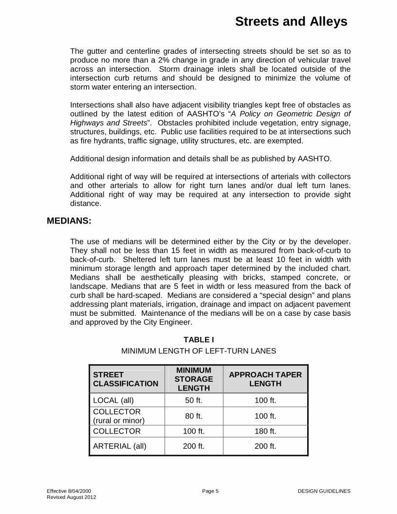
MEDIANS: The use of medians will be determined either by the City or by the developer. They shall not be less than 15 feet in width as measured from back-of-curb to back-of-curb. Sheltered left turn lanes must be at least 10 feet in width with minimum storage length and approach taper determined by the included chart. Medians shall be aesthetically pleasing with bricks, stamped concrete, or landscape. Medians that are 5 feet in width or less measured from the back of curb shall be hard-scaped. Medians are considered a “special design” and plans addressing plant materials, irrigation, drainage and impact on adjacent pavement must be submitted. Maintenance of the medians will be on a case by case basis and approved by the City Engineer.
TABLE I
MINIMUM LENGTH OF LEFT-TURN LANES
STREET CLASSIFICATION
MINIMUMSTORAGE LENGTH
APPROACH TAPER LENGTH
LOCAL (all) 50 ft. 100 ft.
COLLECTOR (rural or minor)
80 ft. 100 ft.
COLLECTOR 100 ft. 180 ft.
ARTERIAL (all) 200 ft. 200 ft.

Streets and Alleys
Effective 8/04/2000 Page 6 DESIGN GUIDELINES Revised August 2012
Optimally, median openings will be spaced, at a minimum, every 1000 feet. The City can approve additional median openings, but in no case should an opening be closer than 500 feet to another opening or to a street intersection. All median openings shall require a left turn lane. Additional design information and details shall be as published by AASHTO.
FLARED SECTIONS (“Elbows”, “Knuckels”, “Eyebrows”):
Note that the Cities do not require the use of flared sections in residential subdivisions even if the streets do not have a ninety degree bend. The flared sections are actually discouraged as they often cause maintenance issues. Islands will be considered as “special designs” and will be reviewed on a case by case basis. A homeowner’s association is required to provide maintenance of landscaping and improvements contained in islands. If an island is proposed in a culdesac or flared section, the developer is responsible to design and install no parking signage for the roadway around the island. No parking is necessary to ensure adequate access for sanitation trucks and emergency vehicles.
SIDEWALKS:
Sidewalks shall be a minimum of 5 feet in width (located 3 feet from the back of curb) on local streets. Sidewalks located along streets classified as minor collector and larger shall be a minimum of 6 feet in width (located 3 feet from the back of curb) or 8 feet in width when located adjacent to the back of curb. In existing street areas where this is not possible the City will work with the developer on a width compatible with existing conditions. When approved by the City, sidewalk alignments may be varied to accommodate landscaping and avoid trees or other obstructions in the standard sidewalk location. In all circumstances, a minimum clear pedestrian width of 4 feet shall be provided. Designs for the construction of sidewalks shall meet current TAS and ADA standards. Concrete driveways, regardless of length or slope, will contain a minimum 5 foot wide sidewalk section with a cross slope as shown on the standard detail which aligns with sidewalk approaches. In instances where drainage passes underneath a sidewalk and cannot be accommodated otherwise, steel plates shall be used, ¾” thick, diamond shaped surface, and bolted down. Design shall be approved by the City Engineer.

Streets and Alleys
Effective 8/04/2000 Page 7 DESIGN GUIDELINES Revised August 2012
PAVEMENT STRUCTURE:
Pavement structure for urban streets is generally determined by the anticipated loads to be carried, the quality and strength of the paving materials used and the load bearing capacity of the underlying subgrade. This manual provides minimum criteria for both rigid and flexible pavements using generalized soil conditions applicable to coarse grained and clay soils for each street classification. These minimum criteria are shown in Table VIII. The design engineer shall visit the site and make soil tests to determine the appropriate subgrade preparation and pavement design. If an alternate pavement design is proposed, the engineer should discuss with the City such alternate ideas and methodology. The engineer shall base the pavement thickness designs on actual soil analyses and use the current AASHTO pavement thickness design methods. Specific pavement thickness designs submitted for approval must be accompanied by soils testing reports to fully support the assumptions of the procedure being used. Parameters based on general soil classifications will not be permitted. The City reserves the right to deny alternate designs. When underground utility conduits or storm sewers are constructed or reconstructed in open trenches beneath new pavement, the trenches must be backfilled over the required bedding and compacted up to the bottom of the subgrade as shown in the City’s Standard Construction Details.
CURBING:
Rural streets are not required to have curbs. All other streets shall have 6-inch raised curb. Residential streets may have a standard lay-down curb. All lay-down curb designs must be accompanied with drainage design calculations. Sidewalks shall not be installed adjacent to lay-down curb.
Curbing for rigid pavements shall conform to the cross sections as shown in the City’s Standard Construction Details and shall be poured monolithically with the paving or be doweled in.
STREET CROWNS:
Street crowns shall be at the centerline of pavement and will be set by a straight 3% cross-slope upward from the edge of the gutter. Offset crowns may be used in unusual circumstances. No streets, with the exception of alleys, will be allowed to have center drains.

Streets and Alleys
Effective 8/04/2000 Page 8 DESIGN GUIDELINES Revised August 2012
ETJ STREETS:
Concrete streets are not allowed in developments in the ETJ.
Utilities parallel to the roadway in ETJ developments shall not be located within rights of way.
ENTRANCE ISLANDS:
Entrance islands will be considered as "special designs" and will be reviewed on a case by case basis. A homeowners association is required to provide maintenance of landscaping and improvements contained in entrance islands.
SIGNAGE:
Regulatory Signage:
All regulatory signage shall be in compliance with the TMUTCD. In College Station, the Developer shall install at least three ‘End of Road’ signs (OM4-1) per TMUTCD standards using TxDOT’s sign foundation “Wedge Anchor System”.
Street Name Signs
In the City of College Station only, street name signs will be installed by the Developer. Developer must submit a dimensioned location plan and the street name signs for both public and private streets shall be designed and installed according to the City’s standards. This sign standard can be acquired by contacting the City’s Traffic Division. The Developer shall contact the City of College Station’s Planning and Development Services to acquire the required block number for the signs. The City of Bryan will continue to install signs with city forces. A fee for sign installation, in the City of Bryan only, shall be paid at the time that the final plat is ready for filing.
Decorative Signage
Special sign poles are allowed but the installation must meet State safety requirements.
Other Signs
All other signs will be regulated by the sign ordinance.
Foundations City of Bryan shall require the “Wedge Anchor System” on all signs. City of College Station shall require, as shown on TxDOT standard details, the “Triangular Slipbase System” on collectors and above and the “Wedge Anchor System” on local streets.

Streets and Alleys
Effective 8/04/2000 Page 9 DESIGN GUIDELINES Revised August 2012
TABLE II PAVEMENT MARKINGS AND SIGNAGE
PAVEMENT
MARKINGS (INCLUDING BIKE
LANES)
STREET NAME SIGNS
ALL OTHER SIGNAGE
PLANS
Developer provides plans for all streets
and facilities to TMUTCD standards
(In College Station)Developer produces
dimensional location plan
Developer provides plans for all streets and
facilities to TMUTCD standards
INSTALLED
Developer installs all pavement markings
and markers.
(In College Station)Developer installs street name signs.
Letter of Completion and
opening held until all signs are
installed.
(In Bryan) City to install all
street name signs. Letter of
Occupancy to be held until street
name sign fee has been received
(In College Station) All signs must meet the TMUTCD and are to be
installed by the developer, except for
regulatory signs. Additionally, the
developer shall be responsible for installing ‘End of Road’ markers according to TMUTCD
standards.
(In Bryan) All signs, except street
name signs, are installed by the Developer unless
otherwise specified.
PAVEMENT MARKINGS:
Construction Plans shall note that all pavement markings shall meet the latest version of the TxDOT Standard Specifications Item 666 for Type I markings. Crosswalks
Crosswalk markings are important traffic control devices at controlled intersections. These devices identify the appropriate location for pedestrians to cross the intersection as well as informing drivers where pedestrians maybe present. Not all locations need the crosswalks marked; however, typically collector and arterial streets do. As stated in the TMUTCD, an engineering study should be performed before crosswalks are installed at locations other than controlled intersections.

Streets and Alleys
Effective 8/04/2000 Page 10 DESIGN GUIDELINES Revised August 2012
The City of Bryan’s preference for marking crosswalks is the longitudinal style (or “Ladder” style). The City of College Station’s preference is the typical “Transverse” style; however, in the Northgate area, adjacent to school or school zones, and other high pedestrian crossings, the longitudinal style (or “Ladder” style) is preferred. Deviation from these preferences will be allowed only with the approval of the City Engineer.
The longitudinal style markings shall be 24” wide and 8 feet in length, spaced 48-inches apart.
The transverse markings shall consist of two 12-inch wide lines separated by 6 feet of unmarked pavement. All crosswalk pavement markings shall always meet TxDOT’s specification for Type I markings unless otherwise approved by the City Engineer.
Additional information about crosswalk markings can be found in the TMUTCD.
The design of crosswalks with brick pavers, stamped asphalt, stamped concrete, etc., shall also accommodate in that design the placement of retroreflective, thermoplastic transverse or longitudinal style striping for crosswalks.
Stop and Yield Lines
Unless otherwise specified, all stop and yield lines shall meet TxDOT’s specification for Type I markings The design of crosswalks with brick pavers, stamped concrete, etc. shall also accommodated in that design the placement of retroreflective stop lines and/or yield lines.
STREETSCAPE:
Handrails
The design shown in the Standard Sidewalk Details will be used wherever a vertical drop of 8 inches or greater within 3 feet of the walkway exists.
Street Furniture
Street furniture will be in accordance with the standards adopted in the overlay district, where one exists.
Brick Pavers
Brick pavers may be used on sidewalks and on streets at crosswalks or in intersections. Brick pavers in streets and sidewalks are to be placed on top of full depth concrete pavement. The color and texture of brick pavers
Streets and Alleys
Effective 8/04/2000 Page 11 DESIGN GUIDELINES Revised August 2012
will be in accordance with the standards adopted in the overlay district, where one exists. Retroreflective thermoplastic transverse striping is required on either side of brick paver crosswalks.
Brick pavers shall be used on medians less than 4 feet in width or within 50 feet of median noses. Brick pavers in medians will be installed on top of a sand bed or base material instead of full depth pavement.
Patterned Colored Concrete
Patterned colored concrete may be used on sidewalks, crosswalks, in intersections, or in medians. Color should be integral to the concrete or by stain.
GATED NEIGHBORHOODS:
No gates are allowed on public streets. A homeowners association is required for maintenance of gates. Access shall be provided for emergency services, utility and solid waste services and for pedestrians.
STREETLIGHTS:
Street lighting will be included in all new developments. The pole lamp and fixture specifications as well as the cost for street light installation will be per local codes. Street lights should be placed at all intersections, at the end of all cul-de-sacs and at a spacing of 300 feet. Spacing within rural areas may be larger with approval of the City Engineer.
BICYCLE FACILITIES:
All bicycle facilities, including but not limited to, bike routes, bike lanes, and bike paths shall be designed in accordance with the most current AASHTO guidelines.

Streets and Alleys
Effective 8/04/2000 Page 12 DESIGN GUIDELINES Revised August 2012
TABLE III - MINIMUM GEOMETRIC DESIGN CRITERIA FOR NEW CONSTRUCTION
Alley Residential NTD
Residential Streets1
Rural4 Residential
Rural4 Collector
MinorCollector/
CommercialStreet
Major Collector
Minor Arterial
Undivided
Minor Arterial Divided
Major Arterial
ROW2 24’ 50’ 50’ 70’ 100’ 60’7 80’ 100’ 100’ 120’
Pavement Width3
12’ 27’ 24’ 24’ 30’ 38’ 54’ 70’ 72’ or 78’ 96’
Traffic Lanes
N/A 2 2 2 2 2 or 3 3 or 4 5 4 6
Lane Width5 N/A N/A N/A 12’ 15’ 12’ 12’ or
12’/15’5 12.5’/15’5 12.5’/15 or 12.5’/12’5
12.5’/12’/ 15’5
Curb None Laydown or standard Laydown or standard None6 None Standard Standard Standard Standard Standard Shoulder Width
N/A N/A N/A 2 @ 3’ Ea6 2 @ 3’ Ea6 N/A N/A N/A N/A N/A
Left Turn Lane Width
None None None None None Permitted
(14’) Permitted
(16’) Permitted
(15’) None None
Parking None Permitted One Side
Only None None
Permitted w/out bike
lanes None None None None
Raised Medians
None None None None None None None None 17’ 17’
Sidewalks Req./Width
None Per local Subdivision
Ordinance/ 5’ Per local Subdivision
Ordinance/ 5’ None None Both/ 6’ 8 Both/ 6’ 8 Both/ 6’ 8 Both/ 6’ 8 Both/ 6’ 8
Bike Lanes N/A N/A N/A N/A N/A Permitted per bicycle
plan
Permitted per bicycle
plan N/A
Permitted per bicycle
plan N/A
NOTES: Cul-de-sacs on residential and rural streets, including streets in the ETJ, shall have a 50’ ROW radius with a 40’ pavement radius. All other cul-de-sac streets shall have a min.
60’ ROW radius with a min. 50’ pavement radius. Temp. T turnarounds, in accordance with the local fire code, will only be allowed under circumstances when no other option is viable and with prior approval.
At all intersecting street rights-of-ways, provide a minimum 25’ ROW chamfer. Additional easements may be required parallel to the street right-of-way for utilities if necessary.
1 No more than 24 lots between cross streets. Allowed in single family developments only. 2 Right of Way widths listed herein are a minimum and additional right of way may be required for the City of Bryan. Right-of-Way widths for the City of College Station are provided
in Table V. At intersections of collector to collector streets or greater, additional row will be provided for dual left or right turn lanes as required by traffic impact study or requested by the City.
3 Pavement widths are measured from back of curb to back of curb or from the edge of pavement to edge of pavement where there is no curb. 4 Rural sections shall only be used where allowed by local zoning. Rural collector streets will not be required to have 16’ easements parallel to right-of-way within ETJ limits and will
not be allowed within city limits. 5 Wider lanes required on outside lanes only. 6 Rural Residential Shoulders shall be asphalt primed or shall have ribbon curb installed. Ribbon curb applies only to those rural sections located within the city limits. 7 A 5 foot easement will be required on either side of right-of-way. 8 Sidewalk may be 8 feet in width when located adjacent to the back of curb.

Streets and Alleys
Effective 8/04/2000 Page 13 DESIGN GUIDELINES Revised August 2012
TABLE IV
CITY OF COLLEGE STATION REQUIRED RIGHT-OF-WAY
Roadway Classification**
Context
Class** Right-of-Way
Width (ft)* Alley n/a 24
Local Suburban
Estate/Rural
50
70
Minor Collector
(Commercial Street)
Mixed Use Urban Urban General Suburban Restricted Suburban Estate/Rural
85 85 77 77
100
Major Collector 2-Lane
Mixed Use Urban Urban General Suburban Restricted Suburban Estate/Rural
100 100 77 77
100
Major Collector 4-Lane
Mixed Use Urban Urban General Suburban Restricted Suburban Estate/Rural
125 125 115 115 115
Minor Arterial 4-Lane
Mixed Use Urban Urban General Suburban Restricted Suburban Estate/Rural
125 125 115 115 115
Major Arterial 4-Lane
Mixed Use Urban Urban General Suburban Restricted Suburban Estate/Rural
128 128 118 118 112
Major Arterial 6-Lane
Mixed Use Urban Urban General Suburban Restricted Suburban Estate/Rural
150 150 140 140 165
* (Note: Table IV provides the ROW requirements for the City of Bryan.) At intersections of collector to collector streets or greater, additional right-of-way will be provided for dual left or right turn lanes as required by traffic impact study or requested by the City
** Roadway Classification and Context Class is determined by the City of College Station’s most current Thorough Fare Plan.

Streets and Alleys
Effective 8/04/2000 Page 14 DESIGN GUIDELINES Revised August 2012
TABLE V
STREET CLASSIFICATION DEFINITIONS
ALLEY: A minor public right-of-way which provides a secondary means of vehicular access to abutting property and which is used primarily for vehicular traffic to the rear or side of properties which otherwise abut on a public street. Parking is not allowed on alleys.
COMMERCIAL STREET: A street which primarily serves commercial or multi-family development. Commercial streets shall be built to at least Minor Collector standards.
MAJOR ARTERIAL STREET: A street which carries high volumes of vehicular traffic (in the general range of 20,000 VP to 60,000 VP) and which is intended to move traffic in, out or around the City.
MINOR ARTERIAL STREET: A street which carries high volumes of vehicular traffic (in the general range of 5,000 VP to 30,000 VP) and which is intended to move traffic around the City.
MAJOR COLLECTOR STREET: A street which primarily serves vehicular traffic (in the general range of 5,000 to 10,000 VP) from residential streets and minor collectors to arterials. A collector may also provide very limited access to abutting properties if approved by the City.
MINOR COLLECTOR STREET: A street which primarily serves vehicular traffic (in the general range of 1,000 to 5,000 VP) from residential streets to collectors or arterials. A minor collector may also provide limited access to abutting properties if approved by the City. Additionally, the streets identified as collectors on the Thoroughfare Plan may be designed as minor collectors only if approved by the City.
NEO-TRADITIONAL DESIGN (NTD) RESIDENTIAL STREET: A street which primarily serves vehicular traffic to abutting single family residential properties where narrow, more curvilinear streets are desired. Parking is only allowed on one side of the street and block length is limited.
RESIDENTIAL STREET: A street which primarily serves vehicular traffic to abutting residential properties. A residential may also provide limited access to commercial properties if approved by the City.
RURAL RESIDENTIAL STREET: A street in the ETJ of the City which primarily serves vehicular traffic to abutting residential properties. A rural residential may also provide limited access to commercial properties if approved at the time of platting by the City and County. Construction and maintenance of the rural residential streets are generally under the jurisdiction of the County. Rural street sections are allowed inside the city limits in areas with appropriate zoning and lot size. Refer to the local zoning ordinance for guidance.
RURAL COLLECTOR STREET: A street in the ETJ of the City which primarily serves vehicular traffic from residential streets to arterials. A rural collector may provide limited access to abutting residential properties if approved at the time of platting by the City and County. Construction and maintenance of the rural collectors are generally under the jurisdiction of the County.

Streets and Alleys
Effective 8/04/2000 Page 15 DESIGN GUIDELINES Revised August 2012
TABLE VI
MINIMUM GEOMETRIC CRITERIA FOR STOPPING SIGHT DISTANCE
STREET CLASSIFICATION
DESIGN VEHICLE
DESIGN SPEED (mph)
STOPPING SIGHT
DISTANCE (ft)
MIN. “K” 1
CREST SAG
MINOR COLLECTOR SU 35 250 29 49
RURAL COLLECTOR & MAJOR COLLECTOR
SU 40 305 44 64
MINOR ARTERIAL WB-50 45 360 61 79
MAJOR ARTERIAL WB-50 By Design By Design By Design By Design
1 If intersecting grades result in a “K” value less than that shown, the minimum vertical curve length shall be equal to 3xDesign Speed. NOTES:
Sight distance at street intersections shall be provided in accordance with the latest edition of AASHTO’s “A Policy on Geometric Design of Highways and Streets” measured 10’ from the edge of the intersecting street.

Streets and Alleys
Effective 8/04/2000 Page 16 DESIGN GUIDELINES Revised August 2012
TABLE VII MINIMUM GEOMETRIC CRITERIA FOR HORIZONTAL CURVATURE
Street Classification
Design Vehicle
Design Speed (mph)
Des. Max. Rate of Super-
elevation (%)
Min. Center-
line Radius (ft)
Max Tangent Between Reverse Curves
Min. Tangent Between Reverse
Curves (ft)
Max. Relative Edge Slopes
for Super Transition 1
(ft/ft)
Rural Collector Minor Collector Major Collector
SU SU SU
40 35 40
N/A N/A N/A
575 430 575
N/A N/A N/A
By Design By Design By Design
N/A N/A N/A
Minor Arterial Major Arterial
WB-50 WB-50
45 By Design
6 6
675 By Design
N/A N/A
By Design By Design
1:200 1:225
1 Super-elevation transition is to be accomplished 2/3 outside of the horizontal curve and 1/3 within the curve. The minimum tangent between successive horizontal curves should be designed such that proper super-elevation transitions can be effected.
Example for calculating super-elevation and minimum tangent between successive curves: Given: 5-lane minor arterial with 12-foot lanes and a 14-foot TWLTL. Typical section is rooftop crown with 2% cross slopes. 675-foot curve left followed by a 675-foot curve right. Super-elevation rotation is about center of road. 6% maximum super-elevation required for the minimum curves given.
High side max. relative vertical transition = (0.06-(-0.02)) x (12'+12'+ (14'/2)) = 2.48 feet
Horizontal transition required to effect super-elevation = 2.48' x 200 (from last column in above table) = 496 feet
2/3 within tangent = 330 feet; 1/3 within curve = 166 feet Low side max. relative vertical transition = (0.06 - 0.02) x (12'+12'+ (14'/2)) = 1.24 feet
Horizontal transition required to effect super-elevation = 1.24' x 200 (from last column in above table) = 248 feet
2/3 within tangent = 165 feet; 1/3 within curve = 83 feet Therefore, the minimum tangent length required between these two curves is 495 feet, or 330 feet + 165 feet.
Streets and Alleys
Effective 8/04/2000 Page 17 DESIGN GUIDELINES Revised August 2012
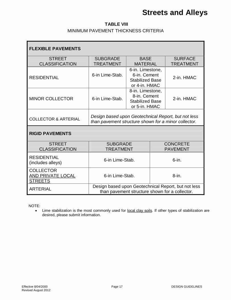
TABLE VIII
MINIMUM PAVEMENT THICKNESS CRITERIA
FLEXIBLE PAVEMENTS
STREET CLASSIFICATION
SUBGRADE TREATMENT
BASE MATERIAL
SURFACE TREATMENT
RESIDENTIAL 6-in Lime-Stab.
6-in. Limestone, 6-in. Cement
Stabilized Base or 4-in. HMAC
2-in. HMAC
MINOR COLLECTOR 6-in Lime-Stab.
8-in. Limestone, 8-in. Cement
Stabilized Base or 5-in. HMAC
2-in. HMAC
COLLECTOR & ARTERIAL Design based upon Geotechnical Report, but not less than pavement structure shown for a minor collector.
RIGID PAVEMENTS
STREET CLASSIFICATION
SUBGRADE TREATMENT
CONCRETE PAVEMENT
RESIDENTIAL (includes alleys)
6-in Lime-Stab. 6-in.
COLLECTOR AND PRIVATE LOCAL STREETS
6-in Lime-Stab. 8-in.
ARTERIAL Design based upon Geotechnical Report, but not less
than pavement structure shown for a collector.
NOTE: Lime stabilization is the most commonly used for local clay soils. If other types of stabilization are
desired, please submit information.

Streets and Alleys
Effective 8/04/2000 Page 18 DESIGN GUIDELINES Revised August 2012
FIGURE 1 RESIDENTIAL STREET SECTIONS

Streets and Alleys
Effective 8/04/2000 Page 18 DESIGN GUIDELINES Revised June 2012
FIGURE 2
COLLECTOR STREET SECTIONS
* Right-of-Way widths for the City of College Station are provided in Table V – City of College Station Required Right-Of-Way. Width of areas
from the curb to the limit of the right-of-way in College Station, likewise, varies from above figure accordingly.

Streets and Alleys
Effective 8/04/2000 Page 20 DESIGN GUIDELINES Revised August 2012
FIGURE 3
ARTERIAL STREET SECTIONS
* Right-of-Way widths for the City of College Station are provided in Table V – City of College Station Required Right-Of-Way. Width of areas from the curb to the limit of the right-of-way in College Station, likewise, varies from above figure accordingly.

Streets and Alleys
Effective 8/04/2000 Page 21 DESIGN GUIDELINES Revised August 2012
FIGURE 4
SINGLE UNIT TURNING DESIGN TEMPLATE

Streets and Alleys
Effective 8/04/2000 Page 22 DESIGN GUIDELINES Revised August 2012
FIGURE 5
WB-50 TURNING DESIGN TEMPLATE

Streets and Alleys
Effective 8/04/2000 Page 23 DESIGN GUIDELINES Revised August 2012
FIGURE 6
PASSENGER CAR TURNING DESIGN TEMPLATE

Streets and Alleys
Effective 8/04/2000 Page 24 DESIGN GUIDELINES Revised August 2012
FIGURE 7
FIRE LADDER TRUCK TURNING DESIGN TEMPLATE

Streets and Alleys
Effective 8/04/2000 Page 25 DESIGN GUIDELINES Revised August 2012
FIGURE 8
CLEARANCE DIMENSIONS FOR COMPOSITE VEHICLES