street lighting design manual - index - city of … lighting design and installation requirements...
TRANSCRIPT
CORPORATION OF THE CITY OF BURLINGTON
SPECIFICATIONS
INDEX FOR
STREET LIGHTING DESIGN MANUAL
(SPEC NO. SS8)

December 2015
INDEX
1 Street Lighting Design and Installation Requirements - General .............................. 3 1.1 Glossary ............................................................................................................... 3 1.2 General ................................................................................................................. 4 1.3 Replacement and Upgrade Policy ......................................................................... 4 1.4 Downtown Lighting Policy ..................................................................................... 4
2 Design Criteria ............................................................................................................... 6
2.1 Maximum Recommended Spacings for Street Lights on the City of Burlington’s Standard Sections: ............................................................................................... 8
2.2 Maximum Recommended Spacings for Decorative HPS & LED Street Luminaires on the City of Burlington’s Standard Sections ................................... 10
2.3 Lighting For Urban Intersections ......................................................................... 12 2.4 ESA Lighting Design Requirements .................................................................... 13 2.5 Curves and Hills ................................................................................................. 13 2.6 Culs-de-sac ........................................................................................................ 13 2.6.1 Lighting in Culs-de-sac ....................................................................................... 13
3 Material Specifications ................................................................................................ 15
3.1 Street Light Poles ............................................................................................... 15 3.2 Cobra Head HPS Luminaire/Pole/Bracket Combination ...................................... 15 3.3 “LED” Luminaire/Pole/ Bracket Combinations ..................................................... 16 3.4 Decorative Luminaire/Pole/ Bracket Combinations ............................................. 17 3.5 Standard Round Concrete Street Light Poles ..................................................... 19 3.6 Decorative Black Concrete Street Light Poles ..................................................... 19 3.7 Decorative Aluminium Poles ............................................................................... 20 3.8 Luminaires .......................................................................................................... 20 3.8.1 Cobra Head HPS Luminaires .............................................................................. 20 3.8.2 LED Luminaires .................................................................................................. 22 3.8.3 Decorative LED Luminaires ................................................................................ 22 3.9 Brackets ............................................................................................................. 23 3.10 Photo-Electric Controllers ................................................................................... 23 3.11 Lamps ................................................................................................................. 23 3.12 Loadcentres ........................................................................................................ 24 3.13 Street Light Cable Duct ....................................................................................... 24 3.14 Street Light Wiring from the Handhole to the Luminaire ...................................... 24 3.15 Street Light Distribution Cable from Loadcentre to Street Light Poles (Load-side Circuits) 24 3.16 Street Light Power Supply Cable from Transformer to Loadcentre (Line-side Circuits) .... 24 3.17 Grounding Rods and Plates ................................................................................ 24
4 Installation Specifications ........................................................................................... 25 5 Installation Specifications ........................................................................................... 25
5.1 General ............................................................................................................... 26 5.2 Cable .................................................................................................................. 26 5.3 Street Light Cable Duct ....................................................................................... 27 5.4 Poles .................................................................................................................. 27
December 2015
5.5 Lumenaires, Brackets and Photo Controllers ...................................................... 27
APPENDIX A: SPILL LIGHT APPENDIX B: LED SPECIFICATIONS APPENDIX C: US. DOE SPECIFICATIONS

December 2015
1
Street Lighting Design and Installation Requirements
1.1
Glossary:
ANSI/IESNA RP-8-14 - Illuminating Engineering Society of North America's American National Standard Practice for Roadway Lighting, issued June 26, 2014.
Luminance Design – a design based on the amount of light which is reflected from a surface and reaches the eye of the observer. It is based on the “light” the observer sees at a given point and is based on the reflectance of the surface and the angle and distance of the observer from the point observed. See RP-8-14, Annex A for further information on luminance.
Illuminance Design - a design based on the amount of light which incident on a surface. Illuminance ignores the surface upon which the light falls. See RP- 8-14, Annex A4 for further information on illuminance.
Pedestrian Conflict Area Classification – Road classifications describe general conditions of vehicular traffic conflict in urban areas. A second type of conflict is the vehicular/pedestrian interaction. Pedestrian activity is nearly always related to the adjacent land uses. There are three levels of pedestrian conflict used by RP-8-14, high, medium and low. For the purposes of this manual, the pedestrian conflict level is assumed to be low for rural and low density urban areas. Medium for high density developments and adjacent to schools. Downtown locations are considered to be high density. High PC Areas are areas with significant numbers of pedestrians on the sidewalks or crossing the streets during darkness. Examples are downtown retail areas, areas near theatres, concert halls stadiums and transit terminals.
Medium PC Areas are areas where fewer pedestrians use the streets at night. Examples are downtown office areas, areas with libraries, apartments, neighbourhood shopping and streets with transit lines. Low PC Areas are areas with low volumes of pedestrian traffic at night. Examples are suburban streets, low density developments and rural or semi-rural areas.
See RP-8-14 for further information on pedestrian conflict classifications.
Pavement Classifications – Luminance calculations require information about the directional surface reflectance of the pavement. There are four general pavement classifications given in RP-8-14;
R1, which is concrete or old asphalt pavement, R2, which is asphalt with a relatively high level of gravel or light coloured aggregate,
R3, which is asphalt with a normal aggregate mix and normal age and wear – this is the typical road classification for roads and the pavement classification to be used in Burlington unless otherwise directed by the City, R4, which is asphalt with very smooth texture that is mostly specular.

December 2015
1.2
General:
Street lighting design in the City of Burlington shall be generally based on ANSI/IESNA RP-8-14. Street lighting design in Burlington must provide uniform lighting at a level that is adequate and comfortable for vehicular and pedestrian movement on the City’s roads and sidewalks. All street lighting systems in the City of Burlington shall be designed by a qualified lighting designer using the luminance method as described in RP-8-14 (unless noted otherwise), as well as incorporating both the City’s and Burlington Hydro’s standards and specifications as given below. Street lighting design in Burlington must take into consideration all of the approved luminaires of a given type in order to allow interchangeability of luminaires during maintenance operations.
Recommended maximum spacing or arrangements given in the following sections are to be used for the specific cross section or road layout shown. Variations in cross section, road layout and/or pedestrian conflict levels must be dealt with on an individual design basis, with a specific lighting design and associated calculations submitted to the City for review.
It is the responsibility of the street lighting designer to ensure they have the latest revisions of the City of Burlington’s street lighting standards and specifications and a current list of approved suppliers prior to designing a street lighting system. As of January 1, 2003, all street lighting design and construction is subject to Electrical Safety Authority (ESA) inspection and approval. All materials used for street lighting in the City of Burlington must meet CSA specifications. Street lighting luminaires to be installed on Burlington Hydro poles shall have Ontario Regulation 22/04 documents and drawings prepared and submitted to Hydro for approval. Decorative street lighting may be used in the City only with the City’s permission and in accordance with the City’s requirements and specifications.
1.3
Replacement and Upgrade Policy:
New installations shall be designed and constructed in accordance with the specifications contained in this manual wherever possible. Where the designer wishes to use materials or specifications not contained in this manual, they must first contact the City to obtain their approval.
It is the policy of the City that damaged or destroyed street light poles, luminaires, etc. shall be replaced with materials in accordance with the new standards. 1.4
Downtown Lighting Policy:
The downtown area of the City is considered unique and requires special consideration. There is in general a high level of pedestrian activity in the downtown area, particularly during the numerous special events that occur in the summer months. In view of this, the
December 2015
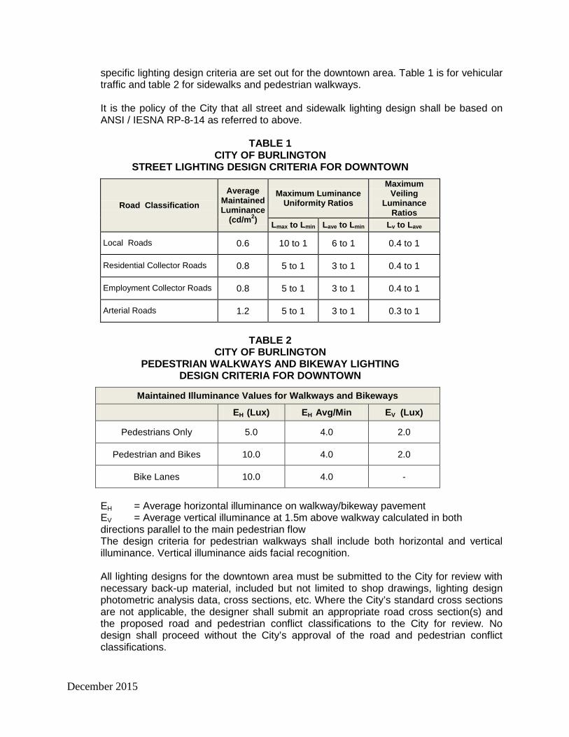
specific lighting design criteria are set out for the downtown area. Table 1 is for vehicular traffic and table 2 for sidewalks and pedestrian walkways. It is the policy of the City that all street and sidewalk lighting design shall be based on ANSI / IESNA RP-8-14 as referred to above.
TABLE 1 CITY OF BURLINGTON
STREET LIGHTING DESIGN CRITERIA FOR DOWNTOWN
Road Classification Average
Maintained Luminance
(cd/m2)
Maximum Luminance Uniformity Ratios
Maximum Veiling
Luminance Ratios
Lmax to Lmin Lave to Lmin Lv to Lave Local Roads 0.6 10 to 1 6 to 1 0.4 to 1
Residential Collector Roads 0.8 5 to 1 3 to 1 0.4 to 1
Employment Collector Roads 0.8 5 to 1 3 to 1 0.4 to 1
Arterial Roads 1.2 5 to 1 3 to 1 0.3 to 1
TABLE 2
CITY OF BURLINGTON PEDESTRIAN WALKWAYS AND BIKEWAY LIGHTING
DESIGN CRITERIA FOR DOWNTOWN
Maintained Illuminance Values for Walkways and Bikeways
EH (Lux) EH Avg/Min EV (Lux)
Pedestrians Only 5.0 4.0 2.0
Pedestrian and Bikes 10.0 4.0 2.0
Bike Lanes 10.0 4.0 -
EH = Average horizontal illuminance on walkway/bikeway pavement EV = Average vertical illuminance at 1.5m above walkway calculated in both directions parallel to the main pedestrian flow The design criteria for pedestrian walkways shall include both horizontal and vertical illuminance. Vertical illuminance aids facial recognition. All lighting designs for the downtown area must be submitted to the City for review with necessary back-up material, included but not limited to shop drawings, lighting design photometric analysis data, cross sections, etc. Where the City’s standard cross sections are not applicable, the designer shall submit an appropriate road cross section(s) and the proposed road and pedestrian conflict classifications to the City for review. No design shall proceed without the City’s approval of the road and pedestrian conflict classifications.
December 2015
2
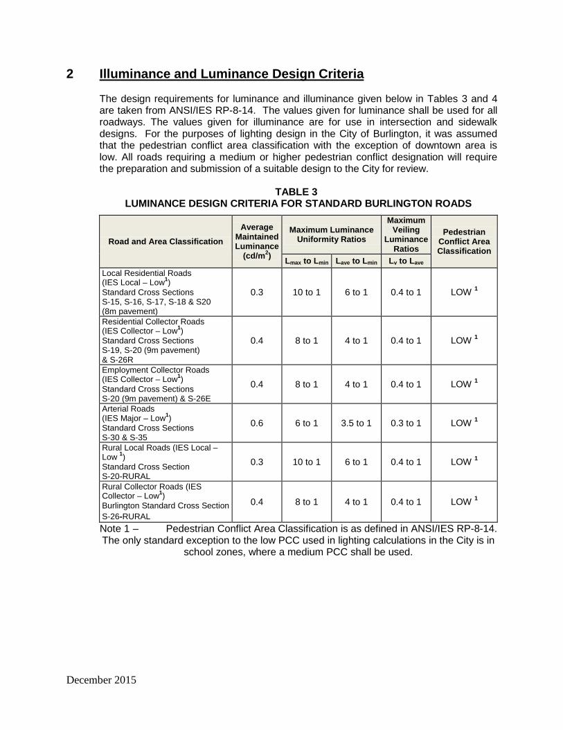
Illuminance and Luminance Design Criteria
The design requirements for luminance and illuminance given below in Tables 3 and 4 are taken from ANSI/IES RP-8-14. The values given for luminance shall be used for all roadways. The values given for illuminance are for use in intersection and sidewalk designs. For the purposes of lighting design in the City of Burlington, it was assumed that the pedestrian conflict area classification with the exception of downtown area is low. All roads requiring a medium or higher pedestrian conflict designation will require the preparation and submission of a suitable design to the City for review.
TABLE 3
LUMINANCE DESIGN CRITERIA FOR STANDARD BURLINGTON ROADS
Road and Area Classification Average
Maintained Luminance
(cd/m2)
Maximum Luminance Uniformity Ratios
Maximum Veiling
Luminance Ratios
Pedestrian Conflict Area Classification
Lmax to Lmin Lave to Lmin Lv to Lave Local Residential Roads (IES Local – Low1) Standard Cross Sections S-15, S-16, S-17, S-18 & S20 (8m pavement)
0.3 10 to 1 6 to 1 0.4 to 1 LOW 1
Residential Collector Roads (IES Collector – Low1) Standard Cross Sections S-19, S-20 (9m pavement) & S-26R
0.4 8 to 1 4 to 1 0.4 to 1 LOW 1
Employment Collector Roads (IES Collector – Low1) Standard Cross Sections S-20 (9m pavement) & S-26E
0.4 8 to 1 4 to 1 0.4 to 1 LOW 1
Arterial Roads (IES Major – Low1) Standard Cross Sections S-30 & S-35
0.6 6 to 1 3.5 to 1 0.3 to 1 LOW 1
Rural Local Roads (IES Local – Low 1) Standard Cross Section S-20-RURAL
0.3 10 to 1 6 to 1 0.4 to 1 LOW 1
Rural Collector Roads (IES Collector – Low1) Burlington Standard Cross Section S-26-RURAL
0.4 8 to 1 4 to 1 0.4 to 1 LOW 1
Note 1 – Pedestrian Conflict Area Classification is as defined in ANSI/IES RP-8-14. The only standard exception to the low PCC used in lighting calculations in the City is in
school zones, where a medium PCC shall be used.

December 2015
TABLE 4 ILLUMINANCE DESIGN CRITERIA FOR INTERSECTIONS
AND CUL-DE-SACS
Intersection Classification
Minimum Average Maintained Illuminance
(horizontal only 3) (R2 & R3 Pavements
2) Eave in lux
Maximum Illuminance
Uniformity Ratio Eave to Emin
Local Road/Local Road Standard Cross Sections: S-15, S-17, S-18 & S-20 (8m pavement)
8 6.0
Residential Collector Roads / Collector Road Standard Cross Sections: S-19, S-20 & (9m pavement) & S-26R
8 4.0
Employment Collector Roads / Collector Road Standard Cross Section: S-26E & S-20 (9m pavement)
12 4.0
Arterial Roads / Collector Standard Cross Sections: S-30 & S-35 15 3.0
Arterial / Arterial Standard Cross Sections S30 & S36 18 3.0
Rural Local Roads /Local Standard Cross Section S-20-RURAL 8 6.0
Cul-de-Sacs 4 8
Note 1 – Pedestrian Conflict Area Classification is as defined in ANSI/IES RP-8-14. Note 2 – Pavement Classification is as defined in ANSI/IES RP-8-14.
TABLE 5 ILLUMINANCE DESIGN CRITERIA FOR PEDESTRIAN WALKWAYS
AND SIDEWALKS
Minimum Average Maintained Illuminance
(horizontal only ) Eave in lux
Maximum Illuminance
Uniformity Ratio Eave to Emin
Minimum Vertical Illuminance
EV (Min) lux
Rural 2.0 10.0 0.6
Low Density Residential 3.0 6.0 0.8
Medium Density Residential 4.0 4.0 1.0
The above noted values are for low pedestrian conflict areas. High pedestrian conflict areas are covered in the Downtown section. Pedestrian illumination shall include both horizontal and vertical illuminance.

December 2015
2.1
Maximum Recommended Spacings for Street Lighting on the City of Burlington’s Standard Sections
Using the luminaire/pole combinations listed in Tables 6 & 7, the tables below gives the maximum allowable spacings for flat glass HPS and LED luminaires for straight sections, gradual curves and gently sloping grades for single sided, two sided staggered and two sided opposite arrangements.
The spacings given below are to be used for the design of street lighting on residential streets having the same dimensions for the essential items of the road cross section indicated, i.e., pavement width, luminaire offset and sidewalk width and offset. Variations in any of these essential items, such as pavement width in or near intersections, must be dealt with on an individual design basis and a specific lighting design with its associated calculations submitted to the City for review and approval. The Light Loss Factor (LLF) used for the spacings in Table 6 (HPS) is 0.77 and Table 7 (LED) is 0.85.
TABLE 6 MAXIMUM RECOMMENDED SPACINGS ON STRAIGHT SECTIONS FOR
FLAT GLASS “COBRA-HEAD” LUMINAIRES WITH HPS LAMPS
Luminaire Wattage
Type of R.O.W. Burlington Standard Cross Section
Number Single Sided
Spacing Two Sided Spacing;
Staggered
Two Sided Spacing; Opposite
100 watt HPS
15 m Minor Local Residential - Standard S-15 43 m 43 m
Not Recommended
100 watt HPS
17 m Minor Local Residential - Standard S-17 43 m 43 m
Not Recommended
100 watt HPS
18 m Local Residential - Standard S-18
42 m 42 m Not
Recommended
100 watt HPS
20 m Local Residential - Standard S-20 (8m pavement)
41 m 41 m Not
Recommended
100 watt HPS
20 m Rural Local Residential - Standard S-20-RURAL1,7 54 m 54 m
Not Recommended
100 watt HPS
20 m Rural Local Residential – Standard S-20-RURAL (with Hydro pole line) 1,4,7
53 m 53 m Not
Recommended
150 watt HPS
19 m Residential Collector - Standard S-19 41 m 48 m
Not Recommended
150 watt HPS
20 m Residential Collector – Standard S-20 (9m pavement) 41 m 48 m
Not Recommended
150 watt HPS
26 m Residential Collector - Standard S-26R
Not Recommended 40 m 59 m
150 watt HPS
20 m Industrial Collector - Standard S-20 (9m pavement with Hydro pole line 2)
41 m 48 m Not
Recommended

December 2015
Luminaire Wattage
Type of R.O.W. Burlington Standard Cross Section
Number Single Sided
Spacing Two Sided Spacing;
Staggered
Two Sided Spacing; Opposite
150 watt HPS
26 m Employment Collector - Standard S-26E
Not Recommended 37 m 59 m
150 watt HPS
26 m Employment Collector - Standard S-26E (with Hydro pole line) 3
Not Recommended
Not Recommended 59 m
150 watt HPS
26 m Rural Collector - Standard S-26-RURAL (with Hydro pole line) 4,6,8
60 m 58 m Not
Recommended
200 watt HPS
30 m Arterial Road - Standard S-30 (4-lane pavement; 1.5 m sidewalks)
Not Recommended 46 m 70 m
200 watt HPS
30 m Arterial Road - Burlington Standard S-30 (4-lane pavement; with Hydro pole line) 5
Not Recommended
Not Recommended 67 m
200 watt HPS
35 m Arterial Road - Standard S-35 (4-lane pavement)
Not Recommended 40 m 76 m
200 watt HPS
35 m Arterial Road - Standard S-35 (5-lane pavement)
Not Recommended 37 m 74 m
200 watt HPS
35 m Arterial Road - Standard S-35 (4-lane pavement; with Hydro pole line) 5
Not Recommended
Not Recommended 67 m
200 watt HPS
35 m Arterial Road - Standard S-35 (5-lane pavement; with Hydro pole line) 5
Not Recommended
Not Recommended 62 m
TABLE 7 MAXIMUM RECOMMENDED SPACINGS ON STRAIGHT SECTIONS FOR “LED” LUMINAIRES
Manufacturer Watts Type of ROW Single Sided
Two Sided
Staggered
Two Sided
Opposite
Sidewalk Horizontal
Sidewalk Vertical
GE 454651 67 15 m Local Road - Standard S-15 60 N/R N/R 4.5-3.5 2.2
Cooper NVN-AC-03-E-V- 53 15 m Local Road -
Standard S-15 58 N/R N/R 3.5-3.2 1.8
Cree XSPC HT 03 53 15 m Local Road -
Standard S-15 60 N/R N/R 3.6 – 3.5 2.1
LED Roadway NXT24S 700 2HB
54 15 m Local Road - Standard S-15 59 N/R N/R 6.0 – 1.7 1.1
GE 454651 67 17m Local Road S-17 59 112 N/R 4.5 – 1.8 1.5
Cooper NVN-AC-01-E-V- 53 17m Local Road
S-17 58 112 N/R 3.6 – 3.4 1.3
Cree XSPC HT03 50 17m Local Road
S-17 60 116 N/R 4.8 – 5.6 2.5
LED Roadway NXT24S7002HB 54 17m Local Road
S-17 54 116 N/R 6.9 – 1.9 2.5

December 2015
Manufacturer Watts Type of ROW Single Sided
Two Sided
Staggered
Two Sided
Opposite
Sidewalk Horizontal
Sidewalk Vertical
GE 454651 67 18m Local Road S-18 59 116 N/R 4.5 – 1.8 1.1
Cree XSPC HT 50 18m Local Road S-18 60 110 N/R 4.8 – 5.62 1.9
Cooper NVN-A-01-E-V- 53 18m Local Road
S-18 60 102 N/R 2.0 1.0
LED Roadway NXT24S7002HB 54 18m Local Road
S-18 59 115 N/R 6.0- 1.7 1.1
GE 454651 67 19m Local Road S-19 60 120 N/R 1.52 0.75
Cree XSPC HT3 50 19m Local Road S-19 60 110 N/R 1.7 1.0
Cooper NVN-AC-03 53 19m Local Road
S-19 60 102 N/R 1.6 0.9
LER Roadway NXT24S700 2HB 54 19m Local Road
S-19 60 116 N/R 1.2 0.9
GE 454651 67 20m Local Road S-20 66 125 N/R 4.0 - 1.6 0.7
Cree XSP C HT3 50 20m Local Road S-20 70 125 N/R 4.3 1.1
Cooper NVN-AC-3 53 20m Local Road
S-20 60 110 N/R 1.4 0.75
LED Roadway NXT24S 700 2HB
54 20m Local Road S-20 58 N/R 5.5 2.1
Cooper XNV2 2 3 76 19m residential
collector S-19 54 102 NR 2.9 0.8
Cree XSP B3ME 50 19m residential collector S-19 55 108 NR 3.6 1.8
Cree XSPCHT23ME 97
26m rural collector with hydro pole
S 26 44 N/A N/A 5.4 1.9
Cooper X NV2 2 3 76
26m rural collector with hydro pole
S 26 53 N/A N/A 8.7 2.6
Cree XSPC HE-2MEU 139 30m urban arterial
S 30 NC 67 68 4.2 1.9
Cooper XNV2-AC-XX3 110 30m urban arterial
S 30 NC 66 66 6.3 3.8
Cree XSP-3MEE 139 35m urban arterial S35 NR 67 66 4.1 1.9
Cooper XNV-223 110 35m urban arterial S35 NR 66 64 6.2 3.6
Note: N/R = not recommended N/A = not applicable For roadway sections with sidewalks on both sides, two sided staggered or opposite layout is recommended.
2.2
Maximum Recommended Spacings for Decorative HPS & LED Street Luminaires on the City of Burlington’s Standard Sections:
Using the decorative luminaire/pole combinations listed in Tables 8 & 9, the tables below gives the maximum allowable spacings for decorative street lights for straight sections,

December 2015
gradual curves and gently sloping grades for single sided and two sided, staggered arrangements.
TABLE 8
MAXIMUM RECOMMENDED SPACINGS ON STRAIGHT SECTIONS FOR DECORATIVE “HPS” LUMINAIRES
Luminaire Wattage
Type of R.O.W. Burlington Standard Cross Section
Number Single Sided
Spacing Two Sided Spacing;
Staggered
Two Sided Spacing; Opposite
100 watt HPS
15 m Minor Local Residential - Standard S-15 37 m 39 m Not Recommended
100 watt HPS
17 m Minor Local Residential - Standard S-17 37 m 39 m Not Recommended
100 watt HPS
18 m Local Residential - Standard S-18 30 m 39 m Not Recommended
100 watt HPS
20 m Local Residential - Standard S-20 (8m pavement)
Not Recommended 39 m Not Recommended
100 watt HPS
20 m Rural Local Residential - Standard S-20-RURAL 1,4 42 m 44 m Not Recommended
150 watt HPS
19 m Residential Collector – Standard S-19 38 m 52 m 60 m
150 watt HPS
20 m Residential Collector - Standard S-20 (9m pavement) 37 m 52 m 60 m
150 watt HPS
26 m Residential Collector – Standard S-26R
Not Recommended 38 m 51 m
150 watt HPS
26 m Employment Collector - Standard S-26E
Not Recommended 41 m 52 m
150 watt HPS
26 m Employment Collector - Standard S-26E (with Hydro pole line) 2, 3
Not Recommended
Not Recommended 64 m
150 watt HPS
26 m Rural Collector - Standard S-26-RURAL 4,5 43 m 44 m Not Recommended
N/A 30 m Arterial Road - Standard S-30
Not Recommended
Not Recommended Not Recommended
N/A 35 m Arterial Road - Standard S-35
Not Recommended
Not Recommended Not Recommended
TABLE 9 MAXIMUM RECOMMENDED SPACINGS ON STRAIGHT SECTIONS
FOR DECORATIVE “LED” LUMINAIRES
Manufacturer Watts Type of ROW Single sided
Two sided staggered
Two sided opposite
Cooper SDLB02LEDTTSL2 51 15 m Local Residential -
Standard S-15 45 Not Recommended
Not Recommended
King K601S P FAFL III
60 SSL 120 55 15 m Local Residential -
Standard S-15 47 Not Recommended
Not Recommended

December 2015
Manufacturer Watts Type of ROW Single sided
Two sided staggered
Two sided opposite
Sternberg 1843LED 4ARC45T3CTA 66 15 m Local Residential -
Standard S-15 42 Not Recommended
Not Recommended
Cooper SDLB02LEDTTSL2 51 17m local residential
road S-17 45 Not Recommended
Not Recommended
King K601S P FAFL III
60 SSL 120 55 17m local residential
road S-17 47 90 Not Recommended
Sternberg 1843LED
4ARC45T3CTA 66 17m local residential
road S-17 42 85 Not Recommended
Cooper SDLB02LEDTTSL2 51 18m local residential
road S-18 45 Not Recommended
Not Recommended
King K601S P FAFL III
60 SSL 120 55 18m local residential
road S-18 47 90 Not Recommended
Sternberg 1843LED 4ARC45T3CTA 66 18m local residential
road S-18 43 85 Not Recommended
Cooper SDLB02LEDTTSL2 51 19m local residential
road S-19 45 95 Not Recommended
King K601S P FAFL III
60 SSL 120 55 19m local residential
road S-19 47 90 Not Recommended
Sternberg 1843LED 4ARC45T3CTA 66 19m local residential
road S-19 43 85 Not Recommended
Cooper SDLB02LEDTTSL2 51 20m local residential
road S-20 44 70 Not Recommended
KingmCG439P 77 20m local residential road S-20 52 76 73
KingmCG439P 77 19m residential collector S-19 38 73 70
Sternberg 1843LED 4ARC45T3CTA 66 19m residential collector
S-19 50 76 Not Recommended
Cooper SDLB02LEDTTSL2 49 19m residential collector
S-19 40 66 Not Recommended
Sternberg 1843LED 4ARC45T3CTA 153
26m rural collector with hydro pole S 26
36 Not Recommended
Not Recommended
Cooper SDLB02LEDTTSL2 153
26m rural collector with hydro pole S 26
31 N/A N/A
2.3
Lighting for Urban Intersections
The luminance method is difficult to use with the design of lighting for intersections, due to the basic assumptions inherent in luminance design and the methods used in its calculation. Therefore illuminance criteria and calculations are recommended for use in the design of intersections. Intersections should be illuminated to a level equal to the sum of the recommended average illumination levels for each of the intersecting roads. These levels are given in Table 4, above. A pedestrian conflict classification of “low” is included in the illumination levels given in table 4. No further adjustment of lighting levels
December 2015
is required due to pedestrian conflict classifications unless a higher classification is required.
2.4
ESA Lighting Design Requirements
The new ESA regulations came into effect as of January 1, 2003. These regulations are intended to separate the street lighting system from the electrical distribution system and to allow parties other than the local distribution company to maintain street lights. In order to accomplish this, a lighting designer must place a service entrance rated disconnect between the electrical distribution system and the street lighting system. The method approved by the City of Burlington at this time is to run an appropriately sized service cable to a street light pedestal (see City of Burlington Dwg. No. S-156) and from there to the individual street lighting circuits. A maximum of a 5% voltage drop will be allowed in the street lighting cable from the transformer to the last light in the circuit. All materials, including the secondary service to the disconnect switch, must be CSA approved and will be subject to ESA inspection and approval.
2.5
Curves and Hills
Tables 6 and 7, Maximum Spacing on Straight Sections for the two types of luminaire/pole combinations, are to be used on relatively straight and level sections only. When lighting curves and/or hills, the spacings in the aforementioned tables should be modified in accordance with the procedures given in ANSI/IES RP-8-14 in Section 5.8.
2.6
Cul-de-Sacs
There are several design criteria to be addressed when designing lighting for the end (bulb) of cul-de-sacs. These are: • The area to be lit is not readily adaptable to the standard luminaires used in
Burlington; • The space available for the placement of the luminaires/poles is generally quite
limited due to the convergence of driveways in the boulevard areas; and • Due to the basic assumptions inherent in luminance design and the methods used in
its calculation, the use of luminance criteria at the ends of cul-de-sac (or any other “dead-end” arrangement) is not recommended. Illuminance criteria and calculations are recommended for use in the design of cul-de-sac, as specified in Table 4.
2.6.1
Lighting in Cul-de-Sacs
It is suggested that lighting in cul-de-sacs be arranged in accordance with the sketches given below.
December 2015
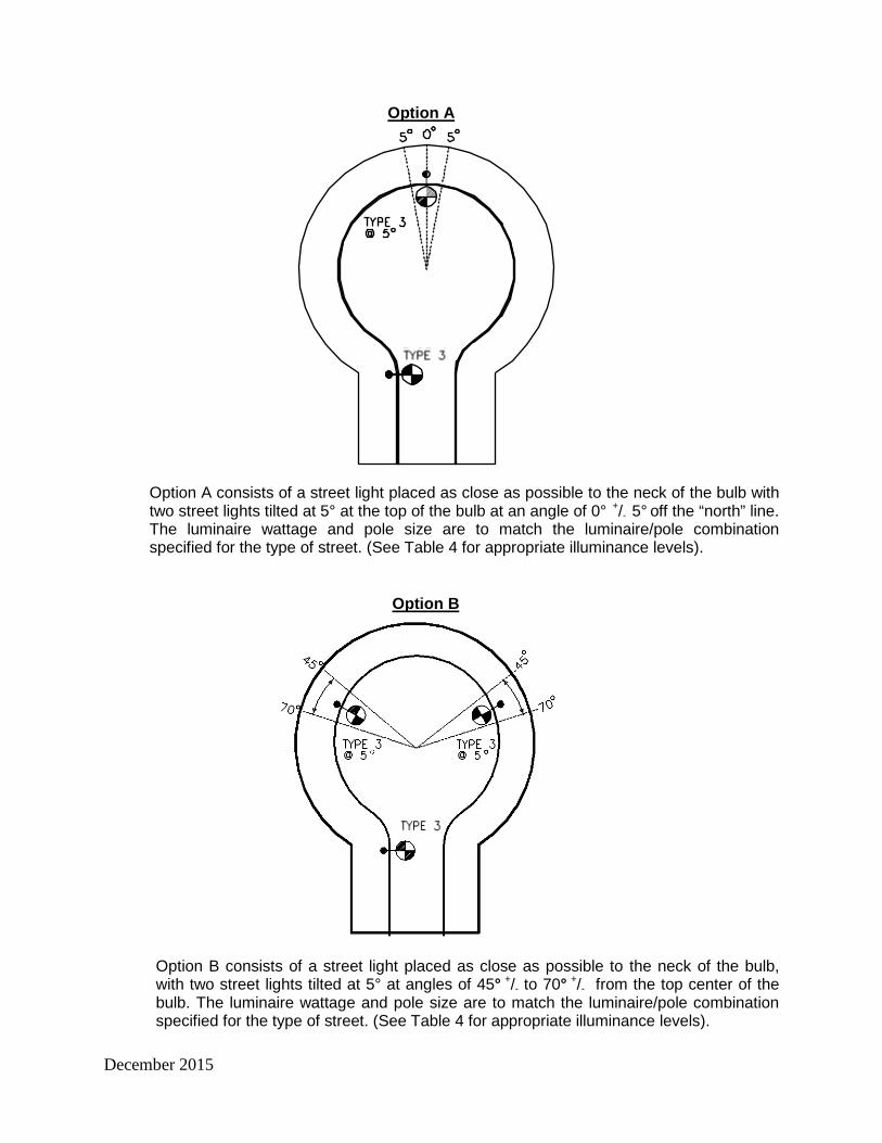
Option A
Option A consists of a street light placed as close as possible to the neck of the bulb with two street lights tilted at 5° at the top of the bulb at an angle of 0° +/- 5° off the “north” line. The luminaire wattage and pole size are to match the luminaire/pole combination specified for the type of street. (See Table 4 for appropriate illuminance levels).
Option B
Option B consists of a street light placed as close as possible to the neck of the bulb, with two street lights tilted at 5° at angles of 45° +/- to 70° +/- from the top center of the bulb. The luminaire wattage and pole size are to match the luminaire/pole combination specified for the type of street. (See Table 4 for appropriate illuminance levels).

December 2015
Designs for street lights using arrangements other than the standard locations given above shall be accompanied by a full set of lighting calculations for review and approval by the City.
3
Material Specifications
All street lighting equipment used in the City of Burlington must meet the current City of Burlington’s street lighting standards and specifications. It is the responsibility of the street lighting designer to ensure they have the latest revisions of the City’s street lighting specifications and list of approved suppliers prior to ordering any materials. All street lighting components are to be manufactured in strict accordance with the City’s current requirements.
3.1
Street Light Poles
Street light poles used in the City of Burlington must be manufactured in accordance with the City’s street light pole specifications as given below.
3.2
“Cobra Head” HPS Luminaire/Pole/ Bracket Combinations
In general, the following “cobra head” luminaire/pole combinations with HPS lamps shall to be used in the City of Burlington.
TABLE 9 “COBRA HEAD” HPS LUMINAIRE/POLE/BRACKET COMBINATIONS
Road Type Luminaire Standard Pole Pole Finish Bracket 15m Minor Local Residential - Standard S-15 100 Watt 9.45 m round
concrete pole mold finish 1.8 m
17m Minor Local Residential - Standard S-17 100 Watt 9.45 m round
concrete pole mold finish 1.8 m 18m Local Residential - Standard S-18 100 Watt 9.45 m round
concrete pole mold finish 1.8 m
20m Local Residential - Standard S-20 (8m pavement)
100 Watt 9.45 m round concrete pole mold finish 1.8 m
20m Rural Local - Standard S-20- RURAL
100 Watt (single source) 1
10.7 m round concrete pole mold finish 2.4 m
20m Rural Local - Standard S-20- RURAL
100 Watt (single source) 1 Hydro pole N/A 1.8 m (2.1 m rise)
mounted at 7.8 m 19m Residential Collector - Standard S-19 150 Watt 9.45 m round
concrete pole mold finish 1.8 m
20m Residential Collector – Standard S-20 (9m pavement)
150 Watt 9.45 m round concrete pole mold finish 1.8 m
26m Residential Collector - Standard S-26R 150 Watt 9.9 m round
concrete pole mold finish 2.4 m
December 2015
Road Type Luminaire Standard Pole Pole Finish Bracket
20m Industrial Collector - Standard S-20 (9m pavement)
150 Watt Hydro pole N/A
1.8 m (2.1 m rise) mounted at 6.4 m
ORmounted at 7.6 m
1.8 m
26m Employment Collector - Standard S-26E 150 Watt Hydro pole N/A
1.8 m (2.1 m rise) mounted at 7.1 m
ORmounted at 8.0 m
2.4 m
26m Employment Collector - Standard S-26E 150 Watt 9.9 m round
concrete pole mold finish 2.4 m
26m Rural Collector – Standard S-26 – RURAL
150 Watt (single source) 2
10.7 m round concrete pole mold finish 2.4 m
26m Rural Collector – Standard S-26 – RURAL
150 Watt (single source) 2 Hydro pole N/A 1.8 m (2.1 m rise)
mounted at 7.8 m 30m Arterial Road - Standard S-30 200 Watt 11.4 m round
concrete pole mold finish 2.4 m
30m Arterial Road - Standard S-30 200 Watt Hydro pole N/A 1.8 m (2.1 m rise)
mounted at 7.6 m 35m Arterial Road - Standard S-35 200 Watt 11.4 m round
concrete pole mold finish 2.4m
35m Arterial Road - Standard S-35 200 Watt Hydro pole N/A 1.8 m (2.1 m rise)
mounted at 7.6 m
Note 1 – Cooper OVH – type 3 luminaire only (curve #OVH10S3D.IES) Note 2 – Cooper OVF – type 3 luminaire only (curve #767456.IES)
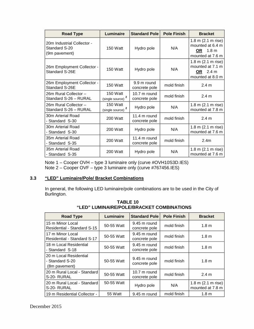
3.3
“LED” Luminaire/Pole/ Bracket Combinations
In general, the following LED luminaire/pole combinations are to be used in the City of Burlington.
TABLE 10 “LED” LUMINAIRE/POLE/BRACKET COMBINATIONS
Road Type Luminaire Standard Pole Pole Finish Bracket 15 m Minor Local Residential - Standard S-15 50-55 Watt 9.45 m round
concrete pole mold finish 1.8 m
17 m Minor Local Residential - Standard S-17 50-55 Watt 9.45 m round
concrete pole mold finish 1.8 m
18 m Local Residential - Standard S-18 50-55 Watt 9.45 m round
concrete pole mold finish 1.8 m
20 m Local Residential - Standard S-20 (8m pavement)
50-55 Watt 9.45 m round concrete pole mold finish 1.8 m
20 m Rural Local - Standard S-20- RURAL 50-55 Watt 10.7 m round
concrete pole mold finish 2.4 m
20 m Rural Local - Standard S-20- RURAL
50-55 Watt Hydro pole N/A 1.8 m (2.1 m rise)
mounted at 7.8 m 19 m Residential Collector - 55 Watt 9.45 m round mold finish 1.8 m

December 2015
Road Type Luminaire Standard Pole Pole Finish Bracket Standard S-19 concrete pole 20 m Residential Collector – Standard S-20 (9m pavement)
55 Watt 9.45 m round concrete pole mold finish 1.8 m
26 m Residential Collector - Standard S-26R 65 Watt 9.9 m round
concrete pole mold finish 2.4 m
20 m Industrial Collector - Standard S-20 (9m pavement)
65 Watt Hydro pole N/A
1.8 m (2.1 m rise) mounted at 6.4 m
ORmounted at 7.6 m
1.8 m
26 m Employment Collector - Standard S-26E 65 Watt Hydro pole N/A
1.8 m (2.1 m rise) mounted at 7.1 m
ORmounted at 8.0 m
2.4 m
26 m Employment Collector - Standard S-26E 100 Watt 9.9 m round
concrete pole mold finish 2.4 m
26 m Rural Collector – Standard S-26 – RURAL
100 Watt
10.7 m round concrete pole mold finish 2.4 m
26 m Rural Collector – Standard S-26 – RURAL
100 Watt Hydro pole N/A 1.8 m (2.1 m rise)
mounted at 7.8 m 30 m Arterial Road - Standard S-30 100-150 Watt 11.4 m round
concrete pole mold finish 2.4 m
30 m Arterial Road - Standard S-30 100-150 Watt Hydro pole N/A 1.8 m (2.1 m rise)
mounted at 7.6 m 35 m Arterial Road - Standard S-35 100-150 Watt 11.4 m round
concrete pole mold finish 2.4m
35 m Arterial Road - Standard S-35 100-150 Watt Hydro pole N/A 1.8 m (2.1 m rise)
mounted at 7.6 m 3.4
Decorative Luminaire/Pole/ Bracket Combinations
In general, the following decorative luminaire/pole combinations are to be used in the City of Burlington.
TABLE 11 DECORATIVE HPS LUMINAIRE/POLE/BRACKET COMBINATIONS
Road Type Luminaire Standard Pole Pole Finish Bracket 15 m Minor Local Residential – Standard S-15
100 Watt 9.9 m octagonal concrete pole
Polished black eclipse 1.5 m
17 m Minor Local Residential – Standard S-17
100 Watt 9.9 m octagonal concrete pole
Polished black eclipse 1.5 m
18 m Local Residential - Standard S-18 100 Watt 9.9 m octagonal
concrete pole Polished
black eclipse 1.5 m
20 m Local Residential - Standard S-20 (8m pavement)
100 Watt 9.9 m octagonal concrete pole
Polished black eclipse 1.5 m

December 2015
Road Type Luminaire Standard Pole Pole Finish Bracket 20 m Rural Local Residential – Standard S-20 - RURAL
100 Watt 10.7 m octagonal concrete pole
Polished black eclipse 1.8 m
19 m Residential Collector – Standard S-19 150 Watt 9.9 m octagonal
concrete pole Polished
black eclipse 1.8 m 20 m Residential Collector - Standard S-20 150 Watt 9.9 m octagonal
concrete pole Polished
black eclipse 1.8 m 26 m Residential Collector - Standard S-26R 150 Watt 10.7 m octagonal
concrete pole Polished
black eclipse 1.8 m 26 m Employment Collector - Standard S-26E 150 Watt 10.7 m octagonal
concrete pole Polished
black eclipse 1.8 m
26 m Employment Collector - Standard S-26E
150 Watt (standard
cobrahead) Hydro pole N/A 1.8 m (2.1 m rise)
mounted at 7.1 m 26 m Rural Collector – Standard S-26 – RURAL 150 Watt 10.7 m octagonal
concrete pole Polished
black eclipse 1.8 m
When ordering street light poles to the City of Burlington’s standards, the appropriate City Street Light Specification Numbers, BSL-01-01 (latest revision), for the pole, the bracket and the luminaire must
be specified together.
TABLE 12
DECORATIVE LED LUMINAIRE/POLE/BRACKET COMBINATIONS
Road Type Luminaire Standard Pole Pole Finish Bracket 15 m Minor Local Residential – Standard S-15
51-66 Watt
9.9 m octagonal concrete pole
Polished black eclipse 1.5 m
17 m Minor Local Residential – Standard S-17
51-66
Watt 9.9 m octagonal concrete pole
Polished black eclipse 1.5 m
18 m Local Residential - Standard S-18
51-66 Watt
9.9 m octagonal concrete pole
Polished black eclipse 1.5 m
20 m Local Residential - Standard S-20 (8m pavement)
51-66 Watt
9.9 m octagonal concrete pole
Polished black eclipse 1.5 m
20 m Rural Local Residential – Standard S-20 - RURAL
51-66 Watt
10.7 m octagonal concrete pole
Polished black eclipse 1.8 m
19 m Residential Collector – Standard S-19
51-66 Watt
9.9 m octagonal concrete pole
Polished black eclipse 1.8 m
20 m Residential Collector - Standard S-20 90 Watt 9.9 m octagonal
concrete pole Polished
black eclipse 1.8 m 26 m Residential Collector - Standard S-26R 90 Watt 10.7 m octagonal
concrete pole Polished
black eclipse 1.8 m
When ordering street light poles to the City of Burlington’s standards, the appropriate City Street Light Specification Numbers, BSL-01-01 (latest revision), for the pole, the bracket and the luminaire must
be specified together.

December 2015
3.5
Standard Round Concrete Street Light Poles
9.45 metre (31.0 ft.) Class B Centrifugally Cast Round Concrete Pole The 9.45 metre concrete street light pole shall be a direct buried Class B pre-stressed round concrete pole with provision for electrical ground, natural concrete finish and suitable for use with a 1.8 metre tapered aluminum bracket and manufactured in accordance with the City of Burlington Street Light Specification Number BSL-01-01, (latest revision). Approved suppliers and their catalogue numbers for this pole are given in Table 7 of Material Specification SS08B. 9.9 metre (32.5 ft) Class B Centrifugally Cast Round Concrete Pole The 9.9 metre concrete street light pole shall be a direct buried Class B pre-stressed round concrete pole with provision for electrical ground, natural concrete finish and suitable for use with a 2.4 metre tapered aluminum bracket and manufactured in accordance with the City of Burlington Street Light Specification Number BSL-01-02, (latest revision). Approved suppliers and their catalogue numbers for this pole are given in Table 7 of Material Specification SS08B.
10.7 metre (35.0 ft) Class B Centrifugally Cast Round Concrete Pole The 10.7 metre concrete street light pole shall be a direct buried Class B pre-stressed round concrete pole with provision for electrical ground, natural concrete finish and suitable for use with a 2.4 metre tapered aluminum bracket and manufactured in accordance with the City of Burlington Street Light Specification Number BSL-01-03, (latest revision). Approved suppliers and their catalogue numbers for this pole are given in Table 7 of Material Specification SS08B.
11.4 metre (37.5 ft) Class B Centrifugally Cast Round Concrete Pole The 11.4 metre concrete street light pole shall be a direct buried Class B pre-stressed round concrete pole with provision for electrical ground, natural concrete finish and suitable for use with a 2.4 metre tapered aluminum bracket and manufactured in accordance with the City of Burlington Street Light Specification Number BSL-01-04, (latest revision). Approved suppliers and their catalogue numbers for this pole are given in Table 7 of Material Specification SS08B.
3.6
Decorative Black Concrete Street Light Poles
9.9 metre (32.5 ft) Class B Centrifugally Cast Black Octagonal Tapered Concrete Pole The 9.9 metre black octagonal tapered concrete street light pole shall be a direct buried Class B pre-stressed concrete pole with provision for electrical ground, black eclipse polished finish a side mount decorative bracket and luminaire, manufactured in accordance with the City of Burlington Street Light Specification Number BSL-01-11, (latest revision). Approved suppliers and their catalogue numbers for this pole are given in Table 7 of Material Specification SS08B.
10.7 metre (35.0 ft) Class B Centrifugally Cast Black Octagonal Tapered Concrete Pole The 10.7 metre black octagonal tapered concrete street light pole shall be a direct buried Class B pre-stressed concrete pole with provision for electrical ground, black eclipse polished finish a side mount decorative bracket and luminaire, manufactured in accordance with the City of Burlington Street Light Specification Number BSL-01-12,

December 2015
(latest revision). Approved suppliers and their catalogue numbers for this pole are given in Table 7 of Material Specification SS08B.
3.7
Decorative Aluminum Poles
Decorative Aluminium Poles: (Downtown locations)
The 5m tall decorative poles shall be Aluminium, one piece construction. The 500mm fluted cast aluminium base shall be constructed with a 150-100 mm dia tapered aluminium shaft. The pole shall be UL/CSA approved.
The base shall be designed with 12 curved flutes and teardrop decorations and be made of heavy wall 356 grade alloy cast aluminium. The base shall have a 25mm thick floor cast as an integral part of the base. The shaft shall be double circumferentially welded internally and externally. The shaft shall be tapered fluted extruded and be made of ASTM 6063 extruded aluminium and tempered to T6 condition. The pole shall be provided with four 20mm dia galvanized “L” type anchor bolts. Each anchor bolt shall be equipped with double nuts. A door shall be provided for wiring and anchor bolt access. It shall be secured with tamper proof stainless steel hardware. A ground lug shall be installed in the pole handhole. The shaft and base shall be powder coated “Old World Grey”.
Options
• GFI Receptacle • Flag pole holder • Single banner arm • Double banner arm • Planter arm • Wreath mount hooks
3.8
Luminaires
All luminaires used in the City of Burlington must be manufactured in accordance with the City of Burlington’s luminaire specifications as given below (latest revision). All luminaires shall come complete with a bird stop.
3.8.1
“COBRA HEAD” HPS Luminaires
Photometric Requirements As a minimum, the photometric performance of the luminaires for conventional lighting shall be according to CSA C653. Photometric test results shall be provided for the luminaires supplied and shall include the following data: a) Isolux curves and mounting height correction factors. b) Utilization charts or graphs. c) Intensity distribution curves indicating peak intensity.

December 2015
d) Luminous intensity tables to Illuminating Engineering Society format (I-tables). e) Luminaire efficiency values. f) Luminous outputs above and below horizontal. g) Lamp lumen outputs and wattages.
Electrical Requirements
• All electrical components and assembled luminaires shall be according to CSA C22.2 No. 9.0 or shall be ULC approved.
• Ballasts, lamp sockets, ground connectors, internal wiring, and all other components shall be suitable for the supply voltage as specified in the Contract Documents and the maximum temperature encountered in totally enclosed outdoor weatherproof luminaires.
• Ballasts shall be auto-transformer or isolated secondary transformer type for grounded systems. Auto-transformer type ballasts shall have a maximum tolerance of 12% variation in lamp wattage for a 5% variation in line voltage. Isolated secondary transformer type ballasts shall have a maximum of 12% variation in lamp wattage for a 10% variation in line voltage.
• Ballasts shall be Class H (180 °C) insulation, 60 hertz, and low temperature (-35 °C) with a power factor not less than 0.90.
• The minimum nominal secondary open circuit voltage of ballast for various lamps shall be sufficient to provide reliable starting at -35 °C.
• Ballasts shall be suitable for the lamp’s nominal operating voltage. Terminal blocks shall be held rigidly and shall provide a positive connection for terminating the field wiring.
• The maximum ballast loss for various lamp sizes shall be as shown in Table 13.
Mechanical Requirements
• The luminaire shall be comprised of a cast aluminum ballast housing, spun or formed aluminum optical housing with a glass lens or refractor, and stainless steel hardware.
• The ballast housing shall form a watertight enclosure for the ballast components that shall be readily interchangeable without removing the luminaire from the mounting bracket. The ballast housing shall be either integral or modular design. If it is of modular design, it shall be attached to the housing using stainless steel hardware.
• The mounting arrangements shall consist of a slip fitter assembly for a 50 mm diameter internal pipe size tenon. The slip fitter shall be secured using stainless steel hardware with an independent levelling device. Adjustment of the luminaire in the vertical plane shall be 3 degrees minimum.
• The lamp socket shall be a mogul type with a porcelain-enclosed, nickel-plated brass shell rated for 4,000 volts, and spring-loaded centre contact. The lamp holder shall have an electrically insulated lamp stabilizer and shall hold the lamp's outer envelope to precise alignment with suitable means for vibration damping.
• The optical assembly shall consist of a precision formed specular aluminum reflector with an anodized finish and accurately positioned within the luminaire outer housing. The assembly shall be sealed at the top by a high temperature neoprene or silicone rubber gasket between the ballast casting and reflector and at the bottom by a hinged door assembly.
• Alternatively, the optical assembly shall consist of a pressed borosilicate glass reflector and refractor of open ventilated design. The reflector shall have a smooth non-porous inner surface and be encased within the luminaire outer housing. The

December 2015
refractor shall be attached to the reflector using stainless steel hardware. The reflector or refractor assembly shall be readily removable without removing the luminaire from the mounting bracket.
• The door assembly shall consist of a gasketed doorframe and a clear tempered shock-resistant glass lens and shall be attached to the reflector housing using stainless steel toggle latch
3.8.2
LED Luminaires
The methodology used for shortlisting approved luminaires is that the LED luminaires are ranked on their visual performance with respect to RP-8, the Unit Power Density and the energy saving criteria and then the luminaires that have met these criteria are investigated for their economic performance and shortlisted as shown below.
TABLE 13 Approved LED Luminaires
Manufacturer Cat. No Watts
Arterial Cooper XNV2-Ac-03-X 110
LED Roadway NXT48M 125 CREE X-SP-03MEE 139
Collector 26m ROW
Cooper XNV-2-023-E-U- 76 LED Roadway NXT48M T2 95
Cree X-SPB-03ME-U 97
Collector 19m ROW
GE 454651 67 CREE XSPB03ME 50
LED Roadway NXT-24S-600ma-2HB 49
Local GE 454651 67
Cooper NVN-AC-03-E-V- 53 CREE XBXS C HT03 53
.
3.8.3
Decorative LED Luminaires
The decorative luminaires specified for the City of Burlington have LED arrays positioned horizontally in the luminaires canopy.
TABLE 14 Approved Decorative LED Luminaires
Manufacturer Cat. No Watts
Collector 26m ROW
Cooper SDLB02LEDTTSL2 153
King N/A
Sternberg 1843LED4ARC45T3 153
Collector 19m ROW
Cooper SDLB02LEDTTSL2 51 King K601S P FAFL III 60 SSL 120 55
Sternberg 1843LED 4ARC45T3CTA 66
Local Cooper SDLB02LEDTTSL2 51
King K601S P FAFL III 60 SSL 120 55 Sternberg 1843LED 4ARC45T3CTA 66

December 2015
3.9
Brackets
All street light brackets used in the City of Burlington must be manufactured in accordance with the City of Burlington’s specifications as given below (latest revision).
• Tapered Elliptical Aluminum Brackets
Standard street light brackets for use with "cobra-head" luminaires must be manufactured in accordance with "ANSI C136.1", latest revision.
The brackets shall be a 1.8 m or 2.4 m tapered elliptical aluminum bracket. The brackets for mounting on wooden hydro poles shall be 1.8 m long with 2.1 m rise (“high-rise”) tapered elliptical aluminum brackets. Approved suppliers and their catalogue numbers for the standard brackets are listed in City of Burlington Street Light Specification Numbers BSL-03-01, BSL-03-02 and BSL-03-03.
• Decorative Brackets
Decorative street light brackets must be manufactured in accordance with "ANSI C136.1", latest revision with the changes necessary to apply to arms for decorative fixtures.
The brackets shall be a 1.5 m or a 1.8 m nominal curved bracket with a decorative scroll below the bracket. Approved suppliers and their catalogue numbers for this bracket are listed in City of Burlington Street Light Specification Numbers BSL-03-11 and BSL-03-12.
3.10
Photo-Electric Controllers
Photo-electric controllers for the City of Burlington shall be electronic twist lock photo controllers with: • A filtered (human eye spectral response) silicon light sensor with infrared blocking
filter • MOV surge protection • Rated for 120 volts • Load rating: 1000 watts, 1800vA ballast • Turn on level at 1.5 FC and turn off at 1.5 times turn on • Operating temperature range from -400C to 700C • 20 year life span
Photo-electric controllers must be manufactured using non-hazardous materials.
Approved suppliers and their catalogue numbers for the photo-electrical controllers are listed in the City of Burlington Street Light Specification Number BSL-05-01.
3.11
Lamps
See LED specifications.
December 2015
3.12
Loadcentres
Regarding the ESA Lighting Design Requirements mentioned in section 2.4, above, the City requires the ESA mandated disconnect for any street lighting system. The disconnect is provided by means of a service entrance rated loadcentre (i.e. pedestal type for underground systems, and pole-mounted unit for overhead systems) with weather proof enclosure, and complete with:
• 60 amp, 22 kAIC, 120 V / 240 V double-pole line side main breaker, and 40 amp, 120 V single-pole load side breakers (quantity: up to 6).
Note: Only 120 volt street lighting systems are approved by the City, hence only single pole 120 volt loadside breakers are permitted. Approved suppliers and their catalogue numbers for the materials to be used for the loadcentre and its precast base are listed in the City of Burlington Street Light Specification Numbers BSL-06-01 and BSL-06-11.
3.13
Street Light Cable Duct
Street light cable duct shall be 50 mm (2”) Type II PVC, direct buried duct meeting CAN/CSA-C22.2 NO. 227.1-97 (latest revision).
3.14
Street Light Wiring from the Handhole to the Luminaire
Street light wiring from the handhole to the luminaire shall be 2 - #12 copper NMWU with ground.
3.15
Street Light Distribution Cable from Loadcentre to Street Light Poles (Load-side Circuits)
The street light cable from loadcentre to luminaire and from luminaire to luminaire shall be 3 - #6 copper TWU 600 volt triplexed wires (black/white/green or red/white/green).
3.16
Street Light Power Supply Cable from Transformer to Loadcentre (Line-side Circuits)
The street light supply cable feed from transformer to load center shall be 4 - #2 copper TWU 600 volt (black/red/white/green), as per latest Burlington Hydro standards.
3.17
Grounding Rods and Plates
Ground rods shall be solid steel, 19 mm diameter, 3 m long, copper clad for the full length and shall be according to CSA C22.2 No 41. Ground plates shall present not less than 0.2 m2 of surface to exterior soil and be not less than 6 mm thick as per the Electrical Code. The plates shall be made of hot dip galvanized solid steel. Steel shall be according to CAN/CSA G40.20/G40.21, Grade 230G and shall be galvanized according to CAN/CSA G164.

December 2015
4
Adaptive Lighting
With the development of new lighting technology and effort to reduce the overall energy and environmental impact of lighting, adaptive lighting has become a new trend in the roadway industry. Adaptive lighting is a design methodology in which the light output of a system is adjusted as traffic conditions change. More specifically, roadway lighting illumination levels are adjusted based on the needs of the roadway’s users. The level of lighting can be reduced or dimmed when traffic on roads, sidewalks, or both is reduced. Dimming the lighting level while maintaining the lighting configuration will not affect the uniformity of the lighting or an object’s contrast; however, contrast thresholds will increase, resulting in longer detection times. In addition, luminaires installed in new lighting designs often exceed the requirements of the lighting design. Over time, the system will meet or exceed the design level even as the lamps age and dirt accumulates on lenses. Adjusting the output of luminaires so the system meets the design level throughout the service life of the lamps can also save on energy costs and eliminate periods of over-lighting. This form of lighting control is not specifically considered adaptive lighting, but an adaptive lighting system provides this option. The overall objective of adaptive lighting is to reduce lighting levels on roadways During Periods of Low Traffic Density . Some of the issues to consider are:
• Optimal times and conditions for reducing lighting. • Appropriate lighting levels for various roads and road features. • Appropriate approaches for reducing lighting. • Energy savings and reduction in greenhouse gases that may result from reducing
lighting. • Potential legal issues related to reducing lighting, including the development of such.
The size of the area of the lighting system to be adapted must be considered. Dimming of the roadway system can occur broadly over all the roadways within a given area, or selective dimming of sections of the roadway network can be implemented, based on an analysis of needs. In general, dimming a large area will maintain a constant lighting level throughout the roadway so that drivers will not experience a bright lighting condition on one roadway and then turn onto a dark roadway and be forced to significantly transition their eye adaptation level, which can be uncomfortable and dangerous. However, dimming a large area may also cause some areas to be too dark. It is recommended that each street be evaluated in terms of its lighting needs. However, the difference in lighting classes for streets in a given vicinity should be no greater than two. It is also recommended that residential areas be adapted to a single lighting level. For roadway facilities, each roadway should be assessed individually, but drivers should not experience greater than a two-level change in the lighting class. Transitions on roadways should be a maximum of 1 class per mi of travel
December 2015
5.
Installation Specifications
5.1
General
The contractor shall ensure that the construction and installation of a street lighting system will be completed in a high quality manner and in accordance with the latest revisions of the specifications, standards and drawings of the City of Burlington.
Street lights shall be located on the boulevard in accordance with the City of Burlington’s standard cross sections and as shown on the trenching plans and typical road sections, while maintaining proper clearances from fire hydrants, driveways, transformers, switching units and trees or any other services. The street lighting power supply is to be supplied to each streetlight loadcentre in accordance with Burlington Hydro U/G electrical distribution specs. The entire street light installation is subject to inspection and approval by the ESA. The contractor is responsible for applying and obtaining said inspection. Burlington Hydro will make the connections inside the transformer once the following steps have been fulfilled:
• Approval has been given by the ESA, and a Connection Authorization has been received by Burlington Hydro. City Engineering Inspection will also require a copy of the ESA authorization for the City’s records.
• The contractor has arranged for a Megger testing of the system, and a copy of the successful test report has been submitted to the City Engineering Inspector and the Supervisor of Traffic Operations.
• The Supervisor of Traffic Operations has sent a request for connection letter to Burlington Hydro.
Burlington Hydro shall notify the City Engineering Inspector and the Street light Coordinator once the street light system connection at the transformer has been completed. The City Engineering Inspector shall then energize the streetlight system at the loadcentre and inspect the system operation. Any deficiencies shall be reported by the Inspector to the contractor for rectification.
5.2
Cable
Street light cables shall be installed in conformity with Burlington Hydro’s Underground Electrical Distribution specifications. The cable shall be installed in 50 mm Type II PVC, direct buried duct with a minimum of 600 mm cover. As per the Electrical Code, a 150mm wide red plastic warning tape is to be installed with black lettering stating “ELECTRIC LINE BURIED BELOW”. This warning tape is required to be installed midway between the topmost conductor and final grade above all conductors within the trench.
Where the street light poles are not in place at the time of the cable installation, the end of the cable shall be coiled and staked at the intended pole location in a similar manner to the secondary service cables except that at least 3 m of cable shall be left above grade. Where the cable is to continue on to another street light, the cable shall be looped and not cut, and at least 6 m in total shall be left above grade.

December 2015
Cables are to be inserted into poles via the cable access ports and the ground wire shall be connected to the internal ground lug at the hand hole by means of a #6 AWG compression connector lug.
All connections to ground and to the luminaire conductors are to be made at the hand hole and taped or otherwise insulated after installation.
All connections inside the transformer shall be made by Burlington Hydro.
5.3
Street Light Cable Duct
In general, the ducts shall be placed in accordance with Burlington Hydro’s underground electrical distribution system specifications. In general, the street light duct shall be placed in the common trench on the same level as the secondary and/or communication cables, and on the road side of the trench, with a minimum of 600 mm cover. When street light ducts are placed under driveways, the top 300 mm of the backfill shall be compacted to 100% Standard Proctor Density with granular “A”. Street light duct placed under roadways shall be installed in accordance with City of Burlington Standard Drawing S-150 (latest revision). A ¼” Polypropylene fish rope is to be pulled into each duct.
5.4
Poles
Installation of street light poles is to be in accordance with the City of Burlington Standard Drawings S-153 and S-154 and the manufacturer's requirements.
In general, poles are to be installed in augured or vactored (high pressure water evacuation method) holes to the depths given in the above referenced drawings. The bottom of the hole must be cleaned of loose material before placing the pole.
The Contractor shall take care to ensure that no damage occurs to the electrical or street lighting system or other utilities during the installation of street light poles.
5.5
Luminaires, Brackets and Photo Controllers
Installation of street light luminaires and brackets shall be in accordance with the manufacturer's requirements. In general, luminaires and brackets are to be installed and wired prior to the pole being erected.
The photo-electric controller shall be positioned to face north. The Contractor shall take care to ensure that no damage occurs to the pole, luminaire, bracket or wiring during their assembly and erection.
5.6
Grounding
Two ground rods must be installed adjacent to the street light pedestal, at least 0.3 m below final grade and connected to the bonded neutral block of the service entrance and

December 2015
must be spaced no less than 3 m apart in accordance with the Electrical Code requirements. Alternatively, a ground plate must be installed adjacent to the street light pedestal at least 0.6 m below final grade level and connected to the bonded neutral block of the service entrance. A ground rod/plate shall also be installed at the last street light pole of every circuit and bonded to the pole’s internal ground. Either system is acceptable providing the installation conforms to the Electrical ESA Code requirements.
Page | A-1
APPENDIX A SPILL LIGHT
Lighting Zones
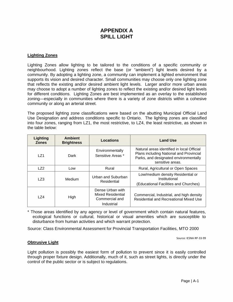
Lighting Zones allow lighting to be tailored to the conditions of a specific community or neighbourhood. Lighting zones reflect the base (or “ambient”) light levels desired by a community. By adopting a lighting zone, a community can implement a lighted environment that supports its vision and desired character. Small communities may choose only one lighting zone that reflects the existing and/or desired ambient light levels. Larger and/or more urban areas may choose to adopt a number of lighting zones to reflect the existing and/or desired light levels for different conditions. Lighting Zones are best implemented as an overlay to the established zoning—especially in communities where there is a variety of zone districts within a cohesive community or along an arterial street. The proposed lighting zone classifications were based on the abutting Municipal Official Land Use Designation and address conditions specific to Ontario. The lighting zones are classified into four zones, ranging from LZ1, the most restrictive, to LZ4, the least restrictive, as shown in the table below:
Lighting Zones
Ambient Brightness Locations Land Use
LZ1 Dark Environmentally Sensitive Areas *
Natural areas identified in local Official Plans including National and Provincial Parks, and designated environmentally
sensitive areas. LZ2 Low Rural Rural, Agricultural or Open Spaces
LZ3 Medium Urban and Suburban Residential
Low/medium density Residential or Institutional
(Educational Facilities and Churches)
LZ4 High
Dense Urban with Mixed Residential Commercial and
Industrial
Commercial, Industrial, and high density Residential and Recreational Mixed Use
* Those areas identified by any agency or level of government which contain natural features, ecological functions or cultural, historical or visual amenities which are susceptible to disturbance from human activities and which warrant protection.
Source: Class Environmental Assessment for Provincial Transportation Facilities, MTO 2000
Source: IESNA RP‐33‐99
Obtrusive Light
Light pollution is possibly the easiest form of pollution to prevent since it is easily controlled through proper fixture design. Additionally, much of it, such as street lights, is directly under the control of the public sector or is subject to regulations.

Page | B-2
Light pollution is defined as excessive and ineffective light, such as light coming from an exposed bulb. Sky glow describes the large scale brightening of the night sky due to the cumulative effect of the illumination of street lights, outdoor advertising, buildings, parking lots, airports, and other sources bouncing off of microscopic particles suspended in the air that is then reflected back to Earth. Sky glow prevents a clear view of the night sky landscape for hundreds of millions in urbanized areas around the world and can be seen from outer space. Night light pollution is problematic on a number of fronts, none more serious than its impact on human and ecosystem health. Night light pollution:
• disrupts ecosystems and natural ecological processes such as migration • affects human circadian rhythms • wastes energy • reduces the visibility of stars • threatens astronomical research
Obtrusive Light has three distinct components. These are:
• Spill Light • Discomfort Glare • Sky Glow
Spill Light
Spill light can be defined as unwanted light that extends beyond the right of way. This light is wasteful and can cause annoyance to residences adjacent to the highway property line.
Discomfort Glare
Surveys carried out by researchers indicate that in outdoor lighting applications, the light trespass complaints do not necessarily point to objectionable levels of light on their properties. The majority of the complaints seem to describe an annoying brightness from light sources in the visual field. This subjective condition is called “nuisance glare” or “discomfort glare”. Studies have shown that this condition does not create visual disability and is not a safety issue; however, it can cause annoyance and discomfort. Therefore, reducing spill light levels along the property line may not necessarily resolve residents’ concerns regarding the perceived brightness/glare of the highway lighting.
Sky Glow
Sky glow has two effective components: The upward light component from the luminaire itself and the reflected light component from the ground. The limitation of upward light component is controlled by the optical characteristics of the luminaire. The reflected light component depends on the amount of light incident on the ground and the reflection characteristics of the surface. Sky glow can be controlled by the use of full cut-off luminaires. The use of full cut-off luminaires results in closer pole spacing and increases the cost of the lighting system.
Page | B-3
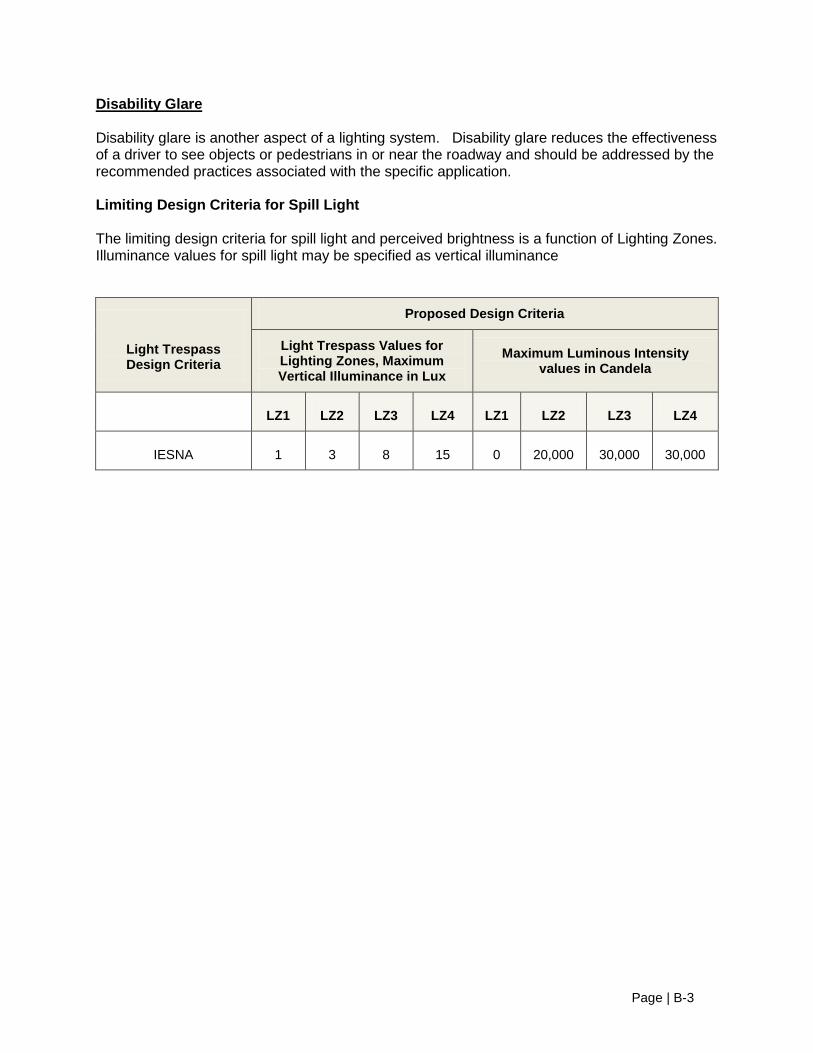
Disability Glare
Disability glare is another aspect of a lighting system. Disability glare reduces the effectiveness of a driver to see objects or pedestrians in or near the roadway and should be addressed by the recommended practices associated with the specific application. Limiting Design Criteria for Spill Light The limiting design criteria for spill light and perceived brightness is a function of Lighting Zones. Illuminance values for spill light may be specified as vertical illuminance
Light Trespass Design Criteria
Proposed Design Criteria
Light Trespass Values for Lighting Zones, Maximum Vertical Illuminance in Lux
Maximum Luminous Intensity values in Candela
LZ1 LZ2 LZ3 LZ4 LZ1 LZ2 LZ3 LZ4
IESNA 1 3 8 15 0 20,000 30,000 30,000

Page | B-1
APPENDIX B LED LUMINAIRE SPECIFICATIONS
Light Distribution – Photometric data per IESNA LM-79-08 and formatted per IESNA LM-63-02 as an .ies file.
Lumen Maintenance - Luminaire lumen depreciation data derived from Luminaire in-situ temperature measurement testing4 under UL1598 environments and directly correlated to LED package manufacturers IESNA LM-80-08 data.
Predicted Luminaire Lumen Depreciation Limits4 (% depreciation @50,000 hours of operation and 15°C1 operating ambient) as follows:
– < 15% @ 350mA Drive Current – < 20% @ 525mA Drive Current – ≤ 30% @ 700mA Drive Current
Lumen Depreciation (LD) Performance Data Sets – LED Luminaire Lumen Depreciation Data Sets to be created from correlated in-situ luminaire test methods4. The TS temperature is to be correlated directly to the LED chip package manufacturer’s LM-80-08 data to form data sets predicting luminaire lumen depreciation for the following luminaire average ambient operating conditions: 5°C, 10°C, 15°C, 20°C, 25°C and for the following operating durations: 25,000, 50,000 and 100,000 hours.
LED Life Rating (L70) – Defined as time of operation (in hours) to 30% lumen depreciation (i.e. 70% lumen maintenance), derived from Luminaire in-situ temperature measurement testing4 under UL1598 environments and directly correlated to LED package manufacturers IESNA LM-80-08 data.
Predicted L70 Limits (@ 25°C luminaire ambient operating environment) as follows: – > 100,000 hours @ 350mA Drive Current – > 65,000 hours @ 525mA Drive Current – > 45,000 hours @ 700mA Drive Current
Luminaire Operating Ambient Range – (-40°C – +40°C)2
Mechanical – Luminaire housing components to be low copper aluminum, with high performance heat sink(s) designed specifically for LED luminaires. No active cooling features (Fans, etc.). Luminaire configuration must allow for modular upgradability and/or field repair of all electrical components (i.e. LED modules, Driver(s), etc.).
A. Utilizes terminal block for power input suitable for #6 AWG wire B. Designed to mount on 1.25” IP and / or 2” IP horizontal tenon and is adjustable +/-
5 degrees to allow for fixture leveling
Lighting Controls Options – Provisions for compatibility with wireless (radio frequency, mesh network, etc.) and power line carrier lighting control protocols as follows:
– Tool-less access to LED Driver compartment – Tool-less removal of existing or standard LED driver and/or control gear – Tool-less installation of alternate LED driver and/or control gear

Page | B-2
Factory installed options – Ingress Protection (IP) Rating – IP66 – Internal Fusing – NEMA photo control receptacle – Backlight Cut-Off Shielding
Finish – Finish includes cleaning and preparing metal surface, electro-deposited epoxy primer and baked-on ultra-durable power coat. Salt fog test data to validate corrosion residence performance to be provided in accordance with the ASTM B 117 standard @ ≥ 5,000 hours.
Correlated Colour Temperature (CCT) and Colour Rendering Index (CRI) – CCT = 4000K ± 500K (other CCTs available upon request) – CRI ≥ 70
Warranty – 7 years on the LEDs, 7 years on the driver, 10 years on the paint finish
Electrical Safety – cUL and UL listed for Wet Location, ENEC, CE, ROHS and EMI. Class 1 rated. Internal surge protection – ≥9kV
Driver Specification 1. Electronic 2. Input Voltage range 120-277 ±10% (347-480V +/- 10% optional) 3. Output Current 0.35 A dc (+/- 5%), 0.53 A dc (+/- 5%), 0.70 A dc (+/- 5%) 4. Input Frequency 50/60 Hz 5. Power Factor >90% at full load 6. THD at full load is < 10% at 120V, <20% at 277V or 347V 7. Load regulation: +/- 1% from no load to full load 8. Output ripple <10% 9. Output should be isolated 10. Case temperature: rated for -40°C through +80°C 11. Overheat protection, self-limited short circuit protection and overload protected 12. Primary fused 13. Driver Life Rating: less than 0.5% failure rate at 150,000 operating hours (@ full
rated power and a minimum fixture operating ambient of 22°C)3
¹ A 15°C ambient condition conservatively represents the nighttime average ambient conditions for the mildest climate zones of Canada.
2 Active thermal monitoring and control circuitry will reduce drive current to protect the LED system components from exposure to elevated ambient conditions, above the rated luminaire ambient operating temperature limit.
3 Represented by accelerated life testing and electronic industry accepted component modelin
4 LED chip package temperature (TS) measurement obtained with the LED chip package operating in given luminaire and in a given stabilized ambient environment.
Page | B-3
APPENDIX C US DOE LED SPECIFICATIONS
PART 1 – GENERAL
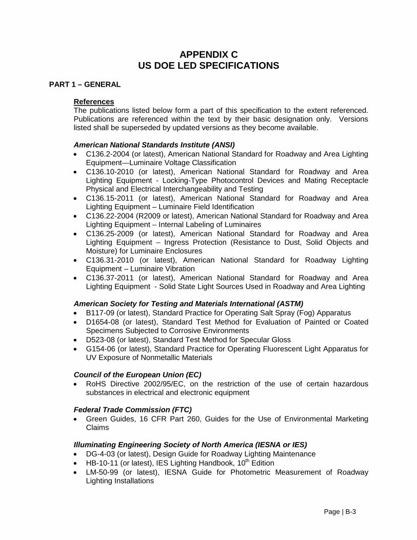
The publications listed below form a part of this specification to the extent referenced. Publications are referenced within the text by their basic designation only. Versions listed shall be superseded by updated versions as they become available.
References
American National Standards Institute (ANSI) • C136.2-2004 (or latest), American National Standard for Roadway and Area Lighting
Equipment—Luminaire Voltage Classification • C136.10-2010 (or latest), American National Standard for Roadway and Area
Lighting Equipment - Locking-Type Photocontrol Devices and Mating Receptacle Physical and Electrical Interchangeability and Testing
• C136.15-2011 (or latest), American National Standard for Roadway and Area Lighting Equipment – Luminaire Field Identification
• C136.22-2004 (R2009 or latest), American National Standard for Roadway and Area Lighting Equipment – Internal Labeling of Luminaires
• C136.25-2009 (or latest), American National Standard for Roadway and Area Lighting Equipment – Ingress Protection (Resistance to Dust, Solid Objects and Moisture) for Luminaire Enclosures
• C136.31-2010 (or latest), American National Standard for Roadway Lighting Equipment – Luminaire Vibration
• C136.37-2011 (or latest), American National Standard for Roadway and Area Lighting Equipment - Solid State Light Sources Used in Roadway and Area Lighting
American Society for Testing and Materials International (ASTM) • B117-09 (or latest), Standard Practice for Operating Salt Spray (Fog) Apparatus • D1654-08 (or latest), Standard Test Method for Evaluation of Painted or Coated
Specimens Subjected to Corrosive Environments • D523-08 (or latest), Standard Test Method for Specular Gloss • G154-06 (or latest), Standard Practice for Operating Fluorescent Light Apparatus for
UV Exposure of Nonmetallic Materials
Council of the European Union (EC) • RoHS Directive 2002/95/EC, on the restriction of the use of certain hazardous
substances in electrical and electronic equipment
Federal Trade Commission (FTC) • Green Guides, 16 CFR Part 260, Guides for the Use of Environmental Marketing
Claims
Illuminating Engineering Society of North America (IESNA or IES) • DG-4-03 (or latest), Design Guide for Roadway Lighting Maintenance • HB-10-11 (or latest), IES Lighting Handbook, 10th Edition • LM-50-99 (or latest), IESNA Guide for Photometric Measurement of Roadway
Lighting Installations

Page | B-4
• LM-61-06 (or latest), IESNA Approved Guide for Identifying Operating Factors Influencing Measured Vs. Predicted Performance for Installed Outdoor High Intensity Discharge (HID) Luminaires
• LM-79-08 (or latest), IESNA Approved Method for the Electrical and Photometric Measurements of Solid-Sate Lighting Products
• LM-80-08 (or latest), IESNA Approved Method for Measuring Lumen Maintenance of LED Light Sources
• RP-8-00 (or latest), ANSI / IESNA American National Standard Practice for Roadway Lighting
• RP-16-10 (or latest), ANSI/IES Nomenclature and Definitions for Illuminating Engineering
• TM-3-95 (or latest), A Discussion of Appendix E - "Classification of Luminaire Lighting Distribution," from ANSI/IESNA RP-8-83
• TM-15-11 (or latest), Luminaire Classification System for Outdoor Luminaires • TM-21-11 (or latest), Projecting Long Term Lumen Maintenance of LED Light
Sources
Institute of Electrical and Electronics Engineers (IEEE) • IEEE C62.41.2-2002 (or latest), IEEE Recommended Practice on Characterization of
Surges in Low-Voltage (1000 V and less) AC Power Circuits • ANSI/IEEE C62.45-2002 (or latest), IEEE Recommended Practice on Surge Testing
for Equipment Connected to Low-Voltage (1000 V and Less) AC Power Circuits
National Electrical Manufacturers Association (NEMA) • ANSI/NEMA/ANSLG C78.377-2008 (or latest), American National Standard for the
Chromaticity of Solid State Lighting Products
National Fire Protection Association (NFPA) • 70 – National Electrical Code (NEC)
Underwriters Laboratories (UL) • 1449, Surge Protective Devices • 1598, Luminaires • 8750, Light Emitting Diode (LED) Equipment for Use in Lighting Products
1.1.
Related Documents
Contract Drawings and conditions of Contract (including General Conditions, Addendum to the General Conditions, Special Conditions, Division 01 Specifications Sections and all other Contract Documents) apply to the work of this section. See the separate Specification for Adaptive Control and Remote Monitoring of LED Roadway Luminaires for additional driver performance and interface requirements.
1.2.
Definitions
Lighting terminology used herein is defined in IES RP-16. See referenced documents for additional definitions. 1. Exception: The term “driver” is used herein to broadly cover both drivers and power
supplies, where applicable.

Page | B-5
2. Clarification: The term “LED light source(s)” is used herein per IES LM-80 to broadly
cover LED package(s), module(s), and array(s).
1.3.
Quality Assurance
Before approval and purchase, Owner may request luminaire sample(s) identical to product configuration(s) submitted for inspection. Owner may request IES LM-79 testing of luminaire sample(s) to verify performance is within manufacturer-reported tolerances. After installation, Owner may perform IES LM-50 field measurements to verify performance requirements outlined in Appendix A, giving consideration to measurement uncertainties outlined in IES LM-61.
1.4.
Lighting System Performance
Energy Conservation
Connected Load • Luminaires shall have maximum nominal luminaire input wattage as specified for
each luminaire type in Appendix A. Lighting Controls • See separate controls specification identified in section 1.2 above, if applicable. • See section 2.1-B below for driver control interface and performance requirements. • See section 2.1-K below for photocontrol receptacle requirements.
Photometric Requirements
Luminaires shall meet the general criteria provided in the body of this specification and the particular criteria for each luminaire type defined in Appendix A.
1.5.
Required Submittals for Each Luminaire Type Defined in Appendix A
General submittal content shall include 1. Completed Appendix E submittal form 2. Luminaire cutsheets 3. Cutsheets for LED light sources 4. Cutsheets for LED driver(s) - If dimmable LED driver is specified, provide
diagrams illustrating light output and input power as a function of control signal. 5. Cutsheets for surge protection device, if applicable 6. Instructions for installation and maintenance 7. Summary of luminaire recycled content and recyclability per the FTC Green Guides,
expressed by percentage of luminaire weight
LM-79 luminaire photometric report(s) shall be produced by the test laboratory and include 1. Name of test laboratory (The test laboratory must hold National Voluntary Laboratory
Accreditation Program (NVLAP) accreditation for the IES LM-79 test procedure or must be qualified, verified, and recognized through the U.S. Department of Energy’s CALiPER program. For more information, see
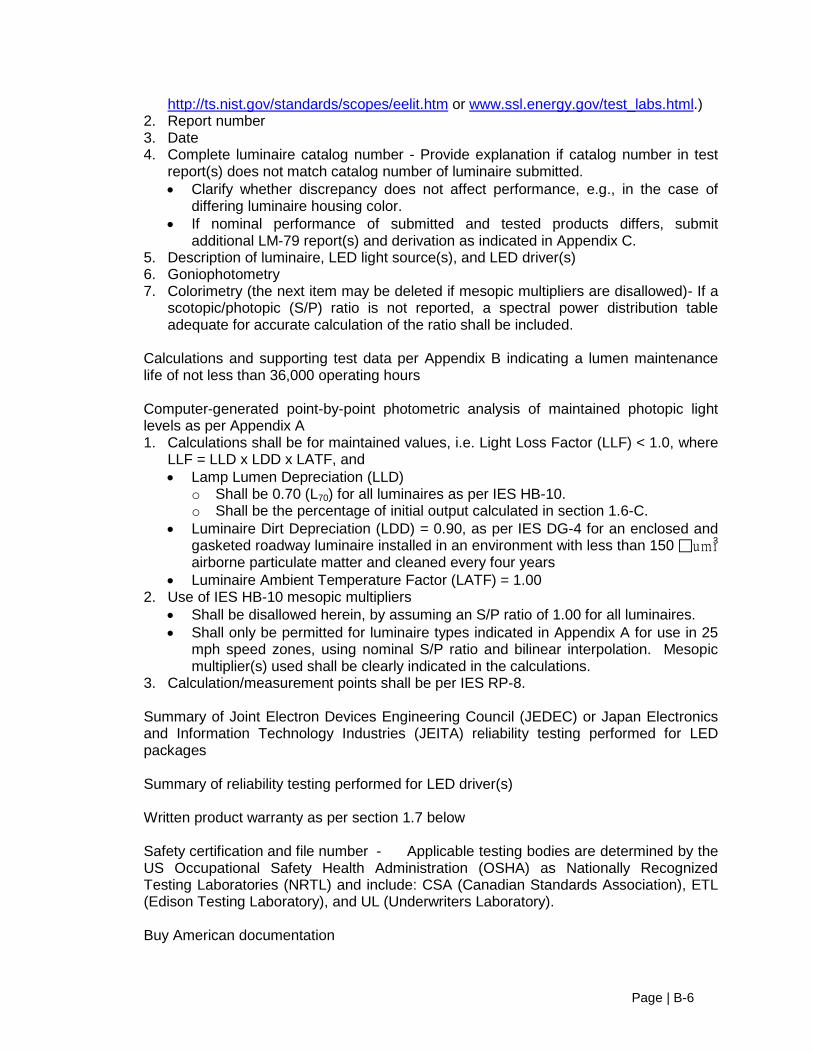
Page | B-6
http://ts.nist.gov/standards/scopes/eelit.htm or www.ssl.energy.gov/test_labs.html.) 2. Report number 3. Date 4. Complete luminaire catalog number - Provide explanation if catalog number in test
report(s) does not match catalog number of luminaire submitted. • Clarify whether discrepancy does not affect performance, e.g., in the case of
differing luminaire housing color. • If nominal performance of submitted and tested products differs, submit
additional LM-79 report(s) and derivation as indicated in Appendix C. 5. Description of luminaire, LED light source(s), and LED driver(s) 6. Goniophotometry 7. Colorimetry (the next item may be deleted if mesopic multipliers are disallowed)- If a
scotopic/photopic (S/P) ratio is not reported, a spectral power distribution table adequate for accurate calculation of the ratio shall be included.
Calculations and supporting test data per Appendix B indicating a lumen maintenance life of not less than 36,000 operating hours
Computer-generated point-by-point photometric analysis of maintained photopic light levels as per Appendix A 1. Calculations shall be for maintained values, i.e. Light Loss Factor (LLF) < 1.0, where
LLF = LLD x LDD x LATF, and • Lamp Lumen Depreciation (LLD)
o Shall be 0.70 (L70) for all luminaires as per IES HB-10. o Shall be the percentage of initial output calculated in section 1.6-C.
• Luminaire Dirt Depreciation (LDD) = 0.90, as per IES DG-4 for an enclosed and gasketed roadway luminaire installed in an environment with less than 150 umi3 airborne particulate matter and cleaned every four years
• Luminaire Ambient Temperature Factor (LATF) = 1.00 2. Use of IES HB-10 mesopic multipliers
• Shall be disallowed herein, by assuming an S/P ratio of 1.00 for all luminaires. • Shall only be permitted for luminaire types indicated in Appendix A for use in 25
mph speed zones, using nominal S/P ratio and bilinear interpolation. Mesopic multiplier(s) used shall be clearly indicated in the calculations.
3. Calculation/measurement points shall be per IES RP-8.
Summary of Joint Electron Devices Engineering Council (JEDEC) or Japan Electronics and Information Technology Industries (JEITA) reliability testing performed for LED packages Summary of reliability testing performed for LED driver(s) Written product warranty as per section 1.7 below
Safety certification and file number - Applicable testing bodies are determined by the US Occupational Safety Health Administration (OSHA) as Nationally Recognized Testing Laboratories (NRTL) and include: CSA (Canadian Standards Association), ETL (Edison Testing Laboratory), and UL (Underwriters Laboratory).
Buy American documentation

Page | B-7
1. Manufacturers listed on the current NEMA Listing of Companies Offering Outdoor Luminaires Manufactured in U.S.A. for Recovery Act Projects need only provide a copy of the document (http://www.nema.org/gov/economic-stimulus).
2. Other manufacturers shall submit documentation as per the DOE Guidance on Documenting Compliance with the Recovery Act Buy American Provisions (http://www1.eere.energy.gov/recovery/buy_american_provision.html).
1.6.
Warranty
Provide a minimum five-year warranty covering maintained integrity and functionality of
Luminaire housing, wiring, and connections • LED light source(s) - Negligible light output from more than 10 percent of the LED
packages constitutes luminaire failure. LED driver(s)
Warranty period shall begin 90 days after date of invoice, or as negotiated by owner such as in the case of an auditable asset management system.
PART 2 – PRODUCTS 2.1.
Luminaire Requirements
General Requirements 1. Luminaires shall be as specified for each type in Appendix A. 2. Luminaire shall have an external label per ANSI C136.15 3. Luminaire shall have an internal label per ANSI C136.22. 4. Nominal luminaire input wattage shall account for nominal applied voltage and any
reduction in driver efficiency due to sub-optimal driver loading. 5. Luminaires shall start and operate in -20°C to +40°C ambient. 6. Electrically test fully assembled luminaires before shipment from factory. 7. Effective Projected Area (EPA) and weight of the luminaire shall not exceed the
values indicated in Appendix A. 8. Luminaires shall be designed for ease of component replacement and end-of-life
disassembly. 9. Luminaires shall be rated for the ANSI C136.31 Vibration Level indicated in Appendix
A. 10. LED light source(s) and driver(s) shall be RoHS compliant. 11. Transmissive optical components shall be applied in accordance with OEM design
guidelines to ensure suitability for the thermal/mechanical/chemical environment.
Driver 1. Rated case temperature shall be suitable for operation in the luminaire operating in
the ambient temperatures indicated in section 2.1-A above. 2. Shall accept the voltage or voltage range indicated in Appendix A at 50/60 Hz, and
shall operate normally for input voltage fluctuations of plus or minus 10 percent. 3. Shall have a minimum Power Factor (PF) of 0.90 at full input power and across
specified voltage range. 4. Control signal interface
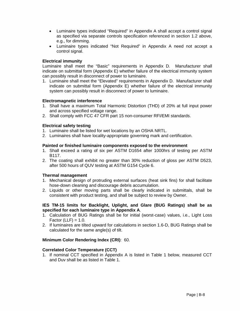
Page | B-8
• Luminaire types indicated “Required” in Appendix A shall accept a control signal as specified via separate controls specification referenced in section 1.2 above, e.g., for dimming.
• Luminaire types indicated “Not Required” in Appendix A need not accept a control signal.
Electrical immunity Luminaire shall meet the “Basic” requirements in Appendix D. Manufacturer shall indicate on submittal form (Appendix E) whether failure of the electrical immunity system can possibly result in disconnect of power to luminaire. 1. Luminaire shall meet the “Elevated” requirements in Appendix D. Manufacturer shall
indicate on submittal form (Appendix E) whether failure of the electrical immunity system can possibly result in disconnect of power to luminaire.
Electromagnetic interference 1. Shall have a maximum Total Harmonic Distortion (THD) of 20% at full input power
and across specified voltage range. 2. Shall comply with FCC 47 CFR part 15 non-consumer RFI/EMI standards.
Electrical safety testing 1. Luminaire shall be listed for wet locations by an OSHA NRTL. 2. Luminaires shall have locality-appropriate governing mark and certification.
Painted or finished luminaire components exposed to the environment 1. Shall exceed a rating of six per ASTM D1654 after 1000hrs of testing per ASTM
B117. 2. The coating shall exhibit no greater than 30% reduction of gloss per ASTM D523,
after 500 hours of QUV testing at ASTM G154 Cycle 6.
Thermal management 1. Mechanical design of protruding external surfaces (heat sink fins) for shall facilitate
hose-down cleaning and discourage debris accumulation. 2. Liquids or other moving parts shall be clearly indicated in submittals, shall be
consistent with product testing, and shall be subject to review by Owner.
IES TM-15 limits for Backlight, Uplight, and Glare (BUG Ratings) shall be as specified for each luminaire type in Appendix A. 1. Calculation of BUG Ratings shall be for initial (worst-case) values, i.e., Light Loss
Factor (LLF) = 1.0. 2. If luminaires are tilted upward for calculations in section 1.6-D, BUG Ratings shall be
calculated for the same angle(s) of tilt.
Minimum Color Rendering Index (CRI): 60.
Correlated Color Temperature (CCT) 1. If nominal CCT specified in Appendix A is listed in Table 1 below, measured CCT
and Duv shall be as listed in Table 1.

Page | B-9
Table 1. Allowable CCT and Duv (adapted from NEMA C78.377)
Manufacturer-Rated
Nominal CCT (K) Allowable LM-79 Chromaticity Values
Measured CCT (K) Measured Duv 2700 2580 to 2870 -0.006 to 0.006 3000 2870 to 3220 -0.006 to 0.006 3500 3220 to 3710 -0.006 to 0.006 4000 3710 to 4260 -0.005 to 0.007 4500 4260 to 4746 -0.005 to 0.007 5000 4745 to 5311 -0.004 to 0.008 5700 5310 to 6020 -0.004 to 0.008 6500 6020 to 7040 -0.003 to 0.009
2. If nominal CCT specified in Appendix A is not listed in Table 1, measured CCT and
Duv shall be as per the criteria for Flexible CCT defined in NEMA C78.377.
The following shall be in accordance with corresponding sections of ANSI C136.37 1. Wiring and grounding - All internal components shall be assembled and pre-wired
using modular electrical connections. 2. Mounting provisions - Specific configurations are indicated in Appendix A 3. Terminal blocks for incoming AC lines 4. Photocontrol receptacle 5. Latching and hinging 6. Ingress protection
2.2.
Product Manufacturers
Any manufacturer offering products that comply with the required product performance and operation criteria may be considered.
2.3.
Manufacturer Services
Manufacturer or local sales representative shall provide installation and troubleshooting support via telephone and/or email.

Page | B-11
Estimating LED Lumen Maintenance IES TM-21 allows for extrapolation of expected lumen maintenance from available test data. The extent of such extrapolation is limited by the duration of testing completed and the number of samples used in the testing. The TM-21 methodology shall be used by the manufacturer to determine lamp lumen depreciation (LLD) at end of lumen maintenance life per section 1.6-C. The applicant may estimate lumen maintenance in one of two ways:
Option 1: Component Performance
Under this compliance path, the applicant must submit calculations per TM-21 predicting lumen maintenance at the luminaire level using In Situ Temperature Measurement Testing (ISTMT) and LM-80 data. To be eligible for the Component Performance option, ALL of the conditions below must be met. If ANY of the conditions is not met, the component performance option may not be used and the applicant must use Option 2 for compliance. 1. The LED light source(s) have been tested according to LM-80.
2. The LED drive current specified by the luminaire manufacturer is less than or equal to the drive current specified in the LM-80 test report.
3. The LED light source(s) manufacturer prescribes/indicates a temperature measurement point (TS) on the light source(s).
4. The TS is accessible to allow temporary attachment of a thermocouple for measurement of in situ temperature. Access via a temporary hole in the housing, tightly resealed during testing with putty or other flexible sealant is allowable.
5. For the hottest LED light source in the luminaire, the temperature measured at the TS during ISTMT is less than or equal to the temperature specified in the LM-80 test report for the corresponding drive current or higher, within the manufacturer’s specified operating current range.
• The ISTMT laboratory must be approved by OSHA as a Nationally Recognized Testing Lab (NRTL), must be qualified, verified, and recognized through DOE’s CALiPER program, or must be recognized through UL’s Data Acceptance Program.
• The ISTMT must be conducted with the luminaire installed in the appropriate application as defined by ANSI/UL 1598 (hardwired luminaires), with bird-fouling appropriately simulated (and documented by photograph) as determined by the manufacturer.
Option 2: Luminaire Performance
Under this compliance path, the applicant must submit TM-21 calculations based on LM-79 photometric test data for no less than three samples of the entire luminaire. Duration of operation and interval between photometric tests shall conform to the TM-21 criteria for LED light sources. For example, testing solely at 0 and 6000 hours of operation would not be adequate for the purposes of extrapolation.
Between LM-79 tests, the luminaire test samples must be operated long-term in the appropriate application as defined by ANSI/UL 1598 (hardwired luminaires). The test laboratory must hold NVLAP accreditation for the LM-79 test procedure or must be qualified, verified, and recognized
Page | B-12
through the U.S. Department of Energy (DOE)’s CALiPER program. The extent of allowable extrapolation (either 5.5 or 6 times the test duration) depends on the total number of LED light sources (no less than 10 and preferably more than 19) installed in the luminaire samples, as per TM-21.
This compliance path poses a greater testing burden to luminaire manufacturers but incorporates long-term testing of other components in the system, such as drivers. Under either compliance path, values used for extrapolation shall be summarized per TM-21 Tables 1 and 2. Submitted values for lumen maintenance lifetime and the associated percentage lumen maintenance shall be “reported” rather than “projected” as defined by TM-21. Supporting diagrams are requested to facilitate interpretation by Owner.

P a g e | C-1
PRODUCT FAMILY TESTING LM-79 AND ISTMT
It is recognized that due to the time and cost required for product testing, it would not be realistic to expect manufacturers offering a multitude of unique luminaire configurations to test every possible configuration. Therefore, the “product families” method may be utilized for LM-79 and ISTMT, whereby manufacturers identify a set of representative products for which test data can be used to demonstrate the accuracy of interpolated or extrapolated performance of product configurations lacking test data. Precedent for this approach can be found in LM-80. If the particular luminaire configuration submitted has not been tested, the performance may be conservatively represented by test data for another luminaire configuration having: • The same intensity distribution (typically only applies to LM-79) • The same or lower nominal CCT • The same or higher nominal drive current • The same or greater number of LED light source(s) • The same or lower percentage driver loading and efficiency • The same or smaller size luminaire housing. A more accurate estimate of performance can be obtained by linear interpolation between two or more tests differing in terms of the six parameters listed above. For example, consider a hypothetical luminaire offered in a single size housing, and having the following parameters: • Three intensity distributions: IES Type II, III, or IV • Three CCTs: 4000, 5000, and 6000K • Three drive currents: 350, 525, and 700 mA • Four LED quantities: 20, 40, 60, or 80 LEDs. Table C.1 illustrates a set of tests which could allow for accurate interpolation between tested configurations, given a single luminaire housing size and essentially constant driver efficiency; these 10 tests may provide representative data for the 108 possible product configurations. Note that normalized intensity distribution must not be affected by the other three parameters.
Table C.1. Representative testing of a single luminaire housing size
Tests Intensity distribution (IES Type)
CCT (K)
Drive current (mA)
# of LEDs
1, 2, 3 II, III, IV 4000 700 80
4, 5 IV 5000, 6000 700 80
6, 7 IV 4000 325, 525 80 8, 9, 10 IV 4000 700 20, 40, 60
For example, the manufacturer could detail interpolation as shown in Table C.2, applying the following multipliers to the base test #2 to model a configuration with Type III intensity distribution, 5000K CCT, 525 mA drive current, and 40 LEDs: • Ratio of test #4 lumens to test #3 lumens

P a g e | C-2
• Ratio of test #7 lumens to test #3 lumens • Ratio of test #9 lumens to test #3 lumens.
Table C.2. Multipliers for Test #2 to yield: Type III , 5000K, 525mA, 40 LEDs
Test # Intensity distribution
(IES Type) CCT (K)
Drive current
(mA) # of LEDs
Multiplier (lumens ratio)
2 III 4000 700 80 n/a 3 IV 4000 700 80 n/a 4 IV 5000 700 80 #4 / #3 7 IV 4000 525 80 #7 / #3 9 IV 4000 700 40 #9 / #3
Interpolation between minimal LM-79 and ISTMT data is more difficult if housing size increases with increasing wattage; it may not be clear whether the lowest-wattage configuration would be expected to “run cooler” than the highest-wattage configuration. In these circumstances, the adequacy of submitted data is subject to Owner approval. At this time, the “successor” method cannot be used; luminaires tested must utilize the LED light source(s) characterized by the submitted LM-80 report.
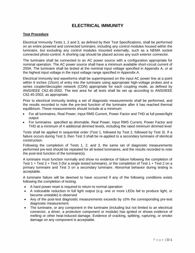
P a g e | D-1
ELECTRICAL IMMUNITY
Test Procedure
Electrical Immunity Tests 1, 2 and 3, as defined by their Test Specifications, shall be performed on an entire powered and connected luminaire, including any control modules housed within the luminaire, but excluding any control modules mounted externally, such as a NEMA socket connected photo-control. A shorting cap should be placed across any such exterior connector.
The luminaire shall be connected to an AC power source with a configuration appropriate for nominal operation. The AC power source shall have a minimum available short-circuit current of 200A. The luminaire shall be tested at the nominal input voltage specified in Appendix A, or at the highest input voltage in the input voltage range specified in Appendix A.
Electrical Immunity test waveforms shall be superimposed on the input AC power line at a point within 6 inches (15cm) of entry into the luminaire using appropriate high-voltage probes and a series coupler/decoupler network (CDN) appropriate for each coupling mode, as defined by ANSI/IEEE C62.45-2002. The test area for all tests shall be set up according to ANSI/IEEE C62.45-2002, as appropriate.
Prior to electrical immunity testing a set of diagnostic measurements shall be performed, and the results recorded to note the pre-test function of the luminaire after it has reached thermal equilibrium. These measurements should include at a minimum: • For all luminaires, Real Power, Input RMS Current, Power Factor and THD at full power/light
output • For luminaires specified as dimmable, Real Power, Input RMS Current, Power Factor and
THD at a minimum of 4 additional dimmed levels, including the rated minimum dimmed level
Tests shall be applied in sequential order (Test 1, followed by Test 2, followed by Test 3). If a failure occurs during Test 3, then Test 3 shall be re-applied to a secondary luminaire of identical construction. Following the completion of Tests 1, 2, and 3, the same set of diagnostic measurements performed pre-test should be repeated for all tested luminaires, and the results recorded to note the post-test function of the luminaire(s).
A luminaire must function normally and show no evidence of failure following the completion of Test 1 + Test 2 + Test 3 (for a single tested luminaire), or the completion of Test 1 + Test 2 on a primary luminaire and Test 3 on a secondary luminaire. Abnormal behavior during testing is acceptable.
A luminaire failure will be deemed to have occurred if any of the following conditions exists following the completion of testing: • A hard power reset is required to return to normal operation • A noticeable reduction in full light output (e.g. one or more LEDs fail to produce light, or
become unstable) is observed • Any of the post-test diagnostic measurements exceeds by ±5% the corresponding pre-test
diagnostic measurement. • The luminaire, or any component in the luminaire (including but not limited to an electrical
connector, a driver, a protection component or module) has ignited or shows evidence of melting or other heat-induced damage. Evidence of cracking, splitting, rupturing, or smoke damage on any component is acceptable.

P a g e | D-2
NOTE: L1 is typically “HOT”, L2 is typically “NEUTRAL” and PE = Protective Earth.
Test Specifications
Test 1: Ring Wave:
The luminaire shall be subjected to repetitive strikes of a “C Low Ring Wave” as defined in IEEE C62.41.2-2002, Scenario 1, Location Category C. The test strikes shall be applied as specified by Table D.1. Prior to testing, the ring wave generator shall be calibrated to simultaneously meet BOTH the specified short circuit current peak and open circuit voltage peak MINIMUM requirements. Note that this may require that the generator charging voltage be raised above the specified level to obtain the specified current peak. Calibrated current probes/transformers designed for measuring high-frequency currents shall be used to measure test waveform currents.
Test waveform current shapes and peaks for all strikes shall be compared to ensure uniformity throughout each set (coupling mode + polarity/phase angle) of test strikes, and the average peak current shall be calculated and recorded. If any individual peak current in a set exceeds by ±10% the average, the test setup shall be checked, and the test strikes repeated.
Table D.1: 0.5 µS – 100Hz Ring Wave Specification
Parameter Test Level/Configuration Short Circuit Current Peak 0.5 kA Open Circuit Voltage Peak 6 kV Source Impedance 12 Ω Coupling Modes L1 to PE, L2 to PE, L1 to L2 Polarity and Phase Angle Positive at 90° and Negative at 270° Test Strikes 5 for each Coupling Mode and Polarity/Phase Angle
combination Time between Strikes 1 minute Total Number of Strikes = 5 strikes x 4 coupling modes x 2 polarity/phase angles
= 40 total strikes Test 2: Combination Wave: The luminaire shall be subjected to repetitive strikes of a “C High Combination Wave” or “C Low Combination Wave”, as defined in IEEE C62.41.2-2002, Scenario 1, Location Category C. The test strikes shall be applied as specified by Table D.2. The “Low” test level shall be used for luminaires with Basic Electrical Immunity requirements, while the “High” test level shall be used for luminaires with Elevated Electrical Immunity requirements. Prior to testing, the combination wave generator shall be calibrated to simultaneously meet BOTH the specified short circuit current peak and open circuit voltage peak MINIMUM requirements. Note that this may require that the generator charging voltage be raised above the specified level to obtain the specified current peak. Calibrated current probes/transformers designed for measuring high-frequency currents shall be used to measure test waveform currents.
Test waveform current shapes and peaks for all strikes shall be compared to ensure uniformity throughout each set (coupling mode + polarity/phase angle) of test strikes, and the average peak current shall be calculated and recorded. If any individual peak current in a set exceeds by ±10% the average, the test setup shall be checked, and the test strikes repeated.
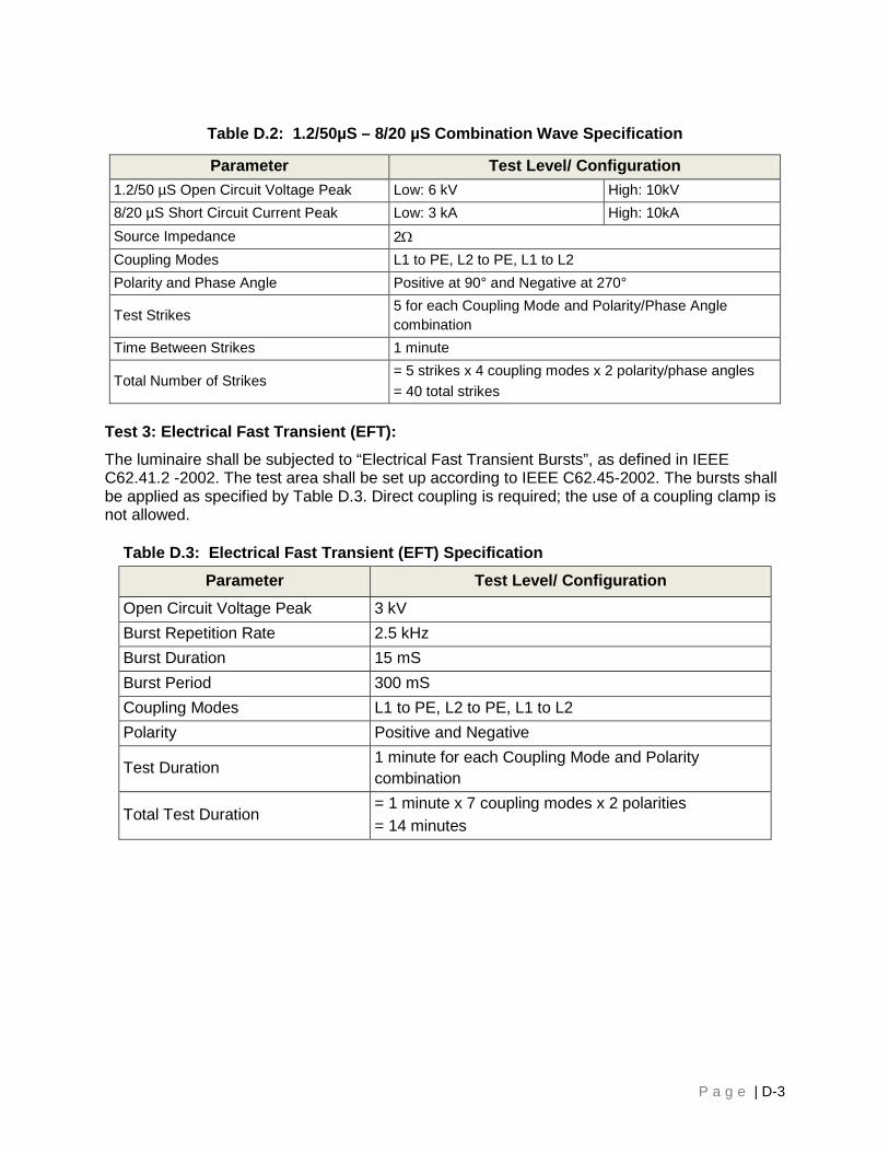
P a g e | D-3
Table D.2: 1.2/50µS – 8/20 µS Combination Wave Specification
Parameter Test Level/ Configuration 1.2/50 µS Open Circuit Voltage Peak Low: 6 kV High: 10kV 8/20 µS Short Circuit Current Peak Low: 3 kA High: 10kA Source Impedance 2Ω Coupling Modes L1 to PE, L2 to PE, L1 to L2 Polarity and Phase Angle Positive at 90° and Negative at 270°
Test Strikes 5 for each Coupling Mode and Polarity/Phase Angle combination
Time Between Strikes 1 minute
Total Number of Strikes = 5 strikes x 4 coupling modes x 2 polarity/phase angles = 40 total strikes
Test 3: Electrical Fast Transient (EFT): The luminaire shall be subjected to “Electrical Fast Transient Bursts”, as defined in IEEE C62.41.2 -2002. The test area shall be set up according to IEEE C62.45-2002. The bursts shall be applied as specified by Table D.3. Direct coupling is required; the use of a coupling clamp is not allowed.
Table D.3: Electrical Fast Transient (EFT) Specification Parameter Test Level/ Configuration
Open Circuit Voltage Peak 3 kV Burst Repetition Rate 2.5 kHz Burst Duration 15 mS Burst Period 300 mS Coupling Modes L1 to PE, L2 to PE, L1 to L2 Polarity Positive and Negative
Test Duration 1 minute for each Coupling Mode and Polarity combination
Total Test Duration = 1 minute x 7 coupling modes x 2 polarities = 14 minutes
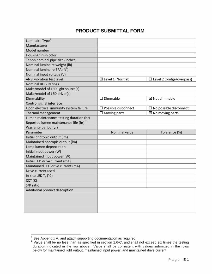
P a g e | E-1
PRODUCT SUBMITTAL FORM
Luminaire Type1 Manufacturer Model number Housing finish color Tenon nominal pipe size (inches) Nominal luminaire weight (lb) Nominal luminaire EPA (ft2) Nominal input voltage (V) ANSI vibration test level Level 1 (Normal) Level 2 (bridge/overpass) Nominal BUG Ratings Make/model of LED light source(s) Make/model of LED driver(s) Dimmability Dimmable Not dimmable Control signal interface Upon electrical immunity system failure Possible disconnect No possible disconnect Thermal management Moving parts No moving parts Lumen maintenance testing duration (hr) Reported lumen maintenance life (hr) 2 Warranty period (yr) Parameter Nominal value Tolerance (%) Initial photopic output (lm) Maintained photopic output (lm) Lamp lumen depreciation Initial input power (W) Maintained input power (W) Initial LED drive current (mA) Maintained LED drive current (mA) Drive current used In‐situ LED Tc (°C) CCT (K) S/P ratio Additional product description
1 See Appendix A, and attach supporting documentation as required. 2 Value shall be no less than as specified in section 1.6-C, and shall not exceed six times the testing duration indicated in the row above. Value shall be consistent with values submitted in the rows below for maintained light output, maintained input power, and maintained drive current.