stratix 2500 lightly managed switches user manual, 1783 ... · monitor stratix® 2500 lightly...
TRANSCRIPT

Stratix 2500 Lightly Managed SwitchesCatalog Numbers 1783-LMS5, 1783-LMS8
User ManualOriginal Instructions

Important User Information
Read this document and the documents listed in the additional resources section about installation, configuration, and operation of this equipment before you install, configure, operate, or maintain this product. Users are required to familiarize themselves with installation and wiring instructions in addition to requirements of all applicable codes, laws, and standards.
Activities including installation, adjustments, putting into service, use, assembly, disassembly, and maintenance are required to be carried out by suitably trained personnel in accordance with applicable code of practice.
If this equipment is used in a manner not specified by the manufacturer, the protection provided by the equipment may be impaired.
In no event will Rockwell Automation, Inc. be responsible or liable for indirect or consequential damages resulting from the use or application of this equipment.
The examples and diagrams in this manual are included solely for illustrative purposes. Because of the many variables and requirements associated with any particular installation, Rockwell Automation, Inc. cannot assume responsibility or liability for actual use based on the examples and diagrams.
No patent liability is assumed by Rockwell Automation, Inc. with respect to use of information, circuits, equipment, or software described in this manual.
Reproduction of the contents of this manual, in whole or in part, without written permission of Rockwell Automation, Inc., is prohibited
Throughout this manual, when necessary, we use notes to make you aware of safety considerations.
Labels may also be on or inside the equipment to provide specific precautions.
WARNING: Identifies information about practices or circumstances that can cause an explosion in a hazardous environment, which may lead to personal injury or death, property damage, or economic loss.
ATTENTION: Identifies information about practices or circumstances that can lead to personal injury or death, property damage, or economic loss. Attentions help you identify a hazard, avoid a hazard, and recognize the consequence.
IMPORTANT Identifies information that is critical for successful application and understanding of the product.
SHOCK HAZARD: Labels may be on or inside the equipment, for example, a drive or motor, to alert people that dangerous voltage may be present.
BURN HAZARD: Labels may be on or inside the equipment, for example, a drive or motor, to alert people that surfaces may reach dangerous temperatures.
ARC FLASH HAZARD: Labels may be on or inside the equipment, for example, a motor control center, to alert people to potential Arc Flash. Arc Flash will cause severe injury or death. Wear proper Personal Protective Equipment (PPE). Follow ALL Regulatory requirements for safe work practices and for Personal Protective Equipment (PPE).

Table of Contents
Preface . . . . . . . . . . . . . . . . . . . . . . . . . . . . . . . . . . . . . . . . . . . . . . . . . . . . . . . . .7Summary of Changes . . . . . . . . . . . . . . . . . . . . . . . . . . . . . . . . . . . . . . . . . . . 7Access Product Release Notes . . . . . . . . . . . . . . . . . . . . . . . . . . . . . . . . . . . 7Additional Resources . . . . . . . . . . . . . . . . . . . . . . . . . . . . . . . . . . . . . . . . . . . 8
Chapter 1About the Switches EtherNet/IP CIP Interface. . . . . . . . . . . . . . . . . . . . . . . . . . . . . . . . . . . . . 10
CIP Network Connections. . . . . . . . . . . . . . . . . . . . . . . . . . . . . . . . . 10RSLinx Software and Network Who Support . . . . . . . . . . . . . . . . 11Electronic Data Sheet (EDS) Files . . . . . . . . . . . . . . . . . . . . . . . . . . 11Data Accessible with CIP . . . . . . . . . . . . . . . . . . . . . . . . . . . . . . . . . . 12
Software Features . . . . . . . . . . . . . . . . . . . . . . . . . . . . . . . . . . . . . . . . . . . . . 13Hardware Features . . . . . . . . . . . . . . . . . . . . . . . . . . . . . . . . . . . . . . . . . . . . 13
Chapter 2Get Started Out-of-the-box Configuration . . . . . . . . . . . . . . . . . . . . . . . . . . . . . . . . . 16
Express Setup Configuration . . . . . . . . . . . . . . . . . . . . . . . . . . . . . . . . . . . . . . . . . . . . . . . . 16
Express Setup Button . . . . . . . . . . . . . . . . . . . . . . . . . . . . . . . . . . . . . . 17Express Setup Modes . . . . . . . . . . . . . . . . . . . . . . . . . . . . . . . . . . . . . . 17Express Setup Requirements . . . . . . . . . . . . . . . . . . . . . . . . . . . . . . . . 18Run Express Setup in Short Press Mode . . . . . . . . . . . . . . . . . . . . . 19Run Express Setup in Medium Press Mode . . . . . . . . . . . . . . . . . . 21Run Express Setup in Long Press Mode. . . . . . . . . . . . . . . . . . . . . . 22
Network Settings in Device Manager . . . . . . . . . . . . . . . . . . . . . . . . . . . 22Plug and Play Mode. . . . . . . . . . . . . . . . . . . . . . . . . . . . . . . . . . . . . . . . 22Express Setup Mode . . . . . . . . . . . . . . . . . . . . . . . . . . . . . . . . . . . . . . . 23
Configure Network Settings in the Logix Designer Application . . . 26Configuration in Device Manager . . . . . . . . . . . . . . . . . . . . . . . . . . . . . . 29
Access Device Manager . . . . . . . . . . . . . . . . . . . . . . . . . . . . . . . . . . . . 30Configure Port Settings . . . . . . . . . . . . . . . . . . . . . . . . . . . . . . . . . . . . 32
Configuration in the Studio 5000 Environment . . . . . . . . . . . . . . . . . 35General Properties . . . . . . . . . . . . . . . . . . . . . . . . . . . . . . . . . . . . . . . . . 36Connection Properties . . . . . . . . . . . . . . . . . . . . . . . . . . . . . . . . . . . . . 38Switch Configuration . . . . . . . . . . . . . . . . . . . . . . . . . . . . . . . . . . . . . . 39Port Configuration . . . . . . . . . . . . . . . . . . . . . . . . . . . . . . . . . . . . . . . . 41
User Administration in Device Manager . . . . . . . . . . . . . . . . . . . . . . . . 42Configuration Files. . . . . . . . . . . . . . . . . . . . . . . . . . . . . . . . . . . . . . . . . . . . 44
Manage Configuration Files in Device Manager . . . . . . . . . . . . . . 44Manage Configuration Files in the Logix Designer Application 46
Software Updates . . . . . . . . . . . . . . . . . . . . . . . . . . . . . . . . . . . . . . . . . . . . . 48Apply a Software Update . . . . . . . . . . . . . . . . . . . . . . . . . . . . . . . . . . . 48Apply a Backup Image . . . . . . . . . . . . . . . . . . . . . . . . . . . . . . . . . . . . . 49
Access Management in Device Manager . . . . . . . . . . . . . . . . . . . . . . . . . 50
Rockwell Automation Publication 1783-UM009C-EN-P - September 2018 3

Table of Contents
Chapter 3Configure Switch Features 802.1X Authentication . . . . . . . . . . . . . . . . . . . . . . . . . . . . . . . . . . . . . . . . 52
Alarms . . . . . . . . . . . . . . . . . . . . . . . . . . . . . . . . . . . . . . . . . . . . . . . . . . . . . . . 53Dynamic Host Configuration Protocol (DHCP) . . . . . . . . . . . . . . . . 56
DHCP Persistence . . . . . . . . . . . . . . . . . . . . . . . . . . . . . . . . . . . . . . . . 56Configure DHCP Persistence Via Device Manager . . . . . . . . . . . 57DHCP Snooping . . . . . . . . . . . . . . . . . . . . . . . . . . . . . . . . . . . . . . . . . . 60Assign an IP Address to a Switch Port and Enable Snooping Via Device Manager . . . . . . . . . . . . . . . . . . . . . . . . . . . . . . . . . . . . . . . . . . . 60Bootstrap Protocol (BOOTP) . . . . . . . . . . . . . . . . . . . . . . . . . . . . . . 61Configure DHCP Persistence Via Logix Designer . . . . . . . . . . . . 62
EtherChannels . . . . . . . . . . . . . . . . . . . . . . . . . . . . . . . . . . . . . . . . . . . . . . . . 66Configure EtherChannels in the Logix Designer Application. . 69
Internet Group Management Protocol (IGMP) Snooping with Querier . . . . . . . . . . . . . . . . . . . . . . . . . . . . . . . . . . . . . . . . . . . . . . . . . . 71Port Mirroring . . . . . . . . . . . . . . . . . . . . . . . . . . . . . . . . . . . . . . . . . . . . . . . . 73Port Security . . . . . . . . . . . . . . . . . . . . . . . . . . . . . . . . . . . . . . . . . . . . . . . . . . 74
Configure Port Security in Device Manager . . . . . . . . . . . . . . . . . . 75Configure Port Security in the Logix Designer Application. . . . 77
Quality of Service (QoS) . . . . . . . . . . . . . . . . . . . . . . . . . . . . . . . . . . . . . . . 78Simple Network Management Protocol (SNMP) . . . . . . . . . . . . . . . . 79Smartports. . . . . . . . . . . . . . . . . . . . . . . . . . . . . . . . . . . . . . . . . . . . . . . . . . . . 89
Avoid Smartport Mismatches. . . . . . . . . . . . . . . . . . . . . . . . . . . . . . . 90Assign Smartport Roles and VLANs in Device Manager . . . . . . 90Assign Smartport Roles and VLANs in the Logix Designer Application . . . . . . . . . . . . . . . . . . . . . . . . . . . . . . . . . . . . . . . . . . . . . . . 91
Spanning Tree Protocol (STP) . . . . . . . . . . . . . . . . . . . . . . . . . . . . . . . . . 92Spanning Tree Modes. . . . . . . . . . . . . . . . . . . . . . . . . . . . . . . . . . . . . . 93PortFast Features . . . . . . . . . . . . . . . . . . . . . . . . . . . . . . . . . . . . . . . . . . 93Configure STP in Device Manager . . . . . . . . . . . . . . . . . . . . . . . . . . 94
Storm Control . . . . . . . . . . . . . . . . . . . . . . . . . . . . . . . . . . . . . . . . . . . . . . . . 98Terminal Access Controller Access Control System Plus/Remote Authentication Dial-In User Service (TACACS+/RADIUS). . . . . 99Virtual Local Area Networks (VLANs) . . . . . . . . . . . . . . . . . . . . . . . . 100
Configure VLANs in Device Manager. . . . . . . . . . . . . . . . . . . . . . 101Configure VLANs in the Logix Designer Application . . . . . . . 102
Chapter 4Monitor the Switch Dashboard. . . . . . . . . . . . . . . . . . . . . . . . . . . . . . . . . . . . . . . . . . . . . . . . . . . 106
Front Panel . . . . . . . . . . . . . . . . . . . . . . . . . . . . . . . . . . . . . . . . . . . . . . 106Switch Information. . . . . . . . . . . . . . . . . . . . . . . . . . . . . . . . . . . . . . . 107Switch Health . . . . . . . . . . . . . . . . . . . . . . . . . . . . . . . . . . . . . . . . . . . . 108Port Utilization . . . . . . . . . . . . . . . . . . . . . . . . . . . . . . . . . . . . . . . . . . 109
System Alarms . . . . . . . . . . . . . . . . . . . . . . . . . . . . . . . . . . . . . . . . . . . . . . . 111Port Statistics . . . . . . . . . . . . . . . . . . . . . . . . . . . . . . . . . . . . . . . . . . . . . . . . 112Port Security Statistics . . . . . . . . . . . . . . . . . . . . . . . . . . . . . . . . . . . . . . . . 113
4 Rockwell Automation Publication 1783-UM009C-EN-P - September 2018
Table of Contents
CIP Status . . . . . . . . . . . . . . . . . . . . . . . . . . . . . . . . . . . . . . . . . . . . . . . . . . . 115DHCP Clients Status . . . . . . . . . . . . . . . . . . . . . . . . . . . . . . . . . . . . . . . . 117System Log Messages . . . . . . . . . . . . . . . . . . . . . . . . . . . . . . . . . . . . . . . . . 117
Configure the System Log Server. . . . . . . . . . . . . . . . . . . . . . . . . . . 118View System Log Entries . . . . . . . . . . . . . . . . . . . . . . . . . . . . . . . . . . 119
Ping Utility . . . . . . . . . . . . . . . . . . . . . . . . . . . . . . . . . . . . . . . . . . . . . . . . . . 119Switch Status . . . . . . . . . . . . . . . . . . . . . . . . . . . . . . . . . . . . . . . . . . . . . . . . 120Module Information . . . . . . . . . . . . . . . . . . . . . . . . . . . . . . . . . . . . . . . . . 122Port Status. . . . . . . . . . . . . . . . . . . . . . . . . . . . . . . . . . . . . . . . . . . . . . . . . . . 123Port Diagnostics . . . . . . . . . . . . . . . . . . . . . . . . . . . . . . . . . . . . . . . . . . . . . 124
Chapter 5Troubleshoot the Switch Troubleshoot the Installation . . . . . . . . . . . . . . . . . . . . . . . . . . . . . . . . . 128
Status Indicators. . . . . . . . . . . . . . . . . . . . . . . . . . . . . . . . . . . . . . . . . . 128Power-on Self-test . . . . . . . . . . . . . . . . . . . . . . . . . . . . . . . . . . . . . . . . 128Bad or Damaged Cable. . . . . . . . . . . . . . . . . . . . . . . . . . . . . . . . . . . . 129Ethernet Cables . . . . . . . . . . . . . . . . . . . . . . . . . . . . . . . . . . . . . . . . . . 129Link Status. . . . . . . . . . . . . . . . . . . . . . . . . . . . . . . . . . . . . . . . . . . . . . . 130Port Settings . . . . . . . . . . . . . . . . . . . . . . . . . . . . . . . . . . . . . . . . . . . . . 130
Troubleshoot IP Addresses. . . . . . . . . . . . . . . . . . . . . . . . . . . . . . . . . . . . 130Troubleshoot Device Manager . . . . . . . . . . . . . . . . . . . . . . . . . . . . . . . . 131Restart or Reset the Switch. . . . . . . . . . . . . . . . . . . . . . . . . . . . . . . . . . . . 131
Restart or Reset the Switch from Device Manager . . . . . . . . . . . 132Reset the Switch with the Express Setup Button. . . . . . . . . . . . . 132Restart the Switch from the Logix Designer Application . . . . . 133
Troubleshoot a Firmware Update . . . . . . . . . . . . . . . . . . . . . . . . . . . . . 133Troubleshoot with the Command-line Interface . . . . . . . . . . . . . . . . 134
Appendix AStatus Indicators Port Status Indicators. . . . . . . . . . . . . . . . . . . . . . . . . . . . . . . . . . . . . . . . . 136
System Status Indicators . . . . . . . . . . . . . . . . . . . . . . . . . . . . . . . . . . . . . . 136
Appendix BData Types 1783-LMS5 Data Types . . . . . . . . . . . . . . . . . . . . . . . . . . . . . . . . . . . . . . 138
1783-LMS8 Data Types . . . . . . . . . . . . . . . . . . . . . . . . . . . . . . . . . . . . . . 139
Appendix CPort Assignments for CIP Data 1783-LMS5 Port Assignments . . . . . . . . . . . . . . . . . . . . . . . . . . . . . . . . 142
1783-LMS8 Port Assignments . . . . . . . . . . . . . . . . . . . . . . . . . . . . . . . . 142
Appendix DPort Numbering 1783-LMS5 Port Numbering . . . . . . . . . . . . . . . . . . . . . . . . . . . . . . . . . 144
1783-LMS8 Port Numbering . . . . . . . . . . . . . . . . . . . . . . . . . . . . . . . . . 144
Rockwell Automation Publication 1783-UM009C-EN-P - September 2018 5

Table of Contents
Appendix ECables and Connectors 10/100 Ports. . . . . . . . . . . . . . . . . . . . . . . . . . . . . . . . . . . . . . . . . . . . . . . . . 146
Connect to 10BASE-T- and 100BASE-TX-Compatible Devices . 146
Index . . . . . . . . . . . . . . . . . . . . . . . . . . . . . . . . . . . . . . . . . . . . . . . . . . . . . . . . 149
6 Rockwell Automation Publication 1783-UM009C-EN-P - September 2018

Preface
This publication describes the features and tools to help you configure and monitor Stratix® 2500 lightly managed switches. In addition, this publication provides troubleshooting information to help you resolve basic switch and network issues.
This manual assumes that you understand the following:• Local area network (LAN) switch fundamentals• Concepts and terminology of the Ethernet protocol and local area
networking
Summary of Changes This manual contains new and updated information.
Access Product Release Notes Access product release notes from the Product Compatibility and Download Center at http://www.rockwellautomation.com/rockwellautomation/support/pcdc.page.
Topic Page
Plug and Play Mode in Device Manager 22
Rockwell Automation Publication 1783-UM009C-EN-P - September 2018 7

Preface
Additional Resources These documents contain additional information concerning related products from Rockwell Automation.
You can view or download publications athttp://www.rockwellautomation.com/global/literature-library/overview.page. To order paper copies of technical documentation, contact your local Allen-Bradley distributor or Rockwell Automation sales representative.
Resource Description
Stratix Ethernet Device Specifications Technical Data, publication 1783-TD001
Provides specification information for the switches.
Stratix 2500 Managed Switches Installation Instructions, publication 1783-IN011
Provides installation instructions for the switches.
Ethernet Design Considerations Reference Manual, publication ENET-RM002
Provides information about implementing a system based on the EtherNet/IP platform.
Device Manager web interface online help (provided with the switch)
Provides context-sensitive information about how to configure and use the switch, including system messages.
Industrial Automation Wiring and Grounding Guidelines, publication 1770-4.1
Provides general guidelines for installing a Rockwell Automation industrial system.
Product Certifications website, http://www.rockwellautomation.com/global/certification/overview.page
Provides declarations of conformity, certificates, and other certification details.
8 Rockwell Automation Publication 1783-UM009C-EN-P - September 2018

Chapter 1
About the Switches
Stratix® 2500 lightly managed switches provide a secure switching infrastructure for harsh environments. You can connect the switches to network devices such as servers, routers, and other switches. In industrial environments, you can connect Ethernet-enabled industrial communication devices, including programmable logic controllers (PLCs), human machine interfaces (HMIs), drives, sensors, and I/O.
The switches are available in 5- and 8-port versions. You can install the switches in two ways:
• As unmanaged switches that require no configuration, but still provide traffic prioritization and multicast optimization
• As lightly managed switches configurable in the Device Manager web interface or the Studio 5000 Logix Designer® application
Topic Page
EtherNet/IP CIP Interface 10
Software Features 13
Hardware Features 13
Rockwell Automation Publication 1783-UM009C-EN-P - September 2018 9

Chapter 1 About the Switches
EtherNet/IP CIP Interface Stratix 2500 switches contain an EtherNet/IP network interface. The EtherNet/IP network is an industrial automation network specification from the Open DeviceNet Vendor Association (ODVA). The network uses the Common Industrial Protocol (CIP) for its application layer and TCP/UDP/IP for its transport and network layers. This interface is accessible from any of the Ethernet ports by using the IP address of the switch.
CIP Network Connections
CIP is an object-oriented, connection-based protocol that supports two basic types of messaging:
• Explicit• Implicit (I/O)
A maximum of 128 connections is available. Both connection types must use the switch password before any switch parameters can be written. The password is the same one you enter during Express Setup.
Table 1 - CIP Network Connections
Connection Description
Explicit Messaging Explicit Messaging connections provide generic, multi-purpose communication paths between two devices. These connections are often referred to as messaging connections. Explicit messages provide request/response-oriented network communication. Each request is typically directed at another data item. Explicit messages can be used to configure, monitor, and troubleshoot the switch.The Explicit Messaging interface is used by the Studio 5000 Logix Designer application.
Implicit messaging (I/O connections)
I/O connections provide dedicated, special purpose communication paths between a producing application and one or more consuming applications. The application-specific I/O data that moves through these connections is typically a fixed, cyclical structure.The switch supports two I/O connection choices.• Input Only• Exclusive OwnerBoth connections are cyclic and adjustable from 300...5000 ms.The Input Only connection contains a data structure with status information on the switch in general and specific status on each of the ports. This connection is multicast. Multiple controllers can share the connection. The Exclusive Owner connection uses the same Input data structure as the Input Only connection, but adds an Output data structure. The Output data contains a bit for each port that lets you enable or disable each port separately. While the Input data on this connection can be shared via multicast by multiple controllers, only one controller can own the Output data. If a second controller attempts to open this connection, the connection is rejected.
IMPORTANT Because the controller sends output data cyclically, the output data overrides attempts by other software tools or visualization stations to enable or disable a port.
10 Rockwell Automation Publication 1783-UM009C-EN-P - September 2018

About the Switches Chapter 1
RSLinx Software and Network Who Support
The EtherNet/IP network interface supports the RSLinx® software RSWho feature. RSWho enables you to locate and identify your switch on the network by using the electronic data sheet (EDS) files.
To access the RSWho function, from the RSLinx software toolbar, choose Communications > RSWho.
Electronic Data Sheet (EDS) Files
Electronic Data Sheet (EDS) files are text files that are used by network configuration tools, such as RSNetWorx™ for EtherNet/IP software. EDS files help you identify products and commission them on a network. EDS files contain details about the readable and configurable parameters of the device. They also provide information about the I/O connections the device supports and the content of the associated data structures.
If you are using the switch in a system without a Rockwell Automation Logix controller, you cannot use the add-on profile (AOP) supplied with Logix controllers. You must use information from the EDS files to configure the I/O connection.
EDS files for the Stratix switches are included with the following software packages:
• RSLinx software• RSLogix 5000® software• RSNetWorx for EtherNet/IP software
You can also obtain the EDS files in either of these two ways:
• By downloading it fromhttp://www.rockwellautomation.com/resources/eds/.
• By using the RSLinx EDS Hardware Installation tool.
To upload the EDS files directly from the switch over the network, follow these steps.
1. From the Start menu, choose Programs > Rockwell Software >RSLinx >Tools > EDS Hardware Installation Tool.
2. To launch the EDS Wizard and add the selected hardware description and associated files, click Add.
IMPORTANT After using the RSWho feature, if you access the switch and view the Ethernet link counters, you see the counts for only the first port (Port Fe1/1).
Rockwell Automation Publication 1783-UM009C-EN-P - September 2018 11

Chapter 1 About the Switches
Data Accessible with CIP
The CIP interface enables you to access the information in Table 2.
Table 2 - Data Accessible with CIP
Data Type Details
Input data via I/O connection • Link status per port: not connected, connected• Unauthorized device per port: OK, not OK• Unicast threshold that is exceeded per port: OK, exceeded• Multicast threshold that is exceeded on each port: OK, exceeded• Broadcast threshold that is exceeded on each port: OK, exceeded• Port bandwidth utilization per port: value in %• Alarm major: OK, tripped• Multicast groups active: quantity
Output data via I/O connection Port disable per port: enabled, disabled
Other status data • Module identification (vendor ID, device type, product code, product name, revision, serial number)• Major/minor fault status, I/O connection, module identity match• Active alarms• Active faults• Switch uptime since last restart• Switch internal temperature in degrees Centigrade• Power supply is present: yes, no• Firmware release version• CIP connection counters: open/close requests, open/close rejects, timeouts• Port alarm status per port: OK, Link Fault, Not Forwarding, Not Operating, High Bit Error Rate• Port fault status per port: Error Disable, Native VLAN Mismatch, MAC address Flap Condition, Security Violation• Port diagnostic counters per port: Ethernet interface counters (10), Ethernet media counters (12)• Link status
Configuration data • Major and minor revision of switch• Electronic keying (Exact Match, Disable Keying)• Connection (Input Data, Data)• Data connection password• Requested packet interval (RPI)• Inhibit module• Major fault on controller if connection fails while in Run mode• Use unicast connections over EtherNet/IP• Module fault display• IP addressing method: Manual, DHCP• IP address, subnet mask, primary and secondary DNS server address, default gateway (all if static)• Host name• Administration: contact name, geographic location• Spanning Tree Mode (MST, RSTP)• Port configuration per port: enable/disable, auto-negotiate, speed, duplex• Smartports and VLANs: assign roles per port, VLAN ID and name• Port security: enable, allowed MAC IDs per port, dynamic, static
Smartport assignment per port • Role • VLAN
Save and restore of switch configuration Via File Obj
12 Rockwell Automation Publication 1783-UM009C-EN-P - September 2018

About the Switches Chapter 1
Software Features Switch software features can be configured in Device Manager, the Logix Designer application, or both:
• See Configuration in Device Manager on page 29• See Configuration in the Studio 5000 Environment on page 35
Hardware Features For technical specifications, see the Stratix Ethernet Device Specifications Technical Data, publication 1783-TD001.
Feature Device Manager Logix Designer
802.1X Authentication • —
Alarm Configuration • —
Alarm Monitoring • •Dynamic Host ConfigurationProtocol (DHCP)
• •
EtherChannels • •
Internet Group Management Protocol (IGMP Snooping with Querier
• —
Port Mirroring • —
Port Security • •Quality of Service (QoS) • —
Simple Network Management Protocol (SNMP) • —
Smartports • •Spanning Tree Protocol (STP) • —
Storm Control • —
Terminal Access ControllerAccess Control System Plus/Remote Authentication Dial-In User Service (TACACS+/RADIUS)
• —
Virtual Local Area Networks (VLANs) • •
Feature Description
Power connector You connect the power to the top panel of a switch. One connector provides DC power.
10/100 copper ports You can set the 10/100 copper ports to operate at 10 Mbps or 100 Mbps, full-duplex, or half-duplex. You can also set these ports for speed and duplex autonegotiation in compliance with IEEE 802.3-2002. The default setting is autonegotiate.When set for autonegotiation, the port senses the speed and duplex settings of the attached device. If the connected device also supports autonegotiation, the switch port negotiates the connection with the fastest line speed that both devices support. The port also negotiates full-duplex transmission if the attached device supports it. The port then configures itself accordingly. In all cases, the attached device must be within 100 m (328 ft) of the switch.
Rockwell Automation Publication 1783-UM009C-EN-P - September 2018 13

Chapter 1 About the Switches
Notes:
14 Rockwell Automation Publication 1783-UM009C-EN-P - September 2018

Chapter 2
Get Started
You can install a Stratix® 2500 switch in your network in two ways:
• Use the out-of-the-box configuration. User-defined configuration is not required. See Out-of-the-box Configuration on page 16.
• Use the Express Setup configuration. You can then configure and monitor the switch with software. See Express Setup Configuration on page 16.
Topic Page
Out-of-the-box Configuration 16
Express Setup Configuration 16
Network Settings in Device Manager 22
Configure Network Settings in the Logix Designer Application 26
Configuration in Device Manager 29
Configuration in the Studio 5000 Environment 35
User Administration in Device Manager 42
Configuration Files 44
Software Updates 48
Access Management in Device Manager 50
Rockwell Automation Publication 1783-UM009C-EN-P - September 2018 15

Chapter 2 Get Started
Out-of-the-box Configuration
The out-of-the-box configuration for the switch provides these features:
• Configures Quality of Service (QoS) settings to prioritize EtherNet/IP, Precision Time Protocol (PTP), and industrial traffic. For more information about QoS, see page 78.
• Enables Internet Group Management Protocol (IGMP) snooping with querier. For more information about IGMP with querier, see page 71.
Management protocols (HTTPS and SNMP) are disabled with the out-of-the-box configuration. However, these protocols are enabled if you apply the Express Setup configuration to the switch.
You can install the switch in your network with no user-defined configuration.
Express Setup Configuration
The Express Setup configuration for the switch provides the same features as the out-of-the-box configuration, and the following:
• Enables CIP
• Enables message logging (SYSLOG) and Simple Network Management Protocol (SNMP) notifications
• Enables Multiple Spanning Tree Protocol (MSTP), Bridge Protocol Data Unit (BPDU) Guard, BPDU Filter
• Encrypts administrator traffic during SNMP sessions and provides increased network security by enabling these protocols:
– SNMPv3– HTTPS
The switch does not support Telnet and HTTP protocols.
Once you run Express Setup, you can complete the configuration of the switch by using the Device Manager web interface or the Studio 5000 Logix Designer® application.
16 Rockwell Automation Publication 1783-UM009C-EN-P - September 2018
Get Started Chapter 2
Express Setup Button
Use the Express Setup button on the physical switch to perform Express Setup. The Express Setup button is recessed behind the front panel. To reach the button, use a small tool, such as a paper clip.
Express Setup Modes
Express Setup has three modes:
• Short Press mode—Use a direct connection to enter the initial IP address of the switch. You can then configure additional network settings in Device Manager. To run Short Press mode, see page 19.
• Medium Press mode—You can use a DHCP server to assign the switch an IP address. You can then configure additional network settings in Device Manager or the Logix Designer application. FactoryTalk® Network Manager (FTNM) also supports Plug and Play (PnP) in Medium Press mode. To run Medium Press mode, see page 21.
• Long Press mode—Reset the switch to use factory default settings. To run Long Press mode, see page 22.
WARNING: When you press the Express Setup button while power is on, an electric arc can occur. This could cause an explosion in hazardous location installations.
IMPORTANT The Studio 5000 Logix Designer application supports only Medium-press mode.
Express Setup Button
Rockwell Automation Publication 1783-UM009C-EN-P - September 2018 17

Chapter 2 Get Started
Table 3 summarizes the function of each mode.
Express Setup Requirements
To run Express Setup in Short Press mode, do the following:
• Disable other networks in your system.
• Set your computer to determine its IP address automatically versus statically.
• Disable any static domain name servers (DNS).
• Disable any wireless interface on your computer.
• Disable browser proxy settings.
• Make at least one switch port available for Express Setup.
Table 3 - Express Setup Modes
Attribute Short Press Mode Medium Press Mode Long Press Mode
Enable method Press and hold the Express Setup button until the Setup status indicator flashes green during seconds 1…5, and then release.
Press and hold the Express Setup button until the Setup status indicator flashes red during seconds 6…10, and then release.
Press and hold the Express Setup button until the Setup status indicator flashes alternating green and red during seconds 16…20, and then release.
Between seconds 11…15 and after 21 seconds, the Setup status indicator turns off. If you release the Express Setup button while the Setup status indicator is off, no Express Setup mode is enabled.
Setup status indicator Flashes green between seconds 1…5. Flashes red between seconds 6…10. Flashes green and red between seconds 16…20.
Function • The Express Setup management interface is selected.
• The switch acts as a DHCP server on VLAN 1 with an address of 169.254.0.1.
• Once the DHCP session is successfully established, the switch assigns the computer an IP address of 169.254.0.2 on VLAN 1.
• The default login credentials are set to the following:– User name: [no user name/blank]– Password: switch
• Express Setup parameters are completed in Device Manager.
• A DHCP client request is sent out of all switch ports on VLAN 1.
• VLAN 1 is configured for the IP address that is returned by DHCP.
• The default login credentials are set to the following:– User name: [no user name/blank]– Password: switch
• CIP is enabled on VLAN 1 with the CIP Security password set to switch.
• Express Setup parameters are completed in Device Manager or the Logix Designer application. FTNM also supports PnP in Medium Press mode.
• All configuration settings in internal memory are reset to factory defaults.
• The switch restarts with factory default settings.
18 Rockwell Automation Publication 1783-UM009C-EN-P - September 2018
Get Started Chapter 2
Confirm the following hardware and software requirements.
Run Express Setup in Short Press Mode
The following conditions cause the switch to exit Short Press mode.
Table 4 - Express Setup Hardware Requirements
Component Requirement
Processor 1 GHz or faster 32 bit (x86) or 64 bit (x64)
RAM 1 GB RAM (32-bit) or 2 GB RAM (64-bit)
Hard disk space 16 GB (32 bit) or 20 GB (64 bit)
Computer-to-switch connection(Required for Express Setup in Short Press mode)
Straight-through or crossover Category 5 Ethernet cable
Table 5 - Express Setup Software Requirements
Component Requirement
Operating system Microsoft Windows 7 or Windows 10
Web browser Latest version of Internet Explorer™ or Firefox with JavaScript enabled.Express Setup verifies the browser version when starting a session, and it does not require a plug-in.
Table 6 - Conditions Cause the Switch to Exit Short Press Mode
Condition Status Indicator Behavior
A non-default configuration exists on the switch. The Setup status indicator turns red for 10 seconds.
You do not connect to the Express Setup port within two minutes from when the port status indicator flashes green.
The unconnected port status indicator and the Setup status indicator turn off.
No DHCP request is received for two minutes from when you connect to the Express Setup port.
The Setup status indicator turns red for 10 seconds.
No browser session is started for two minutes after an IP address is assigned to the computer.
The unconnected port status indicator and the Setup status indicator turn off.
You disconnect your computer from the switch before the setup process is complete.
All Express Setup temporary configurations, such as DHCP server, are removed.
Rockwell Automation Publication 1783-UM009C-EN-P - September 2018 19

Chapter 2 Get Started
To run Express Setup in Short Press mode, follow these steps.
1. Apply power to the switch.When the switch powers on, it begins its power-on sequence. The power-on sequence can take as many as 45 seconds to complete.
2. Make sure that the power-on sequence has completed by verifying that the EIP Mod indicator is flashing green. If the switch fails the power-on sequence, the EIP Mod status indicator turns red.
3. Press and hold the Express Setup button until the Setup status indicator flashes green during seconds 1…5, and then release.
The switch selects a port to use for Express Setup.
4. Connect a Category 5 Ethernet cable from the flashing switch port to the Ethernet port on a computer.
Once you connect the switch to the computer, the Setup status indicator and the status indicator for the port connected to the computer change from flashing green to solid green.
The switch acts as a DHCP server on VLAN 1 with the address of 169.254.0.1, and serves address 169.254.0.2 to the computer.
5. Access Device Manager by starting a web browser session and typing the switch IP address, 169.254.0.1. The default login credentials are:• User name: [no user name/blank]• Password: switch
For detailed steps about how to access Device Manager, see page 30.
6. Proceed to Network Settings in Device Manager on page 22.
IMPORTANT If the Device Manager window does not appear, try the following:• Verify that your network adapter is set to accept a DHCP address.• Verify that any wireless interface is disabled on the computer.• Verify that any proxy settings or popup blockers are disabled on your
browser.• Enter the URL of a well-known website in your browser to be sure that
the browser is working correctly. Your browser then redirects to Device Manager.
20 Rockwell Automation Publication 1783-UM009C-EN-P - September 2018

Get Started Chapter 2
Run Express Setup in Medium Press Mode
The following conditions cause the switch to exit Medium Press mode.
To run Express Setup in Medium Press mode, follow these steps.
1. Apply power to the switch.When the switch powers on, it begins its power-on sequence. The power-on sequence can take as many as 45 seconds to complete.
2. Make sure that the power-on sequence has completed by verifying that the EIP Mod and Setup status indicators are flashing green:• If the switch fails the sequence, the EIP Mod status indicator turns
red.• If you do not press the Express Setup button within 5 minutes after
the sequence completes, the Setup status indicator turns off.
3. Press and hold the Express Setup button until the Setup status indicator flashes red during seconds 6…10, and then release:
• The Setup status indicator flashes green during seconds 1…5, and then red during seconds 6…10.
• The switch broadcasts a DHCP request out of all ports on VLAN 1.• VLAN 1 is configured with the IP address that is returned by the
DHCP server.• The default login credentials are set to the following:
– User name: [no user name/blank]– Password: switch
• CIP is enabled on VLAN 1 with CIP Security password set to switch.
4. Configure network settings:• To use Device Manager, see page 22.• To use the Logix Designer application, see page 26.
FTNM also supports PnP in Medium Press mode.
Table 7 - Conditions Cause the Switch to Exit Medium Press Mode
Condition Status Indicator Behavior
A non-default configuration exists on the switch. The Setup status indicator turns red for 10 seconds.
No DHCP response is received for 10 minutes from when the switch broadcast the request.
IMPORTANT Before you begin, confirm that your system has a DHCP server that is configured to assign the switch an IP address.
IMPORTANT You must complete the switch setup within 60 minutes of releasing the Express Setup button. Otherwise, the switch exits Express Setup.
Rockwell Automation Publication 1783-UM009C-EN-P - September 2018 21

Chapter 2 Get Started
Run Express Setup in Long Press Mode
Press and hold the Express Setup button until the Setup status indicator flashes alternating green and red during seconds 16…20, and then release.
Upon release of the Express Setup button, the switch restarts with factory default settings.
Network Settings in Device Manager
To populate the network settings in Device Manager, you can choose the Plug-n-Play (PnP) option, or you can configure the network settings.
Plug and Play Mode
The PnP agent is a software component that is embedded on the device. The PnP agent prompts the switch to acquire the IP address of the PnP server. After a connection with the server is established, the PnP agent communicates with the server to acquire deployment-related information and perform the associated activities. Deployment activities include configuration, image, license, and file updates.
If the PnP agent is unable to establish a connection, you can create a PnP profile. Enter the configuration information into the fields on the Express Setup page.
The PnP function is not active by default. To choose PnP after you run Express Setup (see page 17), follow these steps.
1. Access Device Manager, as described on page 30.
2. On the Express Setup page, from the Select device initial setup mode menu, choose PnP.• To prompt the PnP agent to start communication, click Submit.• If the PnP agent cannot establish a connection, complete the fields
that are described in Table 8.
IMPORTANT Long Press mode overwrites all existing configuration files in internal or external memory and resets the switch to use factory default settings.
22 Rockwell Automation Publication 1783-UM009C-EN-P - September 2018

Get Started Chapter 2
Express Setup Mode
To configure network settings in Device Manager after you run Express Setup (see page 17), follow these steps.
1. Access Device Manager, as described on page 30.
2. On the Express Setup page, from the Select device initial setup mode menu, choose Express Setup.
3. Complete the fields that are described in Table 8.
Rockwell Automation Publication 1783-UM009C-EN-P - September 2018 23
Chapter 2 Get Started
Table 8 - Express Setup Fields—Device Manager
Field Description
Network Settings
Delete PnP Profile (Displayed only if the Select device initial setup mode is PnP). You can complete the Network Settings fields to create a PnP profile. Click Delete PnP Profile to delete this profile.
Host Name Enter a name for the switch within these guidelines:• Cannot be longer than 63 characters• Cannot contain the characters _,!,@,#,$,%,^,&,&,*,(,) ]• Cannot start with numbers followed by characters. Numbers can follow characters
Management Interface (VLAN) Choose the ID of the management VLAN through which the switch is managed. The management VLAN is the broadcast domain through which management traffic is sent between specific users or devices. It provides broadcast control and security for management traffic that must be limited to a specific group of users, such as the administrators of your network. It also provides secure administrative access to all devices in the network.Choose an existing VLAN as the management VLAN. The default management VLAN ID is 1.IMPORTANT: Be sure that the switch and your network management station are in the same VLAN. Otherwise, you lose management connectivity to the switch.
IP Assignment Mode Click an IP Assignment mode to determine whether the switch IP information is manually assigned (static) or is automatically assigned by a Dynamic Host Configuration Protocol (DHCP) server. The default mode is Static.We recommend that you check Static and manually assign the IP address for the switch. You can then use the same IP address whenever you want to access Device Manager.If you check DHCP, the DHCP server automatically assigns an IP address, subnet mask, default gateway, primary and secondary DNS server to the switch. Unless restarted, the switch continues to use the DHCP-assigned information, and you are able to use the DHCP-assigned address to access Device Manager.For a manually assigned IP address in a network that uses a DHCP server, the IP address cannot be within the range of addresses that the DHCP server assigns. Otherwise, IP address conflicts can occur between the switch and another device.
24 Rockwell Automation Publication 1783-UM009C-EN-P - September 2018

Get Started Chapter 2
IP Address (Editable only if the IP Assignment Mode is Static). Enter the IP address and associated subnet mask to assign to the switch:• The IP address format is a 32-bit numeric address that is written as four numbers that are separated by periods. Each number can be from
0…255. • The subnet mask is the network address that identifies the subnetwork (subnet) to which the switch belongs. Subnets are used to segment
the devices in a network into smaller groups. The default is 255.255.255.0.IMPORTANT: If you run multi-mode Express Setup in Medium Press mode, the IP Address field displays the address that is received from the DHCP server. If you change the address, the connection drops. To re-establish the connection with the new address, close your web browser and go to the address you specified.Make sure that the IP address that you assign to the switch is not assigned to another device in your network. The IP address and the default gateway cannot be the same.
Default Gateway (Editable only if the IP Assignment Mode is Static). Enter the IP address for the default gateway. A gateway is a router or a dedicated network device that enables the switch to communicate with devices in other networks or subnetworks. The default gateway IP address must be part of the same subnet as the switch IP address. The switch IP address and the default gateway IP address cannot be the same.If all of your devices are in the same network and a default gateway is not used, you do not need to enter an IP address in this field. If your network management station and the switch are in different networks or subnetworks, you must specify a default gateway. Otherwise, the switch and your network management station cannot communicate with each other.
Primary DNS Server (Editable only if the IP Assignment Mode is Static). Enter the IP address of the primary Domain Name Service (DNS) server. The primary DNS server transforms host names into IP addresses.
Secondary DNS Server (Editable only if the IP Assignment Mode is Static). Enter the IP address of the secondary Domain Name Service (DNS) server. The secondary DNS server is the backup for the primary DNS server.
PnP Server IP (Displayed only if the Select device initial setup mode is PnP) Enter the IP address of the PnP server.
PnP Server Port (Displayed only if the Select device initial setup mode is PnP) Enter the port number that is used to connect to the PnP server.
NTP Server Enter the IP address of the Network Time Protocol (NTP) server. NTP is a networking protocol for clock synchronization between computer systems over packet-switched, variable-latency data networks.
Admin User (Appears only during initial setup in Short Press mode; not editable). The default user name is ‘admin.’Once Express Setup is complete, you can manage user names and passwords from the User page under the Admin menu in Device Manager.
Password, Confirm Password (Appears only during initial setup in Short Press mode). Enter a password for the user name ‘admin.’ Once Express Setup is complete, you can manage user names and passwords from the User page under the Admin menu in Device Manager.Enter a password within these guidelines:• Must be at least eight alphanumeric characters long • Must contain an uppercase character, a lowercase character, a special character such as @$!%*+=_?&, and a number• Is case-sensitive• Cannot contain a tab, nor space at the beginning or end
Submit Click when your changes to Express Setup fields are complete.
Advanced Settings
Enable CIP To enable CIP on a VLAN, check Enable CIP. You can specify the settings that are required for CIP or check Same As Management VLAN.
CIP VLAN (Editable only if Same as Management VLAN is not checked). Choose the VLAN on which to enable CIP. The CIP VLAN can be the same as the management VLAN or you can isolate CIP traffic on another VLAN that is already configured on the switch.For Short Press and Medium Press modes, enter the VLAN ID in the following format: VLAN<space>IDEXAMPLE: VLAN 136For Long Press mode, choose a VLAN ID from the pull-down menu.
IP Address (Editable only if Same as Management VLAN is not checked). If the CIP VLAN differs from the management VLAN, enter the IP address and subnet mask for the CPI VLAN. The format is a 32-bit numeric address that is written as four numbers that are separated by periods. Each number can be from 0…255.Make sure that the IP address that you assign to this device is not being used by another device in your network.
Same As Management VLAN To make the settings for the CIP VLAN the same as the management VLAN, check Same As Management VLAN. By default, the CIP VLAN settings are the same as the management VLAN settings.If you enable this option, the CIP VLAN and IP Address fields are auto-populated and cannot be edited.
Security Timeout Enter the CIP Security timeout.The range is 1…3600. The default is 600 for Short Press and Medium Press modes.
Table 8 - Express Setup Fields—Device Manager (continued)
Field Description
Rockwell Automation Publication 1783-UM009C-EN-P - September 2018 25

Chapter 2 Get Started
Configure Network Settings in the Logix Designer Application
To configure network settings in the Logix Designer application after you run Express Setup in Medium Press mode, follow these steps.
1. If you have not yet added the switch to a controller project, complete Steps 1…4 on page 35.
2. Configure general properties, as described page 36.
Specify the IP address that is assigned to the switch by the DHCP server.
3. Go online with the controller, and then open the Module Properties dialog box for the switch.
4. In the navigation pane, click Switch Configuration.
5. Complete the fields that are described in Table 9.
Security Password, Confirm Security Password
Enter the password to use for the CIP Security string. Enter a password within these guidelines:• Must be at least eight alphanumeric characters long • Must contain an uppercase character, a lowercase character, a special character such as @$!%*+=_?&, and a number• Is case-sensitive• Cannot contain a tab, nor space at the beginning or endIf you leave this field blank, the password from the initial setup is used by default.
Same as Admin Password (Appears only during initial setup in Short and Medium Press modes).To use the password that is specified in the Admin User field under Network Settings as the CIP Security password, check Same as Admin Password.If you enable this option, the Security Password and Confirm Security Password fields become unavailable.
Enable SSH (Appears only during initial setup in Short and Medium Press modes).To allow Secure Shell (SSH) sessions on the switch, check Enable SSH.SSH provides a secure, remote connection to the switch. SSH provides more security for remote connections than Telnet does by providing strong encryption when a device is authenticated. Once Express Setup is complete, you can enable or disable SSH from the Access Management page under the Admin menu in Device Manager.
Table 8 - Express Setup Fields—Device Manager (continued)
Field Description
26 Rockwell Automation Publication 1783-UM009C-EN-P - September 2018

Get Started Chapter 2
Table 9 - Express Setup Fields—Logix Designer Application
Field Description
Internet Protocol (IP) Settings Click the method to use for assigning the switch an IP address:• Manually Configure IP settings (default)—The switch uses a manually assigned, static IP address.
If you manually assign the IP address of the switch and your network uses a DHCP server, the IP address cannot be within the range of addresses that the DHCP server assigns. Otherwise, IP address conflicts can occur between the switch and another device.
• Obtain IP settings automatically through DHCP—A Dynamic Host Configuration Protocol (DHCP) server automatically assigns the switch an IP address, subnet mask, and default gateway.Unless restarted, the switch continues to use the DHCP-assigned information.
Physical Module IP Address Displays the IP address that is assigned to the switch by the DHCP server during Express Setup. This value must match the IP address on the General view. If you change the assigned IP address, make sure that the new IP address is not assigned to another device in your network. The IP address and the default gateway cannot be the same.IMPORTANT: If you reconfigure your switch with another IP address, you can lose communication with the switch when you click Set. To correct this problem, you must return to the Express Setup and General view, set the new IP address, and download to the controller.
Subnet Mask Displays the IP address that is assigned to the switch by the DHCP server during Express Setup. The subnet mask is the network address that identifies the subnetwork (subnet) to which the switch belongs. Subnets are used to segment the devices in a network into smaller groups.The subnet mask is a 32-bit number. Set each octet between 0…255. The default is 255.255.255.0.
Host Name Enter a name to identify the switch. The name can be up to 64 characters and can include alphanumeric and special characters (comma and dash).
Gateway Address Displays the gateway address that is assigned to the switch by the DHCP server during Express Setup. A gateway is a router or a dedicated network device that enables the switch to communicate with devices in other networks or subnetworks. The default gateway IP address must be part of the same subnet as the switch IP address. The switch IP address and the default gateway IP address cannot be the same.If all of your devices are in the same network and a default gateway is not used, you do not need to enter an IP address in this field. This field is enabled only if the IP assignment mode is Static.If your network management station and the switch are in different networks or subnetworks, you must specify a default gateway. Otherwise, the switch and your network management station cannot communicate with each other.IMPORTANT: Communication is disrupted when you change the gateway (IP) address.
Network Time Protocol (NTP) Server
Enter the IP address of the NTP server. NTP is a networking protocol for clock synchronization between computer systems over packet-switched, variable-latency data networks.
User Displays the default user name: Admin
Rockwell Automation Publication 1783-UM009C-EN-P - September 2018 27

Chapter 2 Get Started
6. Click OK.The switch initializes its configuration for typical industrial EtherNet/IP applications. You can then use the Logix Designer application for further configuration or exit the application.
7. Turn off power at the source, disconnect any cables to the switch, and install the switch in your network.
Password, Confirm Password Enter a password for the switch. To complete initial setup, you must change the password from the default password. The default password is switch.This password is also used as the Common Industrial Protocol (CIP) security password. You must provide a password to the switch to secure access to Device Manager.Enter a password within these guidelines:• Must be at least eight alphanumeric characters long • Must contain an uppercase character, a lowercase character, a special character such as @$!%*+=_?&, and a number• Is case-sensitive• Cannot contain a tab, nor space at the beginning or end
Management Interface (VLAN) Choose a management VLAN. The default management VLAN ID is 1. The management VLAN through which the switch is managed. The management VLAN is the broadcast domain through which management traffic is sent between specific users or devices. It provides broadcast control and security for management traffic that must be limited to a specific group of users, such as the administrators of your network. It also provides secure administrative access to all devices in the network.IMPORTANT: Be sure that the switch and your network management station are in the same VLAN. Otherwise, you lose management connectivity to the switch.
Table 9 - Express Setup Fields—Logix Designer Application (continued)
Field Description
28 Rockwell Automation Publication 1783-UM009C-EN-P - September 2018

Get Started Chapter 2
Configuration in Device Manager
Device Manager is a web-based management tool for configuring, monitoring, and troubleshooting individual switches. You can display Device Manager from anywhere in your network through a web browser.
Device Manager displays real-time views of switch configuration and performance. It simplifies configuration tasks with features such as Smartports. It uses graphical, color-coded displays, including the front panel view, graphs, and animated indicators to simplify the monitoring of tasks. It provides alert tools to help you to identify and to solve networking problems.
Table 10 - Device Manager Hardware Requirements
Attribute Requirement
Processor speed 1 GHz or faster (32 bit or 64 bit)
RAM 1 GB (32 bit) or 2 GB (64 bit)
Available hard disk space 16 GB (32 bit) or 20 GB (64 bit)
Number of colors 256
Resolution 1024 x 768
Font size Small
Table 11 - Device Manager Software Requirements
Web Browser Version
Microsoft Internet Explorer Latest version with JavaScript enabled
Mozilla Firefox Latest version with JavaScript enabled
Rockwell Automation Publication 1783-UM009C-EN-P - September 2018 29

Chapter 2 Get Started
Access Device Manager
Device Manager provides a secure connection with the latest version of Internet Explorer or Firefox. Security messages from your browser can appear when you access Device Manager.
To make sure that Device Manager runs properly, disable any pop-up blockers or proxy settings in your browser and any wireless clients on your computer. Device Manager verifies the browser version when starting a session to be sure that the browser is supported.
To access Device Manager, follow these steps.
1. Start a web browser session and go to the switch IP address, 169.254.0.1.
2. (Internet Explorer). If the following message appears, click Continue to this website.
(Firefox). If the following message appears, do the following:a. Click Advanced.
30 Rockwell Automation Publication 1783-UM009C-EN-P - September 2018

Get Started Chapter 2
b. Click Add Exception.
c. Click Confirm Security Exception.
3. On the Device Manager Login, enter the switch name and password.
Rockwell Automation Publication 1783-UM009C-EN-P - September 2018 31

Chapter 2 Get Started
Configure Port Settings
Port settings determine how data is sent and received between the switch and the connected device. You can change port settings as based on your network needs or use them and to troubleshoot network problems. The settings on a switch port must be compatible with the port settings of the connected device.
To configure port settings, follow these steps.
1. From the Configure menu, under Network, choose Port Settings.
2. To disable a port automatically that encounters a link flap error, check Error Disable.
A link flap error occurs when an interface continually goes up and down more than 5 times in 10 seconds. A single link flap event includes the complete cycling up and down of the link.
3. To re-enable an interface automatically that is disabled by a link flap error, check Auto Recovery. After a specified timeout period, the re-enable occurs.
Auto Recovery is editable only if you check Error Disable.
4. To disable a port automatically that encounters a DHCP rate limit error, check Error Disable.
A DHCP rate limit error occurs when the rate of DHCP packets per second rate exceeds the value set for the port. This value is set in the DHCP Port Configurations tab. See Table 26.
5. To re-enable an interface automatically that is disabled by a DHCP rate limit error, check Auto Recovery. After a specified timeout period, the re-enable occurs.
Auto Recovery is editable only if you check Error Disable.
6. In the Recovery Interval field, enter the number of seconds for a port with a link flap error, or DHCP rate limit error, to remain disabled before the Auto Recovery feature re-enables the port.
Valid values are 30…86400 seconds. The default recovery interval is 300 seconds.
7. Click Submit.
8. To edit basic settings for a specific port, click the radio button next to the port name and click Edit.
9. Edit the fields on the Edit Physical Port dialog box and click OK.
32 Rockwell Automation Publication 1783-UM009C-EN-P - September 2018
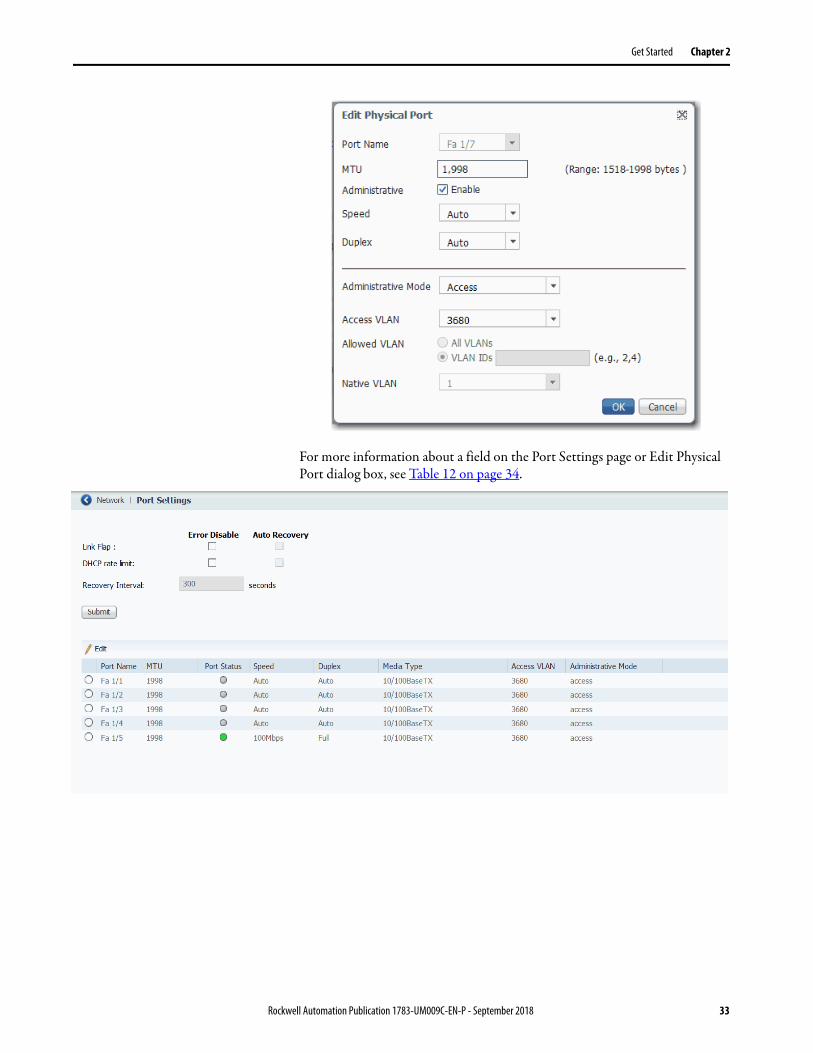
Get Started Chapter 2
For more information about a field on the Port Settings page or Edit Physical Port dialog box, see Table 12 on page 34.
Rockwell Automation Publication 1783-UM009C-EN-P - September 2018 33
Chapter 2 Get Started
Table 12 - Port Settings
Field Description
Port Name Displays the port type (Fa for Fast Ethernet) and number.
MTU The Maximum Transmission Unit (MTU) of the port.The range is 1518…1998 bytes. The default is 1998.MTU sizes larger than 1518 are jumbo frames.
Administrative (Appears only on the Edit Physical Port dialog box). Indicates whether the port is enabled or disabled:• Checked—The port is enabled.• Cleared—The port is disabled.By default, all ports are enabled.
Port Status (Appears only on the Port Settings page; not editable). The state of the switch port:• Green—Link is up.• Gray—No link or not connected. • Brown—Link is administratively shut down.
Speed The operating speed of the switch port:• 10 Mbps• 100 Mbps• Auto—Enables a connected device to negotiate the link speed.The default speed is Auto.
Duplex The Duplex mode of the switch port:• Auto (autonegotiation)—The connected device can negotiate the duplex setting with the switch. If the port is not connected or has not completed
negotiation, the status is Auto. • Full (Full-duplex mode)—Both devices can send data simultaneously.• Half (Half-duplex mode) —The connected device must alternate sending or receiving data. Both devices cannot send data simultaneously.The default is Duplex mode is Auto.We recommend that you use the default so that the duplex setting on the switch port automatically matches the setting on the connected device. Change the Duplex mode on the switch port if the connected device requires a specific mode. An example of when to change this setting is during troubleshooting. If you are troubleshooting a connectivity problem, you can change this setting to verify if the switch port and connected device have a duplex mismatch.
Administrative Mode The administrative mode of the port:• Access—The interface is in permanent non-trunk mode and negotiates to convert the neighboring link into a non-trunk link even if the
neighboring interface is a trunk interface. If you choose this option, also choose an Access VLAN. Access ports have the following characteristics: – Member of exactly one VLAN (the Access VLAN). The Access VLAN is 1 by default.– Accepts untagged frames only.– Discards all frames that are not classified to the Access VLAN.– On egress, all frames are transmitted untagged.
• Trunk—The interface is in permanent trunk mode and negotiates to convert the neighboring link into a trunk link even if the neighboring interface is not a trunk interface. If you choose this option, also choose whether to allow All VLANs or specified VLAN IDs. Trunk ports have the following characteristics:– By default, a trunk port is member of all VLANs (1…4094).– Limit the VLANs that a trunk port is a member of by using Allowed VLANs.– Frames that are classified to a VLAN that the port is not a member of are discarded.– By default, all frames except frames that are classified to the Port VLAN (the Native VLAN) get tagged on egress. Frames that are classified to the
Port VLAN do not get C-tagged on egress.– Egress can be changed to tag all frames, in which case only tagged frames are accepted on ingress.
• Hybrid—Similar to a trunk port, with the default configuration being VLAN tag unaware. The default administrative mode is Access.
Access VLAN The VLAN that an interface belongs to and carries traffic for, when the link is configured as or is acting as a nontrunking interface.
Allowed VLAN (Appears only on the Edit Physical Port dialog box). The VLAN or VLANs for which the interface handles traffic when the link is configured as or is dynamically acting as a trunking interface.To allow traffic on all available VLANs, click All VLANs.To limit traffic to specific VLANs, click VLAN IDs and enter the VLAN numbers.
Native VLAN (Appears only on the Edit Physical Port dialog box). The VLAN that transports untagged packets.
34 Rockwell Automation Publication 1783-UM009C-EN-P - September 2018

Get Started Chapter 2
Configuration in the Studio 5000 Environment
You can manage the switch by using the Logix Designer application in the Studio 5000® environment. The Logix Designer application is IEC 61131-3 compliant and offers relay ladder, structured text, Function Block Diagram, and sequential function chart editors for you to develop application programs.
To add the switch to a controller project in the Logix Designer application, follow these steps.
1. Open the project file for the controller to monitor the switch.
2. Right-click Ethernet and choose New Module.
3. On the Select Module Type dialog box, select the switch and click Create.
If you do not see the switch on the list, you can obtain the AOP from the Rockwell Automation support website:
http://www.rockwellautomation.com/support/
IMPORTANT These steps are required before you can go online to configure and monitor the switch. You must be online to view and configure most switch parameters in the Logix Designer application.
Rockwell Automation Publication 1783-UM009C-EN-P - September 2018 35

Chapter 2 Get Started
General Properties
To configure general properties, follow these steps.
1. In the navigation pane, click General.
2. Complete the fields, and then click Apply.
IMPORTANT The IP address and host name must match the values that you used during Express Setup. On the Module Properties dialog box, you can choose either an IP address or host name.
Table 13 - General Fields
Field Description
Name Enter a name to identify the switch.
Description Enter a description for the switch.
Ethernet Address Displays the IP address or host name for the switch that was specified during Express Setup.• Private Network—The IP address of your private network.• IP Address—The IP address that was specified during Express Setup.• Host Name—The host name that was specified during Express Setup. The host name
requires that you have a DNS server that is configured on the network for the Ethernet interface module of the controller.
36 Rockwell Automation Publication 1783-UM009C-EN-P - September 2018

Get Started Chapter 2
3. In the Module Definition area, click Change.
4. On the Module Definition dialog box, complete the fields and click OK.
Table 14 - Module Definition Fields
Field Description
Revision The major and minor revision of the switch:• Major revision: 1…128• Minor revision: 1…255
Electronic Keying Choose one of the following:• Compatible Module (default)• Exact Match• Disable Keying
Connection Choose one of the following:• Input Data (default): Enables only an input data connection.• Data: Enables an input and output data connection. ATTENTION: This selection enables output tags, which can disable ports and interrupt connections to and through the switch. You can disable a switch port by setting the corresponding bit in the output tag. The output bits are applied every time that the switch receives the output data from the controller when the controller is in Run mode. When the controller is in Program mode, the output bits are not applied.If the corresponding output bit is 0, the port is enabled. If you enable or disable a port by using Device Manager, the port setting is overridden by the output bits from the controller on the next cyclic update of the I/O connection. The output bits always take precedence.
Data Connection Password (Data connections only). Enter the password for accessing the switch. Enter a password within these guidelines:• Must be at least eight alphanumeric characters long • Must contain an uppercase character, a lowercase character, a special character such as @$!%*+=_?&, and a number• Is case-sensitive• Cannot contain a tab, nor space at the beginning or end
Rockwell Automation Publication 1783-UM009C-EN-P - September 2018 37

Chapter 2 Get Started
Connection Properties
To configure connection properties, follow these steps.
1. In the navigation pane, click Connection.
2. Complete the fields, and then click Apply.
Table 15 - Connection Fields
Field Description
Requested Packet Interval (RPI) Enter the period in milliseconds at which data updates over a connection. For example, an input module sends data to a controller at the RPI that you assign to the module.Valid range: 300…5000 ms
Inhibit Module To disable communication between the controller and the switch, check Inhibit Module.Clear Inhibit Module to restore communication.
Major Fault on Controller If Connection Fails While in Run mode To have the controller create a major fault if connection fails in Run mode, check the checkbox.
Use Unicast Connections over EtherNet/IP To use Unicast connections with the EtherNet/IP network, check the checkbox.
Module Fault Displays the fault code from the controller and the text that indicates the module fault has occurred.
38 Rockwell Automation Publication 1783-UM009C-EN-P - September 2018

Get Started Chapter 2
Switch Configuration
On the Switch Configuration view, you can do the following:• Change switch IP settings• Enter contact geographic location information for the switch• View the management VLAN for the switch
To configure switch IP and administrative settings, follow these steps.
1. In the navigation pane, click Switch Configuration.
2. Complete the fields that are described in Table 16 on page 40.
3. Click Set.
Rockwell Automation Publication 1783-UM009C-EN-P - September 2018 39

Chapter 2 Get Started
Table 16 - Switch Configuration Fields
Field Description
Internet Protocol (IP) Settings Click the method to use for assigning the switch an IP address:• Manually Configure IP settings (default)—The switch uses a manually assigned, static IP address.
If you manually assign the IP address of the switch and your network uses a DHCP server, the IP address cannot be within the range of addresses that the DHCP server assigns. Otherwise, IP address conflicts can occur between the switch and another device.
• Obtain IP settings automatically through DHCP—A Dynamic Host Configuration Protocol (DHCP) server automatically assigns the switch an IP address, subnet mask, and default gateway.Unless restarted, the switch continues to use the DHCP-assigned information.
We recommend that you manually assign the IP address for the switch. You can then use the same IP address whenever you want to access the switch.
Physical Module IP Address Displays the IP address that is assigned to the switch by the DHCP server during Express Setup. This value must match the IP address on the General view. If you change the assigned IP address, make sure that the new IP address is not assigned to another device in your network. The IP address and the default gateway cannot be the same.IMPORTANT: If you reconfigure your switch with another IP address, you can lose communication with the switch when you click Set. To correct this problem, you must return to the Express Setup and General view, set the new IP address, and download to the controller.
Subnet Mask Displays the IP address that is assigned to the switch by the DHCP server during Express Setup. The subnet mask is the network address that identifies the subnetwork (subnet) to which the switch belongs. Subnets are used to segment the devices in a network into smaller groups. The subnet mask is a 32-bit number. Set each octet between 0…255. The default is 255.255.255.0.
Gateway Address Displays the gateway address that is assigned to the switch by the DHCP server during Express Setup. A gateway is a router or a dedicated networkdevice that enables the switch to communicate with devices in other networks or subnetworks. The default gateway IP address must be part of the same subnet as the switch IP address. The switch IP address and the default gateway IP address cannot be the same.If all of your devices are in the same network and a default gateway is not used, you do not need to enter an IP address in this field. This field is enabled only if the IP assignment mode is Static. If your network management station and the switch are in different networks or subnetworks, you must specify a default gateway. Otherwise, the switch and your network management station cannot communicate with each other.IMPORTANT: Communication is disrupted when you change the gateway (IP) address.
Primary DNS Server Address (Required for DNS addressing). Enter the addresses to identify any DNS servers in the network. You must configure a DNS server if you specify a domain name or a host name. The DNS server converts the domain name or host name to an IP address that the network uses.Secondary DNS Server Address
Domain Name (Required for DNS addressing). Enter a domain name to identify the domain in which the switch resides. A domain name is part of a text address. The full text address of a module is host_name.domain_name. The domain name has a 48-character limit. If you specify a DNS server, you must enter a domain name.
Host Name (Required for DNS addressing). Enter a host name to identify the host for the switch. A host name is part of a text address. The full text address of a module is host_name.domain_name.
Contact Enter contact information for the switch, up to 200 characters. The contact information can include alphanumeric and special characters (dash and comma) and a carriage return.
Geographic Location Enter a geographic location of the switch, up to 200 characters. The geographic location can include alphanumeric and special characters (dash and comma) and a carriage return.
Management Interface VLAN Displays the VLAN through which the switch is managed. The management VLAN is the broadcast domain through which management traffic is sent between specific users or device. It also provides secure administrative access to all devices in the network.IMPORTANT: Be sure that the switch and your network management station are in the same VLAN. Otherwise, you lose management connectivity to the switch.
40 Rockwell Automation Publication 1783-UM009C-EN-P - September 2018

Get Started Chapter 2
Port Configuration
Configure ports to specify how data is sent and received between the switch and a connected device.
To configure ports, follow these steps.
1. In the navigation pane, click Port Configuration.
2. Complete the fields, and click Set.
Table 17 - Port Configuration Fields
Field Description
Port Displays the port type (Fa for Fast Ethernet) and number.
Enable To enable the port, check Enable.To disable the port manually, clear the Enable checkbox. If the port is not in use and is not attached to a device, we recommend that you disable the port. You can troubleshoot a suspected unauthorized connection by manually disabling the port.
Auto-Negotiate If you want the port and end-device to auto-negotiate the link speed and Duplex mode, check Auto-Negotiate.To specify the port speed and Duplex mode manually, clear the Auto-Negotiate checkbox.We recommend that you use the default (auto-negotiate) so that the speed and duplex settings on the switch port match the setting on the connected device. Change the switch port speed and duplex if the connected device requires a specific speed and duplex. If you set the speed and duplex for the switch port, the connected device must be configured for the same speed and duplex and not set to auto-negotiate. Otherwise, a speed/duplex mismatch occurs.
Speed Choose the operating speed of the port: • 10 Mbps• 100 Mbps
Duplex Choose one of these Duplex modes: • Half-duplex—Both devices cannot send data simultaneously.• Full-duplex—Both devices can send data simultaneously.
Rockwell Automation Publication 1783-UM009C-EN-P - September 2018 41

Chapter 2 Get Started
User Administration in Device Manager
From the Admin menu, under Device Management, choose Users.
Users are validated based on the Authentication, Authorization, and Accounting (AAA) method chosen from the pull-down menu. Click Submit after choosing the desired method.
For server configuration information, see Terminal Access Controller Access Control System Plus/Remote Authentication Dial-In User Service (TACACS+/RADIUS) on page 99.
You can add, edit, or delete users for the switch:
• To add a user, click Add. Complete the fields that are described in Table 19 on page 43 and click OK.
• To edit a user, click the radio button next to the user and click Edit. Edit the fields that are described in Table 19 on page 43 and click OK.
• To delete a user, click the radio button next to the user and click Delete.
Table 18 - AAA Method Pull-down Menu
Field Description
Local Use the local user database that is configured on the device. Local is the default setting.
Tacacs - > Local Use the TACACS server. Use the local user database if the TACACS server is unavailable.
Radius - > Local Use the RADIUS server. Use the local user database if the RADIUS server is unavailable.
42 Rockwell Automation Publication 1783-UM009C-EN-P - September 2018

Get Started Chapter 2
Table 19 - Add/Edit User Fields
Field Description
Name Enter a unique user name. The user name cannot contain spaces.
Privilege Choose the level of access for the user:• Admin—Users can view and change all switch parameters.• ReadOnly—Users can only view switch status and monitoring information.
Users cannot view configuration information, view administration information, or make changes to the switch.
Password Enter the password that is required for access with this user name.Enter a password within these guidelines:• Must be at least eight alphanumeric characters long • Must contain an uppercase character, a lowercase character, a special character
such as @$!%*+=_?&, and a number• Is case-sensitive• Cannot contain a tab, nor space at the beginning or end
Confirm Password
Rockwell Automation Publication 1783-UM009C-EN-P - September 2018 43

Chapter 2 Get Started
Configuration Files When any changes are made to the switch configuration, the changes immediately take effect in the running configuration file. Device Manager and the Logix Designer application automatically save changes to internal memory to be retained for the next power-on cycle. You can move configuration files to or from the switch.
Manage Configuration Files in Device Manager
Device Manager uses Trivial File Transfer Protocol (TFTP) or Hypertext Transfer Protocol (HTTP) for the file transfer.
The following configuration files are available for transfer:
• running-config—Stores the running configuration of the switch. Available for upload and download.
• startup-config—Stores the start-up configuration of the switch. Available for download only.
Upload a File
To upload the running-config file to the switch, follow these steps.
1. From the Admin menu, under File Management, choose Load/Save.
2. If the file is on your local computer, click Browse, select the file, and then click Upload.
or
If the file is on a remote TFTP server, in the TFTP Address and File location fields, enter the IP address of the server and the path to the file. Click Upload.
The configuration file must be named running-config to replace the existing file.
44 Rockwell Automation Publication 1783-UM009C-EN-P - September 2018

Get Started Chapter 2
Download a File
To download a running-config or startup-config file, follow these steps.
1. From the Admin menu, under File Management, choose Load/Save.
2. If the file is on your local computer, from the Select a configuration file pull-down menu, choose the configuration file to download, and then click Download.
or
If the file is on a remote TFTP server, in the TFTP Address and File location fields, enter the IP address of the server and the path to the file. Click Download.
IMPORTANT After you have completed this download, you must save the running configuration without restarting the switch as shown on page 132. When you save the running configuration without restarting the switch, you maintain the configuration through the next power cycle.
Rockwell Automation Publication 1783-UM009C-EN-P - September 2018 45

Chapter 2 Get Started
Manage Configuration Files in the Logix Designer Application
In the Logix Designer application, you can save and restore the following two configuration files:
• Text file with switch configuration parameters (config.text)
• Binary file with VLAN information (vlan.dat)
Be prepared to enter a valid switch password. Enter a password within these guidelines:
• Must be at least eight alphanumeric characters long
• Must contain an uppercase character, a lowercase character, a special character such as @$!%*+=_?&, and a number
• Is case-sensitive
• Cannot contain a tab, nor space at the beginning or end
To save and restore configuration files, follow these steps.
1. In the navigation pane, click Save/Restore:• To replace the configuration files in the controller project with the
configuration files on the switch, click Upload.• To replace the configuration files on the switch with the
configuration files in the controller project, click Download.• To restore the configuration files in the controller project with files
on your local computer, click Import.• To save the configuration files in the controller project to your local
computer, click Export.
2. Click OK.I
46 Rockwell Automation Publication 1783-UM009C-EN-P - September 2018

Get Started Chapter 2
Rockwell Automation Publication 1783-UM009C-EN-P - September 2018 47

Chapter 2 Get Started
Software Updates You can download the latest software for all switches fromhttp://www.rockwellautomation.com.
In Device Manager, you can do the following with the firmware file:
• Use TFTP to transfer the file to the switch
• Use HTTP to download the file to your personal computer or a network drive, and then select it for the update.
• Swap to a backup image file.
The Software Update page shows the following information:
• Active Image—Version of the software that is currently installed on the switch.
• Backup Image—Version of the backup image file.
When the device ships from the factory, the backup image is the same as the installed image. When you upgrade the software, the previously installed image becomes the backup.
Apply a Software Update
To apply the latest software (.bin file) to the switch, follow these steps.
1. From the Admin menu, under File Management, choose Software Update.
2. If the file is on your local computer, click Browse, select the file, and then click Update.
or
If the file is on a remote TFTP server, in the TFTP Address and Image location fields, enter the IP address of the TFTP server and path to the file location. Click Update.
The Software Update page displays the progress of the software update.
IMPORTANT After the update completes successfully as indicated by a message notification, we recommend that you clear your browser cache and restart Device Manager in a new browser session.
48 Rockwell Automation Publication 1783-UM009C-EN-P - September 2018

Get Started Chapter 2
Apply a Backup Image
To swap to a backup image, follow these steps.
1. From the Admin menu, under File Management, choose Software Update.
2. Check Swap to back-up image.
3. Click Submit.
A message notifies you of the swap, and the device reloads.
Rockwell Automation Publication 1783-UM009C-EN-P - September 2018 49

Chapter 2 Get Started
Access Management in Device Manager
If a Technical Support representative requires remote access to the switch via the command-line interface (CLI), you must configure access to the switch following these steps:
1. From the Admin menu, under Device Management, choose Access Management.
2. To enable remote access to the switch via the CLI, check Enable SSH.
3. Click Submit.
50 Rockwell Automation Publication 1783-UM009C-EN-P - September 2018

Chapter 3
Configure Switch Features
This chapter describes software features that you can configure in Device Manager, the Studio 5000 Logix Designer® application, or both.
Topic Page
802.1X Authentication 52
Alarms 53
Dynamic Host Configuration Protocol (DHCP) 56
EtherChannels 66
Internet Group Management Protocol (IGMP) Snooping with Querier 71
Port Mirroring 73
Port Security 74
Quality of Service (QoS) 78
Simple Network Management Protocol (SNMP) 79
Smartports 89
Spanning Tree Protocol (STP) 92
Storm Control 98
Terminal Access Controller Access Control System Plus/Remote Authentication Dial-In User Service (TACACS+/RADIUS)
99
Virtual Local Area Networks (VLANs) 100
Rockwell Automation Publication 1783-UM009C-EN-P - September 2018 51

Chapter 3 Configure Switch Features
802.1X Authentication IEEE 802.1X enables port-based access control using authentication. An 802.1X-enabled port can be dynamically enabled or disabled based on the identity of the client that connects to it.
Before authentication, the identity of the client is unknown and traffic is blocked. After authentication, the identity of the client is known and traffic from that endpoint is permitted. The switch performs source MAC filtering to help ensure that only the authenticated client is permitted to send traffic.
802.1X includes these components:
• Supplicant—A client on the endpoint that submits credentials for authentication.
• Authenticator—The network access device that relays the credentials of the supplicant to the authentication server.
• Authentication server—A server that validates the credentials and determines what level of network access the client receives. See RADIUS server information on page 99.
Use the 802.1X page to configure 802.1X port-based authentication on the switch.
52 Rockwell Automation Publication 1783-UM009C-EN-P - September 2018

Configure Switch Features Chapter 3
To modify the 802.1X administrative state for an individual port, select the row in the Dot1x Port Table. See Table 21.
Alarms In Device Manager, you can configure alarms to monitor the following types of temperatures:
• Switch temperature
IMPORTANT You must configure the RADIUS server before configuring 802.1X authentication. See Table 50 on page 100.
Table 20 - Global Settings to Configure 802.1X Authentication
Field Description
Enable 802.1X Choose one of the following: • enable—Globally activates 802.1X authentication on the switch. • disable—Globally deactivates 802.1X authentication on the switch. All physical interfaces are permitted to forward frames.
Enable Reauthentication Choose one of the following: • enable—Successfully authenticated clients can be reauthenticated after the interval specified by the Reauthentication Period. • disable—Reauthentication is not activated.Reauthentication for 802.1X-enabled interfaces can be used to detect if a new device is plugged into a switch port or if a supplicant is no longer attached. For MAC-based ports, reauthentication is only useful if the RADIUS server configuration has changed. Reauthentication does not involve communication between the switch and the client device, and therefore does not imply that a client is still present on a port.
EAPOL Timeout The time limit for retransmission of Request Identity EAPOL frames. EAPOL timeout is not applicable for MAC-based ports.Valid range: 1…65535 secondsDefault: 30
Hold Time The wait time before attempting to reauthenticate after reauthentication failed for a client.Valid range: 10…1000000 secondsDefault: 10
Max Reauth Count The maximum number of retransmissions to Request Identity for EAPOL frame.Valid range: 1…255Default: 2
Submit Click when your changes to Global Configuration fields are complete.
Table 21 - Modify Administrative State Per Port
Field Description
Interface The number of the switch port, including port type (such as Fa for Fast Ethernet), and the specific port number. For example, Fa1/1 is Fast Ethernet port 1 on the switch.
Dot1x Control State Choose one of the following administrative modes:• Force Authorized—802.1X authentication is disabled. The port is in the authorized state and grants access to all clients. Force
Authorized is the default setting.• Force Unauthorized—The port is in the unauthorized state and all denies access to all clients. • MAC Base Auth—This mode is used for 802.1X-unaware devices. The switch authenticates on behalf of the client, using the client
MAC address as the username and password for the Microsoft Extensible Authentication Protocol-Message Digest 5 (EAP-MD5) method.
• Single 802.1X—The authentication server authorizes only one 802.1X-aware client. A client that is not 802.1X-aware is denied access. If the client leaves or is replaced with another, the device changes the port link state to down and the port enters the unauthorized state.
The administrative mode cannot be changed to anything other than Force Authorized when Spanning Tree is enabled on the interface. See Spanning Tree Protocol (STP) on page 92.
Dot1x State The 802.1X status of the port (enabled or disabled). This field is not editable.
Re-Authenticate Select a row or multiple rows in the Port Security Table and click Re-Authenticate to force a new authentication.
Rockwell Automation Publication 1783-UM009C-EN-P - September 2018 53

Chapter 3 Configure Switch Features
• Junction temperature
You can define maximum, minimum, and critical temperatures parameters. If the switch detects a temperature condition that does not match the defined temperature parameters, an alarm is triggered.
When an alarm is triggered, it appears in the system log and the Alarms area in the lower-right corner of the Device Manager window. The severity of the alarms you configure on the Alarms Settings page is always Major.
To configure alarm settings, follow these steps.
1. From the Configure menu, under Alarms, choose Alarm Settings.
2. In the Alarm Settings table, click the alarm name to configure.
3. Complete the fields that are described in Table 22 on page 55.
4. Click Save.
Alarms
54 Rockwell Automation Publication 1783-UM009C-EN-P - September 2018

Configure Switch Features Chapter 3
Table 22 - Alarm Settings
Alarm Name Field Description
Switch Temperature Enable Alarm To enable the alarm, check Enable Alarm. To disable the alarm, clear the Enable Alarm checkbox.By default, the alarm for switch temperature is enabled.
Thresholds (MIN) in °C Enter a minimum temperature threshold in degrees Celsius. If the temperature falls below the minimum threshold value, the switch triggers an alarm. Valid range: -40…+125 °C (-40…+257 °F) Default: -20 °C (-4 °F)
Thresholds (MAX) in °C Enter a maximum temperature threshold in degrees Celsius. If the temperature exceeds the maximum threshold value, the switch triggers an alarm. Valid range: -40…+125 °C (-40…+257 °F)Default: 85 °C (185 °F)
Thresholds (CRIT) in °C Enter a critical temperature threshold in degrees Celsius. If the temperature exceeds the critical threshold value, the switch triggers an alarm. Valid range: 90…150 °C (194…302 °F)Default: 95 °C (203 °F)
Junction Temperature Enable Alarm To enable the alarm, check Enable Alarm. To disable the alarm, clear the Enable Alarm checkbox.By default, the alarm for junction temperature is disabled.
Thresholds (MIN) in °C Enter a minimum temperature threshold in degrees Celsius. If the temperature falls below the minimum threshold value, the switch triggers an alarm. Valid range: -40…+125 °C (-40…+257 °F)Default: -40 °C (-40 °F)
Thresholds (MAX) in °C Enter a maximum temperature threshold in degrees Celsius. If the temperature exceeds the maximum threshold value, the switch triggers an alarm. Valid range: -40…+125 °C (-40…+257 °F)Default: 110 °C (230 °F)
Thresholds (CRIT) in °C Enter a critical temperature threshold in degrees Celsius. If the temperature exceeds the critical threshold value, the switch triggers an alarm. Valid range: 90…150 °C (194…302 °F)Default: 120 °C (248 °F)
Rockwell Automation Publication 1783-UM009C-EN-P - September 2018 55

Chapter 3 Configure Switch Features
Dynamic Host Configuration Protocol (DHCP)
The switch can operate as a DHCP server by automatically assigning IP addresses to connected devices.
Every device in an IP-based network must have a unique IP address. DHCP assigns IP address information from a pool of available addresses to newly connected devices (DHCP clients) in the network. If a device leaves and then rejoins the network, the device receives the next available IP address, which is not necessarily the same address that the device had before.
To configure DHCP server settings and the IP address pools in Device Manager, click the Global Settings tab.
DHCP Persistence
Use the DHCP persistence feature to assign a specific, reserved IP address to each port. The device that is connected to that port always receives the same IP address regardless of the MAC address of the connected device. DHCP persistence is useful in networks that you configure in advance, where dependencies on the exact IP addresses of some devices exist. Use DHCP persistence when the attached device has a specific role to play and when other devices know its IP address. If the device is replaced, the replacement device is assigned the same IP address, and the other devices in the network require no reconfiguration.
DHCP persistence works with only one device that is connected to each port configured for the feature.
When the DHCP persistence feature is enabled, the switch acts as a DHCP server for other devices on the same subnet, including devices that are connected to other switches. If the switch receives a DHCP request, it responds with any unassigned IP addresses in its pool. To keep the switch from responding when it receives a request, check the Reserved Only box on the DHCP page, Global Settings tab.
When DHCP persistence is enabled and a DHCP request is made from a connected device on that port, the switch assigns the IP address for that port. The switch also broadcasts the DHCP request to the remainder of the network. If another DHCP server with available addresses is on the network and receives this request, it can try to respond. The response can override the initial IP address that the switch assigns depending on the end device (takes first IP address response or the last). To keep the IP address from being overridden, enable DHCP Snooping on the appropriate VLAN. DHCP snooping blocks the broadcast of this DHCP request, so that no other server, including another Stratix switch with DHCP persistence enabled, responds.
If you are using DHCP persistence, we recommend that you initially assign static IP addresses to end devices. If an end device fails and is replaced, the
IMPORTANT To make sure DHCP persistence works correctly, follow the application rules.
56 Rockwell Automation Publication 1783-UM009C-EN-P - September 2018

Configure Switch Features Chapter 3
DHCP persistence feature assigns an IP address from the DHCP persistence table. We recommend that you reassign a static IP address to the replaced device.
The following figure and table illustrate DHCP persistence behavior.
To configure DHCP persistence for individual interfaces, click the DHCP Port Configurations tab. See Table 26 on page 61.
Configure DHCP Persistence Via Device Manager
To configure DHCP persistence, complete this process.
1. Enable the DHCP server.
2. Configure the IP address pool.
3. Assign an IP address to a switch port.
FA1 FA2 FA3 FA7 FA4 FA5 FA6 FA8
Switch 1 Switch 2
Table 23 - DHCP Persistence Behavior
If Then
• Switch 1 has ports FA1…FA3 in its persistence table• Switch 2 has ports FA4, FA5, FA6, and FA8 in its DHCP Persistence
table• Reserve Only is not selected and DHCP Snooping is off
A new device that is connected to switch 1 FA1 receives an IP address from the switch 1 in the persistence table. A broadcast request is also sent across the network. Switch 2 responds if there is an unassigned address in its pool. The response can override the assignment that is made by switch 1.
• Switch 1 has ports FA1…FA3 in its persistence table• Switch 2 has ports FA4, FA5, FA6, and FA8 in its DHCP Persistence
table• Reserve Only is selected in both switches and DHCP Snooping is off
A new device that is connected to switch 1 FA1 receives an IP address from the switch 1 in the persistence table. A broadcast request is also sent across the network. Switch 2 does not respond to the request. If the device is connected to FA7 of switch 1, it does not receive an IP address from the switch pool because it is not defined in the table. Also, unused addresses in the pool are blocked.
• Switch 1 has ports FA1…FA3 in its persistence table• Switch 2 has ports FA4, FA5, FA6, and FA8 in its DHCP Persistence
table• Reserve Only is selected in switch 1 and DHCP snooping is off, but
not switch 2 when DHCP Snooping is off
A new device is connected to FA1 receives an IP address from the persistence table. A broadcast request is also sent across the network. Switch 2 does not respond to the request. In addition, a device that is connected to FA4 receives an IP address from the switch 2 in the persistence table. A broadcast request is sent out, and switch 1 responds with an unused IP address from its pool. The response can override the assigned port.
• Switch 1 has ports FA1…FA3 in its persistence table• Switch 2 has ports FA4, FA5, FA6, and FA8 in its DHCP Persistence
table• DHCP Snooping is selected• Reserved Only is checked
A new device that is connected to switch 1 FA1 receives an IP address from the Switch 1 persistence table. A broadcast request is not sent across the network, so Switch 2 does not respond. If a device is connected to FA7 of Switch 1, it does not receive an IP address from the switch pool because it is not defined in the table. Also, unused addresses in the pool are blocked.
• Switch 1 has ports FA1…FA3 in its persistence table• Switch 2 has ports FA4, FA5, FA6, and FA8 in its DHCP Persistence
table• DHCP Snooping is selected• Reserved Only is not checked
A new device that is connected to switch 1 FA1 receives an IP address from the Switch 1 persistence table. A broadcast request is not sent across the network, therefore Switch 2 does not respond. If a device is connected to FA7 (not defined in the DHCP Persistence table) of Switch 1, it receives an unassigned IP address from the switch 1 pool.
Rockwell Automation Publication 1783-UM009C-EN-P - September 2018 57

Chapter 3 Configure Switch Features
Enable the DHCP Server
1. From the Configure menu, choose DHCP.
2. Click Enable DHCP.
3. Click Submit.
Configure the DHCP IP Address Pool
Once DHCP is enabled, you can create the DHCP address pool.
1. From the Configure menu, choose DHCP.
2. Click Add.
3. Complete the fields and click OK.
58 Rockwell Automation Publication 1783-UM009C-EN-P - September 2018

Configure Switch Features Chapter 3
Table 24 - DHCP Pool Table Add Fields
Field Description
DHCP Pool Name The name of the DHCP IP address pool that is configured on the switch. The name can have up to 31 alphanumeric characters. The name cannot contain a ? or a tab. This field is required. A DHCP IP address pool is a range (or pool) of available IP addresses that the switch can assign to connected devices.
DHCP Pool Network The subnetwork IP address of the DHCP IP address pool. The format is a 32-bit numeric address that is written as four numbers that are separated by periods. Each number can be from 0…255. This field is required.
Subnet Mask The network address that identifies the subnetwork (subnet) of the DHCP IP address pool. Subnets segment the devices in a network into smaller groups. The default is 255.255.255.0. This field is required.
Starting IP The starting IP address that defines the range of addresses in the DHCP IP address pool. The format is a 32-bit numeric address that is written as four numbers that are separated by periods. Each number can be from 0…255. Be sure that none of the IP addresses that you assign are being used by another device in your network. This field is required.
Ending IP The ending IP address that defines the range of addresses in the DHCP IP address pool. The format is a 32-bit numeric address that is written as four numbers that are separated by periods. Each number can be from 0…255. Make sure that none of the IP address you assign are being used by other devices in your network. This field is required.
Default Router The default router IP address for the DHCP client that uses this server. The format is a 32-bit numeric address that is written as four numbers that are separated by periods. Each number can be from 0… 255.
Domain Name The domain name for the DHCP client. The name can have up to 31 alphanumeric characters. The name cannot contain a ? or a tab.
DNS Server The IP addresses of the domain name system (DNS) IP servers available to a DHCP client. The format is a 32-bit numeric address that is written as four numbers that are separated by periods. Each number can be from 0…255.
[Lease Length] The duration of the lease for an IP address that is assigned to a DHCP client. Click one of the following: • Never Expires • User Defined If you click User Defined, enter the duration of the lease in the numbers of days, hours, and minutes. This lease length is used for all assignments.
Rockwell Automation Publication 1783-UM009C-EN-P - September 2018 59
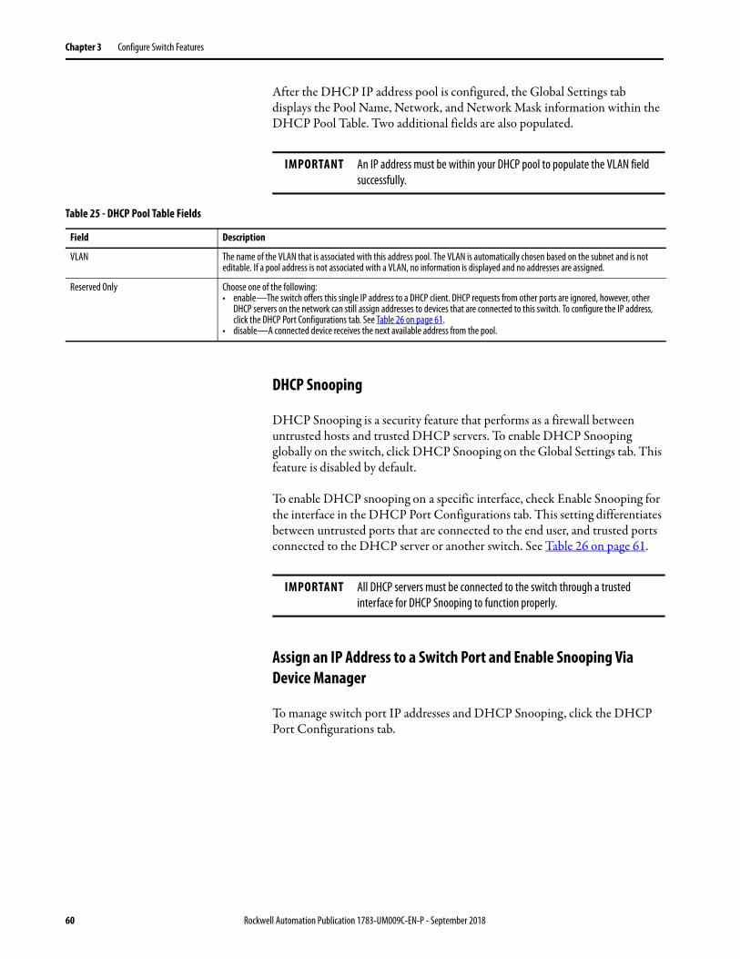
Chapter 3 Configure Switch Features
After the DHCP IP address pool is configured, the Global Settings tab displays the Pool Name, Network, and Network Mask information within the DHCP Pool Table. Two additional fields are also populated.
DHCP Snooping
DHCP Snooping is a security feature that performs as a firewall between untrusted hosts and trusted DHCP servers. To enable DHCP Snooping globally on the switch, click DHCP Snooping on the Global Settings tab. This feature is disabled by default.
To enable DHCP snooping on a specific interface, check Enable Snooping for the interface in the DHCP Port Configurations tab. This setting differentiates between untrusted ports that are connected to the end user, and trusted ports connected to the DHCP server or another switch. See Table 26 on page 61.
Assign an IP Address to a Switch Port and Enable Snooping Via Device Manager
To manage switch port IP addresses and DHCP Snooping, click the DHCP Port Configurations tab.
IMPORTANT An IP address must be within your DHCP pool to populate the VLAN field successfully.
Table 25 - DHCP Pool Table Fields
Field Description
VLAN The name of the VLAN that is associated with this address pool. The VLAN is automatically chosen based on the subnet and is not editable. If a pool address is not associated with a VLAN, no information is displayed and no addresses are assigned.
Reserved Only Choose one of the following: • enable—The switch offers this single IP address to a DHCP client. DHCP requests from other ports are ignored, however, other
DHCP servers on the network can still assign addresses to devices that are connected to this switch. To configure the IP address, click the DHCP Port Configurations tab. See Table 26 on page 61.
• disable—A connected device receives the next available address from the pool.
IMPORTANT All DHCP servers must be connected to the switch through a trusted interface for DHCP Snooping to function properly.
60 Rockwell Automation Publication 1783-UM009C-EN-P - September 2018

Configure Switch Features Chapter 3
Bootstrap Protocol (BOOTP)
The switch also supports BOOTP for the assignment of IP addresses. When the DHCP server is enabled and a client sends a BOOTP request, the server responds with a BOOTP response that is based on the DHCP pool configuration. DHCP options are not supported in the BOOTP process. The switch does not distinguish between BOOTP requests or DHCP requests when a reserved IP address is configured for an interface. To use BOOTP, you must enable DHCP; there are no BOOTP-specific settings to configure through Device Manager.
Table 26 - DHCP Port Configurations Fields
Field Description
Interface The number of the switch port, including port type (such as Fa for Fast Ethernet), and the specific port number. For example, Fa1/1 is Fast Ethernet port 1 on the switch.
Pool Name The name of the DHCP IP address pool that is configured on the switch.
Reserved IP Address The IP address that is assigned to the switch port. The IP address that you assign is reserved for the selected port and is not available for normal DHCP dynamic assignment. The IP address must be an address from the pool that is specified in the DHCP Pool Name field.
Enable Snooping Choose one of the following: • enable—Check Enable Snooping to configure the interface to transmit DHCP Discovery and Request messages to a DHCP Server.
Check Enable Snooping on the interface that is attached to an external DHCP server. • disable—Clear the Enable Snooping checkbox to receive DHCP Discovery and Request messages from a client. Leave Enable
Snooping disabled for all clients that request an IP Address from an external DHCP Server.
DHCP Rate Limit Set the rate of DHCP packets that are allowed through the port per second. If the number of packets exceeds this value, and Error Disable is selected for DHCP rate limit on the Port Settings page, the port is placed in the error-disabled state. Error disable is triggered on trusted ports with Enable Snooping enabled on relevant VLANs. For example, if the DHCP rate limit is set to 5, and six DHCP frames are received per second, the port enters the error-disabled state. The number of clients to receive an IP address before the port enters this state depends on the type of DHCP packets that are exchanged within that second. It is recommended you set the limit to 100 and above so that valid clients can receive an IP address. Range is 0 -500. Zero indicates that DHCP rate limit is not active.
Rockwell Automation Publication 1783-UM009C-EN-P - September 2018 61

Chapter 3 Configure Switch Features
Configure DHCP Persistence Via Logix Designer
To configure DHCP persistence, complete this process.
1. Configure the DHCP server.
2. Configure the DHCP IP address pool.
3. Assign an IP address to a switch port.
Configure the DHCP Server
1. In the navigation pane, click DHCP Pools.
2. Click Enable Dynamic Host Configuration Protocol (DHCP).
3. To enable DHCP snooping on the switch, click Enable DHCP Snooping.
DHCP snooping restricts the broadcast of DHCP requests beyond the connected switch. As a result, devices receive address assignments from only the connected switch. This option is available only on ports that are assigned to a VLAN.
To enable DHCP snooping on a specific VLAN, check DHCP Snooping for the specific VLAN in the DHCP pool table.
62 Rockwell Automation Publication 1783-UM009C-EN-P - September 2018

Configure Switch Features Chapter 3
Configure the DHCP IP Address Pool
Once DHCP is enabled, you can create the DHCP address pool.
1. In the navigation pane, click DHCP Pools.
2. Click New Pool.
3. Complete the fields as shown in Table 27 on page 64.
Rockwell Automation Publication 1783-UM009C-EN-P - September 2018 63

Chapter 3 Configure Switch Features
4. Click Set and Close.
Table 27 - Add/Edit DCHP Pool Definition Fields
Field Description
DHCP Pool Name The name of the DHCP IP address pool that is configured on the switch. The name can have up to 31 alphanumeric characters. The name cannot contain a ? or a tab. This field is required. A DHCP IP address pool is a range (or pool) of available IP addresses that the switch can assign to connected devices.
DHCP Pool Network The subnetwork IP address of the DHCP IP address pool. The format is a 32-bit numeric address that is written as four numbers that are separated by periods. Each number can be from 0…255. This field is required.
Subnet Mask The network address that identifies the subnetwork (subnet) of the DHCP IP address pool. Subnets segment the devices in a network into smaller groups. The default is 255.255.255.0. This field is required.
Default Gateway The default gateway IP address for the DHCP client. The format is a 32-bit numeric address that is written as four numbers that are separated by periods (for example, 255.255.255.255). Each number can be from 0… 255.
Domain Name The domain name for the DHCP client.
Starting IP Address The starting IP address that defines the range of addresses in the DHCP IP address pool. The format is a 32-bit numeric address that is written as four numbers that are separated by periods. Each number can be from 0…255. Be sure that none of the IP addresses that you assign are being used by another device in your network. This field is required.
Ending IP Address The ending IP address that defines the range of addresses in the DHCP IP address pool. The format is a 32-bit numeric address that is written as four numbers that are separated by periods. Each number can be from 0…255. Make sure that none of the IP address you assign are being used by other devices in your network. This field is required.
Use Preassigned Addresses Only If checked, IP addresses are assigned only when configured for specific ports on the DHCP Address Assignment view.
Enable DHCP Snooping for this Pool If checked, devices only receive address assignments from the connected switch.
Never ExpiresorCustom
The duration of the lease for an IP address that is assigned to a DHCP client. Click one of the following:• Never Expires• CustomIf you click Custom, enter the duration of the lease in the numbers of days, hours, and minutes. This lease length is used for all assignments.
Primary DNS Address The IP addresses of the primary domain name system (DNS) IP servers available to a DHCP client.
Secondary DNS Address The IP addresses of the secondary domain name system (DNS) IP servers available to a DHCP client.
Primary WINS Address The IP address of the primary Microsoft NetBIOS name server (WINS server) available to a DHCP client.
Secondary WINS Address The IP address of the secondary Microsoft NetBIOS name server (WINS server) available to a DHCP client.
64 Rockwell Automation Publication 1783-UM009C-EN-P - September 2018

Configure Switch Features Chapter 3
Assign an IP Address to a Switch Port
In the navigation pane, click DHCP Address Assignment.
You can assign a specific IP address to each port so that the device that is attached to a given port receives the same IP address.
Table 28 - DHCP Address Assignment Fields
Field Description
Port The number of the switch port, including port type (such as Fa for Fast Ethernet), and the specific port number. For example, Fa1/1 is Fast Ethernet port 1 on the switch.
Pool Displays the pool names from the DHCP IP address pool that corresponds to the instances available in the switch. If you delete all rows that contain pools on the DHCP Pool Display tab and click Refresh, the Pool field is blank.
IP Address Displays the IP address that is assigned to the switch port. The format is a 32-bit numeric address that is written as four numbers that are separated by periods (for example, 255.255.255.255). Each number can be from 0…255. The IP address that you assign is reserved for the selected port and is not available for normal DHCP dynamic assignment. The IP address must be an address from the pool that is specified in the DHCP Pool Name field.
Rockwell Automation Publication 1783-UM009C-EN-P - September 2018 65

Chapter 3 Configure Switch Features
EtherChannels An EtherChannel, or port group, is a group of two or more switch ports that are bundled into one logical link to create a higher bandwidth link between two switches. For example, four Fast Ethernet switch ports that are all configured to operate at 100 Mbps can be assigned to an EtherChannel to provide full-duplex bandwidth of up to 400 Mbps. If one of the ports in the EtherChannel becomes unavailable, traffic is carried over the remaining ports within the EtherChannel. The maximum number of channels that you can configure is half of the number of available ports. For example, for a five-port device you can configure two channels. You must have at least two ports in an EtherChannel, and the maximum number of ports in a channel is the maximum number of ports on the switch minus one.
All ports in an EtherChannel must have the same characteristics:
• All are configured with the same speed and duplex mode.
• The ports in an EtherChannel cannot already be in use in another EtherChannel.
• All ports are enabled. A disabled port in an EtherChannel is treated as a link failure, and its traffic is transferred to one of the remaining ports in the EtherChannel.
Figure 1 shows two EtherChannels. Two full-duplex 10/100 ports on Switches A and C create an EtherChannel with a bandwidth of up to 400 Mbps between both switches. Similarly, two full-duplex 10/100 ports on Switches B and D create an EtherChannel with a bandwidth of up to 400 Mbps between both switches.
If one of the ports in the EtherChannel becomes unavailable, traffic is sent through the remaining ports within the EtherChannel.
Figure 1 - EtherChannel Example
Table 29 on page 67 describes the modes that you can assign to an EtherChannel:
Servers
Switch A Switch B
Switch C Switch D
Network ManagementAccess
PointRouter with Firewall
WAN/Internet
Switch C
66 Rockwell Automation Publication 1783-UM009C-EN-P - September 2018

Configure Switch Features Chapter 3
Configure both ends of the EtherChannel in the same mode:
• When you configure one end of an EtherChannel in LACP mode, the system negotiates with the other end of the channel to determine the ports to become active. Incompatible ports are suspended. Instead of a suspended state, the local port is put into an independent state and continues to carry data traffic as any other single link. The port configuration does not change, but the port does not participate in the EtherChannel.
• When you configure an EtherChannel in Static mode, no negotiations take place. The switch forces all compatible ports to become active in the EtherChannel. The other end of the channel on the other switch must also be configured in the Static mode. Otherwise, packet loss can occur.
If a link within an EtherChannel fails, traffic previously carried over that failed link moves to the remaining links within the EtherChannel. If traps are enabled on the switch, a trap is sent for a failure that identifies the switch, the EtherChannel, and the failed link. Inbound broadcast and multicast packets on one link in an EtherChannel are blocked from returning on any other link of the EtherChannel.
You can configure EtherChannels in Device Manager or the Logix Designer application.
Table 29 - EtherChannel Modes
Mode Description
Static All ports join the EtherChannel, without negotiations. This mode can be useful if the remote device does not support the protocols that other modes require. The switches at both ends of the link must be configured in Static mode. In this mode, the system assigns a channel group number even if there is no connection to any device on the assigned ports.
Link Aggregation Control Protocol (LACP) (active) This mode enables LACP unconditionally. The port sends LACP packets to other ports to initiate negotiations to create EtherChannels. A port in active LACP mode can form an EtherChannel with another port that is in active or passive LACP mode. The ports must be configured for full-duplex. In this mode, the system assigns a channel group number only when a device is connected to create a physical channel.
Link Aggregation Control Protocol (LACP) (passive) This mode enables LACP only if an LACP device is detected at the other end of the link. The port responds to requests to create EtherChannels but does not initiate negotiations. The ports must be configured for full-duplex. In this mode, the system assigns a channel group number only when a device is connected to create a physical channel.
Rockwell Automation Publication 1783-UM009C-EN-P - September 2018 67

Chapter 3 Configure Switch Features
You can add, edit, or delete an EtherChannel:
• To add an EtherChannel, click Add. Complete the fields that are described in Table 31 and click OK.
• To edit an EtherChannel, click the radio button next to the EtherChannel and click Edit. Complete the fields that are described in Table 31 and click OK.
• To delete an EtherChannel, click the radio button next to the EtherChannel and click Delete.
.
Table 30 - EtherChannel Table Fields
Field Description
Channel Group Number A system-generated number to identify the EtherChannel. Valid values: 1 to the maximum number of EtherChannels, which is half of the number of available ports.
Channel Mode Determines how ports become active. With all modes except Static, negotiations occur to determine which ports become active. Incompatible ports are put into an independent state and continue to carry data traffic, but do not participate in the EtherChannel.IMPORTANT: Make sure that all ports in an EtherChannel are configured with the same speed and duplex mode.See Table 29 on page 67 for a description of EtherChannel modes.
Configured Ports The ports that are configured to participate in the EtherChannel.
Aggregated Ports The ports that connected during the setup of the physical device connection.
Speed The operating speed. Auto (the default setting) allows a connected device to negotiate the link speed.
Table 31 - Add/Edit EtherChannel Dialog Box
Field Description
Channel Mode Choose a mode to assign to the EtherChannel. For a description of each mode, see Table 29 on page 67.
Channel Group Number (System-generated). A number from 1 to the maximum number of EtherChannels (half of the number of available ports) that identifies the EtherChannel.
Port List To enable a port to participate in the EtherChannel, check its corresponding checkbox.
68 Rockwell Automation Publication 1783-UM009C-EN-P - September 2018

Configure Switch Features Chapter 3
Configure EtherChannels in the Logix Designer Application
In the navigation pane, click EtherChannels.
Table 32 - EtherChannels Fields
Field Description
EtherChannel A number to identify the EtherChannel.
Mode Determines how ports become active. With all modes except Static, negotiations occur to determine which ports become active. Incompatible ports are put into an independent state and continue to carry data traffic, but do not participate in the EtherChannel.IMPORTANT: Make sure that all ports in an EtherChannel are configured with the same speed and duplex mode.For a description of each mode, see Table 29 on page 67.
Members The ports that can participate in the EtherChannel.
Status The status of the group.
Rockwell Automation Publication 1783-UM009C-EN-P - September 2018 69

Chapter 3 Configure Switch Features
You can add, edit, or delete an EtherChannel:
• To add an EtherChannel, click Add. Complete the fields that are described in Table 33. Click Set and click Close.
• To edit an EtherChannel, click the corresponding Ellipse button in the Edit column. Modify the fields that are described in Table 33. Click Set and click Close.
• To delete an EtherChannel, click the corresponding Trash icon in the Delete column.
Table 33 - Add/Edit EtherChannel Fields
Field Description
EtherChannel Choose a number to identify the EtherChannel.
Channel Mode Click to select a mode. For a description of each mode, see Table 29 on page 67.
Port Members To enable a port to participate in the EtherChannel, check Use for EtherChannel.
70 Rockwell Automation Publication 1783-UM009C-EN-P - September 2018

Configure Switch Features Chapter 3
Internet Group Management Protocol (IGMP) Snooping with Querier
Layer 2 switches can use IGMP snooping to constrain the flooding of multicast traffic. IGMP snooping dynamically configures Layer 2 interfaces so that multicast traffic is forwarded to only those interfaces that are associated with IP multicast devices. IGMP snooping requires the LAN switch to snoop on the IGMP transmissions between the host and the router and track multicast groups and member ports. When the switch receives an IGMP report from a host for a particular multicast group, it adds the host port number to the forwarding table entry. When the switch receives an IGMP Leave Group message from a host, it removes the host port from the table entry. It also periodically deletes entries if it does not receive IGMP membership reports from the multicast clients.
For IGMP snooping to function, a multicast querier must exist on the network and generate IGMP queries. The tables that are created for snooping (contain the member ports for each a multicast group) are associated with the querier. When there is no multicast router in the VLAN to originate the queries, enable the IGMP snooping querier to send membership queries. When the IGMP snooping querier is enabled, it sends out periodic IGMP queries that trigger IGMP report messages from hosts that want to receive IP multicast traffic. IGMP snooping listens to these IGMP reports to establish appropriate forwarding.
The switch supports IP multicast group-based bridging, rather than MAC-addressed based groups. With multicast MAC address-based groups, if an IP address being configured translates (aliases) to a previously configured MAC address or to any reserved multicast MAC addresses (in the range 224.0.0.xxx), the command fails. Because the switch uses IP multicast groups, there are no address alias issues.
The IP multicast groups that are learned through IGMP snooping are dynamic. The switch learns multicast IP addresses that are used by the EtherNet/IP network for I/O traffic.
IGMP implementation in the switch is IGMP V2. This version is backward-compatible with switches running IGMP V1. The switch has a built-in querier function, and the global macro enables IGMP snooping and the querier.
For more information on IP multicast and IGMP, see RFC 1112 and RFC 2236.
You can configure IGMP snooping in Device Manager.
Rockwell Automation Publication 1783-UM009C-EN-P - September 2018 71

Chapter 3 Configure Switch Features
To configure IGMP snooping, follow these steps.
1. From the Configure menu, under Security, choose IGMP Snooping.
2. To enable IGMP Snooping globally, check Enable and click Submit.
3. To enable IGMP Snooping for a VLAN, click the VLAN in the IGMP Snooping table, check Enable IGMP Snooping, and click Save.
4. To enable IGMP Querier for a VLAN, click the VLAN in the IGMP Snooping table, check Enable IGMP Querier, and click Save.
IMPORTANT You must enable IGMP both at the global level and the individual VLAN level for the feature to work.
Enable IGMPSnooping Globally
Enable IGMPSnooping or
Querier per VLAN
72 Rockwell Automation Publication 1783-UM009C-EN-P - September 2018

Configure Switch Features Chapter 3
Port Mirroring Port mirroring is for advanced users with experience in troubleshooting traffic and protocol issues on networks. Port mirroring copies, or mirrors, traffic on a source port to a destination port on the same switch for analysis.
Port mirroring does not affect the switching of network traffic on the monitored port. You must dedicate a monitoring port for port mirroring. Except for traffic that is being copied for the port mirroring session, the monitoring port does not receive or forward traffic.
You can configure port mirroring in Device Manager.
To configure port mirroring, follow these steps.
1. From the Configure menu, under Network, choose Port Mirroring.
2. To select a row in the Port Mirroring table, click it.
3. From the Source Port pull-down menu, choose the port that you want to mirror, or to remove the configuration of the port mirroring, choose None.
4. From the Destination Port pull-down menu, choose the port to receive the mirrored traffic, or to remove the configuration of the port mirroring, choose None.
5. Click Save.
EXAMPLE You can configure all traffic on Fa1/1 (the source port) to be mirrored to Fa1/2 (the destination port). A network analyzer on Fa1/2 can receive all network traffic from Fa1/1 without being physically attached to Fa1/1.
IMPORTANT • You can configure only one interface at a time for port mirroring.• Port mirroring is a tool for the analysis of end node traffic. Because the
switch can filter certain network control traffic, we recommend that you do not use port mirroring when you require an exact copy of all network traffic.
• If the destination port is in the management VLAN and is connected, Device Manager alerts you about possible loss in connectivity or network performance.
Rockwell Automation Publication 1783-UM009C-EN-P - September 2018 73

Chapter 3 Configure Switch Features
Port Security Port security limits the number of devices on a given port. The switch identifies a device by its MAC address and VLAN ID. You can enable port security for a given port and specify the maximum number of MAC addresses to secure on the port. The switch sends traffic through only those devices.
You can also enable aging for a secured MAC address. When you enable aging, a timer begins counting in seconds after a MAC address is secured. When the aging period expires, if no traffic is seen on the device within the next aging period, the switch frees the MAC address. If the security mode of the port is set to Restrict, the switch replaces the expired MAC address with any violating MAC addresses that are held in the MAC table.
If the number of secured MAC addresses on a port exceeds the maximum number that is defined in port security, a security violation occurs. A security violation triggers an action that is based on the security mode that is configured for the port, as described in Table 34.
You can configure port security in Device Manager or the Logix Designer application.
Table 34 - Security Modes
Security Mode Description
Protect When a security violation occurs, the switch stops securing MAC addresses. A syslog entry is generated to notify that a port security violation has occurred. The port continues to forward traffic on devices with already secured MAC addresses. Protect mode is the default mode.
Restrict When a security violation occurs, the switch continues to secure a maximum of four new MAC addresses. These MAC addresses are known as violating and are kept blocked in the MAC table until the aging period expires.In Device Manager, you can view violating MAC addresses on the Port Security page available from the Monitor menu.
Shutdown When a security violation occurs, these actions occur:• The switch stops forwarding traffic on the port. The port goes into the error-disabled state,
and all secured MAC addresses are removed from the MAC table. • If an SNMP trap is enabled for port security violations, the switch generates an SNMP trap.
In Device Manager, you enable traps for port security violations on the Traps tab of the SNMP page available from the Configure menu.
• The switch generates an entry in the syslog.IMPORTANT: To make the port available for forwarding traffic after it is error-disabled, you must re-enable the port in port settings.
74 Rockwell Automation Publication 1783-UM009C-EN-P - September 2018

Configure Switch Features Chapter 3
Configure Port Security in Device Manager
To configure port security, follow these steps.
1. From the Configure menu, under Security, choose Port Security.
2. To make a secured MAC address subject to expiration, check Enable Aging.
3. In the Aging Period field, type the length of time from 10…10000000 seconds to hold a secured MAC address before it expires.
The default is 3600 seconds.
4. Click Submit.
5. To configure port security parameters for a port, click the radio button next to the port name to select the row, and then complete the fields that are described in Table 35.
6. Click Save.
Table 35 - Port Security Table Fields
Field Description
Port Name Displays the port type (Fa for Fast Ethernet) and number.
Enable To enable port security, choose true.To disable port security, choose false.
Rockwell Automation Publication 1783-UM009C-EN-P - September 2018 75

Chapter 3 Configure Switch Features
Maximum MAC Count Allowed
Enter the maximum number of MAC addresses that the switch can secure on this port before a security violation occurs.Valid range: 1…1024Default: 4
Violation Mode Choose one of the following modes to indicate the action to occur if the maximum number of secured MAC addresses is exceeded:• protect• restrict• shutdownFor a description of each mode, see Table 34 on page 74.
Sticky MAC Available only when port security is enabled (True).To convert a dynamic, secure MAC address to an address that is stored in the address table and added to the running configuration, check Sticky MAC. You can view the list of sticky MAC Enabled addresses and add them to the start-up configuration file on the Port Security page. See Table 54 on page 114 for information.If you clear a sticky MAC checkbox, the associated MAC address is converted to a dynamic, secure address and is removed from the running configuration.
Table 35 - Port Security Table Fields (continued)
Field Description
76 Rockwell Automation Publication 1783-UM009C-EN-P - September 2018

Configure Switch Features Chapter 3
Configure Port Security in the Logix Designer Application
To configure port security, follow these steps.
1. In the navigation pane, click Port Security.
2. Complete the fields that are described in Table 36.
3. Click Set.
Table 36 - Port Security Fields
Field Description
Port Displays the port type (Fa for Fast Ethernet) and number.
Enable To enable port security, check Enable.To disable port security, clear the Enable checkbox.
MAC Addresses
Allowed Enter the maximum number of MAC addresses that the switch can secure on this port before a security violation occurs:Valid range: 1…80Default: 1• Dynamic—The number of MAC addresses (devices) currently connected to the port that is not manually (statically) defined.• Static—The number of MAC addresses (devices) statically defined by using Device Manager.This number must be greater than the sum of the static + dynamic for a given port. If you wish to set the number to less, disconnect the appropriate devices and let their entries in the port security table timeout.
Dynamic Displays the number of MAC addresses (devices) currently connected to the port that is not manually (statically) defined.
Static Displays the number of MAC addresses (devices) statically defined in Device Manager.
Rockwell Automation Publication 1783-UM009C-EN-P - September 2018 77

Chapter 3 Configure Switch Features
Quality of Service (QoS) QoS provides priority service to different types of traffic. Without QoS, the switch offers best-effort service to each packet, regardless of the packet contents or size. QoS makes network performance more predictable and bandwidth utilization more effective.
The out-the-box configuration for Stratix® 2500 switches automatically provides QoS to prioritize EtherNet/IP, Precision Time Protocol (PTP), and other industrial traffic. To provide priority service to a type of traffic, a device can be configured to mark packets. Other devices can be configured to trust these markings. The QoS configuration that is provided with a Stratix 2500 switch enables the switch to trust markings on packets, but the switch does not mark packets itself.
In Device Manager, you can enable additional QoS priority settings on switch ports. These settings prioritize the streaming media traffic. We do not recommend enabling QoS priority settings on ports that transmit industrial automation traffic.
To enable QoS priority settings on a switch port, follow these steps.
1. From the Configure menu, under Network, choose QoS.
2. Click the port name of the desired row.
3. Check Enable.
4. Click Save.
78 Rockwell Automation Publication 1783-UM009C-EN-P - September 2018

Configure Switch Features Chapter 3
Simple Network Management Protocol (SNMP)
SNMP is based on three concepts:
• SNMP manager (client software)—The SNMP manager runs SNMP management software.
• SNMP agents (network devices)—Network devices to be managed, such as bridges, routers, servers, and workstations, have an agent software module.
• Management Information Base (MIB)—A local MIB of objects that reflects the resources and activity of the device.
The agent provides access to the MIB. The agent also responds to manager commands to retrieve values from the MIB and to set values in the MIB. The agent and the MIB are on the switch. To configure SNMP on the switch, you define the relationship between the manager and the agent.
SNMP is enabled on the switch by default. The switch supports SNMP versions SNMPv1, SNMPv2C, and SNMPv3. Both SNMPv1 and SNMPv2C use a community-based form of security. The community of managers able to access the MIB of the agent is defined by an IP address access control list (ACL) and password. The switch supports the MIBs listed on page 80.
The SNMPv3 architecture uses the User-based Security Model (USM) for message security and the View-based Access Control Model (VACM) for access control. SNMPv3 provides for both security models and security levels. A security model is an authentication strategy set for a user and the group within which the user resides. A security level is the permitted level of security within a security model. A combination of the security level and the security model determines which security mechanism is used when handling an SNMP packet. Available security models are SNMPv1, SNMPv2C, and SNMPv3.
The following are guidelines for SNMPv3 objects:
• Each user belongs to a group.
• A group defines the access policy for a set of users.
• An access policy defines which SNMP objects can be accessed for read, write, and notify operations.
• A group determines the list of notifications that its users can receive and the security model and security level for its users.
• An SNMP view is a list of MIBs that a group can access. Data can be securely collected from SNMP devices without fear of the data being tampered with or corrupted.
• Confidential information, for example, SNMP Set command packets that change a router configuration, can be encrypted to help prevent the contents from being exposed on the network.
Rockwell Automation Publication 1783-UM009C-EN-P - September 2018 79

Chapter 3 Configure Switch Features
Stratix 2500 switches support the following MIBs.
You can configure SNMP in Device Manager.
MIB Name
CIE1000-AGGR-MIB
CIE1000-ALARM-MIB
CIE1000-DHCP-SNOOPING-MIB
CIE1000-FIRMWARE-MIB
CIE1000-HTTPS-MIB
CIE1000-ICFG-MIB
CIE1000-IP-MIB
CIE1000-IPMC-PROFILE-MIB
CIE1000-IPMC-SNOOPING-MIB
CIE1000-LACP-MIB
CIE1000-LLDP-MIB
CIE1000-MAC-MIB
CIE1000-MIRROR-MIB
CIE1000-MSTP-MIB
CIE1000-NTP-MIB
CIE1000-PORT-MIB
CIE1000-PSEC-MIB
CIE1000-QOS-MIB
CIE1000-SNMP-MIB
CIE1000-SSH-MIB
CIE1000-SYSLOG-MIB
CIE1000-SYSUTIL-MIB
CIE1000-TC
CIE1000-USERS-MIB
CIE1000-VLAN-MIB
CISCO-IE1000-MIB
CISCO-SMI
80 Rockwell Automation Publication 1783-UM009C-EN-P - September 2018

Configure Switch Features Chapter 3
To configure SNMP, follow these steps.
1. From the Configure menu, under Security, choose SNMP.
2. To enable SNMP, check Enable.
or
To disable SNMP, clear the Enable checkbox.
By default, SNMP is enabled.
3. Click Submit.
4. Proceed to the following sections:• System Options on page 82• Community Strings on page 83• Traps on page 84• View on page 85• Users on page 85• Group on page 86
Rockwell Automation Publication 1783-UM009C-EN-P - September 2018 81
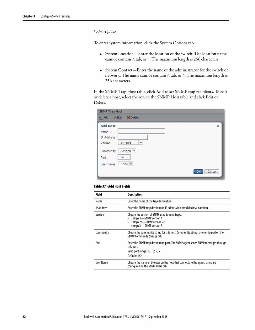
Chapter 3 Configure Switch Features
System Options
To enter system information, click the System Options tab:
• System Location—Enter the location of the switch. The location name cannot contain ?, tab, or ^. The maximum length is 256 characters.
• System Contact—Enter the name of the administrator for the switch or network. The name cannot contain ?, tab, or ^. The maximum length is 256 characters.
In the SNMP Trap Host table, click Add to set SNMP trap recipients. To edit or delete a host, select the row in the SNMP Host table and click Edit or Delete.
Table 37 - Add Host Fields
Field Description
Name Enter the name of the trap destination.
IP Address Enter the SNMP trap destination IP address in dotted decimal notation.
Version Choose the version of SNMP used to send traps:• snmpV1—SNMP version 1• snmpV2c—SNMP version 2c• snmpV3—SNMP version 3
Community Choose the community string for this host. Community strings are configured on the SNMP Community Strings tab.
Port Enter the SNMP trap destination port. The SNMP agent sends SNMP messages through this port. Valid port range: 1…65535Default: 162
User Name Choose the name of the user on the host that connects to the agent. Users are configured on the SNMP Users tab.
82 Rockwell Automation Publication 1783-UM009C-EN-P - September 2018

Configure Switch Features Chapter 3
Community Strings
Community strings are passwords to the MIB of the device. When you create a community, Device Manager automatically adds the community to default group default_ro_group or default_rw_group, based on the access you configure for the community (read-only or read-write). Two entries are added to the table on the Groups tab, one for version v1 and one for version v2c.
A read-only community string enables the switch to validate Get (read-only) requests from a network management station. If you set the SNMP read community, users can access MIB objects, but cannot change them.
A read-write community string enables the switch to validate Set (read-write) requests from a network management station.
If you delete a community, Device Manager automatically removes the community from the group.
To add, edit, or delete community strings, click the Community Strings tab.
Table 38 - Add Community Fields
Field Description
Community Name (Editable only when adding a string).Enter a name for the community string.Valid length: 1…255 charactersValid characters: ASCII characters from 33 …126
RO/RW Choose the type of access to the agent to permit the community string:• ro—Read-only: Authorized managers can retrieve MIB objects.• rw—Read-write: Authorized managers can retrieve and edit MIB objects.
Rockwell Automation Publication 1783-UM009C-EN-P - September 2018 83

Chapter 3 Configure Switch Features
Traps
Traps are messages that alert the SNMP manager to a condition on the network, such as improper user authentication, restarts, link status (up or down), or other significant events.
To enable and disable traps, click the Traps tab:• To enable a trap, check the corresponding checkbox and click Submit.• To disable a trap, clear the corresponding checkbox and click Submit. To
clear all checkboxes at once, click Clear All.
Table 39 - Traps Tab Checkboxes
Trap Description
coldStart The trap is generated when the device is reloaded.
warmStart The trap is generated when the SNMP server is manually started.
linkUp The trap is generated when the port changes from the Down state to the Up state.
linkDown The trap is generated when the port changes from the Up state to the Down state.
authenticationFailure The trap is generated if any network management server polls the device using SNMP with the wrong community string.
newRoot The trap is generated when STP is enabled, the topology changes, and the protocol selects a new root.
psecTrapInterfaces The trap is generated when a port security violation occurs and the violation mode is shut down. The trap message includes information about the violation, such as the interface, violation count, and error disable status. For more information, see page 74.
topologyChange The trap is generated by a bridge when any of the bridge configured ports transitions from the Learning state to the Forwarding state or from the Forwarding state to the Blocking state.
entConfigChange The trap is generated to signal a change to the last change time stamp. This trap is generated when the value of entLastChangeTime changes.
lldpRemTablesChange The trap is generated when Link Layer Discovery Protocol (LLDP) is enabled and connected to another device with LLDP. When LLDP at the remote device changes, this event is transmitted through LLDP and triggers this trap.
84 Rockwell Automation Publication 1783-UM009C-EN-P - September 2018

Configure Switch Features Chapter 3
View
To display Management Information Base (MIB) views that control the Object Identifier (OID) range that SNMPv3 users can access, click the View tab. View information is read-only, and the only available view is default_view, which is included in the default configuration in the switch software image. All groups are associated with default_view.
Users
To add, edit, or delete SNMP users, click the Users tab.
• To add a user, click Add. Complete the fields that are described as follows and click OK.
• To edit a user, click the radio button next to the user. Edit the fields that are described as follows and click OK.
• To delete a user, click the radio button next to the user and click Delete.
Table 40 - View Tab Fields
Field Description
View Name A string that identifies the view.
Subtree The OID that defines the root of the subtree for the named view.
View Type The type of view:• included—The subtree is included in the view.• excluded—The subtree is excluded from the view.
Rockwell Automation Publication 1783-UM009C-EN-P - September 2018 85

Chapter 3 Configure Switch Features
Group
An SNMP group is an access control policy to which you can assign users. Each SNMP group is associated with a security model and an SNMP view. A user within an SNMP group must match the security model of the SNMP group. These parameters specify what type of authentication and privacy a user within an SNMP group uses. Each SNMP group name and security model pair must be unique.
Users that you add on the Users tab automatically use the USM (SNMPv3) security model.
Table 41 - Add User Fields
Field Description
User Name (Editable only when adding a user).Enter a name to identify the user. Valid length: 1…32 charactersValid characters: ASCII characters from 33 …126
Security Level Choose a security level for the user:• snmpNoAuthNoPriv—No authentication and no privacy.• snmpAuthNoPriv—Authentication and no privacy.• snmpAuthPriv—Authentication and privacy.
Authentication Protocol (Editable when the security level is snmpAuthNoPriv or snmpAuthPriv).Choose an authentication protocol for the user:• snmpNoAuthProtocol—No authentication protocol. This protocol is
automatically assigned when the security level is snmpNoAuthNoPriv.• snmpMD5AuthProtocol—MD5 Message-Digest Algorithm authentication
protocol.• snmpSHAAuthProtocol—Secure Hash Algorithm authentication protocol.
Authentication Password Enter an authentication password phrase. Valid length for MD5 authentication protocol: 8…32 charactersValid length for SHA authentication protocol: 8…40 charactersValid characters: ASCII characters from 33…126Enter a password within these guidelines:• Must be at least eight alphanumeric characters long • Must contain an uppercase character, a lowercase character, a special character
such as @$!%*+=_?&, and a number• Is case sensitive• Cannot contain a tab, nor space at the beginning or end
Privacy Protocol (Editable when the security level is snmpAuthPriv).Choose a privacy protocol for the user:• snmpNoPrivProtocol—No privacy protocol. This protocol is automatically
assigned when the security level is snmpNoAuthNoPriv or snmpAuthNoPriv.• snmpDESPrivProtocol—Data Encryption Standard privacy protocol.• snmpAESPrivProtocol—Advanced Encryption Standard privacy protocol.
Privacy Password Enter a privacy password phrase. Valid length: 8…32 charactersValid characters: ASCII characters from 33…126 Enter a password within these guidelines:• Must be at least eight alphanumeric characters long • Must contain an uppercase character, a lowercase character, a special character
such as @$!%*+=_?&, and a number• Is case sensitive• Cannot contain a tab, nor space at the beginning or end
86 Rockwell Automation Publication 1783-UM009C-EN-P - September 2018
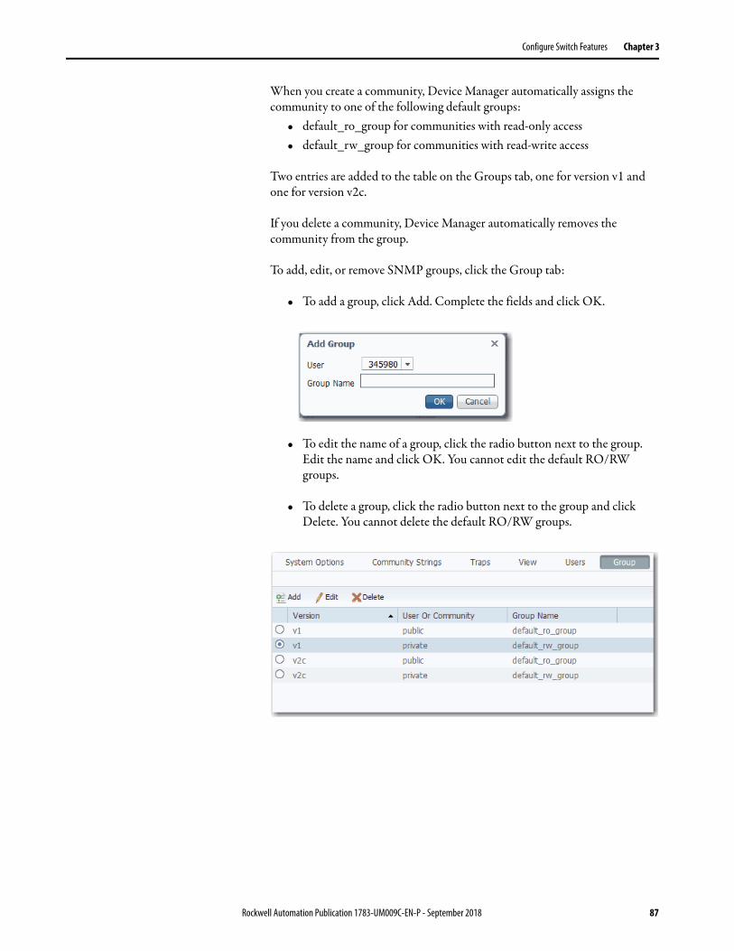
Configure Switch Features Chapter 3
When you create a community, Device Manager automatically assigns the community to one of the following default groups:
• default_ro_group for communities with read-only access• default_rw_group for communities with read-write access
Two entries are added to the table on the Groups tab, one for version v1 and one for version v2c.
If you delete a community, Device Manager automatically removes the community from the group.
To add, edit, or remove SNMP groups, click the Group tab:
• To add a group, click Add. Complete the fields and click OK.
• To edit the name of a group, click the radio button next to the group. Edit the name and click OK. You cannot edit the default RO/RW groups.
• To delete a group, click the radio button next to the group and click Delete. You cannot delete the default RO/RW groups.
Rockwell Automation Publication 1783-UM009C-EN-P - September 2018 87

Chapter 3 Configure Switch Features
Table 42 - Group Tab Fields
Field Description
Version (Not editable). Displays the security model for the group:• v1—SNMPv1• v2c—SNMPv2c• usm—SNMPv3 User-based Security Model (USM)
User or Community (Editable only when adding a group).Enter the name of the user or community to assign to the group.You must add users on the Users tab before you can assign them to a group.Communities are automatically assigned to the default_ro_group or default_rw_group when you create the community on the Community Strings tab.
Group Name Enter a name to identify the group. Valid length: 1…32 charactersValid characters: ASCII characters from 33…126
88 Rockwell Automation Publication 1783-UM009C-EN-P - September 2018

Configure Switch Features Chapter 3
Smartports Smartports are recommended configurations for switch ports. These configurations, referred to as Smartport roles, optimize the switch connections and provide security, transmission quality, and reliability for traffic from the switch ports. Smartport roles also help prevent port misconfigurations. You can apply a Smartport role to a specific port or multiple ports.
The Smartport roles that are described in Table 43 are based on the type of devices to be connected to the switch ports. For example, the Desktop for Automation port role is specifically for switch ports to be connected to desktop and laptop computers.
You can assign Smartport roles in Device Manager or the Logic Designer application.
IMPORTANT • Use Smartports immediately after the initial setup of the switch to configure the switch ports before they connect to devices.
• Always verify that the correct Smartport Role is applied before you connect a device to the port or reconnect a device that was moved.
• When you apply a Smartport role, some existing settings on the port are removed.
• We recommend that you do not change the port settings after enabling a Smartport role. Any such changes can alter the effectiveness of the Smartport role.
Table 43 - Smartport Roles
Role Description
Automation Device Apply this role to ports to be connected to EtherNet/IP (Ethernet Industrial Protocol) devices. It can be used for industrial automation devices, such as logic controllers and I/O:• Port is set to Access mode.• Port security supports only one MAC address.
Multiport Automation Device Apply this role to ports connected to multiport EtherNet/IP devices. Devices include multiport EtherNet/IP devices that are arranged in a linear or daisy chain topology, the 1783-ETAP module (for connection to only the device port), unmanaged switches, such as the Stratix 2000, and managed switches with Remote Spanning Tree Protocol (RSTP) disabled:• Port is set to Access mode.• No port security.
Desktop for Automation Apply this role to ports to be connected to desktop devices, such as desktop computers, workstations, notebook computers, and other client-based hosts:• Port is set to Access mode.• Portfast enabled.• Port security supports only one MAC address. Do not apply to ports to be connected to switches, routers, or access points.
Virtual Desktop for Automation Apply this role to ports connected to computer running virtualization software. Virtual Desktop for Automation can be used with devices running up to two MAC addresses:• Port is set to Access mode.• Portfast is enabled.• Port security supports two MAC addresses.IMPORTANT: Do not apply the Virtual Desktop for Automation role to ports that are connected to switches, routers, or access points.
Switch for Automation Apply this role to ports to be connected to other switches with Spanning Tree enabled.Port is set to Trunk mode.
Wireless-automation-access (Available in Device Manager only). Apply this role to ports to be connected to wireless access points that use a single VLAN.
Wireless-automation-trunk (Available in Device Manager only). Apply this role to ports to be connected to wireless access points that use multiple VLANs.
Rockwell Automation Publication 1783-UM009C-EN-P - September 2018 89

Chapter 3 Configure Switch Features
Avoid Smartport Mismatches
A Smartport mismatch occurs when an attached device does not match the Smartport role that is applied to the switch port. Mismatches can have adverse effects on devices and your network.
Mismatches can result in the following conditions:• Affect the behavior of the attached device • Lower network performance, such as the level of QoS on CIP, wireless,
and switch traffic • Reduce restrictions on guest access to the network • Reduce protection from denial-of-service (DoS) attacks on the network• Disable or shut down the port
Assign Smartport Roles and VLANs in Device Manager
To assign Smartport roles and VLANs, follow these steps.
1. From the Configure menu, under Network, choose Smartports.
2. Check the checkbox next to the port to which to assign a Smartport role and click Edit.
3. From the Role pull-down menu, choose the Smartport role to assign to the port, or choose None to remove the assigned Smartport role.
For a description of Smartport roles, see Table 43 on page 89.
4. From the Access VLAN or Native VLAN pull-down menu, choose a VLAN to assign to the port.
5. Click Submit.
90 Rockwell Automation Publication 1783-UM009C-EN-P - September 2018

Configure Switch Features Chapter 3
Assign Smartport Roles and VLANs in the Logix Designer Application
To assign Smartport roles and VLANs, follow these steps.
1. In the navigation pane, click Smartports and VLANs.
2. Complete the fields that are described in Table 44.
3. Click Set.
Table 44 - Smartport and VLAN Assignment Fields
Field Description
Port Displays the port type (Fa for Fast Ethernet) and number.
Smartport Choose the Smartport role to apply to the connected port. For descriptions of each role, see Table 43 on page 89.
VLAN Type and ID
Native Choose the native VLAN ID for ports set to Switch for Automation. A native VLAN is for ports that can belong to multiple VLAN.
Access Choose the access VLAN ID for ports set to Automation Device, Desktop for Automation, Phone for Automation, or Automation Device. An access VLAN is for ports that can belong to only one VLAN.
Voice Not available in the current release.
Rockwell Automation Publication 1783-UM009C-EN-P - September 2018 91

Chapter 3 Configure Switch Features
Spanning Tree Protocol (STP) STP is a Layer 2 link management protocol that provides path redundancy while helping to prevent loops in the network. For a Layer 2 Ethernet network to function properly, only one active path can exist between any two stations. Multiple active paths among end stations cause loops in the network. If a loop exists in the network, end stations can receive duplicate messages. Switches can also learn end-station MAC addresses on multiple Layer 2 interfaces. These conditions result in an unstable network. Spanning-tree operation is transparent to end stations, which cannot detect whether they are connected to a single LAN segment or a switched LAN of multiple segments.
The STP uses a spanning-tree algorithm to select one switch of a redundantly connected network as the root of the spanning tree. The algorithm calculates the best loop-free path through a switched Layer 2 network by assigning a role to each port based on the role of the port in the active topology:
• Root—A forwarding port that is elected for the spanning-tree topology.
• Designated—A forwarding port that is elected for every switched LAN segment.
• Alternate—A blocked port providing an alternate path to the root bridge in the spanning tree.
• Backup—A blocked port in a loopback configuration.
The switch that has the Designated role or the Backup role assigned to all of its ports is the root switch. The switch that has the Designated role assigned to at least one of its ports is called the designated switch.
Spanning tree forces redundant data paths into a standby (blocked) state. If a network segment in the spanning tree fails and a redundant path exists, the spanning-tree algorithm recalculates the spanning-tree topology and activates the standby path. Switches send and receive spanning-tree frames, called bridge protocol data units (BPDUs), at regular intervals. The switches do not forward these frames but use them to construct a loop-free path. BPDUs contain information about the sending switch and its ports, including switch and MAC addresses, switch priority, port priority, and path cost. Spanning tree uses this information to elect the root switch and root port for the switched network and the root port and designated port for each switched segment.
For more information about STP, see the IEEE 802.1D MAC Bridges Standard.
92 Rockwell Automation Publication 1783-UM009C-EN-P - September 2018

Configure Switch Features Chapter 3
Spanning Tree Modes
The switch supports three Spanning Tree modes, as described in Table 45.
PortFast Features
PortFast features are typically enabled only on access ports. Access ports connect to devices such as personal computers, access points, and servers that are not expected to send bridge protocol data units (BPDUs). These features are typically not enabled on ports that connect to switches because spanning tree loops can occur.
Switches exchange special frames that are called BPDUs to communicate network information, to track changes, and to create the STP topology. Because transmitted BPDUs reveal network information and received BPDUs can influence your STP topology, consider enabling BPDU Filtering and BPDU Guard on your access ports. These features help prevent a rogue device from interfering with your STP topology. However, we recommend that you use these features with caution:
• BPDU Filtering—This PortFast feature blocks all sending and receipt of BPDUs through all PortFast-enabled ports. This feature effectively disables STP on these ports and loops can result. If a BPDU is received, PortFast is disabled on the port and the global STP settings apply.
• BPDU Guard—This PortFast feature shuts down a port if it receives a BPDU.
If you enable both of these features, BPDU Guard has no effect because BPDU Filtering restricts the port from receiving any BPDUs.
Spanning tree requires an interface to progress through the listening and learning states, to exchange information and establish a loop-free path before it can forward frames. On ports that connect to devices such as workstations and servers, you can allow an immediate connection. PortFast immediately transitions the port into STP forwarding mode upon linkup.
Table 45 - Spanning Tree Modes
Mode Description
STP (Spanning Tree Protocol) Creates a spanning tree within a network of connected, Layer 2 switches and disables links that are not part of the spanning tree. Creates a single active path between any two network nodes.
MSTP (Multiple Spanning Tree Protocol) Multiple VLANs are mapped to the same spanning-tree instance, reducing the number of spanning-tree instances that are needed to support many VLANs. MSTP is the default mode.
RSTP (Rapid Spanning Tree Protocol) Provides rapid convergence of the spanning tree through explicit handshaking that minimizes the 802.1D forwarding delay and quickly transitions root ports and designated ports to the forwarding state.
Rockwell Automation Publication 1783-UM009C-EN-P - September 2018 93

Chapter 3 Configure Switch Features
Configure STP in Device Manager
To configure STP, follow these steps.
1. From the Configure menu, under Spanning Tree, choose STP Settings.
2. On the Global tab, configure STP system settings for all STP bridge instances in the switch and click Submit.
IMPORTANT To change the Spanning Tree mode or the bridge priority affects connectivity to the switch. You can only change one of these settings at a time.
94 Rockwell Automation Publication 1783-UM009C-EN-P - September 2018
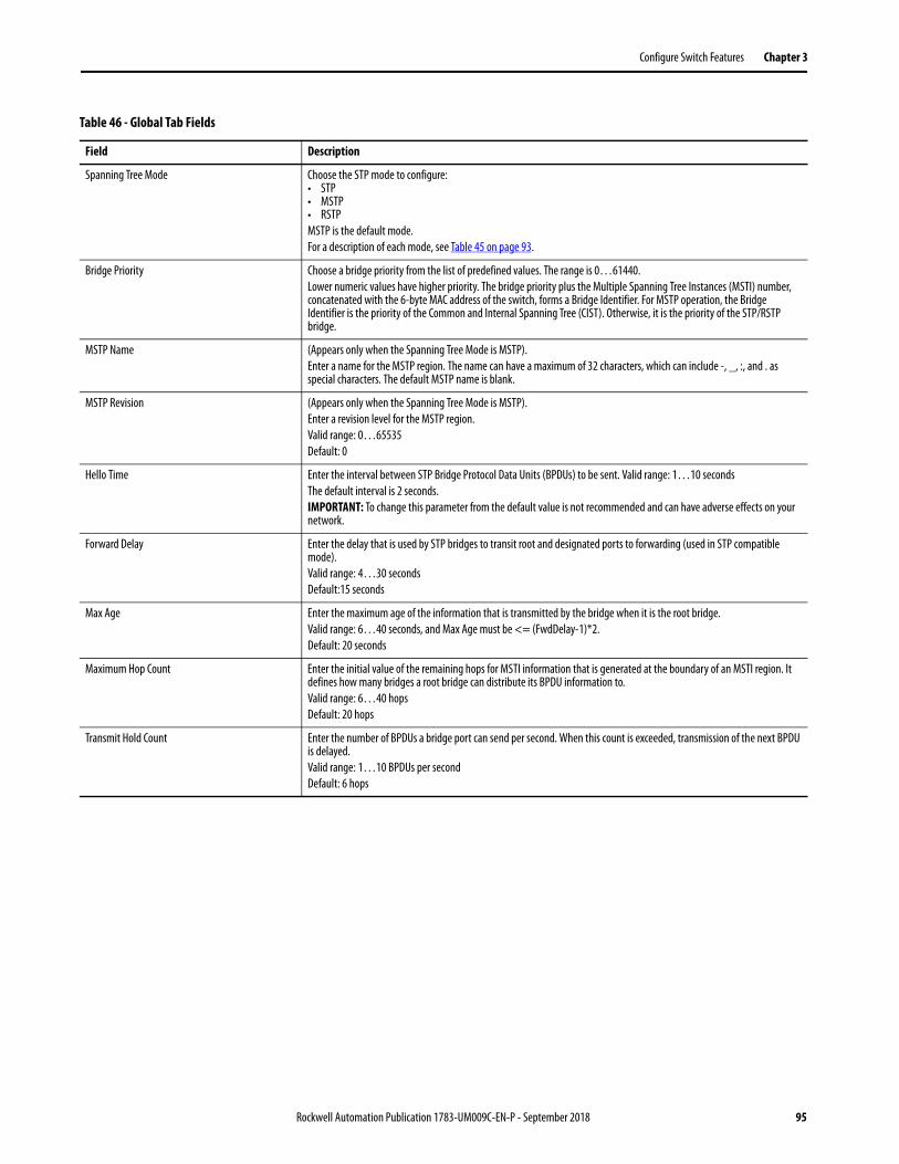
Configure Switch Features Chapter 3
Table 46 - Global Tab Fields
Field Description
Spanning Tree Mode Choose the STP mode to configure:• STP• MSTP• RSTPMSTP is the default mode.For a description of each mode, see Table 45 on page 93.
Bridge Priority Choose a bridge priority from the list of predefined values. The range is 0…61440.Lower numeric values have higher priority. The bridge priority plus the Multiple Spanning Tree Instances (MSTI) number, concatenated with the 6-byte MAC address of the switch, forms a Bridge Identifier. For MSTP operation, the Bridge Identifier is the priority of the Common and Internal Spanning Tree (CIST). Otherwise, it is the priority of the STP/RSTP bridge.
MSTP Name (Appears only when the Spanning Tree Mode is MSTP).Enter a name for the MSTP region. The name can have a maximum of 32 characters, which can include -, _, :, and . as special characters. The default MSTP name is blank.
MSTP Revision (Appears only when the Spanning Tree Mode is MSTP).Enter a revision level for the MSTP region. Valid range: 0…65535Default: 0
Hello Time Enter the interval between STP Bridge Protocol Data Units (BPDUs) to be sent. Valid range: 1…10 secondsThe default interval is 2 seconds.IMPORTANT: To change this parameter from the default value is not recommended and can have adverse effects on your network.
Forward Delay Enter the delay that is used by STP bridges to transit root and designated ports to forwarding (used in STP compatible mode). Valid range: 4…30 secondsDefault:15 seconds
Max Age Enter the maximum age of the information that is transmitted by the bridge when it is the root bridge. Valid range: 6…40 seconds, and Max Age must be <= (FwdDelay-1)*2. Default: 20 seconds
Maximum Hop Count Enter the initial value of the remaining hops for MSTI information that is generated at the boundary of an MSTI region. It defines how many bridges a root bridge can distribute its BPDU information to. Valid range: 6…40 hopsDefault: 20 hops
Transmit Hold Count Enter the number of BPDUs a bridge port can send per second. When this count is exceeded, transmission of the next BPDU is delayed. Valid range: 1…10 BPDUs per secondDefault: 6 hops
Rockwell Automation Publication 1783-UM009C-EN-P - September 2018 95

Chapter 3 Configure Switch Features
3. To add a Multiple Spanning Tree (MST) instance and map VLANs to the instance, click Add, enter the instance and VLAN numbers and click OK.
You can add a maximum of seven MST instances. The default instance is 0.
All unmapped VLANs are mapped to instance 0. You cannot delete instance 0.
4. On the Port Fast tab, specify the features to enable on all PortFast-enabled ports and click Submit:• To enable a feature, check Enable.• To disable a feature, clear the Enable checkbox.
By default, all features are enabled.
Table 47 - Port Fast Fields
Field Description
BPDU Filtering Avoids transmitting BPDUs on PortFast-enabled ports that are connected to an end system. When you enable PortFast on the device, spanning tree places ports in the forwarding state immediately, instead of going through the listening, learning, and forwarding states.
BPDU Guard Helps prevent loops by moving a non-trunking port into an errdisable state when a BPDU is received on that port. When you enable BPDU guard on the switch, Spanning Tree shuts down PortFast-configured interfaces that receive BPDUs instead of putting them into the spanning tree blocking state. In a valid configuration, PortFast-configured interfaces do not receive BPDUs. If a PortFast-configured interface receives a BPDU, an invalid configuration exists. BPDU guard provides a secure response to invalid configurations because the administrator must manually put the interface back in service.
Port Error Recovery Controls whether a port in the error-disabled state is automatically enabled after a certain time. If recovery is not enabled, ports must be disabled and re-enabled for normal STP operation. The condition is also cleared by a system restart.
Port Error Recovery Timeout Enter the time to pass before a port in the error-disabled state can be enabled. Valid range: 30…6400 seconds (24 hours)Default: 30
96 Rockwell Automation Publication 1783-UM009C-EN-P - September 2018

Configure Switch Features Chapter 3
5. To configure how STP is implemented on individual ports, click a row in the Port-Interface Port Fast table, edit the settings, and click Save.
Table 48 - Port-Interface Port Fast Table Fields
Field Description
Port Name Displays the port type (Fa for Fast Ethernet) and number.
Port Type Displays whether the port is an access port, trunk port, or hybrid port.
STP Enabled Check STP Enabled to enable Spanning Tree Protocol on the port. By default, this setting is enabled.
Admin Edge Check Admin Edge to enable the PortFast feature on the port. PortFast enables the port to bypass the listening and learning states and move immediately to forwarding.By default, this setting is disabled.
Auto Edge Check Auto Edge to enable the port to transition to and from an edge port state automatically:• When the port receives a BPDU, the port automatically transitions from an edge port state into an STP port.• When the port stops receiving a BPDU, the port automatically becomes an edge port and transitions through the discarding and learning
states before resuming forwarding.By default, this setting is enabled.
PathCost Mode Choose a mode to determine how the path cost incurred by the port:• Auto—Sets the path cost as appropriate by the physical link speed by using the 802.1D recommended values.• Specific—Allows you to enter a user-defined value. The default mode is Auto.
Path Cost (Editable when PathCost Mode is Specific).Enter the path cost to use when establishing the active topology of the network. Lower path cost ports are chosen as forwarding ports in favor of higher path cost ports. Valid range: 1…200000000
Priority Choose a priority to assign to the port. Priority can be used to control ports having identical Path Cost. The lower the priority number, the higher the priority.Valid range: 0…240 Default: 128
Point-to-point Choose whether the port connects to a point-to-point LAN rather than to a shared medium:• auto—The connection is automatically determined.• forceFalse—The port connects to a shared medium.• forceTrue—The port connects to a point-to-point LAN.Transition to the forwarding state is faster for point-to-point LANs than for shared media. The default method is auto.
BPDU Guard Check BPDU Guard to cause the port to disable itself upon receiving valid BPDUs. The edge status of the port does not affect this setting.By default, this setting is disabled.
Restricted Role Check Restricted Role to cause the root port not to be selected as the root port for the CIST or any MSTI, even if it has the best spanning tree priority vector. A port with this setting is selected as an alternate port after the root port has been selected. IMPORTANT: If enabled, Restricted Role can cause a lack of spanning tree connectivity. A network administrator can use this setting to help prevent bridges external to a core region of the network from influencing the spanning tree active topology. This feature is also known as Root Guard.By default, this setting is disabled.
Restricted TCN Check Restricted TCN to cause the port not to propagate received topology change notifications (TCNs) and topology changes to other ports. IMPORTANT: If enabled, Restricted TCN can cause temporary loss of connectivity after changes in the active topology of a spanning tree as a result of persistently incorrect learned station location information. A network administrator can use this setting to help prevent bridges external to a core region of the network to cause flushing of addresses in that region.By default, this setting is disabled.
Rockwell Automation Publication 1783-UM009C-EN-P - September 2018 97
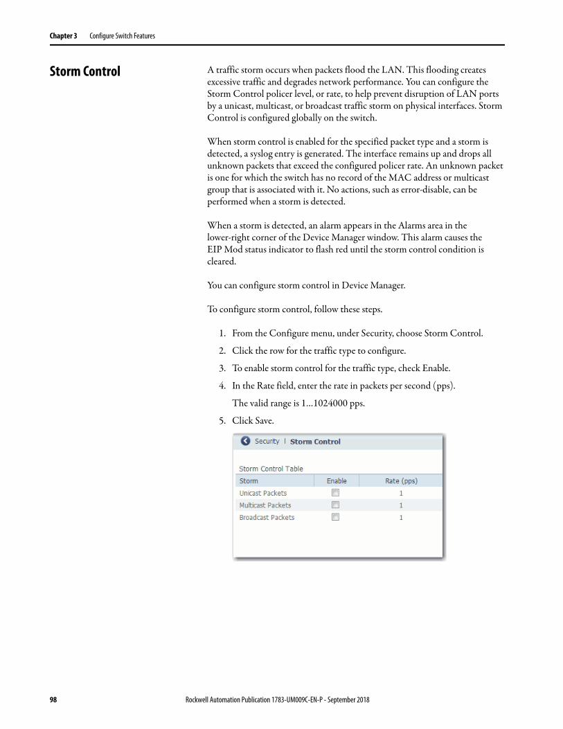
Chapter 3 Configure Switch Features
Storm Control A traffic storm occurs when packets flood the LAN. This flooding creates excessive traffic and degrades network performance. You can configure the Storm Control policer level, or rate, to help prevent disruption of LAN ports by a unicast, multicast, or broadcast traffic storm on physical interfaces. Storm Control is configured globally on the switch.
When storm control is enabled for the specified packet type and a storm is detected, a syslog entry is generated. The interface remains up and drops all unknown packets that exceed the configured policer rate. An unknown packet is one for which the switch has no record of the MAC address or multicast group that is associated with it. No actions, such as error-disable, can be performed when a storm is detected.
When a storm is detected, an alarm appears in the Alarms area in the lower-right corner of the Device Manager window. This alarm causes the EIP Mod status indicator to flash red until the storm control condition is cleared.
You can configure storm control in Device Manager.
To configure storm control, follow these steps.
1. From the Configure menu, under Security, choose Storm Control.
2. Click the row for the traffic type to configure.
3. To enable storm control for the traffic type, check Enable.
4. In the Rate field, enter the rate in packets per second (pps).
The valid range is 1…1024000 pps.
5. Click Save.
98 Rockwell Automation Publication 1783-UM009C-EN-P - September 2018
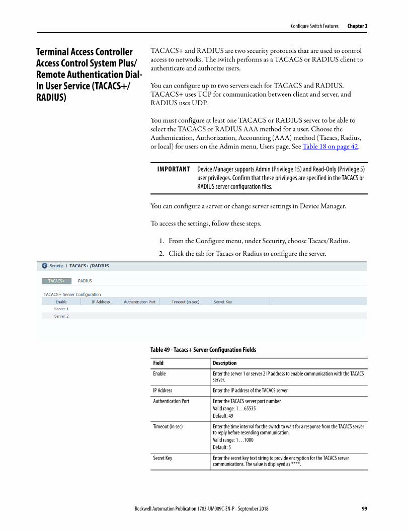
Configure Switch Features Chapter 3
Terminal Access Controller Access Control System Plus/Remote Authentication Dial-In User Service (TACACS+/RADIUS)
TACACS+ and RADIUS are two security protocols that are used to control access to networks. The switch performs as a TACACS or RADIUS client to authenticate and authorize users.
You can configure up to two servers each for TACACS and RADIUS. TACACS+ uses TCP for communication between client and server, and RADIUS uses UDP.
You must configure at least one TACACS or RADIUS server to be able to select the TACACS or RADIUS AAA method for a user. Choose the Authentication, Authorization, Accounting (AAA) method (Tacacs, Radius, or local) for users on the Admin menu, Users page. See Table 18 on page 42.
You can configure a server or change server settings in Device Manager.
To access the settings, follow these steps.
1. From the Configure menu, under Security, choose Tacacs/Radius.
2. Click the tab for Tacacs or Radius to configure the server.
IMPORTANT Device Manager supports Admin (Privilege 15) and Read-Only (Privilege 5) user privileges. Confirm that these privileges are specified in the TACACS or RADIUS server configuration files.
Table 49 - Tacacs+ Server Configuration Fields
Field Description
Enable Enter the server 1 or server 2 IP address to enable communication with the TACACS server.
IP Address Enter the IP address of the TACACS server.
Authentication Port Enter the TACACS server port number.Valid range: 1…65535Default: 49
Timeout (in sec) Enter the time interval for the switch to wait for a response from the TACACS server to reply before resending communication.Valid range: 1…1000Default: 5
Secret Key Enter the secret key text string to provide encryption for the TACACS server communications. The value is displayed as ****.
Rockwell Automation Publication 1783-UM009C-EN-P - September 2018 99

Chapter 3 Configure Switch Features
Virtual Local Area Networks (VLANs)
Stratix 2500 switches can segment your network into VLANs. A VLAN is a logical segment of the network that isolates traffic types and helps prevent collisions among data packets. The isolation of different types of traffic helps to preserve the quality of the transmission and to minimize excess traffic among the logical segments. VLANs can also reduce the amount of administrative effort that is required to examine requests to network resources.
Devices that are attached to the switch ports in the same VLAN can communicate only with each other and can share data. Devices that are attached to switch ports in different VLANs cannot communicate with each other through the switch, unless the switch is configured for routing. A Layer 3 switch or router must be configured to enable routing across multiple VLANs and additional security policies must be set. If your network is using a DHCP server, make sure that the server is accessible to the devices in all VLANs.
We recommend that you first determine your VLAN needs before creating VLANs. For more information about VLANs, refer to these publications:
• Converged Plantwide Ethernet (CPwE) Design and Implementation Guide, publication ENET-TD001
• Ethernet Design Considerations, publication ENET-RM002
Table 50 - Radius Server Configuration Fields
Field Description
Enable Enter the server 1 or server 2 IP address to enable communication with the RADIUS server.
IP Address Enter the IP address of the RADIUS server.
Authentication Port Enter the RADIUS UDP destination port for authentication requests.Default: 1812
Accounting Port Enter the RADIUS UDP destination port for accounting requests.Default: 1813
Timeout (in sec) Enter the time interval for the switch to wait for a response from the RADIUS server to reply before resending communication.Valid range: 1…1000Default: 5
Secret Key Enter the secret key text string to provide encryption for the RADIUS server communications. The value is displayed as ****.
100 Rockwell Automation Publication 1783-UM009C-EN-P - September 2018
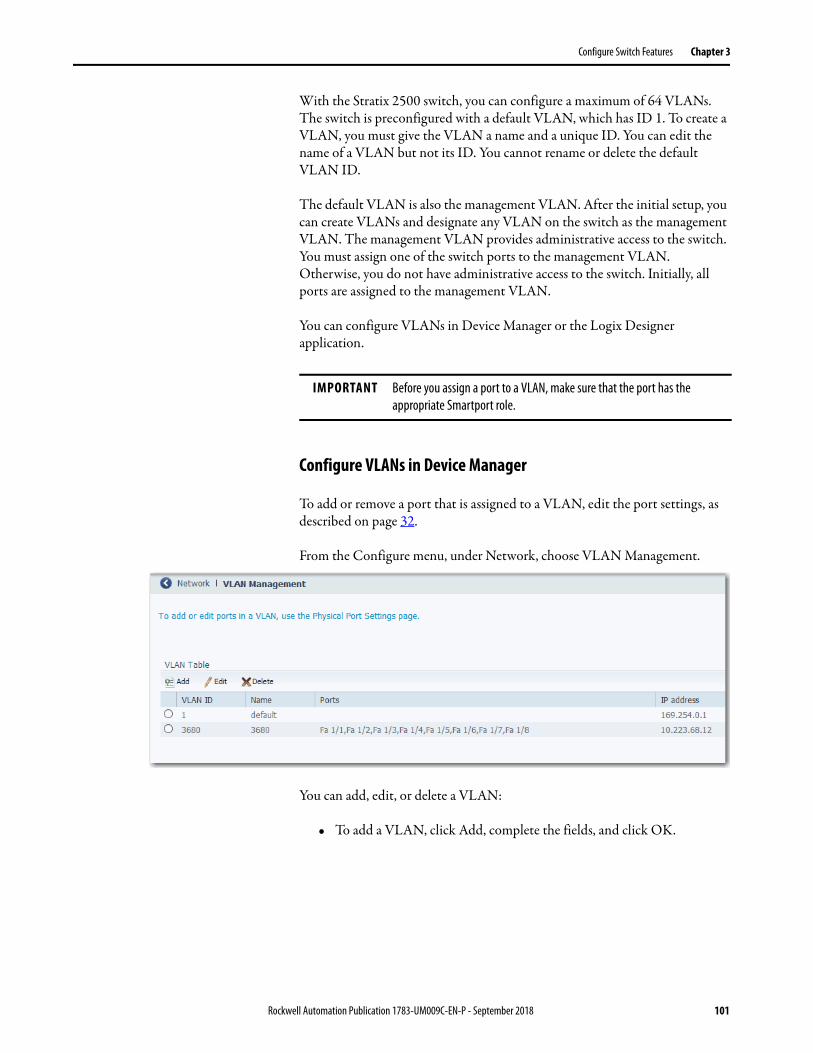
Configure Switch Features Chapter 3
With the Stratix 2500 switch, you can configure a maximum of 64 VLANs. The switch is preconfigured with a default VLAN, which has ID 1. To create a VLAN, you must give the VLAN a name and a unique ID. You can edit the name of a VLAN but not its ID. You cannot rename or delete the default VLAN ID.
The default VLAN is also the management VLAN. After the initial setup, you can create VLANs and designate any VLAN on the switch as the management VLAN. The management VLAN provides administrative access to the switch. You must assign one of the switch ports to the management VLAN. Otherwise, you do not have administrative access to the switch. Initially, all ports are assigned to the management VLAN.
You can configure VLANs in Device Manager or the Logix Designer application.
Configure VLANs in Device Manager
To add or remove a port that is assigned to a VLAN, edit the port settings, as described on page 32.
From the Configure menu, under Network, choose VLAN Management.
You can add, edit, or delete a VLAN:
• To add a VLAN, click Add, complete the fields, and click OK.
IMPORTANT Before you assign a port to a VLAN, make sure that the port has the appropriate Smartport role.
Rockwell Automation Publication 1783-UM009C-EN-P - September 2018 101

Chapter 3 Configure Switch Features
• To edit a VLAN, click the radio button next to the VLAN. Click Edit, edit the fields, and click OK.
You can edit the name of a VLAN, but not the VLAN ID.
• To delete a VLAN, click the radio button next to the VLAN and click Delete.
Configure VLANs in the Logix Designer Application
To assign ports to VLANs, see page 91.
Table 51 - Add VLAN Fields
Field Description
Create a single VLANVLAN ID, Name
Click this radio button to configure one VLAN, and then enter a unique ID and name to identify the VLAN.Valid range: 1…4094
IP Assignment ModeIP Address
(Editable only when Create a single VLAN is clicked).Click to specify how to assign an IP address for the VLAN:• No IP Address—Assign no IP address.• Static—Assign a static IP address.• DHCP—Allow a DHCP server to assign an IP address.If you clicked Static, then in the IP Address fields, enter the static IP address and subnet mask to assign to the VLAN.
Create a range of VLANsVLAN Range
Click this radio button to configure multiple VLANs and to enter a range of numbers to identify each VLAN.Valid range: 1…4094
102 Rockwell Automation Publication 1783-UM009C-EN-P - September 2018
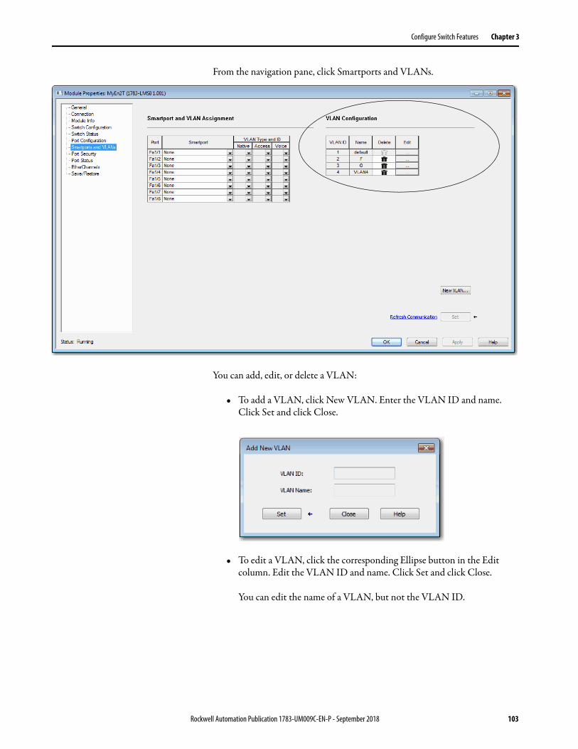
Configure Switch Features Chapter 3
From the navigation pane, click Smartports and VLANs.
You can add, edit, or delete a VLAN:
• To add a VLAN, click New VLAN. Enter the VLAN ID and name. Click Set and click Close.
• To edit a VLAN, click the corresponding Ellipse button in the Edit column. Edit the VLAN ID and name. Click Set and click Close.
You can edit the name of a VLAN, but not the VLAN ID.
Rockwell Automation Publication 1783-UM009C-EN-P - September 2018 103

Chapter 3 Configure Switch Features
• To delete a VLAN, click the corresponding Trash icon in the Delete column and click Set.
104 Rockwell Automation Publication 1783-UM009C-EN-P - September 2018
Chapter 4
Monitor the Switch
This chapter describes tools to monitor the switch in Device Manager and the Studio 5000 Logix Designer® application.
Topic Page
Dashboard 106
System Alarms 111
Port Statistics 112
Port Security Statistics 113
CIP Status 115
DHCP Clients Status 117
System Log Messages 117
Ping Utility 119
Switch Status 120
Module Information 122
Port Status 123
Port Diagnostics 124
Rockwell Automation Publication 1783-UM009C-EN-P - September 2018 105

Chapter 4 Monitor the Switch
Dashboard The dashboard in Device Manager lets you monitor the following: • Front panel status indicators• Switch information• Switch health• Port utilization
Figure 2 - Dashboard
Front Panel
The Front Panel area on the dashboard is a graphical display of the front panel on the physical switch. The switch components on the front panel view are color-coded by status.
To display specific information about a port and its status, hover your mouse pointer over a port image, as shown in the following graphic.
106 Rockwell Automation Publication 1783-UM009C-EN-P - September 2018

Monitor the Switch Chapter 4
Figure 3 - Port Hover Text
For descriptions of the IEP Mod, EIP Net, and Setup status indicators, see System Status Indicators on page 136.
Switch Information
The Switch Information area on the dashboard displays information about the switch.
Table 52 - Switch Information Fields
Field Description
HostName A descriptive name for this switch. The default name is Switch. You can set this parameter on the Express Setup page.
IP Address The IP address of this switch. You can configure this setting on the Express Setup page.
MAC Address The MAC address of this switch. This information cannot be changed.
Product ID The model of this switch. This information cannot be changed.
Rockwell Automation Publication 1783-UM009C-EN-P - September 2018 107

Chapter 4 Monitor the Switch
Switch Health
The Switch Health area on the dashboard displays gauges to monitor CPU utilization and temperature.
The CPU Utilization gauge shows the percentage of CPU processing power that is in use on the switch. Data is collected at each 60-second system refresh. The gauge changes as the switch experiences the network activity from devices sending data through the network. As network activity increases, so does contention between devices to send data through the network.
As you monitor utilization on the switch, note whether the percentage of usage is what you expect during that given time of network activity. If utilization is high when you expect it to be low, perhaps a problem exists. As you monitor the switch, note if the bandwidth utilization is consistently high, which can indicate congestion in the network. If the switch reaches its maximum bandwidth (above 90% utilization) and its buffers become full, it begins to discard the data packets that it receives. Some packet loss in the network is not considered unusual, and the switch is configured to help recover lost packets,
CIP Revision The CIP revision that is supported by the firmware revision that switch is running. The supported CIP revision changes with firmware updates.
CIP Serial Number The CIP serial number. This information cannot be changed.
Serial Number The serial number of this switch. This information cannot be changed.
Active Image The firmware revision that the switch is running. This information is updated when you upgrade the switch firmware.
Backup Image The firmware revision that is stored as a backup. You can change to the backup revision on the Software Update page.
Contact The person who is the administrative contact for this switch. You can set this parameter on the SNMP page.
Location The physical location of this switch. You can set this parameter on the SNMP page.
Table 52 - Switch Information Fields (continued)
Field Description
108 Rockwell Automation Publication 1783-UM009C-EN-P - September 2018

Monitor the Switch Chapter 4
such as by signaling to other devices to resend data. However, excessive packet loss can create packet errors, which can degrade overall network performance.
To reduce congestion, consider segmenting the network into subnetworks that are connected by other switches or routers. Look for other causes, such as faulty devices or connections, which can also increase bandwidth utilization on the switch.
The Temperature gauge shows the internal temperature of the switch. For information about the switch temperature range and the operating environment guidelines, see the Stratix Ethernet Device Specifications Technical Data, publication 1783-TD001.
Port Utilization
The Port Utilization area on the dashboard displays network traffic:
• By default, all traffic is displayed for all interfaces. Click the links above the graph to display all traffic, errors, received traffic, or transmitted traffic.
• You can view the data in chart or grid format. Click the buttons below the graph to choose a format:
– Chart format
– Grid format
• When displaying a chart, position your mouse pointer over a bar or a point on the chart to view the data.
Rockwell Automation Publication 1783-UM009C-EN-P - September 2018 109

Chapter 4 Monitor the Switch
As you monitor the usage on the ports, note whether the percentage is what you expect during that given time of network activity. If usage is high when you expect it to be low, a problem can exist. Bandwidth allocation can also be based on whether the connection is operating in Half-duplex or Full-duplex mode.
110 Rockwell Automation Publication 1783-UM009C-EN-P - September 2018

Monitor the Switch Chapter 4
Reasons for errors that are received on or sent from the switch ports include the following:
• Bad cable connection• Defective ports• Software problems• Driver problems
Data is collected at each 60-second system refresh.
For more details about data and errors on ports, see Port Statistics on page 112.
System Alarms In Device Manager, you can view system alarm counts in the lower-right corner of the window. To display the table of alarm events as follows, hover your mouse pointer over the Alarms area.
Device Manager refreshes data every 60 seconds. To refresh alarms data manually, click the Refresh icon in the upper-right corner of the Device Manager window.
Alarms
Refresh Icon
Rockwell Automation Publication 1783-UM009C-EN-P - September 2018 111

Chapter 4 Monitor the Switch
Only active alarms appear. Alarms are removed from the table in the next auto-refresh cycle when the following occurs:
• You acknowledge the alarm.• You disable the alarm on the Alarm Settings page.• The alarm becomes inactive.• You clear logs on the Syslog page.
To suppress an active alarm, select the alarm in the Alarms table and click Acknowledge Alarms. To acknowledge an alarm turns off the associated status indicator that is lit when the alarm is raised and removes the alarm from the Alarms table.
Port Statistics On the Port Statistics page, you can view statistics for data that passes through the switch ports.
In Device Manager, from the Monitor menu, under Statistics, choose Port Statistics.
IMPORTANT System alarms are filtered from the Syslog page, so Enable Syslog must be checked on the Alarm Settings page under the Configuration menu.
112 Rockwell Automation Publication 1783-UM009C-EN-P - September 2018
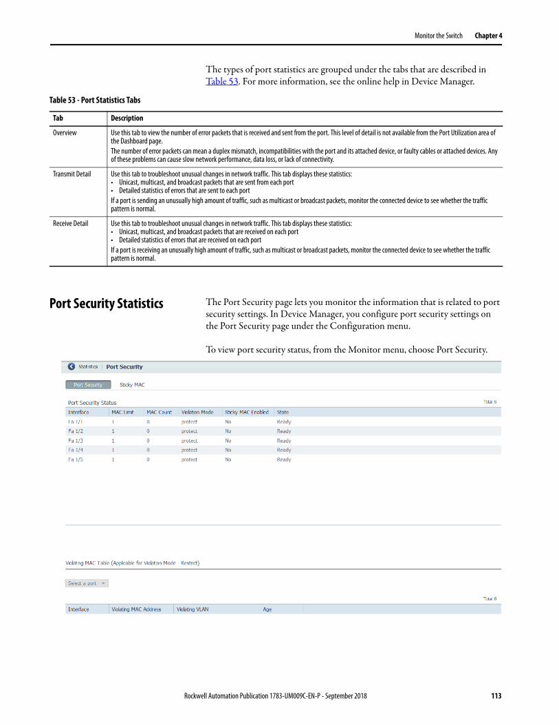
Monitor the Switch Chapter 4
The types of port statistics are grouped under the tabs that are described in Table 53. For more information, see the online help in Device Manager.
Port Security Statistics The Port Security page lets you monitor the information that is related to port security settings. In Device Manager, you configure port security settings on the Port Security page under the Configuration menu.
To view port security status, from the Monitor menu, choose Port Security.
Table 53 - Port Statistics Tabs
Tab Description
Overview Use this tab to view the number of error packets that is received and sent from the port. This level of detail is not available from the Port Utilization area of the Dashboard page.The number of error packets can mean a duplex mismatch, incompatibilities with the port and its attached device, or faulty cables or attached devices. Any of these problems can cause slow network performance, data loss, or lack of connectivity.
Transmit Detail Use this tab to troubleshoot unusual changes in network traffic. This tab displays these statistics:• Unicast, multicast, and broadcast packets that are sent from each port• Detailed statistics of errors that are sent to each portIf a port is sending an unusually high amount of traffic, such as multicast or broadcast packets, monitor the connected device to see whether the traffic pattern is normal.
Receive Detail Use this tab to troubleshoot unusual changes in network traffic. This tab displays these statistics:• Unicast, multicast, and broadcast packets that are received on each port• Detailed statistics of errors that are received on each portIf a port is receiving an unusually high amount of traffic, such as multicast or broadcast packets, monitor the connected device to see whether the traffic pattern is normal.
Rockwell Automation Publication 1783-UM009C-EN-P - September 2018 113

Chapter 4 Monitor the Switch
Below the Port Security Status tabs, you can view information about the violating MAC addresses in the Violating MAC Table. This table displays data only for interfaces that meet these conditions, as configured on the Port Security page under the Configuration menu:
• The Violation mode is set to ‘restrict.’ • The value that is defined in the Maximum MAC Count Allowed
field has been exceeded.
Use the Sticky MAC tab to monitor the information that is related to Sticky MAC settings. To display the sticky MAC addresses for a port, select the port from the Select a port pull-down menu.
Table 54 - Port Security Tab Fields
Field Description
Interface The port type (Fa for Fast Ethernet) and number.
MAC Limit The value that is defined in the Maximum MAC Count Allowed field on the Port Security page under the Configuration menu.
MAC Count Number of learned MAC addresses.
Violation Mode The action to take if the value in the maximum number of learned MAC addresses is reached. See descriptions in Table 34 on page 74.
Sticky MAC Enabled Indicates if Sticky MAC is enabled for each Interface (Yes/No).
State Displays if the number of learned MAC addresses exceeds the configured maximum:• Ready—Maximum not reached.• Limited Reached—Number of learned MAC addresses exceeds the configured maximum.
Table 55 - Violating MAC Table Fields
Field Description
Interface The port type (Fa for Fast Ethernet) and number.
Violating MAC Address The MAC address that exceeds the limit.
Violating VLAN The VLAN associated with the violating MAC address for the interface.
Age The time that remains to flush the MAC address, or the hold time, which is measured in seconds. A value of zero means that aging is disabled.
114 Rockwell Automation Publication 1783-UM009C-EN-P - September 2018

Monitor the Switch Chapter 4
CIP Status In Device Manager, you can monitor Common Industrial Protocol (CIP) status and statistics. CIP is an application layer messaging protocol that industrial automation and control devices use to communicate as part of a control system. CIP is the application layer for the EtherNet/IP network. Stratix® switches contain an EtherNet/IP server that enables the switch to be part of the industrial automation and control system for management and monitoring.
The CIP page displays information since the switch was last powered on, was restarted, or the counters were last reset. To reset the counters to zero, click Reset Counters. To troubleshoot an issue, reset the CIP counters, and see if the counters show that the issue still exists.
From the Monitor menu, under Status, choose CIP.
Table 56 - Sticky MAC Tab Fields
Field Description
Sticky MAC Address The sticky MAC addresses for the selected port.
State Displays if the number of learned MAC addresses exceeds the configured maximum:• Forwarding—The port is active and forwarding traffic.• Violating—Number of MAC addresses exceeds the maximum.
Save Sticky MACs To save the sticky MAC addresses into the startup configuration file.Sticky MAC addresses are not automatically added to the startup configuration. If you do not save an updated configuration, the addresses are lost and the interface must relearn the addresses upon device reboot. Save the addresses into the startup configuration to essentially make these addresses static.The port type (Fa for Fast Ethernet) and number.
IMPORTANT Except for Active Multicast Groups, all other categories are related to the CIP server in the switch. The categories pertain to CIP traffic directed to the switch as a CIP target device. The categories do not refer to CIP (EtherNet/IP) traffic that flows through the switch among these devices:• Various CIP controllers• HMI devices• Configuration tools• Other CIP target devices, such as drives, I/O modules, motor starters, sensors, and valves
Rockwell Automation Publication 1783-UM009C-EN-P - September 2018 115

Chapter 4 Monitor the Switch
Table 57 - CIP Fields
Field Description
Overview—Displays the state of the DIP connection to the device.
State The state of the CIP connection (Enabled or Disabled).
VLAN The VLAN ID.
CIP I/O Connection Owner The IP address of the device to and from which application-specific I/O output data is sent and received.
CIP Config Session Owner The IP address of the device controlling the CIP configuration session.
Management CPU Utilization Percentage of the management CPU that is used for management functions. Switch functions have dedicated ASICs. Management functions do not impact the ASICs.
Active Explicit Msg Connections The number of active, explicit messaging connections to the switch as a target.
Active I/O Connections The number of active I/O connections with the switch as a target.
Active Multicast Groups The number of multicast groups, including CIP multicast groups, that flow through the switch.
Connection Details—Displays request activity.
Open Requests The number of Forward Open requests received by the switch to establish a connection with the switch.
Close Requests The number of Forward Close requests received by the switch after a connection was successfully established with the switch.
Open Format Rejects The number of Forward Open requests directed to the switch that failed because the request is not in the proper format.
Close Format Rejects The number of Forward Close requests directed to the switch that failed because the request is not in the proper format.
Open Resource Rejects The number of Forward Open requests that failed to establish a new connection for reasons such as insufficient memory.
Close Other Rejects The number of Forward Close requests that failed for reasons such as incompatible electronic keying.
Open Other Rejects The number of Forward Open requests that failed for reasons such as incompatible electronic keying.
Connection Timeouts The number of CIP connections that timed out due to inactivity.
116 Rockwell Automation Publication 1783-UM009C-EN-P - September 2018

Monitor the Switch Chapter 4
DHCP Clients Status In Device Manager, the DHCP Clients Table displays information about devices that are connected to a switch with DHCP snooping enabled. The DHCP snooping feature dynamically builds and maintains entries in the DHCP Clients Table. An entry is recorded for each untrusted host with a leased IP address, if the host is associated with a VLAN that has DHCP snooping enabled. Entries are not recorded for hosts that are connected through trusted interfaces. See DHCP Snooping on page 60 for information about setting this feature.
System Log Messages In Device Manager, the system log displays events that occur on the switch and its ports. On the Syslog page, you can configure the system log server and view system log entries by severity and type.
To clear the entries on the Syslog page, click Clear Log. Clicking Clear Log does not resolve the issues.
Table 58 - DHCP Clients Table Fields
Field Description
MAC Address Displays the client hardware MAC address.
IP Address Displays the client IP address assigned from the DHCP server.
Lease(sec) Displays IP address lease time in seconds.
VLAN ID Displays the VLAN number of the client interface.
Interface Displays the interface that connects to the DHCP client host.
Clear DHCP Clients Click to reset leases for unconnected devices.
Rockwell Automation Publication 1783-UM009C-EN-P - September 2018 117

Chapter 4 Monitor the Switch
Configure the System Log Server
To configure the system log server, follow these steps.
1. From the Monitor menu, under Troubleshoot, choose Syslog.
2. Check Enable Server.
3. In the IP Address field, type the IP address of the server where the switch sends the logs.
4. From the Message Level pull-down menu, choose the level of messages to send to the system log server.
The switch sends messages to the server at the level you choose and numerically lower levels:• informational—Sends messages with severity code of 6 or less. This
level indicates that the message is for information only.• notifications—Sends messages with severity code of 5 or less. This
level indicates that the switch is operating normally but has a significant condition.
• warnings—Sends messages with severity code of 4 or less. This level indicates that the switch has a warning condition.
• errors—Sends messages with severity code of 3 or less. This level indicates that the switch has an error condition.
5. Click Submit.
118 Rockwell Automation Publication 1783-UM009C-EN-P - September 2018

Monitor the Switch Chapter 4
View System Log Entries
To view system log entries, follow these steps.
1. From the Monitor menu, under Troubleshoot, choose Syslog.
2. From the Severity Filter pull-down menu, choose the severity of the entries to view:• all—Displays all severities.• informational—Displays informational messages.• notifications—Displays significant conditions while the switch is
operating normally.• warnings—Displays warning conditions.• errors—Displays error conditions.
3. From the Type Filter pull-down menu, choose the type of message of view:• NONE—Displays all types.• SYS-BOOTING—Displays system boot events.• SUDI verification passed—Displays Secure Unique Device Identifier
(SUDI) events.• LINK-UPDOWN—Displays interface state change events.
Ping Utility In Device Manager, use the Ping Utility to troubleshoot connectivity from the switch to another device.
Enter the IP address or host name and click Ping to initiate a request for information. The response is displayed in the Ping Statistics field.
Rockwell Automation Publication 1783-UM009C-EN-P - September 2018 119

Chapter 4 Monitor the Switch
Switch Status The Switch Status view in the Studio 5000 Logix Designer application lets you view status parameters for the switch.
In the navigation pane, click Switch Status.
Table 59 - Ping Utility Fields
Field Description
IP Address/DNS Name Enter the IP address or host name of the ping target.
Repeat Enter the number of times to reissue the ping request. Range: 1…10Default: 5
Packet Size Enter the length (in bytes) of the ping packet. Range: 2…1452 Default: 100
Clear Click to remove all current information from the Ping Statistics field.
120 Rockwell Automation Publication 1783-UM009C-EN-P - September 2018

Monitor the Switch Chapter 4
Table 60 - Switch Status Fields
Field Description
Alarms & Faults
Active Alarms Displays one of these values:• None• Port alarm• Dual Mode Power Supply alarm• Primary Temperature alarm
Major Alarm Relay Displays one of these values:• Open • Closed
Active Faults Displays one of these values:• None• Port fault• Hardware faultIf the port and hardware faults are active, the Hardware fault status appears.
Health
Switch Uptime Displays the days, hours, and minutes that the switch has been functioning since the last restart.
Switch Temperature Displays the current internal temperature (in degree Celsius) of the switch.
Bandwidth Utilization Displays the total percentage of the switch bandwidth being used.
Number of Active Multicast Groups Displays the number of active multicast groups.
Image
IOS Release Displays the current version of the switch operating system.
License File Displays whether the license file is valid.
Power
Power Present on Terminal A Displays a yes or no value to indicate whether power is present on the power terminal.
Rockwell Automation Publication 1783-UM009C-EN-P - September 2018 121
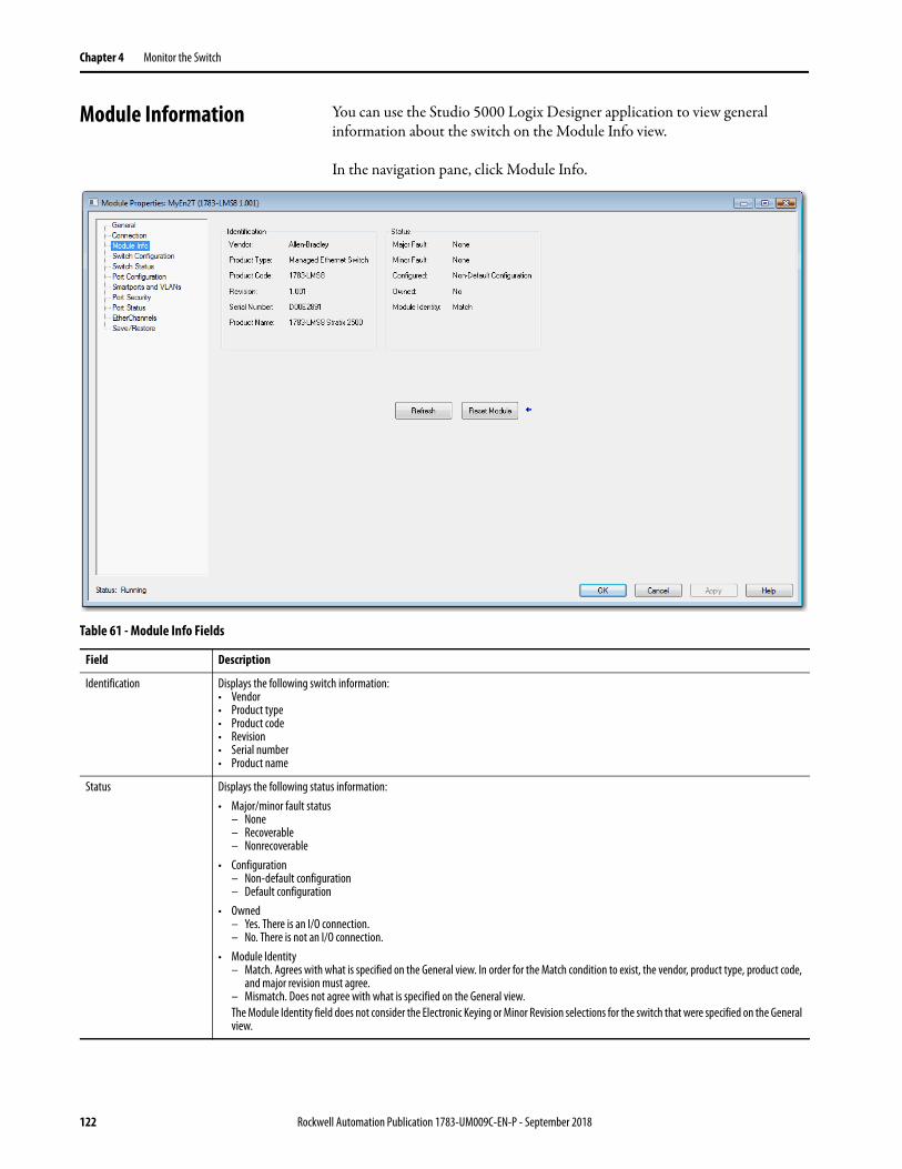
Chapter 4 Monitor the Switch
Module Information You can use the Studio 5000 Logix Designer application to view general information about the switch on the Module Info view.
In the navigation pane, click Module Info..
Table 61 - Module Info Fields
Field Description
Identification Displays the following switch information:• Vendor• Product type• Product code • Revision• Serial number• Product name
Status Displays the following status information:• Major/minor fault status
– None– Recoverable– Nonrecoverable
• Configuration– Non-default configuration– Default configuration
• Owned– Yes. There is an I/O connection.– No. There is not an I/O connection.
• Module Identity– Match. Agrees with what is specified on the General view. In order for the Match condition to exist, the vendor, product type, product code,
and major revision must agree. – Mismatch. Does not agree with what is specified on the General view.The Module Identity field does not consider the Electronic Keying or Minor Revision selections for the switch that were specified on the General view.
122 Rockwell Automation Publication 1783-UM009C-EN-P - September 2018
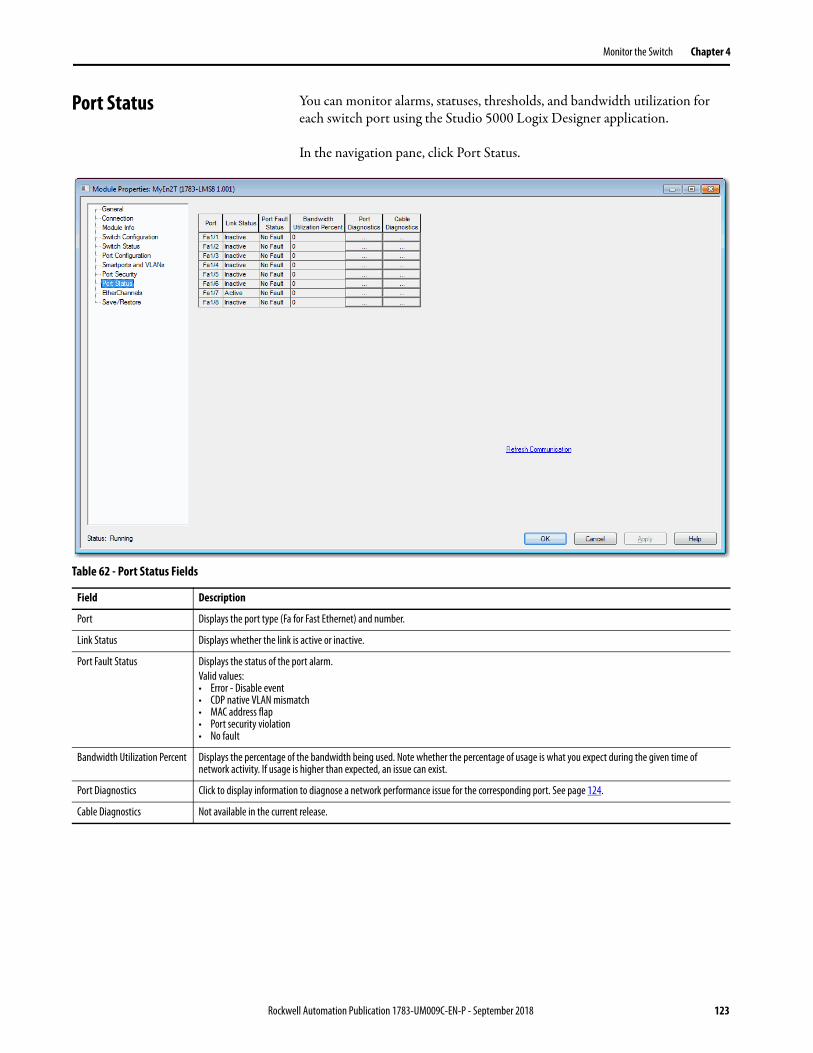
Monitor the Switch Chapter 4
Port Status You can monitor alarms, statuses, thresholds, and bandwidth utilization for each switch port using the Studio 5000 Logix Designer application.
In the navigation pane, click Port Status.
Table 62 - Port Status Fields
Field Description
Port Displays the port type (Fa for Fast Ethernet) and number.
Link Status Displays whether the link is active or inactive.
Port Fault Status Displays the status of the port alarm.Valid values:• Error - Disable event• CDP native VLAN mismatch• MAC address flap• Port security violation• No fault
Bandwidth Utilization Percent Displays the percentage of the bandwidth being used. Note whether the percentage of usage is what you expect during the given time of network activity. If usage is higher than expected, an issue can exist.
Port Diagnostics Click to display information to diagnose a network performance issue for the corresponding port. See page 124.
Cable Diagnostics Not available in the current release.
Rockwell Automation Publication 1783-UM009C-EN-P - September 2018 123

Chapter 4 Monitor the Switch
Port Diagnostics The Port Diagnostics feature in the Studio 5000 Logix Designer application lets you view the status of the link performance:
• View octet and packet counters• View collisions on the link• View errors on the link
You can also reset and clear all status counters.
In the navigation pane, click Port Status, and then click the button in the Port Diagnostics column for the corresponding port.
124 Rockwell Automation Publication 1783-UM009C-EN-P - September 2018

Monitor the Switch Chapter 4
Table 63 - Port Diagnostics Fields
Field Description
Unit Displays the switch model:• 5 Port Base• 8 Port Base
Port Displays the port type (Fa for Fast Ethernet) and number.
Interface Counters Displays the following interface counters:• Octets In—The number of octets that the port receives.• Octets Out—The number of octets that the port sends.• Ucast Packets In—The number of unicast packets that the port receives.• Ucast Packets Out—The number of unicast packets that the port sends.• NUcast packets In—The number of multicast packets that the port receives.• NUcast packets Out—The number of multicast packets that the port sends.• Discards In—The number of inbound packets that have been discarded.• Discards Out—The number of outbound packets that have been discarded.• Errors In—The number of inbound packets that contain errors.• Errors Out—The number of outbound packets that contain errors.• Unknown Protos (Protocols) In —The number of inbound packets with unknown protocols.
Media Counters Displays the following media counters:• Alignment—The number of frames received that are not an integral number of octets in length.• FCS (Frame Check Sequence)—The number of frames received that do not pass the FCS check.• SQE Test Errors —The number of times that the SQE TEST ERROR message is generated.• Deferred Transmissions—The count of transmissions that are deferred by busy network.• Late Collisions—The number of late collisions.• Excessive Collisions—The number of frames for which transmission fails due to excessive collisions.• MAC Xmit Errors—The number of frames that failed to transmit due to an internal MAC sublayer transmit error.• MAC Recv Errors—The number of frames that failed to be received due to an internal MAC sublayer receive error.• Carrier Sense—The number of times the carrier sense condition was lost or never asserted when attempting to transmit a frame.• Frame Too Long —The number of frames received that exceed the maximum permitted frame size.
Rockwell Automation Publication 1783-UM009C-EN-P - September 2018 125

Chapter 4 Monitor the Switch
Notes:
126 Rockwell Automation Publication 1783-UM009C-EN-P - September 2018

Chapter 5
Troubleshoot the Switch
This chapter helps you resolve issues that are related to Stratix® 2500 switches and perform common functions, such as reset the switch.
See also Troubleshoot EtherNet/IP Networks, publication ENET-AT003.
Topic Page
Troubleshoot the Installation 128
Troubleshoot IP Addresses 130
Troubleshoot Device Manager 131
Restart or Reset the Switch 131
Troubleshoot a Firmware Update 133
Troubleshoot with the Command-line Interface 134
Rockwell Automation Publication 1783-UM009C-EN-P - September 2018 127
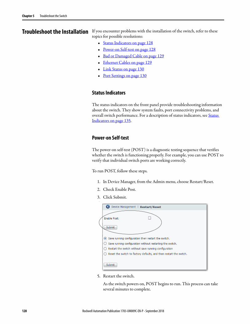
Chapter 5 Troubleshoot the Switch
Troubleshoot the Installation If you encounter problems with the installation of the switch, refer to these topics for possible resolutions:
• Status Indicators on page 128• Power-on Self-test on page 128• Bad or Damaged Cable on page 129• Ethernet Cables on page 129• Link Status on page 130• Port Settings on page 130
Status Indicators
The status indicators on the front panel provide troubleshooting information about the switch. They show system faults, port connectivity problems, and overall switch performance. For a description of status indicators, see Status Indicators on page 135.
Power-on Self-test
The power-on self-test (POST) is a diagnostic testing sequence that verifies whether the switch is functioning properly. For example, you can use POST to verify that individual switch ports are working correctly.
To run POST, follow these steps.
1. In Device Manager, from the Admin menu, choose Restart/Reset.
2. Check Enable Post.
3. Click Submit.4.
5. Restart the switch.
As the switch powers on, POST begins to run. This process can take several minutes to complete.
128 Rockwell Automation Publication 1783-UM009C-EN-P - September 2018

Troubleshoot the Switch Chapter 5
6. Check the status of the EIPMod status indicator on the front panel of the switch.
If the EIPMod status indicator remains solid red, the switch has an non-recoverable fault.
Bad or Damaged Cable
Always make sure that the cable does not have marginal damage or failure. Even if a cable can connect at the physical layer, subtle damage to the wiring or connectors can corrupt packets.
This situation is likely when the port has many packet errors or the port constantly loses and regains the link. To troubleshoot, try the following:
• Swap the copper cable with a known, undamaged cable.• Look for broken, bent, or missing pins on cable connectors.• Rule out any bad patch panel connections or media convertors between
the source and destination. If possible, bypass the patch panel, or eliminate faulty media convertors (fiber-optic-to-copper).
• Try the cable in another port or interface to determine if the problem follows the cable.
Ethernet Cables
Make sure that you have the correct cable type for the connection:• Use Category 3 copper cable for 10-Mb/s UTP connections. • Use Category 5, 5e, or 6 UTP or STP cable for 10/100-Mbps
connections.
IMPORTANT POST failures are fatal to the switch. Contact your Rockwell Automation technical support representative if your switch does not pass POST.
Rockwell Automation Publication 1783-UM009C-EN-P - September 2018 129

Chapter 5 Troubleshoot the Switch
Link Status
Verify that both sides of a network link are connected. A broken wire or disabled port can cause one side to show a connection, but not the other side. A port status indicator does not necessarily indicate that the cable is fully functional. The cable can encounter physical stress that causes it to function at a marginal level. If the port status indicator for the port is not lit, do the following:
• Connect the cable from the switch to a known good device.• Make sure that both ends of the cable are connected to the correct ports.• Verify that both devices have power.• Verify that you are using the correct cable type.• Rule out loose connections. Sometimes a cable appears to be seated, but
is not. Disconnect the cable, and then reconnect it.
Port Settings
A cause of connectivity failure can be a disabled port. Use the Port Settings page in Device Manager to verify the status of the connection. If needed, enable the interface to restore the connection.
Troubleshoot IP Addresses The following table includes basic troubleshooting for issues that are related to the switch IP address.
Issue Resolution
The switch does not receive an IP address from the DHCP server
If the switch does not receive an IP address from an upstream device operating as a DHCP server, make sure that the device is operating as a DHCP server. Repeat Express Setup.
The switch has the wrong IP address If the switch is installed in your network, but you cannot access the switch because it has the wrong IP address, assign a new switch IP address and update the switch IP address on the Express Setup page.
130 Rockwell Automation Publication 1783-UM009C-EN-P - September 2018

Troubleshoot the Switch Chapter 5
Troubleshoot Device Manager
The following table includes basic troubleshooting for Device Manager issues. If the issue persists, follow the procedure in Restart or Reset the Switch.
Restart or Reset the Switch If you cannot solve an issue by reconfiguring a feature, you can restart or reset the switch to solve the issue. If the issue exists after you reset the switch to its default settings, it is unlikely that the switch is causing the issue.
Issue Resolution
Device Manager does not appear If you cannot display Device Manager from your computer, make sure that you entered the correct switch IP address in the browser. If you entered the correct switch IP address in the browser, make sure that the switch and your computer are in the same network or subnetwork:• For example, if your switch IP address is 172.20.20.85 and your computer
address is 172.20.20.84, both devices are in the same network.• For example, if your switch IP address is 172.20.20.85 and your computer IP
address is 10.0.0.2, the devices are in different networks and cannot directly communicate without a router. You must either change the switch IP address or change the computer IP address.
Device Manager does not operate properly
Open Device Manager in a new browser window by using a private browsing mode:• In Internet Explorer, choose Safety > InPrivate Browsing.• In Firefox, choose New Private Window.
ATTENTION: Resetting the switch deletes all customized switch settings, including the IP address, and returns the switch to its factory default. The same software image is retained. To manage the switch or display Device Manager, you must reconfigure switch settings, as described in Chapter 2, and use the new IP address.
IMPORTANT When you restart or reset the switch, connectivity of your devices to the network is interrupted.
Option Method Description
Restart • Device Manager• Logix Designer application
This option restarts the switch without turning off power. The switch retains its saved configuration settings during the restart process. However, Device Manager is unavailable during the process. When the process completes, the switch displays Device Manager.
Reset the switch to factory defaults
• Device Manager• Express Setup button
This option resets the switch, deletes the current configuration settings, returns to the factory default settings, and then restarts the switch.
Rockwell Automation Publication 1783-UM009C-EN-P - September 2018 131

Chapter 5 Troubleshoot the Switch
Restart or Reset the Switch from Device Manager
To restart or reset the switch, follow these steps.
1. From the Admin menu, under Device Management, choose Restart/Reset.
2. Click the radio button that corresponds to one of the actions that are described in Table 64.
3. Click Submit.
Reset the Switch with the Express Setup Button
Press and hold the Express Setup button until the Setup status indicator flashes alternating green and red during seconds 16…20, and then release. See also Run Express Setup in Long Press Mode on page 22.
Table 64 - Restart/Reset Fields
Field Description
Save running configuration and then restart the switch Saves any changes in the running configuration and restarts the switch.
Save running configuration without restarting the switch Saves the running configuration only and does not restart the switch,
Restart the switch without saving running configuration Restarts the switch with its previously saved configuration settings.
Reset the switch to factory defaults, and then restart the switch Resets the device to the factory default settings, which deletes the current configuration settings, and then restarts the device. You lose connectivity with the device and must run Express Setup to reconfigure the device.
132 Rockwell Automation Publication 1783-UM009C-EN-P - September 2018

Troubleshoot the Switch Chapter 5
Restart the Switch from the Logix Designer Application
To restart the switch, follow these steps.
1. In the navigation pane, click Module Info.
2. To restart the switch and save the current configuration, click Reset Module.
3. When a password prompt appears, enter your password and click Enter.
Troubleshoot a Firmware Update
If you attempted to update the switch firmware but received a message that the update failed, make sure that you still have access to the switch. If you still have switch access, follow these steps.
1. Make sure that you downloaded the correct .bin file.
2. If you downloaded the correct .bin file, refresh the browser session for Device Manager to verify connectivity between the switch and your computer or network drive.• If you have connectivity to the switch and Device Manager, retry the
update.• If you do not have connectivity to the switch and Device Manager,
refer to Restart or Reset the Switch on page 131.
Rockwell Automation Publication 1783-UM009C-EN-P - September 2018 133

Chapter 5 Troubleshoot the Switch
Troubleshoot with the Command-line Interface
Technical Support representatives from Rockwell Automation can use the command-line interface (CLI) to troubleshoot the switch.
To configure access to the switch via the CLI, follow the procedure in Access Management in Device Manager on page 50.
134 Rockwell Automation Publication 1783-UM009C-EN-P - September 2018

Appendix A
Status Indicators
The status indicators on the front panel of the switch let you monitor the switch status, activity, and performance.
The following figure shows the location of the port and system status indicators on the switch.
Topic Page
Port Status Indicators 136
System Status Indicators 136
32639-M
Port Status Indicators
System Status Indicators
Rockwell Automation Publication 1783-UM009C-EN-P - September 2018 135
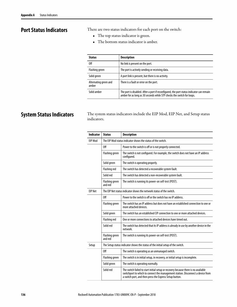
Appendix A Status Indicators
Port Status Indicators There are two status indicators for each port on the switch:• The top status indicator is green.• The bottom status indicator is amber.
System Status Indicators The system status indicators include the EIP Mod, EIP Net, and Setup status indicators.
Status Description
Off No link is present on the port.
Flashing green The port is actively sending or receiving data.
Solid green A port link is present, but there is no activity.
Alternating green and amber
There is a fault or error on the port.
Solid amber The port is disabled. After a port if reconfigured, the port status indicator can remain amber for as long as 30 seconds while STP checks the switch for loops.
Indicator Status Description
EIP Mod The EIP Mod status indicator shows the status of the switch.
Off Power to the switch is off or is not properly connected.
Flashing green The switch is not configured. For example, the switch does not have an IP address configured.
Solid green The switch is operating properly.
Flashing red The switch has detected a recoverable system fault.
Solid red The switch has detected a non-recoverable system fault.
Flashing green and red
The switch is running its power-on self-test (POST).
EIP Net The EIP Net status indicator shows the network status of the switch.
Off Power to the switch is off or the switch has no IP address.
Flashing green The switch has an IP address but does not have an established connection to one or more attached devices.
Solid green The switch has an established CIP connection to one or more attached devices.
Flashing red One or more connections to attached devices have timed out.
Solid red The switch has detected that its IP address is already in use by another device in the network.
Flashing green and red
The switch is running its power-on self-test (POST).
Setup The Setup status indicator shows the status of the initial setup of the switch.
Off The switch is operating as an unmanaged switch.
Flashing green The switch is in initial setup, in recovery, or initial setup is incomplete.
Solid green The switch is operating normally.
Solid red The switch failed to start initial setup or recovery because there is no available switchport to which to connect the management station. Disconnect a device from a switch port, and then press the Express Setup button.
136 Rockwell Automation Publication 1783-UM009C-EN-P - September 2018

Appendix B
Data Types
In the Studio 5000 Logix Designer® application, predefined tags for Input and Output data types have a structure that corresponds to the switch selected when it was added to the I/O tree. Its members are named in accordance with the port names.
You can disable a switch port by setting the corresponding bit in the output tag. The output bits are applied every time that the switch receives the output data from the controller when the controller is in Run mode. When the controller is in Program mode, the output bits are not applied.
The port is enabled if the corresponding output bit is 0. If you enable or disable a port by using Device Manager or the CLI, the port setting can be overridden by the output bits the next time they are applied. The output bits always take precedence, regardless of whether Device Manager or the CLI is used to enable or disable the port.
The following tables list module-defined data types for Stratix® 2500 switches. The tables include information for input (I) and output (O).
Topic Page
1783-LMS5 Data Types 138
1783-LMS8 Data Types 139
Rockwell Automation Publication 1783-UM009C-EN-P - September 2018 137

Appendix B Data Types
1783-LMS5 Data Types Table 65 - Input Data Types
AB:STRATIX_2500_5PORT_MANAGED:I:0
Member Name Type Default Display Style
Valid Values
Fault DINT Binary
AnyPortConnected BOOL Decimal LinkStatus:0
PortFa1_1Connected BOOL Decimal LinkStatus:1
PortFa1_2Connected BOOL Decimal LinkStatus:2
PortFa1_3Connected BOOL Decimal LinkStatus:3
PortFa1_4Connected BOOL Decimal LinkStatus:4
PortFa1_5Connected BOOL Decimal LinkStatus:5
AnyPortUnauthorizedDevice BOOL Decimal UnauthorizedDevice:0
PortFa1_1UnauthorizedDevice BOOL Decimal UnauthorizedDevice:1
PortFa1_2UnauthorizedDevice BOOL Decimal UnauthorizedDevice:2
PortFa1_3UnauthorizedDevice BOOL Decimal UnauthorizedDevice:3
PortFa1_4UnauthorizedDevice BOOL Decimal UnauthorizedDevice:4
PortFa1_5UnauthorizedDevice BOOL Decimal UnauthorizedDevice:5
AnyPortThreshold BOOL Decimal ThresholdExceeded:0
PortFa1_1Threshold BOOL Decimal ThresholdExceeded:1
PortFa1_2Threshold BOOL Decimal ThresholdExceeded:2
PortFa1_3Threshold BOOL Decimal ThresholdExceeded:3
PortFa1_4Threshold BOOL Decimal ThresholdExceeded:4
PortFa1_5Threshold BOOL Decimal ThresholdExceeded:5
AllPortsUtilization SINT Decimal
PortFa1_1Utilization SINT Decimal
PortFa1_2Utilization SINT Decimal
PortFa1_3Utilization SINT Decimal
PortFa1_4Utilization SINT Decimal
PortFa1_5Utilization SINT Decimal
MajorAlarmRelay BOOL Decimal AlarmRelay:0
MulticastGroupActive DINT Binary
Table 66 - Output Data Types
AB:STRATIX_2500_5PORT_MANAGED:O:0
Member Name Type Default Display Style
Valid Values
AllPortsDisabled BOOL Decimal DisablePort:0
PortFa1_1Disable BOOL Decimal DisablePort:1
PortFa1_2Disable BOOL Decimal DisablePort:2
PortFa1_3Disable BOOL Decimal DisablePort:3
PortFa1_4Disable BOOL Decimal DisablePort:4
PortFa1_5Disable BOOL Decimal DisablePort:5
138 Rockwell Automation Publication 1783-UM009C-EN-P - September 2018

Data Types Appendix B
1783-LMS8 Data Types Table 67 - Input Data Types
AB:STRATIX_2500_8PORT_MANAGED:I:0
Member Name Type Default Display Style
Valid Values
Fault DINT Binary
AnyPortConnected BOOL Decimal LinkStatus:0
PortFa1_1Connected BOOL Decimal LinkStatus:1
PortFa1_2Connected BOOL Decimal LinkStatus:2
PortFa1_3Connected BOOL Decimal LinkStatus:3
PortFa1_4Connected BOOL Decimal LinkStatus:4
PortFa1_5Connected BOOL Decimal LinkStatus:5
PortFa1_6Connected BOOL Decimal LinkStatus:6
PortFa1_7Connected BOOL Decimal LinkStatus:7
PortFa1_8Connected BOOL Decimal LinkStatus:8
AnyPortUnauthorizedDevice BOOL Decimal UnauthorizedDevice:0
PortFa1_1UnauthorizedDevice BOOL Decimal UnauthorizedDevice:1
PortFa1_2UnauthorizedDevice BOOL Decimal UnauthorizedDevice:2
PortFa1_3UnauthorizedDevice BOOL Decimal UnauthorizedDevice:3
PortFa1_4UnauthorizedDevice BOOL Decimal UnauthorizedDevice:4
PortFa1_5UnauthorizedDevice BOOL Decimal UnauthorizedDevice:5
PortFa1_6UnauthorizedDevice BOOL Decimal UnauthorizedDevice:6
PortFa1_7UnauthorizedDevice BOOL Decimal UnauthorizedDevice:7
PortFa1_8UnauthorizedDevice BOOL Decimal UnauthorizedDevice:8
AnyPortThreshold BOOL Decimal ThresholdExceeded:0
PortFa1_1Threshold BOOL Decimal ThresholdExceeded:1
PortFa1_2Threshold BOOL Decimal ThresholdExceeded:2
PortFa1_3Threshold BOOL Decimal ThresholdExceeded:3
PortFa1_4Threshold BOOL Decimal ThresholdExceeded:4
PortFa1_5Threshold BOOL Decimal ThresholdExceeded:5
PortFa1_6Threshold BOOL Decimal ThresholdExceeded:6
PortFa1_7Threshold BOOL Decimal ThresholdExceeded:7
PortFa1_8Threshold BOOL Decimal ThresholdExceeded:8
AllPortsUtilization SINT Decimal
PortFa1_1Utilization SINT Decimal
PortFa1_2Utilization SINT Decimal
PortFa1_3Utilization SINT Decimal
PortFa1_4Utilization SINT Decimal
PortFa1_5Utilization SINT Decimal
PortFa1_6Utilization SINT Decimal
PortFa1_7Utilization SINT Decimal
Rockwell Automation Publication 1783-UM009C-EN-P - September 2018 139

Appendix B Data Types
PortFa1_8Utilization SINT Decimal
MajorAlarmRelay BOOL Decimal AlarmRelay:0
MulticastGroupActive DINT Binary
Table 68 - Output Data Types
AB:STRATIX_2500_8PORT_MANAGED:O:0
Member Name Type Default Display Style
Valid Values
AllPortsDisabled BOOL Decimal DisablePort:0
PortFa1_1Disable BOOL Decimal DisablePort:1
PortFa1_2Disable BOOL Decimal DisablePort:2
PortFa1_3Disable BOOL Decimal DisablePort:3
PortFa1_4Disable BOOL Decimal DisablePort:4
PortFa1_5Disable BOOL Decimal DisablePort:5
PortFa1_6Disable BOOL Decimal DisablePort:6
PortFa1_7Disable BOOL Decimal DisablePort:7
PortFa1_8Disable BOOL Decimal DisablePort:8
Table 67 - Input Data Types (continued)
AB:STRATIX_2500_8PORT_MANAGED:I:0
Member Name Type Default Display Style
Valid Values
140 Rockwell Automation Publication 1783-UM009C-EN-P - September 2018

Appendix C
Port Assignments for CIP Data
The following tables identify the instance numbers of the Ethernet link objects that are associated with each port on the switch. Instance 0 does not apply to all ports as it does for bitmaps.
The bit numbers identify each port when they are contained in a structure of all ports, such as in the output assembly. Bit 0 refers to any or all ports.
Topic Page
1783-LMS5 Port Assignments 142
1783-LMS8 Port Assignments 142
Rockwell Automation Publication 1783-UM009C-EN-P - September 2018 141

Appendix C Port Assignments for CIP Data
1783-LMS5 Port Assignments
1783-LMS8 Port Assignments
Bit Port
0 Any/All ports
1 Fa1/1
2 Fa1/2
3 Fa1/3
4 Fa1/4
5 Fa1/5
Bit Port
0 Any/All ports
1 Fa1/1
2 Fa1/2
3 Fa1/3
4 Fa1/4
5 Fa1/5
6 Fa1/6
7 Fa1/7
8 Fa1/8
142 Rockwell Automation Publication 1783-UM009C-EN-P - September 2018

Appendix D
Port Numbering
The port ID consists of the following:• Port type (Fast Ethernet for 10/100 Mbps ports)• Unit number (always 1)• Port number (1…8, depending on the catalog number)
Fast Ethernet is abbreviated as Fa.
Topic Page
1783-LMS5 Port Numbering 144
1783-LMS8 Port Numbering 144
Rockwell Automation Publication 1783-UM009C-EN-P - September 2018 143

Appendix D Port Numbering
1783-LMS5 Port Numbering
1783-LMS8 Port Numbering
Port Numbering on Switch Labels Port Numbering in config.txt Text File
1 Fa1/1
2 Fa1/2
3 Fa1/3
4 Fa1/4
5 Fa1/5
Port Numbering on Switch Labels Port Numbering in config.txt Text File
1 Fa1/1
2 Fa1/2
3 Fa1/3
4 Fa1/4
5 Fa1/5
6 Fa1/6
7 Fa1/7
8 Fa1/8
144 Rockwell Automation Publication 1783-UM009C-EN-P - September 2018

Appendix E
Cables and Connectors
This appendix describes how to connect to Stratix® 2500 ports.
Topic Page
10/100 Ports 146
Connect to 10BASE-T- and 100BASE-TX-Compatible Devices 146
Rockwell Automation Publication 1783-UM009C-EN-P - September 2018 145

Appendix E Cables and Connectors
10/100 Ports The 10/100 Ethernet ports use standard RJ45 connectors and Ethernet pinouts with internal crossovers.
Figure 4 - 10/100 Connector Pinouts
Connect to 10BASE-T- and 100BASE-TX-Compatible Devices
The auto-MDIX feature is enabled by default. Follow these cabling guidelines when the auto-MDIX feature has been disabled.
When connecting the ports to 10BASE-T- and 100BASE-TX-compatible devices, such as servers and routers, you can use a two or four twisted-pair, straight-through cable that is wired for 10BASE-T and 100BASE-TX.
To identify a crossover cable, compare the two modular ends of the cable. Hold the cable ends side by side, with the tab at the back. The color of the wire that is connected to the pin on the outside of the left plug must differ in color from the wire that is connected to the pin on the inside of the right plug.
Figure 5 and Figure 6 show the cable schematics.
Figure 5 - Two Twisted-pair Straight-through Cable Schematics
Figure 6 - Four Twisted-pair Straight-through Cable Schematics
2 31 4 5 6 7 8Pin Label
1
2
3
4
5
6
7
8
RD+
RD-
TD+
NC
NC
TD-
NC
NC
Switch
3 TD+
6 TD–
1 RD+
2 RD–
Router or Personal Computer
3 RD+6 RD–
1 TD+2 TD–
1 TPO+
2 TPO-
3 TP1+
6 TP1-
1 TP1+
Switch Router or Personal Computer
2 TP1-
3 TPO+
6 TPO-
4 TP2+
5 TP2-
7 TP3+
8 TP3-
4 TP3+
5 TP3-
7 TP2+
8 TP2-
146 Rockwell Automation Publication 1783-UM009C-EN-P - September 2018
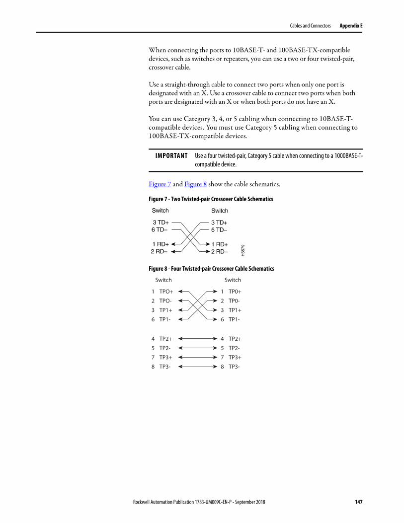
Cables and Connectors Appendix E
When connecting the ports to 10BASE-T- and 100BASE-TX-compatible devices, such as switches or repeaters, you can use a two or four twisted-pair, crossover cable.
Use a straight-through cable to connect two ports when only one port is designated with an X. Use a crossover cable to connect two ports when both ports are designated with an X or when both ports do not have an X.
You can use Category 3, 4, or 5 cabling when connecting to 10BASE-T-compatible devices. You must use Category 5 cabling when connecting to 100BASE-TX-compatible devices.
Figure 7 and Figure 8 show the cable schematics.
Figure 7 - Two Twisted-pair Crossover Cable Schematics
Figure 8 - Four Twisted-pair Crossover Cable Schematics
IMPORTANT Use a four twisted-pair, Category 5 cable when connecting to a 1000BASE-T-compatible device.
Switch
3 TD+6 TD–
1 RD+2 RD–
Switch
3 TD+6 TD–
1 RD+2 RD–
H55
79
1 TPO+
2 TPO-
3 TP1+
6 TP1-
1 TP0+
Switch Switch
2 TP0-
3 TP1+
6 TP1-
4 TP2+
5 TP2-
7 TP3+
8 TP3-
4 TP2+
5 TP2-
7 TP3+
8 TP3-
Rockwell Automation Publication 1783-UM009C-EN-P - September 2018 147

Appendix E Cables and Connectors
Notes:
148 Rockwell Automation Publication 1783-UM009C-EN-P - September 2018

Index
Numerics802.1X 52
AAAA validation method
local 42radius-local 42tacacs-local 42
accessDevice Manager 30, 50release notes 7
Access mode, port 34access VLAN 34acknowledge alarm 112active image 48add
controller project 35Device Manager user 42EtherChannel 68MST instance 96port to VLAN 101SNMP community string 83SNMP group 87SNMP trap recipients 82SNMP user 85VLAN 101, 103
address aliasing 71address, gateway 40address, IP 17, 20, 24, 25, 27, 130administrative user 25agent
PnP 22agent, SNMP 79alarm
acknowledge 112configure 54junction temperature 53switch temperature 53system 111
alert log 117autonegotiation 34, 41
Bbackup image 48bootstrap protocol, BOOTP 61BPDU 16BPDU Filtering 93BPDU Guard 93browser requirements 29button, Express Setup 17
Ccables
crossover 146, 147damaged 129Ethernet 129straight-through 146, 147
CIPabout 10data 12enable 16enable on VLAN 25
CIP security timeout 25CIP status 115CLI
access via SSH 25, 50, 134communication to controller 38community string, SNMP 83configuration file
manage in Device Manager 44manage in Logix Designer application 46
configuration, out-of-the-box 16configure
802.1X 52alarms 54connection properties 38DHCP persistence 57, 62EtherChannels 66general switch properties 36IGMP snooping 71IP address settings 39, 40IP settings 27network settings 23, 26port mirroring 73port security 75port settings 32ports 41QoS priority 78Smartports 89SNMP 79storm control 98STP 92tacacs/radius server 99VLAN 100
connectionCIP 10Data 37Input Data 37properties 38unicast 38
connectors and cables10/100 ports 146, 147
control, storm 98controller project 35CPU utilization 108crossover cable
identify 146pinout 147
customizationDHCP server 57, 62IP address
DHCP IP address pool 59, 64
Rockwell Automation Publication 1783-UM009C-EN-P - September 2018 149

Index
switch port 61, 65IP address (for connected devices) 57, 62
Ddashboard, Device Manager 106data connection password 37data type 137default
login credentials 20default gateway 64default router 59delete
Device Manager user 42EtherChannel 68PnP profile 24SNMP group 87SNMP user 85VLAN 101, 103
delete PnP profile 24Device Manager
about 29access 30, 50hardware requirements 29software requirements 29troubleshoot 131user 42
DHCPIP address assignment 24, 27, 40, 65IP address pool, Device Manager 58IP address pool, Logix Designer 63persistence 56port configurations, Device Manager 60troubleshoot 130
DHCP persistence behavior 57DHCP snooping
Device Manager 60Logix Designer 62
diagnostics, port 124disable 38
BPDU filter 96BPDU Guard 96junction temperature alarm 55keying 37port 41, 137port error recovery 96port security 75switch temperature alarm 55traps 84
DNS address 64DNS server 40DNS server1 and 2 59domain name 40, 59, 64Dot 1x 53download
configuration file 45EDS file 11publications 8release notes 7software update 48
Duplex mode 34
Eedit
Device Manager user 42EtherChannel 68SNMP group 87SNMP user 85VLAN 101, 103
EDS file 11EIP Mod status indicator 136EIP Net status indicator 136electronic keying 37enable
802.1X 53BPDU Filter 16BPDU Guard 16CIP 16, 25DHCP snooping, Device Manager 60DHCP snooping, Logix Designer 62MSTP 16port security 75POST 128QoS priority 78storm control 98traps 84
encryption 16entry, system log 119EtherChannels
about 66configure via Logix Designer application 69example 66
Ethernet cable 129EtherNet/IP CIP interface 10EtherNet/IP network 10, 127EtherNet/IP protocol 89, 115explicit messaging 10Express Setup
about 16button 17Device Manager 23Logix Designer application 27Long Press mode 22Medium Press mode 21modes 18requirements 18Short Press mode 19
Ffactory default settings 22fault, major 38fault, module 38features
hardware 13software 13
file, configuration 44, 46file, EDS 11firmware update, troubleshoot 133front panel 106Full-duplex mode 34
150 Rockwell Automation Publication 1783-UM009C-EN-P - September 2018

Index
Ggateway address 40global settings, 802.1X 53group, SNMP 86
HHalf-duplex mode 34hardware features 13hardware requirements
Device Manager 29host name 40HTTP 16, 44, 48HTTPS 16Hybrid mode, port 34
IIGMP snooping
about 71address aliasing 71configure via Device Manager 72
imageactive 48backup 48
implicit messaging 10indicator
Setup status 18setup status 18
indicatorsport status 136system status 136
individual port administration802.1X 53
inhibit module 38Input Data connection 37input data types 137installation instructions 8installation options 9, 16instructions, installation 8IP address 40
assignment mode 24CIP 25computer 20customization
connected devices 57DHCP IP address pool 59, 64switch port 61, 65
DHCP 27DHCP IP address pool
ending range 59, 64starting range 59, 64
switch port 61, 65assigning 61deleting 61modifying 61
troubleshoot 130IP assignment mode 24, 40
Jjunction temperature 53
Kkeying, electronic 37
Llease length 59LED.See status indicatorslimits, MAC address 74link status 130local
AAA validation method 42log, system 117Logix Designer
DHCP persistence 62Logix Designer application
about 35Long Press mode Express Setup 18, 22
MMAC address limits 74major fault 38management interface 29management protocol 16management VLAN 28, 101manager, SNMP 79Medium Press mode Express Setup 18, 21messages 10
explicit 10implicit 10SNMP 84system log 117
MIB 80mirroring, port 73mismatch prevention, Smartports 90mode
Access 89EtherChannel 66, 68Express Setup 18IP assignment 24Protect 74Restrict 74Shutdown 74STP 93Trunk 89
module fault 38module information 122module, inhibit 38module-defined data type 137
Rockwell Automation Publication 1783-UM009C-EN-P - September 2018 151

Index
monitoralert log 117CIP status 115front panel 106module information 122port diagnostics 124port mirroring 73port security 113port statistics 112port status 123port utilization 109status indicators 128switch health 108switch status 120system alarm 111
MST instance 96MSTP 16
Nnative VLAN 34network access
tacacs/radius 99network settings
configure via Device Manager 23configure via Logix Designer application 26
NTP server 25, 27
Oout-of-the-box configuration 16output data types 137
Ppassword
administrative user 25CIP security 26data connection 37
persistenceDHCP 56
persistence behaviorDHCP 57
ping utilitystatistics 119
pinoutcrossover cable 147RJ45 connector 146straight-through cable 146
Plug and Play 22PnP 22
agent 22PnP profile
delete 24PnP server 25pool name 59, 61, 64port
configure via Device Manager 32configure via Logix Designer application 41enable/disable 34
port administrative mode 34
port assignments for CIP data 141, 143port diagnostics 124port Duplex mode 34port mirroring
about 73configure via Device Manager 73
port numbering 34port security 74, 75port security statistics 113port settings 130port speed 34port statistics 112port status 123port status indicators 136port utilization 109PortFast 93POST 128Primary DNS server 25profile
delete PnP 24project, controller 35properties, connection 38Protect mode 74protocol
HTTPS 16IGMP 71management 16SNMP 16SSH 16STP 92
PTP 78
QQoS
about 78configure via Device Manager 78
quierer, IGMP snooping 71
Rradius security protocol 99radius-local
AAA validation method 42recovery
firmware update 133release notes 7requested packet interval 38requirements
Device Manager 29Express Setup 18web browser 29
reset switch 132restart switch
via Device Manager 131, 132via Logix Designer application 131, 133with factory defaults 22
restore connection 130Restrict mdoe 74
152 Rockwell Automation Publication 1783-UM009C-EN-P - September 2018

Index
revision, switch 37RJ45 connector
pinout 146roles, Smartport 89RSLinx software 11RSWho 11
SSecondary DNS server 25security modes, port security 74security, CIP 25security, port 113
configure via Device Manager 75configure via Logix Designer application 77
server configurationtacacs/radius 99
server, DNS 40server, NTP 25, 27server, PnP 25server, Primary DNS 25server, Secondary DNS 25settings, factory default 22, 131Setup status indicator 18, 19, 21, 22, 136Short Press mode Express Setup 18, 19Shutdown mode 74Smartports
about 89assign via Device Manager 90assign via Logix Designer application 91mismatch prevention 90VLAN assignment 91
SNMP 16about 79agent 79community string 83configure via Device Manager 81group 86manager 79MIB 80system options 82traps 84user 85view 85
snoopingDHCP, Device Manager 60DHCP, Logix Designer 62IGMP 71
snooping, IGMP 71software
Device Manager requirements 29features 13RSLinx 11update 48
software featurescustomization
DHCP server settings 57, 62specifications, switch 8speed, port 34SSH 16, 50, 134
statisticsping 119port 112port security 113
status indicators 128, 135status, CIP 115status, link 130status, port 123status, setup 18status, switch 120sticky MAC 76, 114storm control
about 98configure via Device Manager 98
STPabout 92configure via Device Manager 94modes 93
straight-through cablepinout 146
string, community 83Studio 5000 environment 35subnet mask
DHCP IP address pool 59, 64switch
configure via Device Manager 29configure via Logix Designer application 39install 8monitor 106reset 132restart 131troubleshoot 127
Device Manager 131DHCP 130firmware update 133IP address 130
switch health 108switch information 107switch installation options 9switch IP settings 39switch revision 37switch specifications 8switch status 120switch status indicators 128switch temperature 53SYSLOG 16, 117system alarm 111system log 117system options, SNMP 82system status indicators 136
Ttacacs+ security protocol 99tacas-local
AAA validation method 42technical specifications 8Telnet 16
Rockwell Automation Publication 1783-UM009C-EN-P - September 2018 153

Index
temperaturejunction 53switch 53
TFTP 44, 48timeout, CIP security 25traffic prioritization 78traffic storm 98traps, SNMP 84troubleshoot
Device Manager 131DHCP 130EtherNet/IP network 127firmware update 133IP address 130link status 130port settings 130reset switch 132switch 127
troubleshoot connectivityping 119
Trunk mode, port 34
Uunicast connection 38update, software 48upload
configuration file 44, 46EDS file 11
useradd 42administrative password 25delete 42edit 42password 43privilege 43SNMP 85validation 42
utiilityping 119
Vvalidating users
AAA method 42view, SNMP 85violation, security 74VLAN
access 34add port 101configure via Device Manager 101configure via Logix Designer application 102enable CIP 25management VLAN 40, 101native 34
Wweb browser requirements 29
154 Rockwell Automation Publication 1783-UM009C-EN-P - September 2018


Publication 1783-UM009C-EN-P - September 2018Supersedes Publication 1783-UM009B-EN-P June 2018 Copyright © 2018 Rockwell Automation, Inc. All rights reserved. Printed in the U.S.A.
Rockwell Automation SupportUse the following resources to access support information.
Documentation FeedbackYour comments will help us serve your documentation needs better. If you have any suggestions on how to improve this document, complete the How Are We Doing? form at http://literature.rockwellautomation.com/idc/groups/literature/documents/du/ra-du002_-en-e.pdf.
Technical Support Center Knowledgebase Articles, How-to Videos, FAQs, Chat, User Forums, and Product Notification Updates. https://rockwellautomation.custhelp.com/
Local Technical Support Phone Numbers Locate the phone number for your country. http://www.rockwellautomation.com/global/support/get-support-now.page
Direct Dial Codes Find the Direct Dial Code for your product. Use the code to route your call directly to a technical support engineer. http://www.rockwellautomation.com/global/support/direct-dial.page
Literature Library Installation Instructions, Manuals, Brochures, and Technical Data. http://www.rockwellautomation.com/global/literature-library/overview.page
Product Compatibility and Download Center (PCDC)
Get help determining how products interact, check features and capabilities, and find associated firmware. http://www.rockwellautomation.com/global/support/pcdc.page
.
Rockwell Otomasyon Ticaret A.Ş., Kar Plaza İş Merkezi E Blok Kat:6 34752 İçerenköy, İstanbul, Tel: +90 (216) 5698400
Rockwell Automation maintains current product environmental information on its website at http://www.rockwellautomation.com/rockwellautomation/about-us/sustainability-ethics/product-environmental-compliance.page.
Allen-Bradley, Rockwell Automation, Rockwell Software, RSLinx, RSLogix 5000, RSNetWorx, Stratix, Studio 5000, and Studio 5000 Logix Designer are trademarks of RockwellAutomation, Inc.
Trademarks not belonging to Rockwell Automation are property of their respective companies.