strategies, protections, and mitigations for the electric ... · pdf filestrategies,...
TRANSCRIPT

The INL is a U.S. Department of Energy National Laboratory operated by Battelle Energy Alliance
INL/EXT-15-35582
Strategies, Protections, and Mitigations for the Electric Grid from Electromagnetic Pulse Effects
January 2016

ii
DISCLAIMER This information was prepared as an account of work sponsored by
an agency of the U.S. Government. Neither the U.S. Government nor any agency thereof, nor any of their employees, makes any warranty, expressed or implied, or assumes any legal liability or responsibility for the accuracy, completeness, or usefulness, of any information, apparatus, product, or process disclosed, or represents that its use would not infringe privately owned rights. References herein to any specific commercial product, process, or service by trade name, trade mark, manufacturer, or otherwise, does not necessarily constitute or imply its endorsement, recommendation, or favoring by the U.S. Government or any agency thereof. The views and opinions of authors expressed herein do not necessarily state or reflect those of the U.S. Government or any agency thereof.

iii
INL/EXT-15-35582
Strategies, Protections, and Mitigations for the Electric Grid from Electromagnetic Pulse Effects
January 2016
Idaho National Laboratory Idaho Falls, Idaho 83415
http://www.inl.gov
Prepared for the U.S. Department of Energy
Office of Electricity Delivery and Energy Reliability Under DOE Idaho Operations Office
Contract DE-AC07-05ID14517

iv
EXECUTIVE SUMMARY The mission of the Department of Energy’s (DOE) Office of Electricity Delivery and Energy Reliability (OE) is to lead national efforts to modernize the electricity delivery system, enhance the security and reliability of America’s energy infrastructure, and facilitate recovery from disruptions to the energy supply. One of the threats OE is concerned about is a high-altitude electromagnetic pulse (HEMP) from a nuclear explosion and electromagnetic pulse (EMP) or an early time (E1) pulse which can be generated by EMP weapons. Idaho National Laboratory (INL) was chosen to conduct the EMP study for DOE-OE due to its capabilities and experience in setting up EMP experiments on the electric grid, conducting vulnerability assessments, and developing innovative technologies to increase infrastructure resiliency. This report identifies known grid impacts from EMP threats, effectiveness, and potential costs of known mitigations, areas for government and private partnerships in better protecting the electric grid, and gaps in knowledge and protection strategy.
Many sources and references were analyzed for this report and were found lacking due to the age of the tests, general lack of data, use of non-energized configurations, and lack of modern grid technologies. Most sources on the impact of EMP to electric power grids are decades old and include only “observation level” information. References on past experimentation performed to understand EMP impacts to electric power grids had very limited test configurations (non-energized and/or small-scale), and were missing modern electric grid technologies including communication technologies for control of the grid. Most mitigation advice does not take into account protections from all EMP pulses (E1, E2, and E3) and, if applied, would cause unintended gaps in protection for other energy pulses (i.e., geomagnetic or lightning caused). In summary, there are more unknowns than knowns causing industry to question where to focus EMP protection investments and the efficacy of applying such protections.
Identified EMP mitigation and protection measures include placing assets in a faraday cage; using hardened electronics, grounding outdoor assets, and utilizing fiber optic cable for communications; installing surge arresters; and applying load filters and spark gap technologies. Applying these mitigations to all assets is impractical due to the size and distribution of electric grid resources and cost of application. Restoration and recovery are commonly the focus due to this impracticality, and applying mitigations to the assets essential for restoration will be critical in enabling recovery.
Effectiveness measures are challenging to assess due to the old observation-based information from past EMP tests, limited availability of experimentation data, and conflicting protection goals between the different EMP pulse types. Baselining the threat, impacts to the grid, and effectiveness of the mitigations for all EMP pulses is needed to develop informed methodologies which will be most effective to the electric power industry.
Strategies for applying EMP mitigations to the electric grid include characterizing the threat based on current and expected (nuclear and EMP) weapons in the inventory of potential adversaries (not on U.S. or Soviet nuclear weapons from the 1960s or 1970s), baselining the impact of EMP on modern grid technologies, baselining the mitigations, and sharing results to inform methods and toolsets for utilities to do their own trade-off analyses for protecting against the EMP threat.
Research gaps identified include impact on modern grid technologies, communications (especially wireless), mitigation to match new emerging EMP weapons, heuristic tools for utilities to apply mitigations to the most critical assets for recovery operations, methods to store and maintain spares for recovery, and national exercises for industry and government to understand the interdependencies of localized or large-scale restoration and recovery.
v
Contents 1. INTRODUCTION .............................................................................................................................. 1
1.1 Purpose .................................................................................................................................. 1
1.1.1 Problem Statement .............................................................................................. 1 2. Threat Problem Set ............................................................................................................................. 3
2.1 Known EMP Threats ............................................................................................................. 5
2.1.1 Nuclear EMP ....................................................................................................... 5 2.1.2 Non-Nuclear EMP ............................................................................................... 6
2.2 Unknown EMP Threats ......................................................................................................... 6
2.2.1 What are the EMP Impacts to Modern Critical Infrastructure? .......................... 6 2.2.2 What are the Differences in EMP Delivery and Generation? ............................. 6
3. Knowns and Unknowns for EMP Effects on the Electric Grid Assets .............................................. 6
3.1 Known Electric Grid Impacts ................................................................................................ 6
3.1.1 No Empirical Data Exists for Electric Grid Assets ............................................. 7 3.1.2 Attenuation of EMP via Long Metal Structures .................................................. 7 3.1.3 EMP Hardening Rare for Chip Sets .................................................................... 7 3.1.4 Communications Disruption ............................................................................... 7 3.1.5 Embedded Systems Damage ............................................................................... 7
3.2 Unknowns of Electric Grid Impacts ...................................................................................... 8
3.2.1 Are Different Communications Media More or Less Susceptible to EMP? ....... 8 3.2.2 Are Different Chip Sets More or Less Susceptible to EMP? .............................. 8 3.2.3 Where Is the Empirical Data for Generation? ..................................................... 8 3.2.4 Where Is the Empirical Data for Transmission? ................................................. 9
4. Mitigation to Electric Grid ................................................................................................................. 9
4.1 Known Mitigation ................................................................................................................. 9
4.1.1 Properly Designed Shielding Works ................................................................... 9 4.1.2 Maintenance of Shielding Essential .................................................................... 9
4.2 Unknown Mitigation ............................................................................................................. 9
4.2.1 How Significant is the Current Threat? ............................................................... 9 4.2.2 How Many Restoration Assets are Needed? ..................................................... 10 4.2.3 Mitigation Interaction Between Pulses? ............................................................ 10
5. Sources ............................................................................................................................................. 10
5.1 Survey of Reference Materials ............................................................................................ 10
5.2 Survey of Testing and Experimentation .............................................................................. 11
5.3 Other Sources ...................................................................................................................... 12
6. Standards and Guidance ................................................................................................................... 13
vi
6.1 User Applicability and Context ........................................................................................... 13
6.2 Military Standards ............................................................................................................... 13
6.3 ANSI/IEEE Standards ......................................................................................................... 14
6.4 IEC Standards ...................................................................................................................... 14
6.5 ISO Standards ...................................................................................................................... 15
6.6 UL Standards for Electromagnetic Radiation ...................................................................... 15
6.7 Scope of Guidance ............................................................................................................... 15
6.8 Relevancy to Bulk Electric System ..................................................................................... 15
7. Protection and Mitigation ................................................................................................................. 15
7.1 Protection and Mitigation Cost and Effectiveness .............................................................. 15
7.1.1 Context of Protections ....................................................................................... 15 7.1.2 Cost and Effectiveness ...................................................................................... 17
7.2 Case Study: Protections in Use ............................................................................................ 19
7.2.1 Proof of Effectiveness ....................................................................................... 19 7.2.2 Protection Strategy Methods and Technology for the Electric Grid ................. 19 7.2.3 High Protection Application Use Case .............................................................. 20 7.2.4 Medium Protection Application Use Case ........................................................ 20 7.2.5 Low Protection Application Use Case .............................................................. 20
8. Role for Government and Electric Grid Owners/Operators ............................................................. 21
8.1 Actions and Future Government Role ................................................................................. 21
8.2 Actions and Future Electric Grid Industry Role .................................................................. 22
8.3 Common Areas for Partnerships.......................................................................................... 23
9. Conclusion ........................................................................................................................................ 23
9.1 Discussion of Gaps .............................................................................................................. 23
9.1.1 Reference Material ............................................................................................ 23 9.1.2 Standards and Guidance .................................................................................... 23 9.1.3 Protection and Mitigation .................................................................................. 23
9.2 Future Direction Discussion ................................................................................................ 23
APPENDIX A: Reference Material Summary ............................................................................................ 24
APPENDIX B: Reference material Standards and Guidance ..................................................................... 27
Military Standards ............................................................................................................................ 27
vii
ANSI/IEEE Standards ...................................................................................................................... 27
IEC/TR 61000-5-3 ed1.0 .................................................................................................................. 28
IEC/TR 61000-5-4 ed1.0 .................................................................................................................. 28
IEC/TR 61000-5-5 ed1.0 .................................................................................................................. 28
IEC/TR 61000-5-8 ed1.0 .................................................................................................................. 29
IEC/TR 61000-5-9 ed1.0 .................................................................................................................. 29
IEC/TR 61000-6-6 ed1.0 .................................................................................................................. 29
ISO Standards ................................................................................................................................... 29
UL Standards for Electromagnetic Radiation ................................................................................... 30
APPENDIX C: Test and Experimentation Summary ................................................................................. 31
Consumer Electronics and Communications .................................................................................... 32
FIGURES
Figure 1. HEMP Pulse .................................................................................................................................. 3
Figure 2. Peak Electric Field EMP Nuclear .................................................................................................. 4
Figure 3. IEC Standards .............................................................................................................................. 14
Figure 4. Total Vulnerability Assessment Estimate .................................................................................... 20
ACRONYMS ANSI America National Standards Institute
CHAMP Counter-electronics High-powered Advanced Missile Project
dB Decibels
DOD Department of Defense
DOE Department of Energy
viii
E1 Early time EMP pulse from HEMP or EMP weapon
E2 Intermediate time pulse similar to lightning
E3 Late time pulse similar to GMD (Magnetohydro Dynamic)
EMC Electromagnetic capability
EMI Electromagnetic interference
FCG Flux compression generator
FERC Federal Energy Regulatory Commission
GHZ Giga hertz
GMD Geomagnetic disturbance
HEMP High-altitude electromagnetic pulse
HILF High impact low frequency
HMI Human machine interface
IEC International Electrotechnical Commission
IED Intelligent end device
IEEE Institute of Electrical and Electronics Engineers
IEMI Intentional electromagnetic interference (weapon)
INL Idaho National Laboratory
ISM Industrial, Scientific and Medical RF Band
ISO International Organization for Standardization
kHZ Kilo hertz
kV Kilo volts
MGD Microwave generation device
MIL-STD Military standard
NERC North American Electric Reliability Corporation
ix
OE Office of Electricity Delivery and Energy Reliability – Department of Energy
PLC Programmable logic controller
POE Points of entry
PPD Presidential Policy Directive
RDT&E Research, development, testing, and experimentation
SBEMP Surface burst electromagnetic pulse
SCADA Supervisory control and data acquisition
SEL Schweitzer Engineering Laboratories
UL Underwriters Laboratory
1
1. INTRODUCTION
1.1 Purpose
The mission of the Department of Energy’s (DOE) Office of Electricity Delivery and Energy Reliability (OE) is to lead national efforts to modernize the electricity delivery system, enhance the security and reliability of America’s energy infrastructure, and facilitate recovery from disruptions to the energy supply. One of the threats OE is concerned about is a high-altitude electromagnetic pulse (HEMP) from a nuclear detonation. A Commission to Assess the Threat to the United States from Electromagnetic Pulse (EMP) Attack was established pursuant to the National Defense Authorization Act for fiscal year (FY) 2001. The Commission known as the EMP Commission was reestablished in FY 2006 to continue to assess this threat.a The EMP Commission wrote several reports detailing the potential consequences of an EMP. The Commission was very concerned about the vulnerability of the electric grid to an EMP attack, and several members of the Commission have also reported findings and issued calls for action in the media.b The Federal Energy Regulatory Commission (FERC) also sponsored an EMP report with Oakridge National Laboratory describing past incidences and monitoring techniques for geomagnetic disturbances (GMD).c Additionally, an EMP pulse can be generated by a non-nuclear EMP weapon; these weapons have become more readily available.d Such a pulse can be more powerful than that created by a nuclear weapon, but would have a more localized impact.
HEMP is considered a high impact low frequency (HILF) event.e HILF events were discussed in a DOE and North American Electric Reliability Corporation (NERC) sponsored workshop in 2009. In June 2010, a report was issued on the findings.f As the Sector Specific Agency for the electricity sub-sector and as a technical resource within the federal government for matters of electric power grid operations, OE/Infrastructure Security and Emergency Response (ISER) must provide federal leadership and technical guidance in addressing this issue. This report is a step in addressing concerns over the impact of EMP on the electric power grid.
Idaho National Laboratory (INL) was chosen to conduct this EMP study for DOE-OE due to its capabilities and experience in this area. For over a decade, INL has conducted vulnerability assessments and developed innovative technology to increase infrastructure resiliency.
1.1.1 Problem Statement
The Department of Defense (DOD) funded extensive research, development, testing, and experimentation (RDT&E) of the effects of EMP and other nuclear effects on military assets and facilities during the Cold War era (1947-1991). The objective was to determine what could and should be done to mitigate and protect against these effects to ensure that strategic and tactical military missions could be successfully
a http://www.empcommission.org/docs/A2473-EMP_Commission.pdf bhttp://www.wsj.com/articles/james-woolsey-and-peter-vincent-pry-the-growing-threat-from-an-emp-attack-1407885281 c http://web.ornl.gov/sci/ees/etsd/pes/ferc_emp_gic.shtml d http://www.amazon.com/s/?ie=UTF8&keywords=emp+generator&tag=googhydr-20&index=aps&hvadid= 61737091093&hvpos=1o1&hvexid=&hvnetw=g&hvrand=3111663323466338958&hvpone=&hvptwo=&hvqmt=b&hvdev=c&ref=pd_sl_5yn5iousyk_b e It may be better to refer to EMP as a high impact low probability event. Attacks really do not have a tracked “frequency” like natural hazards; they do have estimated probabilities. f http://www.nerc.com/pa/CI/Resources/Documents/HILF%20Report.pdf

2
carried out, after such an attack. Little has been done to investigate and evaluate how an electric utility could protect itself from, or mitigate the effects of, EMP on its systems. No information exists to describe the impacts of EMP on the newer smart grid technologies, many of which also include multiple types of wireless communications.
Whose responsibility is it for EMP protection? Few utilities have given much thought or effort to protecting their systems against the effects of EMP. Many electric grid owners and operators see protection from an EMP attack as a DOD responsibility. Other owners and operators have taken steps to protect critical control centers and other assets from EMP but without the threat information to know what to protect against or consensus from the energy sector on levels of protections that would be prudent and adequate for recovery.g Many stakeholders, federal and private, have a role to play in better preparing the nation and the electric grid against an EMP attack. Using Presidential Policy Directive 8 (PPD-8) as a framework for preparedness, there is a role in prevention, protection, mitigation, response, and recovery. The federal government, and owners and operators of critical infrastructure systems need to work together to assess the risk of such attack to systems and assets, and then consider the appropriate actions. Once risk is assessed, it can be eliminated, reduced, shared, or accepted. If not eliminated or reduced, stakeholders should have plans to respond to and recover from the consequences that have been accepted, in the event an attack occurs.h Specifics about EMP attacks and protections are not provided in high level documents such as the PPD-8, nor are the lines of responsibility between the private sector and federal government for protections and mitigations provided.
The White House, DOE, Department of State, and Intelligence Community have major roles to play in prevention (and deterrence) of such an attack. The Intelligence Community and the Pentagon each have roles in identifying and eliminating proliferation and nuclear threats.
If such an attack were in fact launched, the Pentagon would have the primary responsibility to destroy the weapon before it exploded over the United States for the protection of the United States. Such defenses can fail, though, requiring asset owners and operators to design protections for their critical assets.
Even if no protection and mitigation measures are in place for an owner/operator, other procedural mitigating measures need to be in place and exercised for the immediate response actions and activities that can reduce losses and speed recovery. In addition, long term recovery plans should be developed and exercised in the event an EMP attack occurs.
This study has three main objectives:
1) Identify and describe possible EMP mitigation and protection measures for utilities to consider (Section 4 and 7)
2) Examine these measures with regard to cost and effectiveness (Section 7.2) 3) Offer some overall strategies/solutions for government/industry partnerships to reduce the
catastrophic effects of an EMP on the commercial bulk electric grid. What can/should the government do? What can/utilities do? (Section 8)
g http://www.breitbart.com/texas/2015/04/19/op-ed-texas-must-protect-our-grid-against-attack-the-feds-wont/ h http://www.fema.gov/media-library-data/1443799615171-2aae90be55041740f97e8532fc680d40/National_Preparedness_Goal_2nd_Edition.pdf
3
2. Threat Problem Set
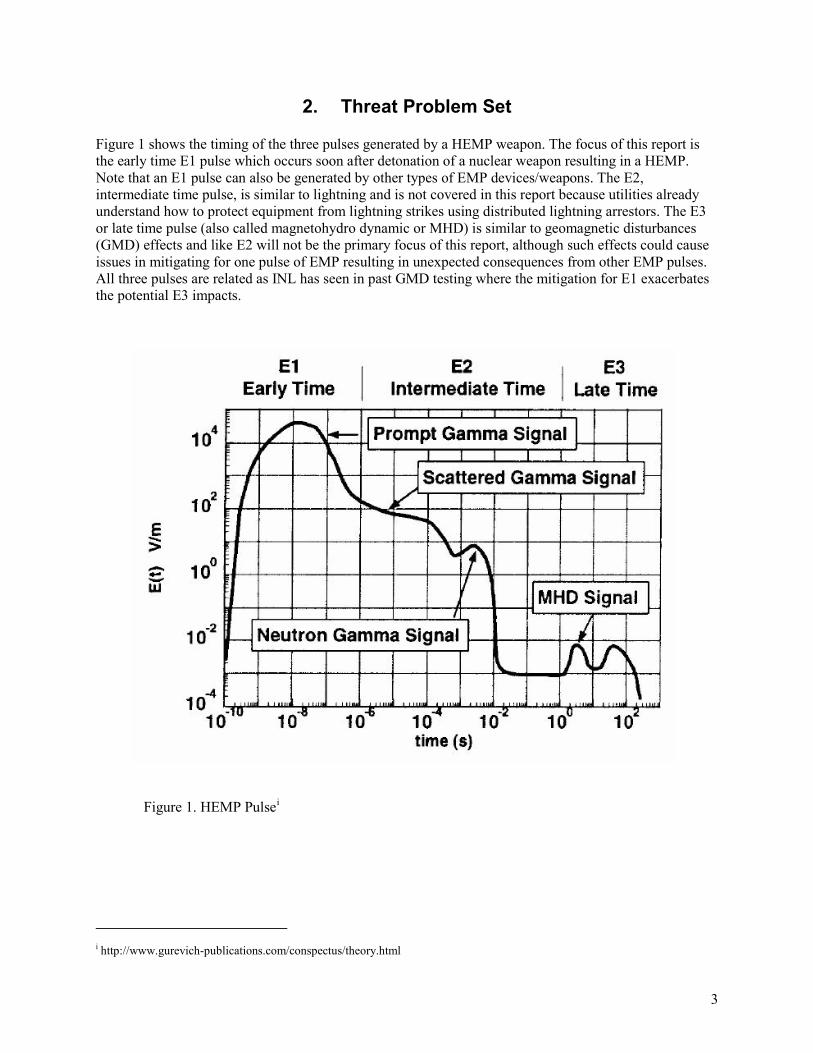
Figure 1 shows the timing of the three pulses generated by a HEMP weapon. The focus of this report is the early time E1 pulse which occurs soon after detonation of a nuclear weapon resulting in a HEMP. Note that an E1 pulse can also be generated by other types of EMP devices/weapons. The E2, intermediate time pulse, is similar to lightning and is not covered in this report because utilities already understand how to protect equipment from lightning strikes using distributed lightning arrestors. The E3 or late time pulse (also called magnetohydro dynamic or MHD) is similar to geomagnetic disturbances (GMD) effects and like E2 will not be the primary focus of this report, although such effects could cause issues in mitigating for one pulse of EMP resulting in unexpected consequences from other EMP pulses. All three pulses are related as INL has seen in past GMD testing where the mitigation for E1 exacerbates the potential E3 impacts.
Figure 1. HEMP Pulsei
i http://www.gurevich-publications.com/conspectus/theory.html
4
EMP can be generated by different methods through nuclear weapons:
• HEMP caused by high altitude (20-400km) detonation of a nuclear device • Air burst EMP weapon 2-20 kilometers up from surface • Surface burst EMP (SBEMP) weapon under .2 kilometers from surface
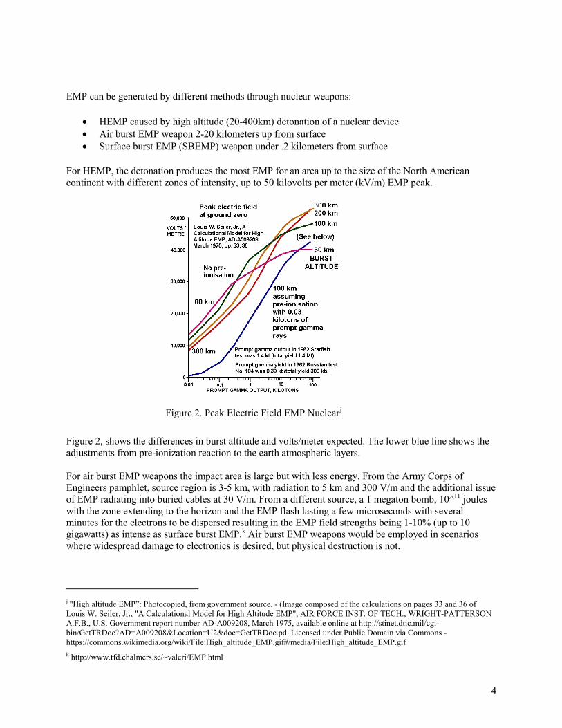
For HEMP, the detonation produces the most EMP for an area up to the size of the North American continent with different zones of intensity, up to 50 kilovolts per meter (kV/m) EMP peak.
Figure 2. Peak Electric Field EMP Nuclearj
Figure 2, shows the differences in burst altitude and volts/meter expected. The lower blue line shows the adjustments from pre-ionization reaction to the earth atmospheric layers. For air burst EMP weapons the impact area is large but with less energy. From the Army Corps of Engineers pamphlet, source region is 3-5 km, with radiation to 5 km and 300 V/m and the additional issue of EMP radiating into buried cables at 30 V/m. From a different source, a 1 megaton bomb, 10^11 joules with the zone extending to the horizon and the EMP flash lasting a few microseconds with several minutes for the electrons to be dispersed resulting in the EMP field strengths being 1-10% (up to 10 gigawatts) as intense as surface burst EMP.k Air burst EMP weapons would be employed in scenarios where widespread damage to electronics is desired, but physical destruction is not.
j "High altitude EMP”: Photocopied, from government source. - (Image composed of the calculations on pages 33 and 36 of Louis W. Seiler, Jr., "A Calculational Model for High Altitude EMP", AIR FORCE INST. OF TECH., WRIGHT-PATTERSON A.F.B., U.S. Government report number AD-A009208, March 1975, available online at http://stinet.dtic.mil/cgi-bin/GetTRDoc?AD=A009208&Location=U2&doc=GetTRDoc.pd. Licensed under Public Domain via Commons - https://commons.wikimedia.org/wiki/File:High_altitude_EMP.gif#/media/File:High_altitude_EMP.gif k http://www.tfd.chalmers.se/~valeri/EMP.html
5
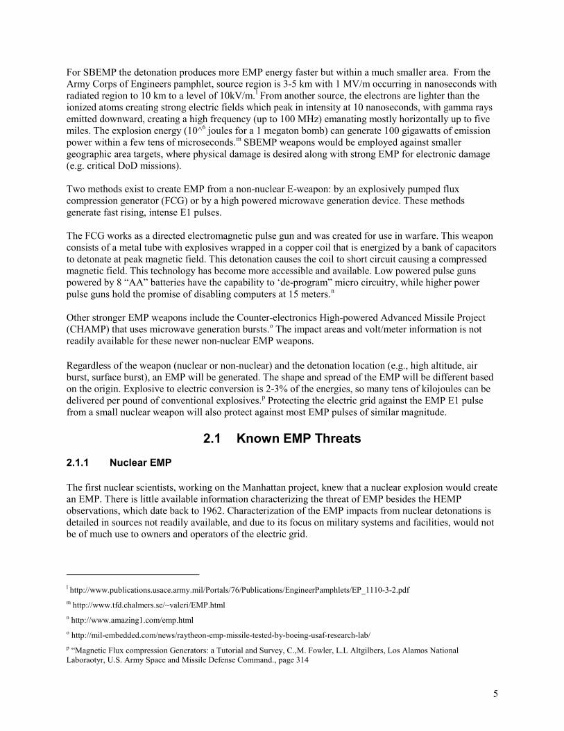
For SBEMP the detonation produces more EMP energy faster but within a much smaller area. From the Army Corps of Engineers pamphlet, source region is 3-5 km with 1 MV/m occurring in nanoseconds with radiated region to 10 km to a level of 10kV/m.l From another source, the electrons are lighter than the ionized atoms creating strong electric fields which peak in intensity at 10 nanoseconds, with gamma rays emitted downward, creating a high frequency (up to 100 MHz) emanating mostly horizontally up to five miles. The explosion energy (10^6 joules for a 1 megaton bomb) can generate 100 gigawatts of emission power within a few tens of microseconds.m SBEMP weapons would be employed against smaller geographic area targets, where physical damage is desired along with strong EMP for electronic damage (e.g. critical DoD missions). Two methods exist to create EMP from a non-nuclear E-weapon: by an explosively pumped flux compression generator (FCG) or by a high powered microwave generation device. These methods generate fast rising, intense E1 pulses. The FCG works as a directed electromagnetic pulse gun and was created for use in warfare. This weapon consists of a metal tube with explosives wrapped in a copper coil that is energized by a bank of capacitors to detonate at peak magnetic field. This detonation causes the coil to short circuit causing a compressed magnetic field. This technology has become more accessible and available. Low powered pulse guns powered by 8 “AA” batteries have the capability to ‘de-program” micro circuitry, while higher power pulse guns hold the promise of disabling computers at 15 meters.n Other stronger EMP weapons include the Counter-electronics High-powered Advanced Missile Project (CHAMP) that uses microwave generation bursts.o The impact areas and volt/meter information is not readily available for these newer non-nuclear EMP weapons.
Regardless of the weapon (nuclear or non-nuclear) and the detonation location (e.g., high altitude, air burst, surface burst), an EMP will be generated. The shape and spread of the EMP will be different based on the origin. Explosive to electric conversion is 2-3% of the energies, so many tens of kilojoules can be delivered per pound of conventional explosives.p Protecting the electric grid against the EMP E1 pulse from a small nuclear weapon will also protect against most EMP pulses of similar magnitude.
2.1 Known EMP Threats
2.1.1 Nuclear EMP
The first nuclear scientists, working on the Manhattan project, knew that a nuclear explosion would create an EMP. There is little available information characterizing the threat of EMP besides the HEMP observations, which date back to 1962. Characterization of the EMP impacts from nuclear detonations is detailed in sources not readily available, and due to its focus on military systems and facilities, would not be of much use to owners and operators of the electric grid.
l http://www.publications.usace.army.mil/Portals/76/Publications/EngineerPamphlets/EP_1110-3-2.pdf m http://www.tfd.chalmers.se/~valeri/EMP.html n http://www.amazing1.com/emp.html o http://mil-embedded.com/news/raytheon-emp-missile-tested-by-boeing-usaf-research-lab/ p “Magnetic Flux compression Generators: a Tutorial and Survey, C.,M. Fowler, L.L Altgilbers, Los Alamos National Laboraotyr, U.S. Army Space and Missile Defense Command., page 314
6
2.1.2 Non-Nuclear EMP
Generalizations from the Army Corps of Engineers are provided in Section 2 above to characterize the magnitude of impact from non-nuclear EMP. A recent Boeing announcement depicted an E-weapon on a drone effectively neutralizing the lights and consumer electronics in a focused area.q
2.2 Unknown EMP Threats
Rapidly developed technology has changed the threat of EMP to include EMP weapons that are commercially available. The impact and differences of these weapons need to be understood so owners and operators know to what level of threat the designed defenses need to protect against.
2.2.1 What are the EMP Impacts to Modern Critical Infrastructure?
The impact of EMP on larger systems (not just critical military load centers), modern control center components and complex control systems, wireless communications common for the control of the electric system, and propagation of EMP across connected infrastructures is unknown.
2.2.2 What are the Differences in EMP Delivery and Generation?
Past experimentation does not accurately characterize the different threats generated by SBEMP, air burst, and non-nuclear EMP Weapons. Further GMD and EMP mitigation strategy tests are needed to understand these sometimes conflicting phenomonologies and their potential impacts on the electric grid.
3. Knowns and Unknowns for EMP Effects on the Electric Grid Assets
The following sections contain mainly anecdotal information due to the lack of available empirical data. One reason for the lack of data is that previous military testing targeted hardened or specialized military components, not the type of components found on the electric grid. The testing reports which are accessible are old, with differing test configurations, but the common observations are listed for generally understood behaviors, impacts, and mitigations of EMP.
3.1 Known Electric Grid Impacts
There are few assumptions generally considered from the review of past and current EMP analysis and experimentation on impacts to electric grids. Based on previous testing, commonly used communications for the electric grid will be disrupted. Based on previous military RDT&E, many chip sets in embedded devices for the grid will likely be damaged based on exposure and device connectivity to wires that act as antennas.
q http://www.cnn.com/videos/us/2015/05/25/orig-boeing-electromagnetic-pulse-weapon.cnn Accessed June 15, 2015.
7
3.1.1 No Empirical Data Exists for Electric Grid Assets
Little or no experimental data exists on energized infrastructure for the electric power grid systems, complex control centers, transmission assets or large generation stations. Lack of empirical data is a known gap in research. The most detailed EMP experimentation was performed on military systems shielding, not on exposed systems like the electric grid. Observed impacts from past HEMP in the 1960s are mainly just observations without scientific grade instrumentation equipment to measure and record EMP impacts and propagation through different configurations. Distribution and generator subsystem testing is decades old, and the data is not accessible to support further analysis. Additionally, most of the testing that was performed was on non-energized equipment – see Appendix C for details.
3.1.2 Attenuation of EMP via Long Metal Structures
Impacts from EMP change with connectivity where long segments of metal (power lines, communications networks, pipelines or other infrastructures) may act as unintentional antennas, or looped metal configurations may act as energy collectors amplifying the EMP pulse impacts (i.e., wired communications, power lines). Distribution transformers with properly positioned surge arrestors are more resilient to EMP than transmission and step up transformers that may be connected to longer lines that propagate the EMP signals.
3.1.3 EMP Hardening Rare for Chip Sets
The hardening of commonly used consumer electronics employed for control is rare unless specifically requested by the purchaser. Even hardened devices without other environmental shielding for EMP protections are not protected against EMP weapons effects. Flashover, caused by an unexpected pulse of energy, may result in simultaneous combustion of chip sets causing damage to the semiconductor chip or circuit board. Newer chip sets that require less power are theoretically more sensitive to EMP along with wireless components/antennas.
3.1.4 Communications Disruption
Most smart grid devices use the 900 MHz band unlicensed spectrum which was designed for low power mobile communications relying on the intermittent nature of the Industry Scientific and Medical (ISM) band and error correction during reception losses. EMP directed energy sources operate in the 500MHz to 30 GHz region.r At a minimum, wireless communications will be disrupted with the bombardment of electrons in the atmosphere. Semiconductor components on the interfaces between wireless and wired communications will be subject to damage requiring replacement to reestablish communications.
3.1.5 Embedded Systems Damage
The purpose of EMP weapons is to damage sensitive electronics. Embedded systems are essentially a combination of chip sets and communications. Most modern embedded systems have remote update capability and provide some status, if not control, to the infrastructure it is protecting or monitoring. The electric grid is protected, monitored, and controlled with many devices containing embedded systems. Unshielded embedded systems will likely be damaged by an EMP. Lower powered EMP weapons are designed to ‘erase programming’ causing the embedded systems firmware to be reprogrammed or reloaded. If the normal updates occur via communications, wired interfaces may be damaged and wireless
r http://citeseerx.ist.psu.edu/viewdoc/download?doi=10.1.1.196.1450&rep=rep1&type=pdf, page 21 Accessed June 15, 2015.

8
communications disrupted. This would require field updates/reloads to the embedded systems, assuming no permanent damage has occurred.
3.2 Unknowns of Electric Grid Impacts
With the lack of past experimentation focus on electric grid assets, there are more unknowns than knowns due to the lack of empirical data. Military RDT&E focused on their critical load centers and components but not on the large supporting systems such as the electric infrastructure. Communications, electronics, shielding, and other mitigations for the critical infrastructure that is the electric grid are unknown.
3.2.1 Are Different Communications Media More or Less Susceptible to EMP?
Wireless, copper wire, and even fiber optic cables for communications will behave differently when subjected to an EMP. The electric grid interdependence on communications is critical for recovery and restart capabilities. Leased lines and cellular service complicates the understanding of reliability of communications for the electric grid. How the communications media is deployed, (e.g., in the air with the electric lines, or buried) is a key factor in understanding the potential EMP effects on critical assets.
3.2.2 Are Different Chip Sets More or Less Susceptible to EMP?
Most of the testing for commonly employed chip sets focuses on electromagnetic compatibility. There is no readily available data qualifying the susceptibility of one chip set versus another in a deliberate hostile attack environment. Tests need to be performed to determine damage thresholds for this family of electronics, so shielding requirements can be quantitatively determined. Smaller chips will experience less total energy coupled directly, but are far more sensitive to the energy pulse. Any coupling pathway, especially antennas, will lead to greater susceptibility, larger transients, upset, and damage. When these chips become part of a larger system, the system configuration will determine the survivability of the sub-components. A transistor, diode, capacitor, etc., alone and uncharged will be far less susceptible than an energized system with multiple coupled paths to the sensitive components. Electric grid owners and operators need to know which chip sets are more resilient to EMP in order to more accurately assess the exposure level of critical assets.
3.2.3 Where Is the Empirical Data for Generation?
There is a lack of experimental data, observations, and protection of large generation facilities or renewable generation assets. Testing for the military on generator sets and uninterruptable power systems for critical mission load centers has been done (< 480 kV). Nuclear generation facilities normally include EMP protections, but have observable external asset failures caused by E3 pulse (Salem generation station - 1989).s Other generation stations deploy many commonly available consumer electronics or have assets more exposed to an external environment (i.e., renewable and hydro generation). No mitigation experimentation results are available for renewable and hydro generation. The fuel mix for generation of electricity has greatly changed over the past decades. New understanding of EMP impact is needed on these previously small distributed generators.
s http://www.nerc.com/files/1989-Quebec-Disturbance.pdf
9
3.2.4 Where Is the Empirical Data for Transmission?
There are no experiment data openly available for an EMP impact to transmission assets. A Russian experiment had energized and non-energized 110kV lines with differing results. Older distribution transformers have been tested but not in an energized test setup.t
4. Mitigation to Electric Grid
4.1 Known Mitigation
There are few assumptions generally considered for the mitigation effectiveness due to the lack of available empirical data. Testing on large infrastructure systems, subsystems, and communications with EMP is difficult due to the destructive nature. Limited testing of mitigation effectiveness has been performed.
4.1.1 Properly Designed Shielding Works
Properly designed and installed shielding and faraday cage type protections are effective against EMP. Control centers, critical substations, buildings, and other assets that can be enclosed in shielding should be shielded, if the asset is deemed critical for recovery. Most of the electric grid assets are, by design, outside and exposed, but shielding the inside operations can effectively protect those critical indoor assets.
4.1.2 Maintenance of Shielding Essential
Maintenance of a faraday cage shielded type of protection system is essential, since modifications or additional grounding can reduce effectiveness and exacerbate the pulse impacts (i.e., an open door on an equipment rack or the addition of new cabling). The cables, ingress and egress locations also have to be properly shielded and grounded so as not to act as an antenna for EMP.
4.2 Unknown Mitigation
There are more unknowns than knowns. The largest, most critical grid components do not have past experiment data on EMP mitigations to draw upon.
4.2.1 How Significant is the Current Threat?
The current EMP threat is not well understood by the asset owners and key stakeholders as much of this threat information is not readily available to persons without security clearances or the “need to know”. HEMP information is decades old. Little information or experimental data exist for actual impacts to the nation’s power grid caused by modern EMP weapons. Because of this, the utility industry does not know the design basis threat it needs to protect against or the risk they are accepting without mitigation of this threat. Threat characterization, with multiple EMP sources, would enable the utilities to understand to what level their protections need to be designed and implemented. Characterization from EMP for electric t Electromagnetic compatibility (EMC), Part 1-3 General – The effects of high altitude EMP (HEMP) on civil equipment and systems. TR 61000-1-3 pages 36-37.
10
grid equipment is not readily available to utilities and has not been the focus of past military RDT&E activities.
4.2.2 How Many Restoration Assets are Needed?
Since the impact of EMP to the electric grid is unknown, the number and type of critical spares cannot be estimated with any fidelity. Spares for every embedded device, communications interfaces, and most critical assets are clearly not feasible. Based on a more detailed analysis of electric grid impacts to a stated threat (nuclear or EMP weapon), a restoration inventory can be designed to aid in recovery.
Storage for critical spares is important to protect against EMP damage. The most likely destruction of a large transformer which is not energized or connected to anything in a storage environment would be mechanical. While HEMP would induce a transient in a stored transformer, the pulse would probably not be sufficient to damage the device. A review of the relevant transformer designs followed by simple testing or modeling would be necessary to quantify and validate the survivability of the equipment in a stored condition.
Other restoration equipment will also likely be needed. The bucket trucks likely have semiconductor systems integral to the function of the truck, which are vulnerable to EMP. The most common damage would be as a result of thermal stresses, burnout, melting, vaporization of junctions, precision component degradation, etc. Component level protection is difficult for commonly available consumer electronics. Specialized design, tests, and configuration control are required for hardening. The truck would be easier to manage on a system level. The specific truck configuration would need to be examined for damage thresholds, requiring testing. Attenuation the truck provides to itself, the coupling paths into the electronics, and the extent of the coupling itself into the truck are all critical factors to establish damage thresholds. Once the damage threshold is identified, the attenuation requirements needed to protect the truck (or family of vehicles) could be established, and an appropriate storage system/protective measures could be recommended.
4.2.3 Mitigation Interaction Between Pulses?
The existing HEMP filters are designed to protect against E1 and E2. These filters for load centers have been observed to exacerbate the impact of the E3 pulse in experimentation. The three pulses (E1, E2, and E3) are interrelated with mitigation of one pulse causing different impacts from another pulse (i.e., position of surge arresters on transformers, HEMP filters on load centers). Lightening arresters and HEMP filters behave differently as observed from past experimentation. These interactive behaviors need to be analyzed so owners and operators do not inadvertently mitigate for one type of EMP pulse and cause more impact from another more commonly occurring pulse.
5. Sources
5.1 Survey of Reference Materials
A complete list of references and sources is provided in Appendix A. Highlighted references are described below.

11
1) Schweitzer Engineering Laboratories (2014) EMP Effects on Protection and Control Systems [PowerPoint Slides]. Schweitzer Engineering Laboratories Inc., Pullman, WA.
a. Most sources for past testing are decades old. This presentation provides more current test configurations on modern grid components but lacks the measured details a technical paper would provide.
2) International Electrotechnical Commission (2002-06) Electromagnetic compatibility (EMC) Part
1-3: General – The effects of high altitude EMP (HEMP) on civil equipment and systems IEC/TR 61000-1-3:2002.
a. This technical report provides more details on impacts to past HEMP testing including tests on power lines done in 1970s and 1980s.
3) International Electrotechnical Commission (1996-02), IEC/TR 61000-5-5 ed1.0, Electromagnetic compatibility (EMC) - Part 5: Installation and mitigation guidelines - Section 5: Specification of protective devices for HEMP conducted disturbance. Basic EMC Publication. Geneva, Switzerland.
a. This source discusses the disturbances, such as voltage.
4) International Electrotechnical Commission (2009-08), IEC/TR 61000-5-8 ed1.0, Electromagnetic compatibility (EMC) - Part 5-8: Installation and mitigation guidelines - HEMP protection methods for the distributed infrastructure. Geneva, Switzerland.
a. This source is the most applicable to the electric grid with its focus on distributed infrastructure, which is the main characteristic of the electric power grid.
5) Other sources of value are more generic but may be applied to systems or connection of components:
a. IEC/TR 61000-5-3 Installation and mitigation guidelines (not specific for power grid but any component)
b. IEC/TR 61000 5-9 application to system level HEMP c. IEC/TR 61000-6-6 to protection on the egress points connection of devices.
5.2 Survey of Testing and Experimentation
Additional experimentation and testing information is summarized in Appendix C.
• The Schweitzer Engineering Laboratories (SEL) testing appears to be the most current publically available testing. SEL analysis of their hardening service on an enclosed substation in 2014 showed the need for maintaining shielding mitigations.u
• U.S. atmospheric test programs in1962, the Starfish Prime test detonation over the Johnston Atoll in the Pacific Ocean and some electronic and electrical systems in the Hawaiian Islands over 1400 kilometers away, caused failure of street lighting, tripped circuit breakers, and damaged a telecommunications relay facility.
o Soviet atmospheric testing during the same year impacted South Central Asia causing damage to overhead and underground buried cables, surge arrestor burnout spark-gap
u Schweitzer Engineering Laboratories (2014) EMP Effects on Protection and Control Systems [PowerPoint Slides]. Schweitzer Engineering Laboratories Inc., Pullman, WA.
12
breakdown, blown fuses, and power supply failure. The antenna affect caused buried cable damage at 600 kilometers.v
• A 1998 summary of testing on 110kV lines energized and non-energized from Russia reportedly resulted in spark-over to flashovers, broken porcelain insulators, ineffective protection equipment, and breakdown of low voltage windings of high voltage transformers; this test showed that mobile diesel power stations were vulnerable to HEMP. Little or no data is available.w
• In 1998, distribution transformers (110kV) were tested with an HEMP simulator resulting in unprotected transformers failing when subjected to a 250 kV to 300kV electromagnetic pulse. The failure mode was internal flashover/puncture between higher-voltage winding and low-voltage winding with 1/3 of these failing.x
• The impact of E1 on system voltage stress and flashover effects resulting in load and generation loss and/or damage were the results of the 1991 study by Oak Ridge National Laboratory. Flashovers do not directly impact power system security, but the resultant loss of load could cause imbalance.y
• Additional studies on EMP impact to consumer electronics in the late 1980s showed failures and critical upsets for most devices ranging from mobile radios to computers and 2G cellular phones.z
o According to a National Communications Systems report from 1988, not all fiber optic connections are protected from HEMP.aa
5.3 Other Sources
Many sources describe the problem and potential policy landscapes for EMP. Two different EMP commissions gathered subject matter experts to compile information for Congress. Procedural operations or potential software detection of E1 does not exist like those that may be used for the E3 pulse. These policy type sources are useful to understand the larger impacts of EMP across sectors beyond the electric grid. Chapter 2 in the Critical National Infrastructure report focuses on electric grid impacts. This report reiterates the interdependent nature of E1 similar to the IEC/TR 61000-1-3 page 32 general report. More detailed nuclear weapons affects textbooks were also used.
1) Foster, J. S., Gjelde, E., Graham, W. R., Hermann, R. J., Kluepfel, H. M., Lawson, R. L., . . . Woodard, J. B. (2004). Report of the Commission to Assess the Threat to the United States from Electromagnetic Pulse (EMP) Attack, Retrieved from http://www.empcommission.org/docs/empc_exec_rpt.pdf
v “Report of the Commission to Assess the Threat to the United States from Electromagnetic Pulse (EMP) Attack”, Volume 1: Executive Report 2004. Dr. John S. Foster, Jr. et al., page 4. w Electromagnetic compatibility (EMC), Part 1-3 General – The effects of high altitude EMP (HEMP) on civil equipment and systems. TR 61000-1-3 page 36. x Electromagnetic compatibility (EMC), Part 1-3 General – The effects of high altitude EMP (HEMP) on civil equipment and systems. TR 61000-1-3 pages 37-44. y “Impacts of a Nominal Nuclear Electromagnetic Pulse on Electric Power Systems” Phase III Final Report June 18, 1991 91-02235 z Electromagnetic compatibility (EMC), Part 1-3 General – The effects of high altitude EMP (HEMP) on civil equipment and systems. TR 61000-1-3 pages 21-27. aa National Communication Systems Technical Information Bulletin 88-3 “The Effects of High-Altitude Electromagnetic Pulse (HEMP) on Telecommunications Assets”, June 1988.
13
2) Foster, J. S., Gjelde, E., Graham, W. R., Hermann, R. J, Kluepfel, H. M., Lawson, R. L., … Woodward, J.B. (2008) Report of the Commission to Assess the Threat to the United States from Electromagnetic Pulse (EMP) Attack Critical National Infrastructures, Retrieved from http://www.empcommission.org/docs/A2473-EMP_Commission-7MB.pdf
3) Glasstone, Samuel, Dolan, Philip J., The Effects of Nuclear Weapons Third Edition, United States Department of Defense, 1977 (section 2.46, page 34; Section 10.01 page 461)
4) The Handbook of Nuclear Weapon Effects, product of the Defense Threat Reduction Agency, September 1996.
5) Bridgman, Charles, J., Introduction to the Physics of Nuclear Weapon Effects, July 2001, Defense Threat Reduction Agency (Chapter 11 page 372).
6. Standards and Guidance
6.1 User Applicability and Context
Four groupings of technical mitigation standards were analyzed: Military (MIL-STD), America National Standards Institute (ANSI), Institute of Electrical and Electronics Engineers (IEEE), IEC, International Organization for Standardization (ISO), and Underwriters Laboratory (UL). Protections and mitigations for the electric grid focused on the military standards for fixed facilities (MIL-STD-188-125-1) and the IEEE low voltage protections (IEEE STD C62.34). International Standards were analyzed (i.e., IEC 61000 series) with concentration on installation guidelines. Other relevant standards for mitigations, including the grounding, shielding, and interference along with programming for general purpose interfaces on controls, were considered.
All of these standards and guidance documents are missing specifics for higher voltages, wired, and wireless telecommunications for control of large energy assets. These standards focused on load centers and some control center installations. Another missing focus area deals with retrofitting existing assets. Empirical data for industry to understand the benefits of retrofitting mitigations are not available. Below is a summary of the standards reviewed and analyzed for asset owner utility implementation and applicability.
6.2 Military Standards
MIL-STD-188-125-1 High-Altitude Electromagnetic Pulse (HEMP) Protection for Ground-Based C41 Facilities Performing Critical, Time-Urgent Missions Part 1 Fixed Facility is the standard that is the most applicable to the whole electric grid. Military facilities for critical missions have load and power needs similar to facilities that support the electric grid (i.e., distribution substations, power plants, hospitals, and law enforcement).
Again, these military standards are focused on load center protection for communication stations, control and mission critical facilities, not distribution, transmission, and large generation assets for the electric power grid.
14
6.3 ANSI/IEEE Standards
The ANSI/IEEE standards apply to the electric grid for low voltage systems with IEEE 299 shielding enclosures and potentially have more applicability. Impacts to embedded systems that are more prevalent in the modernization of the electric grid may have applications in the IEEE488 series for general purpose interface bus since software mitigations are valid in many of the embedded systems that support the power grid.
Similar to the military standards, the ANSI/IEEE standards focus on the low voltage, not the higher voltages associated with the electric grid. These standards did have more applicability for the embedded systems common in modern smart grid configurations found commonly in distribution.
6.4 IEC Standards
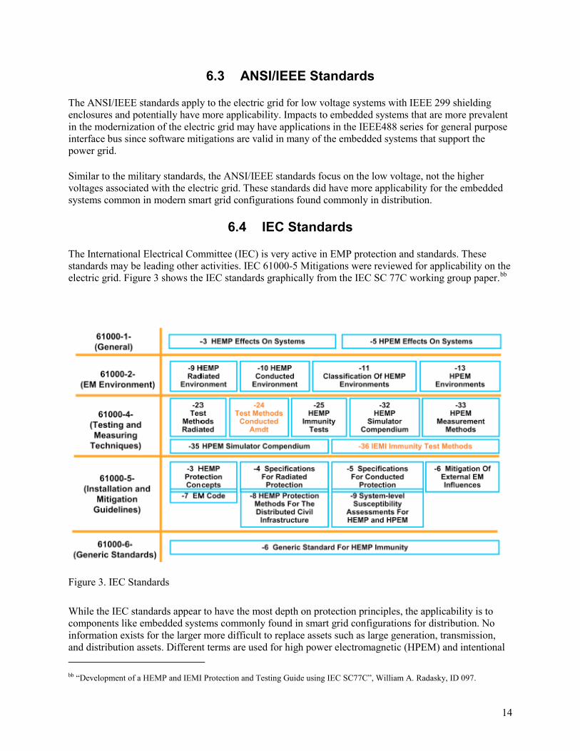
The International Electrical Committee (IEC) is very active in EMP protection and standards. These standards may be leading other activities. IEC 61000-5 Mitigations were reviewed for applicability on the electric grid. Figure 3 shows the IEC standards graphically from the IEC SC 77C working group paper.bb
Figure 3. IEC Standards
While the IEC standards appear to have the most depth on protection principles, the applicability is to components like embedded systems commonly found in smart grid configurations for distribution. No information exists for the larger more difficult to replace assets such as large generation, transmission, and distribution assets. Different terms are used for high power electromagnetic (HPEM) and intentional bb “Development of a HEMP and IEMI Protection and Testing Guide using IEC SC77C”, William A. Radasky, ID 097.
15
electromagnetic interference (IEMI). IEC/TR 61000-5-8 on electromagnetic capability appears to have more information on retrofitting, redundancy in systems, and emergency plans. IEC/TR 61000-5-9 covers the vulnerability assessment requirements which may be a key to defining the problem for utilities.
6.5 ISO Standards
ISO 24673 interference applies to the communications that support the electric grid, and ISO 17334 communications media coating/insulation apply as well.
6.6 UL Standards for Electromagnetic Radiation
UL is a major independent testing organization. UL1449 is the Safety Standards for Low Voltage Surge Protective Devices standard by UL. Equipment built to UL 1449 has a measure of protection against an EMP or EMI. A more complete list of standards is provided in Appendix B.
6.7 Scope of Guidance
Guidance applies to the components, equipment racks and sometimes building/container protections. No guidance with analytical data for design tradeoffs is available for large generators, control centers, transmission or coupling of these subsystems in the electric grid.
6.8 Relevancy to Bulk Electric System
Standards typically lag behind technology but become more relevant for wider adoption. For this reason, some of the mitigations and protections analyzed may not fit perfectly into one standard. An analysis of the potential protection mitigations (with cost and measure available per component) could be used for a tradeoff analysis. Applicability to the whole electric grid as compared to applicability to load center, transmission path or critical component will be installation specific.
7. Protection and Mitigation
7.1 Protection and Mitigation Cost and Effectiveness
7.1.1 Context of Protections
Most mitigations involve hardening of systems to any exposed component (i.e., cabling). These hardening concepts are designed for initial installations and are difficult and expensive to retrofit into existing installations. Hardening involves techniques such as faraday cage shielding, grounding, filters, fast acting current shunt devices, and responsive control systems to manage the effects of possible cascading outages.cc
Protection and mitigation measures for the whole electric grid will need to be procedural-based to be cost effective. Unfortunately, stopping potential impacts from EMP will require retrofitted mitigations, new cc Statement of Dr. William Tedeschi, Senior Scientist, Sandia National Laboratories, U.S. Senate Committee on Energy and Natural Resources May 5, 2011.
16
installations with mitigations and coordination, policies and regulation for the bulk electric system. Operational procedures will have limited effectiveness for E1 protections due to the fast pulse time and lack of warning systems. For an E3 pulse caused by GMD, there is the potential for early warning because of a slower pulse, therefore effective measures could be taken for E3. Utilities may coordinate with their grid interconnects on these procedural mitigation strategies prior to the existence of nationally accepted policy. NERC’s 2012 Special Reliability Assessment Interim Report: Effects of Geomagnetic Disturbances on the Bulk Power System does not set policy or outline procedures. However, at least one individual state (Maine LD-131, Rep. Andrea Boland) proposed legislation for the State’s transmission system to identify mitigation measures and develop options for GMD impacts. These procedural mitigations for GMD are the most likely to be implemented due to the cost for impacts on the bulk electric system, but technical mitigations will be needed for the most vulnerable areas where human procedural intervention will not be timely in the case of E1 or E2 pulse.
For the purposes of this paper, the power grid can prioritize for E1 protections and should be assessed in concert with E2 and E3 protections to avoid unintended consequences. Graded measures for protection and mitigation are needed to enable recovery subsequent to an E1 attack. Full analysis of which facilities are the most critical in restoration and recovery will help refine the below recommended prioritization.
1. Power Generation – This is the “power generation station,” be it fossil fuel, nuclear, hydro, wind, solar, geothermal, or other means; where one form of energy is converted to electrical potential.
For protection, power generation has the highest priority. If the means to generate electrical potential is non-functional, then the rest of the power grid, regardless of how functional, becomes irrelevant. Generation protection is focused on shielding of the facility and all power/communication cables entry/egress shielding.
Similarly, if power generation for a particular site requires external logistic support in order to operate, such as being provided with fossil fuels beyond immediate reserves, then without hardening, those logistical supply lines will become ineffective. As stated previously, analysis information for tradeoff on newer renewable and large (non-nuclear) plant protections is limited.
2. Generation control – This consists of the immediate local control systems, mechanical and/or electrical that are used to functionally control the operation of the power generation. This component has the second highest priority because power generation is essentially dynamic and on demand (i.e. just-in-time).
The generation of power must be controlled to match the demand as electrical power is not a resource that can stored in a practical sense once it is generated. Again, if this functional block of the system is not working, even if the power generation capability is intact, then it does not matter how functional the rest of the system remains. Historically, nuclear generation stations have many protections from EMP. Other generation stations that are more exposed to the outside environment have more difficulty in shielding for EMP. Hydro, fossil, solar, and bio generation are more exposed to the outside. Small and distributed assets, such as solar, commonly have wireless communications back to the power inverters. These connections and devices have not been tested against an EMP. Commonly available consumer electronics and communications are frequently used in generation control. E1 analysis for these systems does not reflect current generation of control (e.g., embedded systems, semiconductors) and communications.
17
3. Transmission – For restoration and recovery, the transmission paths need to be operational when the generation is available. Only one old study focused on transmission assets was found, however it lacked analytical information to support and inform design tradeoffs. Transmission lines, communications for control, towers, substation protections, transformers, switches, relays, and protective equipment are missing analytical data for design decisions. Other analysis on manual relays that are more common in transmission and impact with connectivity to long lines is needed in order to accurately assess transmission vulnerability.
4. Transmission Control – As with generation control, the commonly available modern control and communications systems do not have E1 impact and mitigation analysis readily available. E3 mitigations with transmission control are being researched currently, providing the potential for cost effective mitigations based on sensing harmonics common with GMD. Unfortunately, due to the timing of the fast rise in E1, software mitigations are unlikely. E2 protections (i.e. surge arrestors on the power grid), if positioned properly, may provide some mitigation against E1 pulse effects, as well. Surge arrestors have to be faster acting to protect against E1 as well as E2.dd Design principles for E1 mitigations are needed to guide new installations and upgrades.
5. Power distribution – This consists of the physical means of distributing energy to the consumer, and includes distribution lines, transformers, towers, substations, switches, relays, etc. Existing impact studies are inconsistent on the E1 pulse simulated, direction of lines, or if the test configuration was energized, resulting in inconsistent analysis. Unprotected transformers (without surge arrestors) and assets on lower voltages appear to be more susceptible to E1. The results may be due to the lack of, or undersized, protections since these were not designed to survive an E1 EMP. More modern technologies have been deployed on the distribution systems, since this is the focus for the distribution automation and control with smart grid technologies. These more modern technologies are most likely more susceptible to EMP impacts due to wireless communications and more distributed control.
6. Power distribution control – This consists of control centers and their associated control systems, both mechanical and electrical, that are used to monitor the demands placed on the distribution system and to control the routing and distribution of the available power. More automation and smart grid controls have been installed over the past five years on distribution systems. Again, the common electronic control and modern communication technologies have not been analyzed for E1 impacts. While distribution is not technically part of the bulk electric power grid, a seventh component of the system is the consumer. The consumer typically consists of everything “downstream” of the grid service transformers including the service cables, metering, utility panels, internal wiring, home area networks, smart thermostats, smart appliances, and other end devices.
7.1.2 Cost and Effectiveness
Due to the lack of empirical data, most mitigations for E1 devolve to a discussion of potential costs. The cost of shielding the assets that the utilities consider critical for restart, the cost of critical spares needed for restoration (purchase, storage and maintenance), plus the cost of the actual restoration and recovery.
The cost of shielding varies widely depending on the installation. Some control centers are in facilities designed for reduction of electromagnetic interference (EMI) and EMP with shielding. Surveying those
dd http://www.forbes.com/sites/peterdetwiler/2014/07/31/protecting-the-u-s-against-the-electromagnetic-pulse-threat-a-continued-failure-of-leadership-could-make2-911-look-trivial-someday/4/ Page 3. Accessed June 15, 2015.
18
facilities and analyzing for protections through the range of EMP for limited upgrades is feasible. The cost for shielding long lines (power and communications) and remote facilities not originally designed for EMP protection will be costly. Again, analysis of the facilities to determine those most critical during restoration and recovery will be needed. Those prioritized facilities can be retrofitted for shielding of EMP. Adding EMP design principles to any upgrade or new installation will be cheaper than retrofitting them later. The focus for shielding should be on producing and sharing empirical data that could feed design tools to perform tradeoff analysis of adding EMP mitigation technologies during upgrades and new installations, as compared to retrofitting every asset.
Available published results on the effectiveness of shielding are inconsistent. Again, experimentation and testing with modern grid technologies and shielding for all pulses in EMP are needed.
The cost of spares includes the cost of transformers and maintenance of spares. Transformer spare programs have been researched for sharing programs across utilities. Other research includes recovery transformers enabling quicker installation during restoration. Edison Electric Institute has the Spare Transformer Equipment Program (STEP).ee NERC worked on the Spare Equipment Database which included transformers and the High Impact Low Frequency events report.ff These analyses focus on transmission and generation step up transformers being stored close to areas of need due to difficulty in shipping large infrastructure components and target hundreds of spare transformers. Other media stories indicate the need for up to 2,000 spare transformers. The wide variation of the estimates of the quantity of recommended spare transformers results in a wide cost variance for spare transformers – millions to billions of dollars.gg The Electric Power Research Institute (EPRI) worked on the Recovery Transformer program (RecX) with the Department of Homeland Security-Science and Technology, ABB, INL, and CenterPoint. This project demonstrated the feasibility of designing and deploying modular extra high voltage transformers that can be more readily transported, assembled, tested, and energized.hh
The effectiveness of spares also needs to be considered. Besides the cost of purchasing and maintaining spares, the protection of spares while in storage needs to be considered. Some of the past experimentation was conducted on connected but non-energized systems.
The cost of restoration and recovery are noted in many media articles about EMP. These sources do not distinguish between GMD, EMP weapon, IEMI or HEMP. John P. Holdren (Senior Science and Technology Advisor, Director of the White House Office of Science and Technology Policy) stated in an opinion editorial appearing in the New York Times that the cost for restoration would be $2 Trillion for the first year after a massive GMD event for the United States with a restoration period lasting up to 10 years.ii
The effectiveness of restoration and recovery can be analyzed with national level exercises to understand the larger picture of restoration feasibility. Fuel supply lines (i.e., pipelines and rail) for generation stations and field equipment (i.e., bucket trucks) will be impacted by EMP. In a recent workshop on GMD, investor-owned utility members were interested in partnering for this type of testing on EMP so
ee http://www.eei.org/issuesandpolicy/transmission/Pages/sparetransformers.aspx ff http://www.nerc.com/pa/RAPA/sed/Pages/Spare-Equipment-Database-(SED).aspx gg ”Development of a HEMP and IEMI protection and testing guide using IEC SC77C” William A. Radasky, ID097 hh http://www.dhs.gov/sites/default/files/publications/RecX%20-%20Emergency%20Spare%20Transformer%20Strategy-508.pdf ii http://www.nytimes.com/2011/03/11/opinion/11iht-edholdren11.html?_r=2&adxnnl=1&adxnnlx=1389970815-JWC3EhzrchOAOdxmh1qX+g accessed June 15, 2015.
19
that utilities can understand how to store and maintain restoration equipment and spares that enable recovery.
7.2 Case Study: Protections in Use
7.2.1 Proof of Effectiveness
SEL presented results from testing substation control buildings, relays and intelligent end device (IED) panels to EMP standards focused on military applications. Two military installations where tested with control buildings designed to meet the MIL-STD 188-125A protections for EMP, focused on the points of entry (POE). Using a pulse generator, a shielding effectiveness test of 30-40 dB average attenuation from 10kHz to 10GHz showed that conventional doors, cable entries, and louvers are the main leakage 10-20 dB attenuation. SEL’s test stated that more specialized testing equipment would be needed to prove compliance with the MIL-STD. Recommendations include using fiber optic cables, hardened IEDs, relays, controls and human-machine interface (HMI) computers, and reduction of POE. SEL acknowledged the high cost of manufacturing a control building with an integrated faraday cage.jj No empirical data exist for public sharing with the asset owner utilities.
Older experimentation on vehicles and other military components were identified and surveyed to determine applicability to the electric power grid; however, vehicles (e.g., bucket trucks) will play an important role in recovery and restoration. Specific hardening and hardness maintenance recommendations need to be developed to ensure mission essential vehicles are properly protected.
7.2.2 Protection Strategy Methods and Technologies for the Electric Grid
Protection strategies for the electric grid need to include shared analysis of gaps in understanding EMP impacts and protections. The information needs to include the level of threat to be protected against, the holistic view of support mechanisms, and all energy pulse mitigations to ensure appropriate protection is achieved. Additionally, the information will need to address mitigations that may cause additional vulnerabilities by exacerbating the impacts from other threats. Vetted and shared analysis of existing threat for capability and availability of weapons, impact of pulses on modern grid technologies and communications for control will create the informed strategy for mitigations and aid in the assessment and prioritization for deployment of protections.
Method to Assess: In order to develop an appropriate threat-informed and prioritized EMP protection strategy, the government must assist utilities in identifying methods for conducting vulnerability assessments for critical assets. A very gross estimate follows of what it would cost to perform a vulnerability assessment of all U.S. high priority grid assets, assuming the teams and processes are in place and the information needed to create the process is available (i.e., empirical data).
# operational power plants (U.S. Energy Information Administration): ~7,300 # operational substations (McGee, 2014): ~55000 # critical high voltage substations (McGee, 2014): ~100 # assessment teams available (3-4 members/team + central support staff): 50 Cost of a single plant/site evaluation including travel, report & support: $100,000 Time for single evaluation: 1 week
jj “EMP Effects on Protection and Control Systems”, Copyright SEL 2014, Schweitzer Engineering Laboratories.
20
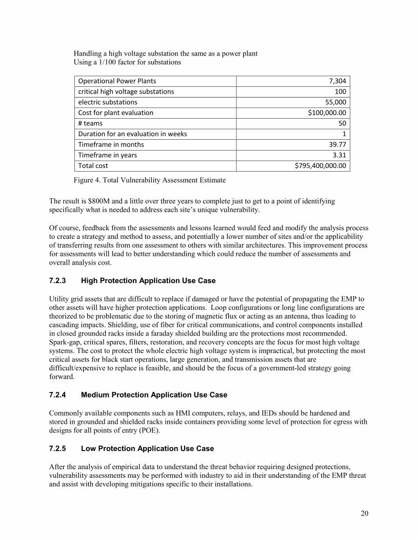
Handling a high voltage substation the same as a power plant Using a 1/100 factor for substations
Operational Power Plants 7,304 critical high voltage substations 100 electric substations 55,000 Cost for plant evaluation $100,000.00 # teams 50 Duration for an evaluation in weeks 1 Timeframe in months 39.77 Timeframe in years 3.31 Total cost $795,400,000.00
Figure 4. Total Vulnerability Assessment Estimate
The result is $800M and a little over three years to complete just to get to a point of identifying specifically what is needed to address each site’s unique vulnerability.
Of course, feedback from the assessments and lessons learned would feed and modify the analysis process to create a strategy and method to assess, and potentially a lower number of sites and/or the applicability of transferring results from one assessment to others with similar architectures. This improvement process for assessments will lead to better understanding which could reduce the number of assessments and overall analysis cost.
7.2.3 High Protection Application Use Case
Utility grid assets that are difficult to replace if damaged or have the potential of propagating the EMP to other assets will have higher protection applications. Loop configurations or long line configurations are theorized to be problematic due to the storing of magnetic flux or acting as an antenna, thus leading to cascading impacts. Shielding, use of fiber for critical communications, and control components installed in closed grounded racks inside a faraday shielded building are the protections most recommended. Spark-gap, critical spares, filters, restoration, and recovery concepts are the focus for most high voltage systems. The cost to protect the whole electric high voltage system is impractical, but protecting the most critical assets for black start operations, large generation, and transmission assets that are difficult/expensive to replace is feasible, and should be the focus of a government-led strategy going forward.
7.2.4 Medium Protection Application Use Case
Commonly available components such as HMI computers, relays, and IEDs should be hardened and stored in grounded and shielded racks inside containers providing some level of protection for egress with designs for all points of entry (POE).
7.2.5 Low Protection Application Use Case
After the analysis of empirical data to understand the threat behavior requiring designed protections, vulnerability assessments may be performed with industry to aid in their understanding of the EMP threat and assist with developing mitigations specific to their installations.
21
Below are listed simplified common steps for a vulnerability assessment process with government provided threat levels and scenario likelihood being key to the overall success.
1. Perform vulnerability assessments – Assemble teams of engineers and specialists capable of performing onsite assessments of a site’s current vulnerability to a possible HEMP/EMP/IEMI attack.
These teams would have general familiarity with EMP mitigation techniques as applied to critical infrastructure, as well as possess specialized knowledge of the type of generation equipment involved and their associated control systems. Other team members would have to be familiar with distribution equipment and its associated operation and control.
The result of a vulnerability assessment should be a report that specifically defines the vulnerabilities for the site and the fixes that would be necessary to mitigate an unexpected EMP event. In addition, for a recommended fix, the report should also contain an expected confidence factor in terms of how reliably a particular protection strategy would mitigate the effects of an EMP event.
The report should also include a list of those items that are most vulnerable or sensitive and will most likely fail should nothing be done. This would be the primary list used to determine what items would be necessary for a recovery from an EMP event, where recovery assets would be located or stored, how to protect these from an EMP, and what type of logistics would be necessary for support of the replacement and how those logistic elements would be protected until needed.
2. Determine the cost of fitting, retrofitting, or rebuilding to implement fixes defined in an assessment report for a particular site’s most critical systems, components and facilities as identified in step 1 above.
3. Prioritize and apply the mitigations defined in an assessment report for a site.
8. Role for Government and Electric Grid Owners/Operators
8.1 Actions and Future Government Role
Standards, past experimentation, and guidance focused on EMP effects to the electric grid are lacking. Given that vendor claims of EMP protections cannot be proven due to lack of EMP experimentation on electric grid assets and no independent verification of test results has been performed. System wide impacts are not known. The government needs to develop and publish validated data for modern grid components, communications (including wireless) and system impacts caused by an E1 attack. These data need to be shared and fed into models that can be used by researchers and industry. Testing of EMP impacts is too risky and costly for private utilities to perform; it is an inherently governmental responsibility.
After basic measurements have been verified with a known model, possessing key characteristics of a modern electric grid, research initiatives can be started to identify novel or better mitigation strategies. Guidance documents and tools should be created to show industry the tradeoff of selecting one mitigation over another, along with the impact to other protections. Ranking the highest to least susceptible to EMP
22
impacts can be used for design decisions or interactions with the equipment manufacturers to configure and install the most hardened options if required by the utility.
Possible Future Actions:
1) Create a research plan to produce and share empirical data with industry and review with other government entities to reduce test duplication.
2) Characterize the EMP threat and identify the most likely assets that industry needs to protect, which covers the range of HEMP/EMP weapons available.
3) Gather experimentation data on: a. Common components (i.e., relays, IEDs, PLCs) b. Communications and shielding (wired copper, fiber optic, and wireless) c. Other mitigations i.e. spark-gap, filters d. Substation racks and control system center protections
4) Incorporate experiment data into models 5) List susceptibility of components (chip sets, cabling, etc.) to be used in design and upgrade
requirements and tradeoff studies by industry 6) Gather experimentation data on grid systems to show propagation and all electric pulse impacts 7) Create policy suggestions based on measured impacts to the electric grid for consideration by
Federal entities and industry 8) Host national level exercises with industry on response from a HEMP/EMP and incorporate
lessons learned into new policy directions or research 9) Calculate an estimate of restoration and recovery from HEMP/EMP and share results with other
policy entities to frame the magnitude of the threat 10) Partner with other government entities that have roles and responsibilities in an event of
HEMP/EMP a. Share information to identify gaps in roles and responsibilities b. Understand policy and law enforcement decisions and jurisdiction if an EMP weapon is
used 11) Conduct workshops with industry and government partners to disseminate data and EMP threat
level and protection findings to gain feedback for further research initiatives and analysis
8.2 Actions and Future Electric Grid Industry Role
Industry will be the key to identifying the most critical assets for protections. While wrapping the whole electric grid in a faraday cage is clearly not practical, key assets will be needed for restoration and reconstitution in the event of a wide spread HEMP/EMP event. These key assets need to be protected from an EMP weapon or HEMP.
1) Identify key assets for restoration from an EMP attack 2) Delineate lines of responsibility between partners for restoration actions between utilities,
equipment suppliers, supply chain issues for materials and labor 3) Exercise possible restoration activities with neighboring utilities to identify gaps in roles and
responsibilities 4) Share results of exercises to improve understanding of the complexities and cost of possible
protections 5) Identify gaps in information back to DOE for further experimentation or inclusion into guidance
documents and tools
23
8.3 Common Areas for Partnerships
The practicality of mitigating assets with operational and maintenance costs needs to be understood and included in the decision for mitigation.
1) Exercise the response to an HEMP and EMP weapon attack with restoration and recovery activities at a large scale
2) Share lessons learned from exercises and testing 3) Share empirical data (as appropriate) from experimentation done by an independent entity (not a
vendor) 4) Provide lessons learned from using government produced guidance from experimental data
9. Conclusion
9.1 Discussion of Gaps
9.1.1 Reference Material
Many reference documents were analyzed for this report. Many of these documents were found to be similar in terms of information detailed. The few novel experimentation results that do exist are partially available to the public, however, the tests are on older technologies or limited EMP power so wouldn’t be of great utility.
9.1.2 Standards and Guidance
Standards and guidance is provided in the military fixed site standards (MIL-STD 188-125) and the IEC standards. Upon reading the limited experimentation reference material, protections for EMP E1 cannot be applied without consideration of the other EMP pulses due to the fact mitigation techniques can cause unintended consequences.
9.1.3 Protection and Mitigation
Almost all known protections and mitigations are focused on the distribution level of the electric grid due to the past military load center hardening focus. Other protections and mitigations for large generator stations and transmission do not reflect the newer threats from EMP weapons and need to be developed and tested.
9.2 Future Direction Discussion
Creating test setups focused on the impact of all EMP pulses on modern grid technologies with mitigations applied will assist industry in understanding which protections are needed, as well as the effectiveness of each. Analyzing experimentation results with new characterized EMP threat data can be used to create informed methods for protections for industry and the government. In partnership, government and industry need to exercise local and large-scale restoration and recovery efforts for a better understanding of the protections needed to maintain the electric grid operations or minimize restoration time.
24
APPENDIX A: Reference Material Summary
International Electrotechnical Commission (1999-07), IEC/TR 61000-5-3 ed1.0, Electromagnetic compatibility (EMC) - Part 5-3: Installation and mitigation guidelines - HEMP protection concepts. Geneva, Switzerland: Author.
International Electrotechnical Commission (1996-08), IEC/TR 61000-5-4 ed1.0, Electromagnetic compatibility (EMC) - Part 5: Installation and mitigation guidelines - Section 4: Immunity to HEMP - Specifications for protective devices against HEMP radiated disturbance. Basic EMC Publication. Geneva, Switzerland: Author.
International Electrotechnical Commission (1996-02), IEC/TR 61000-5-5 ed1.0, Electromagnetic compatibility (EMC) - Part 5: Installation and mitigation guidelines - Section 5: Specification of protective devices for HEMP conducted disturbance. Basic EMC Publication. Geneva, Switzerland: Author.
International Electrotechnical Commission (2009-08), IEC/TR 61000-5-8 ed1.0, Electromagnetic compatibility (EMC) - Part 5-8: Installation and mitigation guidelines - HEMP protection methods for the distributed infrastructure. Geneva, Switzerland: Author.
International Electrotechnical Commission (2009-07), IEC/TR 61000-5-9 ed1.0, Electromagnetic compatibility (EMC) - Part 5-9: Installation and mitigation guidelines - System-level susceptibility assessments for HEMP and HPEM. Geneva, Switzerland: Author.
International Electrotechnical Commission (2003-04), IEC/TR 61000-6-6 ed1.0, Electromagnetic compatibility (EMC) - Part 6-6: Generic standards - HEMP immunity for indoor equipment. Geneva, Switzerland: Author.
Electric Infrastructure Security (EIS) Council (2014-15). EPRO Handbook. Los Angeles, CA: Author.
Research Focused On Improving the Electrical Grid, The Virginia Engineer, vol. LXI, no. 4 (April 2012), pp. 4-6.
Schweitzer Engineering Laboratories (2014) EMP Effects on Protection and Control Systems [PowerPoint Slides]. Schweitzer Engineering Laboratories Inc., Pullman, WA.
Radasky, W., (11 January 2011). HEMP, IEMI and Severe Geomagnetic Storm Effects on Critical Infrastructures [PowerPoint Slides], Metatech Corporation, Goleta, CA.
Koshy , Jason (n.d.). Electromagnetic Mitigation [PowerPoint Slides], Smiths Interconnect – Protection Technology Group, Thousand Oaks, CA.
Hoad, R., & Radasky, W.A (n.d.). High Power Electromagnetic Disturbances to the Smart Grid and the Status of Protection Standards, Metatech Corporation, Goleta, CA.
Foster, J. S., Gjelde, E., Graham, W. R., Hermann, R. J., Kluepfel, H. M., Lawson, R. L., . . . Woodard, J. B. (2004). Report of the Commission to Assess the Threat to the United States from Electromagnetic Pulse (EMP) Attack, Retrieved from http://www.empcommission.org/docs/empc_exec_rpt.pdf
25
Oak Ridge National Laboratory (n.d.) Electromagnetic Pulse: Effects on the U.S. Power Grid, Retrieved from http://www.ornl.gov/sci/ees/etsd/pes/pubs/ferc_Executive_Summary.pdf
Barnes, P. R., (May 4, 1992) Mitigation of Magnetohydrodynamic Electromagnetic Pulse (MHD-EMP) Effects from Commercial Electric Power Systems, Retrieved from http://www.dtic.mil/dtic/tr/fulltext/u2/a249577.pdf
Eder, D. C., Throop, A., Brown, Jr., C. G., Kimbrough, J., Stowell, M. L., White, D. A., . . . Patel P. (March 10, 2009) Mitigation of Electromagnetic Pulse (EMP) Effects from Short-Pulse Lasers and Fusion Neutrons, Retrieved from https://e-reports-ext.llnl.gov/pdf/370813.pdf
Tedeschi, W. (May 5, 2011) Electromagnetic Pulse (EMP) Threats to the U.S. Power Grid, Hearing before the Committee on Energy and Natural Resources, Retrieved from http://www.energy.senate.gov/public/index.cfm/files/serve?File_id=c069ba2b-974c-3d28-38d4-18125d67e023
Infrastructure Security and Energy Restoration Office of Electricity Delivery and Energy Reliability U.S. Department of Energy (June 2012) Large Power Transformers and the U.S. Electric Grid, Retrieved from http://energy.gov/sites/prod/files/2014/04/f15/LPTStudyUpdate-040914.pdf
Garwin, R. (October 2000) Pulsed Power Peer Review Committee Report, Retrieved fromhttp://www.sandia.gov/pulsedpower/newsreleases/reports/GarwinSANDReport.pdf
Savage, E. Gilbert, J. & Radasky, W. (January 2010) The Early-Time (E1) High-Altitude Electromagnetic Pulse (HEMP) and Its Impact on the U.S. Power Grid, Retrieved from http://www.ferc.gov/industries/electric/indus-act/reliability/cybersecurity/ferc_meta-r-320.pdf
Gilbert, J., Kappenman, J., Radasky, W. & Savage, E. (January 2010) The Late-Time (E3) High-Altitude Electromagnetic Pulse (HEMP) and Its Impact on the U.S. Power Grid, Retrieved from http://www.ferc.gov/industries/electric/indus-act/reliability/cybersecurity/ferc_meta-r-321.pdf
Smiths Power – Transtector (n.d.) System Approach to EMP Mitigation, Retrieved from http://www.afcea.org/signal/documents/lea.pdf
Edison Electric Institute (February 2015) Electromagnetic Pulses (EMPs): Myths vs. Facts, Retrieved from http://www.eei.org/issuesandpolicy/cybersecurity/Documents/Electromagnetic%20Pulses%20%28EMPs%29%20-%20Myths%20vs.%20Facts.pdf
Kelly-Detwiler, P. (July 31, 2014) Failure to Protect U.S. Against Electromagnetic Pulse Threat Could Make 9/11 Look Trivial Someday, Retrieved from http://www.forbes.com/sites/peterdetwiler/2014/07/31/protecting-the-u-s-against-the-electromagnetic-pulse-threat-a-continued-failure-of-leadership-could-make-911-look-trivial-someday/
Pry, P.V., Electric Armageddon: Civil-Military Preparedness for an Electromagnetic Pulse Catastrophe, Kindle E-Book, Retrieved from http://www.amazon.com
Nuclear Burst Effects on Electronics. Retrieved from http://www.globalsecurity.org/wmd/library/policy/army/fm/3-3-1_2/Appc.htm

26
United States (9 September 1994 Nuclear Contamination Avoidance, Appendix C, Nuclear Burst Effects on Electronics: Field manual 3-3-1, Washington, DC: Headquarters, Dept. of the Army. Retrieved from http://www.globalsecurity.org/wmd/library/policy/army/fm/3-3-1_2/Appc.htm
THE EMP THREAT: EXAMINING THE CONSEQUENCES: Hearing Before the House of Representatives. 112th Cong. (12 September 2012)

27
APPENDIX B: Reference material Standards and Guidance
Military Standards
MIL-STD-188-125-1 High-Altitude Electromagnetic Pulse (HEMP) Protection for Ground-Based C41 Facilities Performing Critical, Time-Urgent Missions Part 1 Fixed Facility is the most applicable to the whole electric grid due to the tested and verified by military testing and facilities. Military facilities for critical missions have load and power needs more similar to facilities that support the electric grid (i.e., substations, power plants).
Below is the summary for the MIL-STD standards and associated standards for building protections.
MIL-STD 188 is the military standard for various communication systems. MIL-STD 188-125 is the military standard for high altitude electromagnetic pulses or HEMP. MIL-STD-188-125-1 gives the specifications for HEMP hardening of fixed facilities, making fixed communication facilities resistant to EMP bursts. MIL-STD 188-125-2 is the standard for the EMP hardening of transportable systems like command and control systems, communications equipment, sensors and computers.
MIL-STD-202 describes the testing methods and environmental requirements at a component level for electronic components. MIL-STD-202 version G was published in 2002.
MIL-STD 810 gives the Environmental Requirements at a Box Level for electronics, also called the top level assembly. MIL-STD-810 describes the environmental engineering considerations for these units and the laboratory testing they must go through. This includes electromagnetic exposure.
MIL-STD 1541 is the EMC standard for space systems while military standard 1542 gives their grounding requirements. MIL-STD-1310 gives the EMC requirements aboard ships.
MIL-STD 461 sets the EMI or electromagnetic interference requirements for subsystems. MIL-STD 464 describes the EMI electromagnetic interference requirements for systems, the top level unit built from various subsystems.
MIL-STD-1857 describes the military practices for designing, grounding and bonding electromagnetic shielding.
ANSI/IEEE Standards
Most of these standards will apply to the electric grid for low voltages with the IEEE299 shielding enclosures with potential more applicability. Impacts to embedded systems that are more prevalent in the modernization of the electric grid may have applications in the IEEE-488 series for general purpose interface bus since software mitigations are valid in many of the embedded systems that support the power grid.
28
ANSI/IEEE C62.41-1980 – The IEEE Guide for Surge Voltages in Low-Voltage AC Power Circuits applies directly to the electric grid, but only for very low voltages found in distribution residential.
IEEE/ANSI C62.41 is the joint ANSI and IEEE standard for protecting low voltage alternating current power circuits from surges. This standard outlines ways to protect utility power circuits, protect against surge voltages regardless of cause and how to test circuits’ resistance to electromagnetic interference.
ANSI C62.41 was last updated 1991. It is superseded by IEEE STD C62.34, released in 1996 and updated in 2001. Again, this new standard C62.34 “IEEE Standard for Performance of Low-Voltage Surge-Protective Devices (Secondary Arresters)” deals with low voltage.
IEEE 299 is the standard for determining the effectiveness of electromagnetic shielding enclosures like Faraday cages.
IEEE C63.41 gives the standard definition for terms like EMC, EMP and ESD or electrostatic discharge
IEEE-488 general purpose interface bus (GPIB)
IEEE-Std-488.1 – Standard Digital Interface for Programmable Instrumentation – superseded by 488.2-1992
IEC/TR 61000-5-3 ed1.0
Electromagnetic compatibility (EMC) - Part 5-3: Installation and mitigation guidelines - HEMP protection concepts
This document specifically goes into depth on protection principals, protection in layers, installation guidelines, protection devices, etc. however it is a generalized approach with no specifics toward power grid installations, though different aspects can be applied to components of a power grid or installations.
IEC/TR 61000-5-4 ed1.0
Electromagnetic compatibility (EMC) - Part 5: Installation and mitigation guidelines - Section 4: Immunity to HEMP - Specifications for protective devices against HEMP radiated disturbance. Basic EMC Publication
This document is primarily concerned with protection devices, materials and installation techniques that address radiated disturbance such as barrier materials, shielding on cables, gasketing materials, etc.
IEC/TR 61000-5-5 ed1.0
Electromagnetic compatibility (EMC) - Part 5: Installation and mitigation guidelines - Section 5: Specification of protective devices for HEMP conducted disturbance. Basic EMC Publication
29
This document primarily provides a list of devices and circuits with specifications and characteristics that can be used for the mitigation of conducted disturbance such as Voltage breakdown devices, Voltage limiting devices, isolation devices, bandwidth limiting devices, etc.
IEC/TR 61000-5-8 ed1.0
Electromagnetic compatibility (EMC) - Part 5-8: Installation and mitigation guidelines - HEMP protection methods for the distributed infrastructure
This document is the most relevant in terms of addressing power grids and infrastructure; however it is approaching the topic from a relatively high level describing protection strategies using standards for new equipment, retrofitting, redundancy in systems, emergency plans, and restoration plans.
IEC/TR 61000-5-9 ed1.0
Electromagnetic compatibility (EMC) - Part 5-9: Installation and mitigation guidelines - System-level susceptibility assessments for HEMP and HPEM
This document primarily focuses on how to perform susceptibility assessments for back-door coupling on system level installations in general and is not specific in terms of the power grid though there is some applicability. It is a bottom up phased approach characterizing subsystems, equipment and placement topology, then analysis, and testing. There is a lot on characterization, but not much on mitigation.
IEC/TR 61000-6-6 ed1.0
Electromagnetic compatibility (EMC) - Part 6-6: Generic standards - HEMP immunity for indoor equipment
This document primarily provides definitions and criteria against which devices can be tested to claim a level of immunity against HEMP. It defines “Protection Concepts” which are environments with a described level of shielding or protection within which the devices are contained, and it defines immunity tests to be performed against various “ports” that a device may contain through which an EMP can affect the device.
ISO Standards
ISO 24673interference will apply for the communications that support the electric grid, and ISO 17334 communications coating will apply as well.
ISO 24673 is the standard for reporting the results of electromagnetic interference testing.
ISO 21609 gives the guidelines for installing radio frequency transmitting equipment like CB radios in vehicles in a way that does not interfere with other systems in the car.
30
ISO 17334 is the standard for metallic coatings like nickel over copper wiring to provide non-organic EMP protection. Plastic sheathes around wiring also provides a measure of electromagnetic protection.
UL Standards for Electromagnetic Radiation
Underwriters Laboratories or UL is a major independent testing organization. UL1449 is the Safety Standards for Low Voltage Surge Protective Devices standard by UL. Equipment built to UL 1449 has a measure of protection against an EMP or EMI.

31
APPENDIX C: Test and Experimentation Summary
Below are summaries of tests and experimentation done in the past related to electric power grid and HEMP from research of past materials. As expected, little information exists for modern testing with the exception of testing done by the vendor Schweitzer Engineering Laboratories (SEL). Other tests are decades old, lacking instrumentation, and modern grid technologies. This information is provided to show what is known in testing and experimentation in the unclassified sources.
SEL presented results from testing substation control houses, relays and intelligent end device (IED) panels to EMP standards focused on the military applications. Two military installations where tested with control housing to meet the MIL-STD 188-125A protections for EMP again focused on the points of entry (POE). Using a pulse generator, shielding effectiveness test of 30-40 dB average attenuation from 10kHz to 10GHz showed that conventional doors, cable entries and louvers are the main leakage 10-20 dB attenuation. SEL’s test stated that more specialized testing equipment would be needed to prove compliance with the MIL-STD. Recommendations include using fiber, hardened IEDs, relays, controls and human-machine interface (HMI) computers, reduction of POE and SEL acknowledge the high cost of manufacturing a control building with integrated faraday cage.kk No empirical data exists for public sharing with the asset owner utilities.
U.S. atmospheric test programs in 1962 Starfish Prime test detonation over the Johnston Atoll in the Pacific Ocean and some electronic and electrical systems in the Hawaiian Islands over 1400 kilometers away casing failure of street lighting, tripping of circuit breakers and damage to telecommunications relay facility. Soviet atmospheric testing during the same year impacted South Central Asia causing damage to overhead and underground buried cables, surge arrestor burnout spark-gap breakdown, blown fuses and power supply breakdown. The antenna affect caused buried cable damage at 600 kilometers.ll Radio disruptions over 30 minutes due to ionosphere interference and other GMD related impacts were noted.mm Unfortunately during the 1962 detonations, systems were not instrumented for data collection of empirical data, so these impacts are based on observations that are over 50 years old.
A 1998 summary of testing on 110kV lines energized and non-energized resulting in sparkover to flashovers at 350kV pulse with some broken porcelain insulators. Other protection type equipment (valve/tube dischargers, shield gaps and non-linear resisters) proved to be not sufficient for fast-acting HEMP effects. Low voltage windings of high voltage transformers broke down at 400kV pulse. Finally mobile diesel power stations were vulnerable to HEMP due to supply power cables.nn
Another power line study was done in 1998 in Italy focusing on the angle of the power line resulting in large differences between measured and simulator results. Train rail lines acting as an antenna near a power line were studies in 1975. oo
kk “EMP Effects on Protection and Control Systems”, Copyright SEL 2014, Schweitzer Engineering Laboratories. ll “Report of the Commission to Assess the Threat to the United States from Electromagnetic Pulse (EMP) Attack”, Volume 1: Executive Report 2004. Dr. John S. Foster, Jr. et al., page 4. mm Electromagnetic compatibility (EMC), Part 1-3 General – The effects of high altitude EMP (HEMP) on civil equipment and systems. TR 61000-1-3 pages 11-14. nn Electromagnetic compatibility (EMC), Part 1-3 General – The effects of high altitude EMP (HEMP) on civil equipment and systems. TR 61000-1-3 page 36. oo Electromagnetic compatibility (EMC), Part 1-3 General – The effects of high altitude EMP (HEMP) on civil equipment and systems. TR 61000-1-3 pages 28-32.
32
In 1998, distribution transformers were tested with a HEMP simulator with unprotected transformers failing between 250 kV and 300kV. The failure mode was internal flashover/puncture between higher-voltage winding and low-voltage winding. Placement of the surge arrester and lightning protection needed to be on the transformer tank to aid in the protection of the HEMP transient. Nineteen transformers standard distribution <25kVA were tested with 1/3 of these failing.pp
The impact of E1 on system voltage stress and flashover effects resulting in load and generation loss and/or damage were the results of the 1991 study by Oak Ridge National Laboratory. Based on limited testing and calculations the Flashover is the voltage magnitude of a defined surge, is more likely at lower voltages (i.e. < 69kV). Other factors such as insulator strength were limited and assumed conservative. Flashovers do not directly impact power system security, but he resultant loss of load would cause an imbalance. This study excluded the control circuits and complex systems such as control environments. The final part of this study focused on multiple HEMP blasts predicting total generation loss.qq
Consumer Electronics and Communications
Additional studies on EMP impact to consumer electronics in the late 1980’s showed failures and critical upsets for most devices ranging from mobile radios, computers and cellular phones. In the 1974, other EMP tests were done on communications radios showed citizen band ‘walkie talkies’ and land mobile radios (VHF low and high band) malfunctions and half had damaged components. Unfortunately, these test components and communication impacts were on older components without the benefit of instrumentation to understand the level at which point disruption or failures occurred. There is limited information on any shielding used for these components or communication lines as well.rr In a National Communications Systems report from 1988, not all fiber connections are protected from HEMP. Inconclusive results based on power converters for line repeaters and central office connections may impact the usability of fiber communications during HEMP.ss
pp Electromagnetic compatibility (EMC), Part 1-3 General – The effects of high altitude EMP (HEMP) on civil equipment and systems. TR 61000-1-3 pages 36-44. qq “Impacts of a Nominal Nuclear Electromagnetic Pulse on Electric Power Systems” Phase III Final Report June 18, 1991 91-02235 rr Electromagnetic compatibility (EMC), Part 1-3 General – The effects of high altitude EMP (HEMP) on civil equipment and systems. TR 61000-1-3 pages 21-27. ss National Communication Systems Technical Information Bulletin 88-3 “The Effects of High-Altitude Electromagnetic Pulse (HEMP) on Telecommunications Assets”, June 1988.