strata cix40 install r1 ~ r3 hardware -...
TRANSCRIPT
TOSHIBA Telecommunication Systems Division
Strata CIX40R5.2 Software - R1 ~ R3 Hardware
Installation and Maintenance ManualTitle Page
®
May 2010
Publication Information
Toshiba America Information Systems, Inc.
Telecommunication Systems Division
Publication InformationToshiba America Information Systems, Inc., Telecommunication Systems Division, reserves the right, without prior notice, to revise this information publication for any reason, including, but not limited to, utilization of new advances in the state of technical arts or to simply change the design of this document.
Further, Toshiba America Information Systems, Inc., Telecommunication Systems Division, also reserves the right, without prior notice, to make such changes in equipment design or components as engineering or manufacturing methods may warrant.
CIX-IM-CIX40-VC-E
Version C4, May, 2010
Our mission to publish accurate, complete and user accessible documentation. At the time of printing the information in this document was as accurate and current as was reasonably possible. However, in the time required to print and distribute this manual additions, corrections or other changes may have been made. To view the latest version of this or other documents please refer to the Toshiba FYI web site.
Toshiba America Information Systems shall not be liable for any commercial losses, loss of revenues or profits, loss of goodwill, inconvenience, or exemplary, special, incidental, indirect or consequential damages whatsoever, or claims of third parties, regardless of the form of any claim that may result from the use of this document.
THE SPECIFICATIONS AND INFORMATION PROVIDED HEREIN ARE FOR INFORMATIONAL PURPOSES ONLY AND ARE NOT A WARRANTY OF ACTUAL PERFORMANCE, WHETHER EXPRESSED OR IMPLIED. THE SPECIFICATIONS AND INFORMATION ARE SUBJECT TO CHANGE WITHOUT NOTICE. ACTUAL PERFORMANCE MAY VARY BASED ON INDIVIDUAL CONFIGURATIONS, USE OF COLLATERAL EQUIPMENT, OR OTHER FACTORS.
© Copyright 2006 ~ 2010This document is copyrighted by Toshiba America Information Systems, Inc. with all rights reserved. Under the copyright laws, this document cannot be reproduced in any form or by any means—graphic, electronic, or mechanical, including recording, taping, photocopying, without prior written permission of Toshiba. No patent liability is assumed, however, with respect to the use of the information contained herein.
TrademarksToshiba, Strata, SmartMedia, SD (Secure Digital), Toshiba, and CIX are registered trademarks of Toshiba Corporation. Stratagy, eManager, My Phone Manager and Info Manager are registered trademarks of Toshiba America Information Systems, Inc. Windows and Microsoft are registered trademarks of Microsoft.Trademarks, registered trademarks, and service marks are the property of their respective owners.
Strata CIX40 General End User InformationThe Strata CIX40 IP Business Communication System is registered in accordance with the provisions of Part 68 of the Federal Communications Commission’s Rules and Regulations.
FCC RequirementsMeans of Connection: The Federal Communications Commission (FCC) has established rules which permit the Strata CIX system to be connected directly to the telephone network. Connection points are provided by the telephone company—connections for this type of customer-provided equipment will not be provided on coin lines. Connections to party lines are subject to state tariffs.
Incidence of Harm: If the system is malfunctioning, it may also be disrupting the telephone network. The system should be disconnected until the problem can be determined and repaired. If this is not done, the telephone company may temporarily disconnect service. If possible, they will notify you in advance, but, if advance notice is not practical, you will be notified as soon as possible. You will be informed of your right to file a complaint with the FCC.
Service or Repair: For service or repair, contact your local Toshiba telecommunications distributor. To obtain the nearest Toshiba telecommunications distributor in your area, log onto www.toshiba.com/taistsd/pages/support_dealerlocator.html or call (800) 222-5805 and ask for a Toshiba Telecom Dealer.
Telephone Network Compatibility: The telephone company may make changes in its facilities, equipment, operations, and procedures. If such changes affect the compatibility or use of the Strata CIX100, CIX200 or CIX670 system, the telephone company will notify you in advance to give you an opportunity to maintain uninterrupted service.
Notification of Telephone Company: Before connecting a Strata CIX system to the telephone network, the telephone company may request the following:
1.Your telephone number.2.FCC and ACTA registration
• Strata CIX100, CIX200 or CIX670 may be configured as a Key, Hybrid or PBX telephone system. The appropriate configuration for your system is dependent upon your operation of the system.
• If the operation of your system is only manual selection of outgoing lines, it may be registered as a Key telephone system.
• If your operation requires automatic selection of outgoing lines, such as dial access, Least Cost Routing, Pooled Line Buttons, etc., the system must be registered as a Hybrid telephone system. In addition to the above, certain features (tie Lines, Off-premises Stations, etc.) may also require Hybrid telephone system registration in some areas.
• If you are unsure of your type of operation and/or the appropriate FCC registration number, contact your local Toshiba telecommunications distributor for assistance.
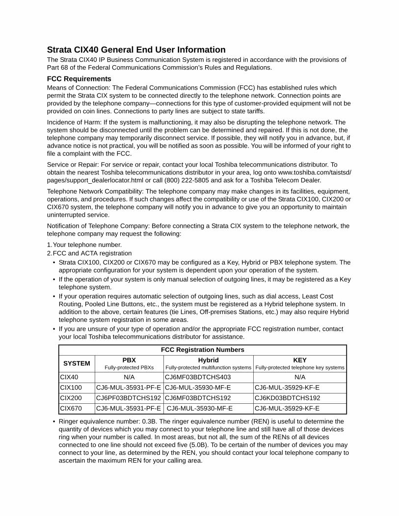
• Ringer equivalence number: 0.3B. The ringer equivalence number (REN) is useful to determine the quantity of devices which you may connect to your telephone line and still have all of those devices ring when your number is called. In most areas, but not all, the sum of the RENs of all devices connected to one line should not exceed five (5.0B). To be certain of the number of devices you may connect to your line, as determined by the REN, you should contact your local telephone company to ascertain the maximum REN for your calling area.
FCC Registration Numbers
SYSTEM PBXFully-protected PBXs
HybridFully-protected multifunction systems
KEYFully-protected telephone key systems
CIX40 N/A CJ6MF03BDTCHS403 N/A
CIX100 CJ6-MUL-35931-PF-E CJ6-MUL-35930-MF-E CJ6-MUL-35929-KF-E
CIX200 CJ6PF03BDTCHS192 CJ6MF03BDTCHS192 CJ6KD03BDTCHS192
CIX670 CJ6-MUL-35931-PF-E CJ6-MUL-35930-MF-E CJ6-MUL-35929-KF-E
3.Network connection information USOC jack required: RJ11/14C, RJ21/2E/2F/2G/2HX/RJ49C (see Network Requirements in this document). Items 2, 3 and 4 are also indicated on the equipment label.
4.Authorized Network Parts: 02LS2/GS2, 02RV2-T/O, OL13C/B, T11/12/31/32M, 04DU9-BN/DN/1SN, 02IS5, 04DU9-BN/DN/1SN1ZN
Radio Frequency InterferenceWarning: This equipment generates, uses, and can radiate radio frequency energy and if not installed and used in accordance with the manufacturer’s instruction manual, may cause interference to radio communications. It has been tested and found to comply with the limits for a Class A computing device pursuant to Subpart J of Part 15 of FCC Rules, which are designed to provide reasonable protection against such interference when operated in a commercial environment. Operation of this equipment in a residential area is likely to cause interference, in which case, the user, at his/her own expense, will be required to take whatever measures may be required to correct the interference.
Underwriters LaboratoryThis system is listed with Underwriters Laboratory (UL). Secondary protection is required, on any wiring from any telephone that exits the building or is subject to lightning or other electrical surges, and on DID, OPS, and Tie lines. (Additional information is provided in this manual.)
Important Notice — Music-On-HoldIn accordance with U.S. Copyright Law, a license may be required from the American Society of Composers, Authors and Publishers, or other similar organization, if radio or TV broadcasts are transmitted through the music-on-hold feature of this telecommunication system. Toshiba America Information Systems, Inc., strongly recommends not using radio or television broadcasts and hereby disclaims any liability arising out of the failure to obtain such a license.
CP01, Issue 8, Part I Section 14.1Notice: The Industry Canada label identifies certified equipment. This certification means that the equipment meets certain telecommunications network protective, operational and safety requirements as prescribed in the appropriate Terminal Equipment Technical Requirements document(s). The Department does not guarantee the Equipment will operate to the user’s satisfaction.
Before installing this equipment, users should ensure that it is permissible to be connected to the facilities of the local telecommunications company. The equipment must also be installed using an acceptable method of connection. The customer should be aware that compliance with the above conditions may not prevent degradation of service in some situations.
Repairs to certified equipment should be coordinated by a representative designated by the supplier. Any repairs or alterations made by the user to this equipment, or equipment malfunctions, may give the telecommunications company cause to request the user to disconnect the equipment.Users should ensure for their own protection that the electrical ground connections of the power utility, telephone lines and internal metallic water pipe system, if present, are connected together. This precaution may be particularly important in rural areas.
CAUTION! Users should not attempt to make such connections themselves, but should contact the appropriate electric inspection authority, or electrician, as appropriate.
CP01, Issue 8, Part I Section 14.2Ringer Equivalence Notice: The Ringer Equivalence Number (REN) assigned to each terminal device provides an indication of the maximum number of terminals allowed to be connected to a telephone interface. The terminal on an interface may consist of any combination of devices subject only to the requirement that the sum of the Ringer Equivalence Numbers of all the Devices does not exceed 5.
Hearing Aid Compatibility Notice: The FCC has established rules that require all installed business telephones be hearing aid compatible. This rule applies to all telephones regardless of the date of manufacture or installation. There are severe financial penalties which may be levied on the end-user for non-compliance.
49L7I.T.E

TOSHIBA AMERICA INFORMATION SYSTEMS, INC. (“TAIS”)Telecommunication Systems Division License Agreement
IMPORTANT: THIS LICENSE AGREEMENT (“AGREEMENT”) IS A LEGAL AGREEMENT BETWEEN YOU (“YOU”) AND TAIS. CAREFULLY READ THIS LICENSE AGREEMENT. USE OF ANY SOFTWARE OR ANY RELATED INFORMATION (COLLECTIVELY, “SOFTWARE”) INSTALLED ON OR SHIPPED WITH A TAIS DIGITAL SOLUTIONS PRODUCT OR OTHERWISE MADE AVAILABLE TO YOU BY TAIS IN WHATEVER FORM OR MEDIA, WILL CONSTITUTE YOUR ACCEPTANCE OF THESE TERMS, UNLESS SEPARATE TERMS ARE PROVIDED BY THE SOFTWARE SUPPLIER. IF YOU DO NOT AGREE WITH THE TERMS OF THIS LICENSE AGREEMENT, DO NOT INSTALL, COPY OR USE THE SOFTWARE AND PROMPTLY RETURN IT TO THE LOCATION FROM WHICH YOU OBTAINED IT IN ACCORDANCE WITH APPLICABLE RETURN POLICIES. EXCEPT AS OTHERWISE AUTHORIZED IN WRITING BY TAIS, THIS SOFTWARE IS LICENSED FOR DISTRIBUTION THROUGH TAIS AUTHORIZED CHANNELS ONLY TO END-USERS PURSUANT TO THIS LICENSE AGREEMENT.
1. License Grant. The Software is not sold; it is licensed upon payment of applicable charges. TAIS grants to you a personal, non-transferable and non-exclusive right to use the copy of the Software provided under this License Agreement. You agree you will not copy the Software except as necessary to use it on one TAIS system at a time at one location. Modifying, translating, renting, copying, distributing, printing, sublicensing, transferring or assigning all or part of the Software, or any rights granted hereunder, to any other persons and removing any proprietary notices, labels or marks from the Software is strictly prohibited except as permitted by applicable law; you agree violation of such restrictions will cause irreparable harm to TAIS and provide grounds for injunctive relief, without notice, against you or any other person in possession of the Software. You and any other person whose possession of the software violates this License Agreement shall promptly surrender possession of the Software to TAIS, upon demand. Furthermore, you hereby agree not to create derivative works based on the Software. TAIS reserves the right to terminate this license and to immediately repossess the software in the event that you or any other person violates this License Agreement. Execution of the Software for any additional capabilities require a valid run-time license.
2. Intellectual Property. You acknowledge that no title to the intellectual property in the Software is transferred to you. You further acknowledge that title and full ownership rights to the Software will remain the exclusive property of TAIS and/or its suppliers, and you will not acquire any rights to the Software, except the license expressly set forth above. You will not remove or change any proprietary notices contained in or on the Software. The Software is protected under US patent, copyright, trade secret, and/or other proprietary laws, as well as international treaties. Any transfer, use, or copying of the software in violation of the License Agreement constitutes copyright infringement. You are hereby on notice that any transfer, use, or copying of the Software in violation of this License Agreement constitutes a willful infringement of copyright.
3. No Reverse Engineering. You agree that you will not attempt, and if you employ employees or engage contractors, you will use your best efforts to prevent your employees and contractors from attempting to reverse compile, reverse engineer, modify, translate or disassemble the Software in whole or in part. Any failure to comply with the above or any other terms and conditions contained herein will result in the automatic termination of this license and the reversion of the rights granted hereunder back to TAIS.
4. Limited Warranty. THE SOFTWARE IS PROVIDED “AS IS” WITHOUT WARRANTY OF ANY KIND. TO THE MAXIMUM EXTENT PERMITTED BY APPLICABLE LAW, TAIS AND ITS SUPPLIERS DISCLAIM ALL WARRANTIES WITH REGARD TO THE SOFTWARE, EITHER EXPRESS OR IMPLIED, INCLUDING, BUT NOT LIMITED TO, THE WARRANTY OF NON-INFRINGEMENT OF THIRD PARTY RIGHTS, THE WARRANTY OF YEAR 2000 COMPLIANCE, AND THE IMPLIED WARRANTIES OF MERCHANTABILITY AND FITNESS FOR A PARTICULAR PURPOSE. THE ENTIRE RISK AS TO THE QUALITY AND PERFORMANCE OF THE SOFTWARE IS WITH YOU. NEITHER TAIS NOR ITS SUPPLIERS WARRANT THAT THE FUNCTIONS CONTAINED IN THE SOFTWARE WILL MEET YOUR REQUIREMENTS OR THAT THE OPERATION OF THE SOFTWARE WILL BE UNINTERRUPTED OR ERROR-FREE. HOWEVER, TAIS WARRANTS THAT ANY MEDIA ON WHICH THE SOFTWARE IS FURNISHED IS FREE FROM DEFECTS IN MATERIAL AND WORKMANSHIP UNDER NORMAL USE FOR A PERIOD OF NINETY (90) DAYS FROM THE DATE OF DELIVERY TO YOU.
5. Limitation Of Liability. TAIS’ ENTIRE LIABILITY AND YOUR SOLE AND EXCLUSIVE REMEDY UNDER THIS LICENSE AGREEMENT SHALL BE AT TAIS’ OPTION REPLACEMENT OF THE MEDIA OR REFUND OF THE PRICE PAID. TO THE MAXIMUM EXTENT PERMITTED BY APPLICABLE LAW, IN NO EVENT SHALL TAIS OR ITS SUPPLIERS BE LIABLE TO YOU FOR ANY CONSEQUENTIAL, SPECIAL, INCIDENTAL OR INDIRECT DAMAGES FOR PERSONAL INJURY, LOSS OF BUSINESS PROFITS, BUSINESS INTERRUPTION, LOSS OF BUSINESS INFORMATION/DATA, OR ANY OTHER PECUNIARY LOSS OF ANY KIND ARISING OUT OF THE USE OR INABILITY TO USE THE SOFTWARE, EVEN IF TAIS OR ITS SUPPLIER HAS BEEN ADVISED OF THE POSSIBILITY OF SUCH DAMAGES. IN NO EVENT SHALL TAIS OR ITS SUPPLIERS BE LIABLE FOR ANY CLAIM BY A THIRD PARTY.
6. State/Jurisdiction Laws. SOME STATES/JURISDICTIONS DO NOT ALLOW THE EXCLUSION OF IMPLIED WARRANTIES OR LIMITATIONS ON HOW LONG AN IMPLIED WARRANTY MAY LAST, OR THE EXCLUSION OR LIMITATION OF INCIDENTAL OR CONSEQUENTIAL DAMAGES, SO SUCH LIMITATIONS OR EXCLUSIONS MAY NOT APPLY TO YOU. THIS LIMITED WARRANTY GIVES YOU SPECIFIC RIGHTS AND YOU MAY ALSO HAVE OTHER RIGHTS WHICH VARY FROM STATE/JURISDICTION TO STATE/JURISDICTION.
7. Export Laws. This License Agreement involves products and/or technical data that may be controlled under the United States Export Administration Regulations and may be subject to the approval of the United States Department of Commerce prior to export. Any export, directly or indirectly, in contravention of the United States Export Administration Regulations, or any other applicable law, regulation or order, is prohibited.
8. Governing Law. This License Agreement will be governed by the laws of the State of California, United States of America, excluding its conflict of law provisions.
9. United States Government Restricted Rights. The Software is provided with Restricted Rights. The Software and other materials provided hereunder constitute Commercial Computer Software and Software Documentation and Technical Data related to Commercial Items. Consistent with F.A.R. 12.211 and 12.212 they are licensed to the U.S. Government under, and the U.S. Government’s rights therein are restricted pursuant to, the vendor’s commercial license.
10. Severability. If any provision of this License Agreement shall be held to be invalid, illegal or unenforceable, the validity, legality and enforceability of the remaining provisions hereof shall not in any way be affected or impaired.
11. No Waiver. No waiver of any breach of any provision of this License Agreement shall constitute a waiver of any prior, concurrent or subsequent breach of the same or any other provisions hereof, and no waiver shall be effective unless made in writing and signed by an authorized representative of the waiving party.
12. Supplier Software. The Software may include certain software provided by TAIS suppliers. In such event, you agree that such supplier may be designated by TAIS as a third party beneficiary of TAIS with rights to enforce the Agreement with respect to supplier’s software.
YOU ACKNOWLEDGE THAT YOU HAVE READ THIS LICENSE AGREEMENT AND THAT YOU UNDERSTAND ITS PROVISIONS. YOU AGREE TO BE BOUND BY ITS TERMS AND CONDITIONS. YOU FURTHER AGREE THAT THIS LICENSE AGREEMENT CONTAINS THE COMPLETE AND EXCLUSIVE AGREEMENT BETWEEN YOU AND TAIS AND SUPERSEDES ANY PROPOSAL OR PRIOR AGREEMENT, ORAL OR WRITTEN, OR ANY OTHER COMMUNICATION RELATING TO THE SUBJECT MATTER OF THIS LICENSE AGREEMENT.
Toshiba America Information Systems, Inc.Telecommunication Systems Division9740 Irvine BoulevardIrvine, California 92618-1697 United States of America
DSD 020905
5932

T
Toshiba America Information Systems, Inc.Telecommunication Systems Division
End-User Limited Warranty
Toshiba America Information Systems, Inc., (“TAIS”) warrants that this telephone equipment manufactured by Toshiba (except for fuses, lamps, and other consumables) will, upon delivery by TAIS or an authorized TAIS dealer to a retail customer in new condition, be free from defects in material and workmanship for twenty-four (24) months after delivery, except as otherwise provided by TAIS in the TAIS warranty accompanying the products or posted on TAIS’s website. Products which are not manufactured by Toshiba but are purchased from Toshiba, will be subject to the warranty provisions provided by the equipment manufacturer, unless TAIS notifies the end-user of any additional warranty provisions in writing.
This warranty is void (a) if the equipment is used under other than normal use and maintenance conditions, (b) if the equipment is modified or altered, unless the modification or alteration is expressly authorized by TAIS, (c) if the equipment is subject to abuse, neglect, lightning, electrical fault, or accident, (d) if the equipment is repaired by someone other than TAIS or an authorized TAIS dealer, (e) if the equipment’s serial number is defaced or miss-ing, or (f) if the equipment is installed or used in combination or in assembly with products not supplied by TAIS and which are not compatible or are of inferior quality, design, or performance.
The sole obligation of TAIS or Toshiba Corporation under this warranty, or under any other legal obligation with respect to the equipment, is the repair or replacement of such defective or missing parts as are causing the malfunc-tion by TAIS or its authorized dealer with new or refurbished parts (at their option). If TAIS or one of its autho-rized dealers does not replace or repair such parts, the retail customer’s sole remedy will be a refund of the price charged by TAIS to its dealers for such parts as are proven to be defective, and which are returned to TAIS through one of its authorized dealers within the warranty period and no later than thirty (30) days after such malfunction, whichever first occurs.
Under no circumstances will the retail customer or any user or dealer or other person be entitled to any direct, special, indirect, consequential, or exemplary damages, for breach of contract, tort, or otherwise. Under no circum-stances will any such person be entitled to any sum greater than the purchase price paid for the item of equipment that is malfunctioning.
To obtain service under this warranty, the retail customer must bring the malfunction of the machine to the atten-tion of one of TAIS’ authorized dealers within the applicable warranty period and no later than thirty (30) days after such malfunction, whichever first occurs. Failure to bring the malfunction to the attention of an authorized TAIS dealer within the prescribed time results in the customer being not entitled to warranty service.
THERE ARE NO OTHER WARRANTIES FROM EITHER TOSHIBA AMERICA INFORMATION SYSTEMS, INC., OR TOSHIBA CORPORATION WHICH EXTEND BEYOND THE FACE OF THIS WARRANTY. ALL OTHER WARRANTIES, EXPRESS OR IMPLIED, INCLUDING THE WARRANTIES OF MERCHANTABILITY, FITNESS FOR A PARTICULAR PURPOSE, AND FITNESS FOR USE, ARE EXCLUDED.
No TAIS dealer and no person other than an officer of TAIS may extend or modify this warranty. No such modifi-cation or extension is effective unless it is in writing and signed by the Vice President and General Manager, Tele-communication Systems Division.

WARRANTIES FOR NON-TOSHIBA BRANDED THIRD PARTY PRODUCTS
A valuable element of Toshiba’s product strategy is to offer our customers a complete product portfolio. To provide this value to our customers at the most optimal prices, we offer both Toshiba-branded and third-party manufactured products that support our Toshiba Strata CIX product portfolio. Similar to other resellers of software, hardware and peripherals, these third-party manufactured products carry warranties independent of our Toshiba limited warranty provided with our Toshiba-branded products. Customers should note that third-party manufacturer warranties vary from product to product and are covered by the warranties provided through the original manufacturer and passed on intact to the purchaser by Toshiba. Customers should consult their product documentation for third-party warranty information specific to third-party products. More information may also be available in some cases from the manufacturer’s public website.
While Toshiba offers a wide selection of software, hardware and peripheral products, we do not specifically test or guarantee that the third-party products we offer work under every configuration with any or all of the various models of the Toshiba Strata CIX. Toshiba does not endorse, warrant nor assume any liability in connection with such third party products or services. If you have questions about compatibility, we recommend and encourage you to contact the third-party software, hardware and peripheral product manufacturer directly.

This page is intentionally left blank.
Strata CIX40 R3 Installation & Maintenance 05/10 i
Contents
Chapter 1 – CIX40 InstallationCIX40 Introduction .............................................................................................................................1-1CIX40 System Cabinet Versions ........................................................................................................1-2
CIX40 Release 2 and Release 3 Cabinet System Capacities .....................................................1-2CIX40 Release 1 Cabinet System Capacities .............................................................................1-3
CIX40 R5.20 Software .......................................................................................................................1-4CIX40 Software Backup and Restore Capability .........................................................................1-4
CIX40 System Licenses .....................................................................................................................1-4CIX40 Cabinet Specifications .............................................................................................................1-5Safety Registration .............................................................................................................................1-5CIX40 CHSU40A3 FCC/ACTA Registration Number .........................................................................1-5Telephone Compatibility .....................................................................................................................1-5Inspection ..........................................................................................................................................1-7Packaging and Storage ......................................................................................................................1-7Site Requirements ..............................................................................................................................1-8
Input Power .................................................................................................................................1-8Clearance and Location ...............................................................................................................1-8
AC Power and Grounding Requirements .........................................................................................1-10Ground Wire Connection ...........................................................................................................1-11Ground Test ...............................................................................................................................1-11
Installing the CIX40 Cabinet .............................................................................................................1-12CIX40 Cabinet Slots .........................................................................................................................1-15Printed Circuit Boards ......................................................................................................................1-17CIX40 Processor ..............................................................................................................................1-18
GCTU2 Processor Interfaces ....................................................................................................1-19IP Interface Cards ............................................................................................................................1-21GCOCIH ...........................................................................................................................................1-22GCDU2 (DKT and Loop Start Interface) ..........................................................................................1-22GVPH ...............................................................................................................................................1-23GSTU1 .............................................................................................................................................1-23BSIS .................................................................................................................................................1-23PCB Installation ................................................................................................................................1-24Detailed PCB Installation .................................................................................................................1-25
Voice Mail and Telephone LCD Prompts ..................................................................................1-31Remote Connection ...................................................................................................................1-33
Digital Telephone Connection ..........................................................................................................1-47Supported IP Telephones ..........................................................................................................1-47
Loop Limits .......................................................................................................................................1-48CIX40 Secondary Protection ............................................................................................................1-49MDF Wiring ......................................................................................................................................1-50
Station Wiring ............................................................................................................................1-50CO Line Circuit Wiring ...............................................................................................................1-51
GVPH1 Administration PC Connections ..........................................................................................1-53
Contents
ii Strata CIX40 R2 Installation & Maintenance 05/10
Chapter 2 – CIX40 Default DatabaseCIX40 R1 HW, R2 HW, and R3 HW Systems ....................................................................................2-1CIX40 Default Initialized Data ............................................................................................................2-2
CO Line Circuit Capacity .............................................................................................................2-2IP Default Data for GIPH1/GIPU8/MIPU Card ...........................................................................2-12
Call Monitor ......................................................................................................................................2-13
Chapter 3 – CIX40 IP TelephonyInstall the IP Interface Card ................................................................................................................3-2Install the IP Interface PCB ................................................................................................................3-2
GIPU8, GIPH1 or MIPU Installation .............................................................................................3-2Connect GIPU8, GIPH or MIPU to LAN or VPN Server ..............................................................3-2
Install IP Telephones ..........................................................................................................................3-3
Strata CIX40 R3 Installation & Maintenance 05/10 1-1
CIX
40 In
stallation
CIX40 Installation 1
This document explains how to install the Strata CIX40 Software Release 5.20 system. It includes information on site requirements, wiring diagrams, and step-by-step instructions to install the unit(s), the ground wiring, AC power cabling, reserve power (battery backup), and the Printed Circuit Boards (PCB). CIX40 programming requires eManager R5.10-A07 or later. GVPH programming requires UADM2 or later.
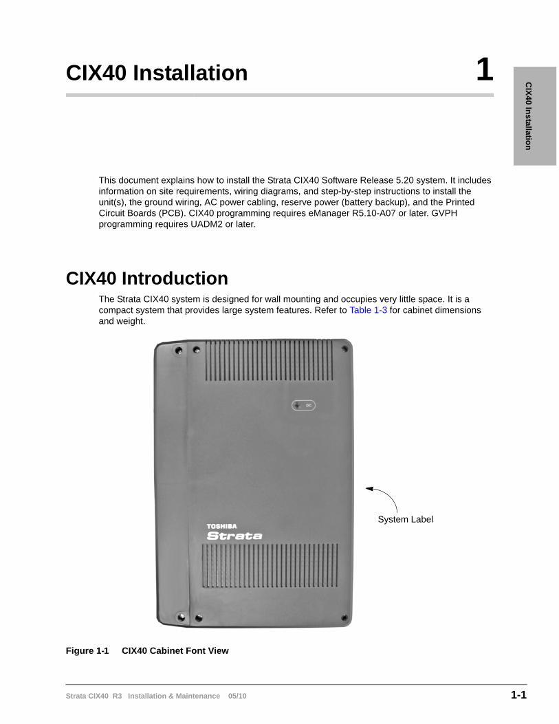
CIX40 IntroductionThe Strata CIX40 system is designed for wall mounting and occupies very little space. It is a compact system that provides large system features. Refer to Table 1-3 for cabinet dimensions and weight.
Figure 1-1 CIX40 Cabinet Font View
System Label
CIX40 InstallationCIX40 System Cabinet Versions
1-2 Strata CIX40 R3 Installation & Maintenance 05/10
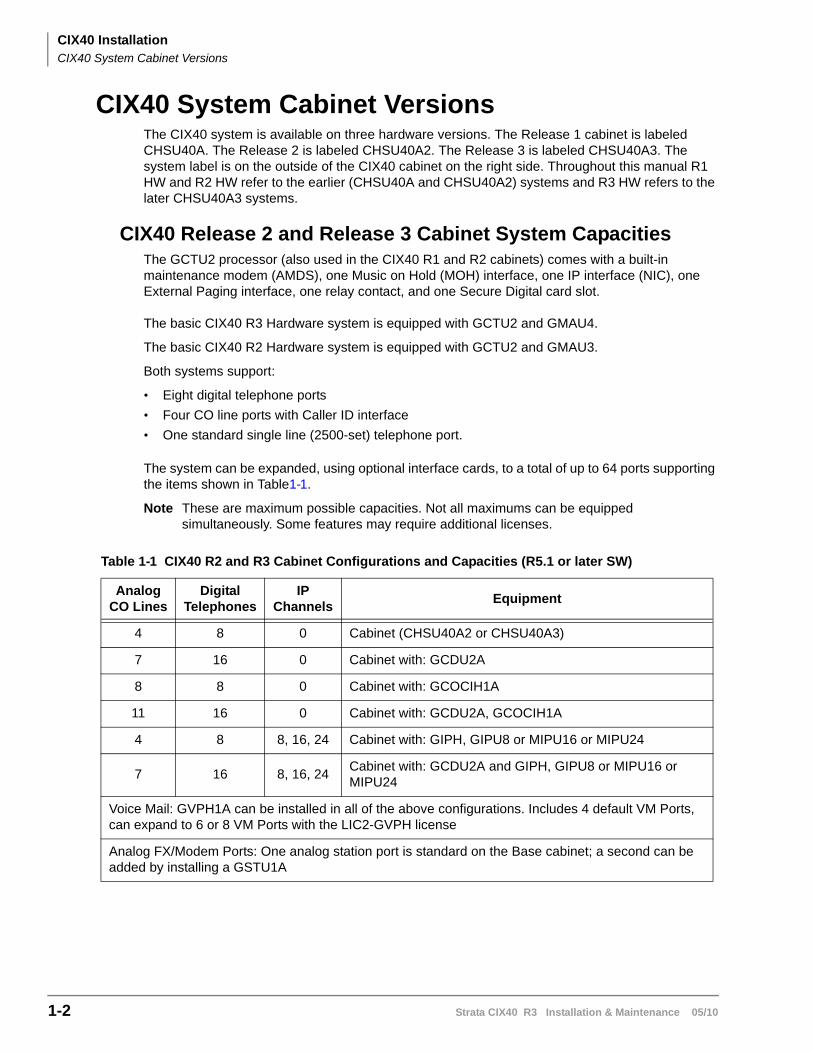
CIX40 System Cabinet VersionsThe CIX40 system is available on three hardware versions. The Release 1 cabinet is labeled CHSU40A. The Release 2 is labeled CHSU40A2. The Release 3 is labeled CHSU40A3. The system label is on the outside of the CIX40 cabinet on the right side. Throughout this manual R1 HW and R2 HW refer to the earlier (CHSU40A and CHSU40A2) systems and R3 HW refers to the later CHSU40A3 systems.
CIX40 Release 2 and Release 3 Cabinet System CapacitiesThe GCTU2 processor (also used in the CIX40 R1 and R2 cabinets) comes with a built-in maintenance modem (AMDS), one Music on Hold (MOH) interface, one IP interface (NIC), one External Paging interface, one relay contact, and one Secure Digital card slot.
The basic CIX40 R3 Hardware system is equipped with GCTU2 and GMAU4.
The basic CIX40 R2 Hardware system is equipped with GCTU2 and GMAU3.
Both systems support:
• Eight digital telephone ports
• Four CO line ports with Caller ID interface
• One standard single line (2500-set) telephone port.
The system can be expanded, using optional interface cards, to a total of up to 64 ports supporting the items shown in Table1-1.
Note These are maximum possible capacities. Not all maximums can be equipped simultaneously. Some features may require additional licenses.
Table 1-1 CIX40 R2 and R3 Cabinet Configurations and Capacities (R5.1 or later SW)
Analog CO Lines
Digital Telephones
IP Channels
Equipment
4 8 0 Cabinet (CHSU40A2 or CHSU40A3)
7 16 0 Cabinet with: GCDU2A
8 8 0 Cabinet with: GCOCIH1A
11 16 0 Cabinet with: GCDU2A, GCOCIH1A
4 8 8, 16, 24 Cabinet with: GIPH, GIPU8 or MIPU16 or MIPU24
7 16 8, 16, 24Cabinet with: GCDU2A and GIPH, GIPU8 or MIPU16 or MIPU24
Voice Mail: GVPH1A can be installed in all of the above configurations. Includes 4 default VM Ports, can expand to 6 or 8 VM Ports with the LIC2-GVPH license
Analog FX/Modem Ports: One analog station port is standard on the Base cabinet; a second can be added by installing a GSTU1A
CIX40 InstallationCIX40 System Cabinet Versions
Strata CIX40 R3 Installation & Maintenance 05/10 1-3
CIX
40 In
stallation
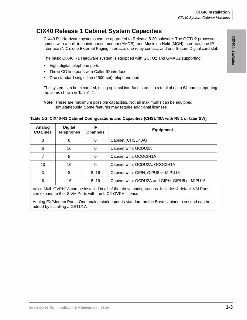
CIX40 Release 1 Cabinet System CapacitiesCIX40 R1 Hardware systems can be upgraded to Release 5.20 software. The GCTU2 processor comes with a built-in maintenance modem (AMDS), one Music on Hold (MOH) interface, one IP interface (NIC), one External Paging interface, one relay contact, and one Secure Digital card slot.
The basic CIX40 R1 Hardware system is equipped with GCTU2 and GMAU2 supporting:
• Eight digital telephone ports
• Three CO line ports with Caller ID interface
• One standard single line (2500-set) telephone port.
The system can be expanded, using optional interface cards, to a total of up to 64 ports supporting the items shown in Table1-2.
Note These are maximum possible capacities. Not all maximums can be equipped simultaneously. Some features may require additional licenses.
Table 1-2 CIX40-R1 Cabinet Configurations and Capacities (CHSU40A with R5.1 or later SW)
Analog CO Lines
Digital Telephones
IP Channels
Equipment
3 8 0 Cabinet (CHSU40A)
6 16 0 Cabinet with: GCDU2A
7 8 0 Cabinet with: GCOCIH1A
10 16 0 Cabinet with: GCDU2A, GCOCIH1A
3 8 8, 16 Cabinet with: GIPH, GIPU8 or MIPU16
6 16 8, 16 Cabinet with: GCDU2A and GIPH, GIPU8 or MIPU16
Voice Mail: GVPH1A can be installed in all of the above configurations. Includes 4 default VM Ports, can expand to 6 or 8 VM Ports with the LIC2-GVPH license
Analog FX/Modem Ports: One analog station port is standard on the Base cabinet; a second can be added by installing a GSTU1A
CIX40 InstallationCIX40 R5.20 Software
1-4 Strata CIX40 R3 Installation & Maintenance 05/10
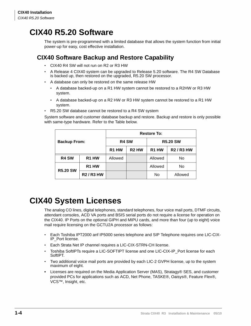
CIX40 R5.20 SoftwareThe system is pre-programmed with a limited database that allows the system function from initial power-up for easy, cost effective installation.
CIX40 Software Backup and Restore Capability• CIX40 R4 SW will not run on R2 or R3 HW
• A Release 4 CIX40 system can be upgraded to Release 5.20 software. The R4 SW Database is backed up, then restored on the upgraded, R5.20 SW processor.
• A database can only be restored on the same release HW
• A database backed-up on a R1 HW system cannot be restored to a R2HW or R3 HW system.
• A database backed-up on a R2 HW or R3 HW system cannot be restored to a R1 HW system.
• R5.20 SW database cannot be restored to a R4 SW system
System software and customer database backup and restore. Backup and restore is only possible with same-type hardware. Refer to the Table below.
CIX40 System LicensesThe analog CO lines, digital telephones, standard telephones, four voice mail ports, DTMF circuits, attendant consoles, ACD VA ports and BSIS serial ports do not require a license for operation on the CIX40. IP Ports on the optional GIPH and MIPU cards, and more than four (up to eight) voice mail require licensing on the GCTU2A processor as follows:
• Each Toshiba IPT2000 anf IP5000 series telephone and SIP Telephone requires one LIC-CIX-IP_Port license.
• Each Strata Net IP channel requires a LIC-CIX-STRN-CH license.
• Toshiba SoftIPTs require a LIC-SOFTIPT license and one LIC-CIX-IP_Port license for each SoftIPT.
• Two additional voice mail ports are provided by each LIC-2 GVPH license, up to the system maximum of eight.
• Licenses are required on the Media Application Server (MAS), Stratagy® SES, and customer provided PCs for applications such as ACD, Net Phone, TASKE®, Oaisys®, Feature Flex®, VCS™, Insight, etc.
Backup From:
Restore To:
R4 SW R5.20 SW
R1 HW R2 HW R1 HW R2 / R3 HW
R4 SW R1 HW Allowed Allowed No
R5.20 SWR1 HW Allowed No
R2 / R3 HW No Allowed
CIX40 InstallationCIX40 Cabinet Specifications
Strata CIX40 R3 Installation & Maintenance 05/10 1-5
CIX
40 In
stallation
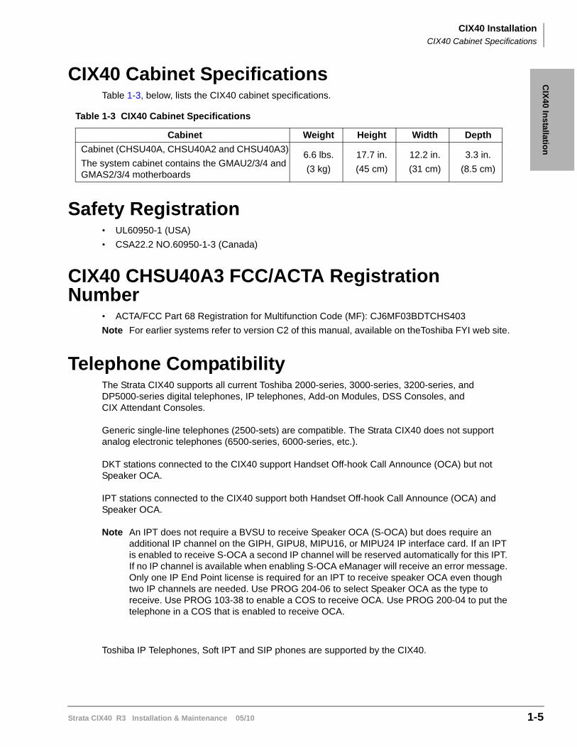
CIX40 Cabinet SpecificationsTable 1-3, below, lists the CIX40 cabinet specifications.
Safety Registration• UL60950-1 (USA)
• CSA22.2 NO.60950-1-3 (Canada)
CIX40 CHSU40A3 FCC/ACTA Registration Number
• ACTA/FCC Part 68 Registration for Multifunction Code (MF): CJ6MF03BDTCHS403
Note For earlier systems refer to version C2 of this manual, available on theToshiba FYI web site.
Telephone CompatibilityThe Strata CIX40 supports all current Toshiba 2000-series, 3000-series, 3200-series, and DP5000-series digital telephones, IP telephones, Add-on Modules, DSS Consoles, and CIX Attendant Consoles.
Generic single-line telephones (2500-sets) are compatible. The Strata CIX40 does not support analog electronic telephones (6500-series, 6000-series, etc.).
DKT stations connected to the CIX40 support Handset Off-hook Call Announce (OCA) but not Speaker OCA.
IPT stations connected to the CIX40 support both Handset Off-hook Call Announce (OCA) and Speaker OCA.
Note An IPT does not require a BVSU to receive Speaker OCA (S-OCA) but does require an additional IP channel on the GIPH, GIPU8, MIPU16, or MIPU24 IP interface card. If an IPT is enabled to receive S-OCA a second IP channel will be reserved automatically for this IPT. If no IP channel is available when enabling S-OCA eManager will receive an error message. Only one IP End Point license is required for an IPT to receive speaker OCA even though two IP channels are needed. Use PROG 204-06 to select Speaker OCA as the type to receive. Use PROG 103-38 to enable a COS to receive OCA. Use PROG 200-04 to put the telephone in a COS that is enabled to receive OCA.
Toshiba IP Telephones, Soft IPT and SIP phones are supported by the CIX40.
Table 1-3 CIX40 Cabinet Specifications
Cabinet Weight Height Width Depth
Cabinet (CHSU40A, CHSU40A2 and CHSU40A3)
The system cabinet contains the GMAU2/3/4 and GMAS2/3/4 motherboards
6.6 lbs.
(3 kg)
17.7 in.
(45 cm)
12.2 in.
(31 cm)
3.3 in.
(8.5 cm)
CIX40 InstallationTelephone Compatibility
1-6 Strata CIX40 R3 Installation & Maintenance 05/10
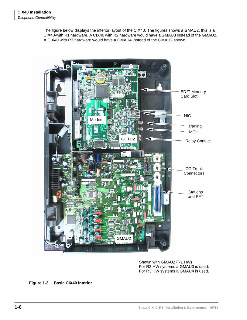
The figure below displays the interior layout of the CIX40. The figures shows a GMAU2, this is a CIX40-with R1 hardware. A CIX40 with R2 hardware would have a GMAU3 instead of the GMAU2. A CIX40 with R3 hardware would have a GMAU4 instead of the GMAU2 shown.
Figure 1-2 Basic CIX40 Interior
CO Trunk
Stations
MOH
Paging
NIC
SD™ Memory
Relay Contact
Modem
Connectors
and PFT
GCTU2
GMAU2
Card Slot
Shown with GMAU2 (R1 HW)For R2 HW systems a GMAU3 is used.For R3 HW systems a GMAU4 is used.
CIX40 InstallationInspection
Strata CIX40 R3 Installation & Maintenance 05/10 1-7
CIX
40 In
stallation
Inspection1. When the system is received, examine all packages carefully and note any visible damage. If
any damage is found, do not open the packages. Contact the delivery carrier immediately and make the proper claims.
2. After unpacking (and before installing), check the system against the packing list and inspect all equipment for damage. If equipment is missing or damaged, contact your supplier immediately.
3. Be sure to retain original packaging materials for re-use when storing or transporting system hardware.
Packaging and StorageCAUTION! When handling (installing, removing, examining) PCBs, do not touch the
back (soldered) side or edge connector. Always hold the PCB by its edges.
When packaging and storing the system, remove PCBs from the system cabinet. PCBs should be packaged in their original antistatic bags for protection against electrostatic discharge. Be sure to package equipment in its original shipping containers.
CIX40 InstallationSite Requirements
1-8 Strata CIX40 R3 Installation & Maintenance 05/10
Site RequirementsThis section defines the installation site requirements necessary to ensure a proper operating environment for the CIX40. Also included are grounding requirements.
Input PowerThe system requires an input power source of 115VAC ± 10VAC, 50/60 Hz, 1.5 amps. The AC outlet is recommended to be dedicated and unswitched. (See “AC Power and Grounding Requirements” on page 1-10.)
A dedicated AC power circuit eliminates interference from branch circuit motor noise or the like, and to prevent accidental power-off. To avoid accidental power turn-off, Toshiba recommends that you do not use an On/Off wall switch on this dedicated AC circuit.
For the Strata CIX40, a reserve power source (HPFB-6) may be connected to the system to serve as a power failure backup (See Step 1 on page 1-43).
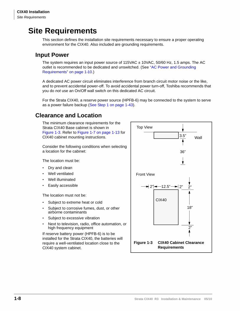
Clearance and LocationThe minimum clearance requirements for the Strata CIX40 Base cabinet is shown in Figure 1-3. Refer to Figure 1-7 on page 1-13 for CIX40 cabinet mounting instructions.
Consider the following conditions when selecting a location for the cabinet:
The location must be:
• Dry and clean
• Well ventilated
• Well illuminated
• Easily accessible
The location must not be:
• Subject to extreme heat or cold
• Subject to corrosive fumes, dust, or other airborne contaminants
• Subject to excessive vibration
• Next to television, radio, office automation, or high frequency equipment
If reserve battery power (HPFB-6) is to be installed for the Strata CIX40, the batteries will require a well-ventilated location close to the CIX40 system cabinet.
Figure 1-3 CIX40 Cabinet Clearance Requirements
Top View
Front View
Wall
2” 12.5”
18”
2” 2”
2”
3.5”
CIX40
36”
CIX40 InstallationSite Requirements
Strata CIX40 R3 Installation & Maintenance 05/10 1-9
CIX
40 In
stallation
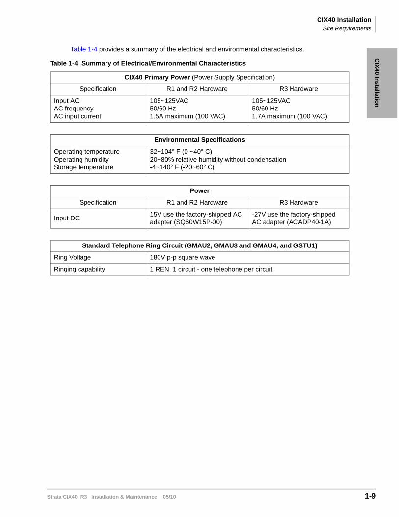
Table 1-4 provides a summary of the electrical and environmental characteristics.
Table 1-4 Summary of Electrical/Environmental Characteristics
CIX40 Primary Power (Power Supply Specification)
Specification R1 and R2 Hardware R3 Hardware
Input ACAC frequencyAC input current
105~125VAC50/60 Hz1.5A maximum (100 VAC)
105~125VAC50/60 Hz1.7A maximum (100 VAC)
Environmental Specifications
Operating temperatureOperating humidityStorage temperature
32~104° F (0 ~40° C)20~80% relative humidity without condensation-4~140° F (-20~60° C)
Power
Specification R1 and R2 Hardware R3 Hardware
Input DC15V use the factory-shipped AC adapter (SQ60W15P-00)
-27V use the factory-shipped AC adapter (ACADP40-1A)
Standard Telephone Ring Circuit (GMAU2, GMAU3 and GMAU4, and GSTU1)
Ring Voltage 180V p-p square wave
Ringing capability 1 REN, 1 circuit - one telephone per circuit
CIX40 InstallationAC Power and Grounding Requirements
1-10 Strata CIX40 R3 Installation & Maintenance 05/10
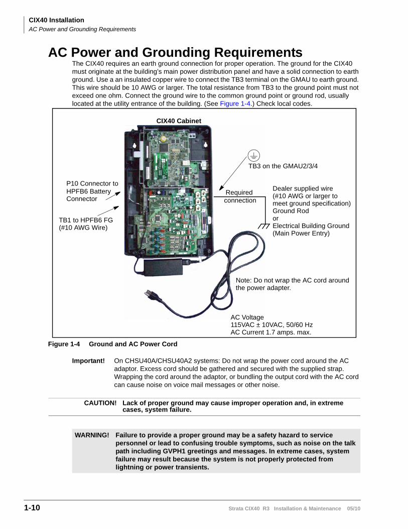
AC Power and Grounding RequirementsThe CIX40 requires an earth ground connection for proper operation. The ground for the CIX40 must originate at the building’s main power distribution panel and have a solid connection to earth ground. Use a an insulated copper wire to connect the TB3 terminal on the GMAU to earth ground. This wire should be 10 AWG or larger. The total resistance from TB3 to the ground point must not exceed one ohm. Connect the ground wire to the common ground point or ground rod, usually located at the utility entrance of the building. (See Figure 1-4.) Check local codes.
Figure 1-4 Ground and AC Power Cord
Important! On CHSU40A/CHSU40A2 systems: Do not wrap the power cord around the AC adaptor. Excess cord should be gathered and secured with the supplied strap. Wrapping the cord around the adaptor, or bundling the output cord with the AC cord can cause noise on voice mail messages or other noise.
CAUTION! Lack of proper ground may cause improper operation and, in extreme cases, system failure.
WARNING! Failure to provide a proper ground may be a safety hazard to service personnel or lead to confusing trouble symptoms, such as noise on the talk path including GVPH1 greetings and messages. In extreme cases, system failure may result because the system is not properly protected from lightning or power transients.
TB3 on the GMAU2/3/4
Dealer supplied wire(#10 AWG or larger tomeet ground specification)Ground RodorElectrical Building Ground(Main Power Entry)
AC Voltage115VAC ± 10VAC, 50/60 HzAC Current 1.7 amps. max.
P10 Connector toHPFB6 Battery
TB1 to HPFB6 FG(#10 AWG Wire)
CIX40 Cabinet
RequiredconnectionConnector
Note: Do not wrap the AC cord aroundthe power adapter.
CIX40 InstallationAC Power and Grounding Requirements
Strata CIX40 R3 Installation & Maintenance 05/10 1-11
CIX
40 In
stallation
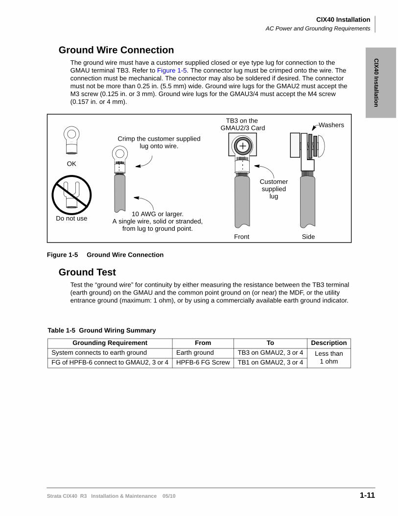
Ground Wire ConnectionThe ground wire must have a customer supplied closed or eye type lug for connection to the GMAU terminal TB3. Refer to Figure 1-5. The connector lug must be crimped onto the wire. The connection must be mechanical. The connector may also be soldered if desired. The connector must not be more than 0.25 in. (5.5 mm) wide. Ground wire lugs for the GMAU2 must accept the M3 screw (0.125 in. or 3 mm). Ground wire lugs for the GMAU3/4 must accept the M4 screw (0.157 in. or 4 mm).
Figure 1-5 Ground Wire Connection
Ground TestTest the “ground wire” for continuity by either measuring the resistance between the TB3 terminal (earth ground) on the GMAU and the common point ground on (or near) the MDF, or the utility entrance ground (maximum: 1 ohm), or by using a commercially available earth ground indicator.
Table 1-5 Ground Wiring Summary
Grounding Requirement From To Description
System connects to earth ground Earth ground TB3 on GMAU2, 3 or 4 Less than 1 ohmFG of HPFB-6 connect to GMAU2, 3 or 4 HPFB-6 FG Screw TB1 on GMAU2, 3 or 4
OK
Do not use
Crimp the customer supplied
TB3 on the Washers
Customersupplied
Front Side
lug
lug onto wire.
10 AWG or larger.A single wire, solid or stranded,
from lug to ground point.
GMAU2/3 Card
CIX40 InstallationInstalling the CIX40 Cabinet
1-12 Strata CIX40 R3 Installation & Maintenance 05/10
Installing the CIX40 CabinetCheck the items shipped.
• CHSU40A (R1 HW), CHSU40A2 (R2 HW), or CHSU40A3 (R3 HW) cabinet
• GMAU2 (R1 HW), GMAU3 (R2 HW) or GMAU4 (R3 HW) motherboard and GCTU2 processor PCB
• AC adapter
• Tie wrap for cable clamp
• Tie wrap for AC adapter
• Velcro strap for AC adapter cord
Step 1: Mount the Cabinet on the Wall
The Base cabinet is designed to be mounted on a wall or other vertical surface.
To mount the CIX40 Cabinet
1. Make sure the location for the CIX40 meets the minimum clearance requirements specified in Figure 1-3 on page 1-8.
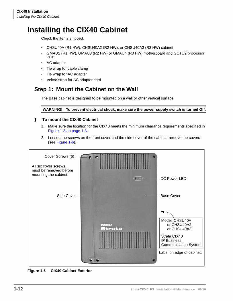
2. Loosen the screws on the front cover and the side cover of the cabinet, remove the covers (see Figure 1-6).
Figure 1-6 CIX40 Cabinet Exterior
WARNING! To prevent electrical shock, make sure the power supply switch is turned Off.
Cover Screws (6)
Side Cover
DC Power LED
Base Cover
Model: CHSU40A
Label on edge of cabinet.
All six cover screwsmust be removed beforemounting the cabinet.
or CHSU40A2
Strata CIX40IP BusinessCommunication System
or CHSU40A3
CIX40 InstallationInstalling the CIX40 Cabinet
Strata CIX40 R3 Installation & Maintenance 05/10 1-13
CIX
40 In
stallation
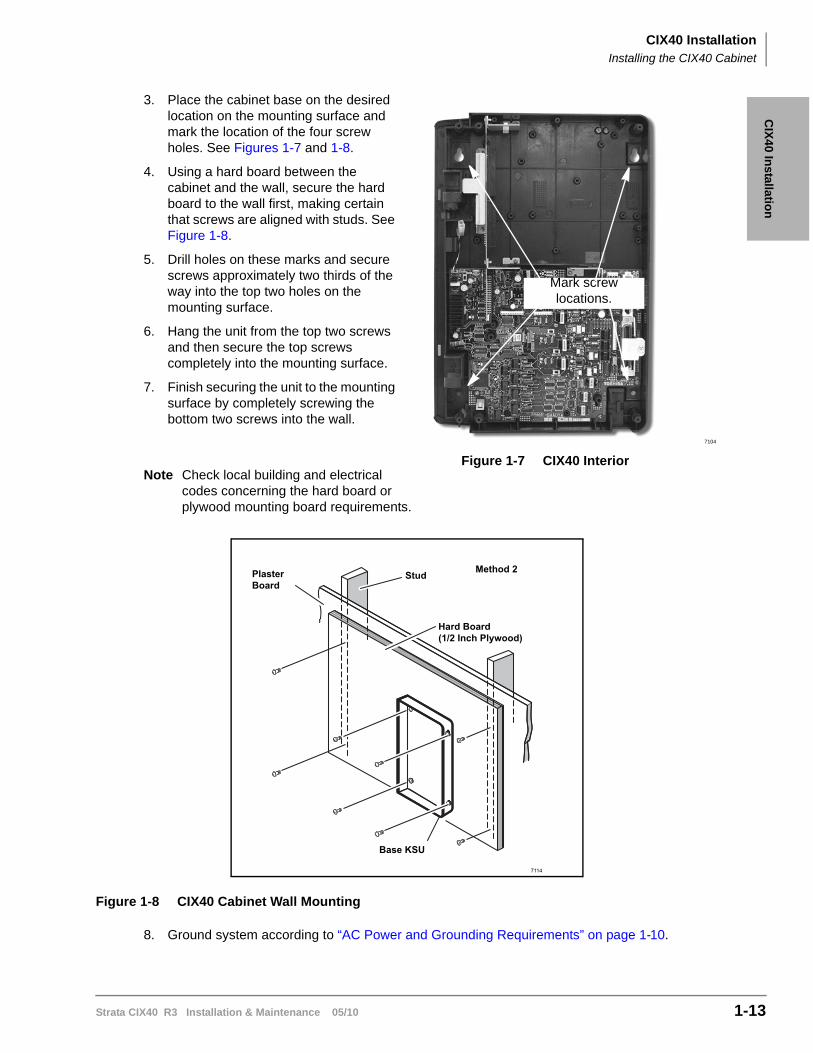
3. Place the cabinet base on the desired location on the mounting surface and mark the location of the four screw holes. See Figures 1-7 and 1-8.
4. Using a hard board between the cabinet and the wall, secure the hard board to the wall first, making certain that screws are aligned with studs. See Figure 1-8.
5. Drill holes on these marks and secure screws approximately two thirds of the way into the top two holes on the mounting surface.
6. Hang the unit from the top two screws and then secure the top screws completely into the mounting surface.
7. Finish securing the unit to the mounting surface by completely screwing the bottom two screws into the wall.
Note Check local building and electrical codes concerning the hard board or plywood mounting board requirements.
Figure 1-8 CIX40 Cabinet Wall Mounting
8. Ground system according to “AC Power and Grounding Requirements” on page 1-10.
7104
Figure 1-7 CIX40 Interior
Mark screw locations.
Method 2StudPlasterBoard
Hard Board(1/2 Inch Plywood)
Base KSU
7114
CIX40 InstallationInstalling the CIX40 Cabinet
1-14 Strata CIX40 R3 Installation & Maintenance 05/10
Step 1: Install Power Wiring
Important! Ensure that you have the correct power adapter for the cabinet being installed.R1 and R2 HW (GMAU2/3) use factory-shipped AC adapter SQ60W15P-00R3 HW (GMAU4) use factory-shipped AC adapter ACADP40-1A
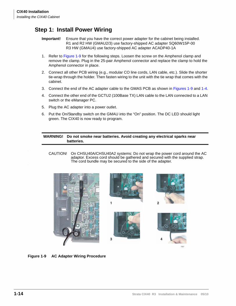
1. Refer to Figure 1-9 for the following steps. Loosen the screw on the Amphenol clamp and remove the clamp. Plug in the 25-pair Amphenol connector and replace the clamp to hold the Amphenol connector in place.
2. Connect all other PCB wiring (e.g., modular CO line cords, LAN cable, etc.). Slide the shorter tie-wrap through the holder. Then fasten wiring to the unit with the tie wrap that comes with the cabinet.
3. Connect the end of the AC adapter cable to the GMAS PCB as shown in Figures 1-9 and 1-4.
4. Connect the other end of the GCTU2 (100Base TX) LAN cable to the LAN connected to a LAN switch or the eManager PC.
5. Plug the AC adapter into a power outlet.
6. Put the On/Standby switch on the GMAU into the “On” position. The DC LED should light green. The CIX40 is now ready to program.
CAUTION! On CHSU40A/CHSU40A2 systems: Do not wrap the power cord around the AC adaptor. Excess cord should be gathered and secured with the supplied strap. The cord bundle may be secured to the side of the adapter.
Figure 1-9 AC Adapter Wiring Procedure
WARNING! Do not smoke near batteries. Avoid creating any electrical sparks near batteries.
1
3 4
2
7257
CIX40 InstallationCIX40 Cabinet Slots
Strata CIX40 R3 Installation & Maintenance 05/10 1-15
CIX
40 In
stallation
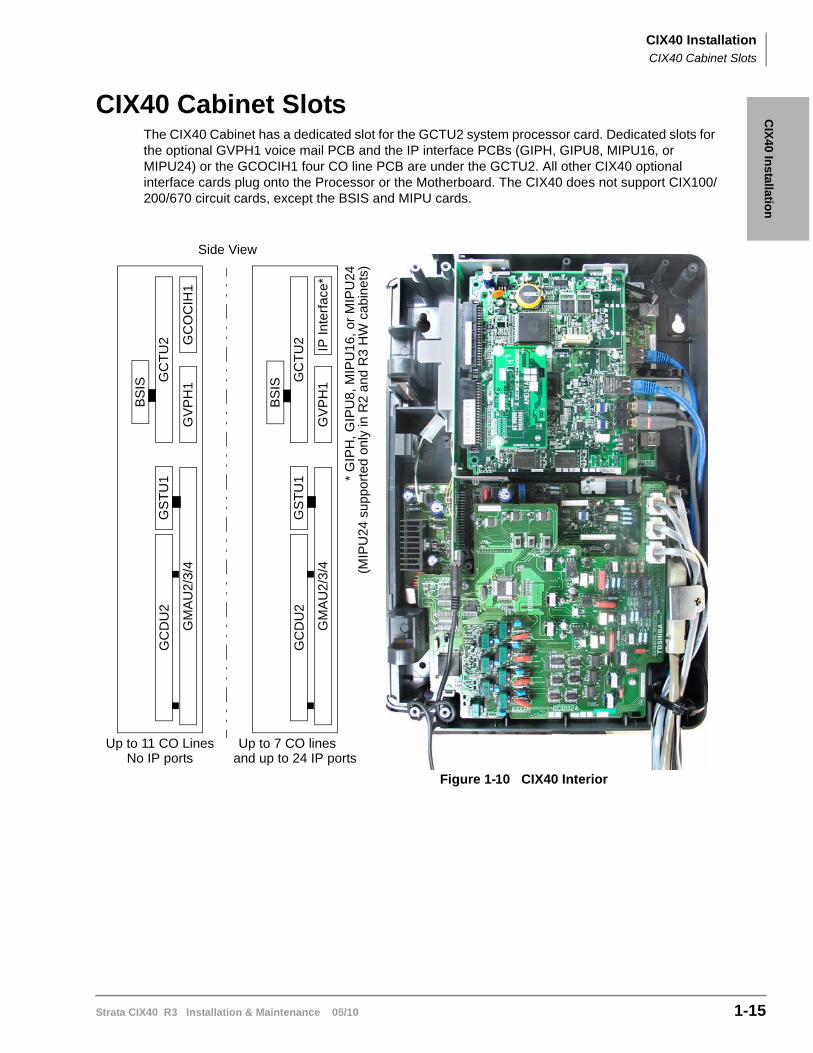
CIX40 Cabinet SlotsThe CIX40 Cabinet has a dedicated slot for the GCTU2 system processor card. Dedicated slots for the optional GVPH1 voice mail PCB and the IP interface PCBs (GIPH, GIPU8, MIPU16, or MIPU24) or the GCOCIH1 four CO line PCB are under the GCTU2. All other CIX40 optional interface cards plug onto the Processor or the Motherboard. The CIX40 does not support CIX100/200/670 circuit cards, except the BSIS and MIPU cards.
Figure 1-10 CIX40 Interior
GM
AU
2/3
/4
GC
TU
2G
CD
U2
IP In
terf
ace*
BS
IS
GS
TU
1
GV
PH
1
GM
AU
2/3
/4
GC
TU
2G
CD
U2
GC
OC
IH1
BS
IS
GS
TU
1
GV
PH
1
Up to 11 CO LinesNo IP ports and up to 24 IP ports
Up to 7 CO lines
* G
IPH
, GIP
U8
, M
IPU
16,
or
MIP
U2
4
Side View
(MIP
U24
sup
por
ted
only
in R
2 a
nd
R3
HW
ca
bin
ets)
CIX40 InstallationCIX40 Cabinet Slots
1-16 Strata CIX40 R3 Installation & Maintenance 05/10
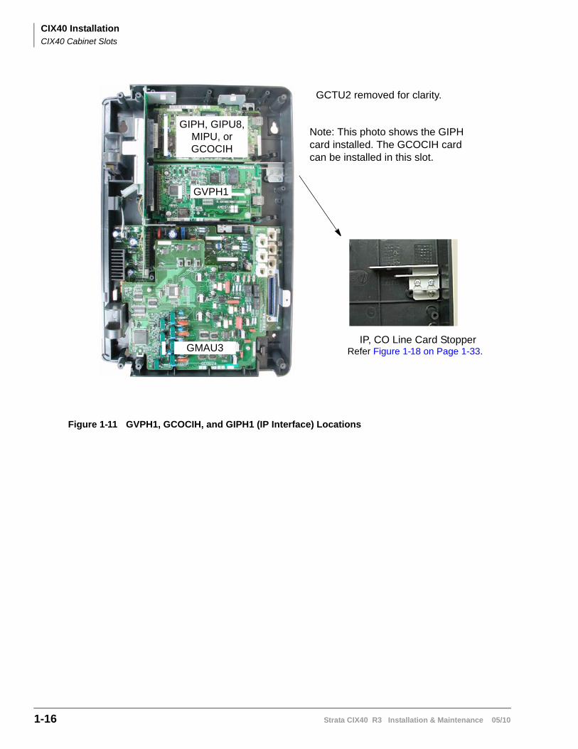
Figure 1-11 GVPH1, GCOCIH, and GIPH1 (IP Interface) Locations
GCTU2 removed for clarity.
GIPH, GIPU8, MIPU, orGCOCIH
GVPH1
GMAU3IP, CO Line Card Stopper
Refer Figure 1-18 on Page 1-33.
Note: This photo shows the GIPHcard installed. The GCOCIH cardcan be installed in this slot.
CIX40 InstallationPrinted Circuit Boards
Strata CIX40 R3 Installation & Maintenance 05/10 1-17
CIX
40 In
stallation
Printed Circuit BoardsThis section contains detailed descriptions of each printed circuit board (PCB) available for the Strata CIX40 system.
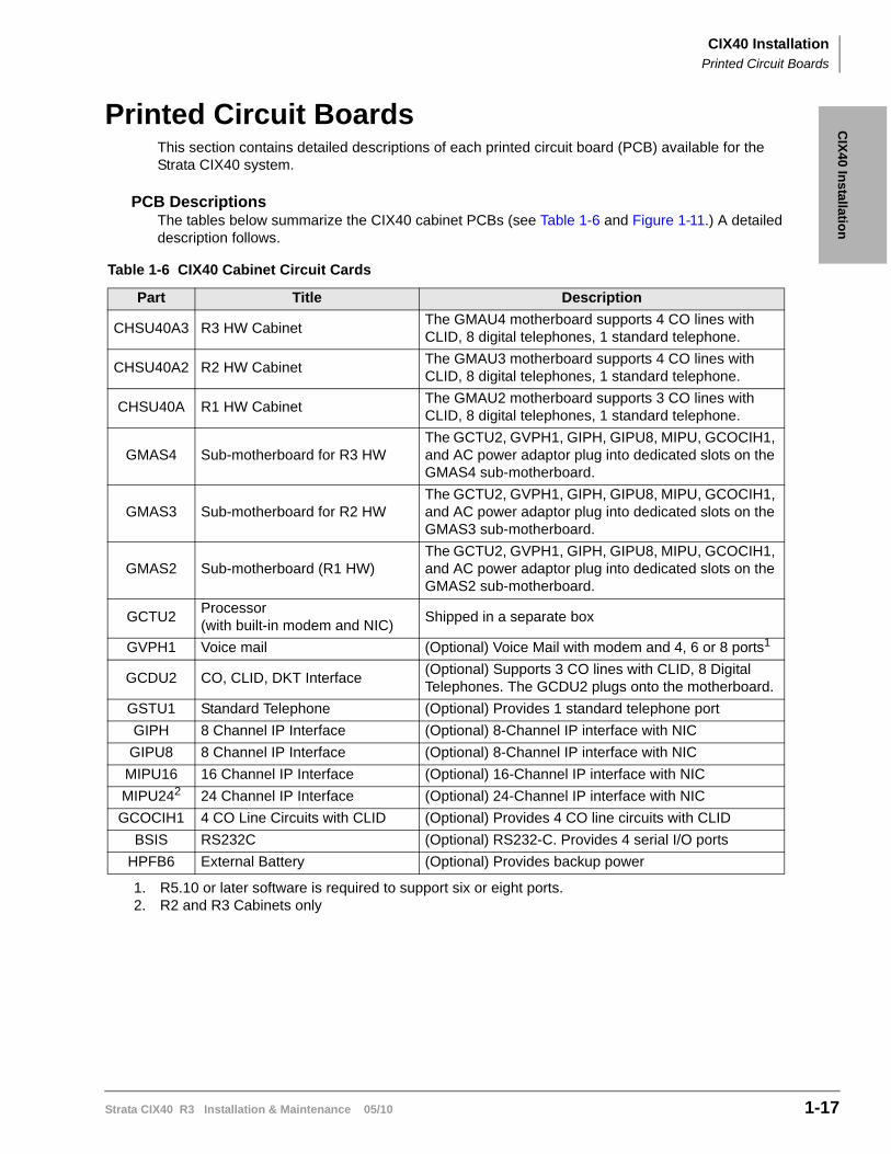
PCB DescriptionsThe tables below summarize the CIX40 cabinet PCBs (see Table 1-6 and Figure 1-11.) A detailed description follows.
Table 1-6 CIX40 Cabinet Circuit Cards
Part Title Description
CHSU40A3 R3 HW CabinetThe GMAU4 motherboard supports 4 CO lines with CLID, 8 digital telephones, 1 standard telephone.
CHSU40A2 R2 HW CabinetThe GMAU3 motherboard supports 4 CO lines with CLID, 8 digital telephones, 1 standard telephone.
CHSU40A R1 HW CabinetThe GMAU2 motherboard supports 3 CO lines with CLID, 8 digital telephones, 1 standard telephone.
GMAS4 Sub-motherboard for R3 HWThe GCTU2, GVPH1, GIPH, GIPU8, MIPU, GCOCIH1, and AC power adaptor plug into dedicated slots on the GMAS4 sub-motherboard.
GMAS3 Sub-motherboard for R2 HWThe GCTU2, GVPH1, GIPH, GIPU8, MIPU, GCOCIH1, and AC power adaptor plug into dedicated slots on the GMAS3 sub-motherboard.
GMAS2 Sub-motherboard (R1 HW)The GCTU2, GVPH1, GIPH, GIPU8, MIPU, GCOCIH1, and AC power adaptor plug into dedicated slots on the GMAS2 sub-motherboard.
GCTU2Processor(with built-in modem and NIC)
Shipped in a separate box
GVPH1 Voice mail (Optional) Voice Mail with modem and 4, 6 or 8 ports1
1. R5.10 or later software is required to support six or eight ports.
GCDU2 CO, CLID, DKT Interface(Optional) Supports 3 CO lines with CLID, 8 Digital Telephones. The GCDU2 plugs onto the motherboard.
GSTU1 Standard Telephone (Optional) Provides 1 standard telephone port
GIPH 8 Channel IP Interface (Optional) 8-Channel IP interface with NIC
GIPU8 8 Channel IP Interface (Optional) 8-Channel IP interface with NIC
MIPU16 16 Channel IP Interface (Optional) 16-Channel IP interface with NIC
MIPU242
2. R2 and R3 Cabinets only
24 Channel IP Interface (Optional) 24-Channel IP interface with NIC
GCOCIH1 4 CO Line Circuits with CLID (Optional) Provides 4 CO line circuits with CLID
BSIS RS232C (Optional) RS232-C. Provides 4 serial I/O ports
HPFB6 External Battery (Optional) Provides backup power
CIX40 InstallationCIX40 Processor
1-18 Strata CIX40 R3 Installation & Maintenance 05/10
CIX40 ProcessorEach CIX40 system operates with one processor card, the GCTU2, installed in a dedicated slot. The CIX40 processor does not require any licenses for standard telephones and trunks. This includes items (line/station ports, DTMF receivers, ABR circuits, etc.). More than four Voice Mail ports, Strata Net IP and all IP endpoints on IP Interface card (GIPH, GIPU8, or MIPU) require additional licenses. Refer to “CIX40 System Licenses” on page 1-4.
The processor card uses a high-speed processor, Dynamic Random Access Memory (DRAM)
working memory, Static Random Access Memory (SRAM) with lithium battery for memory back-up, and flash program memory.
A Secure Digital (SD) card is used for data backup.
The processor supports the following:
• 16 DTMF receivers.
• 16 Busy Tone (BT) detector circuits for Auto Busy Redial (ABR).
• 64 built-in conference circuits.
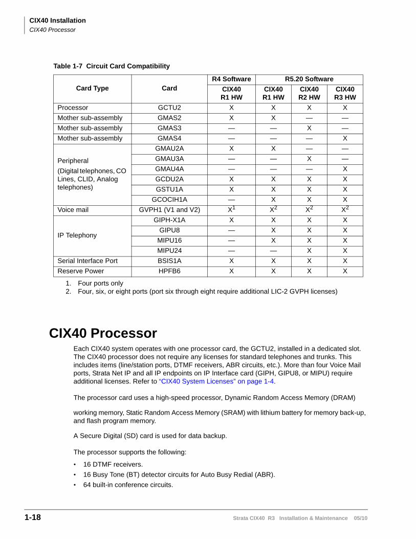
Table 1-7 Circuit Card Compatibility
Card Type CardR4 Software R5.20 Software
CIX40R1 HW
CIX40R1 HW
CIX40R2 HW
CIX40R3 HW
Processor GCTU2 X X X X
Mother sub-assembly GMAS2 X X — —
Mother sub-assembly GMAS3 — — X —
Mother sub-assembly GMAS4 — — — X
Peripheral
(Digital telephones, CO Lines, CLID, Analog telephones)
GMAU2A X X — —
GMAU3A — — X —
GMAU4A — — — X
GCDU2A X X X X
GSTU1A X X X X
GCOCIH1A — X X X
Voice mail GVPH1 (V1 and V2) X1
1. Four ports only
X2
2. Four, six, or eight ports (port six through eight require additional LIC-2 GVPH licenses)
X2 X2
IP Telephony
GIPH-X1A X X X X
GIPU8 — X X X
MIPU16 — X X X
MIPU24 — — X X
Serial Interface Port BSIS1A X X X X
Reserve Power HPFB6 X X X X
CIX40 InstallationCIX40 Processor
Strata CIX40 R3 Installation & Maintenance 05/10 1-19
CIX
40 In
stallation
GCTU2 Processor Interfaces
Administration InterfaceThe processor card has both a built-in modem (AMDS card) and a Network Interface Connector. Either can be used to connect to CIX eManager R5.10-A07 or later, for local or remote maintenance and administration.
Memory Protection BatteryIf commercial AC power is lost, or if a system is moved or stored without power, the processor has an on-board battery that protects data and the customer’s programmed configuration. This information will be maintained in a powerless system for at least six years.
Relay Control InterfaceAn on-board terminal strip provides an interface to a normally open relay contact which can be programmed to control a Night Bell, door lock or to mute the Background Music (BGM) during an external page.
External Page InterfaceA 600 ohm RCA jack is built into the processor to interface with a Toshiba External Amplified Speaker (HESB or BESCB) or a customer-supplied page amplifier and speaker(s) for external paging, night ring over external page, and external BGM applications.
Music-on-hold/Background Music InterfaceOne 600-ohm RCA jack is provided on the processor to interface with Music-on-Hold (MOH) and/or BGM sources. With the CIX40 you can have up to three MOH/BGM source interfaces. The CIX40 Standard Telephone interfaces can be used to provide up to two MOH/BGM input sources in addition to the processor MOH/BGM interface.
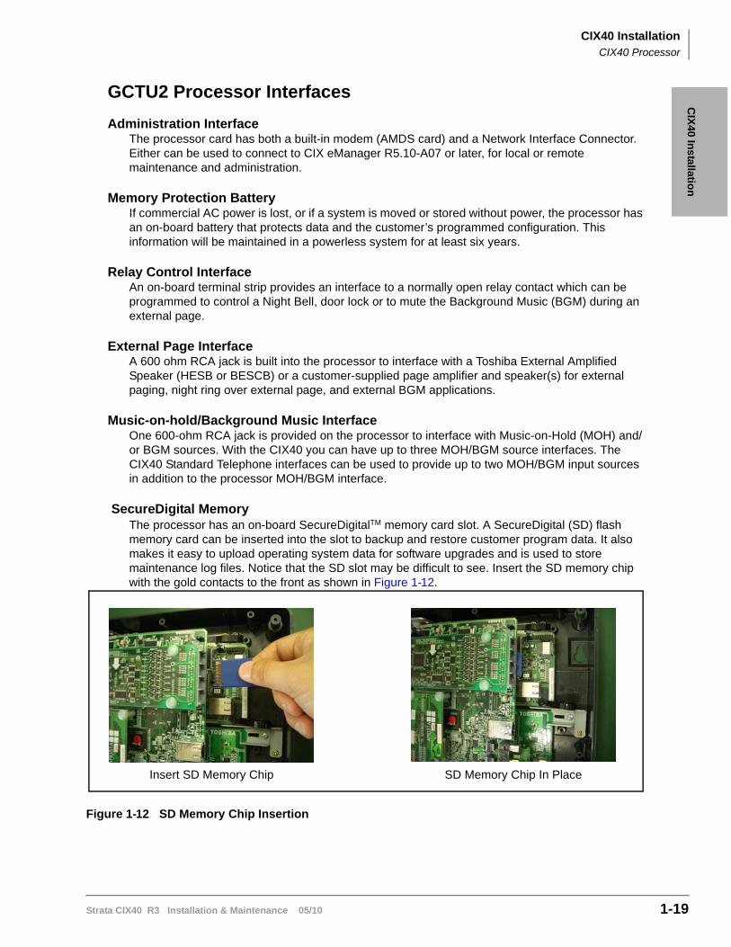
SecureDigital MemoryThe processor has an on-board SecureDigitalTM memory card slot. A SecureDigital (SD) flash memory card can be inserted into the slot to backup and restore customer program data. It also makes it easy to upload operating system data for software upgrades and is used to store maintenance log files. Notice that the SD slot may be difficult to see. Insert the SD memory chip with the gold contacts to the front as shown in Figure 1-12.
Figure 1-12 SD Memory Chip Insertion
Insert SD Memory Chip SD Memory Chip In Place
CIX40 InstallationCIX40 Processor
1-20 Strata CIX40 R3 Installation & Maintenance 05/10
CIX40 Processor Optional SubassemblyOptional BSIS (Serial Port Interface) subassembly – can be attached to the GCTU2 processor to provide up to four RS-232 interface ports; one port for an SMDR interface to Call Accounting devices, one port for SMDI to external voice mail devices, and two other applications.
Note The GVPH1 does not require a BSIS SMDI port.

CIX40 InstallationIP Interface Cards
Strata CIX40 R3 Installation & Maintenance 05/10 1-21
CIX
40 In
stallation
IP Interface CardsThe features of the CIX40 system IP interface cards are shown in the table below.
Feature GIPH GIPU8 MIPU16 MIPU24
Collect log files remotely NO YES YES YES
Restriction by tail length of Echo Canceller
YES NO NO NO
Quality of Service (QoS) threshold alarm
NO YES YES YES
SIP Trunk Support NO YES YES YES
IP Mobility Support YES1
1. R5.0 or later software required.
YES1 YES1 YES1
Connect between G.711 A-law and G.711 Mu-law codecs
NO YES YES YES
RTP ports used can be user modified
NO YES YES YES
Dual filter echo canceller NO YES YES YES
GIPU8 Circuit Card
CIX40 InstallationGCOCIH
1-22 Strata CIX40 R3 Installation & Maintenance 05/10
GCOCIH The GCOCIH1 assembly provides four loop-start CO line circuits. Refer to Figure 1-19. The GCOCIH1 card plugs into the GMAS sub-mother board. This is the slot adjacent to the voice mail card. When the GCOCIH1 card is installed an IP interface card cannot be installed in the system.
GCOCIH1 assembly specifications:
• Loop-start CO Line Circuits
• DTMF dialing only
• Caller ID Type: ANSI Type 1
• Modem Protocol: Bellcore 202, ITU-T V.23
When the GIPH1, GIPU8, or an MIPU card is installed, a GCOCIH1 (four circuit CO Line interface) cannot be installed.
GCDU2 (DKT and Loop Start Interface)The GCDU2 PCB adds an additional 3 CO lines, 3 Caller ID units, and 8 digital telephone circuits with a single PCB. It attaches to the GMAU4, GMAU3, or GMAU2 motherboard. With the GCDU2 installed, the CIX40 supports up to 16 digital telephones (DKTs), 7 CO lines with Caller ID (GMAU3/4) or 6 CO lines with Caller ID (GMAU2). The GCDU2 does not require a license.
Table 1-8 GCOCIH Controls and Switches
Control/Connector Type of Component Description
SWxxx 2-position slide switches 3dB Pad switch per circuit
Pxxx connector Interface to CCOCIS
P3 Connector Interface to GMAS
Cct 1/2 RJ connector on GCOCIH CO LIne circuits 1 and 2
Cct 3/4 RJ connector on CCOCIS CO LIne circuits 3 and 4
CIX40 InstallationGVPH
Strata CIX40 R3 Installation & Maintenance 05/10 1-23
CIX
40 In
stallation
GVPHThe GVPH is a four, six or eight port voice mail system on a card. The first four port licenses are included in the CIX40 system. Two additional two-port licenses (LIC-2 GVPH) can be added. Earlier versions, the GVPH-V1 card have status indicators for only the first four ports. Later versions, the GVPH-V2 have eight indicators. The two circuit boards are otherwise identical. They both support up to eight voice mail ports in systems running R5.10 and later CIX software.
Note Six and eight port GVPH operation is only supported by CIX40 Release 5.10 and later software.
There are two versions of the GVPH, both versions install in the same manner. All jumpers, selections and indicators are the same.
GSTU1The GSTU1 provides one additional standard telephone interface. The GSTU1 does not require a license. It plugs onto the GMAU PCB.
BSISThe BSIS provides four RS-232 serial ports, it plugs onto the GCTU2 processor PCB.
CIX40 InstallationPCB Installation
1-24 Strata CIX40 R3 Installation & Maintenance 05/10
PCB InstallationOverview Instructions
The following is an overview for installing the Printed Circuit Boards (PCBs) into the Strata CIX40. After reading this section, proceed to the step-by-step instructions for each PCB.
CAUTION! You must remove power from the CIX40 system before installing or removing printed circuit cards.
1. Apply proper settings on the GMAU3 (motherboard).
2. If applicable, set SW6 battery jumper to ON and install the GVPH1 voice mail card(Figures 1-16).
3. If applicable, install, GIPU8, GIPH, MIPU or GCOCIH card.
4. Set P601 battery jumper to ON and install the GCTU2 (processor and Figure 1-22 on Page 1-38).
5. If applicable, install the GCDU2 (3 CO, 3 CLID and 8 DKT circuits Figure 1-23).
6. If applicable, install GSTU1 (standard telephone interface Figure 1-25).
7. If applicable, install the BSIS for SMDR (Figure 1-22).
8. If applicable, install HPFB-6 battery/charger (Figure 1-28).
9. Connect wiring (Table 1-22).
10. Connect AC Adaptor to P2 of the CIX40 sub-motherboard (GMAS, Figures 1-9) and plug the AC Adaptor into AC power.
11. Turn the System ON by sliding the SW1 ON/OFF switch down. The ON/OFF LED located by the GMAU3 label, STANDBY will light.
CIX40 InstallationDetailed PCB Installation
Strata CIX40 R3 Installation & Maintenance 05/10 1-25
CIX
40 In
stallation
Detailed PCB InstallationThis section includes the detailed installation steps for the CIX40 system PCBs.
Step 1: Set Switches on the GMAU2/GMAU3/GMAU4 (Motherboard)
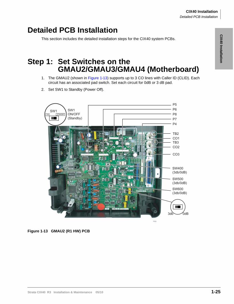
1. The GMAU2 (shown in Figure 1-13) supports up to 3 CO lines with Caller ID (CLID). Each circuit has an associated pad switch. Set each circuit for 0dB or 3 dB pad.
2. Set SW1 to Standby (Power Off).
Figure 1-13 GMAU2 (R1 HW) PCB
7113
SW1 ON/OFF(Standby)
SW400(3db/0dB)
SW500(3db/0dB)
SW600(3db/0dB)
3db 0dB
CO1TB2
P8
TB3CO2
CO3
P6P5
P7P4
ON STANDBYSW1
CIX40 InstallationDetailed PCB Installation
1-26 Strata CIX40 R3 Installation & Maintenance 05/10
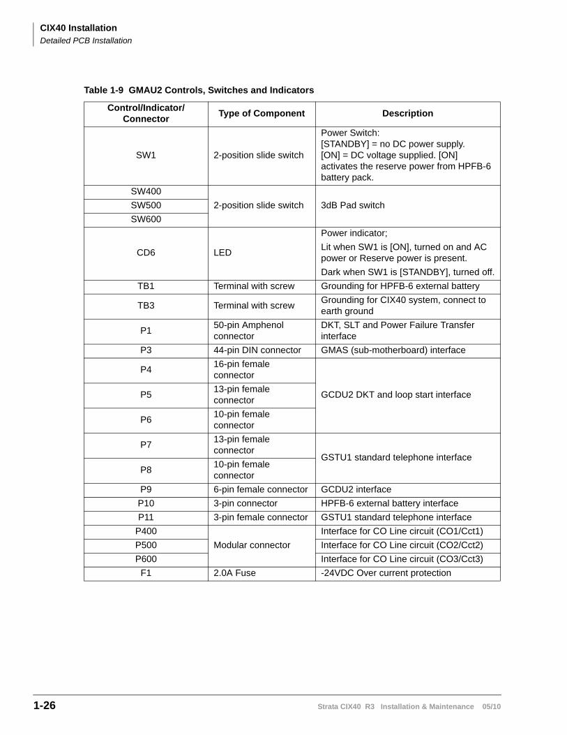
Table 1-9 GMAU2 Controls, Switches and Indicators
Control/Indicator/Connector
Type of Component Description
SW1 2-position slide switch
Power Switch:[STANDBY] = no DC power supply.[ON] = DC voltage supplied. [ON] activates the reserve power from HPFB-6 battery pack.
SW400
2-position slide switch 3dB Pad switchSW500
SW600
CD6 LED
Power indicator;
Lit when SW1 is [ON], turned on and AC power or Reserve power is present.
Dark when SW1 is [STANDBY], turned off.
TB1 Terminal with screw Grounding for HPFB-6 external battery
TB3 Terminal with screwGrounding for CIX40 system, connect to earth ground
P150-pin Amphenol connector
DKT, SLT and Power Failure Transfer interface
P3 44-pin DIN connector GMAS (sub-motherboard) interface
P416-pin female connector
GCDU2 DKT and loop start interfaceP513-pin female connector
P610-pin female connector
P713-pin female connector
GSTU1 standard telephone interfaceP8
10-pin female connector
P9 6-pin female connector GCDU2 interface
P10 3-pin connector HPFB-6 external battery interface
P11 3-pin female connector GSTU1 standard telephone interface
P400
Modular connector
Interface for CO Line circuit (CO1/Cct1)
P500 Interface for CO Line circuit (CO2/Cct2)
P600 Interface for CO Line circuit (CO3/Cct3)
F1 2.0A Fuse -24VDC Over current protection
CIX40 InstallationDetailed PCB Installation
Strata CIX40 R3 Installation & Maintenance 05/10 1-27
CIX
40 In
stallation
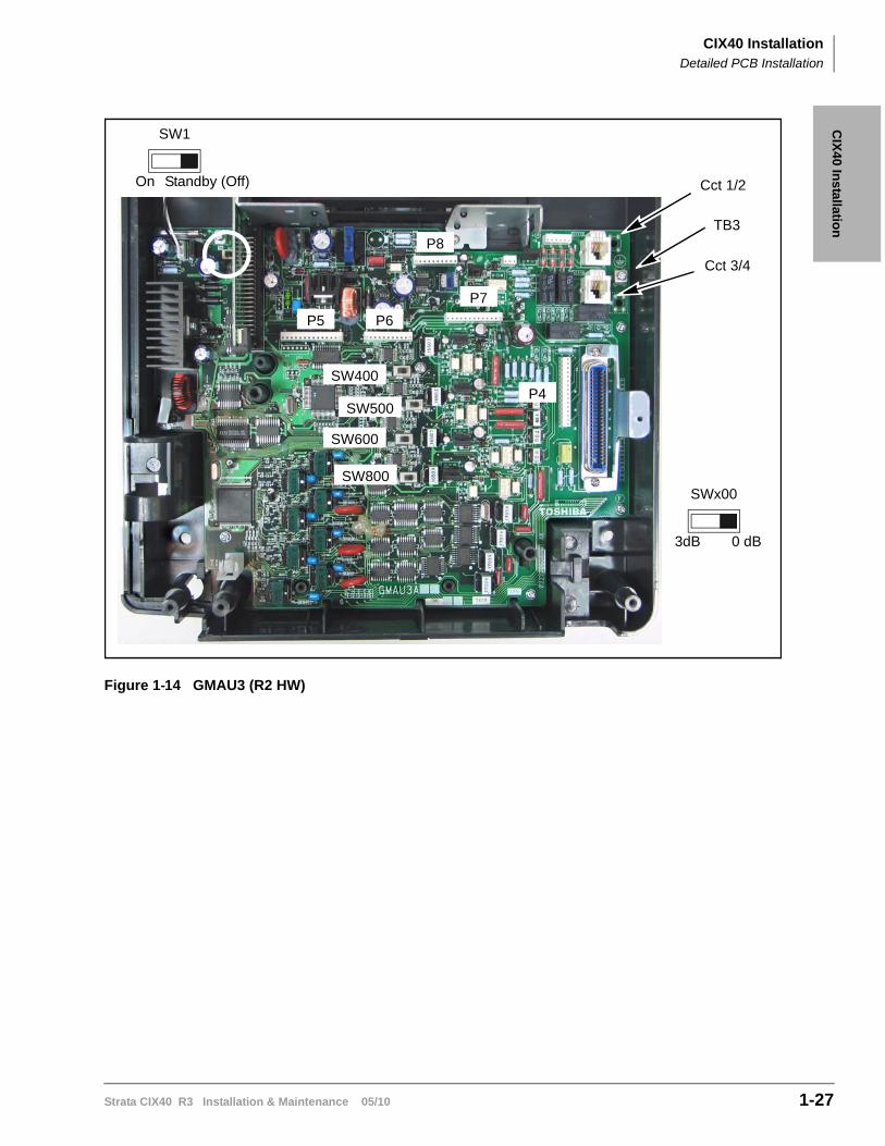
Figure 1-14 GMAU3 (R2 HW)
TB3
Cct 1/2
Cct 3/4
SWx00
3dB
SW500
P5
SW600
SW800
0 dB
SW1
On Standby (Off)
P6
SW400
P8
P4
P7
CIX40 InstallationDetailed PCB Installation
1-28 Strata CIX40 R3 Installation & Maintenance 05/10
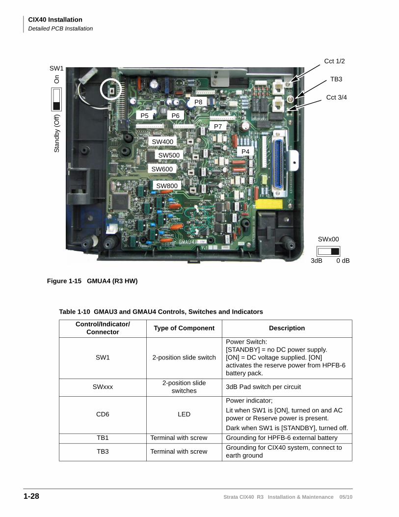
Figure 1-15 GMUA4 (R3 HW)
Table 1-10 GMAU3 and GMAU4 Controls, Switches and Indicators
Control/Indicator/Connector
Type of Component Description
SW1 2-position slide switch
Power Switch:[STANDBY] = no DC power supply.[ON] = DC voltage supplied. [ON] activates the reserve power from HPFB-6 battery pack.
SWxxx2-position slide
switches3dB Pad switch per circuit
CD6 LED
Power indicator;
Lit when SW1 is [ON], turned on and AC power or Reserve power is present.
Dark when SW1 is [STANDBY], turned off.
TB1 Terminal with screw Grounding for HPFB-6 external battery
TB3 Terminal with screwGrounding for CIX40 system, connect to earth ground
TB3
Cct 1/2
Cct 3/4
SWx00
3dB
SW500
P5
SW600
SW800
0 dB
SW1
On
Sta
nd
by (
Off) P6
P8
P4
P7
SW400
CIX40 InstallationDetailed PCB Installation
Strata CIX40 R3 Installation & Maintenance 05/10 1-29
CIX
40 In
stallation
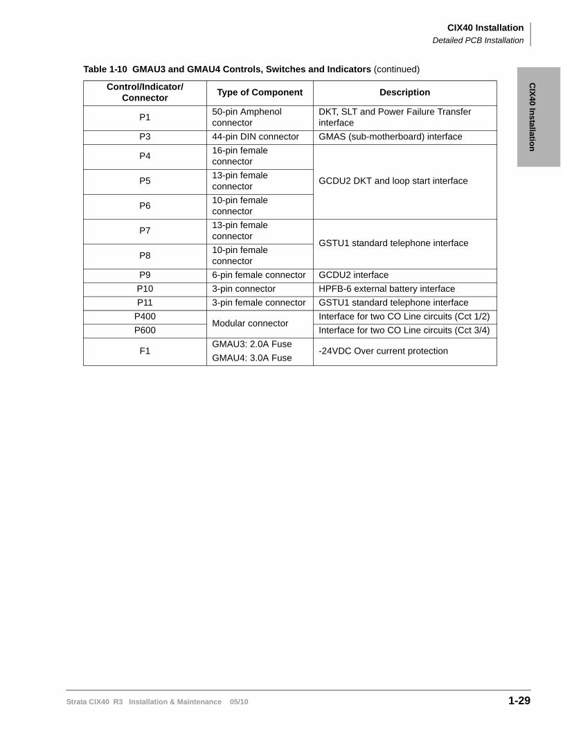
P150-pin Amphenol connector
DKT, SLT and Power Failure Transfer interface
P3 44-pin DIN connector GMAS (sub-motherboard) interface
P416-pin female connector
GCDU2 DKT and loop start interfaceP513-pin female connector
P610-pin female connector
P713-pin female connector
GSTU1 standard telephone interfaceP8
10-pin female connector
P9 6-pin female connector GCDU2 interface
P10 3-pin connector HPFB-6 external battery interface
P11 3-pin female connector GSTU1 standard telephone interface
P400Modular connector
Interface for two CO Line circuits (Cct 1/2)
P600 Interface for two CO Line circuits (Cct 3/4)
F1GMAU3: 2.0A Fuse
GMAU4: 3.0A Fuse-24VDC Over current protection
Table 1-10 GMAU3 and GMAU4 Controls, Switches and Indicators (continued)
Control/Indicator/Connector
Type of Component Description
CIX40 InstallationDetailed PCB Installation
1-30 Strata CIX40 R3 Installation & Maintenance 05/10
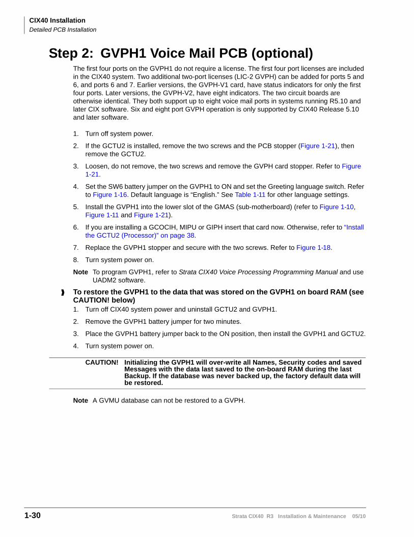
Step 2: GVPH1 Voice Mail PCB (optional)The first four ports on the GVPH1 do not require a license. The first four port licenses are included in the CIX40 system. Two additional two-port licenses (LIC-2 GVPH) can be added for ports 5 and 6, and ports 6 and 7. Earlier versions, the GVPH-V1 card, have status indicators for only the first four ports. Later versions, the GVPH-V2, have eight indicators. The two circuit boards are otherwise identical. They both support up to eight voice mail ports in systems running R5.10 and later CIX software. Six and eight port GVPH operation is only supported by CIX40 Release 5.10 and later software.
1. Turn off system power.
2. If the GCTU2 is installed, remove the two screws and the PCB stopper (Figure 1-21), then remove the GCTU2.
3. Loosen, do not remove, the two screws and remove the GVPH card stopper. Refer to Figure 1-21.
4. Set the SW6 battery jumper on the GVPH1 to ON and set the Greeting language switch. Refer to Figure 1-16. Default language is “English.” See Table 1-11 for other language settings.
5. Install the GVPH1 into the lower slot of the GMAS (sub-motherboard) (refer to Figure 1-10, Figure 1-11 and Figure 1-21).
6. If you are installing a GCOCIH, MIPU or GIPH insert that card now. Otherwise, refer to “Install the GCTU2 (Processor)” on page 38.
7. Replace the GVPH1 stopper and secure with the two screws. Refer to Figure 1-18.
8. Turn system power on.
Note To program GVPH1, refer to Strata CIX40 Voice Processing Programming Manual and use UADM2 software.
To restore the GVPH1 to the data that was stored on the GVPH1 on board RAM (see CAUTION! below)1. Turn off CIX40 system power and uninstall GCTU2 and GVPH1.
2. Remove the GVPH1 battery jumper for two minutes.
3. Place the GVPH1 battery jumper back to the ON position, then install the GVPH1 and GCTU2.
4. Turn system power on.
CAUTION! Initializing the GVPH1 will over-write all Names, Security codes and saved Messages with the data last saved to the on-board RAM during the last Backup. If the database was never backed up, the factory default data will be restored.
Note A GVMU database can not be restored to a GVPH.
CIX40 InstallationDetailed PCB Installation
Strata CIX40 R3 Installation & Maintenance 05/10 1-31
CIX
40 In
stallation
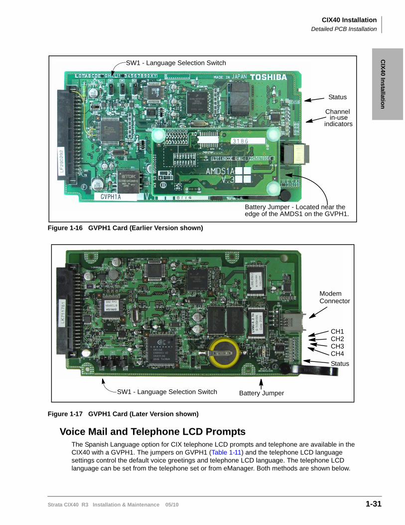
Figure 1-16 GVPH1 Card (Earlier Version shown)
Figure 1-17 GVPH1 Card (Later Version shown)
Voice Mail and Telephone LCD PromptsThe Spanish Language option for CIX telephone LCD prompts and telephone are available in the CIX40 with a GVPH1. The jumpers on GVPH1 (Table 1-11) and the telephone LCD language settings control the default voice greetings and telephone LCD language. The telephone LCD language can be set from the telephone set or from eManager. Both methods are shown below.
Battery Jumper - Located near theedge of the AMDS1 on the GVPH1.
Channelin-use
indicators
SW1 - Language Selection Switch
Status
Battery Jumper
CH1CH2CH3CH4
SW1 - Language Selection Switch
Status
ModemConnector
CIX40 InstallationDetailed PCB Installation
1-32 Strata CIX40 R3 Installation & Maintenance 05/10
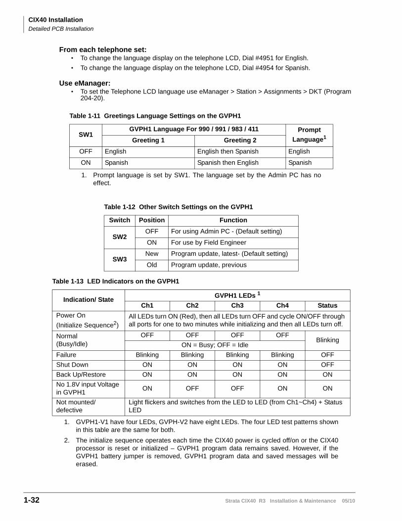
From each telephone set:• To change the language display on the telephone LCD, Dial #4951 for English.
• To change the language display on the telephone LCD, Dial #4954 for Spanish.
Use eManager:• To set the Telephone LCD language use eManager > Station > Assignments > DKT (Program
204-20).
Table 1-11 Greetings Language Settings on the GVPH1
SW1GVPH1 Language For 990 / 991 / 983 / 411 Prompt
Language1
1. Prompt language is set by SW1. The language set by the Admin PC has noeffect.
Greeting 1 Greeting 2
OFF English English then Spanish English
ON Spanish Spanish then English Spanish
Table 1-12 Other Switch Settings on the GVPH1
Switch Position Function
SW2OFF For using Admin PC - (Default setting)
ON For use by Field Engineer
SW3New Program update, latest- (Default setting)
Old Program update, previous
Table 1-13 LED Indicators on the GVPH1
Indication/ StateGVPH1 LEDs 1
1. GVPH1-V1 have four LEDs, GVPH-V2 have eight LEDs. The four LED test patterns shownin this table are the same for both.
Ch1 Ch2 Ch3 Ch4 Status
Power On
(Initialize Sequence2)
2. The initialize sequence operates each time the CIX40 power is cycled off/on or the CIX40processor is reset or initialized – GVPH1 program data remains saved. However, if theGVPH1 battery jumper is removed, GVPH1 program data and saved messages will beerased.
All LEDs turn ON (Red), then all LEDs turn OFF and cycle ON/OFF through all ports for one to two minutes while initializing and then all LEDs turn off.
Normal(Busy/Idle)
OFF OFF OFF OFFBlinking
ON = Busy; OFF = Idle
Failure Blinking Blinking Blinking Blinking OFF
Shut Down ON ON ON ON OFF
Back Up/Restore ON ON ON ON ON
No 1.8V input Voltage in GVPH1
ON OFF OFF ON ON
Not mounted/defective
Light flickers and switches from the LED to LED (from Ch1~Ch4) + Status LED
CIX40 InstallationDetailed PCB Installation
Strata CIX40 R3 Installation & Maintenance 05/10 1-33
CIX
40 In
stallation
Remote ConnectionRemote communication to the GVPH1 requires the installation of a modem on the UADM PC (if a modem does not already exist). The GVPH1 comes equipped with an internal modem (AMDS daughter board) of 33.6 Kbps baud and does not require any additional equipment.
UADM PC ModemPrepare the UADM PC by installing, connecting and configuring a modem. The modem must be capable of communicating at a minimum of 9600 baud.
CAUTION! Internal modems configured for COM ports 3 or 4 are not supported by UADM software.
The UADM PC’s modem connects to the GVPH1 through User ID 993.
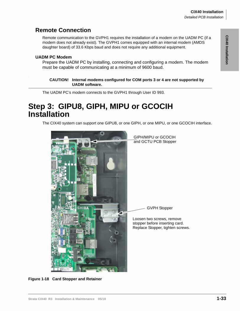
Step 3: GIPU8, GIPH, MIPU or GCOCIH Installation
The CIX40 system can support one GIPU8, or one GIPH, or one MIPU, or one GCOCIH interface.
Figure 1-18 Card Stopper and Retainer
GVPH Stopper
GIPH/MIPU or GCOCIHand GCTU PCB Stopper
Loosen two screws, removestopper before inserting card.Replace Stopper, tighten screws.
CIX40 InstallationDetailed PCB Installation
1-34 Strata CIX40 R3 Installation & Maintenance 05/10
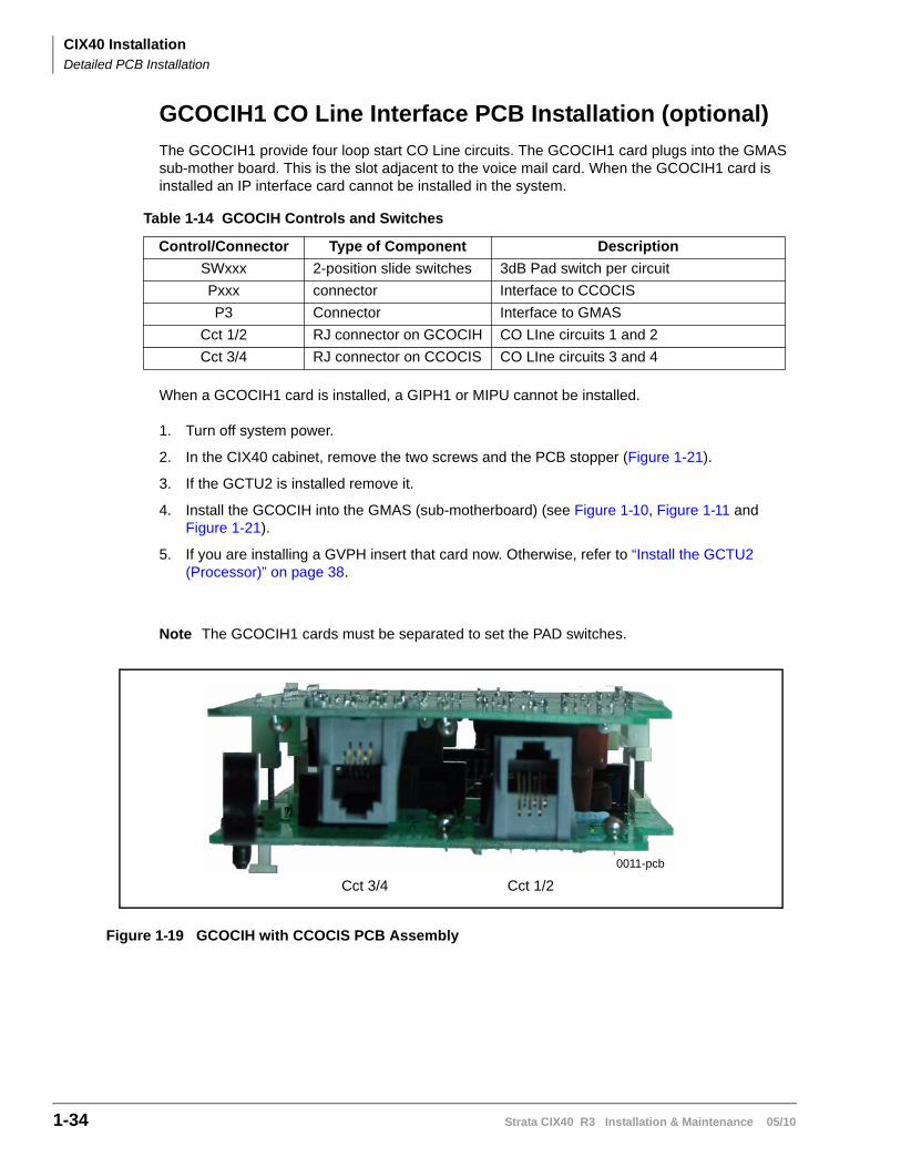
GCOCIH1 CO Line Interface PCB Installation (optional)
The GCOCIH1 provide four loop start CO Line circuits. The GCOCIH1 card plugs into the GMAS sub-mother board. This is the slot adjacent to the voice mail card. When the GCOCIH1 card is installed an IP interface card cannot be installed in the system.
When a GCOCIH1 card is installed, a GIPH1 or MIPU cannot be installed.
1. Turn off system power.
2. In the CIX40 cabinet, remove the two screws and the PCB stopper (Figure 1-21).
3. If the GCTU2 is installed remove it.
4. Install the GCOCIH into the GMAS (sub-motherboard) (see Figure 1-10, Figure 1-11 and Figure 1-21).
5. If you are installing a GVPH insert that card now. Otherwise, refer to “Install the GCTU2 (Processor)” on page 38.
Note The GCOCIH1 cards must be separated to set the PAD switches.
Figure 1-19 GCOCIH with CCOCIS PCB Assembly
Table 1-14 GCOCIH Controls and Switches
Control/Connector Type of Component Description
SWxxx 2-position slide switches 3dB Pad switch per circuit
Pxxx connector Interface to CCOCIS
P3 Connector Interface to GMAS
Cct 1/2 RJ connector on GCOCIH CO LIne circuits 1 and 2
Cct 3/4 RJ connector on CCOCIS CO LIne circuits 3 and 4
0011-pcb
Cct 3/4 Cct 1/2
CIX40 InstallationDetailed PCB Installation
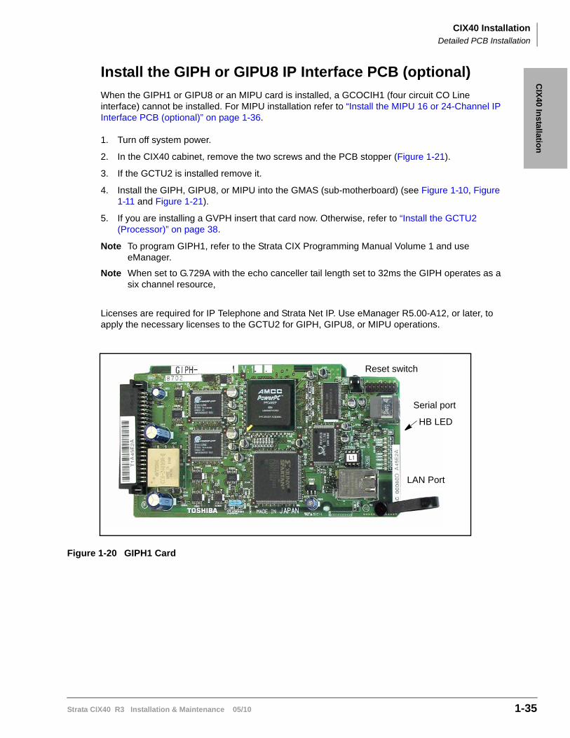
Strata CIX40 R3 Installation & Maintenance 05/10 1-35
CIX
40 In
stallation
Install the GIPH or GIPU8 IP Interface PCB (optional)
When the GIPH1 or GIPU8 or an MIPU card is installed, a GCOCIH1 (four circuit CO Line interface) cannot be installed. For MIPU installation refer to “Install the MIPU 16 or 24-Channel IP Interface PCB (optional)” on page 1-36.
1. Turn off system power.
2. In the CIX40 cabinet, remove the two screws and the PCB stopper (Figure 1-21).
3. If the GCTU2 is installed remove it.
4. Install the GIPH, GIPU8, or MIPU into the GMAS (sub-motherboard) (see Figure 1-10, Figure 1-11 and Figure 1-21).
5. If you are installing a GVPH insert that card now. Otherwise, refer to “Install the GCTU2 (Processor)” on page 38.
Note To program GIPH1, refer to the Strata CIX Programming Manual Volume 1 and use eManager.
Note When set to G.729A with the echo canceller tail length set to 32ms the GIPH operates as a six channel resource,
Licenses are required for IP Telephone and Strata Net IP. Use eManager R5.00-A12, or later, to apply the necessary licenses to the GCTU2 for GIPH, GIPU8, or MIPU operations.
Figure 1-20 GIPH1 Card
Reset switch
Serial port
HB LED
LAN Port
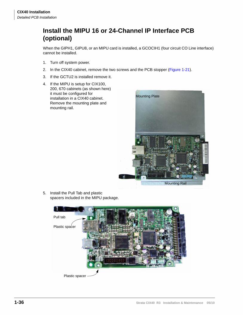
CIX40 InstallationDetailed PCB Installation
1-36 Strata CIX40 R3 Installation & Maintenance 05/10
Install the MIPU 16 or 24-Channel IP Interface PCB (optional)
When the GIPH1, GIPU8, or an MIPU card is installed, a GCOCIH1 (four circuit CO Line interface) cannot be installed.
1. Turn off system power.
2. In the CIX40 cabinet, remove the two screws and the PCB stopper (Figure 1-21).
3. If the GCTU2 is installed remove it.
4. If the MIPU is setup for CIX100, 200, 670 cabinets (as shown here) it must be configured for installation in a CIX40 cabinet. Remove the mounting plate and mounting rail.
5. Install the Pull Tab and plastic spacers included in the MIPU package.
Mounting Plate
Mounting Rail
Pull tab
Plastic spacer
Plastic spacer
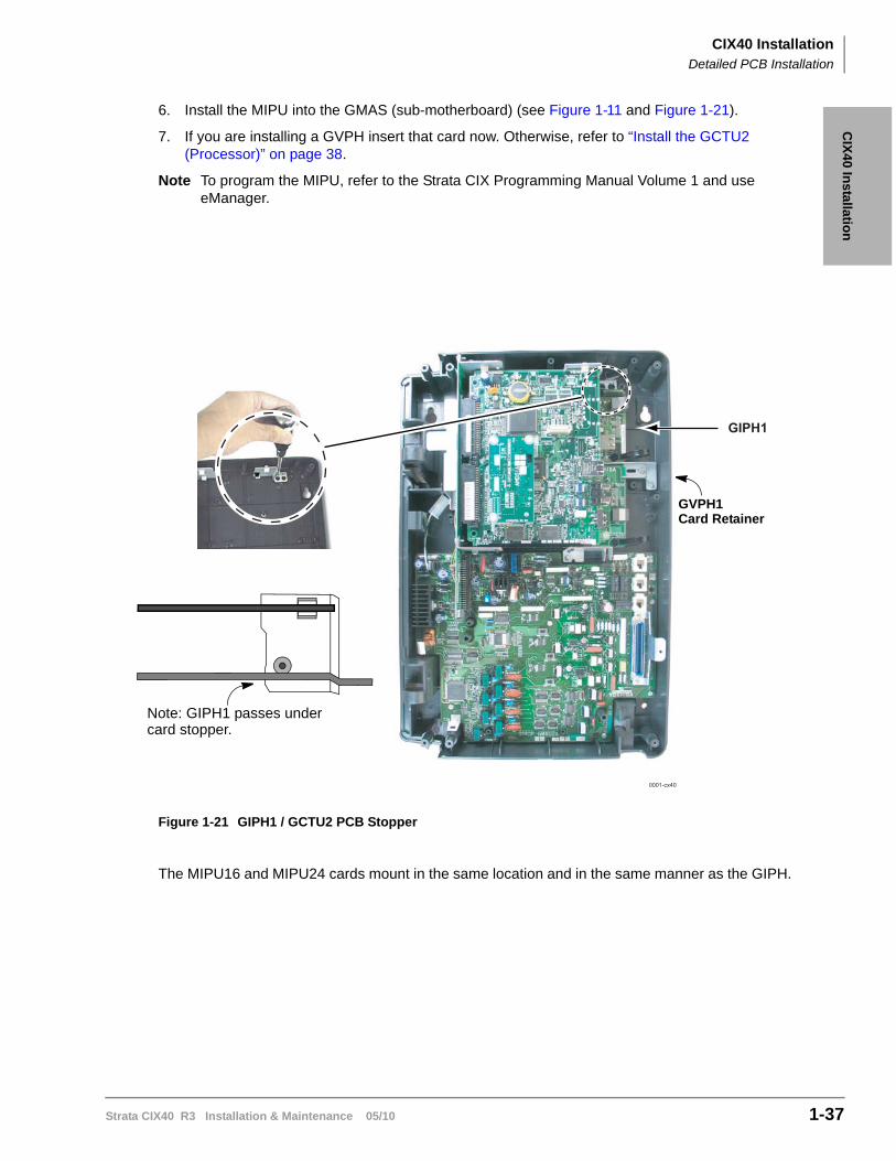
CIX40 InstallationDetailed PCB Installation
Strata CIX40 R3 Installation & Maintenance 05/10 1-37
CIX
40 In
stallation
6. Install the MIPU into the GMAS (sub-motherboard) (see Figure 1-11 and Figure 1-21).
7. If you are installing a GVPH insert that card now. Otherwise, refer to “Install the GCTU2 (Processor)” on page 38.
Note To program the MIPU, refer to the Strata CIX Programming Manual Volume 1 and use eManager.
Figure 1-21 GIPH1 / GCTU2 PCB Stopper
The MIPU16 and MIPU24 cards mount in the same location and in the same manner as the GIPH.
0001-cx40
GIPH1
Note: GIPH1 passes undercard stopper.
GVPH1Card Retainer
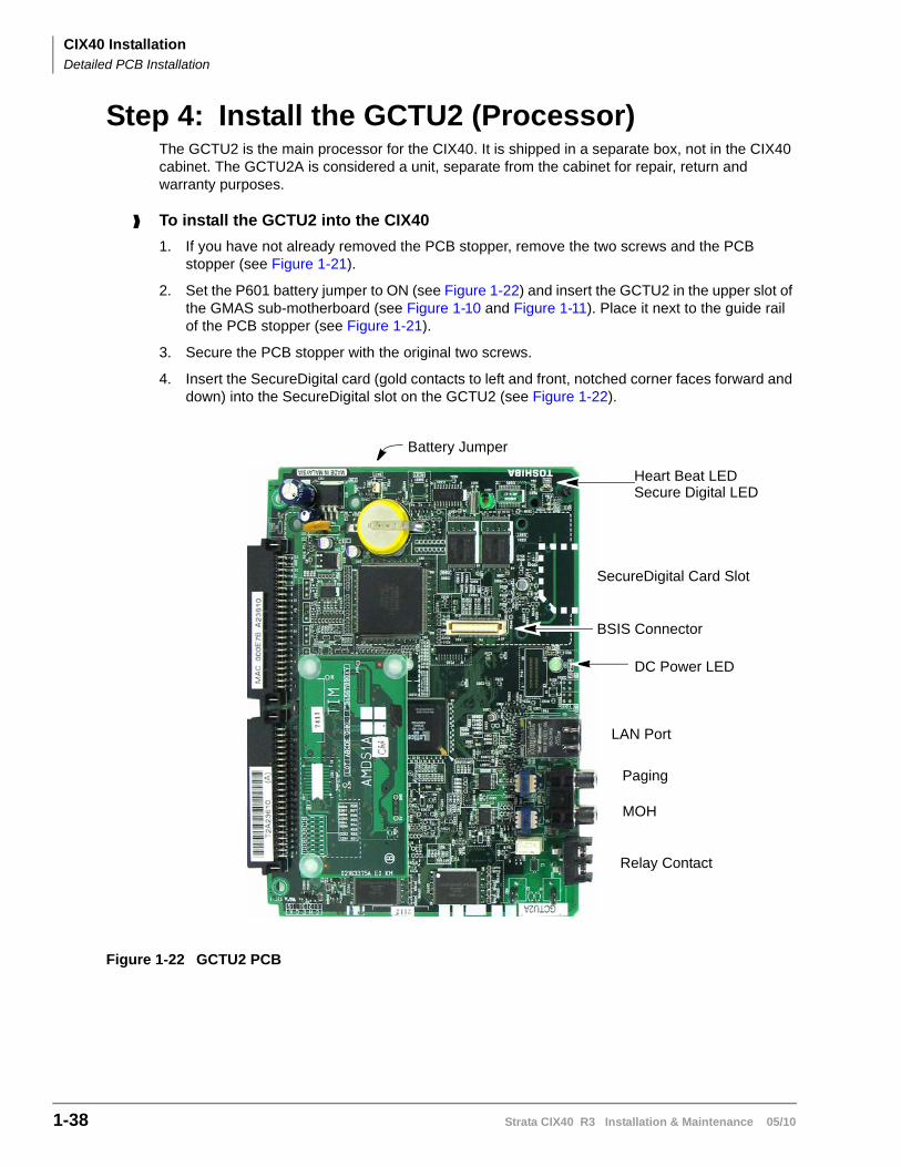
CIX40 InstallationDetailed PCB Installation
1-38 Strata CIX40 R3 Installation & Maintenance 05/10
Step 4: Install the GCTU2 (Processor)The GCTU2 is the main processor for the CIX40. It is shipped in a separate box, not in the CIX40 cabinet. The GCTU2A is considered a unit, separate from the cabinet for repair, return and warranty purposes.
To install the GCTU2 into the CIX40
1. If you have not already removed the PCB stopper, remove the two screws and the PCB stopper (see Figure 1-21).
2. Set the P601 battery jumper to ON (see Figure 1-22) and insert the GCTU2 in the upper slot of the GMAS sub-motherboard (see Figure 1-10 and Figure 1-11). Place it next to the guide rail of the PCB stopper (see Figure 1-21).
3. Secure the PCB stopper with the original two screws.
4. Insert the SecureDigital card (gold contacts to left and front, notched corner faces forward and down) into the SecureDigital slot on the GCTU2 (see Figure 1-22).
Figure 1-22 GCTU2 PCB
Battery Jumper
SecureDigital Card Slot
LAN Port
MOH
Paging
Relay Contact
Heart Beat LEDSecure Digital LED
DC Power LED
BSIS Connector
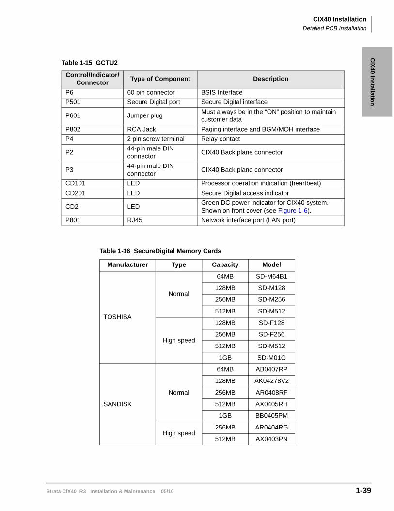
CIX40 InstallationDetailed PCB Installation
Strata CIX40 R3 Installation & Maintenance 05/10 1-39
CIX
40 In
stallation
Table 1-15 GCTU2
Control/Indicator/Connector
Type of Component Description
P6 60 pin connector BSIS Interface
P501 Secure Digital port Secure Digital interface
P601 Jumper plugMust always be in the “ON” position to maintain customer data
P802 RCA Jack Paging interface and BGM/MOH interface
P4 2 pin screw terminal Relay contact
P244-pin male DIN connector
CIX40 Back plane connector
P344-pin male DIN connector
CIX40 Back plane connector
CD101 LED Processor operation indication (heartbeat)
CD201 LED Secure Digital access indicator
CD2 LEDGreen DC power indicator for CIX40 system. Shown on front cover (see Figure 1-6).
P801 RJ45 Network interface port (LAN port)
Table 1-16 SecureDigital Memory Cards
Manufacturer Type Capacity Model
TOSHIBA
Normal
64MB SD-M64B1
128MB SD-M128
256MB SD-M256
512MB SD-M512
High speed
128MB SD-F128
256MB SD-F256
512MB SD-M512
1GB SD-M01G
SANDISK
Normal
64MB AB0407RP
128MB AK04278V2
256MB AR0408RF
512MB AX0405RH
1GB BB0405PM
High speed256MB AR0404RG
512MB AX0403PN
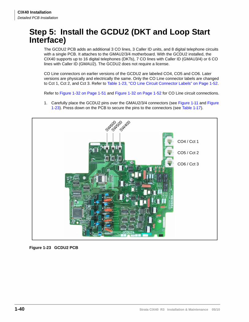
CIX40 InstallationDetailed PCB Installation
1-40 Strata CIX40 R3 Installation & Maintenance 05/10
Step 5: Install the GCDU2 (DKT and Loop Start Interface)
The GCDU2 PCB adds an additional 3 CO lines, 3 Caller ID units, and 8 digital telephone circuits with a single PCB. It attaches to the GMAU2/3/4 motherboard. With the GCDU2 installed, the CIX40 supports up to 16 digital telephones (DKTs), 7 CO lines with Caller ID (GMAU3/4) or 6 CO lines with Caller ID (GMAU2). The GCDU2 does not require a license.
CO Line connectors on earlier versions of the GCDU2 are labeled CO4, CO5 and CO6. Later versions are physically and electrically the same. Only the CO Line connector labels are changed to Cct 1, Cct 2, and Cct 3. Refer to Table 1-23, “CO Line Circuit Connector Labels” on Page 1-52.
Refer to Figure 1-32 on Page 1-51 and Figure 1-32 on Page 1-52 for CO Line circuit connections.
1. Carefully place the GCDU2 pins over the GMAU2/3/4 connectors (see Figure 1-11 and Figure 1-23). Press down on the PCB to secure the pins to the connectors (see Table 1-17).
Figure 1-23 GCDU2 PCB
CO4 / Cct 1
CO5 / Cct 2
CO6 / Cct 3
SW60
0
SW50
0
SW40
0
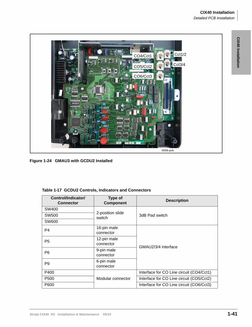
CIX40 InstallationDetailed PCB Installation
Strata CIX40 R3 Installation & Maintenance 05/10 1-41
CIX
40 In
stallation
Figure 1-24 GMAU3 with GCDU2 Installed
Table 1-17 GCDU2 Controls, Indicators and Connectors
Control/Indicator/Connector
Type of Component
Description
SW4002-position slide switch
3dB Pad switchSW500
SW600
P416-pin male connector
GMAU2/3/4 interfaceP5
12-pin male connector
P69-pin male connector
P96-pin male connector
P400
Modular connector
Interface for CO Line circuit (CO4/Cct1)
P500 Interface for CO Line circuit (CO5/Cct2)
P600 Interface for CO Line circuit (CO6/Cct3)
0006-pcb
CO6/Cct3
CO5/Cct2
CO4/Cct1 Cct1/2
Cct3/4
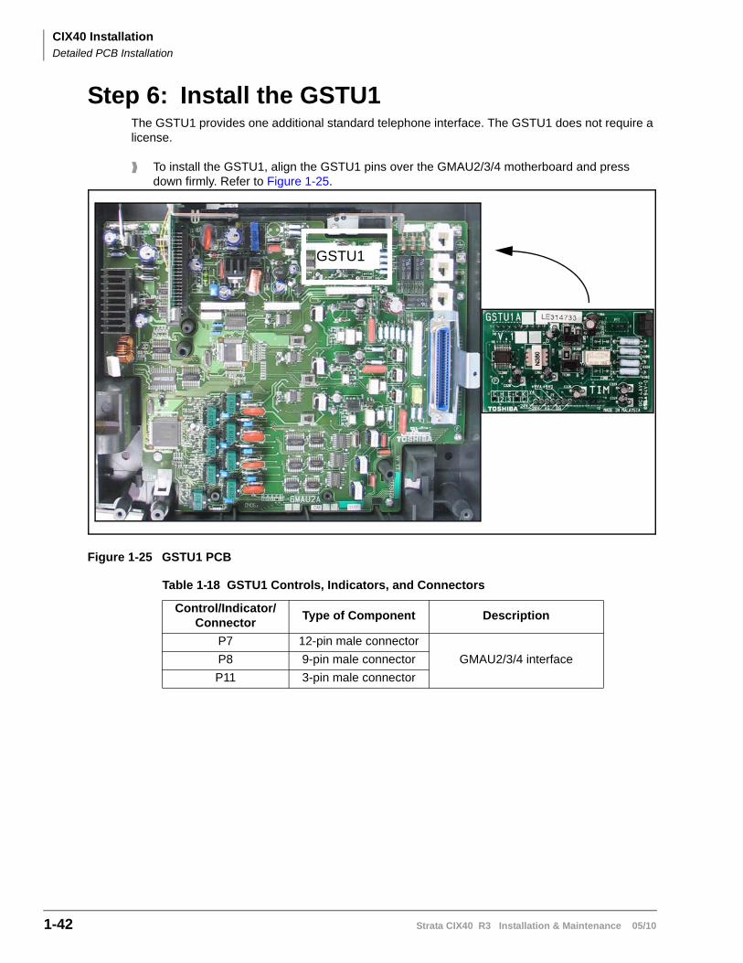
CIX40 InstallationDetailed PCB Installation
1-42 Strata CIX40 R3 Installation & Maintenance 05/10
Step 6: Install the GSTU1The GSTU1 provides one additional standard telephone interface. The GSTU1 does not require a license.
To install the GSTU1, align the GSTU1 pins over the GMAU2/3/4 motherboard and press down firmly. Refer to Figure 1-25.
Figure 1-25 GSTU1 PCB
Table 1-18 GSTU1 Controls, Indicators, and Connectors
Control/Indicator/Connector
Type of Component Description
P7 12-pin male connector
GMAU2/3/4 interfaceP8 9-pin male connector
P11 3-pin male connector
GSTU1
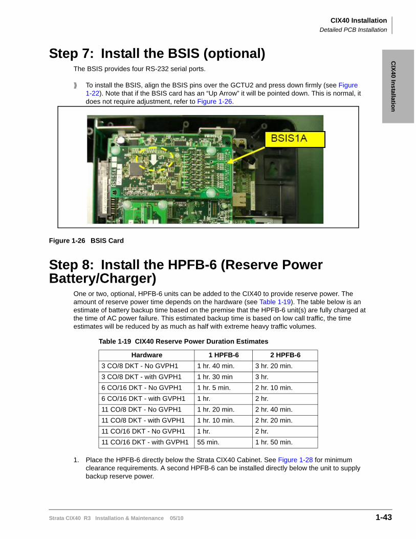
CIX40 InstallationDetailed PCB Installation
Strata CIX40 R3 Installation & Maintenance 05/10 1-43
CIX
40 In
stallation
Step 7: Install the BSIS (optional)The BSIS provides four RS-232 serial ports.
To install the BSIS, align the BSIS pins over the GCTU2 and press down firmly (see Figure 1-22). Note that if the BSIS card has an “Up Arrow” it will be pointed down. This is normal, it does not require adjustment, refer to Figure 1-26.
Figure 1-26 BSIS Card
Step 8: Install the HPFB-6 (Reserve Power Battery/Charger)
One or two, optional, HPFB-6 units can be added to the CIX40 to provide reserve power. The amount of reserve power time depends on the hardware (see Table 1-19). The table below is an estimate of battery backup time based on the premise that the HPFB-6 unit(s) are fully charged at the time of AC power failure. This estimated backup time is based on low call traffic, the time estimates will be reduced by as much as half with extreme heavy traffic volumes.
1. Place the HPFB-6 directly below the Strata CIX40 Cabinet. See Figure 1-28 for minimum clearance requirements. A second HPFB-6 can be installed directly below the unit to supply backup reserve power.
Table 1-19 CIX40 Reserve Power Duration Estimates
Hardware 1 HPFB-6 2 HPFB-6
3 CO/8 DKT - No GVPH1 1 hr. 40 min. 3 hr. 20 min.
3 CO/8 DKT - with GVPH1 1 hr. 30 min 3 hr.
6 CO/16 DKT - No GVPH1 1 hr. 5 min. 2 hr. 10 min.
6 CO/16 DKT - with GVPH1 1 hr. 2 hr.
11 CO/8 DKT - No GVPH1 1 hr. 20 min. 2 hr. 40 min.
11 CO/8 DKT - with GVPH1 1 hr. 10 min. 2 hr. 20 min.
11 CO/16 DKT - No GVPH1 1 hr. 2 hr.
11 CO/16 DKT - with GVPH1 55 min. 1 hr. 50 min.
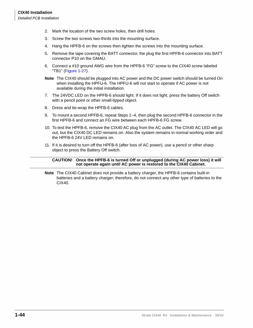
CIX40 InstallationDetailed PCB Installation
1-44 Strata CIX40 R3 Installation & Maintenance 05/10
2. Mark the location of the two screw holes, then drill holes.
3. Screw the two screws two-thirds into the mounting surface.
4. Hang the HPFB-6 on the screws then tighten the screws into the mounting surface.
5. Remove the tape covering the BATT connector, the plug the first HPFB-6 connector into BATT connector P10 on the GMAU.
6. Connect a #10 ground AWG wire from the HPFB-6 “FG” screw to the CIX40 screw labeled “TB1” (Figure 1-27).
Note The CIX40 should be plugged into AC power and the DC power switch should be turned On when installing the HPFU-6. The HPFU-6 will not start to operate if AC power is not available during the initial installation.
7. The 24VDC LED on the HPFB-6 should light. If it does not light, press the battery Off switch with a pencil point or other small-tipped object.
8. Dress and tie-wrap the HPFB-6 cables.
9. To mount a second HPFB-6, repeat Steps 1~4, then plug the second HPFB-6 connector in the first HPFB-6 and connect an FG wire between each HPFB-6 FG screw.
10. To test the HPFB-6, remove the CIX40 AC plug from the AC outlet. The CIX40 AC LED will go out, but the CIX40 DC LED remains on. Also the system remains in normal working order and the HPFB-6 24V LED remains on.
11. If it is desired to turn off the HPFB-6 (after loss of AC power), use a pencil or other sharp object to press the Battery Off switch.
CAUTION! Once the HPFB-6 is turned Off or unplugged (during AC power loss) it will not operate again until AC power is restored to the CIX40 Cabinet.
Note The CIX40 Cabinet does not provide a battery charger, the HPFB-6 contains built-in batteries and a battery charger; therefore, do not connect any other type of batteries to the CIX40.
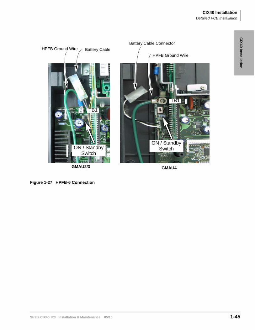
CIX40 InstallationDetailed PCB Installation
Strata CIX40 R3 Installation & Maintenance 05/10 1-45
CIX
40 In
stallation
Figure 1-27 HPFB-6 Connection
GMAU2/3
HPFB Ground Wire
TB1
ON / StandbySwitch
GMAU4
ON / StandbySwitch
Battery Cable
TB1
HPFB Ground Wire
Battery Cable Connector
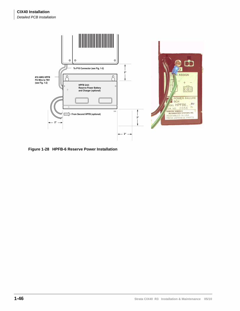
CIX40 InstallationDetailed PCB Installation
1-46 Strata CIX40 R3 Installation & Maintenance 05/10
Figure 1-28 HPFB-6 Reserve Power Installation
2“
From Second HPFB (optional)
To P10 Connector (see Fig. 1-2)
HPFB Unit: Reserve Power Battery and Charger (optional)
#10 AWG HPFB FG Wire to TB1(see Fig. 1-2)
7253
2“
2“
2“
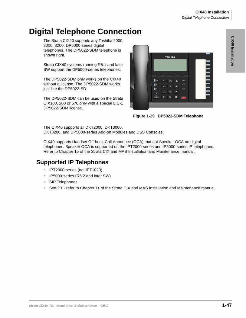
CIX40 InstallationDigital Telephone Connection
Strata CIX40 R3 Installation & Maintenance 05/10 1-47
CIX
40 In
stallation
Digital Telephone ConnectionThe Strata CIX40 supports any Toshiba 2000, 3000, 3200, DP5000-series digital telephones. The DP5022-SDM telephone is shown right.
Strata CIX40 systems running R5.1 and later SW support the DP5000-series telephones.
The DP5022-SDM only works on the CIX40 without a license. The DP5022-SDM works just like the DP5022-SD.
The DP5022-SDM can be used on the Strata CIX100, 200 or 670 only with a special LIC-1 DP5022-SDM license.
The CIX40 supports all DKT2000, DKT3000, DKT3200, and DP5000-series Add-on Modules and DSS Consoles.
CIX40 supports Handset Off-hook Call Announce (OCA), but not Speaker OCA on digital telephones. Speaker OCA is supported on the IPT2000-series and IP5000-series IP telephones. Refer to Chapter 15 of the Strata CIX and MAS Installation and Maintenance manual.
Supported IP Telephones• IPT2000-series (not IPT1020)
• IP5000-series (R5.2 and later SW)
• SIP Telephones
• SoftIPT - refer to Chapter 11 of the Strata CIX and MAS Installation and Maintenance manual.
Figure 1-29 DP5022-SDM Telephone
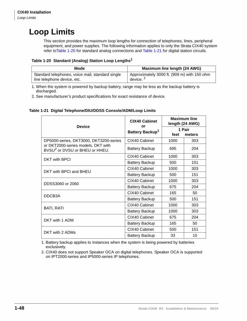
CIX40 InstallationLoop Limits
1-48 Strata CIX40 R3 Installation & Maintenance 05/10
Loop LimitsThis section provides the maximum loop lengths for connection of telephones, lines, peripheral equipment, and power supplies. The following information applies to only the Strata CIX40 system refer toTable 1-20 for standard analog connections and Table 1-21 for digital station circuits.
Table 1-21 Digital Telephone/DIU/DDSS Console/ADM/Loop Limits
Table 1-20 Standard (Analog) Station Loop Lengths1
1. When the system is powered by backup battery, range may be less as the backup battery is discharged.
Mode Maximum line length (24 AWG)
Standard telephones, voice mail, standard single line telephone device, etc.
Approximately 3000 ft. (909 m) with 150 ohm device. 2
2. See manufacturer’s product specifications for exact resistance of device.
DeviceCIX40 Cabinet
or
Battery Backup1
1. Battery backup applies to instances when the system is being powered by batteries exclusively.
Maximum line length (24 AWG)
1 Pair feet meters
DP5000-series, DKT3000, DKT3200-series or DKT2000-series models, DKT with BVSU2 or DVSU or BHEU or HHEU.
2. CIX40 does not support Speaker OCA on digital telephones. Speaker OCA is supported on IPT2000-series and IP5000-series IP telephones.
CIX40 Cabinet 1000 303
Battery Backup 695 204
DKT with BPCICIX40 Cabinet 1000 303
Battery Backup 500 151
DKT with BPCI and BHEUCIX40 Cabinet 1000 303
Battery Backup 500 151
DDSS3060 or 2060CIX40 Cabinet 1000 303
Battery Backup 675 204
DDCB3ACIX40 Cabinet 165 50
Battery Backup 500 151
BATI, RATICIX40 Cabinet 1000 303
Battery Backup 1000 303
DKT with 1 ADMCIX40 Cabinet 675 204
Battery Backup 165 50
DKT with 2 ADMsCIX40 Cabinet 500 151
Battery Backup 33 10
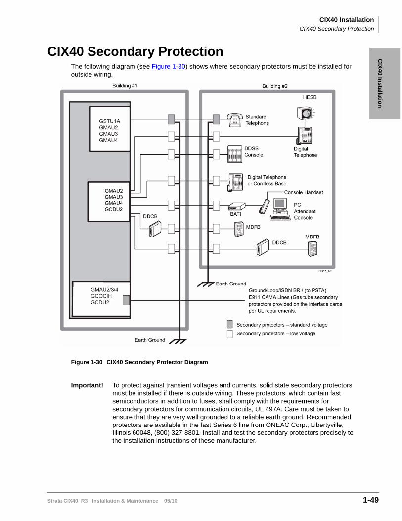
CIX40 InstallationCIX40 Secondary Protection
Strata CIX40 R3 Installation & Maintenance 05/10 1-49
CIX
40 In
stallation
CIX40 Secondary ProtectionThe following diagram (see Figure 1-30) shows where secondary protectors must be installed for outside wiring.
Figure 1-30 CIX40 Secondary Protector Diagram
Important! To protect against transient voltages and currents, solid state secondary protectors must be installed if there is outside wiring. These protectors, which contain fast semiconductors in addition to fuses, shall comply with the requirements for secondary protectors for communication circuits, UL 497A. Care must be taken to ensure that they are very well grounded to a reliable earth ground. Recommended protectors are available in the fast Series 6 line from ONEAC Corp., Libertyville, Illinois 60048, (800) 327-8801. Install and test the secondary protectors precisely to the installation instructions of these manufacturer.
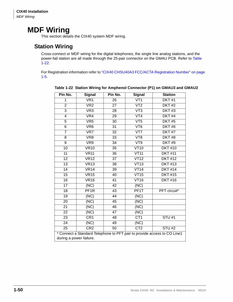
CIX40 InstallationMDF Wiring
1-50 Strata CIX40 R3 Installation & Maintenance 05/10
MDF WiringThis section details the CIX40 system MDF wiring.
Station WiringCross-connect or MDF wiring for the digital telephones, the single line analog stations, and the power-fail station are all made through the 25-pair connector on the GMAU PCB. Refer to Table 1-22.
For Registration information refer to “CIX40 CHSU40A3 FCC/ACTA Registration Number” on page 1-5.
Table 1-22 Station Wiring for Amphenol Connector (P1) on GMAU3 and GMAU2
Pin No. Signal Pin No. Signal Station
1 VR1 26 VT1 DKT #1
2 VR2 27 VT2 DKT #2
3 VR3 28 VT3 DKT #3
4 VR4 29 VT4 DKT #4
5 VR5 30 VT5 DKT #5
6 VR6 31 VT6 DKT #6
7 VR7 32 VT7 DKT #7
8 VR8 33 VT8 DKT #8
9 VR9 34 VT9 DKT #9
10 VR10 35 VT10 DKT #10
11 VR11 36 VT11 DKT #11
12 VR12 37 VT12 DKT #12
13 VR13 38 VT13 DKT #13
14 VR14 39 VT14 DKT #14
15 VR15 40 VT15 DKT #15
16 VR16 41 VT16 DKT #16
17 (NC) 42 (NC)
18 PF1R 43 PF1T PFT circuit*
19 (NC) 44 (NC)
20 (NC) 45 (NC)
21 (NC) 46 (NC)
22 (NC) 47 (NC)
23 CR1 48 CT1 STU #1
24 (NC) 49 (NC)
25 CR2 50 CT2 STU #2
* Connect a Standard Telephone to PFT pair to provide access to CO Line1 during a power failure.
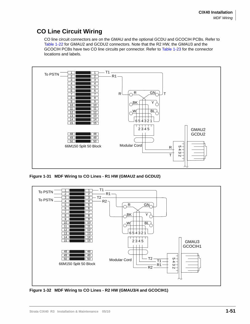
CIX40 InstallationMDF Wiring
Strata CIX40 R3 Installation & Maintenance 05/10 1-51
CO Line Circuit WiringCO line circuit connectors are on the GMAU and the optional GCDU and GCOCIH PCBs. Refer to Table 1-22 for GMAU2 and GCDU2 connectors. Note that the R2 HW, the GMAU3 and the GCOCIH PCBs have two CO line circuits per connector. Refer to Table 1-23 for the connector locations and labels.
Figure 1-31 MDF Wiring to CO Lines - R1 HW (GMAU2 and GCDU2)
Figure 1-32 MDF Wiring to CO Lines - R2 HW (GMAU3/4 and GCOCIH1)
R GN
BK Y
W BL
2
2 3 4 5
13456
54
32
GMAU2GCDU2
TR
T
R
123456789
101112131415
484950
123456789101112131415
484950
66M150 Split 50 Block Modular Cord
To PSTNT1
R1
R GN
BK Y
W BL
2
2 3 4 5
13456
54
32
GMAU3GCOCIH1
123456789101112131415
484950
123456789
101112131415
484950
66M150 Split 50 BlockModular Cord
To PSTNT1
R1T2
R2
T1R1
T2
R2
To PSTN
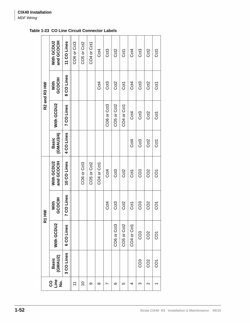
CIX40 InstallationMDF Wiring
1-52 Strata CIX40 R3 Installation & Maintenance 05/10
Table 1-23 CO Line Circuit Connector Labels
CO
L
ine
No
.
R1
HW
R2
and
R3
HW
Ba
sic
(GM
AU
2)
Wit
h G
CD
U2
Wit
h
GC
OC
IHW
ith
GC
DU
2 a
nd
GC
OC
IHB
asic
(GM
AU
3/4
)W
ith
GC
DU
2W
ith
G
CO
CIH
Wit
h G
CD
U2
an
d G
CO
CIH
3 C
O L
ine
s6
CO
Lin
es
7 C
O L
ines
10
CO
Lin
es4
CO
Lin
es7
CO
Lin
es
8 C
O L
ine
s11
CO
Lin
es
11C
O6
or
Cct
3
10
CO
6 o
r C
ct3
CO
5 o
r C
ct2
9C
O5
or
Cct
2C
O4
or
Cct
1
8C
O4
or C
ct1
Cct
4C
ct4
7C
ct4
Cct
4C
O6
or C
ct3
Cct
3C
ct3
6C
O6
or C
ct3
Cct
3C
ct3
CO
5 or
Cct
2C
ct2
Cct
2
5C
O5
or C
ct2
Cct
2C
ct2
CO
4 or
Cct
1C
ct1
Cct
1
4C
O4
or C
ct1
Cct
1C
ct1
Cct
4C
ct4
Cct
4C
ct4
3C
O3
CO
3C
O3
CO
3C
ct3
Cct
3C
ct3
Cct
3
2C
O2
CO
2C
O2
CO
2C
ct2
Cct
2C
ct2
Cct
2
1C
O1
CO
1C
O1
CO
1C
ct1
Cct
1C
ct1
Cct
1
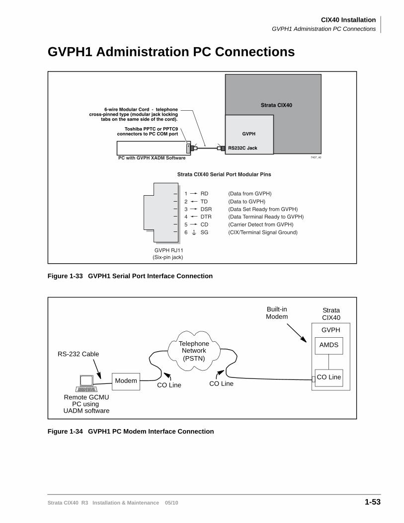
CIX40 InstallationGVPH1 Administration PC Connections
Strata CIX40 R3 Installation & Maintenance 05/10 1-53
GVPH1 Administration PC Connections
Figure 1-33 GVPH1 Serial Port Interface Connection
Figure 1-34 GVPH1 PC Modem Interface Connection
GVPH
Strata CIX40
RS232C Jack
6-wire Modular Cord - telephone cross-pinned type (modular jack locking
tabs on the same side of the cord).
Toshiba PPTC or PPTC9 connectors to PC COM port
7407_40
Strata CIX40 Serial Port Modular Pins
GVPH RJ11(Six-pin jack)
TD
RD
DTRDSR
SG
CD
(Data to GVPH)
(Data from GVPH)
(Data Terminal Ready to GVPH)(Data Set Ready from GVPH)
(CIX/Terminal Signal Ground)
(Carrier Detect from GVPH)
2
1
43
6
5
PC with GVPH XADM Software
Remote GCMUPC using
UADM software
RS-232 Cable
ModemCO Line
Built-in
TelephoneNetwork(PSTN)
StrataCIX40
CO LineCO Line
Modem
AMDS
GVPH

This page is intentionally left blank.
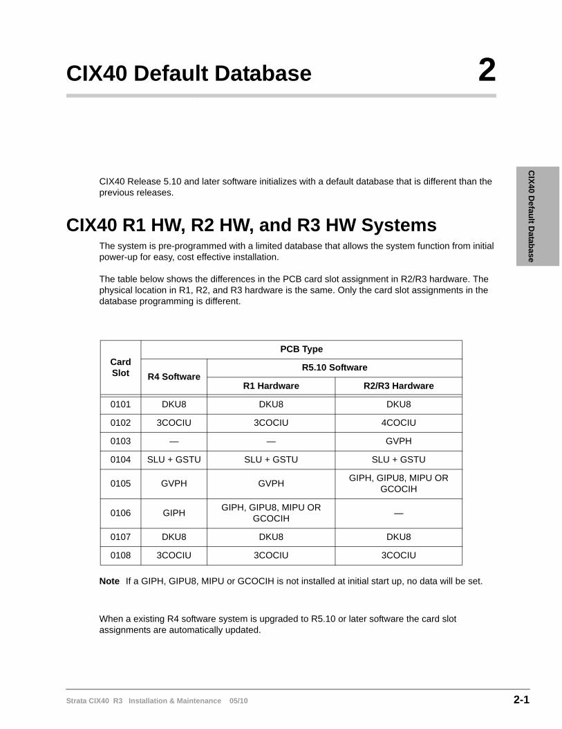
Strata CIX40 R3 Installation & Maintenance 05/10 2-1
CIX
40 Defau
lt Datab
ase
CIX40 Default Database 2
CIX40 Release 5.10 and later software initializes with a default database that is different than the previous releases.
CIX40 R1 HW, R2 HW, and R3 HW SystemsThe system is pre-programmed with a limited database that allows the system function from initial power-up for easy, cost effective installation.
The table below shows the differences in the PCB card slot assignment in R2/R3 hardware. The physical location in R1, R2, and R3 hardware is the same. Only the card slot assignments in the database programming is different.
Note If a GIPH, GIPU8, MIPU or GCOCIH is not installed at initial start up, no data will be set.
When a existing R4 software system is upgraded to R5.10 or later software the card slot assignments are automatically updated.
Card Slot
PCB Type
R4 SoftwareR5.10 Software
R1 Hardware R2/R3 Hardware
0101 DKU8 DKU8 DKU8
0102 3COCIU 3COCIU 4COCIU
0103 — — GVPH
0104 SLU + GSTU SLU + GSTU SLU + GSTU
0105 GVPH GVPHGIPH, GIPU8, MIPU OR
GCOCIH
0106 GIPHGIPH, GIPU8, MIPU OR
GCOCIH—
0107 DKU8 DKU8 DKU8
0108 3COCIU 3COCIU 3COCIU
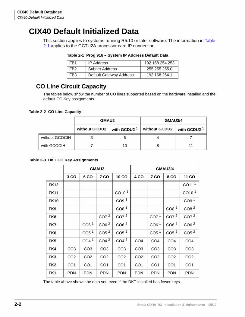
CIX40 Default DatabaseCIX40 Default Initialized Data
2-2 Strata CIX40 R3 Installation & Maintenance 05/10
CIX40 Default Initialized DataThis section applies to systems running R5.10 or later software. The information in Table 2-1 applies to the GCTU2A processor card IP connection.
CO Line Circuit CapacityThe tables below show the number of CO lines supported based on the hardware installed and the default CO Key assignments.
Table 2-2 CO Line Capacity
Table 2-3 DKT CO Key Assignments
The table above shows the data set, even if the DKT installed has fewer keys.
Table 2-1 Prog 916 – System IP Address Default Data
FB1 IP Address 192.168.254.253
FB2 Subnet Address 255.255.255.0
FB3 Default Gateway Address 192.168.254.1
GMAU2 GMAU3/4
without GCDU2 with GCDU2 1 without GCDU2 with GCDU2 1
without GCOCIH 3 6 4 7
with GCOCIH 7 10 8 11
GMAU2 GMAU3/4
3 CO 6 CO 7 CO 10 CO 4 CO 7 CO 8 CO 11 CO
FK12 CO11 1
FK11 CO10 1 CO10 1
FK10 CO9 1 CO9 1
FK9 CO8 1 CO8 2 CO8 2
FK8 CO7 2 CO7 2 CO7 1 CO7 2 CO7 2
FK7 CO6 1 CO6 2 CO6 2 CO6 1 CO6 2 CO6 2
FK6 CO5 1 CO5 2 CO5 2 CO5 1 CO5 2 CO5 2
FK5 CO4 1 CO4 2 CO4 2 CO4 CO4 CO4 CO4
FK4 CO3 CO3 CO3 CO3 CO3 CO3 CO3 CO3
FK3 CO2 CO2 CO2 CO2 CO2 CO2 CO2 CO2
FK2 CO1 CO1 CO1 CO1 CO1 CO1 CO1 CO1
FK1 PDN PDN PDN PDN PDN PDN PDN PDN
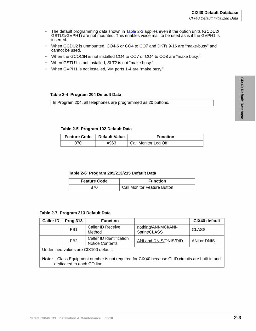
CIX
40 Defau
lt Datab
aseCIX40 Default Database
CIX40 Default Initialized Data
Strata CIX40 R3 Installation & Maintenance 05/10 2-3
• The default programming data shown in Table 2-3 applies even if the option units (GCDU2/GSTU1/GVPH1) are not mounted. This enables voice mail to be used as is if the GVPH1 is inserted.
• When GCDU2 is unmounted, CO4-6 or CO4 to CO7 and DKTs 9-16 are “make-busy” and cannot be used.
• When the GCOCIH is not installed CO4 to CO7 or CO4 to CO8 are “make busy.”
• When GSTU1 is not installed, SLT2 is not “make busy.”
• When GVPH1 is not installed, VM ports 1-4 are “make busy.”
Table 2-4 Program 204 Default Data
In Program 204, all telephones are programmed as 20 buttons.
Table 2-5 Program 102 Default Data
Feature Code Default Value Function
870 #963 Call Monitor Log Off
Table 2-6 Program 205/213/215 Default Data
Feature Code Function
870 Call Monitor Feature Button
Table 2-7 Program 313 Default Data
Caller ID Prog 313 Function CIX40 default
FB1Caller ID Receive Method
nothing/ANI-MCI/ANI-Sprint/CLASS
CLASS
FB2Caller ID Identification Notice Contents
ANI and DNIS/DNIS/DID ANI or DNIS
Underlined values are CIX100 default.
Note: Class Equipment number is not required for CIX40 because CLID circuits are built-in and dedicated to each CO line.
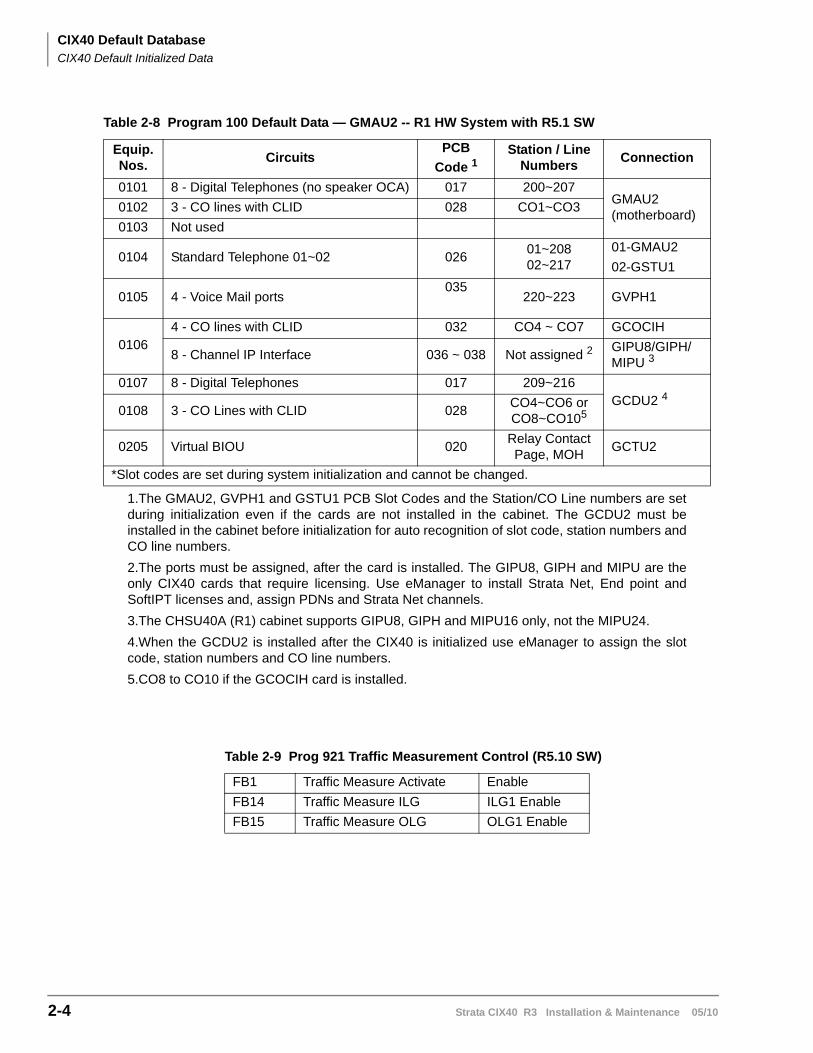
CIX40 Default DatabaseCIX40 Default Initialized Data
2-4 Strata CIX40 R3 Installation & Maintenance 05/10
Table 2-8 Program 100 Default Data — GMAU2 -- R1 HW System with R5.1 SW
Equip.Nos.
CircuitsPCB
Code 1
1.The GMAU2, GVPH1 and GSTU1 PCB Slot Codes and the Station/CO Line numbers are setduring initialization even if the cards are not installed in the cabinet. The GCDU2 must beinstalled in the cabinet before initialization for auto recognition of slot code, station numbers andCO line numbers.
Station / Line Numbers
Connection
0101 8 - Digital Telephones (no speaker OCA) 017 200~207GMAU2 (motherboard)
0102 3 - CO lines with CLID 028 CO1~CO3
0103 Not used
0104 Standard Telephone 01~02 02601~20802~217
01-GMAU2
02-GSTU1
0105 4 - Voice Mail ports035
220~223 GVPH1
01064 - CO lines with CLID 032 CO4 ~ CO7 GCOCIH
8 - Channel IP Interface 036 ~ 038 Not assigned 2
2.The ports must be assigned, after the card is installed. The GIPU8, GIPH and MIPU are theonly CIX40 cards that require licensing. Use eManager to install Strata Net, End point andSoftIPT licenses and, assign PDNs and Strata Net channels.
GIPU8/GIPH/MIPU 3
3.The CHSU40A (R1) cabinet supports GIPU8, GIPH and MIPU16 only, not the MIPU24.
0107 8 - Digital Telephones 017 209~216GCDU2 4
4.When the GCDU2 is installed after the CIX40 is initialized use eManager to assign the slotcode, station numbers and CO line numbers.
0108 3 - CO Lines with CLID 028CO4~CO6 or CO8~CO105
5.CO8 to CO10 if the GCOCIH card is installed.
0205 Virtual BIOU 020Relay Contact Page, MOH
GCTU2
*Slot codes are set during system initialization and cannot be changed.
Table 2-9 Prog 921 Traffic Measurement Control (R5.10 SW)
FB1 Traffic Measure Activate Enable
FB14 Traffic Measure ILG ILG1 Enable
FB15 Traffic Measure OLG OLG1 Enable
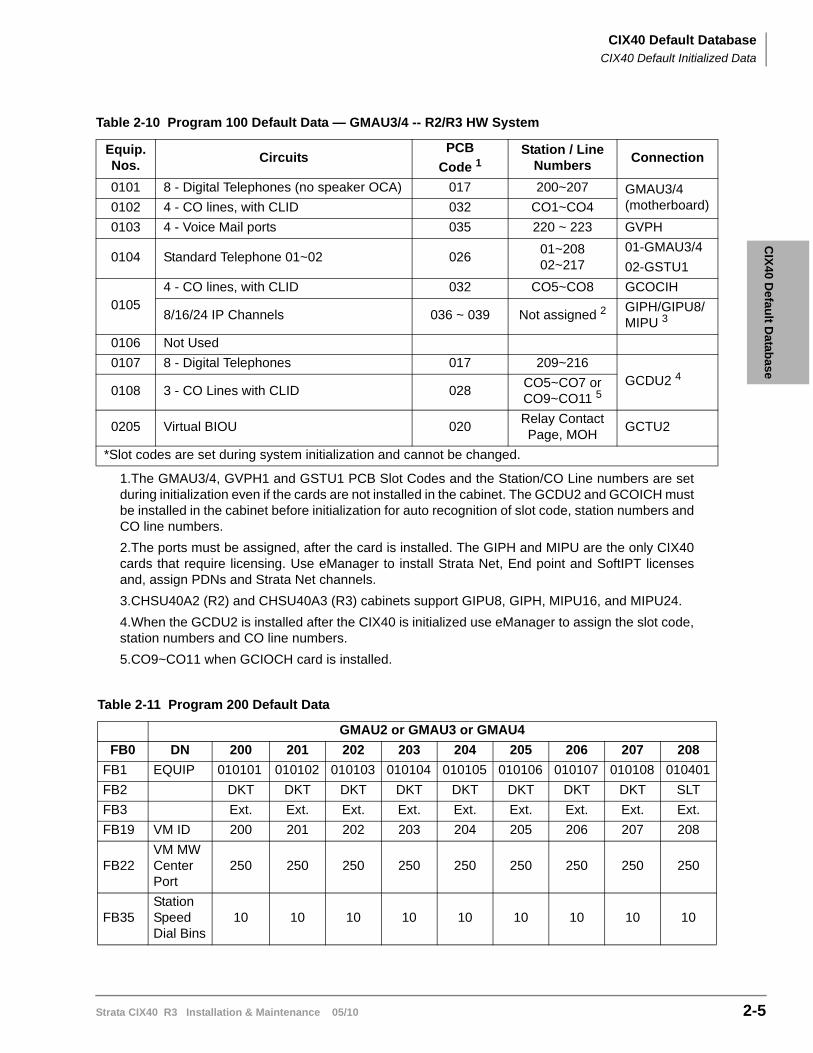
CIX
40 Defau
lt Datab
aseCIX40 Default Database
CIX40 Default Initialized Data
Strata CIX40 R3 Installation & Maintenance 05/10 2-5
Table 2-10 Program 100 Default Data — GMAU3/4 -- R2/R3 HW System
Equip.Nos.
CircuitsPCB
Code 1
1.The GMAU3/4, GVPH1 and GSTU1 PCB Slot Codes and the Station/CO Line numbers are setduring initialization even if the cards are not installed in the cabinet. The GCDU2 and GCOICH mustbe installed in the cabinet before initialization for auto recognition of slot code, station numbers andCO line numbers.
Station / Line Numbers
Connection
0101 8 - Digital Telephones (no speaker OCA) 017 200~207 GMAU3/4 (motherboard)0102 4 - CO lines, with CLID 032 CO1~CO4
0103 4 - Voice Mail ports 035 220 ~ 223 GVPH
0104 Standard Telephone 01~02 02601~20802~217
01-GMAU3/4
02-GSTU1
01054 - CO lines, with CLID 032 CO5~CO8 GCOCIH
8/16/24 IP Channels 036 ~ 039 Not assigned 2
2.The ports must be assigned, after the card is installed. The GIPH and MIPU are the only CIX40cards that require licensing. Use eManager to install Strata Net, End point and SoftIPT licensesand, assign PDNs and Strata Net channels.
GIPH/GIPU8/MIPU 3
3.CHSU40A2 (R2) and CHSU40A3 (R3) cabinets support GIPU8, GIPH, MIPU16, and MIPU24.
0106 Not Used
0107 8 - Digital Telephones 017 209~216GCDU2 4
4.When the GCDU2 is installed after the CIX40 is initialized use eManager to assign the slot code,station numbers and CO line numbers.
0108 3 - CO Lines with CLID 028CO5~CO7 or CO9~CO11 5
5.CO9~CO11 when GCIOCH card is installed.
0205 Virtual BIOU 020Relay Contact Page, MOH
GCTU2
*Slot codes are set during system initialization and cannot be changed.
Table 2-11 Program 200 Default Data
GMAU2 or GMAU3 or GMAU4
FB0 DN 200 201 202 203 204 205 206 207 208
FB1 EQUIP 010101 010102 010103 010104 010105 010106 010107 010108 010401
FB2 DKT DKT DKT DKT DKT DKT DKT DKT SLT
FB3 Ext. Ext. Ext. Ext. Ext. Ext. Ext. Ext. Ext.
FB19 VM ID 200 201 202 203 204 205 206 207 208
FB22VM MW Center Port
250 250 250 250 250 250 250 250 250
FB35Station Speed Dial Bins
10 10 10 10 10 10 10 10 10
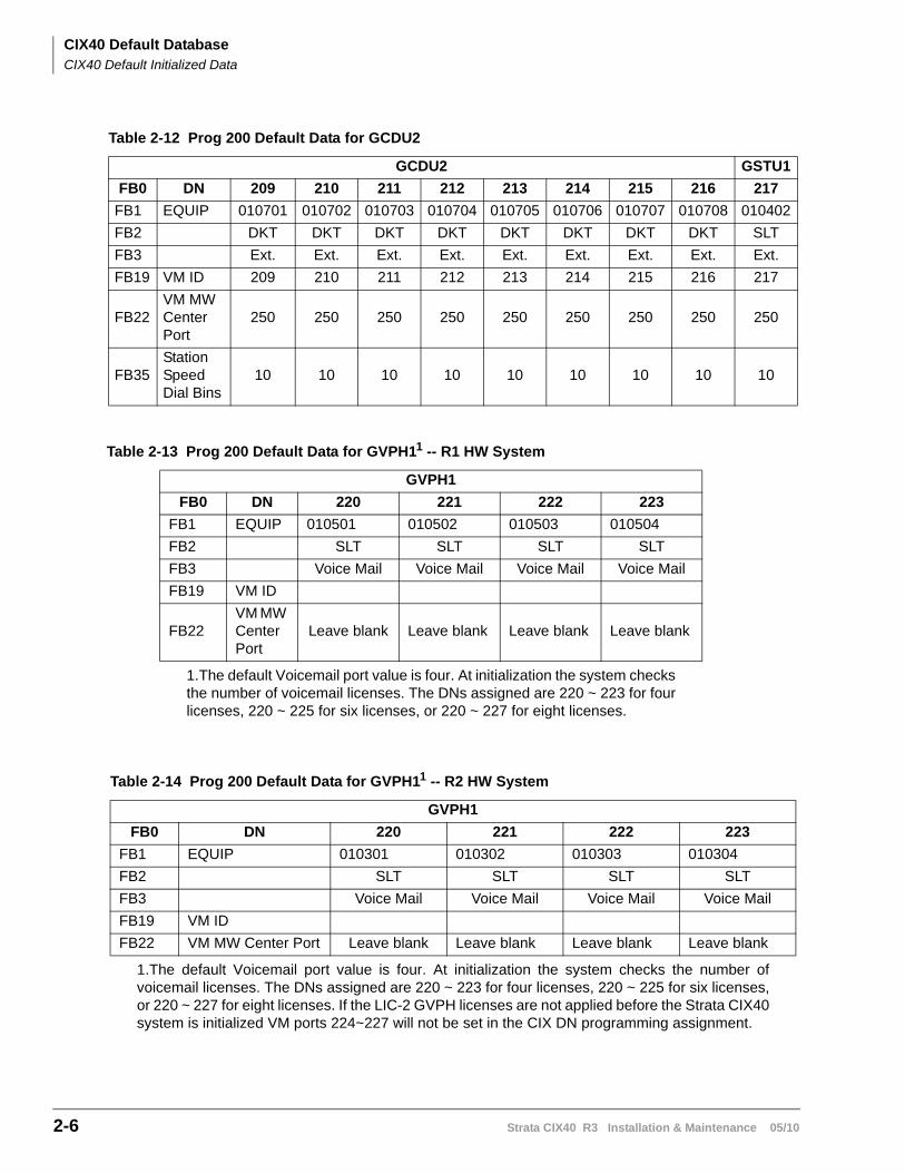
CIX40 Default DatabaseCIX40 Default Initialized Data
2-6 Strata CIX40 R3 Installation & Maintenance 05/10
Table 2-12 Prog 200 Default Data for GCDU2
GCDU2 GSTU1
FB0 DN 209 210 211 212 213 214 215 216 217
FB1 EQUIP 010701 010702 010703 010704 010705 010706 010707 010708 010402
FB2 DKT DKT DKT DKT DKT DKT DKT DKT SLT
FB3 Ext. Ext. Ext. Ext. Ext. Ext. Ext. Ext. Ext.
FB19 VM ID 209 210 211 212 213 214 215 216 217
FB22VM MW Center Port
250 250 250 250 250 250 250 250 250
FB35Station Speed Dial Bins
10 10 10 10 10 10 10 10 10
Table 2-13 Prog 200 Default Data for GVPH11 -- R1 HW System
1.The default Voicemail port value is four. At initialization the system checksthe number of voicemail licenses. The DNs assigned are 220 ~ 223 for fourlicenses, 220 ~ 225 for six licenses, or 220 ~ 227 for eight licenses.
GVPH1
FB0 DN 220 221 222 223
FB1 EQUIP 010501 010502 010503 010504
FB2 SLT SLT SLT SLT
FB3 Voice Mail Voice Mail Voice Mail Voice Mail
FB19 VM ID
FB22VM MW Center Port
Leave blank Leave blank Leave blank Leave blank
Table 2-14 Prog 200 Default Data for GVPH11 -- R2 HW System
1.The default Voicemail port value is four. At initialization the system checks the number ofvoicemail licenses. The DNs assigned are 220 ~ 223 for four licenses, 220 ~ 225 for six licenses,or 220 ~ 227 for eight licenses. If the LIC-2 GVPH licenses are not applied before the Strata CIX40system is initialized VM ports 224~227 will not be set in the CIX DN programming assignment.
GVPH1
FB0 DN 220 221 222 223
FB1 EQUIP 010301 010302 010303 010304
FB2 SLT SLT SLT SLT
FB3 Voice Mail Voice Mail Voice Mail Voice Mail
FB19 VM ID
FB22 VM MW Center Port Leave blank Leave blank Leave blank Leave blank
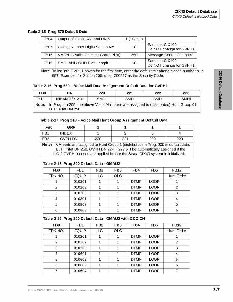
CIX
40 Defau
lt Datab
aseCIX40 Default Database
CIX40 Default Initialized Data
Strata CIX40 R3 Installation & Maintenance 05/10 2-7
Note To log into GVPH1 boxes for the first time, enter the default telephone station number plus 997. Example: for Station 200, enter 200997 as the Security Code.
Table 2-15 Prog 579 Default Data
FB04 Output of Class, ANI and DNIS 1 (Enable)
FB05 Calling Number Digits Sent to VM 10Same as CIX100Do NOT change for GVPH1
FB16 VMDN (Distributed Hunt Group Pilot) 250 Message Center Call-back
FB19 SMDI ANI / CLID Digit Length 10Same as CIX100Do NOT change for GVPH1
Table 2-16 Prog 580 – Voice Mail Data Assignment Default Data for GVPH1
FB0 DN 220 221 222 223
FB1 INBAND / SMDI SMDI SMDI SMDI SMDI
Note: In Program 209, the above Voice Mail ports are assigned to (distributed) Hunt Group 01.D. H. Pilot DN 250
Table 2-17 Prog 218 – Voice Mail Hunt Group Assignment Default Data
FB0 GRP 1 1 1 1
FB1 INDEX 1 2 3 4
FB2 GVPH DN 220 221 222 223
Note: VM ports are assigned to Hunt Group 1 (distributed) in Prog. 209 in default data. D. H. Pilot DN 250. GVPH DN 224 ~ 227 will be automatically assigned if the
LIC-2 GVPH licenses are applied before the Strata CIX40 system in initialized.
Table 2-18 Prog 300 Default Data - GMAU2
FB0 FB1 FB2 FB3 FB4 FB5 FB12
TRK NO. EQUIP ILG OLG Hunt Order
1 010201 1 1 DTMF LOOP 1
2 010202 1 1 DTMF LOOP 2
3 010203 1 1 DTMF LOOP 3
4 010801 1 1 DTMF LOOP 4
5 010802 1 1 DTMF LOOP 5
6 010803 1 1 DTMF LOOP 6
Table 2-19 Prog 300 Default Data - GMAU2 with GCOICH
FB0 FB1 FB2 FB3 FB4 FB5 FB12
TRK NO. EQUIP ILG OLG Hunt Order
1 010201 1 1 DTMF LOOP 1
2 010202 1 1 DTMF LOOP 2
3 010203 1 1 DTMF LOOP 3
4 010601 1 1 DTMF LOOP 4
5 010602 1 1 DTMF LOOP 5
6 010603 1 1 DTMF LOOP 6
7 010604 1 1 DTMF LOOP 7
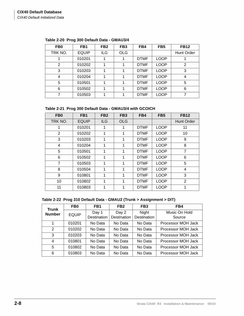
CIX40 Default DatabaseCIX40 Default Initialized Data
2-8 Strata CIX40 R3 Installation & Maintenance 05/10
Table 2-20 Prog 300 Default Data - GMAU3/4
FB0 FB1 FB2 FB3 FB4 FB5 FB12
TRK NO. EQUIP ILG OLG Hunt Order
1 010201 1 1 DTMF LOOP 1
2 010202 1 1 DTMF LOOP 2
3 010203 1 1 DTMF LOOP 3
4 010204 1 1 DTMF LOOP 4
5 010501 1 1 DTMF LOOP 5
6 010502 1 1 DTMF LOOP 6
7 010503 1 1 DTMF LOOP 7
Table 2-21 Prog 300 Default Data - GMAU3/4 with GCOICH
FB0 FB1 FB2 FB3 FB4 FB5 FB12
TRK NO. EQUIP ILG OLG Hunt Order
1 010201 1 1 DTMF LOOP 11
2 010202 1 1 DTMF LOOP 10
3 010203 1 1 DTMF LOOP 9
4 010204 1 1 DTMF LOOP 8
5 010501 1 1 DTMF LOOP 7
6 010502 1 1 DTMF LOOP 6
7 010503 1 1 DTMF LOOP 5
8 010504 1 1 DTMF LOOP 4
9 010801 1 1 DTMF LOOP 3
10 010802 1 1 DTMF LOOP 2
11 010803 1 1 DTMF LOOP 1
Table 2-22 Prog 310 Default Data - GMAU2 (Trunk > Assignment > DIT)
TrunkNumber
FB0 FB1 FB2 FB3 FB4
EQUIPDay 1
DestinationDay 2
DestinationNight
DestinationMusic On Hold
Source
1 010201 No Data No Data No Data Processor MOH Jack
2 010202 No Data No Data No Data Processor MOH Jack
3 010203 No Data No Data No Data Processor MOH Jack
4 010801 No Data No Data No Data Processor MOH Jack
5 010802 No Data No Data No Data Processor MOH Jack
6 010803 No Data No Data No Data Processor MOH Jack
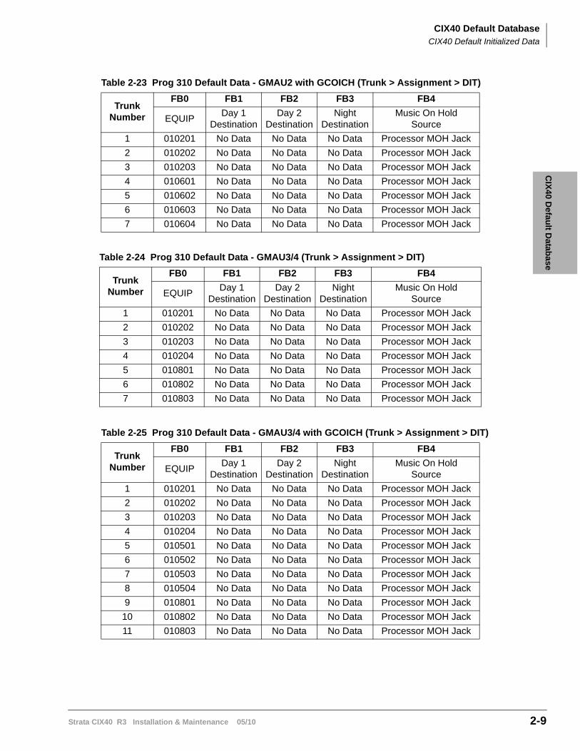
CIX
40 Defau
lt Datab
aseCIX40 Default Database
CIX40 Default Initialized Data
Strata CIX40 R3 Installation & Maintenance 05/10 2-9
Table 2-23 Prog 310 Default Data - GMAU2 with GCOICH (Trunk > Assignment > DIT)
TrunkNumber
FB0 FB1 FB2 FB3 FB4
EQUIPDay 1
DestinationDay 2
DestinationNight
DestinationMusic On Hold
Source
1 010201 No Data No Data No Data Processor MOH Jack
2 010202 No Data No Data No Data Processor MOH Jack
3 010203 No Data No Data No Data Processor MOH Jack
4 010601 No Data No Data No Data Processor MOH Jack
5 010602 No Data No Data No Data Processor MOH Jack
6 010603 No Data No Data No Data Processor MOH Jack
7 010604 No Data No Data No Data Processor MOH Jack
Table 2-24 Prog 310 Default Data - GMAU3/4 (Trunk > Assignment > DIT)
TrunkNumber
FB0 FB1 FB2 FB3 FB4
EQUIPDay 1
DestinationDay 2
DestinationNight
DestinationMusic On Hold
Source
1 010201 No Data No Data No Data Processor MOH Jack
2 010202 No Data No Data No Data Processor MOH Jack
3 010203 No Data No Data No Data Processor MOH Jack
4 010204 No Data No Data No Data Processor MOH Jack
5 010801 No Data No Data No Data Processor MOH Jack
6 010802 No Data No Data No Data Processor MOH Jack
7 010803 No Data No Data No Data Processor MOH Jack
Table 2-25 Prog 310 Default Data - GMAU3/4 with GCOICH (Trunk > Assignment > DIT)
TrunkNumber
FB0 FB1 FB2 FB3 FB4
EQUIPDay 1
DestinationDay 2
DestinationNight
DestinationMusic On Hold
Source
1 010201 No Data No Data No Data Processor MOH Jack
2 010202 No Data No Data No Data Processor MOH Jack
3 010203 No Data No Data No Data Processor MOH Jack
4 010204 No Data No Data No Data Processor MOH Jack
5 010501 No Data No Data No Data Processor MOH Jack
6 010502 No Data No Data No Data Processor MOH Jack
7 010503 No Data No Data No Data Processor MOH Jack
8 010504 No Data No Data No Data Processor MOH Jack
9 010801 No Data No Data No Data Processor MOH Jack
10 010802 No Data No Data No Data Processor MOH Jack
11 010803 No Data No Data No Data Processor MOH Jack
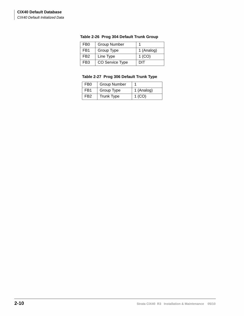
CIX40 Default DatabaseCIX40 Default Initialized Data
2-10 Strata CIX40 R3 Installation & Maintenance 05/10
Table 2-26 Prog 304 Default Trunk Group
FB0 Group Number 1
FB1 Group Type 1 (Analog)
FB2 Line Type 1 (CO)
FB3 CO Service Type DIT
Table 2-27 Prog 306 Default Trunk Type
FB0 Group Number 1
FB1 Group Type 1 (Analog)
FB2 Trunk Type 1 (CO)
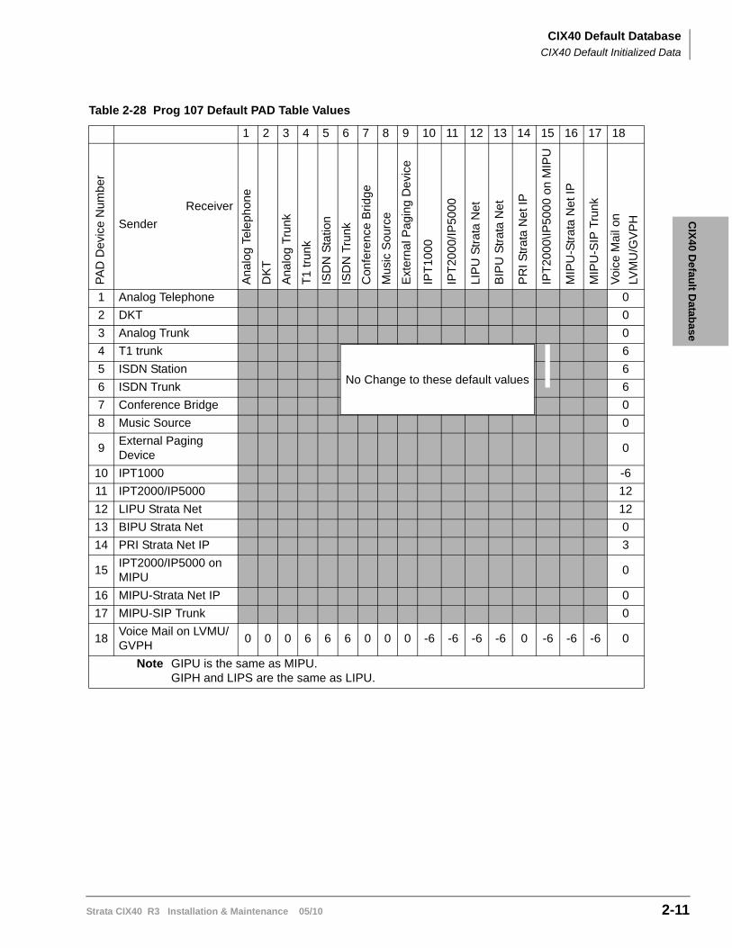
CIX
40 Defau
lt Datab
aseCIX40 Default Database
CIX40 Default Initialized Data
Strata CIX40 R3 Installation & Maintenance 05/10 2-11
Table 2-28 Prog 107 Default PAD Table Values
1 2 3 4 5 6 7 8 9 10 11 12 13 14 15 16 17 18
PA
D D
evic
e N
umbe
r
Receiver
Sender
Ana
log
Tel
eph
one
DK
T
Ana
log
Tru
nk
T1
trun
k
ISD
N S
tatio
n
ISD
N T
runk
Con
fere
nce
Brid
ge
Mus
ic S
ourc
e
Ext
ern
al P
agi
ng
De
vice
IPT
100
0
IPT
200
0/IP
500
0
LIP
U S
tra
ta N
et
BIP
U S
tra
ta N
et
PR
I Str
ata
Net
IP
IPT
200
0\IP
500
0 on
MIP
U
MIP
U-S
tra
ta N
et I
P
MIP
U-S
IP T
run
k
Vo
ice
Mai
l on
LVM
U/G
VP
H
1 Analog Telephone 0
2 DKT 0
3 Analog Trunk 0
4 T1 trunk 6
5 ISDN Station 6
6 ISDN Trunk 6
7 Conference Bridge 0
8 Music Source 0
9External Paging Device
0
10 IPT1000 -6
11 IPT2000/IP5000 12
12 LIPU Strata Net 12
13 BIPU Strata Net 0
14 PRI Strata Net IP 3
15IPT2000/IP5000 on MIPU
0
16 MIPU-Strata Net IP 0
17 MIPU-SIP Trunk 0
18Voice Mail on LVMU/GVPH
0 0 0 6 6 6 0 0 0 -6 -6 -6 -6 0 -6 -6 -6 0
Note GIPU is the same as MIPU.GIPH and LIPS are the same as LIPU.
No Change to these default values
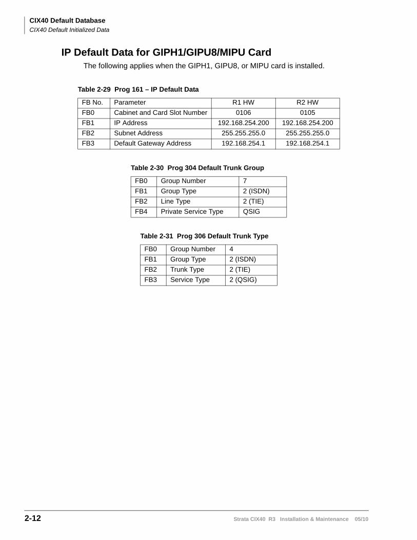
CIX40 Default DatabaseCIX40 Default Initialized Data
2-12 Strata CIX40 R3 Installation & Maintenance 05/10
IP Default Data for GIPH1/GIPU8/MIPU CardThe following applies when the GIPH1, GIPU8, or MIPU card is installed.
Table 2-29 Prog 161 – IP Default Data
FB No. Parameter R1 HW R2 HW
FB0 Cabinet and Card Slot Number 0106 0105
FB1 IP Address 192.168.254.200 192.168.254.200
FB2 Subnet Address 255.255.255.0 255.255.255.0
FB3 Default Gateway Address 192.168.254.1 192.168.254.1
Table 2-30 Prog 304 Default Trunk Group
FB0 Group Number 7
FB1 Group Type 2 (ISDN)
FB2 Line Type 2 (TIE)
FB4 Private Service Type QSIG
Table 2-31 Prog 306 Default Trunk Type
FB0 Group Number 4
FB1 Group Type 2 (ISDN)
FB2 Trunk Type 2 (TIE)
FB3 Service Type 2 (QSIG)
CIX
40 Defau
lt Datab
aseCIX40 Default Database
Call Monitor
Strata CIX40 R3 Installation & Maintenance 05/10 2-13
Call MonitorUsing the flexible Call Monitor button on your telephone, you can listen to the message a caller is recording in your voice mailbox. You can also answer the call and talk to the caller anytime during the message recording.
To enable Call Monitor on your telephone
1. While on hook, press the idle Call Monitor button. The button’s LED flashes red.
2. Enter your voice mail password (maximum of 16 digits; numbers 0~9).
3. Press #. The password displays with *. The LCD now displays “Call Monitor Enabled” briefly and then displays the original information. The Call Monitor LED turns solid red indicating that the feature is enabled.
To disable Call Monitor on your telephone
With the Call Monitor LED solid red, press Call Monitor. The Call Monitor LED turns off.
To monitor a call using Call Monitor
A flashing red Call Monitor LED indicates that a message is being recorded in voice mail.
Using the speakerphone or handset, press Call Monitor. The Call Monitor LED lights green. You can hear the caller leaving the message, but the caller cannot hear you. The LCD displays “Monitoring Voice Mail.”
To answer the call during the message recording
To talk to the caller during the recording, press Call Monitor. The recording stops and the LED turns solid red. The LCD display indicates the extension or line to which you are connected.

This page is intentionally left blank.
Strata CIX40 R3 Installation & Maintenance 05/10 3-1
CIX
40 IP Telep
ho
ny
CIX40 IP Telephony 3
This chapter introduces IP telephones and Strata Net IP on the Strata CIX40 system. It includes information specific to the GIPU8, GIPH1 and MIPU cards. The subjects of IP Telephony, in general, and IP Telephone installation are covered, in detail, in the Strata CIX and MAS Installation and Maintenance Manual.
The GIPU8, GIPH and MIPU printed circuit boards (PCB) provide the interface for Toshiba IPT telephones, SIP telephones, the Strata MAS for SES and ACD, and StrataNet applications.
The GIPU8, GIPH and MIPU have an IP network connector and an RJ-11 connector to provide an RS-232 maintenance port.
The GIPU8, GIPH and MIPU must have a static public IP address or a static private IP Address.
The GIPU8 and GIPH1 have up to eight IP channels. The MIPU16 has 16 channels, and the MIPU24 has 24 channels. These channels can be used for IP Stations, SIP stations, ACD-Voice Announce, Voice Mail, Strata Net, or any mix.
The GIPU8, GIPH and MIPU operate on the network at 100 Mbps and can be connected to a fast switch router, LAN, WAN, etc. When connecting to remote IP telephones over the Internet, a VPN router is needed to circumvent Network Address Translation (NAT) and fire wall issues.
IP Telephone, SIP Telephone, SoftIPT and Strata Net IP channels require licensing. Refer to “CIX40 System Licenses” on page 1-3
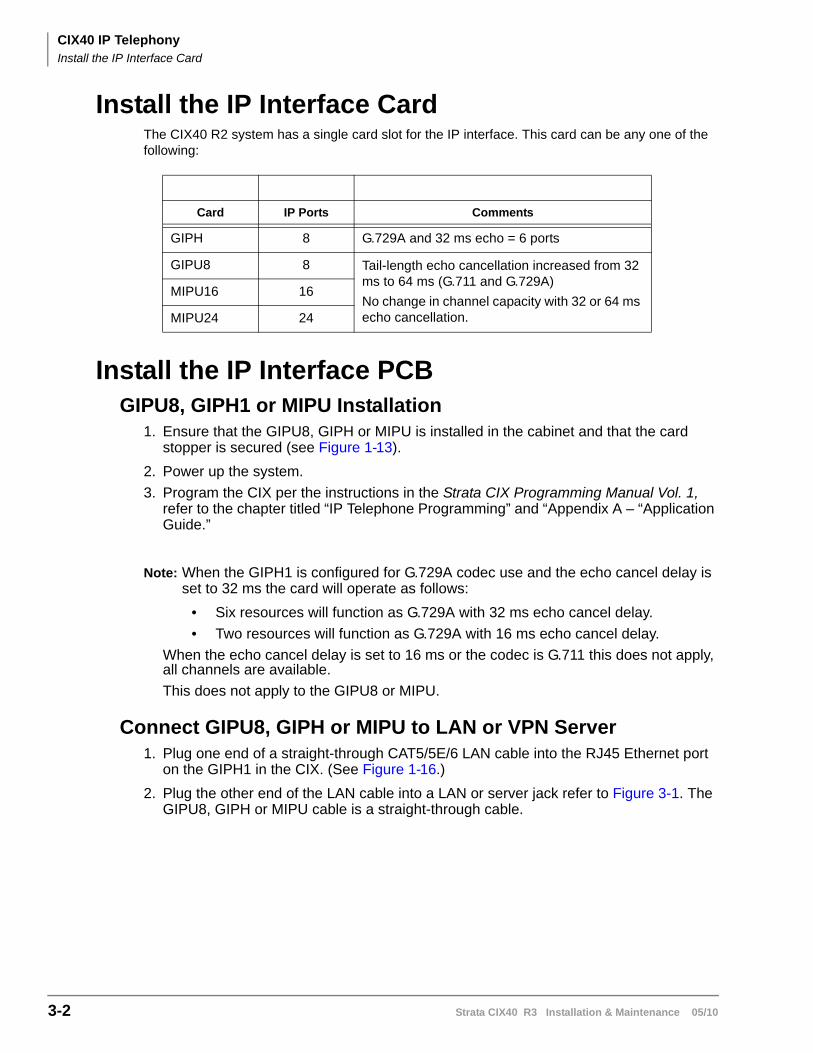
CIX40 IP TelephonyInstall the IP Interface Card
3-2 Strata CIX40 R3 Installation & Maintenance 05/10
Install the IP Interface CardThe CIX40 R2 system has a single card slot for the IP interface. This card can be any one of the following:
Install the IP Interface PCBGIPU8, GIPH1 or MIPU Installation
1. Ensure that the GIPU8, GIPH or MIPU is installed in the cabinet and that the card stopper is secured (see Figure 1-13).
2. Power up the system.
3. Program the CIX per the instructions in the Strata CIX Programming Manual Vol. 1, refer to the chapter titled “IP Telephone Programming” and “Appendix A – “Application Guide.”
Note: When the GIPH1 is configured for G.729A codec use and the echo cancel delay is set to 32 ms the card will operate as follows:
• Six resources will function as G.729A with 32 ms echo cancel delay.
• Two resources will function as G.729A with 16 ms echo cancel delay.
When the echo cancel delay is set to 16 ms or the codec is G.711 this does not apply, all channels are available.
This does not apply to the GIPU8 or MIPU.
Connect GIPU8, GIPH or MIPU to LAN or VPN Server1. Plug one end of a straight-through CAT5/5E/6 LAN cable into the RJ45 Ethernet port
on the GIPH1 in the CIX. (See Figure 1-16.)
2. Plug the other end of the LAN cable into a LAN or server jack refer to Figure 3-1. The GIPU8, GIPH or MIPU cable is a straight-through cable.
Card IP Ports Comments
GIPH 8 G.729A and 32 ms echo = 6 ports
GIPU8 8 Tail-length echo cancellation increased from 32 ms to 64 ms (G.711 and G.729A)
No change in channel capacity with 32 or 64 ms echo cancellation.
MIPU16 16
MIPU24 24
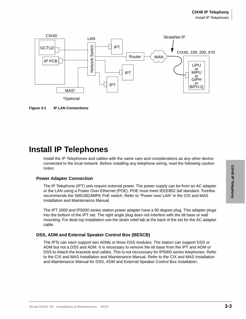
CIX40 IP TelephonyInstall IP Telephones
Strata CIX40 R3 Installation & Maintenance 05/10 3-3
CIX
40 IP Telep
ho
ny
Figure 3-1 IP LAN Connections
Install IP TelephonesInstall the IP Telephones and cables with the same care and considerations as any other device connected to the local network. Before installing any telephone wiring, read the following caution notes:
Power Adapter Connection
The IP Telephone (IPT) sets require external power. The power supply can be from an AC adapter or the LAN using a Power Over Ethernet (POE). POE must meet IEEE802.3af standard. Toshiba recommends the SMC6824MPE PoE switch. Refer to “Power over LAN” in the CIX and MAS Installation and Maintenance Manual.
The IPT 2000 and IP5000 series station power adapter have a 90 degree plug. This adapter plugs into the bottom of the IPT set. The right angle plug does not interfere with the tilt base or wall mounting. For desk top installation use the strain relief tab at the back of the set for the AC adapter cable.
DSS, ADM and External Speaker Control Box (BESCB)
The IPTs can each support two ADMs or three DSS modules. The station can support DSS or ADM but not a DSS and ADM. It is necessary to remove the tilt base from the IPT and ADM or DSS to Attach the brackets and cables. This is not neccessary for IP5000-series telephones. Refer to the CIX and MAS Installation and Maintenance Manual. Refer to the CIX and MAS Installation and Maintenance Manual for DSS, ADM and External Speaker Control Box installation.
CIX40
GCTU2
IP PCB
Net
wor
k S
witc
hMAS*
IPT
LAN
*Optional
IPT
IPT
Router WANCIX40, 100, 200, 670
StrataNet IP
LIPU
orGIPH
orBIPU-Q
MIPUor

This is the last page of the document.