stormwater technical guide for low impact development - county of santa … · stormwater technical...
TRANSCRIPT

S T O R M W A T E R T E C H N I C A L G U I D E
F O R L O W I M P A C T D E V E L O P M E N T
Compliance with
Stormwater
Post-Construction
Requirements in
Santa Barbara County
2nd Edition February 3, 2017
Project Clean Water
County of Santa Barbara
Water Resources Division

3 FEBRUARY 2017 II STORMWATER TECHNICAL GUIDE
Funding for this project has been provided in full or in part through an agreement with the State Water Resources Control Board. The contents of this document do not necessarily reflect the view and policies of the State Water Resources Control Board, nor does mention of trade names or commercial products constitute endorsement or recommendation for use.
Santa Barbara County Public Works
Water Resources Division
123 E. Anapamu St.
Santa Barbara, CA 93101
STORMWATER TECHNICAL GUIDE II I 3 FEBRUARY 2017
AGENCY CONTACTS
County of Santa Barbara Cathleen Garnand [email protected]
Includes:
• Hope Ranch
• Isla Vista
• Los Olivos
• Los Alamos
• Mission Canyon
• Mission Hills
• Montecito
• Orcutt
• Santa Ynez
• Summerland
• Toro Canyon
• Vandenburg Village
City of Buellton Rose Hess [email protected]
City of Carpinteria Erin Maker [email protected]
City of Goleta Everett King [email protected]
City of Guadalupe Jeff van den Eikhof [email protected]
City of Santa Maria Shad Springer [email protected]
City of Solvang Matt VanDerLinden, [email protected]
The cities of Santa Barbara and Lompoc are continuing their pre-existing requirements as approved by Water Board staff.
City of Santa Barbara Creeks Division Cameron Benson, [email protected]
City of Lompoc Stacy Lawson, [email protected]
CENTRAL COAST REGIONAL WATER QUALITY CONTROL BOARD
Dominic Roques [email protected]
ASSISTANCE FROM: Dan Cloak Environmental Consulting www.dancloak.com
3 FEBRUARY 2017 IV STORMWATER TECHNICAL GUIDE
P R E F A C E
In 1987, Congress amended the Clean Water Act to mandate controls on discharges from municipal separate storm sewer systems (MS4s). Acting under the Federal mandate and the California Water Code, California Water Boards issue National Pollutant Discharge Elimination System (NPDES) permits that require cities, towns, and counties to regulate activities which can result in pollutants entering their storm drains.
Municipalities implement comprehensive stormwater pollution-prevention programs. Municipal staff uses Best Management Practices (BMPs) when maintaining their own streets, storm drains, and municipal buildings. They inspect businesses and construction sites, enforce when pollutant discharges are found, educate the public, and monitor the storm drain system and receiving waters.
The comprehensive municipal programs have long included controls on new development projects. As conditions of municipal approvals and permits, development projects must control pollutant sources and reduce detain, retain, and treat specified amounts of runoff.
In July 2013, the Central Coast Water Board adopted Order R3-2013-0032, with new, more stringent Post-Construction Requirements (PCRs). Projects that receive their first discretionary approval for design elements (for example, building footprints, drainage features) after March 6, 2014—or if no discretionary approval is required, receive their first ministerial permit after that date—are subject to the PCRs, if they create or replace 2,500 square feet or more of impervious area.
The PCRs mandate that development projects use Low Impact Development (LID) to detain, retain, and treat runoff. LID incorporates and conserves on-site natural features, together with constructed hydrologic controls to more closely mimic pre-development hydrology and watershed processes.
The process of designing, checking, and building LID features and facilities into development projects can be complicated. In particular, it can be difficult to quantify the amount of runoff proposed features and facilities can detain, infiltrate, or treat and to show the LID design meets the criteria in the PCRs.
The County of Santa Barbara obtained a grant, funded by Proposition 84 and administered through the State Water Resources Control Board, to facilitate implementation of the PCRs. Grant funds enabled preparation of this Stormwater Technical Guide, a sizing calculator, templates, and other associated tools, as well as outreach and training for municipal staff and land development professionals.
Applicants for development approvals in the jurisdictions on the previous page should use this Guide when preparing Stormwater Control Plans. However, local requirements vary. Check with staff in the jurisdiction where your project is located to identify differences that may apply. A pre-application meeting is recommended for all projects subject to the PCRs.
Links
Santa Barbara County Project Clean Water http://www.sbprojectcleanwater.org/
Central Coast Regional Water Quality Control Board www.waterboards.ca.gov/centralcoast

STORMWATER TECHNICAL GUIDE V 3 FEBRUARY 2017
C O N T E N T S
Chapter 1. The Post-Construction Requirements
1-1 What Projects Must Comply
1-2 What is Low Impact Development?
Chapter 2. The Path to Stormwater Compliance
2-1 Step 1: Pre-Application Meeting
2-2 Step 2: Follow the Guide
2-2 Step 3: Stormwater Control Plan
2-2 Step 4: Draft Stormwater Facilities Operation and Maintenance Plan
2-3 Step 5: Detailed Project Design
2-3 Step 6: Construct the Project
2-3 Step 7: Transfer Maintenance Responsibility
Chapter 3. Preparing Your Stormwater Control Plan
3-1 Objectives
3-3 Step 1: Project Information
3-3 Step 2: Opportunities and Constraints
3-4 Step 3: Conceptual Site Design
3-5 Step 4: Calculations and Documentation
3-6 Step 5: Design of LID Facilities
3-6 Step 6: Source Controls
3-6 Step 7: Stormwater Facility Maintenance
3-7 Step 8: Construction Cross-Checklist
3-7 Step 9: Certification
3-8 Alternative Compliance Options
Chapter 4. Documenting Your LID Design
4-1 LID and Compliance with the PCRs
4-2 Step-by-Step
4-2 Step 1: Delineate Entire Site into Drainage Management Areas (DMAs)
3 FEBRUARY 2017 VI STORMWATER TECHNICAL GUIDE
4-3 Step 2: Categorize and Tabulate DMAs
4-3 Step 3: Select and Lay Out LID Facilities
4-4 Step 4: Size LID Facility Footprints
4-6 Step 5: Iterate Until All Facilities Meet or Exceed Minimum Area
4-7 Bioretention Facility Design Criteria
4-9 Tips for Avoiding Design Conflicts
Chapter 5. Preparing Your LID Facilities Operation and Maintenance Plan
5-1 Introduction
5-2 Step-by-Step
5-1 Step 1: Designate Responsible Individuals
5-2 Step 2: Describe the Facilities
5-2 Step 3: Document the Facilities “As Built”
5-2 Step 4: Schedule Maintenance Activities
5-3 Step 5: Compile the Plan
Tables and Checklists
1-1 Table 1-1: Requirements at a Glance
3-2 Stormwater Control Plan Checklist
3-6 Table 3-1: Format for Tabulating Potential Pollutant Sources and Source Controls
3-7 Table 3-2: Format for Stormwater Control Plan/Construction Documents Cross-Checklist
4-4 Table 4-1: Runoff Factors for Small Storms
4-10 Table 4-2: Correction Factors for Use in Calculating Equivalent Impervious Surface Area (EISA)

P R O J E C T C L E A N W A T E R
STORMWATER TECHNICAL GUIDE VII 3 FEBRUARY 2017
Figures, Design Sketches, and Design Criteria
1-2 Figure 1-1: Bioretention Facility
3-3 Figure 3-1: Illustration of Replaced Impervious Area
4-1 Figure 4-1: Derivation of Sizing Factor of 0.04 for Sizing Tier 2 Bioretention Facilities
4-3 Figure 4-2: Self-retaining Areas
4-7 Figure 4-3: Schematic of Bioretention Facility Combined with a Downstream Basin
4-11 Figure 4-4: Bioretention Facility Cross Section with Design Criteria
4-12 Figure 4-5: Bioretention Facility Plan
4-13 Figure 4-6: Porous Pavements Design Criteria
Appendices
A. Pollutant Sources and Source Control Checklist
B. Bioretention Construction Inspection Checklist
C. Technical Criteria for Non-LID Treatment Facilities
Resources
Available at www.sbprojectcleanwater.org
Stormwater Control Plan Template and Directions for Tier 1 Projects
Stormwater Control Plan Template for Tier 2 and Tier 3 Projects
Stormwater Control Measure Sizing Calculator
Example Stormwater Control Plan for a Commercial Project
Example Stormwater Control Plan for a Residential Subdivision
Example Stormwater Facilities Operation and Maintenance Plan for a Commercial Project
Example Stormwater Facilities Operation and Maintenance Plan for a Residential Subdivision
Operation and Maintenance Forms

3 FEBRUARY 2017 VIII STORMWATER TECHNICAL GUIDE
Acronyms
APN Assessor’s Parcel Number
BMP Best Management Practice
CCRs Covenants, Conditions, and Restrictions
CDP Census-Designated Place
DMA Drainage Management Area (see Chapter 4)
EISA Equivalent Impervious Surface Area, as defined in the PCRs
HOA Home Owners Association
HSG Hydrologic Soils Group (A, B, C, or D, as defined by NRCS)
LID Low Impact Development
MRSV Minimum Required Storage Volume for a Stormwater Control Measure
MS4 Municipal Separate Storm Sewer System, as defined in the Clean Water Act
NPDES National Pollutant Discharge Elimination System
NRCS Natural Resources Conservation Service (US Department of Agriculture)
O&M Operation and Maintenance
PCRs Post-Construction Requirements, adopted by the Central Coast Water Board in July 2013
SCM Stormwater Control Measure, as defined in the PCRs
SFH Single-Family Home that is not part of a larger plan of development, as defined in the PCRs
USA Urban Sustainability Area, as defined in the PCRs
C H A P T E R
STORMWATER TECHNICAL GUIDE 1-1 3 FEBRUARY 2017
T H E P O S T - C O N S T R U C T I O N R E Q U I R E M E N T S
The California Regional Water Quality Control Board for the Central Coast Region (Water Board) adopted the Post-Construction Requirements (PCRs) in July 2013. The PCRs apply in urbanized areas, including many unincorporated census-designated places (CDPs), throughout the Central Coast Region.
This Stormwater Technical Guide (Guide) details requirements for the jurisdictions listed on the inside cover. The Guide is designed to
ensure compliance with the PCRs, facilitate review of applications, and promote integrated Low Impact Development (LID) design. The Guide interprets, clarifies, and adds to the PCR requirements.
What Projects Must Comply?
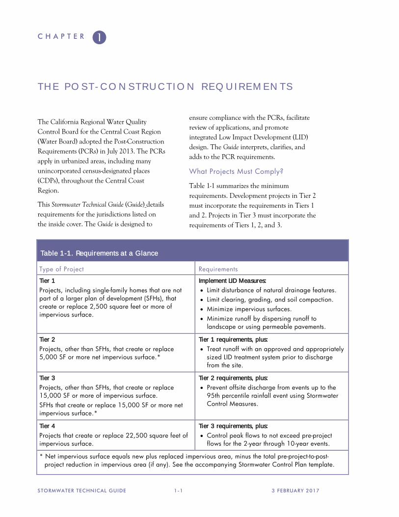
Table 1-1 summarizes the minimum requirements. Development projects in Tier 2 must incorporate the requirements in Tiers 1 and 2. Projects in Tier 3 must incorporate the requirements of Tiers 1, 2, and 3.
Table 1-1. Requirements at a Glance
Type of Project Requirements
Tier 1 Projects, including single-family homes that are not part of a larger plan of development (SFHs), that create or replace 2,500 square feet or more of impervious surface.
Implement LID Measures: • Limit disturbance of natural drainage features. • Limit clearing, grading, and soil compaction. • Minimize impervious surfaces. • Minimize runoff by dispersing runoff to
landscape or using permeable pavements.
Tier 2 Projects, other than SFHs, that create or replace 5,000 SF or more net impervious surface.*
Tier 1 requirements, plus: • Treat runoff with an approved and appropriately
sized LID treatment system prior to discharge from the site.
Tier 3 Projects, other than SFHs, that create or replace 15,000 SF or more of impervious surface. SFHs that create or replace 15,000 SF or more net impervious surface.*
Tier 2 requirements, plus: • Prevent offsite discharge from events up to the
95th percentile rainfall event using Stormwater Control Measures.
Tier 4 Projects that create or replace 22,500 square feet of impervious surface.
Tier 3 requirements, plus: • Control peak flows to not exceed pre-project
flows for the 2-year through 10-year events.
* Net impervious surface equals new plus replaced impervious area, minus the total pre-project-to-post-project reduction in impervious area (if any). See the accompanying Stormwater Control Plan template.

A B O U T T H E S T O R M W A T E R R E Q U I R E M E N T S
3 FEBRUARY 2017 1-2 STORMWATER TECHNICAL GUIDE
Projects that are located within the NPDES permit boundaries defined by the Central Coast Regional Water Quality Control Board, including cities, certain institutions, and unincorporated urban areas are subject to the PCRs. See sbprojectcleanwater.org for map of permit areas within the unincorporated portions of Santa Barbara County.
The PCRs Tier 4 requirements are consistent with Santa Barbara County flood control requirements that were previously in effect. Additional peak-flow management, based on different criteria, may be required by the local flood control agency.
All projects must also conserve natural areas, protect slopes and channels against erosion, and comply with local stream setback and tree-preservation policies as determined by local planning departments.
What is Low Impact Development?
LID design aims to mimic pre-development site hydrology as well as protect water quality. Runoff from roofs and paved areas is dispersed to landscaped areas or routed to LID facilities distributed throughout the site. These LID facilities—typically bioretention—infiltrate most runoff. During long and intense storms, underdrains convey treated stormwater to storm drains. During exceptionally large events, overflows are safely conveyed off-site. See Figure 1-1.
Some of the advantages of LID are:
• Provides effective stormwater treatment by filtration and sequestration of pollutants within soils.
• Processes pollutants through biological action in the soil, rendering some pollutants less toxic.
• Facilities can be an attractive landscape amenity.
• Quick-draining bioretention facilities do not harbor mosquitoes or other vectors.
• Maintains the natural hydrologic condition, including recharge to groundwater and contribution to stream flows.
• Requires maintenance similar to landscaped areas of similar size; no special equipment is needed.
• Above-ground, visible facilities are easy to monitor and inspect.
“Low Impact
Development is a
stormwater
management and land
development strategy
applied at the parcel
and subdivision scale
that emphasizes
conservation and the
use of on-site natural
features integrated
with engineered, small-
scale hydrologic
controls to more closely
mimic pre-development
hydrology.
— Puget Sound
Action Team, 2005
Figure 1-1. Bioretention facilities infiltrate most runoff (top) and can be an attractive landscape amenity (bottom).
C H A P T E R
STORMWATER TECHNICAL GUIDE 2-1 3 FEBRUARY 2017
T H E P A T H T O S T O R M W A T E R C O M P L I A N C E Start Early
LID features and facilities must be integrated into the planning, design, construction, operation, and maintenance of your development project.
Your LID strategy should be an integral part of the earliest decisions about how the site will be developed. Once subdivision lot lines have been sketched, or buildings and parking have been arranged on a commercial site, the LID design may already be constrained—often unnecessarily.
At this earliest stage, also consider who will be responsible for maintaining bioretention or other LID facilities in perpetuity.
The PCRs require the local municipality to maintain a database of LID facilities and ensure the facilities are operating as designed. The site layout, drainage and LID facilities are all conditions of project approval; as such, they may not be removed or rendered ineffective without the permitting agency’s approval.
In most cases, the municipality will require the property owner, by agreement, to regularly inspect the facilities, allow access for municipal inspections, and give the municipality the right to conduct remedial maintenance and recover costs if facilities are not properly maintained.
In residential subdivisions, the need to provide for maintenance of stormwater treatment facilities can affect the layout of
streets and lots, decisions whether to incorporate a homeowner’s association (HOA), liability, insurance, and capital considerations, and the value of the individual built lots. In addition, municipalities may require the builder provide an extended maintenance and warranty period for the facilities before turning them over to an HOA or other entity for maintenance in perpetuity. Again, it’s best to start early!
Here are some of the key stormwater compliance milestones as you manage your development project:
1: Pre-Application Meeting
2: Follow the Guide.
3: Stormwater Control Plan
4: Draft Stormwater Facilities
Operation and Maintenance Plan
5: Detailed Project Design
6: Construct the Project
7: Transfer Maintenance Responsibility 1: Pre-Application Meeting
Discuss stormwater requirements for your project at a pre-application meeting with planning and development staff. Their experience with similar projects and with local procedures, requirements, and community plans can provide invaluable insights. Current
“Your LID strategy
should be an integral
part of the earliest
decisions about how the
site will be developed.”
T H E P A T H T O S T O R M W A T E R C O M P L I A N C E
3 FEBRUARY 2017 2-2 STORMWATER TECHNICAL GUIDE
contacts are listed at the Project Clean Water website.
You should also discuss with staff the right timing for completing your Stormwater Control Plan. Often, site designs take a few iterative reviews (by staff and/or by a Design Review Committee) before a satisfactory site layout is achieved. It is important to consider site drainage and locations for bioretention facilities throughout this iterative process. However, it may make sense to delay compilation and formal submittal of your Stormwater Control Plan until the site layout is fairly well set.
2: Follow the Guide
Read this Guide all the way through and understand the principles and design procedures before beginning to design your project. Then, follow the steps in Chapter 3 as you lay out the site.
3: Stormwater Control Plan
Projects in Tier 1 may use the simple, abbreviated Stormwater Control Plan format and instructions in a template available on the Project Clean Water website.
For projects in Tiers 2 and 3, prepare and submit a complete Stormwater Control Plan with your application for a land use permit, or for other permits (grading or building) if planning and zoning approval is not required. The Stormwater Control Plan will demonstrate that adequate LID features and facilities can be accommodated within your site and landscape design.
Be sure the LID facilities shown on your Stormwater Control Plan Exhibit are also shown, as appropriate, on your preliminary site design, architectural design, and landscape designs.
Your Stormwater Control Plan may also be used in supporting a Negative Declaration or may be referenced in an Environmental Impact Report. In general, for most projects, implementing the techniques and criteria in this Guide will be considered to mitigate the project’s potential impacts on stormwater runoff.
If your project receives planning and zoning discretionary approval, a Condition of Approval will specify the project be constructed consistent with the Stormwater Control Plan.
As described in Chapter 3, your Stormwater Control Plan will include a Construction Checklist of items to be followed up during the final design phase of your project.
Your Stormwater Control Plan must also include a statement accepting responsibility to maintain the stormwater treatment facilities until that responsibility is transferred to the project operator or owner or another responsible party, and a commitment to execute a maintenance agreement.
4: Draft Stormwater Facilities Operation and Maintenance Plan
The LID Facilities Operation and Maintenance Plan (O&M Plan) is a living document used to plan, direct, and record maintenance of stormwater treatment facilities. It identifies the individuals responsible for maintenance, who must keep an up-to-date copy and file periodic updates with the municipality.
The O&M plan should be updated with as-built documentation of how the facilities are constructed.

P R O J E C T C L E A N W A T E R
STORMWATER TECHNICAL GUIDE 2-3 3 FEBRUARY 2017
5: Detailed Project Design
During this stage, the landscape design must integrate the functionality of LID features and facilities into the aesthetic and functional values of the project.
Typical design issues include edges and transitions to allow runoff to flow from sidewalks and paved areas into bioretention areas, dissipation of energy gained by runoff flowing down slopes, planting and irrigation of bioretention facilities, and integration of berms, fences, and walls in or near bioretention facilities.
Chapter 4 includes design suggestions and tips. As a possible starting point for preparing construction drawings, see the drawings available (in .pdf and .dwg formats) by the Central Coast Low Impact Development Initiative, www.centralcoastlidi.org.
Your submitted construction documents will include a Construction Checklist cross-referencing the Stormwater Control Plan features with the plan sheets. This checklist helps the plan checker to review the architectural, landscape, and grading and drainage plans and ensure the LID design features and facilities are integrated into the project design.
6: Construct the Project
Careful construction of LID facilities, coordinated with the building of the development, will help ensure the facilities function as intended and will also minimize future maintenance problems. Items to check during construction include:
• Avoid compaction of native soils in and around where bioretention facilities will be constructed.
• Divert any runoff flows during their construction.
• Closely follow design elevations.
• Grade parking lots, driveways, and streets to promote evenly distributed sheet flow into self-retaining landscaped areas or bioretention facilities.
• Set overflow inlets at the proper height so the surface of the bioretention facility ponds as intended.
Appendix B contains an inspection schedule and checklist for construction of bioretention facilities.
7: Transfer Maintenance Responsibility
Following construction—or perhaps following a maintenance and warranty period—formally transfer maintenance responsibility to the owner or operator of the project, who will maintain the facilities in perpetuity. In the case of a residential subdivision, this may be a homeowners association, if that arrangement has been approved by your municipality.
“Grade parking lots,
driveways and streets
to promote evenly
distributed sheet flow
into self-retaining
landscaped areas or
bioretention facilities.”


C H A P T E R
STORMWATER TECHNICAL GUIDE 3-1 3 FEBRUARY 2017
P R E P A R I N G A S T O R M W A T E R C O N T R O L P L A N
Objectives
Projects in Tier 1 may use the simple, abbreviated Stormwater Control Plan format and instructions in a template available on the Project Clean Water website.
Your Stormwater Control Plan for a Tier 2 or Tier 3 project must demonstrate your project incorporates site design characteristics, landscape features, and engineered facilities that will:
• Minimize imperviousness.
• Detain and treat, and/or retain, the specified amounts of runoff.
• Slow runoff rates.
• Reduce pollutants in post-development runoff.
You will need to show all runoff from impervious areas is either dispersed to pervious areas or is routed to a properly designed LID facility.
A complete and thorough Stormwater Control Plan will enable municipal development review staff to verify your project complies with these requirements. It is strongly recommended you retain a design professional familiar with the requirements.
Contents
Your Stormwater Control Plan will consist of a report and an exhibit. Municipal staff will use the Stormwater Control Plan Checklist (page 3-2) to evaluate the completeness of your Plan.
Step by Step
Plan and design your stormwater controls integrally with the site plan and landscaping for your project. This strategy requires you invest in early and ongoing coordination among project architects, landscape architects, geotechnical engineers, and civil engineers. However, it can pay big dividends in a cost-effective, aesthetically pleasing design—and by avoiding design conflicts later.
Your initial, conceptual design for the project should include site drainage. This should include identifying areas where runoff can be dispersed and/or the location and approximate size of stormwater treatment and flow-control facilities.
Follow these eight steps to complete your preliminary design and your Stormwater Control Plan.
Step 1: Project Information
Step 2: Opportunities and Constraints
Step 3: Conceptual Site Design
Step 4: Calculations and Documentation
Step 5: Design of LID Facilities
Step 6: Source Controls
Step 7: Stormwater Facility Maintenance
Step 8: Construction Cross-Checklist
Step 9: Certification
A template containing an example outline can be downloaded from the Project Clean Water website.
“Plan and design your
stormwater controls
integrally with the site
and landscaping for
your project.”

P R E P A R I N G A S T O R M W A T E R C O N T R O L P L A N
3 FEBRUARY 2017 3-2 STORMWATER TECHNICAL GUIDE
Stormwater Control Plan Checklist
Contents of Exhibit
Existing natural hydrologic features (depressions, watercourses, relatively undisturbed areas) and significant natural resources.
Proposed design features and surface treatments used to minimize imperviousness and reduce runoff.
Existing and proposed site drainage network and connections to drainage off-site.
Entire site divided into separate Drainage Management Areas (DMAs). Each DMA has a unique identifier and is characterized as self-retaining (zero-discharge), self-treating, or draining to a LID facility.
Proposed locations and footprints of LID facilities (also called Stormwater Control Measures, or SCMs).
Potential pollutant source areas, including loading docks, food service areas, refuse areas, outdoor processes and storage, vehicle cleaning, repair or maintenance, fuel dispensing, equipment washing, etc. listed in Appendix A.
Contents of Report
Project information including project name; application number; location; parcel numbers; applicant contact information; land use information; site area; existing, new, and replaced impervious area, and applicable PCR requirements and exceptions.
Narrative analysis or description of site features and conditions, and opportunities and constraints for stormwater control.
Narrative description of site design characteristics that protect natural resources including endangered species habitat, protected vegetation, and archaeological resources, and preserve natural drainage features, minimize imperviousness, and disperse runoff from impervious areas.
Tabulation of proposed pervious and impervious DMAs, showing self-treating areas, self-retaining areas, areas draining to self-retaining areas, and areas tributary to each LID facility.
Proposed sizes, including supporting calculations, for each LID facility.
Narrative description of each DMA and explanation of how runoff is routed from each impervious DMA to a self-retaining DMA or LID facility.
Description of site activities and potential sources of pollutants.
Table of pollutant sources identified from the list in Appendix A and for each source, the source control measure(s) used to reduce pollutants to the maximum extent practicable.
Description of signage for bioretention facilities.
General maintenance requirements for bioretention facilities and site design features.
Means by which facility maintenance will be financed and implemented in perpetuity.
Statement accepting responsibility for interim operation & maintenance of facilities.
Stormwater Construction Checklist.
Certification by a professional civil engineer, architect, or landscape architect.
P R O J E C T C L E A N W A T E R
STORMWATER TECHNICAL GUIDE 3-3 3 FEBRUARY 2017
1: Project Information
Enter the following into the Project Data Form in the Stormwater Control Plan Template:
• Project Name/Number
• Application Submittal Date
• Project Location
• Applicant Contact Information
• Project Phase
• Project Type and Description
• Project Site Area (square feet)
• Total Pre-Project Impervious Surface Area
• Total Post-Project Impervious Surface Area
• Total New Impervious Surface Area
• Total Replaced Impervious Surface Area within an Urban Sustainability Area (USA)
• Total Replaced Impervious Area not within a USA
• Watershed Management Zone
• Design Storm Frequency and Depth
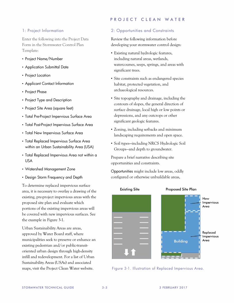
To determine replaced impervious surface area, it is necessary to overlay a drawing of the existing, pre-project impervious areas with the proposed site plan and evaluate which portions of the existing impervious areas will be covered with new impervious surfaces. See the example in Figure 3-1.
Urban Sustainability Areas are areas, approved by Water Board staff, where municipalities seek to preserve or enhance an existing pedestrian and/or public-transit-oriented urban design through high-density infill and redevelopment. For a list of Urban Sustainability Areas (USAs) and associated maps, visit the Project Clean Water website.
2: Opportunities and Constraints
Review the following information before developing your stormwater control design:
• Existing natural hydrologic features, including natural areas, wetlands, watercourses, seeps, springs, and areas with significant trees.
• Site constraints such as endangered species habitat, protected vegetation, and archaeological resources.
• Site topography and drainage, including the contours of slopes, the general direction of surface drainage, local high or low points or depressions, and any outcrops or other significant geologic features.
• Zoning, including setbacks and minimum landscaping requirements and open space.
• Soil types—including NRCS Hydrologic Soil Groups—and depth to groundwater.
Prepare a brief narrative describing site opportunities and constraints.
Opportunities might include low areas, oddly configured or otherwise unbuildable areas,
Figure 3-1. Illustration of Replaced Impervious Area.
P R E P A R I N G A S T O R M W A T E R C O N T R O L P L A N
3 FEBRUARY 2017 3-4 STORMWATER TECHNICAL GUIDE
setbacks, easements, or buffers (which can double as locations for bioretention facilities), differences in elevation (which can provide hydraulic head needed to move runoff to LID facilities), and soils favorable to infiltration.
Constraints might include impermeable soils, near-surface bedrock, high groundwater, groundwater pollution or contaminated soils, steep slopes, geotechnical instability (for example, coastal bluffs), high-intensity land use, heavy pedestrian or vehicle traffic, endangered species habitat, protected vegetation, archaeological resources, or safety concerns.
3: Conceptual Site Design
Begin by applying runoff reduction measures.
Optimize the site layout. Apply the following design principles:
• Define the development envelope and protected areas, identifying areas that are most suitable for development and areas that should be left undisturbed.
• Limit grading; preserve natural landforms and drainage patterns.
• Set back development from creeks, wetlands, and riparian habitats to the maximum degree practical and at minimum, as required by local policies.
• Preserve significant trees.
Limit paving and roofs. Where possible and consistent with zoning, design compact, taller structures, narrower and shorter streets and sidewalks, smaller parking lots (fewer stalls, smaller stalls, and more efficient lanes), and indoor or underground parking. Examine the site layout and circulation patterns and identify areas where landscaping or planter boxes can be substituted for pavement.
Use pervious pavements where possible. Inventory paved areas and identify locations where permeable pavements, such as crushed aggregate, turf block, unit pavers with permeable joints, pervious concrete, or pervious asphalt can be substituted for impervious concrete or asphalt paving. Pervious pavements are most applicable where native soils are permeable. On sites with clay soils, it may still be possible to use unit pavers or pervious pavement with a sufficiently deep and well-drained base course. Pervious pavements such as turf block can sometimes be used for overflow parking or for emergency access lanes (check with the local fire department).
Direct drainage to landscaped areas. There are two options for handling runoff from impervious areas:
• Disperse runoff to lawns or landscaping. Limit the ratio of impervious to pervious area to 2:1 maximum. Pervious areas must be relatively flat, and the surface should be graded to a slightly concave surface to create a “self-retaining” area. Sites in densely urbanized areas are often too constrained to implement this option.
• Route runoff to LID facilities (also called Stormwater Control Measures, or SCMs). LID facilities detain and infiltrate runoff. For rough site layout, consider that the surface area of a bioretention facility will be between 4% and 10% of tributary impervious area.
See Chapter 4 for design criteria for self-retaining areas and bioretention facilities.
Tips for Conceptual Drainage Design.
Most LID facilities are bioretention facilities and include underdrains. A bioretention facility requires two to four feet of head from
P R O J E C T C L E A N W A T E R
STORMWATER TECHNICAL GUIDE 3-5 3 FEBRUARY 2017
the inlet to the underdrain outlet, which can be the connected to an underground storm drain or daylighted.
On flat sites, it usually works best to intersperse self-retaining areas and bioretention facilities throughout the site. Grade parking lots, and driveways to sheet flow runoff directly into the landscaped areas. Use valley gutters or trench drains, rather than underground pipes, to convey runoff longer distances.
On sloped sites, it may work better to collect upslope runoff in conventional catch basins and pipe it to downslope bioretention facilities.
Use the head from roof downspouts by connecting leaders all the way to landscaping or bioretention facilities. Where necessary, bubble-ups can be used to disperse piped runoff.
Siting LID facilities/SCMs. Facilities should be easily accessible for inspection and maintenance.
In commercial, mixed-use, and multi-family developments, facilities can be located in parking medians, parking islands, street setbacks, side and rear setbacks, and other landscaped areas.
In residential subdivisions, the most practical strategy may be to drain the lots to the street in the conventional manner, and then drain the street to a bioretention area. It is most advantageous to create a separate parcel or parcels owned in common, which can double as a landscape amenity or a park. (This is one reason why it is important to plan stormwater treatment and flow-control before drawing subdivision lot lines.) Facilities in back or side yards should be avoided. If facilities are located on individual lots, prospective buyers
may find undesirable the necessary legal restrictions on what they can do with those facilities.
Other types of treatment facilities. Bioretention facilities can typically be fit into parking medians, street setbacks, foundation plantings, and other landscaping features without significantly affecting the uses or layout of the site.
Further, bioretention facilities are relatively easy to maintain, provide aesthetic appeal, attenuate peak flows, and are quite effective at removing pollutants, including pollutants associated with very fine particulates in rain and atmospheric dust.
Alternative designs should provide equal or greater protection against shock loadings and spills, and equal or greater accessibility and ease of inspection and maintenance.
In some cases, it is very difficult to accommodate bioretention facilities on smaller, densely developed sites. Tree-box-type biofilters or in-vault media filters may be used to meet Tier 2 (treatment) requirements in the following circumstances:
• Projects that create or replace an acre or less of impervious area and are located in a locally designated pedestrian-oriented district, and have at least 85% of the entire project site covered by permanent structures
• Historic sites, structures, or landscapes that cannot alter their original configuration without compromising their historic integrity.
The proposed tree-box-type biofilters or in-vault media filters must meet the criteria in Appendix C.
“Setbacks, easements,
and buffers can double
as locations for
bioretention facilities.”

P R E P A R I N G A S T O R M W A T E R C O N T R O L P L A N
3 FEBRUARY 2017 3-6 STORMWATER TECHNICAL GUIDE
4. Calculations and Documentation
Your Stormwater Control Plan must include an Exhibit showing the entire site divided into Drainage Management Areas (DMAs) and the locations and approximate sizes of LID facilities. Each should be clearly labeled so the Exhibit can be cross-referenced to the text and tables in the report.
The report will include a brief description of each DMA, including self-treating and self-retaining areas, and of each LID facility—along with tabulated calculations.
Chapter 4 includes a detailed procedure for documenting your site design and showing your LID facilities meet the minimum sizing requirements. The Central Coast Stormwater Control Measure Sizing Calculator, available on the Project Clean Water website, facilitates calculations. The calculator MS Excel file should be submitted with your Stormwater Control Plan.
5. Design of LID Facilities
Design criteria in Chapter 4 will assist you to plan for construction of LID facilities as part of your project. The criteria that apply to your planned facilities should be summarized in your Stormwater Control Plan. Anticipated exceptions to the design criteria should be noted.
6. Source Controls
Your Stormwater Control Plan must identify and describe any potential pollutant sources
that will be created or expanded as part of the development project.
Review the Pollutant Sources/Source Control Checklist (Appendix A). Begin by identifying which of the listed potential sources are associated with your project.
Then, create a table in the format shown in Table 3-1. Enter each identified source in the left-hand column. Then add the corresponding permanent, structural source controls from the Pollutant Sources/Source Control Checklist into the center column of your table.
In a narrative, explain any special features, materials, or methods of construction that will be used to implement these permanent, structural source controls.
To complete your table, refer once again to the Pollutant Sources/Source Control Checklist (Appendix A, Column 4). List the operational source controls corresponding to the sources you’ve identified into the right-hand column of your table. These controls should be implemented as long as the identified activities (sources) continue at the site. These controls may be required as a condition of a land use permit or other discretionary approval for specific uses of the site.
7. Stormwater Facility Maintenance
For Tier 2 and 3 Projects, your Stormwater Control Plan will describe maintenance needs of your LID facilities and source control
Table 3-1. Format for Source Control Table
Potential Source of Runoff Pollutants
Permanent/Structural Source Control BMPs
Operational/Pollution Prevention BMPs

P R O J E C T C L E A N W A T E R
STORMWATER TECHNICAL GUIDE 3-7 3 FEBRUARY 2017
measures. The maintenance plan will identify the location of the facilities to be inspected, the frequency of periodic inspections, and maintenance responsibilities. Maintenance records must be retained by the owner.
For residential subdivisions, consult with municipal staff, then detail the planned arrangements in your Stormwater Control Plan. Include, as available and applicable, information about joint ownership of parcels where bioretention facilities are to be located, about incorporating a homeowners association, about provisions to be incorporated in Codes, Covenants, and Restrictions, and other relevant information.
Include in your Stormwater Control Plan the following statement:
“The applicant accepts responsibility for the operation and maintenance of stormwater treatment and flow-control facilities for the life of the project. Any future change or alteration, or the failure to maintain any feature described herein can result in penalties including but not limited to fines, property liens, and other actions for enforcement of a civil judgment.”
A complete and detailed list of maintenance and inspection requirements, including inspection frequencies, will be required in your Stormwater Facilities Operation and Maintenance Plan (O&M Plan). Your O&M plan must also include detailed
documentation of how your facilities are constructed. The O&M plan will be linked to a legally binding agreement executed between the owner and the municipality. That agreement identifies the legally responsible person charged with implementing the O&M Plan over the life of the project. This agreement is a covenant running with the land, so that transfer to a new owner will transfer the responsibility for O&M.
For this stage, include in your Stormwater Control Plan a summary of the general maintenance requirements for your bioretention facilities. You will find a discussion of maintenance requirements in Chapter 5.
8. Construction Cross-Checklist
Include in your Stormwater Control Plan a Stormwater Control Plan/Construction Documents Cross-Checklist following the format in Table 3-2.
Complete the first two columns in the checklist, listing each stormwater source control measure and LID facility identified in the plan and identifying the page number where it appears.
Later, you will cut-and-paste the same table into your construction documents. Complete the rightmost column, listing the sheet number(s) where the same measure is shown on the construction plans.
Table 3-2. Format for Stormwater Control Plan/Construction Documents Cross-Checklist
Page Number in Stormwater Control Plan
Source Control or LID Facility
Plan Sheet #
P R E P A R I N G A S T O R M W A T E R C O N T R O L P L A N
3 FEBRUARY 2017 3-8 STORMWATER TECHNICAL GUIDE
9. Certification
Include the following statement by a licensed civil engineer, architect, or landscape architect:
“The preliminary design of stormwater treatment facilities and other stormwater pollution control measures in this plan are in accordance with the current edition of the Santa Barbara County Project Clean Water’s Stormwater Technical Guide.”
Alternative Compliance Options
The PCRs allow two options for alternative compliance with on-site retention requirements (Tier 3). Both require a demonstration that on-site compliance, as described above, is technically infeasible. Tier 2 (treatment) requirements must still be met on-site.
To propose alternative compliance, first prepare a complete Stormwater Control Plan as described in this chapter. Prepare your LID design as described in Chapter 4. The Stormwater Control Plan should show a complete and thorough implementation of opportunities for implementing LID, including delineation of DMAs and sizing of LID facilities. Show clearly in the plan the extent to which LID can and will be implemented on-site and explain why further implementation of LID is infeasible.
Potential causes of infeasibility include:
• High seasonal groundwater limits infiltration and/or prevents construction of subgrade stormwater control measures
• Near-surface bedrock or other impermeable conditions limit infiltration
• Soil types significantly limit infiltration
• Pollutant mobilization in soil or groundwater is a documented concern
• Space constraints imposed by infill projects, some redevelopment, and high density development, etc.
• Geotechnical hazards
• Proximity to drinking water wells (within 100’)
• Incompatibility with connections to the municipal storm drain system (for example, a project drains to an existing stormwater collection system, the elevation of which precludes connections to a properly functioning treatment or flow control facility).
Ten Percent Adjustment. Compliance with the criterion to prevent offsite discharge from events up to the 95th percentile rainfall event can be waived if stormwater control measures occupy an area equivalent to no less than 10% of the project’s “Equivalent Impervious Surface Area.”
Tabulate “Equivalent Impervious Surface Area” and the area of stormwater control measures and show totals for each; then divide the area of stormwater control measures by the Equivalent Impervious Surface Area to show the 10% criterion is met or exceeded.
Formats and instructions for this tabulation are in Chapter 4.
Off-site compliance. Nearly all development projects should be able to achieve on-site compliance using the instructions and criteria in the Guide.
If you believe on-site compliance is infeasible for your site, and you wish to propose an off-site mitigation project, begin by contacting municipal staff for further guidance.
C H A P T E R
STORMWATER TECHNICAL GUIDE 4-1 3 FEBRUARY 2017
D O C U M E N T I N G Y O U R L I D D E S I G N
LID and Compliance with the PCRs
Projects in Tier 1 may use the simple, abbreviated Stormwater Control Plan format and instructions in a template available on the Project Clean Water website.
For projects in Tier 2 and Tier 3, the following design and documentation procedure facilitates rapid and thorough evaluation of a LID design for compliance with the Post-Construction Requirements.
The procedure involves dividing the entire site into Drainage Management Areas (DMAs) and tracking the drainage from each
DMA. The procedure accounts for pervious areas and dispersal of runoff from impervious area to landscape. The procedure is iterated until LID facilities are adequately sized to treat runoff (for projects in Tier 2) or infiltrate runoff (Tier 3).
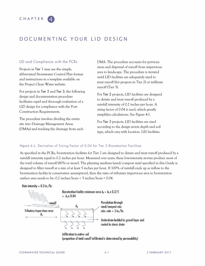
For Tier 2 projects, LID facilities are designed to detain and treat runoff produced by a rainfall intensity of 0.2 inches per hour. A sizing factor of 0.04 is used, which greatly simplifies calculations. See Figure 4-1.
For Tier 3 projects, LID facilities are sized according to the design storm depth and soil type, which vary with location. LID facilities
Figure 4-1. Derivation of Sizing Factor of 0.04 for Tier 2 Bioretention Facilities
As specified in the PCRs, bioretention facilities for Tier 2 are designed to detain and treat runoff produced by a rainfall intensity equal to 0.2 inches per hour. Measured over years, these low-intensity storms produce most of the total volume of runoff (80% or more). The planting medium (sand/compost mix) specified in this Guide is designed to filter runoff at a rate of at least 5 inches per hour. If 100% of rainfall ends up as inflow to the bioretention facility (a conservative assumption), then the ratio of tributary impervious area to bioretention surface area needs to be: 0.2 inches/hour ÷ 5 inches/hour = 0.04.

D O C U M E N T I N G Y O U R L I D D E S I G N
STORMWATER TECHNICAL GUIDE 4-2 3 FEBRUARY 2017
may be sized with a volume equal to the runoff volume produced by the design storm (simple method) or by iterative calculations routing the design storm hydrograph through the facility. These calculations account for infiltration that occurs simultaneously with inflow (routing method). The routing method results in a smaller facility; the volume and footprint vary with the characteristics of the underlying soils as well as the design storm depth.
An MS-Excel-based calculator accompanying this Guide facilitates tracking of DMAs and sizing calculations for Tier 2 and Tier 3 projects. It should be used to prepare your design and your Stormwater Control Plan submittal.
Step-by-Step
The procedure requires the following steps:
1. Delineate entire site into DMAs.
2. Categorize and tabulate DMAs. Reduce runoff by minimizing the amount of impervious area draining to bioretention facilities.
3. Select and lay out LID facilities.
4. Use the Central Coast SCM Sizing Calculator to evaluate LID facility footprints.
5. Compare the required footprint to the area available. Iterate until all bioretention facilities meet or exceed the minimum required area.
1: Delineate entire site into DMAs
Drainage Management Areas (DMAs) are portions of a project site that drain to a common point. Delineate the entire site into DMAs. Each DMA must contain only one type
of surface (e.g., landscaped, impervious, or pervious pavement).
In your Stormwater Control Plan Exhibit, lines delineating DMAs will generally follow roof ridges and grade breaks. It is advantageous to first prepare a base map using the project grading plan and roof plan, and then delineate the DMAs. This helps ensure your Stormwater Control Plan is consistent with the site plan, landscaping plan, and architectural plans.
There are four types of DMAs:
• Self-treating areas
• Self-retaining areas
• Areas draining to self-retaining areas
• Areas draining to a LID facility
Self treating areas are undisturbed areas, or areas planted with native, drought-tolerant, or LID-appropriate vegetation, that do not receive runoff from other areas. Self-treating areas do not drain to bioretention facilities, but rather drain directly off site or to the storm drain system. Examples include upslope undeveloped areas which are ditched and drained around a development and grassed slopes which drain directly to a street or storm drain. In general, self-treating areas include no impervious areas, unless the impervious area is very small (5% or less) relative to the receiving pervious area, and slopes are gentle enough to ensure runoff will be absorbed into the vegetation and soil.
Self-retaining areas are low-lying areas that retain the design storm and can also retain runoff from adjoining areas. Self-retaining areas are used where, because of site layout or topography, it is not possible to meet the conditions for self-treating areas. Self-retaining areas may have natural vegetation, or be
As a runoff reduction
measure, runoff from
impervious areas, such
as roofs, can be
managed by routing it
to self-retaining
pervious areas. The
maximum ratio is 2
parts impervious area
for every 1 part
pervious area.

P R O J E C T C L E A N W A T E R
STORMWATER TECHNICAL GUIDE 4-3 3 FEBRUARY 2017
landscaped, or may be green roofs or pervious pavement, if the pervious pavement is designed to the criteria on page 4-13. If their capacity is exceeded, self-retaining areas overflow to another DMA onsite.
To create self-retaining turf and landscape areas in flat areas or on terraced slopes, berm the area or depress the grade into a concave cross-section. Inlets of area drains, if any, should be set 3 inches or more above the low point to allow ponding.
Areas draining to self-retaining areas. Runoff from impervious areas, such as roofs, driveways, parking, and sidewalks, can be managed by routing it to self-retaining areas. The maximum ratio is 2 parts impervious area
for every 1 part pervious area. The runoff from the impervious area must be directed to and dispersed within the pervious area, and the pervious area must hold a volume equal to both areas times a 1-inch depth. For example, if the maximum ratio of two parts impervious area to one part pervious area is used, then the self-retaining pervious area must be graded concave or bermed so that
1 This
three inches of water over its surface are retained and infiltrated.1 Prolonged ponding is a potential problem at higher impervious/pervious ratios. In your design, ensure that the pervious area soils infiltrate well enough to handle the additional run-on.
Areas draining to a LID facility. The square footage of these areas is used to calculate the required footprint and volume of the LID facility. More than one drainage area (DMA) can drain to the same LID facility. However, any one DMA can only drain to one LID facility.
Where possible, design site drainage so only impervious roofs and pavement (not landscaped areas) drain to LID facilities. This yields a simpler, more efficient design and also helps protect LID facilities from becoming clogged by sediment.
2. Categorize and Tabulate DMAs
For each DMA, determine whether it will be self-treating, self-retaining, drains to a self-retaining area, or drains to a LID facility. For each DMA, tabulate the square footage and the post-project surface. Surface types and associated runoff factors are in Table 4-1.
3. Select and Lay Out LID Facilities
From your conceptual drainage design (see Chapter 3) identify the locations and footprint of LID facilities.
Design criteria for LID facilities are at the end of this chapter. Once you have laid out the LID facilities, calculate the square footage you have set aside for each LID facility.
Figure 4-2. Ratio of impervious area draining to a self-retaining area shall be no more than 2:1.
1 This scenario was simulated for a 2.4-inch storm depth (95th percentile storm for Santa Barbara) and a soil infiltration rate of 0.25 in./hr. The depth was found to be sufficient to retain and infiltrate all runoff.

D O C U M E N T I N G Y O U R L I D D E S I G N
STORMWATER TECHNICAL GUIDE 4-4 3 FEBRUARY 2017
Then, recalculate the square footage of your DMAs to omit the square footage now dedicated to LID facilities.
4. Size LID Facility Footprints
For Tier 2 projects, the minimum area for a bioretention facility can be found by summing up the contributions of each tributary DMA:
∑ (square footage × runoff factor)
and multiplying by result by the sizing factor of 0.04. This sizing factor is used by the Central Coast Region SCM Sizing Calculator that accompanies this Guide.
For Tier 3 projects, you may use either of two methods: the simple method or the routing method. The routing method is facilitated by the Central Coast Region SCM Sizing Calculator.
To use either method, first find the applicable storm depth based on location. Use the maps and instructions on the Central Coast Water Board website (search for “Central Coast percentile rainfall depth maps”). The 95th percentile storm applies throughout the areas of Santa Barbara County to which the PCRs apply. Storm depths vary from 1.4 to 2.4 inches.
Next, determine any adjustments allowed for previously existing development, as follows:
• From your project data form, identify replaced impervious square footage within
an Urban Sustainability Area (USA) and not within a USA.
• Replaced impervious square footage within a USA may be omitted from your LID facility sizing calculations (that is, multiply by zero).
• Replaced impervious square footage not within a USA may be multiplied by 0.5 before entering it into your LID facility sizing calculations.
Note that square footage omitted or halved may be applied, at your discretion, to any DMA, thereby reducing the required size of the LID facility to which that DMA is tributary.
To size facilities using the simple method: Determine the required minimum volume V (in cubic feet) for each facility by multiplying as follows:
V = Σ [DMA SF × runoff factor] × storm depth
For bioretention facilities, divide the calculated minimum storage volume by 0.4 (porosity) to determine the volume of gravel required.
To size facilities using the routing method: First, enter the following information into the calculator accompanying this Guide:
• Name and location of project
• Applicability (Tier 2, 3, or 4)
Table 4-1. Runoff Factors for Small Storms (for LID design)
Roofs and paving 1.0
Landscaped areas 0.1
Bricks or solid pavers on sand base 0.5
Pervious concrete or asphalt 0.0
Turfblock or gravel—total section min. 6" 0.0

P R O J E C T C L E A N W A T E R
STORMWATER TECHNICAL GUIDE 4-5 3 FEBRUARY 2017
• Design rainfall depth (95th percentile storm)
• Total new impervious area
• Total replaced impervious area in a USA
• Total replaced impervious area not in a USA
• Total pervious or landscaped area
Then for each, DMA, enter the following:
• Name of DMA and type (self-treating, self-retaining, drains to self-retaining, or drains to Stormwater Control Measure)
• DMA area in square feet
• Type of surface (roof, landscape, etc.)
• New or replaced and whether in a USA
• For DMAs that are not self-treating or self-retaining, the connection to a self-retaining area or Stormwater Control Measure
For each LID Facility/SCM, enter:
• Name of SCM and type (bioretention or direct infiltration; see discussion below)
• Hydrologic Soil Group or design infiltration rate for subsurface soils (see discussion below)
• Surface reservoir volume (may be entered as an average depth if reservoir area is the same as facility infiltration area)
• Facility infiltration area (area in contact with subsurface soils)
The calculator performs the following based on the Santa Barbara Unit Hydrograph method:
• Distributes the design storm depth over time increments (Type 1 unit hydrograph)
• Calculates facility inflow rate and volume for each time increment
• Calculates facility infiltration rate and, for each time increment, the corresponding infiltration volume
• Calculates incremental increase or decrease in storage and cumulative storage for each time increment
• Tracks and outputs time for facility to drain fully
The calculator outputs the maximum cumulative storage volume required to retain the design storm. As required by the PCRs, the calculator multiplies this volume by 1.2 when the drawdown time exceeds 48 hours (the likely condition when facilities are located in lower-permeability soils).
This is the Minimum Required Storage Volume to be used for your design.
Infiltration rate for routing method: You may use the default option or, alternatively, submit data from on-site testing.
The default option is to use the Hydrologic Soil Group (HSG) that best characterizes site soils. To support your selection of an HSG, attach to your Stormwater Control Plan on-site boring logs or other information such as a geotechnical report for the site. In the calculator, HSG A/B soils (soils with no significant clay component) are assigned an infiltration rate of 0.75 in/hr. and HSG C/D soils are assigned an infiltration rate of 0.25 in/hr. Should you wish to submit data from on-site testing, consult in advance with municipal staff regarding acceptable test methods.2
2 The publication “Native Soil Assessment for Small Infiltration-Based Stormwater Control Measures,” prepared for the Central Coast Low Impact Development Initiative and available at the Central Coast Water Board website, outlines some test methods

D O C U M E N T I N G Y O U R L I D D E S I G N
STORMWATER TECHNICAL GUIDE 4-6 3 FEBRUARY 2017
Because of limitations in the precision of infiltration rate testing at low rates, this option may be used only to support an infiltration of 0.5 in/hr. or greater; otherwise the default 0.25 in/hr. will apply.
For direct infiltration SCMs—such as dry wells, infiltration trenches, or infiltration basins—the calculator divides the infiltration rate by a safety factor of 2 to account for potential reductions in infiltration rates over time. (This factor may be waived by local staff if an adequately designed and maintained treatment system is installed upstream of the infiltration facility.)
For bioretention SCMs, the Minimum Required Storage Volume is the volume of the voids in the gravel layer. It is assumed the porosity Φ of the gravel layer is equal to 0.4. The underdrain is placed at the top of this layer.
Flow-control orifice on underdrain: Ordinarily, the volume of the surface reservoir and the volume of pore spaces in the planting soil are not credited toward the Minimum Required Storage Volume.
However, if a flow restrictor is placed on the underdrain outlet, once the gravel layer fills, additional inflows can be made to back up into the soil layer and the reservoir rather than immediately exiting the underdrain. By increasing the volume detained by the facility and prolonging the detention time, additional volumes are infiltrated during the largest 5% of storms. Consequently, the volume of storage beneath the underdrain can be reduced by about 20%.
When using this option, consider the potential effect of prolonged inundation on the vegetation in the bioretention facility, and select the plant palette accordingly. Also
consider the need to access the orifice for maintenance. See the schematic and criteria in Figure 4-4 on page 4-11.
To use this option, select “yes” to the option provided in the calculator. The calculator provides the diameter of the orifice. See the bioretention facility design criteria in this chapter for details on the orifice design.
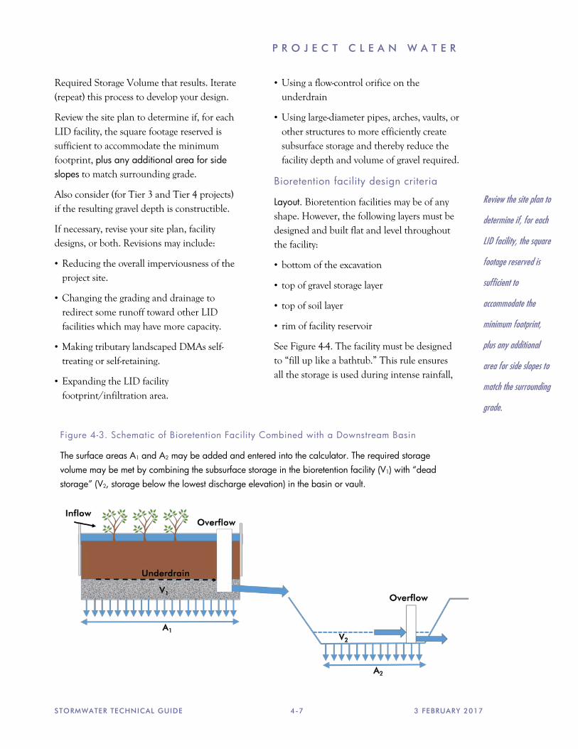
Combining with an onsite downstream basin or vault. If a bioretention facility discharges to an on-site downstream detention basin or vault (for example, a basin used for flood control detention), then the bottom surface area of the basin, and the “dead storage” volume of the basin, may be applied toward meeting the Minimum Required Storage Volume. See Figure 4-3.
To do so, add the surface area of the basin “dead storage” to the area of the bioretention subsurface gravel storage, and enter the result as the SCM in the calculator. After launching the SBUH model, the volume of the basin “dead storage” may be credited toward the minimum required storage volume.
5. Repeat until facility area is acceptable
If the routing method is used, then the minimum storage volume required changes as the facility infiltration area (this is usually, but not always, the same as the footprint) is adjusted. Try entering different facility infiltration areas into the calculator, finding the resulting minimum storage volume, and determining the resulting gravel layer depth.
The calculator is set up to track DMAs and the routing of drainage from DMAs to LID facilities/SCMs. The calculator facilitates exploration of options to delineate DMAs differently and associate DMAs with different LID facilities and calculates the Minimum
P R O J E C T C L E A N W A T E R
STORMWATER TECHNICAL GUIDE 4-7 3 FEBRUARY 2017
Required Storage Volume that results. Iterate (repeat) this process to develop your design.
Review the site plan to determine if, for each LID facility, the square footage reserved is sufficient to accommodate the minimum footprint, plus any additional area for side slopes to match surrounding grade.
Also consider (for Tier 3 and Tier 4 projects) if the resulting gravel depth is constructible.
If necessary, revise your site plan, facility designs, or both. Revisions may include:
• Reducing the overall imperviousness of the project site.
• Changing the grading and drainage to redirect some runoff toward other LID facilities which may have more capacity.
• Making tributary landscaped DMAs self-treating or self-retaining.
• Expanding the LID facility footprint/infiltration area.
• Using a flow-control orifice on the underdrain
• Using large-diameter pipes, arches, vaults, or other structures to more efficiently create subsurface storage and thereby reduce the facility depth and volume of gravel required.
Bioretention facility design criteria
Layout. Bioretention facilities may be of any shape. However, the following layers must be designed and built flat and level throughout the facility:
• bottom of the excavation
• top of gravel storage layer
• top of soil layer
• rim of facility reservoir
See Figure 4-4. The facility must be designed to “fill up like a bathtub.” This rule ensures all the storage is used during intense rainfall,
Figure 4-3. Schematic of Bioretention Facility Combined with a Downstream Basin
The surface areas A1 and A2 may be added and entered into the calculator. The required storage volume may be met by combining the subsurface storage in the bioretention facility (V1) with “dead storage” (V2, storage below the lowest discharge elevation) in the basin or vault.
Review the site plan to
determine if, for each
LID facility, the square
footage reserved is
sufficient to
accommodate the
minimum footprint,
plus any additional
area for side slopes to
match the surrounding
grade.
D O C U M E N T I N G Y O U R L I D D E S I G N
STORMWATER TECHNICAL GUIDE 4-8 3 FEBRUARY 2017
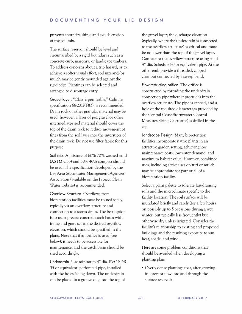
prevents short-circuiting, and avoids erosion of the soil mix.
The surface reservoir should be level and circumscribed by a rigid boundary such as a concrete curb, masonry, or landscape timbers. To address concerns about a trip hazard, or to achieve a softer visual effect, soil mix and/or mulch may be gently mounded against the rigid edge. Plantings can be selected and arranged to discourage entry.
Gravel layer. “Class 2 permeable,” Caltrans specification 68-2.02(F)(3), is recommended. Drain rock or other granular material may be used; however, a layer of pea gravel or other intermediate-sized material should cover the top of the drain rock to reduce movement of fines from the soil layer into the interstices of the drain rock. Do not use filter fabric for this purpose.
Soil mix. A mixture of 60%-70% washed sand (ASTM C33) and 30%-40% compost should be used. The specification developed by the Bay Area Stormwater Management Agencies Association (available on the Project Clean Water website) is recommended.
Overflow Structure. Overflows from bioretention facilities must be routed safely, typically via an overflow structure and connection to a storm drain. The best option is to use a precast concrete catch basin with frame and grate set to the desired overflow elevation, which should be specified in the plans. Note that if an orifice is used (see below), it needs to be accessible for maintenance, and the catch basin should be sized accordingly.
Underdrain. Use minimum 4" dia. PVC SDR 35 or equivalent, perforated pipe, installed with the holes facing down. The underdrain can be placed in a groove dug into the top of
the gravel layer; the discharge elevation (typically, where the underdrain is connected to the overflow structure) is critical and must be no lower than the top of the gravel layer. Connect to the overflow structure using solid 4" dia. Schedule 80 or equivalent pipe. At the other end, provide a threaded, capped cleanout connected by a sweep bend.
Flow-restricting orifice. The orifice is constructed by threading the underdrain connection pipe where it protrudes into the overflow structure. The pipe is capped, and a hole of the required diameter (as provided by the Central Coast Stormwater Control Measures Sizing Calculator) is drilled in the cap.
Landscape Design. Many bioretention facilities incorporate native plants in an attractive garden setting, achieving low maintenance costs, low water demand, and maximum habitat value. However, combined uses, including active uses on turf or mulch, may be appropriate for part or all of a bioretention facility.
Select a plant palette to tolerate fast-draining soils and the microclimate specific to the facility location. The soil surface will be inundated briefly and rarely (for a few hours on possibly up to 5 occasions during a wet winter, but typically less frequently) but otherwise dry unless irrigated. Consider the facility’s relationship to existing and proposed buildings and the resulting exposure to sun, heat, shade, and wind.
Here are some problem conditions that should be avoided when developing a planting plan:
• Overly dense plantings that, after growing in, prevent flow into and through the surface reservoir

P R O J E C T C L E A N W A T E R
STORMWATER TECHNICAL GUIDE 4-9 3 FEBRUARY 2017
• Aggressive roots that block inflow or percolation
• Invasive weeds
• Plants that need irrigation or fertilization
Trees and large shrubs installed in bioretention facilities are susceptible to blowing over before roots are established. They should be staked securely. Three stakes per tree are recommended at windy sites.
Aged mulch, also called compost mulch, reduces the ability of weeds to establish, keeps the soil mix moist, and replenishes soil nutrients. Compared to bark mulch, aged mulch has somewhat less tendency to float into overflow inlets during intense storms.
Irrigation. Irrigation controls should allow separate control of times and durations of irrigation for bioretention facilities vs. other landscape areas. Smart irrigation controllers are strongly encouraged. Available controllers can access weather stations, use sensors to measure soil temperature and moisture, and allow input of soil types, plant types, root depth, light conditions, slope, and usable rainfall. Bioretention facilities may need to be irrigated more than once a day, depending on the plants selected.
Drip emitters are strongly recommended over spray irrigation. Use multiple, lower-flow (0.5 to 2 gallons per hour) emitters—two to four emitters for perennials, ground covers, and bunchgrasses; four to six emitters for larger shrubs and trees. If spray heads are used, they must be positioned to avoid direct spray into outlet structures.
Signage. Each bioretention facility must include a sign meeting current Project Clean Water standards. Signs may be available from Project Clean Water; check for availability.
Signs must be visible to site users and to maintenance personnel.
Tips for avoiding design conflicts
Review your bioretention design for the following:
• Elevations all around each facility are consistent with grading, drainage, and paving plans, and with architectural plans.
• Facilities do not interfere with circulation or with pedestrian access between parking areas and building entrances.
• Facilities are represented in architectural and landscape renderings.
• Bioretention facilities are shown in landscape plans, and a suitable plant palette has been chosen.
• Cable vaults, phone vaults, electrical boxes, and other utility boxes are accommodated in designated locations outside the bioretention facilities.
• Foundations and pavement subgrades adjacent to the facilities are shored and protected against moisture intrusion, as needed.
Designing SCMs Other than Bioretention
For dry wells, infiltration trenches, infiltration basins, and other retention facilities, demonstrate that your preliminary design meets the proposed infiltration area and Minimum Required Storage Volume (as shown in the calculator file submitted with your Stormwater Control Plan). Standard designs for these facilities may be used. Links to some design guidance manuals are on the Project Clean Water website.

D O C U M E N T I N G Y O U R L I D D E S I G N
STORMWATER TECHNICAL GUIDE 4-10 3 FEBRUARY 2017
Ten Percent Adjustment
As noted in Chapter 3, following determination that it is infeasible to incorporate facilities that will detain the specified amount of runoff on-site, compliance may be achieved by dedicating a minimum 10% of the site’s “Equivalent Impervious Surface Area” (EISA) to Stormwater Control Measures (SCMs).
Calculation of EISA. Divide the site into DMAs. Delineate separate DMAs for each surface type.
Tabulate and total the square footage of DMAs with concrete or asphalt paving, conventional or metal roofs, or other wholly impervious surfaces.
Then tabulate the square footage of DMAs with the surfaces shown in Table 4-6. Multiply the square footage of each DMA by the “correction factor” shown and total the products.
Total the contributions of the pervious and partially pervious DMAs. This is the EISA for the site.
Calculation of SCM Area. Total the square footage of bioretention facilities and other facilities designed using the simple method or the calculator.
Ratio. Divide the SCM Area by the EISA to determine if the 10% criterion is met. Use of the 10% adjustment requires that the applicant first demonstrate the infeasibility of implementing bioretention facilities sized using the calculator to manage runoff from all impervious DMAs. The project must retain on-site the amount of runoff feasible.
Table 4-2. Correction Factors for Use in Calculating Equivalent Impervious Surface Area (EISA) (from the PCRs)
Pervious Surface
Correction Factor Pervious concrete 0.60
Cobbles 0.60
Pervious Asphalt 0.55
Natural Stone (without grout) 0.25
Turf Block 0.15
Brick (without grout) 0.13
Unit Pavers on Sand 0.10
Crushed Aggregate 0.10
Grass 0.10

P R O J E C T C L E A N W A T E R
STORMWATER TECHNICAL GUIDE 4-11 3 FEBRUARY 2017

D O C U M E N T I N G Y O U R L I D D E S I G N
STORMWATER TECHNICAL GUIDE 4-12 3 FEBRUARY 2017

P R O J E C T C L E A N W A T E R
STORMWATER TECHNICAL GUIDE 4-13 3 FEBRUARY 2017
Figure 4-6: Design Criteria for porous pavements to achieve runoff reduction
The following minimum design criteria must be followed where porous pavements are used as a site design measure for Tier 1 projects, or a self-retaining area for Tier 2 and 3 projects. As with other areas draining to self-retaining areas (p. 4-3), porous pavements built to these criteria may receive runoff from impervious areas up to a ratio of 2:1 impervious-to-pervious, if the soils underlying the porous pavement drain well enough to handle the additional run-on.
No erodible areas drain on to permeable pavement.
Subgrade is level and slopes are not so steep that subgrade is prone to erosion.
Subgrade compaction is minimal.
Reservoir base course is of open-graded crushed stone. Base depth (3" or more) is adequate to retain rainfall and support design loads (more depth may be required).
No subdrain is included or, if a subdrain is included, outlet elevation is a minimum of 3 inches above bottom of base course/top of subgrade.
Rigid edge is provided to retain granular pavements and unit pavers.
Solid unit pavers, if used, are set in sand or gravel with minimum 3/8 inch gaps between the pavers. Joints are filled with an open-graded aggregate free of fines.
Permeable concrete or porous asphalt, if used, are installed by industry-certified professionals according to the vendor’s recommendations.
Selection and location of pavements incorporates Americans with Disabilities Act requirements (if applicable), site aesthetics, and uses.
concrete unit pavers
sand setting bed
reservoir base course
Typical configuration for a pervious pavement. The base course is a minimum 3" depth for runoff retention. A deeper base course is typically required for pavement stability.

C H A P T E R
STORMWATER TECHNICAL GUIDE 5-1 3 FEBRUARY 2017
P R E P A R I N G Y O U R B I O R E T E N T I O N F A C I L I T I E S O P E R A T I O N & M A I N T E N A N C E P L A N
Introduction
LID facilities—and in particular, bioretention facilities—require little care beyond normal maintenance and periodic rejuvenation of the landscaping.
However, applicants must verify provisions have been made for maintenance of the LID facilities in perpetuity.
This verification is accomplished by executing and recording an agreement that “runs with the land.” The agreement provides the municipality a right of access for inspections and requires the owner to certify annually that facilities have been recently inspected and are functioning as intended. If maintenance is not adequate, the municipality may conduct any maintenance or repairs needed and bill the owner to recover costs. The agreement is binding on future owners of the entire property or any subdivided portion of the property. A model agreement is available at the Project Clean Water website.
When facilities are located in a privately owned common area, such as street or landscaped area within a residential subdivision, the joint responsibilities of the property owners must be spelled out in Covenants, Conditions, and Restrictions (CC&Rs).
Your Operation and Maintenance Plan (O&M Plan) will address the specific drainage patterns and treatment facilities on the development site and is typically referenced in the agreement or attached as an exhibit. The O&M Plan is used to plan, direct, and record maintenance of the SCMs. The O&M Plan is kept on-site, and a copy maintained at municipal offices.
Updated information, including contact information, must be provided to the municipality whenever a property is sold and whenever responsibility for maintenance is changed.
Step by Step
Follow these five steps to prepare your O&M Plan.
Step 1: Designate Responsible Individuals
Step 2: Describe the Facilities
Step 3: Document the Facilities “As Built”
Step 4: Schedule Maintenance Activities
Step 5: Compile the Plan
1. Designate Responsible Individuals.
Identify the following individuals:
• Person who will have direct responsibility for the maintenance of stormwater controls, maintain self-inspection records, and sign

O P E R A T I O N A N D M A I N T E N A N C E O F F A C I L I T I E S
3 FEBRUARY 2017 5-2 STORMWATER TECHNICAL GUIDE
any correspondence with the municipality regarding the inspections.
• Employees or contractors who will report to the designated contact and are responsible for carrying out maintenance.
• Contact for response to problems, such as clogged drains or broken irrigation mains, that would require immediate response should they occur during off-hours.
Describe the methods and schedule of initial training for staff or contractors regarding the purpose, mode of operation, and maintenance requirements for the facilities on the site.
2. Describe the Facilities to be Maintained
Incorporate the following into the O&M Plan:
• Figures from your Stormwater Control Plan delineating the Drainage Management Areas on the site and showing the locations of the bioretention facilities.
• The tabulation of the Drainage Management Areas from the calculations in your Stormwater Control Plan.
3. Document Facilities “As Built”
Include from the final construction drawings:
• Plans, elevations, and details of the bioretention facilities. If necessary, annotate the drawings with the designations used in the Stormwater Control Plan so it is clear which drawing refers to which facility.
• Construction details and specifications, including depths of sand or soil, compaction, pipe materials, and bedding.
• Location and layouts of inflow piping and piping to off-site discharge.
• Native soils encountered (e.g., sand or clay lenses beneath or near facilities).
Municipalities may require a draft Operations and Maintenance Plan be submitted when building permits are applied for — or even before.
Changes made in the field during construction should be noted in the final Plan following construction.
4. Schedule Maintenance Activities
The following activities should be scheduled at least annually. The frequency should be adjusted in response to the needs of each particular facility.
Clean up. Remove any soil or debris blocking planter inlets or overflows. Remove trash that typically collects near inlets or gets caught in vegetation.
Prune or cut back plants for health and to ensure flow into inlets and across the surface of the facility. Remove and replant as necessary. When replanting, maintain the design surface elevation and minimize the introduction of soil.
Control weeds by manual methods and soil amendment. In response to problem areas or threatening invasions, corn gluten, white vinegar, vinegar-based products such as Burnout, or non-selective natural herbicides such as Safer’s Sharpshooter may be used.
Add mulch. Aged mulch, also called compost mulch, reduces the ability of weeds to establish, keeps soil moist, and replenishes soil nutrients. Mulch may be added from time to time to maintain a mulch layer thickness of 1" to 2", but only if the underlying soil surface beneath the mulch layer is a minimum 6" below the overflow elevation,
“Municipalities will
typically require a draft
Operations and
Maintenance Plan be
submitted when
building permits are
applied for — or even
before.”
P R O J E C T C L E A N W A T E R
STORMWATER TECHNICAL GUIDE 5-3 3 FEBRUARY 2017
consistently throughout the surface area of the facility.
Check signage. Remove graffiti and replace if necessary.
Check irrigation, if any, to confirm it is adequate but not excessive.
Landscape maintenance personnel should be aware of the following:
Do not add fertilizer to bioretention facilities. Compost tea, available from various nurseries and garden supply retailers, may be applied at a recommended rate of 5 gallons mixed with 15 gallons of water per acre, up to two weeks prior to planting and once per year between March and June. Do not apply when temperatures are below 50°F or above 90°F or when rain is forecast in the next 48 hours.
Do not use synthetic pesticides on bioretention facilities. Beneficial nematodes and non-toxic controls may be used. Acceptable natural pesticides include Safer® products and Neem oil.
5. Compiling the Plan
Format plans to 8½" x 11" where possible to facilitate duplication, filing, and handling. Include the revision date in the footer of each page.
Consider scanning the graphics and incorporating with the text in electronic files that can be backed up.
The following resources at the Project Clean Water website may help you when preparing your plan:
• Sample outline and format for an O&M Plan.
• Form for designating individuals responsible for operation and maintenance.
• Sample facility inspection and maintenance log.
• Sample contents of an inspector’s report.
Updates to the O&M Plan
Updates can be made, and a copy transmitted to the municipality, at any time. In particular, contact information should be updated timely.
The O&M Plan should be reviewed annually and updated as needed.
