storm water pollution prevention plan - fresno chaffee …
TRANSCRIPT
Projects/2013/213-0217/SWPPP/11-1-2016
STORM WATER POLLUTION PREVENTION PLAN
FRESNO CHAFFEE ZOO STORM DRAIN EXTENSION AND CHILDREN’S PLAY AREA
FOR
FRESNO CHAFFEE ZOO
IN
FRESNO, CA
Prepared By:
Alan Mok Engineering 7415 N. Palm Avenue, Suite 101
Fresno, CA 93711
Projects/2013/213-0217/SWPPP/11-1-2016
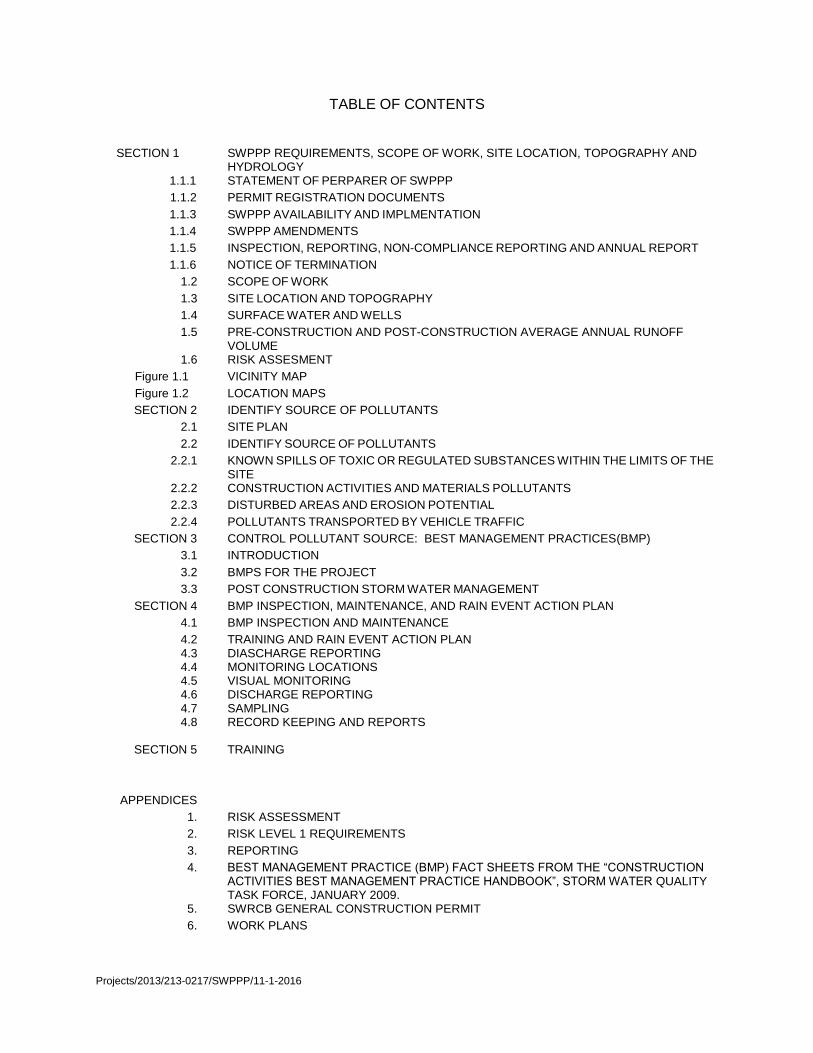
TABLE OF CONTENTS
SECTION 1 SWPPP REQUIREMENTS, SCOPE OF WORK, SITE LOCATION, TOPOGRAPHY AND
HYDROLOGY 1.1.1 STATEMENT OF PERPARER OF SWPPP
1.1.2 PERMIT REGISTRATION DOCUMENTS
1.1.3 SWPPP AVAILABILITY AND IMPLMENTATION
1.1.4 SWPPP AMENDMENTS
1.1.5 INSPECTION, REPORTING, NON-COMPLIANCE REPORTING AND ANNUAL REPORT
1.1.6 NOTICE OF TERMINATION
1.2 SCOPE OF WORK
1.3 SITE LOCATION AND TOPOGRAPHY
1.4 SURFACE WATER AND WELLS
1.5 PRE-CONSTRUCTION AND POST-CONSTRUCTION AVERAGE ANNUAL RUNOFF VOLUME
1.6 RISK ASSESMENT
Figure 1.1 VICINITY MAP
Figure 1.2 LOCATION MAPS
SECTION 2 IDENTIFY SOURCE OF POLLUTANTS
2.1 SITE PLAN
2.2 IDENTIFY SOURCE OF POLLUTANTS
2.2.1 KNOWN SPILLS OF TOXIC OR REGULATED SUBSTANCES WITHIN THE LIMITS OF THE
SITE 2.2.2 CONSTRUCTION ACTIVITIES AND MATERIALS POLLUTANTS
2.2.3 DISTURBED AREAS AND EROSION POTENTIAL
2.2.4 POLLUTANTS TRANSPORTED BY VEHICLE TRAFFIC
SECTION 3 CONTROL POLLUTANT SOURCE: BEST MANAGEMENT PRACTICES(BMP)
3.1 INTRODUCTION
3.2 BMPS FOR THE PROJECT
3.3 POST CONSTRUCTION STORM WATER MANAGEMENT
SECTION 4 BMP INSPECTION, MAINTENANCE, AND RAIN EVENT ACTION PLAN
4.1 BMP INSPECTION AND MAINTENANCE
4.2 4.3 4.4 4.5 4.6 4.7 4.8
TRAINING AND RAIN EVENT ACTION PLAN DIASCHARGE REPORTING MONITORING LOCATIONS VISUAL MONITORING DISCHARGE REPORTING SAMPLING RECORD KEEPING AND REPORTS
SECTION 5 TRAINING
APPENDICES
1. RISK ASSESSMENT
2. RISK LEVEL 1 REQUIREMENTS
3. REPORTING
4. BEST MANAGEMENT PRACTICE (BMP) FACT SHEETS FROM THE “CONSTRUCTION ACTIVITIES BEST MANAGEMENT PRACTICE HANDBOOK”, STORM WATER QUALITY TASK FORCE, JANUARY 2009.
5. SWRCB GENERAL CONSTRUCTION PERMIT
6. WORK PLANS

Projects/2013/213-0217/SWPPP/11-1-2016
SECTION 1: SWPPP REQUIREMENT, SCOPE OF WORK, SITE LOCATION, TOPOGRPAHY, AND HYDROLOGY
1.1.1STATEMENT OF PREPARER OF SWPPP AND AMENDMENTS TO SWPPP
This Storm Water Pollution Prevention Plan was prepared in accordance with the National Drainage Elimination System(NPDES) General Permit for discharges associated with constriction activities and land disturbance activities, California State Water Resource Control Board Order No. 2009-0009-DW8. This SWPPP was prepared in July 2015, under the supervision of Alan K. Mok, Project Engineer for Alan Mok Engineering.
Alan K. Mok, PE, QSD 00362 Date
“I certify under penalty of law that this document and all attachments were prepared under my direction or supervision in accordance with a system designed to assure that qualified personnel properly gather and evaluate the information submitted. Based on my inquiry of the person or persons who manage the system or those persons directly responsible for gathering the information, the information submitted is to the best of my knowledge and belief, true, accurate, and complete. I am aware that there are significant penalties for submitting false information, including the possibility of fine and imprisonment for knowing violations.”
Fresno Chaffee Zoo Fresno, CA Date
A copy of this SWPPP is on file at the job site and at the administrative office for review by regulatory personnel and local agencies. 1-1.2 Permit Regulation Documents (PRD) The owner has submitted the PRD and paid the annual fee with the SWRCB. See Attached.
Projects/2013/213-0217/SWPPP/11-1-2016
1.1.3 SWPPP Availability and Implementation A copy of this SWPPP will be on file at the job site trailer for review by regulatory personnel and local agencies. The SWPPP shall be implemented concurrently with the start of ground disruption activities as well as throughout the duration of the project. 1.1.4 SWPPP Amendments
Any increase in the total acreage covered under this SWPPP shall be amended. All amendments shall be dated and directly attached to the SWPPP as appendix. 1.1.5 Inspection, reporting, noncompliance reporting and annual report. See appendix 2 and 3 for inspection and report requirements. Violations of the Numeric Action Level and Numeric Effluent Limitation shall be reported using the SMART System. An annual report is required before 9/1 of each year, to be filed with the SWRCB. 1.1.6 Notice of Termination The notice of termination must be filed 90 days after the completion of all work. 1.2 Scope of Work This project includes the removal of vegetation and construction of play equipment, concrete improvements, utilities improvements, and turf improvements as part of the Storm Drain Extension and Children’s Play Area Improvements for Fresno Chaffee Zoo, located in Fresno, CA. The limits of the project site total approximately 0.77 acres. The major components related to construction will involve:
Removal of vegetation.
Construction of concrete improvements.
Construction of new storm drain line. 1.3 Site Location and Topography The project site is located in Fresno, CA. See Vicinity Map and Location Maps at figure 1.1 and 1.2. The site is currently a vacant lot. The existing vegetation shall be removed and the site cleared. See location map at end of the section. The existing ground is relatively flat.

Projects/2013/213-0217/SWPPP/11-1-2016
1.4 Surface Water and Wells There are is no surface water or well within the project limits. 1.5 Pre-Construction and Post Construction Average Annual Runoff Volume The normal annual rainfall at the site is approximately 11”, as determined from the Mean Annual Precipitation Map prepared by the U.S. Geological Survey, 1969. The Pre-Construction and Post Construction runoff volume is as follows:
Project Status
Runoff Coefficient
Site Area (acres)
Average Annual Rainfall (inches)
Average Annual Runoff
(acre-feet)
Pre-Construction
0.56
0.77
11”
0.40
Post-Construction
0.56
0.77
11"
0.40
1.6 Risk Assessment This project has been assessed a Risk Level of 1. See appendix 1 for the Risk Assessment on this project. See appendix 2 for the Risk Level 1 Requirements.

Projects/2013/213-0217/SWPPP/11-1-2016
Figure 1.1 and 1.2
Vicinity and Location Maps


Projects/2013/213-0217/SWPPP/11-1-2016
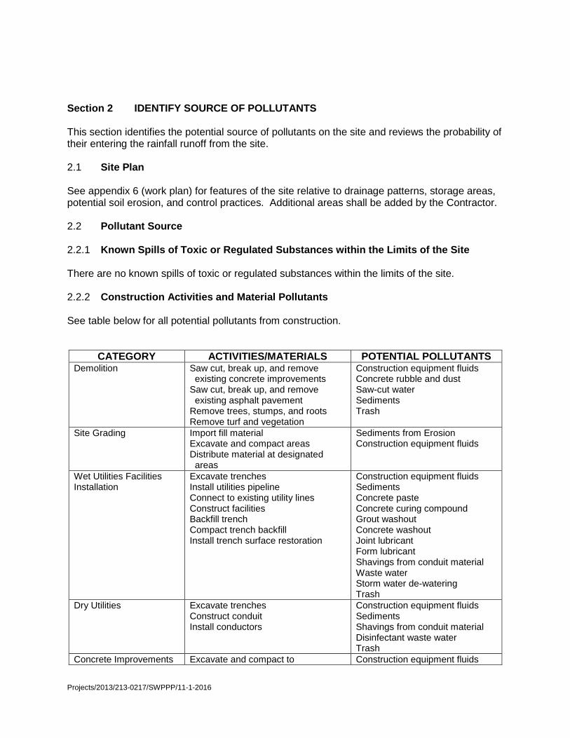
Section 2 IDENTIFY SOURCE OF POLLUTANTS This section identifies the potential source of pollutants on the site and reviews the probability of their entering the rainfall runoff from the site. 2.1 Site Plan See appendix 6 (work plan) for features of the site relative to drainage patterns, storage areas, potential soil erosion, and control practices. Additional areas shall be added by the Contractor. 2.2 Pollutant Source 2.2.1 Known Spills of Toxic or Regulated Substances within the Limits of the Site There are no known spills of toxic or regulated substances within the limits of the site. 2.2.2 Construction Activities and Material Pollutants See table below for all potential pollutants from construction.
CATEGORY ACTIVITIES/MATERIALS POTENTIAL POLLUTANTS Demolition Saw cut, break up, and remove
existing concrete improvements Saw cut, break up, and remove existing asphalt pavement Remove trees, stumps, and roots Remove turf and vegetation
Construction equipment fluids Concrete rubble and dust Saw-cut water Sediments Trash
Site Grading Import fill material Excavate and compact areas Distribute material at designated areas
Sediments from Erosion Construction equipment fluids
Wet Utilities Facilities Installation
Excavate trenches Install utilities pipeline Connect to existing utility lines Construct facilities Backfill trench Compact trench backfill Install trench surface restoration
Construction equipment fluids Sediments Concrete paste Concrete curing compound Grout washout Concrete washout Joint lubricant Form lubricant Shavings from conduit material Waste water Storm water de-watering Trash
Dry Utilities Excavate trenches Construct conduit Install conductors
Construction equipment fluids Sediments Shavings from conduit material Disinfectant waste water Trash
Concrete Improvements Excavate and compact to Construction equipment fluids
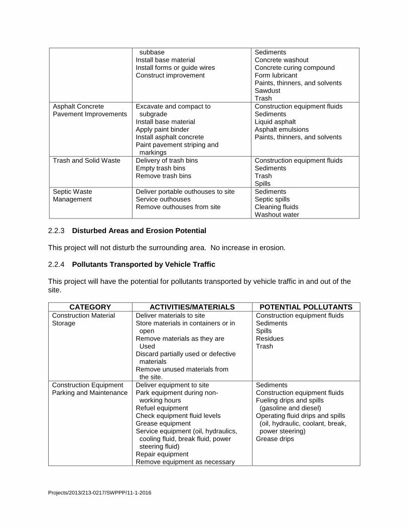
Projects/2013/213-0217/SWPPP/11-1-2016
subbase Install base material Install forms or guide wires Construct improvement
Sediments Concrete washout Concrete curing compound Form lubricant Paints, thinners, and solvents Sawdust Trash
Asphalt Concrete Pavement Improvements
Excavate and compact to subgrade Install base material Apply paint binder Install asphalt concrete Paint pavement striping and markings
Construction equipment fluids Sediments Liquid asphalt Asphalt emulsions Paints, thinners, and solvents
Trash and Solid Waste Delivery of trash bins Empty trash bins Remove trash bins
Construction equipment fluids Sediments Trash Spills
Septic Waste Management
Deliver portable outhouses to site Service outhouses Remove outhouses from site
Sediments Septic spills Cleaning fluids Washout water
2.2.3 Disturbed Areas and Erosion Potential This project will not disturb the surrounding area. No increase in erosion. 2.2.4 Pollutants Transported by Vehicle Traffic This project will have the potential for pollutants transported by vehicle traffic in and out of the site.
CATEGORY ACTIVITIES/MATERIALS POTENTIAL POLLUTANTS Construction Material Storage
Deliver materials to site Store materials in containers or in open Remove materials as they are Used Discard partially used or defective materials Remove unused materials from the site.
Construction equipment fluids Sediments Spills Residues Trash
Construction Equipment Parking and Maintenance
Deliver equipment to site Park equipment during non- working hours Refuel equipment Check equipment fluid levels Grease equipment Service equipment (oil, hydraulics, cooling fluid, break fluid, power steering fluid) Repair equipment Remove equipment as necessary
Sediments Construction equipment fluids Fueling drips and spills (gasoline and diesel) Operating fluid drips and spills (oil, hydraulic, coolant, break, power steering) Grease drips

Projects/2013/213-0217/SWPPP/11-1-2016
Section 3: CONTROL POLLUTANT SOURCE: BEST MANAGEMENT PRACTICES 3.1 Introduction The best management practices shall include two major measures. The first measure will direct the rainfall runoff away from the source to pollutants. This measure applies mainly to construction activities. The second measure is to limit contact of rainfall and runoff with sources of pollution on the site. The policies and procedures are used to direct workers and methodologies so that rainfall runoff is not polluted as a result of their actions or inactions. This measure applies to the whole project. 3.2 BMPs for the Project 3.2.1 For Sediment and Erosion
A. Install and maintain perimeter sediment controls around disturbed earth areas until disturbed soil is stabilized per SE-1, SE-5 or EC-7 (see Appendix 4).
B. Protect on-site and off-site inlets per SE-10 (see Appendix 4).
C. Dewater construction site per NS-2 (see Appendix 4) as necessary.
D. Implement no discharge of non-storm drain water to storm drainage systems.
E. Protect exposed soils on slopes that exceed 10% by directing runoff away from slopes, placing perimeter sediment control at tops of slopes per SE-1 and SE-5
(see Appendix 4) and/or with geotextile fabric or mats per EC-7 (see Appendix 4).
F. Protect all stockpiles from storm water run-off per WM-3 (see Appendix 4). 3.2.2 For Concrete paste, Concrete curing compound, Grout washout, Concrete
washout, Shavings from conduit material, Waste water, Chlorinated water, Trash, Construction equipment fluids, Sawdust, Residues, Concrete rubble and dust
A. Implement concrete washout control per WM-8 (see Appendix 4).
B. Implement concrete curing compound overspray policy per NS-12 (see Appendix 4).
C. Implement form lubricant overspray policy.
D. Discharge waste water to local sanitary sewer system
E. Discharge treated water to local sanitary sewer system.
F. Do not clean concrete tools near storm drain inlets per NS-8 (see Appendix 4).
G. Conduct dust reduction measures per WE-1 (see Appendix 4). 3.2.3 For Liquid asphalt, Asphalt emulsions, Paint thinners, Solvents, Joint lubricant,
Form lubricant, Cleaning fluid, and paint
A. Implement paving controls per NS-3 (see Appendix 4).
B. Implement bituminous sealer overspray policy
C. Store and mix paints indoors per WM-1 and WM-6 (see Appendix 4).
D. Do not paint during or immediately preceding rainfall per painting policy for this project.
E. Clean up paint and painting equipment per WM-2 (see Appendix 4).
F. Store asphalt emulsions in sealed containers until ready for use per WM-1 (see Appendix 4).
G. Do not apply asphalt emulsions during rainfall per WM-2 (see Appendix 4).

Projects/2013/213-0217/SWPPP/11-1-2016
H. Do not clean emulsion application equipment near storm drain inlets per NS-8 (see Appendix 4).
I. Excess lubricant will be wiped onto waste towels and disposed off-site.
J. Do not apply all of the above pollutants just before actual rainfall.
K. Any spill will be cleaned up per 3.2.4. 3.2.4 For Spills, Septic spills, Residues, Fuel drips and spills, Operating fluids drips and
spills, and Grease drips.
A. Only trained personnel will deliver, maintain and remove portable outhouses per WM-9 (see Appendix 4).
B. Do not place portable outhouses near storm drain inlets per WM-9 (see Appendix 4).
C. Implement spill prevention and clean-up per WM-4 (see Appendix 4).
D. Implement vehicle and equipment cleaning, fueling, and maintenance per NS-8, NS-9, and NS-10 (see Appendix 4).
E. Implement material delivery and storage per WM-1 (see Appendix 4).
F. Park vehicles and equipment at same location during non-working hours.
G. Provide drip pans under vehicles during non-working hours and clean them regularly. Store drip pans indoors when not in use.
H. Implement solid waste control per WM-5 (see Appendix 4).
I. Implement liquid waste management per WM-10 (see Appendix 4).
J. Any spills will be isolated and contained by encirclement with straw bales, dirt levees, sand bags and/or portable booms. Storm drain inlets and other connections to the storm drain system will be protected from spill material by sand bags, straw bales, or plastic sheeting weighted with dirt.
K. Spills of greater than five gallons will be reported as required by existing laws. Records of all reportable spills will be maintained on the site and at the corporate headquarters as required by law and are available for inspection by regulatory personnel.
3.2.5 For Transport Pollutants
A. Implement stabilized construction entrance per TC-1 (see Appendix 4).
B. Public streets will be cleaned of dirt tracked from the site as often as is necessary and prior to predicted rainfall per WE-1 (see Appendix 4).
C. Implement employee training/subcontractor training per CA40 (see Appendix 4).
D. Limit on-site use of vehicles by contractor and subcontractor employees to only those necessary to complete work. Require contractor and subcontractor employees to park vehicles in designated areas per WE-1 (see Appendix 4).
3.3 Post Construction Stormwater Management Measures A Post Construction BMP is required to meet local MS4 Permit or General Construction Permit standards.
Projects/2013/213-0217/SWPPP/11-1-2016
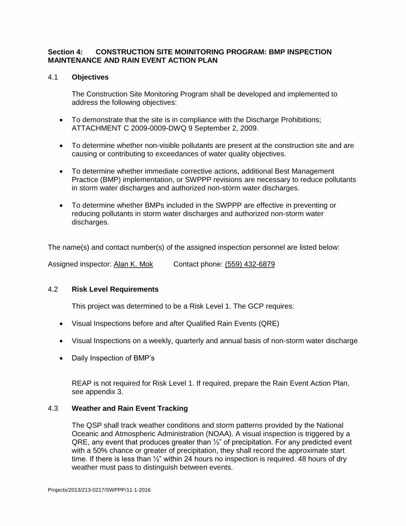
Section 4: CONSTRUCTION SITE MOINITORING PROGRAM: BMP INSPECTION MAINTENANCE AND RAIN EVENT ACTION PLAN 4.1 Objectives
The Construction Site Monitoring Program shall be developed and implemented to address the following objectives:
To demonstrate that the site is in compliance with the Discharge Prohibitions; ATTACHMENT C 2009-0009-DWQ 9 September 2, 2009.
To determine whether non-visible pollutants are present at the construction site and are causing or contributing to exceedances of water quality objectives.
To determine whether immediate corrective actions, additional Best Management Practice (BMP) implementation, or SWPPP revisions are necessary to reduce pollutants in storm water discharges and authorized non-storm water discharges.
To determine whether BMPs included in the SWPPP are effective in preventing or reducing pollutants in storm water discharges and authorized non-storm water discharges.
The name(s) and contact number(s) of the assigned inspection personnel are listed below: Assigned inspector: Alan K. Mok Contact phone: (559) 432-6879 4.2 Risk Level Requirements This project was determined to be a Risk Level 1. The GCP requires:
Visual Inspections before and after Qualified Rain Events (QRE)
Visual Inspections on a weekly, quarterly and annual basis of non-storm water discharge
Daily Inspection of BMP’s
REAP is not required for Risk Level 1. If required, prepare the Rain Event Action Plan, see appendix 3.
4.3 Weather and Rain Event Tracking
The QSP shall track weather conditions and storm patterns provided by the National Oceanic and Atmospheric Administration (NOAA). A visual inspection is triggered by a QRE, any event that produces greater than ½” of precipitation. For any predicted event with a 50% chance or greater of precipitation, they shall record the approximate start time. If there is less than ½” within 24 hours no inspection is required. 48 hours of dry weather must pass to distinguish between events.

Projects/2013/213-0217/SWPPP/11-1-2016
4.4 Monitoring Locations
The on-site trained inspector and QSP shall inspect all area within boundary of project or within perimeter protection. Access point to the site, any construction, vehicle staging area and BMP (inlet or perimeter) shall be monitored.
4.5 Visual Monitoring
The QSP or a trained on-site inspector shall visually inspect site on a weekly basis for deficiencies. Trained on-site inspector must submit a digital copy of weekly inspection reports to the QSD on regular basis, or immediately if are found. Original report will be keep on-site.
4.5.1 Routine Monitoring and Inspections
The routine weekly inspections shall include checking the site for any discharges and inspecting the installed BMPs. BMPs found to be damaged or broken shall be immediately repaired to specified requirements. Any contaminates found, by leaks or other sources, shall be cleaned accordingly and immediately. The roadways impacted by the construction and the entrance to the site shall be swept weekly or whenever sediment has been observed. The contractor will be in charge of these inspections after being trained and will submit electronic copies of the reports to the QSD while keeping the originals on-site.
4.5.2 QRE Triggered Inspections
Visual observations of the site and BMPs triggered by a QRE are required before, after and every 24-hr during a qualifying event. The QSP shall track weather condition and storm patterns Prior to the QRE, the QSP shall visually inspect the site. The QSP shall inspect all installed BMPs for damage and construction areas for leaks, spills or other sources of contaminates. If the QRE last longer than 24 hours, the QSP shall make a site visit during the storm, during working hours and in safe conditions, to inspect site for any breaches or discharges. Within 48 hours of end of QRE, the QSP must visually inspect the site to determine if any discharges occurred, BMP’s need repair or any additional BMPs need to be installed. QSP will
4.6 Discharge Reporting
If a discharge occurs or if the project receives a written notice or order from any regulatory agency, the contractor will immediately notify the Resident Engineer, and will
Projects/2013/213-0217/SWPPP/11-1-2016
file a written report to the Resident Engineer within 2 days of the discharge event, notice, or order. Corrective measures will be implemented immediately following the discharge, notice or order. All discharges will be documented on a Discharge Reporting Log.
Discharges requiring reporting include:
o Storm water from a DSA discharged to a waterway without treatment by a temporary construction BMP;
o Non-storm water, except conditionally exempted discharges, discharged to a waterway or a storm drain system, without treatment by an approved control measure (BMP);
o Storm water discharged to a waterway or a storm drain system where the control measures (BMPs) have been overwhelmed or not properly maintained or installed;
o Discharge of hazardous substances above the reportable quantities in 40 CFR 110.3, 117.3 or 302.4;
o Storm water runoff containing hazardous substances from spills discharged to a waterway or storm drain system;
o Where water quality sample results from a CWA Section 303(d) stream listed for sediment, siltation or turbidity indicate elevated levels of sediment or turbidity in downstream samples;
o Where water quality sample results indicate elevated levels of non-visible pollutants;
o Discharges that may endanger health or the environment; and
o Other discharge reporting as directed by the Resident Engineer.
The report to the Resident Engineer will contain the following items: o The date, time, location, nature of operation, and type of unauthorized discharge,
including the cause or nature of the notice or order;
o The control measures (BMPs) deployed before the discharge event, or prior to receiving notice or order;
o The date of deployment and type of control measures (BMPs) deployed after the discharge event, or after receiving the notice or order, including additional measures installed or planned to reduce or prevent re-occurrence; and
o An implementation and maintenance schedule for any affected BMPs.
4.7 Sampling
Samples shall be collected at the designated sampling locations shown on the Site Maps and listed in the preceding sections. Samples shall be collected, maintained and shipped in accordance with the SWAMP 2008 Quality Assurance Program Plan (QAPrP).
Projects/2013/213-0217/SWPPP/11-1-2016
Grab samples shall be collected and preserved in accordance with the methods identified in preceding sections. To maintain sample integrity and prevent cross-contamination, sample collection personnel shall follow the protocols below.
Collect samples (for laboratory analysis) only in analytical laboratory-provided sample
containers;
Wear clean, powder-free nitrile gloves when collecting samples;
Change gloves whenever something not known to be clean has been touched;
Change gloves between sites;
Decontaminate all equipment (e.g. bucket, tubing) prior to sample collection using a
trisodium phosphate water wash, distilled water rinse, and final rinse with distilled water.
(Dispose of wash and rinse water appropriately, i.e., do not discharge to storm drain or
receiving water). Do not decontaminate laboratory provided sample containers;
Do not smoke during sampling events;
Never sample near a running vehicle;
Do not park vehicles in the immediate sample collection area (even non-running
vehicles);
Do not eat or drink during sample collection; and
Do not breathe, sneeze, or cough in the direction of an open sample container.
The most important aspect of grab sampling is to collect a sample that represents the entire runoff stream. Typically, samples are collected by dipping the collection container in the runoff flow paths and streams as noted below. i. For small streams and flow paths, simply dip the bottle facing upstream until full. ii. For larger stream that can be safely accessed, collect a sample in the middle of the flow stream by directly dipping the mouth of the bottle. Once again making sure that the opening of the bottle is facing upstream as to avoid any contamination by the sampler. iii. For larger streams that cannot be safely waded, pole-samplers may be needed to safely access the representative flow. iv. Avoid collecting samples from ponded, sluggish or stagnant water. v. Avoid collecting samples directly downstream from a bridge as the samples can be affected by the bridge structure or runoff from the road surface. Note, that depending upon the specific analytical test, some containers may contain preservatives. These containers should never be dipped into the stream, but filled indirectly from the collection container. Samples for laboratory analysis must be handled as follows. Immediately following sample collection:
Cap sample containers;
Complete sample container labels;
Sealed containers in a re-sealable storage bag;
Place sample containers into an ice-chilled cooler;
Document sample information on the Effluent Sampling Field Log Sheet;
Complete the CoC.

Projects/2013/213-0217/SWPPP/11-1-2016
All samples for laboratory analysis must be maintained between 0-6 degrees Celsius during delivery to the laboratory. Samples must be kept on ice, or refrigerated, from sample collection through delivery to the laboratory. Place samples to be shipped inside coolers with ice. Make sure the sample bottles are well packaged to prevent breakage and secure cooler lids with packaging tape. Ship samples that will be laboratory analyzed to the analytical laboratory right away. Hold times are measured from the time the sample is collected to the time the sample is analyzed. The General Permit requires that samples be received by the analytical laboratory within 48 hours of the physical sampling (unless required sooner by the analytical laboratory).
4.8 Record keeping and Reports
Risk Level 1 dischargers shall retain records of all storm water monitoring information and copies of all reports (including Annual Reports) for a period of at least three years. Risk Level 1 dischargers shall retain all records on-site while construction is ongoing. These records include:
The date, place, time of facility inspections, sampling, visual observation (inspections), and/or measurements, including precipitation.
The individual(s) who performed the facility inspections, sampling, visual observation (inspections), and or measurements.
The date and approximate time of analyses.
The individual(s) who performed the analyses.
A summary of all analytical results from the last three years, the method detection limits and reporting units, and the analytical techniques or methods used.
Rain gauge readings from site inspections.
Quality assurance/quality control records and results.
Non-storm water discharge inspections and visual observation (inspections) and storm water discharge visual observation records (see Sections I.3 and I.6 above).
Visual observation and sample collection exception records (see Section I.4 above).
The records of any corrective actions and follow-up activities that resulted from analytical results, visual observation (inspections), or inspections.
See Attachment C for all Risk Level 1 Requirements
Projects/2013/213-0217/SWPPP/11-1-2016
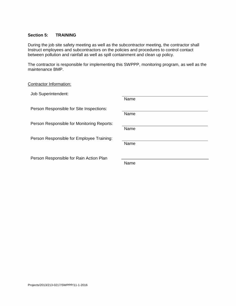
Section 5: TRAINING During the job site safety meeting as well as the subcontractor meeting, the contractor shall Instruct employees and subcontractors on the policies and procedures to control contact between pollution and rainfall as well as spill containment and clean up policy. The contractor is responsible for implementing this SWPPP, monitoring program, as well as the maintenance BMP. Contractor Information:
Job Superintendent:
Name Person Responsible for Site Inspections:
Name Person Responsible for Monitoring Reports:
Name Person Responsible for Employee Training:
Name Person Responsible for Rain Action Plan Name

Projects/2013/213-0217/SWPPP/11-1-2016
List of Sub-Contractors working on this Project
Projects/2013/213-0217/SWPPP/11-1-2016
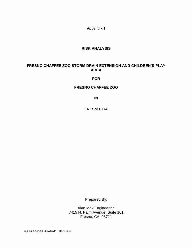
Appendix 1
RISK ANALYSIS
FRESNO CHAFFEE ZOO STORM DRAIN EXTENSION AND CHILDREN’S PLAY AREA
FOR
FRESNO CHAFFEE ZOO
IN
FRESNO, CA
Prepared By:
Alan Mok Engineering 7415 N. Palm Avenue, Suite 101
Fresno, CA 93711
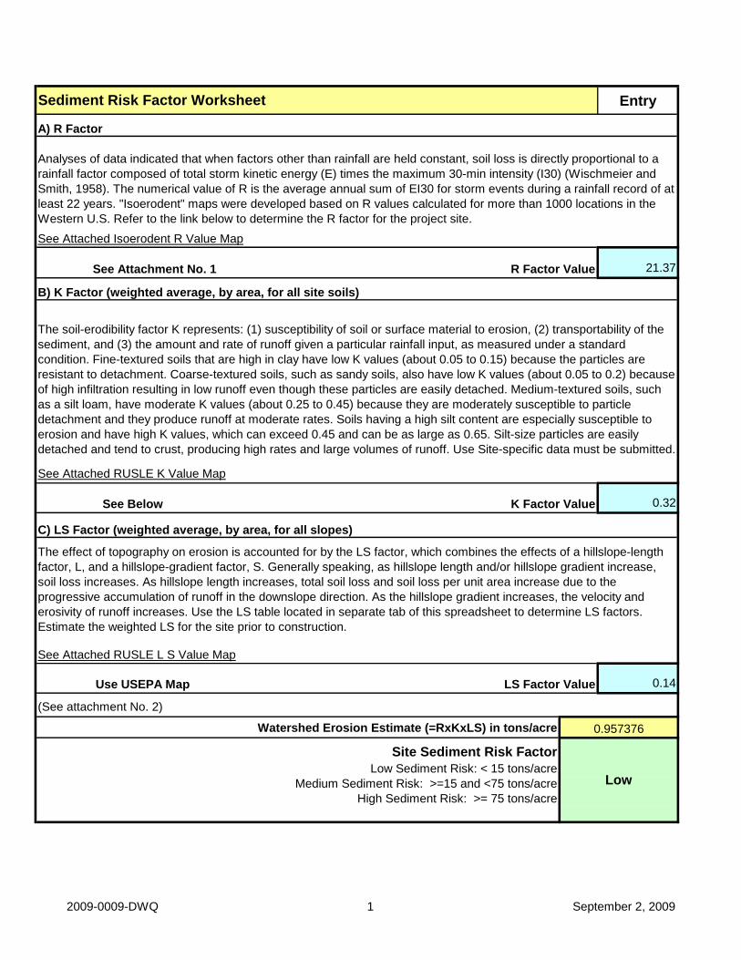
Entry
21.37
0.32
0.14
(See attachment No. 2)
Watershed Erosion Estimate (=RxKxLS) in tons/acre
Site Sediment Risk Factor
Low Sediment Risk: < 15 tons/acre
Medium Sediment Risk: >=15 and <75 tons/acre
High Sediment Risk: >= 75 tons/acre
See Below K Factor Value
Use USEPA Map LS Factor Value
Low
C) LS Factor (weighted average, by area, for all slopes)
The soil-erodibility factor K represents: (1) susceptibility of soil or surface material to erosion, (2) transportability of the
sediment, and (3) the amount and rate of runoff given a particular rainfall input, as measured under a standard
condition. Fine-textured soils that are high in clay have low K values (about 0.05 to 0.15) because the particles are
resistant to detachment. Coarse-textured soils, such as sandy soils, also have low K values (about 0.05 to 0.2) because
of high infiltration resulting in low runoff even though these particles are easily detached. Medium-textured soils, such
as a silt loam, have moderate K values (about 0.25 to 0.45) because they are moderately susceptible to particle
detachment and they produce runoff at moderate rates. Soils having a high silt content are especially susceptible to
erosion and have high K values, which can exceed 0.45 and can be as large as 0.65. Silt-size particles are easily
detached and tend to crust, producing high rates and large volumes of runoff. Use Site-specific data must be submitted.
The effect of topography on erosion is accounted for by the LS factor, which combines the effects of a hillslope-length
factor, L, and a hillslope-gradient factor, S. Generally speaking, as hillslope length and/or hillslope gradient increase,
soil loss increases. As hillslope length increases, total soil loss and soil loss per unit area increase due to the
progressive accumulation of runoff in the downslope direction. As the hillslope gradient increases, the velocity and
erosivity of runoff increases. Use the LS table located in separate tab of this spreadsheet to determine LS factors.
Estimate the weighted LS for the site prior to construction.
0.957376
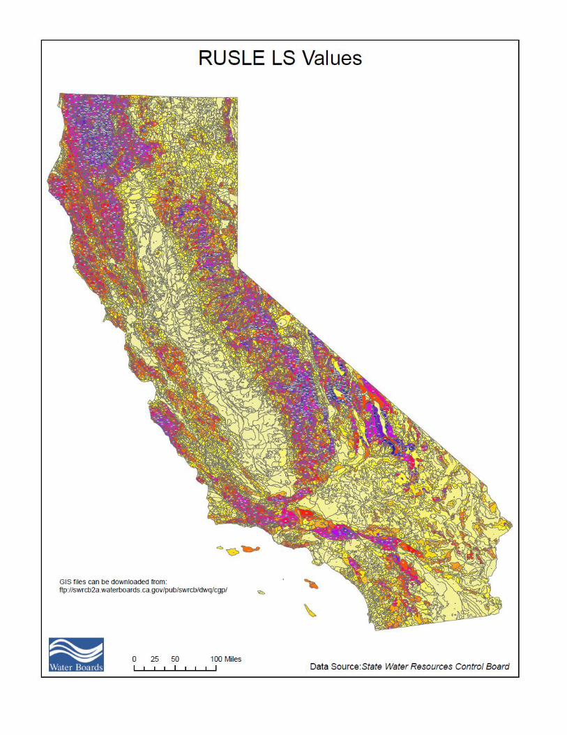
See Attached RUSLE K Value Map
See Attached RUSLE L S Value Map
Sediment Risk Factor Worksheet
A) R Factor
See Attachment No. 1 R Factor Value
B) K Factor (weighted average, by area, for all site soils)
Analyses of data indicated that when factors other than rainfall are held constant, soil loss is directly proportional to a
rainfall factor composed of total storm kinetic energy (E) times the maximum 30-min intensity (I30) (Wischmeier and
Smith, 1958). The numerical value of R is the average annual sum of EI30 for storm events during a rainfall record of at
least 22 years. "Isoerodent" maps were developed based on R values calculated for more than 1000 locations in the
Western U.S. Refer to the link below to determine the R factor for the project site.
See Attached Isoerodent R Value Map
2009-0009-DWQ 1 September 2, 2009

100
6 0
180
180
60
80
160
180
50
200
100
120
80
60
80
100
16 0
200
160
120
10
220
80
140
80
40
100
20
2 0 0
140
160
40
20
140180
100
80
120
120
60
60
160
40
80
40
100
60
80
100
100
120
120 60
60
40
40
20
20
20
10
10
10
80
80
80
6060
60
10
1010
10
20
20
20
20
20
40
40
40
40
40
40
Isoerodent R Value102040506080100120140160180200220 0 100 20050 Miles

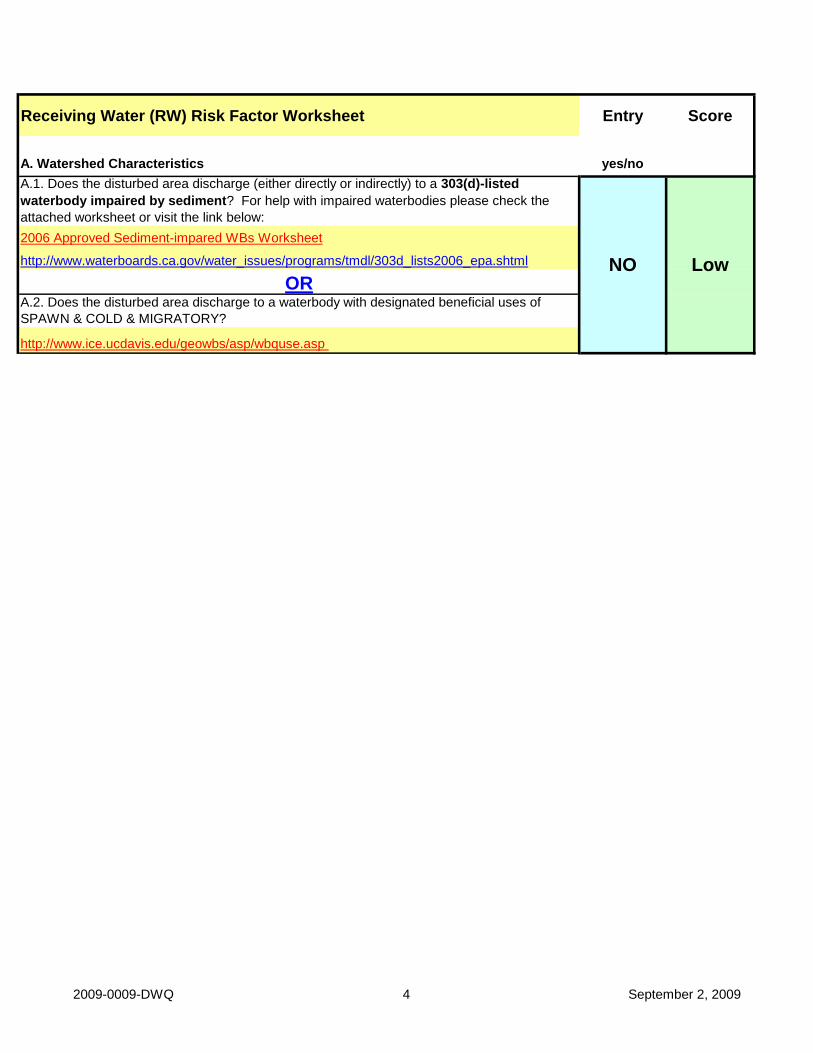
Receiving Water (RW) Risk Factor Worksheet Entry Score
A. Watershed Characteristics yes/no
A.1. Does the disturbed area discharge (either directly or indirectly) to a 303(d)-listed
waterbody impaired by sediment? For help with impaired waterbodies please check the
attached worksheet or visit the link below:
2006 Approved Sediment-impared WBs Worksheet
http://www.waterboards.ca.gov/water_issues/programs/tmdl/303d_lists2006_epa.shtml
ORA.2. Does the disturbed area discharge to a waterbody with designated beneficial uses of
SPAWN & COLD & MIGRATORY?
http://www.ice.ucdavis.edu/geowbs/asp/wbquse.asp
NO Low
2009-0009-DWQ 4 September 2, 2009

Low Medium High
Low Level 1
High Level 3
Project Sediment Risk: Low 1
Project RW Risk: Low 1
Project Combined Risk: Level 1
Combined Risk Level Matrix
Sediment Risk
Re
ce
ivin
g W
ate
r
Ris
k
Level 2
Level 2
2009-0009-DWQ
Attachment No. 3
5
September 2, 2009

Projects/2013/213-0217/SWPPP/11-1-2016
APPENDIX 2
Risk Level 1 Requirements
ATTACHMENT C
2009-0009-DWQ 1 September 2, 2009
ATTACHMENT C RISK LEVEL 1 REQUIREMENTS
A. Effluent Standards
[These requirements are the same as those in the General Permit order.]
1. Narrative – Risk Level 1 dischargers shall comply with the narrative
effluent standards listed below:
a. Storm water discharges and authorized non-storm water discharges regulated by this General Permit shall not contain a hazardous substance equal to or in excess of reportable quantities established in 40 C.F.R. §§ 117.3 and 302.4, unless a separate NPDES Permit has been issued to regulate those discharges.
b. Dischargers shall minimize or prevent pollutants in storm water
discharges and authorized non-storm water discharges through the use of controls, structures, and management practices that achieve BAT for toxic and non-conventional pollutants and BCT for conventional pollutants.
2. Numeric – Risk Level 1 dischargers are not subject to a numeric
effluent standard.
B. Good Site Management "Housekeeping" 1. Risk Level 1 dischargers shall implement good site management (i.e.,
"housekeeping") measures for construction materials that could potentially be a threat to water quality if discharged. At a minimum, Risk Level 1 dischargers shall implement the following good housekeeping measures: a. Conduct an inventory of the products used and/or expected to be
used and the end products that are produced and/or expected to be produced. This does not include materials and equipment that are designed to be outdoors and exposed to environmental conditions (i.e. poles, equipment pads, cabinets, conductors, insulators, bricks, etc.).
b. Cover and berm loose stockpiled construction materials that are not actively being used (i.e. soil, spoils, aggregate, fly-ash, stucco, hydrated lime, etc.).
ATTACHMENT C
2009-0009-DWQ 2 September 2, 2009
c. Store chemicals in watertight containers (with appropriate secondary containment to prevent any spillage or leakage) or in a storage shed (completely enclosed).
d. Minimize exposure of construction materials to precipitation. This
does not include materials and equipment that are designed to be outdoors and exposed to environmental conditions (i.e. poles, equipment pads, cabinets, conductors, insulators, bricks, etc.).
e. Implement BMPs to prevent the off-site tracking of loose
construction and landscape materials.
2. Risk Level 1 dischargers shall implement good housekeeping measures for waste management, which, at a minimum, shall consist of the following: a. Prevent disposal of any rinse or wash waters or materials on
impervious or pervious site surfaces or into the storm drain system.
b. Ensure the containment of sanitation facilities (e.g., portable toilets) to prevent discharges of pollutants to the storm water drainage system or receiving water.
c. Clean or replace sanitation facilities and inspecting them regularly
for leaks and spills.
d. Cover waste disposal containers at the end of every business day and during a rain event.
e. Prevent discharges from waste disposal containers to the storm
water drainage system or receiving water.
f. Contain and securely protect stockpiled waste material from wind and rain at all times unless actively being used.
g. Implement procedures that effectively address hazardous and non-
hazardous spills.
h. Develop a spill response and implementation element of the SWPPP prior to commencement of construction activities. The SWPPP shall require that: i. Equipment and materials for cleanup of spills shall be available
on site and that spills and leaks shall be cleaned up immediately and disposed of properly; and

ATTACHMENT C
2009-0009-DWQ 3 September 2, 2009
ii. Appropriate spill response personnel are assigned and trained.
i. Ensure the containment of concrete washout areas and other washout areas that may contain additional pollutants so there is no discharge into the underlying soil and onto the surrounding areas.
3. Risk Level 1 dischargers shall implement good housekeeping for
vehicle storage and maintenance, which, at a minimum, shall consist of the following: a. Prevent oil, grease, or fuel to leak in to the ground, storm drains or
surface waters.
b. Place all equipment or vehicles, which are to be fueled, maintained and stored in a designated area fitted with appropriate BMPs.
c. Clean leaks immediately and disposing of leaked materials
properly.
4. Risk Level 1 dischargers shall implement good housekeeping for landscape materials, which, at a minimum, shall consist of the following: a. Contain stockpiled materials such as mulches and topsoil when
they are not actively being used.
b. Contain fertilizers and other landscape materials when they are not actively being used.
c. Discontinue the application of any erodible landscape material within 2 days before a forecasted rain event or during periods of precipitation.
d. Apply erodible landscape material at quantities and application
rates according to manufacture recommendations or based on written specifications by knowledgeable and experienced field personnel.
e. Stack erodible landscape material on pallets and covering or
storing such materials when not being used or applied.
5. Risk Level 1 dischargers shall conduct an assessment and create a list of potential pollutant sources and identify any areas of the site where additional BMPs are necessary to reduce or prevent pollutants in storm water discharges and authorized non-storm water discharges. This potential pollutant list shall be kept with the SWPPP and shall identify
ATTACHMENT C
2009-0009-DWQ 4 September 2, 2009
all non-visible pollutants which are known, or should be known, to occur on the construction site. At a minimum, when developing BMPs, Risk Level 1 dischargers shall do the following:
a. Consider the quantity, physical characteristics (e.g., liquid, powder,
solid), and locations of each potential pollutant source handled, produced, stored, recycled, or disposed of at the site.
b. Consider the degree to which pollutants associated with those
materials may be exposed to and mobilized by contact with storm water.
c. Consider the direct and indirect pathways that pollutants may be
exposed to storm water or authorized non-storm water discharges. This shall include an assessment of past spills or leaks, non-storm water discharges, and discharges from adjoining areas.
d. Ensure retention of sampling, visual observation, and inspection
records.
e. Ensure effectiveness of existing BMPs to reduce or prevent pollutants in storm water discharges and authorized non-storm water discharges.
6. Risk Level 1 dischargers shall implement good housekeeping
measures on the construction site to control the air deposition of site materials and from site operations. Such particulates can include, but are not limited to, sediment, nutrients, trash, metals, bacteria, oil and grease and organics.
C. Non-Storm Water Management
1. Risk Level 1 dischargers shall implement measures to control all non-
storm water discharges during construction.
2. Risk Level 1 dischargers shall wash vehicles in such a manner as to prevent non-storm water discharges to surface waters or MS4 drainage systems.
3. Risk Level 1 dischargers shall clean streets in such a manner as to
prevent unauthorized non-storm water discharges from reaching surface water or MS4 drainage systems.
ATTACHMENT C
2009-0009-DWQ 5 September 2, 2009
D. Erosion Control 1. Risk Level 1 dischargers shall implement effective wind erosion
control.
2. Risk Level 1 dischargers shall provide effective soil cover for inactive1 areas and all finished slopes, open space, utility backfill, and completed lots.
3. Risk Level 1 dischargers shall limit the use of plastic materials when
more sustainable, environmentally friendly alternatives exist. Where plastic materials are deemed necessary, the discharger shall consider the use of plastic materials resistant to solar degradation.
E. Sediment Controls
1. Risk Level 1 dischargers shall establish and maintain effective
perimeter controls and stabilize all construction entrances and exits to sufficiently control erosion and sediment discharges from the site.
2. On sites where sediment basins are to be used, Risk Level 1 dischargers shall, at minimum, design sediment basins according to the method provided in CASQA’s Construction BMP Guidance Handbook.
F. Run-on and Runoff Controls
Risk Level 1 dischargers shall effectively manage all run-on, all runoff within the site and all runoff that discharges off the site. Run-on from off site shall be directed away from all disturbed areas or shall collectively be in compliance with the effluent limitations in this General Permit.
G. Inspection, Maintenance and Repair
1. Risk Level 1 dischargers shall ensure that all inspection, maintenance
repair and sampling activities at the project location shall be performed or supervised by a Qualified SWPPP Practitioner (QSP) representing the discharger. The QSP may delegate any or all of these activities to an employee trained to do the task(s) appropriately, but shall ensure adequate deployment.
2. Risk Level 1 dischargers shall perform weekly inspections and observations, and at least once each 24-hour period during extended
1 Inactive areas of construction are areas of construction activity that have been disturbed and are not scheduled to be re-disturbed for at least 14 days.

ATTACHMENT C
2009-0009-DWQ 6 September 2, 2009
storm events, to identify and record BMPs that need maintenance to operate effectively, that have failed, or that could fail to operate as intended. Inspectors shall be the QSP or be trained by the QSP.
3. Upon identifying failures or other shortcomings, as directed by the
QSP, Risk Level 1 dischargers shall begin implementing repairs or design changes to BMPs within 72 hours of identification and complete the changes as soon as possible.
4. For each inspection required, Risk Level 1 dischargers shall complete
an inspection checklist, using a form provided by the State Water Board or Regional Water Board or in an alternative format.
5. Risk Level 1 dischargers shall ensure that checklists shall remain onsite with the SWPPP and at a minimum, shall include:
a. Inspection date and date the inspection report was written.
b. Weather information, including presence or absence of
precipitation, estimate of beginning of qualifying storm event, duration of event, time elapsed since last storm, and approximate amount of rainfall in inches.
c. Site information, including stage of construction, activities
completed, and approximate area of the site exposed.
d. A description of any BMPs evaluated and any deficiencies noted.
e. If the construction site is safely accessible during inclement weather, list the observations of all BMPs: erosion controls, sediment controls, chemical and waste controls, and non-storm water controls. Otherwise, list the results of visual inspections at all relevant outfalls, discharge points, downstream locations and any projected maintenance activities.
f. Report the presence of noticeable odors or of any visible sheen on
the surface of any discharges.
g. Any corrective actions required, including any necessary changes to the SWPPP and the associated implementation dates.
h. Photographs taken during the inspection, if any.
i. Inspector’s name, title, and signature.

ATTACHMENT C
2009-0009-DWQ 7 September 2, 2009
H. Rain Event Action Plan Not required for Risk Level 1 dischargers.

ATTACHMENT C
2009-0009-DWQ 8 September 2, 2009
I. Risk Level 1 Monitoring and Reporting Requirements
Table 1- Summary of Monitoring Requirements
Visual Inspections Sample Collection Pre-storm
Event Risk Level
Quarterly Non-storm Water
Discharge
Baseline REAPDaily StormBMP
Post Storm
Storm Water
Discharge Receiving
Water
1 X X X X
1. Construction Site Monitoring Program Requirements
a. Pursuant to Water Code Sections 13383 and 13267, all dischargers subject to this General Permit shall develop and implement a written site-specific Construction Site Monitoring Program (CSMP) in accordance with the requirements of this Section. The CSMP shall include all monitoring procedures and instructions, location maps, forms, and checklists as required in this section. The CSMP shall be developed prior to the commencement of construction activities, and revised as necessary to reflect project revisions. The CSMP shall be a part of the Storm Water Pollution Prevention Plan (SWPPP), included as an appendix or separate SWPPP chapter.
b. Existing dischargers registered under the State Water Board Order
No. 99-08-DWQ shall make and implement necessary revisions to their Monitoring Programs to reflect the changes in this General Permit in a timely manner, but no later than July 1, 2010. Existing dischargers shall continue to implement their existing Monitoring Programs in compliance with State Water Board Order No. 99-08-DWQ until the necessary revisions are completed according to the schedule above.
c. When a change of ownership occurs for all or any portion of the
construction site prior to completion or final stabilization, the new discharger shall comply with these requirements as of the date the ownership change occurs.
2. Objectives
The CSMP shall be developed and implemented to address the following objectives:
a. To demonstrate that the site is in compliance with the Discharge
Prohibitions;

ATTACHMENT C
2009-0009-DWQ 9 September 2, 2009
b. To determine whether non-visible pollutants are present at the
construction site and are causing or contributing to exceedances of water quality objectives;
c. To determine whether immediate corrective actions, additional Best
Management Practice (BMP) implementation, or SWPPP revisions are necessary to reduce pollutants in storm water discharges and authorized non-storm water discharges; and
d. To determine whether BMPs included in the SWPPP are effective
in preventing or reducing pollutants in storm water discharges and authorized non-storm water discharges.
3. Risk Level 1 - Visual Monitoring (Inspection) Requirements for
Qualifying Rain Events
a. Risk Level 1 dischargers shall visually observe (inspect) storm water discharges at all discharge locations within two business days (48 hours) after each qualifying rain event.
b. Risk Level 1 dischargers shall visually observe (inspect) the
discharge of stored or contained storm water that is derived from and discharged subsequent to a qualifying rain event producing precipitation of ½ inch or more at the time of discharge. Stored or contained storm water that will likely discharge after operating hours due to anticipated precipitation shall be observed prior to the discharge during operating hours.
c. Risk Level 1 dischargers shall conduct visual observations
(inspections) during business hours only.
d. Risk Level 1 dischargers shall record the time, date and rain gauge reading of all qualifying rain events.
e. Within 2 business days (48 hours) prior to each qualifying rain
event, Risk Level 1 dischargers shall visually observe (inspect):
i. All storm water drainage areas to identify any spills, leaks, or uncontrolled pollutant sources. If needed, the discharger shall implement appropriate corrective actions.
ii. All BMPs to identify whether they have been properly
implemented in accordance with the SWPPP. If needed, the discharger shall implement appropriate corrective actions.

ATTACHMENT C
2009-0009-DWQ 10 September 2, 2009
iii. Any storm water storage and containment areas to detect leaks and ensure maintenance of adequate freeboard.
f. For the visual observations (inspections) described in e.i and e.iii
above, Risk Level 1 dischargers shall observe the presence or absence of floating and suspended materials, a sheen on the surface, discolorations, turbidity, odors, and source(s) of any observed pollutants.
g. Within two business days (48 hours) after each qualifying rain
event, Risk Level 1 dischargers shall conduct post rain event visual observations (inspections) to (1) identify whether BMPs were adequately designed, implemented, and effective, and (2) identify additional BMPs and revise the SWPPP accordingly.
h. Risk Level 1 dischargers shall maintain on-site records of all visual
observations (inspections), personnel performing the observations, observation dates, weather conditions, locations observed, and corrective actions taken in response to the observations.
4. Risk Level 1 – Visual Observation Exemptions
a. Risk Level 1 dischargers shall be prepared to conduct visual
observation (inspections) until the minimum requirements of Section I.3 above are completed. Risk Level 1 dischargers are not required to conduct visual observation (inspections) under the following conditions:
i. During dangerous weather conditions such as flooding and
electrical storms.
ii. Outside of scheduled site business hours. b. If no required visual observations (inspections) are collected due to
these exceptions, Risk Level 1 dischargers shall include an explanation in their SWPPP and in the Annual Report documenting why the visual observations (inspections) were not conducted.
5. Risk Level 1 – Monitoring Methods
Risk Level 1 dischargers shall include a description of the visual observation locations, visual observation procedures, and visual observation follow-up and tracking procedures in the CSMP.
6. Risk Level 1 – Non-Storm Water Discharge Monitoring Requirements
ATTACHMENT C
2009-0009-DWQ 11 September 2, 2009
a. Visual Monitoring Requirements:
i. Risk Level 1 dischargers shall visually observe (inspect) each
drainage area for the presence of (or indications of prior) unauthorized and authorized non-storm water discharges and their sources.
ii. Risk Level 1 dischargers shall conduct one visual observation
(inspection) quarterly in each of the following periods: January-March, April-June, July-September, and October-December. Visual observation (inspections) are only required during daylight hours (sunrise to sunset).
iii. Risk Level 1 dischargers shall ensure that visual observations
(inspections) document the presence or evidence of any non-storm water discharge (authorized or unauthorized), pollutant characteristics (floating and suspended material, sheen, discoloration, turbidity, odor, etc.), and source. Risk Level 1 dischargers shall maintain on-site records indicating the personnel performing the visual observation (inspections), the dates and approximate time each drainage area and non-storm water discharge was observed, and the response taken to eliminate unauthorized non-storm water discharges and to reduce or prevent pollutants from contacting non-storm water discharges.
7. Risk Level 1 – Non-Visible Pollutant Monitoring Requirements
a. Risk Level 1 dischargers shall collect one or more samples during
any breach, malfunction, leakage, or spill observed during a visual inspection which could result in the discharge of pollutants to surface waters that would not be visually detectable in storm water.
b. Risk Level 1 dischargers shall ensure that water samples are large
enough to characterize the site conditions.
c. Risk Level 1 dischargers shall collect samples at all discharge locations that can be safely accessed.
d. Risk Level 1 dischargers shall collect samples during the first two
hours of discharge from rain events that occur during business hours and which generate runoff.
e. Risk Level 1 dischargers shall analyze samples for all non-visible
pollutant parameters (if applicable) - parameters indicating the
ATTACHMENT C
2009-0009-DWQ 12 September 2, 2009
presence of pollutants identified in the pollutant source assessment required (Risk Level 1 dischargers shall modify their CSMPs to address these additional parameters in accordance with any updated SWPPP pollutant source assessment).
f. Risk Level 1 dischargers shall collect a sample of storm water that
has not come in contact with the disturbed soil or the materials stored or used on-site (uncontaminated sample) for comparison with the discharge sample.
g. Risk Level 1 dischargers shall compare the uncontaminated sample
to the samples of discharge using field analysis or through laboratory analysis.2
h. Risk Level 1 dischargers shall keep all field /or analytical data in the
SWPPP document.
8. Risk Level 1 – Particle Size Analysis for Project Risk Justification
Risk Level 1 dischargers justifying an alternative project risk shall report a soil particle size analysis used to determine the RUSLE K-Factor. ASTM D-422 (Standard Test Method for Particle-Size Analysis of Soils), as revised, shall be used to determine the percentages of sand, very fine sand, silt, and clay on the site.
9. Risk Level 1 – Records
Risk Level 1 dischargers shall retain records of all storm water monitoring information and copies of all reports (including Annual Reports) for a period of at least three years. Risk Level 1 dischargers shall retain all records on-site while construction is ongoing. These records include: a. The date, place, time of facility inspections, sampling, visual
observation (inspections), and/or measurements, including precipitation.
b. The individual(s) who performed the facility inspections, sampling,
visual observation (inspections), and or measurements. c. The date and approximate time of analyses.
d. The individual(s) who performed the analyses.
2 For laboratory analysis, all sampling, sample preservation, and analyses must be conducted according to test procedures under 40 CFR Part 136. Field discharge samples shall be collected and analyzed according to the specifications of the manufacturer of the sampling devices employed.

ATTACHMENT C
2009-0009-DWQ 13 September 2, 2009
e. A summary of all analytical results from the last three years, the
method detection limits and reporting units, and the analytical techniques or methods used.
f. Rain gauge readings from site inspections.
g. Quality assurance/quality control records and results. h. Non-storm water discharge inspections and visual observation
(inspections) and storm water discharge visual observation records (see Sections I.3 and I.6 above).
i. Visual observation and sample collection exception records (see
Section I.4 above).
j. The records of any corrective actions and follow-up activities that resulted from analytical results, visual observation (inspections), or inspections.
Projects/2013/213-0217/SWPPP/11-1-2016
APPENDIX 3 - Reporting
Rain Event Action Plan
Risk Level 1, 2, 3 Visual Inspection Field Log Sheets
Risk Level 2 Effluent Sampling field log sheets
Risk Level 3 Effluent Sampling field log sheets
Risk Level 3 Receiving Water Sampling Field Log Sheets
CASQA SWPPP Template 113 January 2011
Risk Level 1, 2, 3 Visual Inspection Field Log Sheet
Date and Time of Inspection: Report Date:
Inspection Type: □ Weekly □ Before
predicted rain
□ During
rain event
□
Following qualifying rain event
□ Contained
stormwater release
□ Quarterly
non-stormwater
Site Information
Construction Site Name:
Construction stage and completed activities:
Approximate area of exposed site:
Weather and Observations
Date Rain Predicted to Occur: Predicted % chance of rain:
Estimate storm beginning:
(date and time)
Estimate storm duration:_________
(hours)
Estimate time since last storm: ________
(days or hours)
Rain gauge reading: _______
(inches)
Observations: If yes identify location
Odors Yes □ No □
Floating material Yes □ No □
Suspended Material Yes □ No □
Sheen Yes □ No □
Discolorations Yes □ No □
Turbidity Yes □ No □
Site Inspections
Outfalls or BMPs Evaluated Deficiencies Noted
(add additional sheets or attached detailed BMP Inspection Checklists)
Photos Taken: Yes □ No □ Photo Reference IDs:
Corrective Actions Identified (note if SWPPP/REAP change is needed)
Inspector Information
Inspector Name: Inspector Title:
Signature: Date:

CASQA SWPPP Template 114 January 2011
Risk Level 2 Effluent Sampling Field Log Sheets
Construction Site Name: Date: Time Start:
Sampler:
Sampling Event Type: □ Stormwater □ Non-stormwater □ Non-visible pollutant
Field Meter Calibration
pH Meter ID No./Desc.: Calibration Date/Time:
Turbidity Meter ID No./Desc.: Calibration Date/Time:
Field pH and Turbidity Measurements
Discharge Location Description pH Turbidity Time
Grab Samples Collected
Discharge Location Description Sample Type Time
Additional Sampling Notes:
Time End:
CASQA SWPPP Template 115 January 2011
Risk Level 3 Effluent Sampling Field Log Sheets
Construction Site Name: Date: Time Start:
Sampler:
Sampling Event Type: □ Stormwater □ Non-stormwater □ Non-visible
pollutant
□ Post NEL
Exceedance
Field Meter Calibration
pH Meter ID No./Desc.: Calibration Date/Time:
Turbidity Meter ID No./Desc.: Calibration Date/Time:
Field pH and Turbidity Measurements
Discharge Location Description pH Turbidity Time
Grab Samples Collected
Discharge Location Description SSC Other (specify) Time
Additional Sampling Notes:
Time End:
CASQA SWPPP Template 116 January 2011
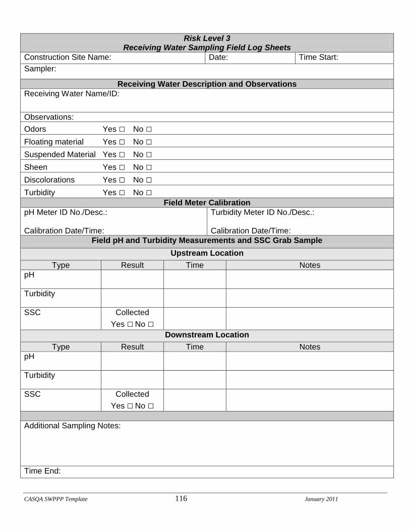
Risk Level 3 Receiving Water Sampling Field Log Sheets
Construction Site Name: Date: Time Start:
Sampler:
Receiving Water Description and Observations
Receiving Water Name/ID:
Observations:
Odors Yes □ No □
Floating material Yes □ No □
Suspended Material Yes □ No □
Sheen Yes □ No □
Discolorations Yes □ No □
Turbidity Yes □ No □
Field Meter Calibration
pH Meter ID No./Desc.: Calibration Date/Time:
Turbidity Meter ID No./Desc.: Calibration Date/Time:
Field pH and Turbidity Measurements and SSC Grab Sample
Upstream Location
Type Result Time Notes
pH
Turbidity
SSC Collected
Yes □ No □
Downstream Location
Type Result Time Notes
pH
Turbidity
SSC Collected
Yes □ No □
Additional Sampling Notes:
Time End:

CASQA SWPPP Template 117 January 2011
NAL or NEL Exceedance Evaluation Summary Report Page __ of __
Project Name
Project WDID
Project Location
Date of Exceedance
Type of Exceedance
NAL Daily Average pH Turbidity
NEL Daily Average pH Turbidity
Other (specify)
Measurement or Analytical Method
Field meter
(Sensitivity: )
Lab method (specify)
(Reporting Limit: )
(MDL: )
Calculated Daily Average
pH pH units
Turbidity NTU
Rain Gauge Measurement
inches
Compliance Storm Event
inches (5-year, 24-hour event)
Visual Observations on Day of Exceedance

CASQA SWPPP Template 118 January 2011
NAL or NEL Exceedance Evaluation Summary Report Page __ of __
Description of BMPs in Place at Time of Event
Initial Assessment of Cause
Corrective Actions Taken (deployed after exceedance)
Additional Corrective Actions Proposed
Report Completed By
(Print Name, Title)
Signature
CASQA SWPPP Template 119 January2011
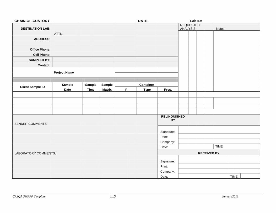
CHAIN-OF-CUSTODY
DATE:
Lab ID:
DESTINATION LAB: REQUESTED ANALYSIS Notes:
ATTN:
ADDRESS:
Office Phone:
Cell Phone:
SAMPLED BY:
Contact:
Project Name
Client Sample ID Sample Sample Sample Container
Date Time Matrix # Type Pres.
SENDER COMMENTS:
RELINQUISHED BY
Signature:
Print:
Company:
Date: TIME:
LABORATORY COMMENTS: RECEIVED BY
Signature:
Print:
Company:
Date: TIME:

Projects/2013/213-0217/SWPPP/11-1-2016
APPENDIX 4
BMP Fact Sheet
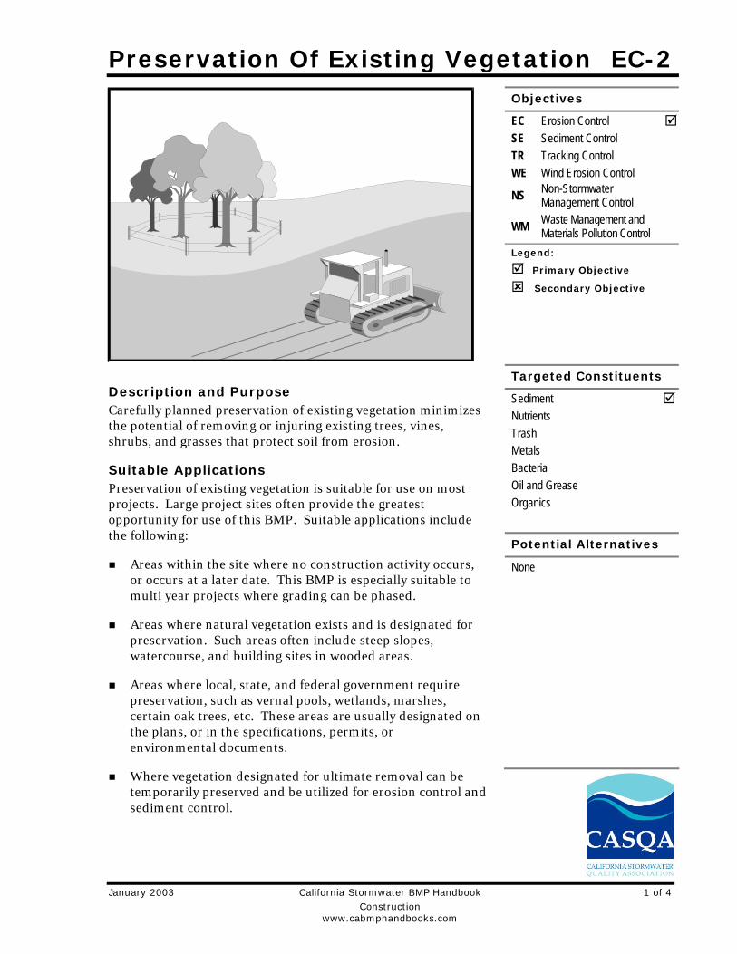
Preservation Of Existing Vegetation EC-2
January 2003 California Stormwater BMP Handbook 1 of 4 Construction www.cabmphandbooks.com
Description and Purpose Carefully planned preservation of existing vegetation minimizes the potential of removing or injuring existing trees, vines, shrubs, and grasses that protect soil from erosion.
Suitable Applications Preservation of existing vegetation is suitable for use on most projects. Large project sites often provide the greatest opportunity for use of this BMP. Suitable applications include the following:
Areas within the site where no construction activity occurs, or occurs at a later date. This BMP is especially suitable to multi year projects where grading can be phased.
Areas where natural vegetation exists and is designated for preservation. Such areas often include steep slopes, watercourse, and building sites in wooded areas.
Areas where local, state, and federal government require preservation, such as vernal pools, wetlands, marshes, certain oak trees, etc. These areas are usually designated on the plans, or in the specifications, permits, or environmental documents.
Where vegetation designated for ultimate removal can be temporarily preserved and be utilized for erosion control and sediment control.
Objectives
EC Erosion Control SE Sediment Control TR Tracking Control WE Wind Erosion Control
NS Non-Stormwater Management Control
WM Waste Management and Materials Pollution Control
Legend:
Primary Objective
Secondary Objective
Targeted Constituents
Sediment Nutrients Trash Metals Bacteria Oil and Grease Organics
Potential Alternatives
None
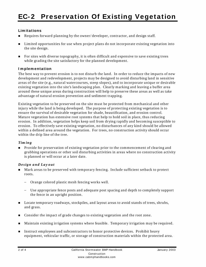
EC-2 Preservation Of Existing Vegetation
2 of 4 California Stormwater BMP Handbook January 2003 Construction www.cabmphandbooks.com
Limitations Requires forward planning by the owner/developer, contractor, and design staff.
Limited opportunities for use when project plans do not incorporate existing vegetation into the site design.
For sites with diverse topography, it is often difficult and expensive to save existing trees while grading the site satisfactory for the planned development.
Implementation The best way to prevent erosion is to not disturb the land. In order to reduce the impacts of new development and redevelopment, projects may be designed to avoid disturbing land in sensitive areas of the site (e.g., natural watercourses, steep slopes), and to incorporate unique or desirable existing vegetation into the site’s landscaping plan. Clearly marking and leaving a buffer area around these unique areas during construction will help to preserve these areas as well as take advantage of natural erosion prevention and sediment trapping.
Existing vegetation to be preserved on the site must be protected from mechanical and other injury while the land is being developed. The purpose of protecting existing vegetation is to ensure the survival of desirable vegetation for shade, beautification, and erosion control. Mature vegetation has extensive root systems that help to hold soil in place, thus reducing erosion. In addition, vegetation helps keep soil from drying rapidly and becoming susceptible to erosion. To effectively save existing vegetation, no disturbances of any kind should be allowed within a defined area around the vegetation. For trees, no construction activity should occur within the drip line of the tree.
Timing Provide for preservation of existing vegetation prior to the commencement of clearing and
grubbing operations or other soil disturbing activities in areas where no construction activity is planned or will occur at a later date.
Design and Layout Mark areas to be preserved with temporary fencing. Include sufficient setback to protect
roots.
− Orange colored plastic mesh fencing works well.
− Use appropriate fence posts and adequate post spacing and depth to completely support the fence in an upright position.
Locate temporary roadways, stockpiles, and layout areas to avoid stands of trees, shrubs, and grass.
Consider the impact of grade changes to existing vegetation and the root zone.
Maintain existing irrigation systems where feasible. Temporary irrigation may be required.
Instruct employees and subcontractors to honor protective devices. Prohibit heavy equipment, vehicular traffic, or storage of construction materials within the protected area.
Preservation Of Existing Vegetation EC-2
January 2003 California Stormwater BMP Handbook 3 of 4 Construction www.cabmphandbooks.com
Costs There is little cost associated with preserving existing vegetation if properly planned during the project design, and these costs may be offset by aesthetic benefits that enhance property values. During construction, the cost for preserving existing vegetation will likely be less than the cost of applying erosion and sediment controls to the disturbed area. Replacing vegetation inadvertently destroyed during construction can be extremely expensive, sometimes in excess of $10,000 per tree.
Inspection and Maintenance During construction, the limits of disturbance should remain clearly marked at all times. Irrigation or maintenance of existing vegetation should be described in the landscaping plan. If damage to protected trees still occurs, maintenance guidelines described below should be followed:
Verify that protective measures remain in place. Restore damaged protection measures immediately.
Serious tree injuries shall be attended to by an arborist.
Damage to the crown, trunk, or root system of a retained tree shall be repaired immediately.
Trench as far from tree trunks as possible, usually outside of the tree drip line or canopy. Curve trenches around trees to avoid large roots or root concentrations. If roots are encountered, consider tunneling under them. When trenching or tunneling near or under trees to be retained, place tunnels at least 18 in. below the ground surface, and not below the tree center to minimize impact on the roots.
Do not leave tree roots exposed to air. Cover exposed roots with soil as soon as possible. If soil covering is not practical, protect exposed roots with wet burlap or peat moss until the tunnel or trench is ready for backfill.
Cleanly remove the ends of damaged roots with a smooth cut.
Fill trenches and tunnels as soon as possible. Careful filling and tamping will eliminate air spaces in the soil, which can damage roots.
If bark damage occurs, cut back all loosened bark into the undamaged area, with the cut tapered at the top and bottom and drainage provided at the base of the wood. Limit cutting the undamaged area as much as possible.
Aerate soil that has been compacted over a trees root zone by punching holes 12 in. deep with an iron bar, and moving the bar back and forth until the soil is loosened. Place holes 18 in. apart throughout the area of compacted soil under the tree crown.
Fertilization
− Fertilize stressed or damaged broadleaf trees to aid recovery.
− Fertilize trees in the late fall or early spring.
EC-2 Preservation Of Existing Vegetation
4 of 4 California Stormwater BMP Handbook January 2003 Construction www.cabmphandbooks.com
- Apply fertilizer to the soil over the feeder roots and in accordance with label instructions, but never closer than 3 ft to the trunk. Increase the fertilized area by one-fourth of the crown area for conifers that have extended root systems.
Retain protective measures until all other construction activity is complete to avoid damage during site cleanup and stabilization.
References County of Sacramento Tree Preservation Ordinance, September 1981.
Stormwater Quality Handbooks Construction Site Best Management Practices (BMPs) Manual, State of California Department of Transportation (Caltrans), November 2000.
Stormwater Management of the Puget Sound Basin, Technical Manual, Publication #91-75, Washington State Department of Ecology, February 1992.
Water Quality Management Plan for The Lake Tahoe Region, Volume II, Handbook of Management Practices, Tahoe Regional Planning Agency, November 1988.
Hydroseeding EC-4
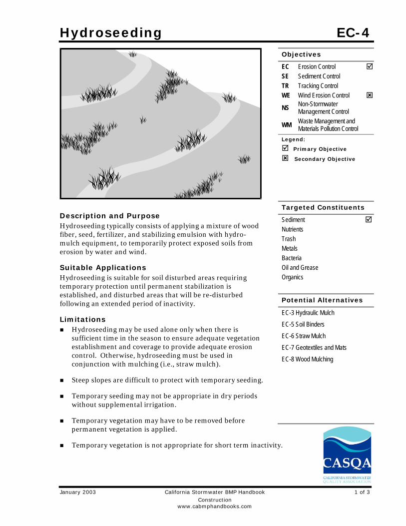
January 2003 California Stormwater BMP Handbook 1 of 3 Construction www.cabmphandbooks.com
Description and Purpose Hydroseeding typically consists of applying a mixture of wood fiber, seed, fertilizer, and stabilizing emulsion with hydro-mulch equipment, to temporarily protect exposed soils from erosion by water and wind.
Suitable Applications Hydroseeding is suitable for soil disturbed areas requiring temporary protection until permanent stabilization is established, and disturbed areas that will be re-disturbed following an extended period of inactivity.
Limitations Hydroseeding may be used alone only when there is
sufficient time in the season to ensure adequate vegetation establishment and coverage to provide adequate erosion control. Otherwise, hydroseeding must be used in conjunction with mulching (i.e., straw mulch).
Steep slopes are difficult to protect with temporary seeding.
Temporary seeding may not be appropriate in dry periods without supplemental irrigation.
Temporary vegetation may have to be removed before permanent vegetation is applied.
Temporary vegetation is not appropriate for short term inactivity.
Objectives
EC Erosion Control SE Sediment Control TR Tracking Control WE Wind Erosion Control
NS Non-Stormwater Management Control
WM Waste Management and Materials Pollution Control
Legend:
Primary Objective
Secondary Objective
Targeted Constituents
Sediment Nutrients Trash Metals Bacteria Oil and Grease Organics
Potential Alternatives
EC-3 Hydraulic Mulch
EC-5 Soil Binders
EC-6 Straw Mulch
EC-7 Geotextiles and Mats
EC-8 Wood Mulching
EC-4 Hydroseeding
2 of 3 California Stormwater BMP Handbook January 2003 Construction www.cabmphandbooks.com
Implementation In order to select appropriate hydroseeding mixtures, an evaluation of site conditions shall be performed with respect to:
- Soil conditions - Maintenance requirements
- Site topography - Sensitive adjacent areas
- Season and climate - Water availability
- Vegetation types - Plans for permanent vegetation
The local office of the U.S.D.A. Natural Resources Conservation Service (NRCS) is an excellent source of information on appropriate seed mixes.
The following steps shall be followed for implementation:
Avoid use of hydroseeding in areas where the BMP would be incompatible with future earthwork activities and would have to be removed.
Hydroseeding can be accomplished using a multiple step or one step process. The multiple step process ensures maximum direct contact of the seeds to soil. When the one step process is used to apply the mixture of fiber, seed, etc., the seed rate shall be increased to compensate for all seeds not having direct contact with the soil.
Prior to application, roughen the area to be seeded with the furrows trending along the contours.
Apply a straw mulch to keep seeds in place and to moderate soil moisture and temperature until the seeds germinate and grow.
All seeds shall be in conformance with the California State Seed Law of the Department of Agriculture. Each seed bag shall be delivered to the site sealed and clearly marked as to species, purity, percent germination, dealer's guarantee, and dates of test. The container shall be labeled to clearly reflect the amount of Pure Live Seed (PLS) contained. All legume seed shall be pellet inoculated. Inoculant sources shall be species specific and shall be applied at a rate of 2 lb of inoculant per 100 lb seed.
Commercial fertilizer shall conform to the requirements of the California Food and Agricultural Code. Fertilizer shall be pelleted or granular form.
Follow up applications shall be made as needed to cover weak spots and to maintain adequate soil protection.
Avoid over spray onto roads, sidewalks, drainage channels, existing vegetation, etc.
Costs Average cost for installation and maintenance may vary from as low as $300 per acre for flat slopes and stable soils, to $1600 per acre for moderate to steep slopes and/or erosive soils.
Hydroseeding EC-4
January 2003 California Stormwater BMP Handbook 3 of 3 Construction www.cabmphandbooks.com
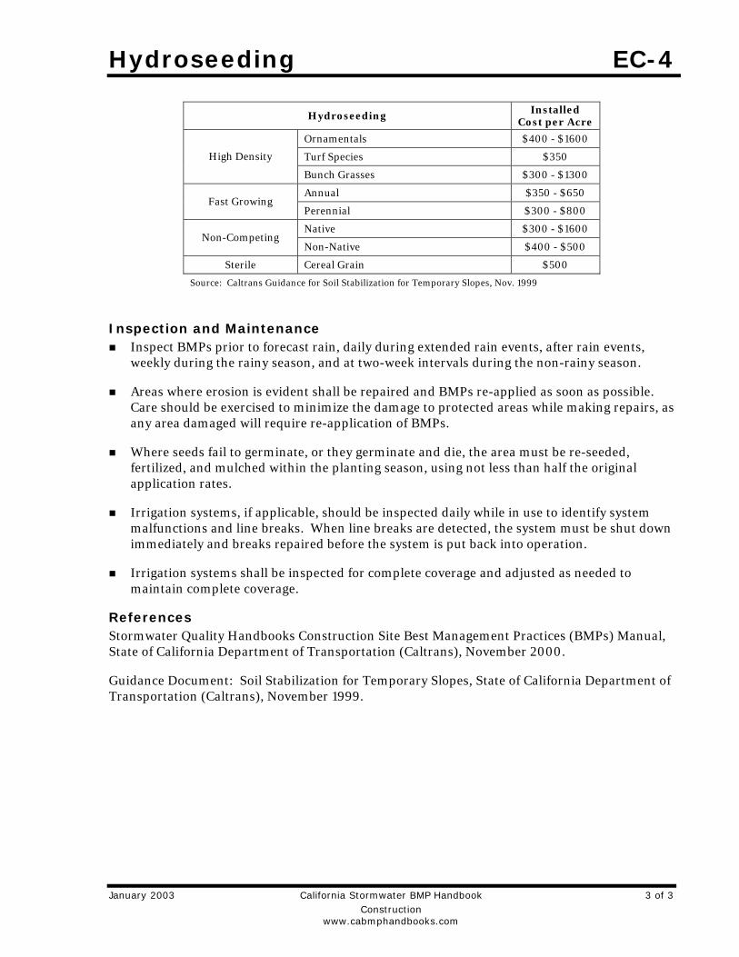
Hydroseeding Installed Cost per Acre
Ornamentals $400 - $1600
Turf Species $350 High Density
Bunch Grasses $300 - $1300
Annual $350 - $650 Fast Growing
Perennial $300 - $800
Native $300 - $1600 Non-Competing
Non-Native $400 - $500
Sterile Cereal Grain $500
Source: Caltrans Guidance for Soil Stabilization for Temporary Slopes, Nov. 1999
Inspection and Maintenance Inspect BMPs prior to forecast rain, daily during extended rain events, after rain events,
weekly during the rainy season, and at two-week intervals during the non-rainy season.
Areas where erosion is evident shall be repaired and BMPs re-applied as soon as possible. Care should be exercised to minimize the damage to protected areas while making repairs, as any area damaged will require re-application of BMPs.
Where seeds fail to germinate, or they germinate and die, the area must be re-seeded, fertilized, and mulched within the planting season, using not less than half the original application rates.
Irrigation systems, if applicable, should be inspected daily while in use to identify system malfunctions and line breaks. When line breaks are detected, the system must be shut down immediately and breaks repaired before the system is put back into operation.
Irrigation systems shall be inspected for complete coverage and adjusted as needed to maintain complete coverage.
References Stormwater Quality Handbooks Construction Site Best Management Practices (BMPs) Manual, State of California Department of Transportation (Caltrans), November 2000.
Guidance Document: Soil Stabilization for Temporary Slopes, State of California Department of Transportation (Caltrans), November 1999.
Geotextiles and Mats EC-7
January 2003 California Stormwater BMP Handbook 1 of 11 Construction www.cabmphandbooks.com
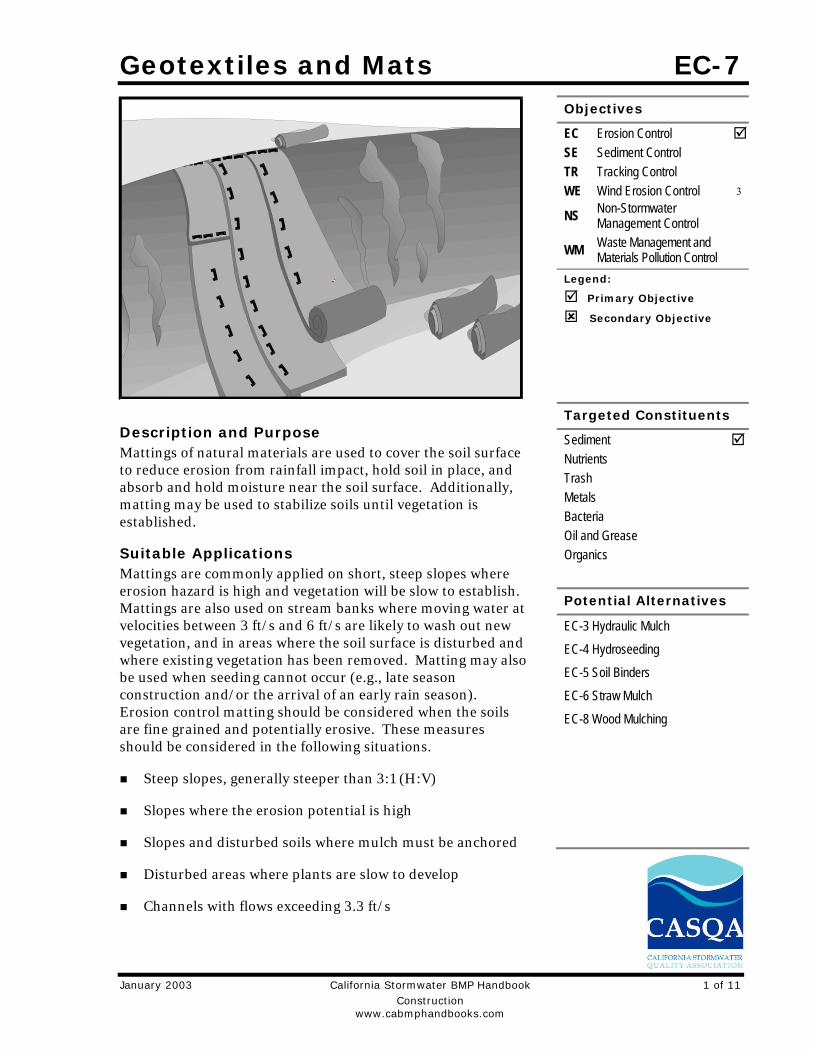
Description and Purpose Mattings of natural materials are used to cover the soil surface to reduce erosion from rainfall impact, hold soil in place, and absorb and hold moisture near the soil surface. Additionally, matting may be used to stabilize soils until vegetation is established.
Suitable Applications Mattings are commonly applied on short, steep slopes where erosion hazard is high and vegetation will be slow to establish. Mattings are also used on stream banks where moving water at velocities between 3 ft/s and 6 ft/s are likely to wash out new vegetation, and in areas where the soil surface is disturbed and where existing vegetation has been removed. Matting may also be used when seeding cannot occur (e.g., late season construction and/or the arrival of an early rain season). Erosion control matting should be considered when the soils are fine grained and potentially erosive. These measures should be considered in the following situations.
Steep slopes, generally steeper than 3:1 (H:V)
Slopes where the erosion potential is high
Slopes and disturbed soils where mulch must be anchored
Disturbed areas where plants are slow to develop
Channels with flows exceeding 3.3 ft/s
Objectives
EC Erosion Control SE Sediment Control TR Tracking Control WE Wind Erosion Control 3
NS Non-Stormwater Management Control
WM Waste Management and Materials Pollution Control
Legend:
Primary Objective
Secondary Objective
Targeted Constituents
Sediment Nutrients Trash Metals Bacteria Oil and Grease Organics
Potential Alternatives
EC-3 Hydraulic Mulch
EC-4 Hydroseeding
EC-5 Soil Binders
EC-6 Straw Mulch
EC-8 Wood Mulching
EC-7 Geotextiles and Mats
2 of 11 California Stormwater BMP Handbook January 2003 Construction www.cabmphandbooks.com
Channels to be vegetated
Stockpiles
Slopes adjacent to water bodies of Environmentally Sensitive Areas (ESAs)
Limitations Properly installed mattings provide excellent erosion control but do so at relatively high cost.
This high cost typically limits the use of mattings to areas of concentrated channel flow and steep slopes.
Mattings are more costly than other BMP practices, limiting their use to areas where other BMPs are ineffective (e.g. channels, steep slopes).
Installation is critical and requires experienced contractors. The contractor should install the matting material in such a manner that continuous contact between the material and the soil occurs.
Geotextiles and Mats may delay seed germination, due to reduction in soil temperature.
Blankets and mats are generally not suitable for excessively rocky sites or areas where the final vegetation will be mowed (since staples and netting can catch in mowers).
Blankets and mats must be removed and disposed of prior to application of permanent soil stabilization measures.
Plastic sheeting is easily vandalized, easily torn, photodegradable, and must be disposed of at a landfill.
Plastic results in 100% runoff, which may cause serious erosion problems in the areas receiving the increased flow.
The use of plastic should be limited to covering stockpiles or very small graded areas for short periods of time (such as through one imminent storm event) until alternative measures, such as seeding and mulching, may be installed.
Geotextiles, mats, plastic covers, and erosion control covers have maximum flow rate limitations; consult the manufacturer for proper selection.
Not suitable for areas that have heavy foot traffic (tripping hazard) – e.g., pad areas around buildings under construction.
Implementation Material Selection Organic matting materials have been found to be effective where re-vegetation will be provided by re-seeding. The choice of matting should be based on the size of area, side slopes, surface conditions such as hardness, moisture, weed growth, and availability of materials.
Geotextiles and Mats EC-7
January 2003 California Stormwater BMP Handbook 3 of 11 Construction www.cabmphandbooks.com
The following natural and synthetic mattings are commonly used:
Geotextiles Material should be a woven polypropylene fabric with minimum thickness of 0.06 in.,
minimum width of 12 ft and should have minimum tensile strength of 150 lbs (warp), 80 lbs (fill) in conformance with the requirements in ASTM Designation: D 4632. The permittivity of the fabric should be approximately 0.07 sec–1 in conformance with the requirements in ASTM Designation: D4491. The fabric should have an ultraviolet (UV) stability of 70 percent in conformance with the requirements in ASTM designation: D4355. Geotextile blankets must be secured in place with wire staples or sandbags and by keying into tops of slopes to prevent infiltration of surface waters under geotextile. Staples should be made of minimum 11 gauge steel wire and should be U-shaped with 8 in. legs and 2 in. crown.
Geotextiles may be reused if they are suitable for the use intended.
Plastic Covers Plastic sheeting should have a minimum thickness of 6 mils, and must be keyed in at the top
of slope and firmly held in place with sandbags or other weights placed no more than 10 ft apart. Seams are typically taped or weighted down their entire length, and there should be at least a 12 in. to 24 in. overlap of all seams. Edges should be embedded a minimum of 6 in. in soil.
All sheeting must be inspected periodically after installation and after significant rainstorms to check for erosion, undermining, and anchorage failure. Any failures must be repaired immediately. If washout or breakages occur, the material should be re-installed after repairing the damage to the slope.
Erosion Control Blankets/Mats Biodegradable rolled erosion control products (RECPs) are typically composed of jute fibers,
curled wood fibers, straw, coconut fiber, or a combination of these materials. In order for an RECP to be considered 100% biodegradable, the netting, sewing or adhesive system that holds the biodegradable mulch fibers together must also be biodegradable.
- Jute is a natural fiber that is made into a yarn that is loosely woven into a biodegradable mesh. It is designed to be used in conjunction with vegetation and has longevity of approximately one year. The material is supplied in rolled strips, which should be secured to the soil with U-shaped staples or stakes in accordance with manufacturers’ recommendations.
- Excelsior (curled wood fiber) blanket material should consist of machine produced mats of curled wood excelsior with 80 percent of the fiber 6 in. or longer. The excelsior blanket should be of consistent thickness. The wood fiber must be evenly distributed over the entire area of the blanket. The top surface of the blanket should be covered with a photodegradable extruded plastic mesh. The blanket should be smolder resistant without the use of chemical additives and should be non-toxic and non-injurious to plant and animal life. Excelsior blankets should be furnished in rolled strips, a minimum of 48 in. wide, and should have an average weight of 0.8 lb/yd2, ±10 percent, at the time of manufacture. Excelsior blankets must be secured in place with wire staples. Staples

EC-7 Geotextiles and Mats
4 of 11 California Stormwater BMP Handbook January 2003 Construction www.cabmphandbooks.com
should be made of minimum 11 gauge steel wire and should be U-shaped with 8 in. legs and 2 in. crown.
- Straw blanket should be machine produced mats of straw with a lightweight biodegradable netting top layer. The straw should be attached to the netting with biodegradable thread or glue strips. The straw blanket should be of consistent thickness. The straw should be evenly distributed over the entire area of the blanket. Straw blanket should be furnished in rolled strips a minimum of 6.5 ft wide, a minimum of 80 ft long and a minimum of 0.5 lb/yd2. Straw blankets must be secured in place with wire staples. Staples should be made of minimum 11 gauge steel wire and should be U-shaped with 8 in. legs and 2 in. crown.
- Wood fiber blanket is composed of biodegradable fiber mulch with extruded plastic netting held together with adhesives. The material is designed to enhance re-vegetation. The material is furnished in rolled strips, which must be secured to the ground with U-shaped staples or stakes in accordance with manufacturers’ recommendations.
- Coconut fiber blanket should be a machine produced mat of 100 percent coconut fiber with biodegradable netting on the top and bottom. The coconut fiber should be attached to the netting with biodegradable thread or glue strips. The coconut fiber blanket should be of consistent thickness. The coconut fiber should be evenly distributed over the entire area of the blanket. Coconut fiber blanket should be furnished in rolled strips with a minimum of 6.5 ft wide, a minimum of 80 ft. long and a minimum of 0.5 lb/yd2. Coconut fiber blankets must be secured in place with wire staples. Staples should be made of minimum 11 gauge steel wire and should be U-shaped with 8 in. legs and 2 in. crown.
- Coconut fiber mesh is a thin permeable membrane made from coconut or corn fiber that is spun into a yarn and woven into a biodegradable mat. It is designed to be used in conjunction with vegetation and typically has longevity of several years. The material is supplied in rolled strips, which must be secured to the soil with U-shaped staples or stakes in accordance with manufacturers’ recommendations.
- Straw coconut fiber blanket should be machine produced mats of 70 percent straw and 30 percent coconut fiber with a biodegradable netting top layer and a biodegradable bottom net. The straw and coconut fiber should be attached to the netting with biodegradable thread or glue strips. The straw coconut fiber blanket should be of consistent thickness. The straw and coconut fiber should be evenly distributed over the entire area of the blanket. Straw coconut fiber blanket should be furnished in rolled strips a minimum of 6.5 ft wide, a minimum of 80 ft long and a minimum of 0.5 lb/yd2. Straw coconut fiber blankets must be secured in place with wire staples. Staples should be made of minimum 11 gauge steel wire and should be U-shaped with 8 in. legs and 2 in. crown.
Non-biodegradable RECPs are typically composed of polypropylene, polyethylene, nylon or other synthetic fibers. In some cases, a combination of biodegradable and synthetic fibers is used to construct the RECP. Netting used to hold these fibers together is typically non-biodegradable as well.
Geotextiles and Mats EC-7
January 2003 California Stormwater BMP Handbook 5 of 11 Construction www.cabmphandbooks.com
- Plastic netting is a lightweight biaxially oriented netting designed for securing loose mulches like straw or paper to soil surfaces to establish vegetation. The netting is photodegradable. The netting is supplied in rolled strips, which must be secured with U-shaped staples or stakes in accordance with manufacturers’ recommendations.
- Plastic mesh is an open weave geotextile that is composed of an extruded synthetic fiber woven into a mesh with an opening size of less than ¼ in. It is used with re-vegetation or may be used to secure loose fiber such as straw to the ground. The material is supplied in rolled strips, which must be secured to the soil with U-shaped staples or stakes in accordance with manufacturers’ recommendations.
- Synthetic fiber with netting is a mat that is composed of durable synthetic fibers treated to resist chemicals and ultraviolet light. The mat is a dense, three dimensional mesh of synthetic (typically polyolefin) fibers stitched between two polypropylene nets. The mats are designed to be re-vegetated and provide a permanent composite system of soil, roots, and geomatrix. The material is furnished in rolled strips, which must be secured with U-shaped staples or stakes in accordance with manufacturers’ recommendations.
- Bonded synthetic fibers consist of a three dimensional geomatrix nylon (or other synthetic) matting. Typically it has more than 90 percent open area, which facilitates root growth. It’s tough root reinforcing system anchors vegetation and protects against hydraulic lift and shear forces created by high volume discharges. It can be installed over prepared soil, followed by seeding into the mat. Once vegetated, it becomes an invisible composite system of soil, roots, and geomatrix. The material is furnished in rolled strips that must be secured with U-shaped staples or stakes in accordance with manufacturers’ recommendations.
- Combination synthetic and biodegradable RECPs consist of biodegradable fibers, such as wood fiber or coconut fiber, with a heavy polypropylene net stitched to the top and a high strength continuous filament geomatrix or net stitched to the bottom. The material is designed to enhance re-vegetation. The material is furnished in rolled strips, which must be secured with U-shaped staples or stakes in accordance with manufacturers’ recommendations.
Site Preparation Proper site preparation is essential to ensure complete contact of the blanket or matting with
the soil.
Grade and shape the area of installation.
Remove all rocks, clods, vegetation or other obstructions so that the installed blankets or mats will have complete, direct contact with the soil.
Prepare seedbed by loosening 2 to 3 in. of topsoil.
Seeding Seed the area before blanket installation for erosion control and revegetation. Seeding after mat installation is often specified for turf reinforcement application. When seeding prior to blanket
EC-7 Geotextiles and Mats
6 of 11 California Stormwater BMP Handbook January 2003 Construction www.cabmphandbooks.com
installation, all check slots and other areas disturbed during installation must be re-seeded. Where soil filling is specified, seed the matting and the entire disturbed area after installation and prior to filling the mat with soil.
Fertilize and seed in accordance with seeding specifications or other types of landscaping plans. When using jute matting on a seeded area, apply approximately half the seed before laying the mat and the remainder after laying the mat. The protective matting can be laid over areas where grass has been planted and the seedlings have emerged. Where vines or other ground covers are to be planted, lay the protective matting first and then plant through matting according to design of planting.
Check Slots Check slots are made of glass fiber strips, excelsior matting strips or tight folded jute matting blanket or strips for use on steep, highly erodible watercourses. The check slots are placed in narrow trenches 6 to 12 in. deep across the channel and left flush with the soil surface. They are to cover the full cross section of designed flow.
Laying and Securing Matting Before laying the matting, all check slots should be installed and the friable seedbed made
free from clods, rocks, and roots. The surface should be compacted and finished according to the requirements of the manufacturer’s recommendations.
Mechanical or manual lay down equipment should be capable of handling full rolls of fabric and laying the fabric smoothly without wrinkles or folds. The equipment should meet the fabric manufacturer’s recommendations or equivalent standards.
Anchoring U-shaped wire staples, metal geotextile stake pins, or triangular wooden stakes can be used
to anchor mats and blankets to the ground surface.
Wire staples should be made of minimum 11 gauge steel wire and should be U-shaped with 8 in. legs and 2 in. crown.
Metal stake pins should be 0.188 in. diameter steel with a 1.5 in. steel washer at the head of the pin, and 8 in. in length.
Wire staples and metal stakes should be driven flush to the soil surface.
Installation on Slopes Installation should be in accordance with the manufacturer's recommendations. In general, these will be as follows:
Begin at the top of the slope and anchor the blanket in a 6 in. deep by 6 in. wide trench. Backfill trench and tamp earth firmly.
Unroll blanket down slope in the direction of water flow.
Overlap the edges of adjacent parallel rolls 2 to 3 in. and staple every 3 ft.
Geotextiles and Mats EC-7
January 2003 California Stormwater BMP Handbook 7 of 11 Construction www.cabmphandbooks.com
When blankets must be spliced, place blankets end over end (shingle style) with 6 in. overlap. Staple through overlapped area, approximately 12 in. apart.
Lay blankets loosely and maintain direct contact with the soil. Do not stretch.
Staple blankets sufficiently to anchor blanket and maintain contact with the soil. Staples should be placed down the center and staggered with the staples placed along the edges. Steep slopes, 1:1 (H:V) to 2:1 (H:V), require a minimum of 2 staples/yd2. Moderate slopes, 2:1 (H:V) to 3:1 (H:V), require a minimum of 1 ½ staples/yd2.
Installation in Channels Installation should be in accordance with the manufacturer's recommendations. In general, these will be as follows:
Dig initial anchor trench 12 in. deep and 6 in. wide across the channel at the lower end of the project area.
Excavate intermittent check slots, 6 in. deep and 6 in. wide across the channel at 25 to 30 ft intervals along the channels.
Cut longitudinal channel anchor trenches 4 in. deep and 4 in. wide along each side of the installation to bury edges of matting, whenever possible extend matting 2 to 3 in. above the crest of the channel side slopes.
Beginning at the downstream end and in the center of the channel, place the initial end of the first roll in the anchor trench and secure with fastening devices at 12 in. intervals. Note: matting will initially be upside down in anchor trench.
In the same manner, position adjacent rolls in anchor trench, overlapping the preceding roll a minimum of 3 in.
Secure these initial ends of mats with anchors at 12 in. intervals, backfill and compact soil.
Unroll center strip of matting upstream. Stop at next check slot or terminal anchor trench. Unroll adjacent mats upstream in similar fashion, maintaining a 3 in. overlap.
Fold and secure all rolls of matting snugly into all transverse check slots. Lay mat in the bottom of the slot then fold back against itself. Anchor through both layers of mat at 12 in. intervals, then backfill and compact soil. Continue rolling all mat widths upstream to the next check slot or terminal anchor trench.
Alternate method for non-critical installations: Place two rows of anchors on 6 in. centers at 25 to 30 ft. intervals in lieu of excavated check slots.
Staple shingled lap spliced ends a minimum of 12 in. apart on 12 in. intervals.
Place edges of outside mats in previously excavated longitudinal slots; anchor using prescribed staple pattern, backfill, and compact soil.
Anchor, fill, and compact upstream end of mat in a 12 in. by 6 in. terminal trench.
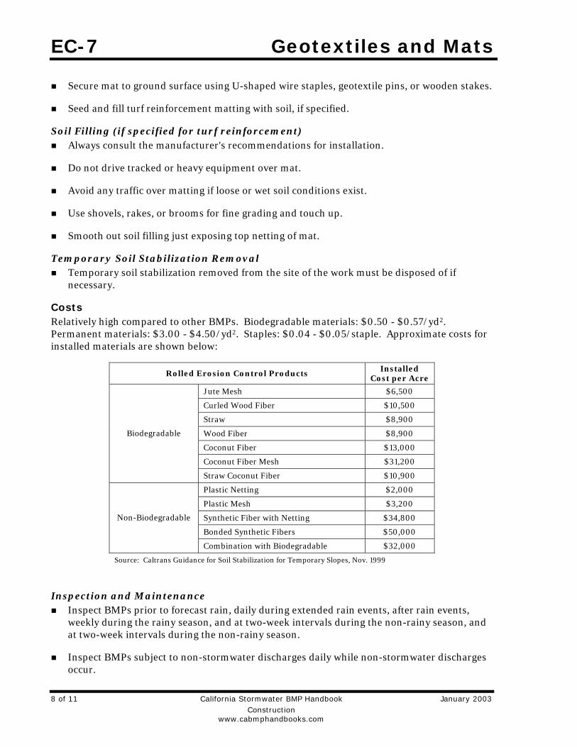
EC-7 Geotextiles and Mats
8 of 11 California Stormwater BMP Handbook January 2003 Construction www.cabmphandbooks.com
Secure mat to ground surface using U-shaped wire staples, geotextile pins, or wooden stakes.
Seed and fill turf reinforcement matting with soil, if specified.
Soil Filling (if specified for turf reinforcement) Always consult the manufacturer's recommendations for installation.
Do not drive tracked or heavy equipment over mat.
Avoid any traffic over matting if loose or wet soil conditions exist.
Use shovels, rakes, or brooms for fine grading and touch up.
Smooth out soil filling just exposing top netting of mat.
Temporary Soil Stabilization Removal Temporary soil stabilization removed from the site of the work must be disposed of if
necessary.
Costs Relatively high compared to other BMPs. Biodegradable materials: $0.50 - $0.57/yd2. Permanent materials: $3.00 - $4.50/yd2. Staples: $0.04 - $0.05/staple. Approximate costs for installed materials are shown below:
Rolled Erosion Control Products Installed Cost per Acre
Jute Mesh $6,500
Curled Wood Fiber $10,500
Straw $8,900
Wood Fiber $8,900
Coconut Fiber $13,000
Coconut Fiber Mesh $31,200
Biodegradable
Straw Coconut Fiber $10,900
Plastic Netting $2,000
Plastic Mesh $3,200
Synthetic Fiber with Netting $34,800
Bonded Synthetic Fibers $50,000
Non-Biodegradable
Combination with Biodegradable $32,000
Source: Caltrans Guidance for Soil Stabilization for Temporary Slopes, Nov. 1999
Inspection and Maintenance Inspect BMPs prior to forecast rain, daily during extended rain events, after rain events,
weekly during the rainy season, and at two-week intervals during the non-rainy season, and at two-week intervals during the non-rainy season.
Inspect BMPs subject to non-stormwater discharges daily while non-stormwater discharges occur.
Geotextiles and Mats EC-7
January 2003 California Stormwater BMP Handbook 9 of 11 Construction www.cabmphandbooks.com
Areas where erosion is evident shall be repaired and BMPs reapplied as soon as possible. Care should be exercised to minimize the damage to protected areas while making repairs, as any area damaged will require reapplication of BMPs.
If washout or breakage occurs, re-install the material after repairing the damage to the slope or channel.
Make sure matting is uniformly in contact with the soil.
Check that all the lap joints are secure.
Check that staples are flush with the ground.
Check that disturbed areas are seeded.
References Guides for Erosion and Sediment Controls in California, USDA Soils Conservation Service, January 1991.
National Management Measures to Control Nonpoint Source Pollution from Urban Areas, United States Environmental Protection Agency, 2002.
Stormwater Quality Handbooks Construction Site Best Management Practices (BMPs) Manual, State of California Department of Transportation (Caltrans), November 2000.
Guidance Document: Soil Stabilization for Temporary Slopes, State of California Department of Transportation (Caltrans), November 1999
Stormwater Management of the Puget Sound Basin, Technical Manual, Publication #91-75, Washington State Department of Ecology, February 1992.
Water Quality Management Plan for The Lake Tahoe Region, Volume II, Handbook of Management Practices, Tahoe Regional Planning Agency, November 1988.
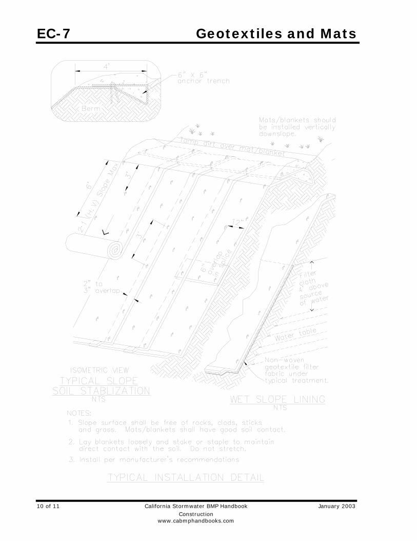
EC-7 Geotextiles and Mats
10 of 11 California Stormwater BMP Handbook January 2003 Construction www.cabmphandbooks.com
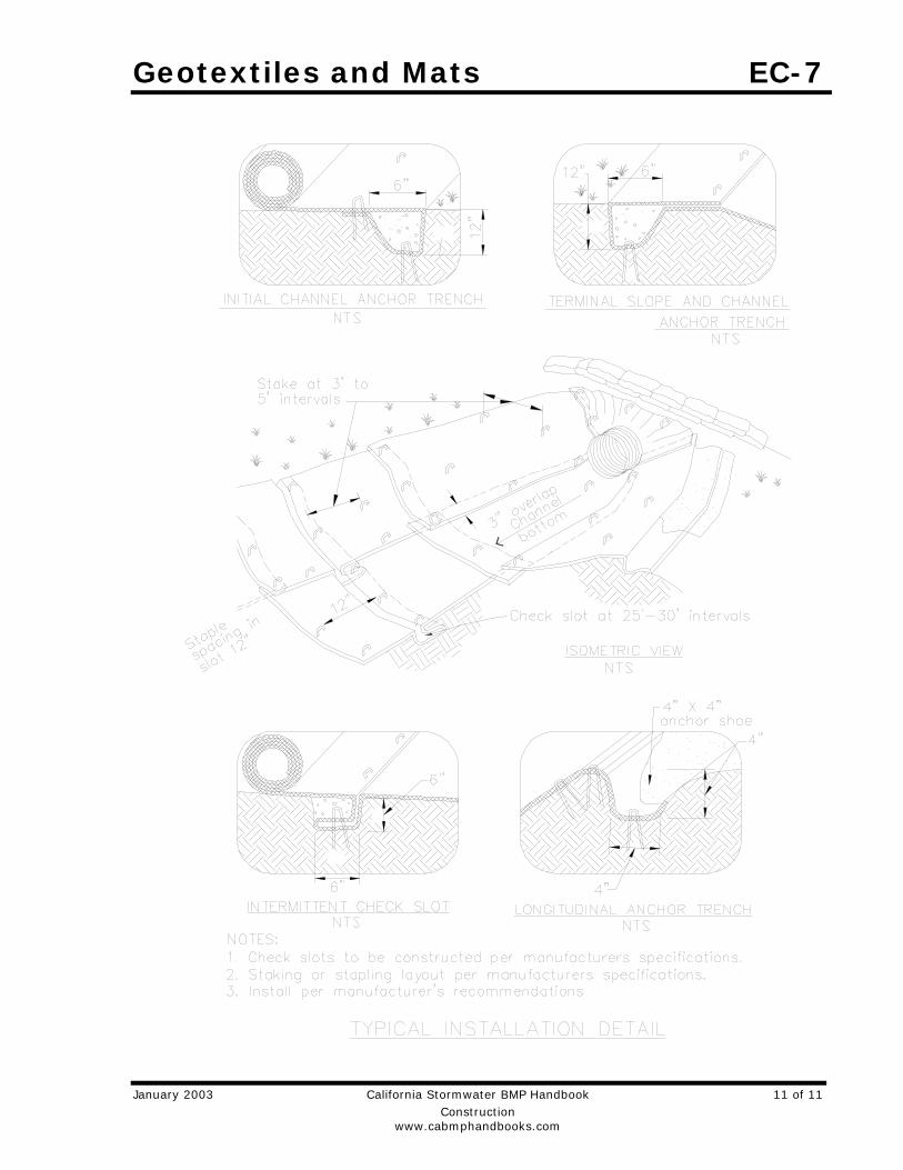
Geotextiles and Mats EC-7
January 2003 California Stormwater BMP Handbook 11 of 11 Construction www.cabmphandbooks.com

Silt Fence SE-1 Objectives
EC Erosion Control SE Sediment Control TR Tracking Control WE Wind Erosion Control
NS Non-Stormwater Management Control
WM Waste Management and Materials Pollution Control
Legend:
Primary Objective
Secondary Objective
Targeted Constituents
Sediment Nutrients Trash Metals Bacteria Oil and Grease Organics
Potential Alternatives
Description and Purpose A silt fence is made of a filter fabric that has been entrenched, attached to supporting poles, and sometimes backed by a plastic or wire mesh for support. The silt fence detains sediment-laden water, promoting sedimentation behind the fence.
Suitable Applications Silt fences are suitable for perimeter control, placed below areas where sheet flows discharge from the site. They should also be used as interior controls below disturbed areas where runoff may occur in the form of sheet and rill erosion. Silt fences are generally ineffective in locations where the flow is concentrated and are only applicable for sheet or overland flows. Silt fences are most effective when used in combination with erosion controls. Suitable applications include:
SE-5 Fiber Rolls
SE-6 Gravel Bag Berm
SE-8 Sandbag Barrier
Construction www.cabmphandbooks.com
SE-9 Straw Bale Barrier
Along the perimeter of a project.
Below the toe or down slope of exposed and erodible slopes.
Along streams and channels.
Around temporary spoil areas and stockpiles.
Below other small cleared areas.
Limitations Do not use in streams, channels, drain inlets, or anywhere flow
is concentrated.
January 2003 California Stormwater BMP Handbook 1 of 8
SE-1 Silt Fence
Do not use in locations where ponded water may cause flooding.
Do not place fence on a slope, or across any contour line. If not installed at the same elevation throughout, silt fences will create erosion.
Filter fences will create a temporary sedimentation pond on the upstream side of the fence and may cause temporary flooding. Fences not constructed on a level contour will be overtopped by concentrated flow resulting in failure of the filter fence.
Improperly installed fences are subject to failure from undercutting, overlapping, or collapsing.
- Not effective unless trenched and keyed in.
- Not intended for use as mid-slope protection on slopes greater than 4:1 (H:V).
- Do not allow water depth to exceed 1.5 ft at any point.
Implementation General A silt fence is a temporary sediment barrier consisting of filter fabric stretched across and attached to supporting posts, entrenched, and, depending upon the strength of fabric used, supported with plastic or wire mesh fence. Silt fences trap sediment by intercepting and detaining small amounts of sediment-laden runoff from disturbed areas in order to promote sedimentation behind the fence.
Silt fences are preferable to straw bale barriers in many cases. Laboratory work at the Virginia Highway and Transportation Research Council has shown that silt fences can trap a much higher percentage of suspended sediments than can straw bales. While the failure rate of silt fences is lower than that of straw bale barriers, there are many instances where silt fences have been improperly installed. The following layout and installation guidance can improve performance and should be followed:
Use principally in areas where sheet flow occurs.
Don't use in streams, channels, or anywhere flow is concentrated. Don’t use silt fences to divert flow.
Don't use below slopes subject to creep, slumping, or landslides.
Select filter fabric that retains 85% of soil by weight, based on sieve analysis, but that is not finer than an equivalent opening size of 70.
Install along a level contour, so water does not pond more than 1.5 ft at any point along the silt fence.
The maximum length of slope draining to any point along the silt fence should be 200 ft or less.
The maximum slope perpendicular to the fence line should be 1:1.
2 of 8 California Stormwater BMP Handbook January 2003 Construction www.cabmphandbooks.com
Silt Fence SE-1
Provide sufficient room for runoff to pond behind the fence and to allow sediment removal equipment to pass between the silt fence and toes of slopes or other obstructions. About 1200 ft2 of ponding area should be provided for every acre draining to the fence.
Turn the ends of the filter fence uphill to prevent stormwater from flowing around the fence.
Leave an undisturbed or stabilized area immediately down slope from the fence where feasible.
Silt fences should remain in place until the disturbed area is permanently stabilized.
Design and Layout Selection of a filter fabric is based on soil conditions at the construction site (which affect the equivalent opening size (EOS) fabric specification) and characteristics of the support fence (which affect the choice of tensile strength). The designer should specify a filter fabric that retains the soil found on the construction site yet that it has openings large enough to permit drainage and prevent clogging. The following criteria is recommended for selection of the equivalent opening size:
1. If 50 percent or less of the soil, by weight, will pass the U.S. Standard Sieve No. 200, select the EOS to retain 85 % of the soil. The EOS should not be finer than EOS 70.
2. For all other soil types, the EOS should be no larger than the openings in the U.S. Standard Sieve No. 70 except where direct discharge to a stream, lake, or wetland will occur, then the EOS should be no larger than Standard Sieve No. 100.
To reduce the chance of clogging, it is preferable to specify a fabric with openings as large as allowed by the criteria. No fabric should be specified with an EOS smaller than U.S. Standard Sieve No. 100. If 85% or more of a soil, by weight, passes through the openings in a No. 200 sieve, filter fabric should not be used. Most of the particles in such a soil would not be retained if the EOS was too large and they would clog the fabric quickly if the EOS were small enough to capture the soil.
The fence should be supported by a plastic or wire mesh if the fabric selected does not have sufficient strength and bursting strength characteristics for the planned application (as recommended by the fabric manufacturer). Filter fabric material should contain ultraviolet inhibitors and stabilizers to provide a minimum of six months of expected usable construction life at a temperature range of 0 °F to 120 °F.
Layout in accordance with attached figures.
For slopes steeper than 2:1 (H:V) and that contain a high number of rocks or large dirt clods that tend to dislodge, it may be necessary to install additional protection immediately adjacent to the bottom of the slope, prior to installing silt fence. Additional protection may be a chain link fence or a cable fence.
For slopes adjacent to sensitive receiving waters or Environmentally Sensitive Areas (ESAs), silt fence should be used in conjunction with erosion control BMPs.
January 2003 California Stormwater BMP Handbook 3 of 8 Construction www.cabmphandbooks.com
SE-1 Silt Fence
Materials Silt fence fabric should be woven polypropylene with a minimum width of 36 in. and a
minimum tensile strength of 100 lb force. The fabric should conform to the requirements in ASTM designation D4632 and should have an integral reinforcement layer. The reinforcement layer should be a polypropylene, or equivalent, net provided by the manufacturer. The permittivity of the fabric should be between 0.1 sec-1 and 0.15 sec-1 in conformance with the requirements in ASTM designation D4491.
Wood stakes should be commercial quality lumber of the size and shape shown on the plans. Each stake should be free from decay, splits or cracks longer than the thickness of the stake or other defects that would weaken the stakes and cause the stakes to be structurally unsuitable.
Staples used to fasten the fence fabric to the stakes should be not less than 1.75 in. long and should be fabricated from 15 gauge or heavier wire. The wire used to fasten the tops of the stakes together when joining two sections of fence should be 9 gauge or heavier wire. Galvanizing of the fastening wire will not be required.
There are new products that may use prefabricated plastic holders for the silt fence and use bar reinforcement instead of wood stakes. If bar reinforcement is used in lieu of wood stakes, use number four or greater bar. Provide end protection for any exposed bar reinforcement.
Installation Guidelines Silt fences are to be constructed on a level contour. Sufficient area should exist behind the fence for ponding to occur without flooding or overtopping the fence.
A trench should be excavated approximately 6 in. wide and 6 in. deep along the line the proposed silt fence.
Bottom of the silt fence should be keyed-in a minimum of 12 in.
Posts should be spaced a maximum of 6 ft apart and driven securely into the ground a minimum of 18 in. or 12 in. below the bottom of the trench.
When standard strength filter fabric is used, a plastic or wire mesh support fence should be fastened securely to the upslope side of posts using heavy–duty wire staples at least 1 in. long. The mesh should extend into the trench. When extra-strength filter fabric and closer post spacing are used, the mesh support fence may be eliminated. Filter fabric should be purchased in a long roll, and then cut to the length of the barrier. When joints are necessary, filter cloth should be spliced together only at a support post, with a minimum 6 in. overlap and both ends securely fastened to the post.
The trench should be backfilled with compacted native material.
Construct silt fences with a setback of at least 3 ft from the toe of a slope. Where a silt fence is determined to be not practicable due to specific site conditions, the silt fence may be constructed at the toe of the slope, but should be constructed as far from the toe of the slope as practicable. Silt fences close to the toe of the slope will be less effective and difficult to maintain.
4 of 8 California Stormwater BMP Handbook January 2003 Construction www.cabmphandbooks.com
Silt Fence SE-1
Construct the length of each reach so that the change in base elevation along the reach does not exceed 1/3 the height of the barrier; in no case should the reach exceed 500 ft.
Costs Average annual cost for installation and maintenance (assumes 6 month useful life): $7 per
lineal foot ($850 per drainage acre). Range of cost is $3.50 - $9.10 per lineal foot.
Inspection and Maintenance Inspect BMPs prior to forecast rain, daily during extended rain events, after rain events,
weekly during the rainy season, and at two-week intervals during the non-rainy season.
Repair undercut silt fences.
Repair or replace split, torn, slumping, or weathered fabric. The lifespan of silt fence fabric is generally 5 to 8 months.
Silt fences that are damaged and become unsuitable for the intended purpose should be removed from the site of work, disposed of, and replaced with new silt fence barriers.
Sediment that accumulates in the BMP must be periodically removed in order to maintain BMP effectiveness. Sediment should be removed when the sediment accumulation reaches one-third of the barrier height. Sediment removed during maintenance may be incorporated into earthwork on the site or disposed at an appropriate location.
Silt fences should be left in place until the upstream area is permanently stabilized. Until then, the silt fence must be inspected and maintained.
Holes, depressions, or other ground disturbance caused by the removal of the silt fences should be backfilled and repaired.
References Manual of Standards of Erosion and Sediment Control Measures, Association of Bay Area Governments, May 1995.
National Management Measures to Control Nonpoint Source Pollution from Urban Areas, United States Environmental Protection Agency, 2002.
Proposed Guidance Specifying Management Measures for Sources of Nonpoint Pollution in Coastal Waters, Work Group-Working Paper, USEPA, April 1992.
Sedimentation and Erosion Control Practices, and Inventory of Current Practices (Draft), UESPA, 1990.
Southeastern Wisconsin Regional Planning Commission (SWRPC). Costs of Urban Nonpoint Source Water Pollution Control Measures. Technical Report No. 31. Southeastern Wisconsin Regional Planning Commission, Waukesha, WI. 1991
Stormwater Quality Handbooks - Construction Site Best Management Practices (BMPs) Manual, State of California Department of Transportation (Caltrans), November 2000.
January 2003 California Stormwater BMP Handbook 5 of 8 Construction www.cabmphandbooks.com
SE-1 Silt Fence
Stormwater Management Manual for The Puget Sound Basin, Washington State Department of Ecology, Public Review Draft, 1991.
U.S. Environmental Protection Agency (USEPA). Stormwater Management for Industrial Activities: Developing Pollution Prevention Plans and Best Management Practices. U.S. Environmental Protection Agency, Office of Water, Washington, DC, 1992.
Water Quality Management Plan for the Lake Tahoe Region, Volume II, Handbook of Management Practices, Tahoe Regional Planning Agency, November 1988.
6 of 8 California Stormwater BMP Handbook January 2003 Construction www.cabmphandbooks.com

Silt Fence SE-1 Silt Fence SE-1
January 2003 California Stormwater BMP Handbook 7 of 8 Construction www.cabmphandbooks.com
January 2003 California Stormwater BMP Handbook 7 of 8 Construction www.cabmphandbooks.com
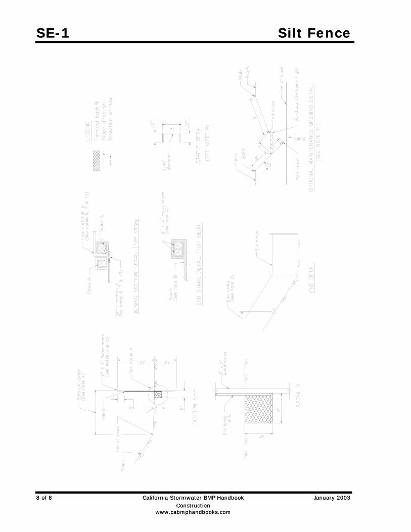
SE-1 Silt Fence SE-1 Silt Fence
8 of 8 California Stormwater BMP Handbook January 2003 Construction www.cabmphandbooks.com
8 of 8 California Stormwater BMP Handbook January 2003 Construction www.cabmphandbooks.com
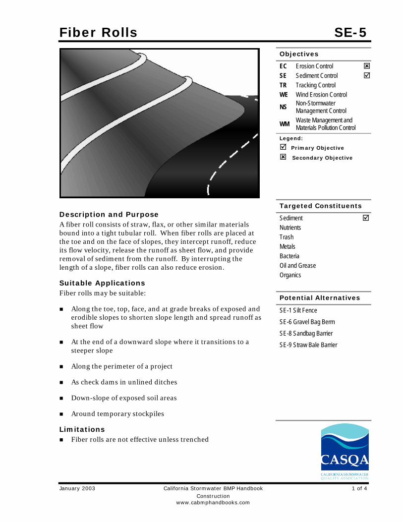
Fiber Rolls SE-5
January 2003 California Stormwater BMP Handbook 1 of 4 Construction www.cabmphandbooks.com
Description and Purpose A fiber roll consists of straw, flax, or other similar materials bound into a tight tubular roll. When fiber rolls are placed at the toe and on the face of slopes, they intercept runoff, reduce its flow velocity, release the runoff as sheet flow, and provide removal of sediment from the runoff. By interrupting the length of a slope, fiber rolls can also reduce erosion.
Suitable Applications Fiber rolls may be suitable:
Along the toe, top, face, and at grade breaks of exposed and erodible slopes to shorten slope length and spread runoff as sheet flow
At the end of a downward slope where it transitions to a steeper slope
Along the perimeter of a project
As check dams in unlined ditches
Down-slope of exposed soil areas
Around temporary stockpiles
Limitations Fiber rolls are not effective unless trenched
Objectives
EC Erosion Control SE Sediment Control TR Tracking Control WE Wind Erosion Control
NS Non-Stormwater Management Control
WM Waste Management and Materials Pollution Control
Legend:
Primary Objective
Secondary Objective
Targeted Constituents
Sediment Nutrients Trash Metals Bacteria Oil and Grease Organics
Potential Alternatives
SE-1 Silt Fence
SE-6 Gravel Bag Berm
SE-8 Sandbag Barrier
SE-9 Straw Bale Barrier
SE-5 Fiber Rolls
2 of 4 California Stormwater BMP Handbook January 2003 Construction www.cabmphandbooks.com
Fiber rolls at the toe of slopes greater than 5:1 (H:V) should be a minimum of 20 in. diameter or installations achieving the same protection (i.e. stacked smaller diameter fiber rolls, etc.).
Difficult to move once saturated.
If not properly staked and trenched in, fiber rolls could be transported by high flows.
Fiber rolls have a very limited sediment capture zone.
Fiber rolls should not be used on slopes subject to creep, slumping, or landslide.
Implementation Fiber Roll Materials
Fiber rolls should be either prefabricated rolls or rolled tubes of erosion control blanket.
Assembly of Field Rolled Fiber Roll Roll length of erosion control blanket into a tube of minimum 8 in. diameter.
Bind roll at each end and every 4 ft along length of roll with jute-type twine.
Installation Locate fiber rolls on level contours spaced as follows:
- Slope inclination of 4:1 (H:V) or flatter: Fiber rolls should be placed at a maximum interval of 20 ft.
- Slope inclination between 4:1 and 2:1 (H:V): Fiber Rolls should be placed at a maximum interval of 15 ft. (a closer spacing is more effective).
- Slope inclination 2:1 (H:V) or greater: Fiber Rolls should be placed at a maximum interval of 10 ft. (a closer spacing is more effective).
Turn the ends of the fiber roll up slope to prevent runoff from going around the roll.
Stake fiber rolls into a 2 to 4 in. deep trench with a width equal to the diameter of the fiber roll.
- Drive stakes at the end of each fiber roll and spaced 4 ft maximum on center.
- Use wood stakes with a nominal classification of 0.75 by 0.75 in. and minimum length of 24 in.
If more than one fiber roll is placed in a row, the rolls should be overlapped, not abutted.
Removal Fiber rolls are typically left in place.
Fiber Rolls SE-5
January 2003 California Stormwater BMP Handbook 3 of 4 Construction www.cabmphandbooks.com
If fiber rolls are removed, collect and dispose of sediment accumulation, and fill and compact holes, trenches, depressions or any other ground disturbance to blend with adjacent ground.
Costs Material costs for fiber rolls range from $20 - $30 per 25 ft roll.
Inspection and Maintenance Inspect BMPs prior to forecast rain, daily during extended rain events, after rain events,
weekly during the rainy season, and at two-week intervals during the non-rainy season.
Repair or replace split, torn, unraveling, or slumping fiber rolls.
If the fiber roll is used as a sediment capture device, or as an erosion control device to maintain sheet flows, sediment that accumulates in the BMP must be periodically removed in order to maintain BMP effectiveness. Sediment should be removed when sediment accumulation reaches one-half the designated sediment storage depth, usually one-half the distance between the top of the fiber roll and the adjacent ground surface. Sediment removed during maintenance may be incorporated into earthwork on the site of disposed at an appropriate location.
If fiber rolls are used for erosion control, such as in a mini check dam, sediment removal should not be required as long as the system continues to control the grade. Sediment control BMPs will likely be required in conjunction with this type of application.
References Stormwater Quality Handbooks - Construction Site Best Management Practices (BMPs) Manual, State of California Department of Transportation (Caltrans), November 2000.
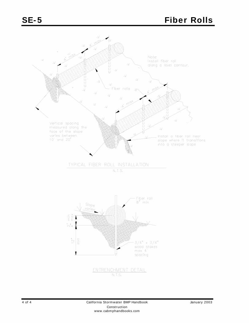
SE-5 Fiber Rolls
4 of 4 California Stormwater BMP Handbook January 2003 Construction www.cabmphandbooks.com
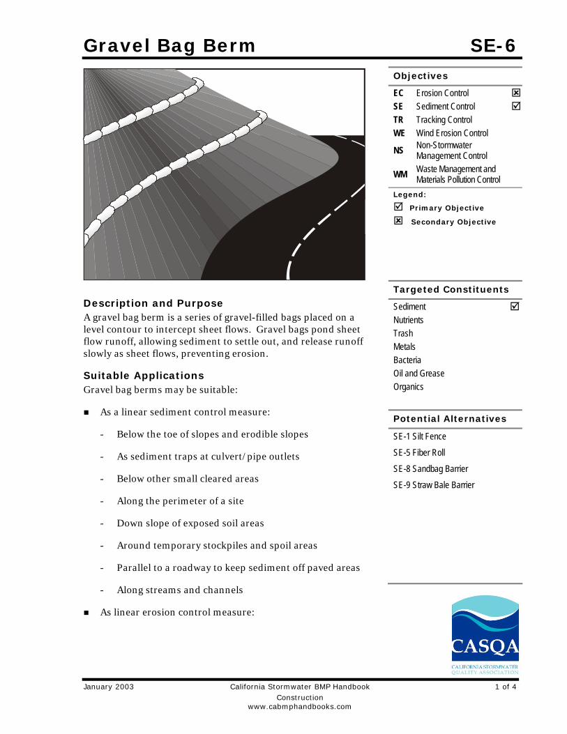
Gravel Bag Berm SE-6
January 2003 California Stormwater BMP Handbook 1 of 4 Construction www.cabmphandbooks.com
Description and Purpose A gravel bag berm is a series of gravel-filled bags placed on a level contour to intercept sheet flows. Gravel bags pond sheet flow runoff, allowing sediment to settle out, and release runoff slowly as sheet flows, preventing erosion.
Suitable Applications Gravel bag berms may be suitable:
As a linear sediment control measure:
- Below the toe of slopes and erodible slopes
- As sediment traps at culvert/pipe outlets
- Below other small cleared areas
- Along the perimeter of a site
- Down slope of exposed soil areas
- Around temporary stockpiles and spoil areas
- Parallel to a roadway to keep sediment off paved areas
- Along streams and channels
As linear erosion control measure:
Objectives
EC Erosion Control SE Sediment Control TR Tracking Control WE Wind Erosion Control
NS Non-Stormwater Management Control
WM Waste Management and Materials Pollution Control
Legend:
Primary Objective
Secondary Objective
Targeted Constituents
Sediment Nutrients Trash Metals Bacteria Oil and Grease Organics
Potential Alternatives
SE-1 Silt Fence
SE-5 Fiber Roll
SE-8 Sandbag Barrier
SE-9 Straw Bale Barrier

SE-6 Gravel Bag Berm
2 of 4 California Stormwater BMP Handbook January 2003 Construction www.cabmphandbooks.com
- Along the face and at grade breaks of exposed and erodible slopes to shorten slope length and spread runoff as sheet flow
- At the top of slopes to divert runoff away from disturbed slopes
- As check dams across mildly sloped construction roads
Limitations Gravel berms may be difficult to remove.
Removal problems limit their usefulness in landscaped areas.
Gravel bag berm may not be appropriate for drainage areas greater than 5 acres.
Runoff will pond upstream of the filter, possibly causing flooding if sufficient space does not exist.
Degraded gravel bags may rupture when removed, spilling contents.
Installation can be labor intensive.
Berms may have limited durability for long-term projects.
When used to detain concentrated flows, maintenance requirements increase.
Implementation General A gravel bag berm consists of a row of open graded gravel–filled bags placed on a level contour. When appropriately placed, a gravel bag berm intercepts and slows sheet flow runoff, causing temporary ponding. The temporary ponding provides quiescent conditions allowing sediment to settle. The open graded gravel in the bags is porous, which allows the ponded runoff to flow slowly through the bags, releasing the runoff as sheet flows. Gravel bag berms also interrupt the slope length and thereby reduce erosion by reducing the tendency of sheet flows to concentrate into rivulets, which erode rills, and ultimately gullies, into disturbed, sloped soils. Gravel bag berms are similar to sand bag barriers, but are more porous.
Design and Layout Locate gravel bag berms on level contours.
- Slopes between 20:1 and 2:1 (H:V): Gravel bags should be placed at a maximum interval of 50 ft (a closer spacing is more effective), with the first row near the slope toe.
- Slopes 2:1 (H:V) or steeper: Gravel bags should be placed at a maximum interval of 25 ft (a closer spacing is more effective), with the first row placed the slope toe.
Turn the ends of the gravel bag barriers up slope to prevent runoff from going around the berm.
Allow sufficient space up slope from the gravel bag berm to allow ponding, and to provide room for sediment storage.
Gravel Bag Berm SE-6
January 2003 California Stormwater BMP Handbook 3 of 4 Construction www.cabmphandbooks.com
For installation near the toe of the slope, consider moving the gravel bag barriers away from the slope toe to facilitate cleaning. To prevent flows behind the barrier, bags can be placed perpendicular to a berm to serve as cross barriers.
Drainage area should not exceed 5 acres.
In Non-Traffic Areas:
- Height = 18 in. maximum
- Top width = 24 in. minimum for three or more layer construction
- Top width = 12 in. minimum for one or two layer construction
- Side slopes = 2:1 or flatter
In Construction Traffic Areas:
- Height = 12 in. maximum
- Top width = 24 in. minimum for three or more layer construction.
- Top width = 12 in. minimum for one or two layer construction.
- Side slopes = 2:1 or flatter.
Butt ends of bags tightly
On multiple row, or multiple layer construction, overlapp butt joints of adjacent row and row beneath.
Use a pyramid approach when stacking bags.
Materials Bag Material: Bags should be woven polypropylene, polyethylene or polyamide fabric or
burlap, minimum unit weight of 4 ounces/yd2, Mullen burst strength exceeding 300 lb/in2 in conformance with the requirements in ASTM designation D3786, and ultraviolet stability exceeding 70% in conformance with the requirements in ASTM designation D4355.
Bag Size: Each gravel-filled bag should have a length of 18 in., width of 12 in., thickness of 3 in., and mass of approximately 33 lbs. Bag dimensions are nominal, and may vary based on locally available materials.
Fill Material: Fill material should be 0.5 to 1 in. Class 2 aggregate base, clean and free from clay, organic matter, and other deleterious material, or other suitable open graded, non-cohesive, porous gravel.
Costs Gravel filter: Expensive, since off-site materials, hand construction, and demolition/removal are usually required. Material costs for gravel bags are average of $2.50 per empty gravel bag. Gravel costs range from $20-$35 per yd3.
SE-6 Gravel Bag Berm
4 of 4 California Stormwater BMP Handbook January 2003 Construction www.cabmphandbooks.com
Inspection and Maintenance Inspect BMPs prior to forecast rain, daily during extended rain events, after rain events,
weekly during the rainy season, and at two-week intervals during the non-rainy season.
Gravel bags exposed to sunlight will need to be replaced every two to three months due to degrading of the bags.
Reshape or replace gravel bags as needed.
Repair washouts or other damage as needed.
Sediment that accumulates in the BMP must be periodically removed in order to maintain BMP effectiveness. Sediment should be removed when the sediment accumulation reaches one-third of the barrier height. Sediment removed during maintenance may be incorporated into earthwork on the site or disposed at an appropriate location.
Remove gravel bag berms when no longer needed. Remove sediment accumulation and clean, re-grade, and stabilize the area. Removed sediment should be incorporated in the project or disposed of.
References Handbook of Steel Drainage and Highway Construction, American Iron and Steel Institute, 1983.
Stormwater Quality Handbooks - Construction Site Best Management Practices (BMPs) Manual, State of California Department of Transportation (Caltrans), November 2000.
Stormwater Pollution Plan Handbook, First Edition, State of California, Department of Transportation Division of New Technology, Materials and Research, October 1992.

Street Sweeping and Vacuuming SE-7
January 2003 California Stormwater BMP Handbook 1 of 2 Construction www.cabmphandbooks.com
Description and Purpose Street sweeping and vacuuming includes use of self-propelled and walk-behind equipment to remove sediment from streets and roadways, and to clean paved surfaces in preparation for final paving. Sweeping and vacuuming prevents sediment from the project site from entering storm drains or receiving waters.
Suitable Applications Sweeping and vacuuming are suitable anywhere sediment is tracked from the project site onto public or private paved streets and roads, typically at points of egress. Sweeping and vacuuming are also applicable during preparation of paved surfaces for final paving.
Limitations Sweeping and vacuuming may not be effective when sediment is wet or when tracked soil is caked (caked soil may need to be scraped loose).
Implementation Controlling the number of points where vehicles can leave
the site will allow sweeping and vacuuming efforts to be focused, and perhaps save money.
Inspect potential sediment tracking locations daily.
Visible sediment tracking should be swept or vacuumed on a daily basis.
Objectives
EC Erosion Control SE Sediment Control TR Tracking Control WE Wind Erosion Control
NS Non-Stormwater Management Control
WM Waste Management and Materials Pollution Control
Legend:
Primary Objective
Secondary Objective
Targeted Constituents
Sediment Nutrients Trash Metals Bacteria Oil and Grease Organics
Potential Alternatives
None
SE-7 Street Sweeping and Vacuuming
2 of 2 California Stormwater BMP Handbook January 2003 Construction www.cabmphandbooks.com
Do not use kick brooms or sweeper attachments. These tend to spread the dirt rather than remove it.
If not mixed with debris or trash, consider incorporating the removed sediment back into the project
Costs Rental rates for self-propelled sweepers vary depending on hopper size and duration of rental. Expect rental rates from $58/hour (3 yd3 hopper) to $88/hour (9 yd3 hopper), plus operator costs. Hourly production rates vary with the amount of area to be swept and amount of sediment. Match the hopper size to the area and expect sediment load to minimize time spent dumping.
Inspection and Maintenance Inspect BMPs prior to forecast rain, daily during extended rain events, after rain events,
weekly during the rainy season, and at two-week intervals during the non-rainy season.
When actively in use, points of ingress and egress must be inspected daily.
When tracked or spilled sediment is observed outside the construction limits, it must be removed at least daily. More frequent removal, even continuous removal, may be required in some jurisdictions.
Be careful not to sweep up any unknown substance or any object that may be potentially hazardous.
Adjust brooms frequently; maximize efficiency of sweeping operations.
After sweeping is finished, properly dispose of sweeper wastes at an approved dumpsite.
References Stormwater Quality Handbooks - Construction Site Best Management Practices (BMPs) Manual, State of California Department of Transportation (Caltrans), November 2000.
Labor Surcharge and Equipment Rental Rates, State of California Department of Transportation (Caltrans), April 1, 2002 – March 31, 2003.
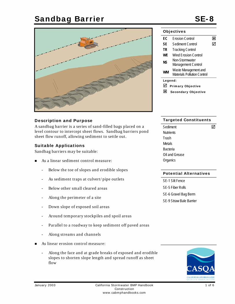
Sandbag Barrier SE-8
January 2003 California Stormwater BMP Handbook 1 of 6 Construction www.cabmphandbooks.com
Description and Purpose A sandbag barrier is a series of sand-filled bags placed on a level contour to intercept sheet flows. Sandbag barriers pond sheet flow runoff, allowing sediment to settle out.
Suitable Applications Sandbag barriers may be suitable:
As a linear sediment control measure:
- Below the toe of slopes and erodible slopes
- As sediment traps at culvert/pipe outlets
- Below other small cleared areas
- Along the perimeter of a site
- Down slope of exposed soil areas
- Around temporary stockpiles and spoil areas
- Parallel to a roadway to keep sediment off paved areas
- Along streams and channels
As linear erosion control measure:
- Along the face and at grade breaks of exposed and erodible slopes to shorten slope length and spread runoff as sheet flow
Objectives
EC Erosion Control SE Sediment Control TR Tracking Control WE Wind Erosion Control
NS Non-Stormwater Management Control
WM Waste Management and Materials Pollution Control
Legend:
Primary Objective
Secondary Objective
Targeted Constituents
Sediment Nutrients Trash Metals Bacteria Oil and Grease Organics
Potential Alternatives
SE-1 Silt Fence
SE-5 Fiber Rolls
SE-6 Gravel Bag Berm
SE-9 Straw Bale Barrier

SE-8 Sandbag Barrier
2 of 6 California Stormwater BMP Handbook January 2003 Construction www.cabmphandbooks.com
- At the top of slopes to divert runoff away from disturbed slopes
- As check dams across mildly sloped construction roads
Limitations It is necessary to limit the drainage area upstream of the barrier to 5 acres.
Degraded sandbags may rupture when removed, spilling sand.
Installation can be labor intensive.
Barriers may have limited durability for long-term projects.
When used to detain concentrated flows, maintenance requirements increase.
Burlap should not be used for sandbags.
Implementation General A sandbag barrier consists of a row of sand-filled bags placed on a level contour. When appropriately placed, a sandbag barrier intercepts and slows sheet flow runoff, causing temporary ponding. The temporary ponding provides quiescent conditions allowing sediment to settle. While the sand-filled bags are porous, the fine sand tends to quickly plug with sediment, limiting the rate of flow through the barrier. If a porous barrier is desired, consider SE-1, Silt Fence, SE-5, Fiber Rolls, SE-6, Gravel Bag Berms, or SE-9, Straw Bale Barriers. Sandbag barriers also interrupt the slope length and thereby reduce erosion by reducing the tendency of sheet flows to concentrate into rivulets which erode rills, and ultimately gullies, into disturbed, sloped soils. Sandbag barriers are similar to ground bag berms, but less porous.
Design and Layout Locate sandbag barriers on a level contour.
- Slopes between 20:1 and 2:1 (H:V): Sandbags should be placed at a maximum interval of 50 ft (a closer spacing is more effective), with the first row near the slope toe.
- Slopes 2:1 (H:V) or steeper: Sandbags should be placed at a maximum interval of 25 ft (a closer spacing is more effective), with the first row placed near the slope toe.
Turn the ends of the sandbag barrier up slope to prevent runoff from going around the barrier.
Allow sufficient space up slope from the barrier to allow ponding, and to provide room for sediment storage.
For installation near the toe of the slope, consider moving the barrier away from the slope toe to facilitate cleaning. To prevent flow behind the barrier, sandbags can be placed perpendicular to the barrier to serve as cross barriers.
Drainage area should not exceed 5 acres.

Sandbag Barrier SE-8
January 2003 California Stormwater BMP Handbook 3 of 6 Construction www.cabmphandbooks.com
Stack sandbags at least three bags high.
Butt ends of bags tightly.
Overlapp butt joints of row beneath with each successive row.
Use a pyramid approach when stacking bags.
In non-traffic areas
- Height = 18 in. maximum
- Top width = 24 in. minimum for three or more layer construction
- Side slope = 2:1 or flatter
In construction traffic areas
- Height = 12 in. maximum
- Top width = 24 in. minimum for three or more layer construction.
- Side slopes = 2:1 or flatter.
Materials Sandbag Material: Sandbag should be woven polypropylene, polyethylene or polyamide
fabric, minimum unit weight of 4 ounces/yd2, Mullen burst strength exceeding 300 lb/in2 in conformance with the requirements in ASTM designation D3786, and ultraviolet stability exceeding 70% in conformance with the requirements in ASTM designation D4355. Use of burlap may not acceptable in some jurisdictions.
Sandbag Size: Each sand-filled bag should have a length of 18 in., width of 12 in., thickness of 3 in., and mass of approximately 33 lbs. Bag dimensions are nominal, and may vary based on locally available materials.
Fill Material: All sandbag fill material should be non-cohesive, Class 1 or Class 2 permeable material free from clay and deleterious material.
Costs Sandbag barriers are more costly, but typically have a longer useful life than other barriers. Empty sandbags cost $0.25 - $0.75. Average cost of fill material is $8 per yd3. Pre-filled sandbags are more expensive at $1.50 - $2.00 per bag.
Inspection and Maintenance Inspect BMPs prior to forecast rain, daily during extended rain events, after rain events,
weekly during the rainy season, and at two-week intervals during the non-rainy season.
Sandbags exposed to sunlight will need to be replaced every two to three months due to degradation of the bags.
Reshape or replace sandbags as needed.

SE-8 Sandbag Barrier
4 of 6 California Stormwater BMP Handbook January 2003 Construction www.cabmphandbooks.com
Repair washouts or other damage as needed.
Sediment that accumulates in the BMP must be periodically removed in order to maintain BMP effectiveness. Sediment should be removed when the sediment accumulation reaches one-third of the barrier height. Sediment removed during maintenance may be incorporated into earthwork on the site or disposed at an appropriate location.
Remove sandbags when no longer needed. Remove sediment accumulation, and clean, re-grade, and stabilize the area.
References Stormwater Quality Handbooks - Construction Site Best Management Practices (BMPs) Manual, State of California Department of Transportation (Caltrans), November 2000.
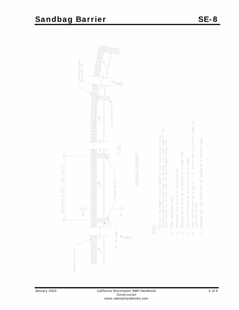
Sandbag Barrier SE-8
January 2003 California Stormwater BMP Handbook 5 of 6 Construction www.cabmphandbooks.com
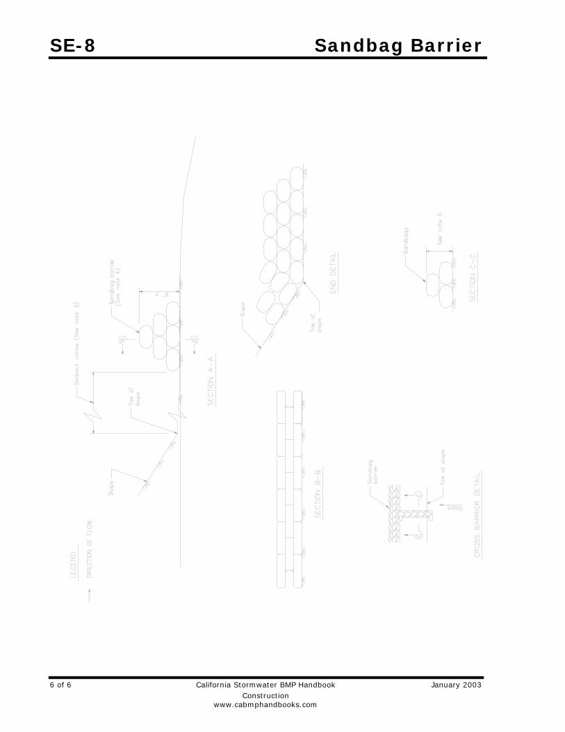
SE-8 Sandbag Barrier
6 of 6 California Stormwater BMP Handbook January 2003 Construction www.cabmphandbooks.com
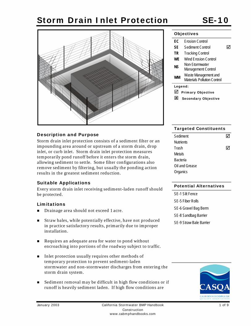
Storm Drain Inlet Protection SE-10
January 2003 California Stormwater BMP Handbook 1 of 9 Construction www.cabmphandbooks.com
Description and Purpose Storm drain inlet protection consists of a sediment filter or an impounding area around or upstream of a storm drain, drop inlet, or curb inlet. Storm drain inlet protection measures temporarily pond runoff before it enters the storm drain, allowing sediment to settle. Some filter configurations also remove sediment by filtering, but usually the ponding action results in the greatest sediment reduction.
Suitable Applications Every storm drain inlet receiving sediment-laden runoff should be protected.
Limitations Drainage area should not exceed 1 acre.
Straw bales, while potentially effective, have not produced in practice satisfactory results, primarily due to improper installation.
Requires an adequate area for water to pond without encroaching into portions of the roadway subject to traffic.
Inlet protection usually requires other methods of temporary protection to prevent sediment-laden stormwater and non-stormwater discharges from entering the storm drain system.
Sediment removal may be difficult in high flow conditions or if runoff is heavily sediment laden. If high flow conditions are
Objectives
EC Erosion Control SE Sediment Control TR Tracking Control WE Wind Erosion Control
NS Non-Stormwater Management Control
WM Waste Management and Materials Pollution Control
Legend:
Primary Objective
Secondary Objective
Targeted Constituents
Sediment Nutrients Trash Metals Bacteria Oil and Grease Organics
Potential Alternatives
SE-1 Silt Fence
SE-5 Fiber Rolls
SE-6 Gravel Bag Berm
SE-8 Sandbag Barrier
SE-9 Straw Bale Barrier

SE-10 Storm Drain Inlet Protection
2 of 9 California Stormwater BMP Handbook January 2003 Construction www.cabmphandbooks.com
expected, use other onsite sediment trapping techniques in conjunction with inlet protection.
Frequent maintenance is required.
For drainage areas larger than 1 acre, runoff should be routed to a sediment-trapping device designed for larger flows. See BMPs SE-2, Sediment Basin, and SE-3, Sediment Traps.
Excavated drop inlet sediment traps are appropriate where relatively heavy flows are expected, and overflow capability is needed.
Implementation General Large amounts of sediment may enter the storm drain system when storm drains are installed before the upslope drainage area is stabilized, or where construction is adjacent to an existing storm drain. In cases of extreme sediment loading, the storm drain itself may clog and lose a major portion of its capacity. To avoid these problems, it is necessary to prevent sediment from entering the system at the inlets.
Inlet control measures presented in this handbook should not be used for inlets draining more than one acre. Runoff from larger disturbed areas should be first routed through SE-2, Sediment Basin or SE-3, Sediment Trap. Different types of inlet protection are appropriate for different applications depending on site conditions and the type of inlet. Inlet protection methods not presented in this handbook should be approved by the local stormwater management agency.
Design and Layout Identify existing and planned storm drain inlets that have the potential to receive sediment-laden surface runoff. Determine if storm drain inlet protection is needed and which method to use.
Limit upstream drainage area to 1 acre maximum. For larger drainage areas, use SE-2, Sediment Basin, or SE-3, Sediment Trap, upstream of the inlet protection device.
The key to successful and safe use of storm drain inlet protection devices is to know where runoff will pond or be diverted.
- Determine the acceptable location and extent of ponding in the vicinity of the drain inlet. The acceptable location and extent of ponding will influence the type and design of the storm drain inlet protection device.
- Determine the extent of potential runoff diversion caused by the storm drain inlet protection device. Runoff ponded by inlet protection devices may flow around the device and towards the next downstream inlet. In some cases, this is acceptable; in other cases, serious erosion or downstream property damage can be caused by these diversions. The possibility of runoff diversions will influence whether or not storm drain inlet protection is suitable; and, if suitable, the type and design of the device.
The location and extent of ponding, and the extent of diversion, can usually be controlled through appropriate placement of the inlet protection device. In some cases, moving the
Storm Drain Inlet Protection SE-10
January 2003 California Stormwater BMP Handbook 3 of 9 Construction www.cabmphandbooks.com
inlet protection device a short distance upstream of the actual inlet can provide more efficient sediment control, limit ponding to desired areas, and prevent or control diversions.
Four types of inlet protection are presented below. However, it is recognized that other effective methods and proprietary devices exist and may be selected.
- Filter Fabric Fence: Appropriate for drainage basins with less than a 5% slope, sheet flows, and flows under 0.5 cfs.
- Excavated Drop Inlet Sediment Trap: An excavated area around the inlet to trap sediment (SE-3).
- Gravel bag barrier: Used to create a small sediment trap upstream of inlets on sloped, paved streets. Appropriate for sheet flow or when concentrated flow may exceed 0.5 cfs, and where overtopping is required to prevent flooding.
- Block and Gravel Filter: Appropriate for flows greater than 0.5 cfs.
Select the appropriate type of inlet protection and design as referred to or as described in this fact sheet.
Provide area around the inlet for water to pond without flooding structures and property.
Grates and spaces around all inlets should be sealed to prevent seepage of sediment-laden water.
Excavate sediment sumps (where needed) 1 to 2 ft with 2:1 side slopes around the inlet.
Installation DI Protection Type 1 - Filter Fabric Fence - The filter fabric fence (Type 1) protection
is shown in the attached figure. Similar to constructing a silt fence; see BMP SE-1, Silt Fence. Do not place filter fabric underneath the inlet grate since the collected sediment may fall into the drain inlet when the fabric is removed or replaced.
1. Excavate a trench approximately 6 in. wide and 6 in. deep along the line of the silt fence inlet protection device.
2. Place 2 in. by 2 in. wooden stakes around the perimeter of the inlet a maximum of 3 ft apart and drive them at least 18 in. into the ground or 12 in. below the bottom of the trench. The stakes must be at least 48 in.
3. Lay fabric along bottom of trench, up side of trench, and then up stakes. See SE-1, Silt Fence, for details. The maximum silt fence height around the inlet is 24 in.
4. Staple the filter fabric (for materials and specifications, see SE-1, Silt Fence) to wooden stakes. Use heavy-duty wire staples at least 1 in. in length.
5. Backfill the trench with gravel or compacted earth all the way around.
DI Protection Type 2 - Excavated Drop Inlet Sediment Trap - The excavated drop inlet sediment trap (Type 2) is shown in the attached figures. Install filter fabric fence in
SE-10 Storm Drain Inlet Protection
4 of 9 California Stormwater BMP Handbook January 2003 Construction www.cabmphandbooks.com
accordance with DI Protection Type 1. Size excavated trap to provide a minimum storage capacity calculated at the rate 67 yd3/acre of drainage area.
DI Protection Type 3 - Gravel bag - The gravel bag barrier (Type 3) is shown in the figures. Flow from a severe storm should not overtop the curb. In areas of high clay and silts, use filter fabric and gravel as additional filter media. Construct gravel bags in accordance with SE-6, Gravel Bag Berm. Gravel bags should be used due to their high permeability.
1. Use sand bag made of geotextile fabric (not burlap) and fill with 0.75 in. rock or 0.25 in. pea gravel.
2. Construct on gently sloping street.
3. Leave room upstream of barrier for water to pond and sediment to settle.
4. Place several layers of sand bags – overlapping the bags and packing them tightly together.
5. Leave gap of one bag on the top row to serve as a spillway. Flow from a severe storm (e.g., 10 year storm) should not overtop the curb.
DI Protection Type 4 – Block and Gravel Filter - The block and gravel filter (Type 4) is shown in the figures. Block and gravel filters are suitable for curb inlets commonly used in residential, commercial, and industrial construction.
1. Place hardware cloth or comparable wire mesh with 0.5 in. openings over the drop inlet so that the wire extends a minimum of 1 ft beyond each side of the inlet structure. If more than one strip is necessary, overlap the strips. Place filter fabric over the wire mesh.
2. Place concrete blocks lengthwise on their sides in a single row around the perimeter of the inlet, so that the open ends face outward, not upward. The ends of adjacent blocks should abut. The height of the barrier can be varied, depending on design needs, by stacking combinations of blocks that are 4 in., 8 in., and 12 in. wide. The row of blocks should be at least 12 in. but no greater than 24 in. high.
3. Place wire mesh over the outside vertical face (open end) of the concrete blocks to prevent stone from being washed through the blocks. Use hardware cloth or comparable wire mesh with 0.5 in. opening.
4. Pile washed stone against the wire mesh to the top of the blocks. Use 0.75 to 3 in.
Costs Average annual cost for installation and maintenance (one year useful life) is $200 per inlet.
Inspection and Maintenance Inspect BMPs prior to forecast rain, daily during extended rain events, after rain events,
weekly during the rainy season, and at two-week intervals during the non-rainy season.

Storm Drain Inlet Protection SE-10
January 2003 California Stormwater BMP Handbook 5 of 9 Construction www.cabmphandbooks.com
Filter Fabric Fences. If the fabric becomes clogged, torn, or degrades, it should be replaced. Make sure the stakes are securely driven in the ground and are in good shape (i.e., not bent, cracked, or splintered, and are reasonably perpendicular to the ground). Replace damaged stakes.
Gravel Filters. If the gravel becomes clogged with sediment, it must be carefully removed from the inlet and either cleaned or replaced. Since cleaning gravel at a construction site may be difficult, consider using the sediment-laden stone as fill material and put fresh stone around the inlet. Inspect bags for holes, gashes, and snags, and replace bags as needed. Check gravel bags for proper arrangement and displacement.
Sediment that accumulates in the BMP must be periodically removed in order to maintain BMP effectiveness. Sediment should be removed when the sediment accumulation reaches one-third of the barrier height. Sediment removed during maintenance may be incorporated into earthwork on the site ore disposed at an appropriate location.
Remove storm drain inlet protection once the drainage area is stabilized.
- Clean and regrade area around the inlet and clean the inside of the storm drain inlet as it must be free of sediment and debris at the time of final inspection.
References Stormwater Quality Handbooks - Construction Site Best Management Practices (BMPs) Manual, State of California Department of Transportation (Caltrans), November 2000.
Stormwater Management Manual for The Puget Sound Basin, Washington State Department of Ecology, Public Review Draft, 1991.
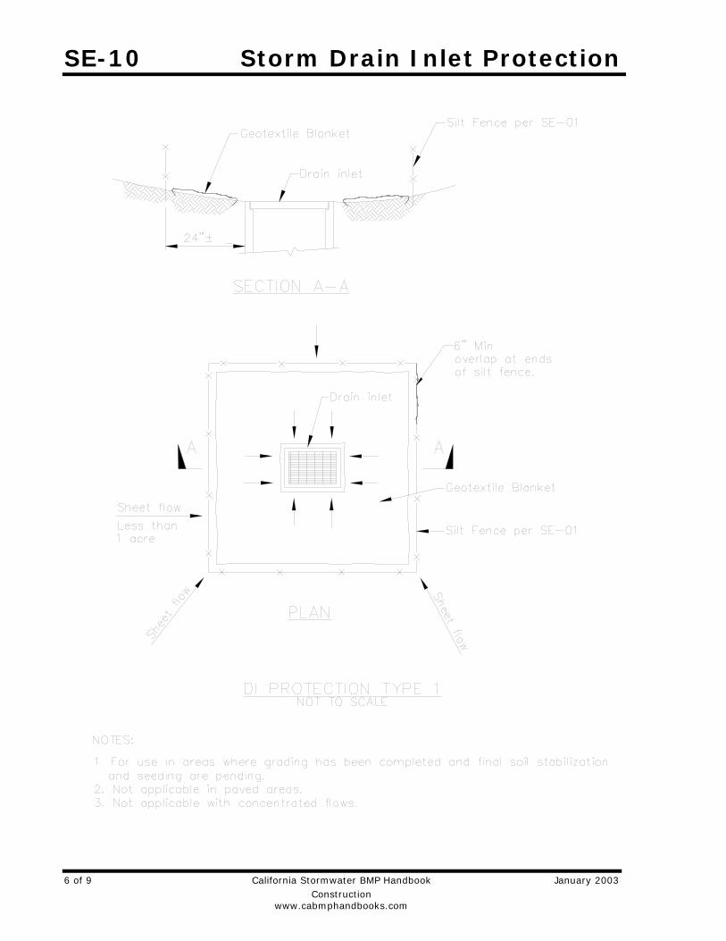
SE-10 Storm Drain Inlet Protection
6 of 9 California Stormwater BMP Handbook January 2003 Construction www.cabmphandbooks.com
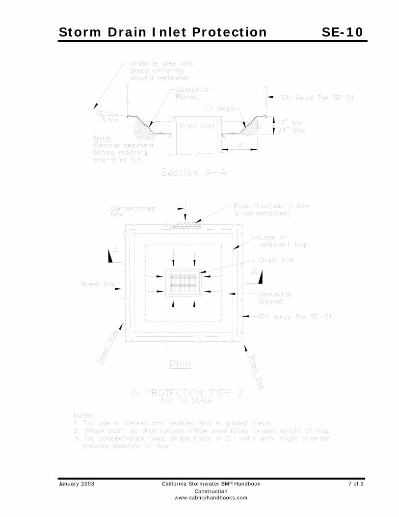
Storm Drain Inlet Protection SE-10
January 2003 California Stormwater BMP Handbook 7 of 9 Construction www.cabmphandbooks.com
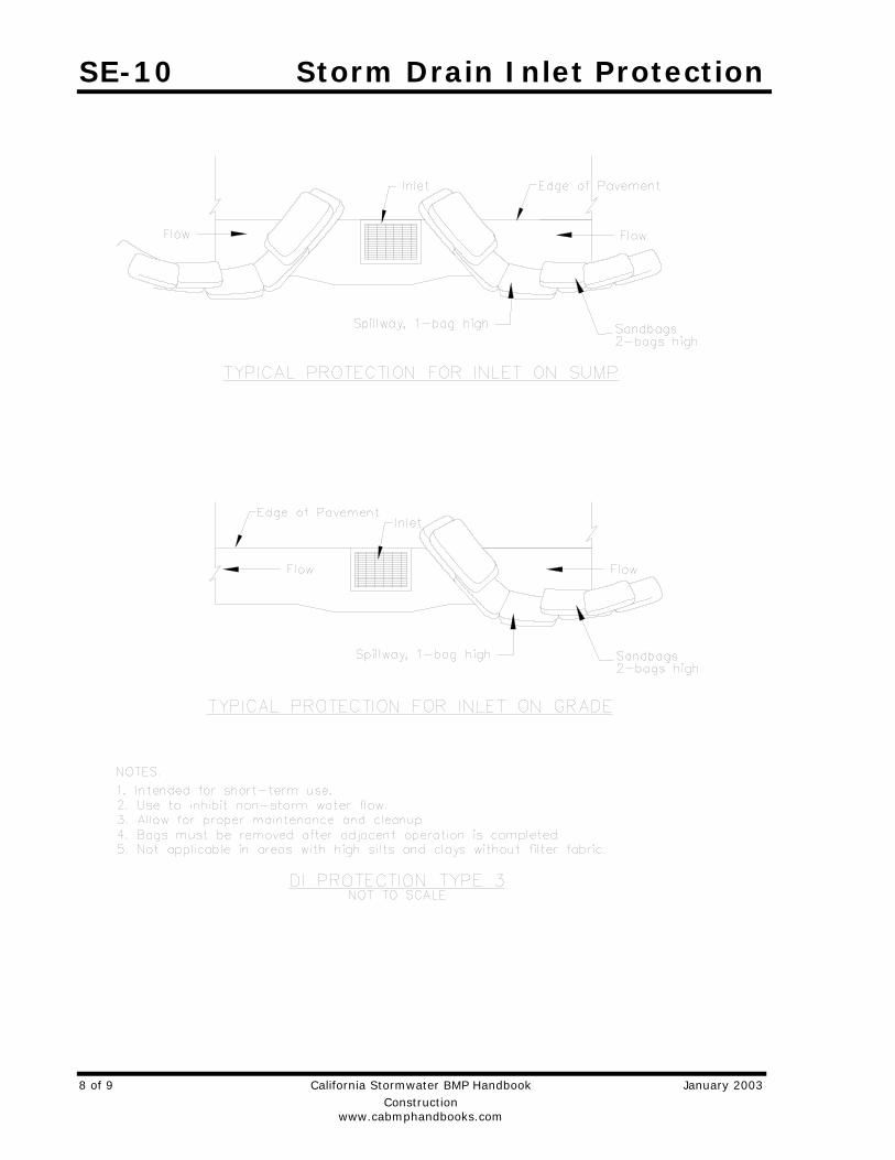
SE-10 Storm Drain Inlet Protection
8 of 9 California Stormwater BMP Handbook January 2003 Construction www.cabmphandbooks.com
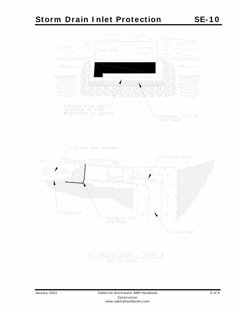
Storm Drain Inlet Protection SE-10
January 2003 California Stormwater BMP Handbook 9 of 9 Construction www.cabmphandbooks.com
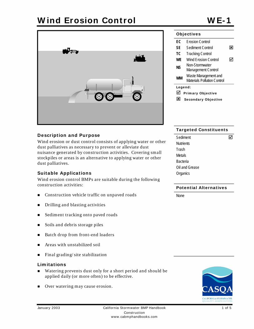
Wind Erosion Control WE-1
January 2003 California Stormwater BMP Handbook 1 of 5 Construction www.cabmphandbooks.com
Description and Purpose Wind erosion or dust control consists of applying water or other dust palliatives as necessary to prevent or alleviate dust nuisance generated by construction activities. Covering small stockpiles or areas is an alternative to applying water or other dust palliatives.
Suitable Applications Wind erosion control BMPs are suitable during the following construction activities:
Construction vehicle traffic on unpaved roads
Drilling and blasting activities
Sediment tracking onto paved roads
Soils and debris storage piles
Batch drop from front-end loaders
Areas with unstabilized soil
Final grading/site stabilization
Limitations Watering prevents dust only for a short period and should be
applied daily (or more often) to be effective.
Over watering may cause erosion.
Objectives
EC Erosion Control SE Sediment Control TC Tracking Control WE Wind Erosion Control
NS Non-Stormwater Management Control
WM Waste Management and Materials Pollution Control
Legend:
Primary Objective
Secondary Objective
Targeted Constituents
Sediment Nutrients Trash Metals Bacteria Oil and Grease Organics
Potential Alternatives
None
WE-1 Wind Erosion Control
2 of 5 California Stormwater BMP Handbook January 2003 Construction www.cabmphandbooks.com
Oil or oil-treated subgrade should not be used for dust control because the oil may migrate into drainageways and/or seep into the soil.
Effectiveness depends on soil, temperature, humidity, and wind velocity.
Chemically treated sub grades may make the soil water repellant, interfering with long-term infiltration and the vegetation/re-vegetation of the site. Some chemical dust suppressants may be subject to freezing and may contain solvents and should be handled properly.
Asphalt, as a mulch tack or chemical mulch, requires a 24-hour curing time to avoid adherence to equipment, worker shoes, etc. Application should be limited because asphalt surfacing may eventually migrate into the drainage system.
In compacted areas, watering and other liquid dust control measures may wash sediment or other constituents into the drainage system.
Implementation General California’s Mediterranean climate, with short wet seasons and long hot dry seasons, allows the soils to thoroughly dry out. During these dry seasons, construction activities are at their peak, and disturbed and exposed areas are increasingly subject to wind erosion, sediment tracking and dust generated by construction equipment.
Dust control, as a BMP, is a practice that is already in place for many construction activities. Los Angeles, the North Coast, and Sacramento, among others, have enacted dust control ordinances for construction activities that cause dust to be transported beyond the construction project property line.
Recently, the State Air Resources Control Board has, under the authority of the Clean Air Act, started to address air quality in relation to inhalable particulate matter less than 10 microns (PM-10). Approximately 90 percent of these small particles are considered to be dust. Existing dust control regulations by local agencies, municipal departments, public works department, and public health departments are in place in some regions within California.
Many local agencies require dust control in order to comply with local nuisance laws, opacity laws (visibility impairment) and the requirements of the Clean Air Act. The following are measures that local agencies may have already implemented as requirements for dust control from contractors:
Construction and Grading Permits: Require provisions for dust control plans.
Opacity Emission Limits: Enforce compliance with California air pollution control laws.
Increase Overall Enforcement Activities: Priority given to cases involving citizen complaints.
Maintain Field Application Records: Require records of dust control measures from contractor;
Stormwater Pollution Prevention Plan: (SWPPP): Integrate dust control measures into SWPPP.
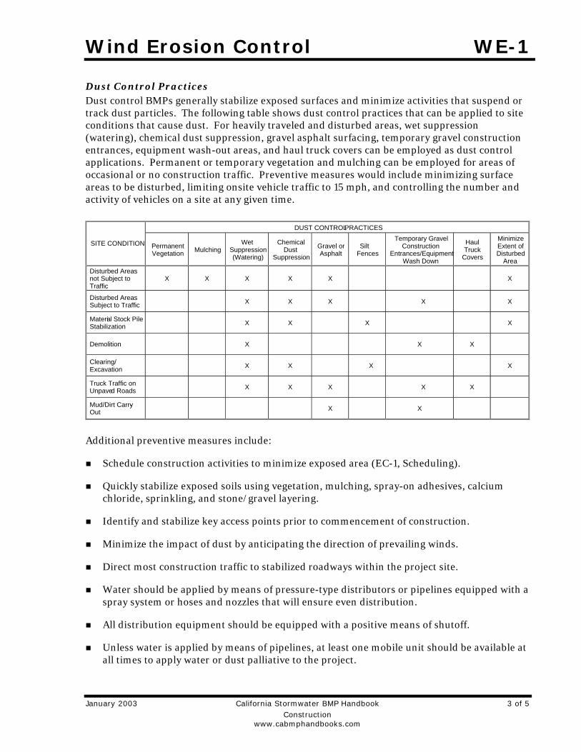
Wind Erosion Control WE-1
January 2003 California Stormwater BMP Handbook 3 of 5 Construction www.cabmphandbooks.com
Dust Control Practices Dust control BMPs generally stabilize exposed surfaces and minimize activities that suspend or track dust particles. The following table shows dust control practices that can be applied to site conditions that cause dust. For heavily traveled and disturbed areas, wet suppression (watering), chemical dust suppression, gravel asphalt surfacing, temporary gravel construction entrances, equipment wash-out areas, and haul truck covers can be employed as dust control applications. Permanent or temporary vegetation and mulching can be employed for areas of occasional or no construction traffic. Preventive measures would include minimizing surface areas to be disturbed, limiting onsite vehicle traffic to 15 mph, and controlling the number and activity of vehicles on a site at any given time.
Additional preventive measures include:
Schedule construction activities to minimize exposed area (EC-1, Scheduling).
Quickly stabilize exposed soils using vegetation, mulching, spray-on adhesives, calcium chloride, sprinkling, and stone/gravel layering.
Identify and stabilize key access points prior to commencement of construction.
Minimize the impact of dust by anticipating the direction of prevailing winds.
Direct most construction traffic to stabilized roadways within the project site.
Water should be applied by means of pressure-type distributors or pipelines equipped with a spray system or hoses and nozzles that will ensure even distribution.
All distribution equipment should be equipped with a positive means of shutoff.
Unless water is applied by means of pipelines, at least one mobile unit should be available at all times to apply water or dust palliative to the project.
DUST CONTROL PRACTICES
SITE CONDITION Permanent Vegetation
Mulching Wet
Suppression (Watering)
Chemical Dust
Suppression
Gravel or Asphalt
Silt Fences
Temporary Gravel Construction
Entrances/Equipment Wash Down
Haul Truck
Covers
Minimize Extent of Disturbed
AreaDisturbed Areas not Subject to Traffic
X X X X X X
Disturbed Areas Subject to Traffic X X X X X
Materia l Stock Pile Stabilization X X X X
Demolition X X X
Clearing/ Excavation X X X X
Truck Traffic on Unpave d Roads X X X X X
Mud/Dirt Carry -Out X X

WE-1 Wind Erosion Control
4 of 5 California Stormwater BMP Handbook January 2003 Construction www.cabmphandbooks.com
If reclaimed waste water is used, the sources and discharge must meet California Department of Health Services water reclamation criteria and the Regional Water Quality Control Board requirements. Non-potable water should not be conveyed in tanks or drain pipes that will be used to convey potable water and there should be no connection between potable and non-potable supplies. Non-potable tanks, pipes, and other conveyances should be marked, “NON-POTABLE WATER - DO NOT DRINK.”
Materials applied as temporary soil stabilizers and soil binders also generally provide wind erosion control benefits.
Pave or chemically stabilize access points where unpaved traffic surfaces adjoin paved roads.
Provide covers for haul trucks transporting materials that contribute to dust.
Provide for wet suppression or chemical stabilization of exposed soils.
Provide for rapid clean up of sediments deposited on paved roads. Furnish stabilized construction road entrances and vehicle wash down areas.
Stabilize inactive construction sites using vegetation or chemical stabilization methods.
Limit the amount of areas disturbed by clearing and earth moving operations by scheduling these activities in phases.
For chemical stabilization, there are many products available for chemically stabilizing gravel roadways and stockpiles. If chemical stabilization is used, the chemicals should not create any adverse effects on stormwater, plant life, or groundwater.
Costs Installation costs for water and chemical dust suppression are low, but annual costs may be quite high since these measures are effective for only a few hours to a few days.
Inspection and Maintenance Inspect and verify that activity-based BMPs are in place prior to the commencement of
associated activities. While activities associated with the BMP are under way, inspect weekly during the rainy season and at two-week intervals in the non-rainy season to verify continued BMP implementation.
Check areas protected to ensure coverage.
Most dust control measures require frequent, often daily, or multiple times per day attention.
References Best Management Practices and Erosion Control Manual for Construction Sites, Flood Control District of Maricopa County, Arizona, September 1992.
California Air Pollution Control Laws, California Air Resources Board, 1992.
Wind Erosion Control WE-1
January 2003 California Stormwater BMP Handbook 5 of 5 Construction www.cabmphandbooks.com
Caltrans, Standard Specifications, Sections 10, “Dust Control”; Section 17, “Watering”; and Section 18, “Dust Palliative”.
Prospects for Attaining the State Ambient Air Quality Standards for Suspended Particulate Matter (PM10), Visibility Reducing Particles, Sulfates, Lead, and Hydrogen Sulfide, California Air Resources Board, April 1991.
Stormwater Quality Handbooks Construction Site Best Management Practices (BMPs) Manual, State of California Department of Transportation (Caltrans), November 2000.

Stabilized Construction Entrance/Exit TC-1
January 2003 California Stormwater BMP Handbook 1 of 6 Construction www.cabmphandbooks.com
Description and Purpose A stabilized construction access is defined by a point of entrance/exit to a construction site that is stabilized to reduce the tracking of mud and dirt onto public roads by construction vehicles.
Suitable Applications Use at construction sites:
Where dirt or mud can be tracked onto public roads.
Adjacent to water bodies.
Where poor soils are encountered.
Where dust is a problem during dry weather conditions.
Limitations Entrances and exits require periodic top dressing with
additional stones.
This BMP should be used in conjunction with street sweeping on adjacent public right of way.
Entrances and exits should be constructed on level ground only.
Stabilized construction entrances are rather expensive to construct and when a wash rack is included, a sediment trap of some kind must also be provided to collect wash water runoff.
Objectives
EC Erosion Control SE Sediment Control TC Tracking Control WE Wind Erosion Control
NS Non-Stormwater Management Control
WM Waste Management and Materials Pollution Control
Legend:
Primary Objective
Secondary Objective
Targeted Constituents
Sediment Nutrients Trash Metals Bacteria Oil and Grease Organics
Potential Alternatives
None
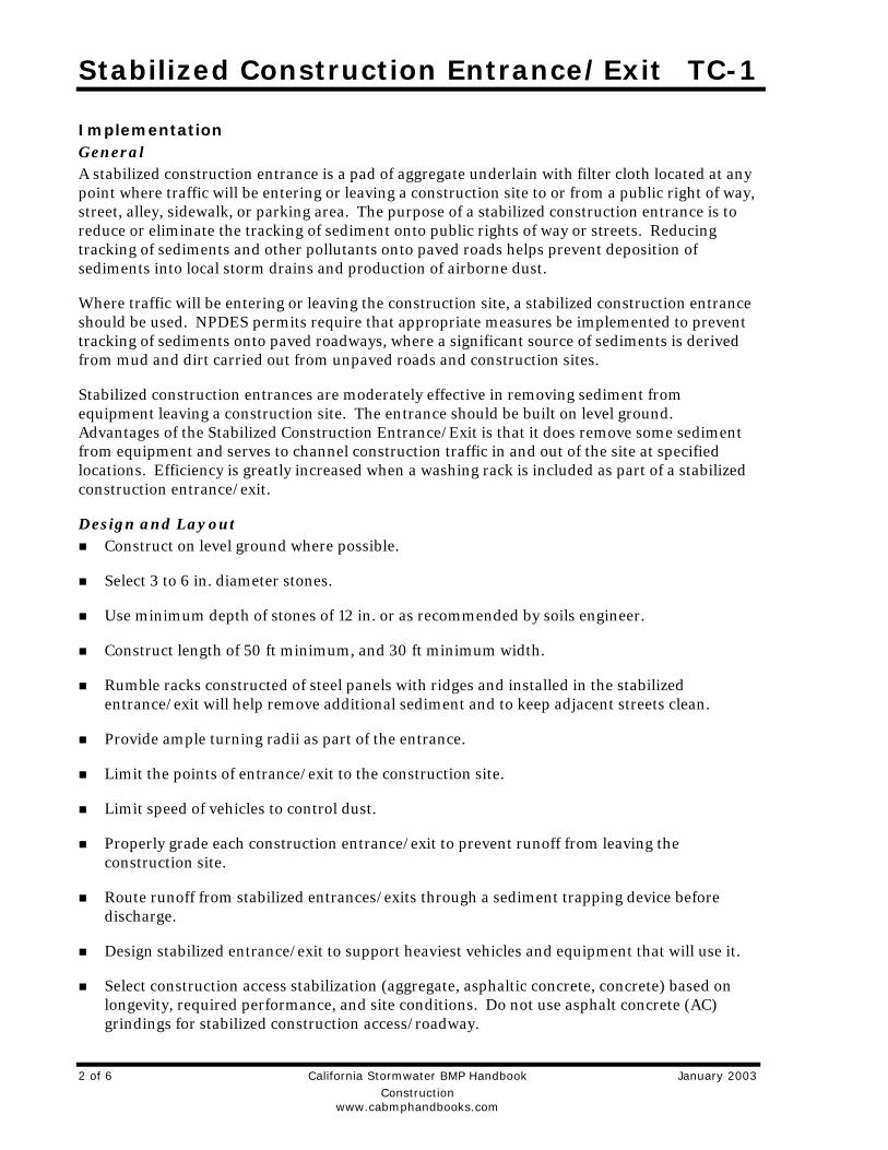
Stabilized Construction Entrance/Exit TC-1
2 of 6 California Stormwater BMP Handbook January 2003 Construction www.cabmphandbooks.com
Implementation General A stabilized construction entrance is a pad of aggregate underlain with filter cloth located at any point where traffic will be entering or leaving a construction site to or from a public right of way, street, alley, sidewalk, or parking area. The purpose of a stabilized construction entrance is to reduce or eliminate the tracking of sediment onto public rights of way or streets. Reducing tracking of sediments and other pollutants onto paved roads helps prevent deposition of sediments into local storm drains and production of airborne dust.
Where traffic will be entering or leaving the construction site, a stabilized construction entrance should be used. NPDES permits require that appropriate measures be implemented to prevent tracking of sediments onto paved roadways, where a significant source of sediments is derived from mud and dirt carried out from unpaved roads and construction sites.
Stabilized construction entrances are moderately effective in removing sediment from equipment leaving a construction site. The entrance should be built on level ground. Advantages of the Stabilized Construction Entrance/Exit is that it does remove some sediment from equipment and serves to channel construction traffic in and out of the site at specified locations. Efficiency is greatly increased when a washing rack is included as part of a stabilized construction entrance/exit.
Design and Layout Construct on level ground where possible.
Select 3 to 6 in. diameter stones.
Use minimum depth of stones of 12 in. or as recommended by soils engineer.
Construct length of 50 ft minimum, and 30 ft minimum width.
Rumble racks constructed of steel panels with ridges and installed in the stabilized entrance/exit will help remove additional sediment and to keep adjacent streets clean.
Provide ample turning radii as part of the entrance.
Limit the points of entrance/exit to the construction site.
Limit speed of vehicles to control dust.
Properly grade each construction entrance/exit to prevent runoff from leaving the construction site.
Route runoff from stabilized entrances/exits through a sediment trapping device before discharge.
Design stabilized entrance/exit to support heaviest vehicles and equipment that will use it.
Select construction access stabilization (aggregate, asphaltic concrete, concrete) based on longevity, required performance, and site conditions. Do not use asphalt concrete (AC) grindings for stabilized construction access/roadway.
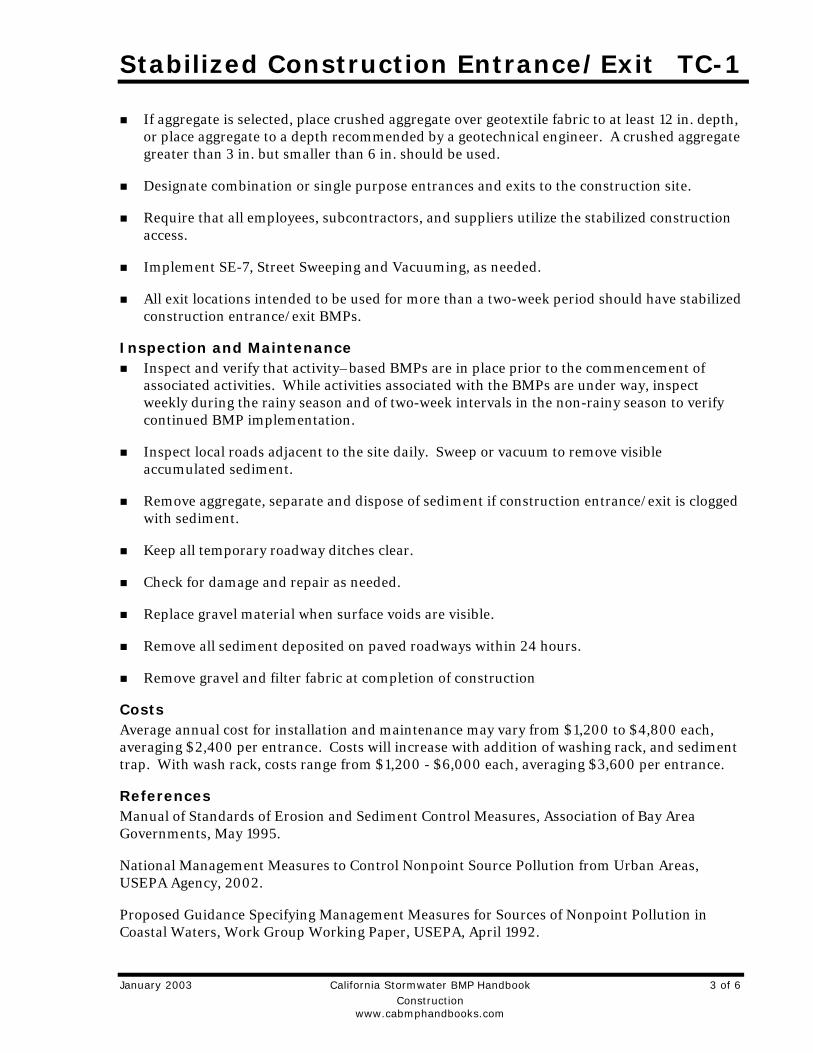
Stabilized Construction Entrance/Exit TC-1
January 2003 California Stormwater BMP Handbook 3 of 6 Construction www.cabmphandbooks.com
If aggregate is selected, place crushed aggregate over geotextile fabric to at least 12 in. depth, or place aggregate to a depth recommended by a geotechnical engineer. A crushed aggregate greater than 3 in. but smaller than 6 in. should be used.
Designate combination or single purpose entrances and exits to the construction site.
Require that all employees, subcontractors, and suppliers utilize the stabilized construction access.
Implement SE-7, Street Sweeping and Vacuuming, as needed.
All exit locations intended to be used for more than a two-week period should have stabilized construction entrance/exit BMPs.
Inspection and Maintenance Inspect and verify that activity–based BMPs are in place prior to the commencement of
associated activities. While activities associated with the BMPs are under way, inspect weekly during the rainy season and of two-week intervals in the non-rainy season to verify continued BMP implementation.
Inspect local roads adjacent to the site daily. Sweep or vacuum to remove visible accumulated sediment.
Remove aggregate, separate and dispose of sediment if construction entrance/exit is clogged with sediment.
Keep all temporary roadway ditches clear.
Check for damage and repair as needed.
Replace gravel material when surface voids are visible.
Remove all sediment deposited on paved roadways within 24 hours.
Remove gravel and filter fabric at completion of construction
Costs Average annual cost for installation and maintenance may vary from $1,200 to $4,800 each, averaging $2,400 per entrance. Costs will increase with addition of washing rack, and sediment trap. With wash rack, costs range from $1,200 - $6,000 each, averaging $3,600 per entrance.
References Manual of Standards of Erosion and Sediment Control Measures, Association of Bay Area Governments, May 1995.
National Management Measures to Control Nonpoint Source Pollution from Urban Areas, USEPA Agency, 2002.
Proposed Guidance Specifying Management Measures for Sources of Nonpoint Pollution in Coastal Waters, Work Group Working Paper, USEPA, April 1992.
Stabilized Construction Entrance/Exit TC-1
4 of 6 California Stormwater BMP Handbook January 2003 Construction www.cabmphandbooks.com
Stormwater Quality Handbooks Construction Site Best Management Practices (BMPs) Manual, State of California Department of Transportation (Caltrans), November 2000.
Stormwater Management of the Puget Sound Basin, Technical Manual, Publication #91-75, Washington State Department of Ecology, February 1992.
Virginia Erosion and Sedimentation Control Handbook, Virginia Department of Conservation and Recreation, Division of Soil and Water Conservation, 1991.
Guidance Specifying Management Measures for Nonpoint Pollution in Coastal Waters, EPA 840-B-9-002, USEPA, Office of Water, Washington, DC, 1993.
Water Quality Management Plan for the Lake Tahoe Region, Volume II, Handbook of Management Practices, Tahoe Regional Planning Agency, November 1988.
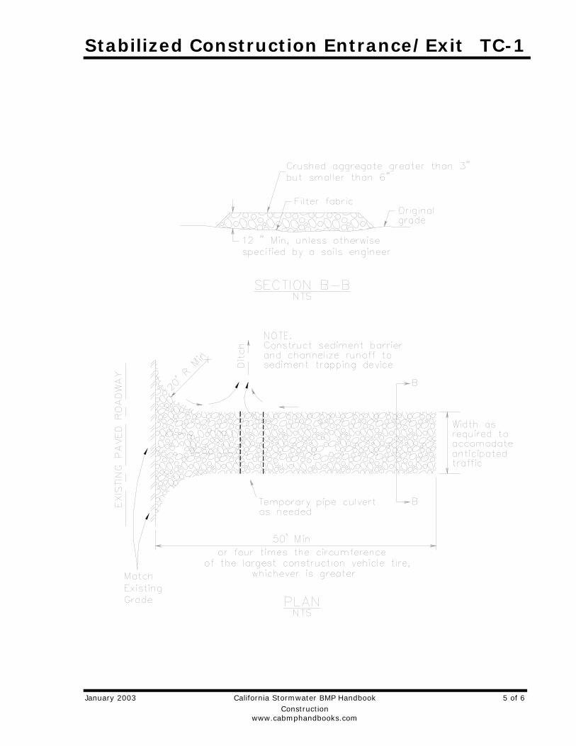
Stabilized Construction Entrance/Exit TC-1
January 2003 California Stormwater BMP Handbook 5 of 6 Construction www.cabmphandbooks.com

Stabilized Construction Entrance/Exit TC-1
6 of 6 California Stormwater BMP Handbook January 2003 Construction www.cabmphandbooks.com
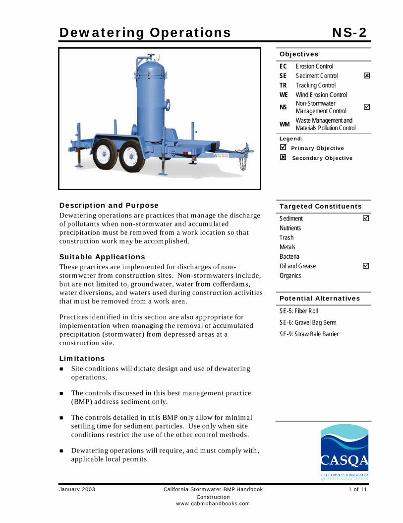
Dewatering Operations NS-2
January 2003 California Stormwater BMP Handbook 1 of 11 Construction www.cabmphandbooks.com
Description and Purpose Dewatering operations are practices that manage the discharge of pollutants when non-stormwater and accumulated precipitation must be removed from a work location so that construction work may be accomplished.
Suitable Applications These practices are implemented for discharges of non-stormwater from construction sites. Non-stormwaters include, but are not limited to, groundwater, water from cofferdams, water diversions, and waters used during construction activities that must be removed from a work area.
Practices identified in this section are also appropriate for implementation when managing the removal of accumulated precipitation (stormwater) from depressed areas at a construction site.
Limitations Site conditions will dictate design and use of dewatering
operations.
The controls discussed in this best management practice (BMP) address sediment only.
The controls detailed in this BMP only allow for minimal settling time for sediment particles. Use only when site conditions restrict the use of the other control methods.
Dewatering operations will require, and must comply with, applicable local permits.
Objectives
EC Erosion Control SE Sediment Control TR Tracking Control WE Wind Erosion Control
NS Non-Stormwater Management Control
WM Waste Management and Materials Pollution Control
Legend:
Primary Objective
Secondary Objective
Targeted Constituents
Sediment Nutrients Trash Metals Bacteria Oil and Grease Organics
Potential Alternatives
SE-5: Fiber Roll
SE-6: Gravel Bag Berm
SE-9: Straw Bale Barrier
NS-2 Dewatering Operations
2 of 11 California Stormwater BMP Handbook January 2003 Construction www.cabmphandbooks.com
Avoid dewatering discharges where possible by using the water for dust control, by infiltration, etc.
Implementation Dewatering non-stormwater cannot be discharged without prior notice to and approval from
the Regional Water Quality Control Board (RWQCB) and local stormwater management agency. This includes stormwater that is co-mingled with groundwater or other non-stormwater sources. Once the discharge is allowed, appropriate BMPs must be implemented to ensure the discharge complies with all permit requirements and regional and watershed-specific requirements.
RWQCB may require a separate NPDES permit prior to the dewatering discharge of non-stormwater. These permits will have specific testing, monitoring, and discharge requirements and can take significant time to obtain.
The flow chart shown in Figure 1 should be utilized to guide dewatering operations.
The owner will coordinate monitoring and permit compliance.
Additional permits or permissions from other agencies may be required for dewatering cofferdams or diversions.
Dewatering discharges must not cause erosion at the discharge point.
A variety of methods can be used to treat water during dewatering operations. Several devices are presented below and provide options to achieve sediment removal. The size of particles present in the sediment and Permit or receiving water limitations on sediment are key considerations for selecting sediment treatment option(s); in some cases, the use of multiple devices may be appropriate.
Sediment Basin (see also SE-2) Description:
A sediment basin is a temporary basin with a controlled release structure that is formed by excavation or construction of an embankment to detain sediment-laden runoff and allow sediment to settle out before discharging. Sediment basins are generally larger than Sediment Traps (SE-3).
Appropriate Applications: Effective for the removal of gravel, sand, silt, some metals that settle out with the sediment,
and trash.
Implementation: Excavation and construction of related facilities is required.
Temporary sediment basins must be fenced if safety is a concern.
Outlet protection is required to prevent erosion at the outfall location.
Dewatering Operations NS-2
January 2003 California Stormwater BMP Handbook 3 of 11 Construction www.cabmphandbooks.com
Maintenance: Maintenance is required for safety fencing, vegetation, embankment, inlet and outfall
structures, as well as other features.
Removal of sediment is required when the storage volume is reduced by one-half.
Sediment Trap (See also SE-3) Description:
A sediment trap is a temporary basin formed by excavation and/or construction of an earthen embankment across a waterway or low drainage area to detain sediment-laden runoff and allow sediment to settle out before discharging. Sediment traps are generally smaller than Sediment Basins (SE-2).
Appropriate Applications: Effective for the removal of large and medium sized particles (sand and gravel) and some metals that settle out with the sediment.
Implementation: Excavation and construction of related facilities is required.
Trap inlets should be located to maximize the travel distance to the trap outlet.
Use rock or vegetation to protect the trap outlets against erosion.
Maintenance: Maintenance is required for vegetation, embankment, inlet and outfall structures, as well as
other features.
Removal of sediment is required when the storage volume is reduced by one-third.

NS-2 Dewatering Operations
4 of 11 California Stormwater BMP Handbook January 2003 Construction www.cabmphandbooks.com
Weir Tanks
Description: A weir tank separates water and waste by using weirs. The configuration of the weirs (over
and under weirs) maximizes the residence time in the tank and determines the waste to be removed from the water, such as oil, grease, and sediments.
Appropriate Applications: The tank removes trash, some settleable solids (gravel, sand, and silt), some visible oil and
grease, and some metals (removed with sediment). To achieve high levels of flow, multiple tanks can be used in parallel. If additional treatment is desired, the tanks can be placed in series or as pre-treatment for other methods.
Implementation: Tanks are delivered to the site by the vendor, who can provide assistance with set-up and
operation.
Tank size will depend on flow volume, constituents of concern, and residency period required. Vendors should be consulted to appropriately size tank.
Maintenance: Periodic cleaning is required based on visual inspection or reduced flow.
Oil and grease disposal must be by licensed waste disposal company.
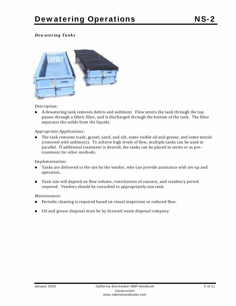
Dewatering Operations NS-2
January 2003 California Stormwater BMP Handbook 5 of 11 Construction www.cabmphandbooks.com
Dewatering Tanks
Description: A dewatering tank removes debris and sediment. Flow enters the tank through the top,
passes through a fabric filter, and is discharged through the bottom of the tank. The filter separates the solids from the liquids.
Appropriate Applications: The tank removes trash, gravel, sand, and silt, some visible oil and grease, and some metals
(removed with sediment). To achieve high levels of flow, multiple tanks can be used in parallel. If additional treatment is desired, the tanks can be placed in series or as pre-treatment for other methods.
Implementation: Tanks are delivered to the site by the vendor, who can provide assistance with set-up and
operation.
Tank size will depend on flow volume, constituents of concern, and residency period required. Vendors should be consulted to appropriately size tank.
Maintenance: Periodic cleaning is required based on visual inspection or reduced flow.
Oil and grease disposal must be by licensed waste disposal company.

NS-2 Dewatering Operations
6 of 11 California Stormwater BMP Handbook January 2003 Construction www.cabmphandbooks.com
Gravity Bag Filter
Description: A gravity bag filter, also referred to as a dewatering bag, is a square or rectangular bag made
of non-woven geotextile fabric that collects sand, silt, and fines.
Appropriate Applications: Effective for the removal of sediments (gravel, sand, and silt). Some metals are removed
with the sediment.
Implementation: Water is pumped into one side of the bag and seeps through the bottom and sides of the bag.
A secondary barrier, such as a rock filter bed or straw/hay bale barrier, is placed beneath and beyond the edges of the bag to capture sediments that escape the bag.
Maintenance: Inspection of the flow conditions, bag condition, bag capacity, and the secondary barrier is
required.
Replace the bag when it no longer filters sediment or passes water at a reasonable rate.
The bag is disposed of offsite.
FLOW
FILTERED WATERPUMP DISCHARGE HOSE
AVAILABLE IN VARIOUSSHAPES AND SIZES FORSEDIMENT CONTAINMENT
DEWATERING BAG
TIE DOWN STRAP
WATER PUMP
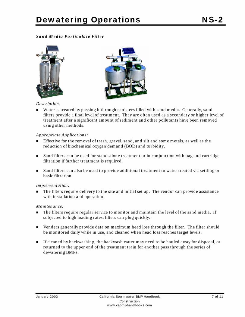
Dewatering Operations NS-2
January 2003 California Stormwater BMP Handbook 7 of 11 Construction www.cabmphandbooks.com
Sand Media Particulate Filter
Description: Water is treated by passing it through canisters filled with sand media. Generally, sand
filters provide a final level of treatment. They are often used as a secondary or higher level of treatment after a significant amount of sediment and other pollutants have been removed using other methods.
Appropriate Applications: Effective for the removal of trash, gravel, sand, and silt and some metals, as well as the
reduction of biochemical oxygen demand (BOD) and turbidity.
Sand filters can be used for stand-alone treatment or in conjunction with bag and cartridge filtration if further treatment is required.
Sand filters can also be used to provide additional treatment to water treated via settling or basic filtration.
Implementation: The filters require delivery to the site and initial set up. The vendor can provide assistance
with installation and operation.
Maintenance: The filters require regular service to monitor and maintain the level of the sand media. If
subjected to high loading rates, filters can plug quickly.
Venders generally provide data on maximum head loss through the filter. The filter should be monitored daily while in use, and cleaned when head loss reaches target levels.
If cleaned by backwashing, the backwash water may need to be hauled away for disposal, or returned to the upper end of the treatment train for another pass through the series of dewatering BMPs.
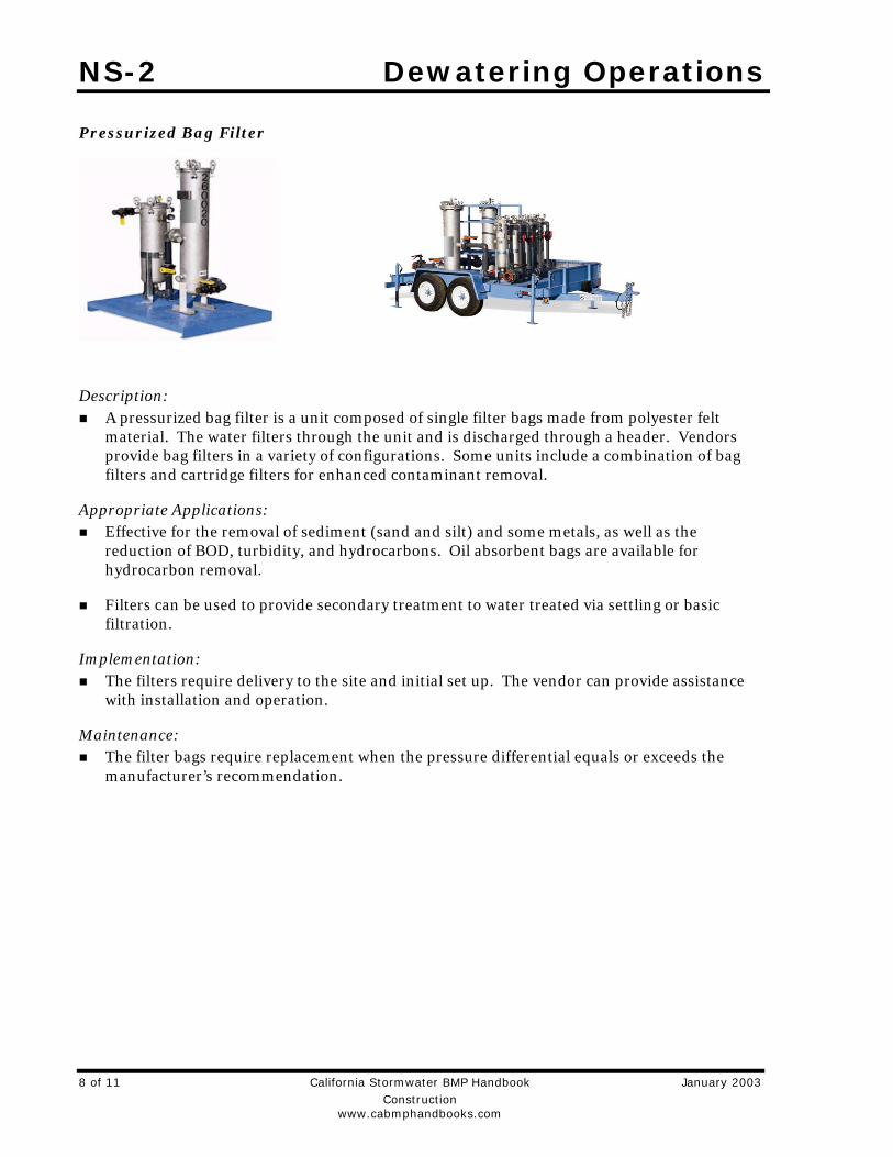
NS-2 Dewatering Operations
8 of 11 California Stormwater BMP Handbook January 2003 Construction www.cabmphandbooks.com
Pressurized Bag Filter
Description: A pressurized bag filter is a unit composed of single filter bags made from polyester felt
material. The water filters through the unit and is discharged through a header. Vendors provide bag filters in a variety of configurations. Some units include a combination of bag filters and cartridge filters for enhanced contaminant removal.
Appropriate Applications: Effective for the removal of sediment (sand and silt) and some metals, as well as the
reduction of BOD, turbidity, and hydrocarbons. Oil absorbent bags are available for hydrocarbon removal.
Filters can be used to provide secondary treatment to water treated via settling or basic filtration.
Implementation: The filters require delivery to the site and initial set up. The vendor can provide assistance
with installation and operation.
Maintenance: The filter bags require replacement when the pressure differential equals or exceeds the
manufacturer’s recommendation.

Dewatering Operations NS-2
January 2003 California Stormwater BMP Handbook 9 of 11 Construction www.cabmphandbooks.com
Cartridge Filter
Description: Cartridge filters provide a high degree of pollutant removal by utilizing a number of
individual cartridges as part of a larger filtering unit. They are often used as a secondary or higher (polishing) level of treatment after a significant amount of sediment and other pollutants are removed. Units come with various cartridge configurations (for use in series with bag filters) or with a larger single cartridge filtration unit (with multiple filters within).
Appropriate Applications: Effective for the removal of sediment (sand, silt, and some clays) and metals, as well as the
reduction of BOD, turbidity, and hydrocarbons. Hydrocarbons can effectively be removed with special resin cartridges.
Filters can be used to provide secondary treatment to water treated via settling or basic filtration.
Implementation: The filters require delivery to the site and initial set up. The vendor can provide assistance.
Maintenance: The cartridges require replacement when the pressure differential equals or exceeds the
manufacturer’s recommendation.
Costs Sediment controls are low to high cost measures depending on the dewatering system that is
selected. Pressurized filters tend to be more expensive than gravity settling, but are often more effective. Simple tanks are generally rented on a long-term basis (one or more months) and can range from $360 per month for a 1,000 gallon tank to $2,660 per month for a 10,000 gallon tank. Mobilization and demobilization costs vary considerably.
Inspection and Maintenance Inspect and verify that activity-based BMPs are in place prior to the commencement of
associated activities. While activities associated with the BMP are under way, inspect weekly during the rainy season and at two-week intervals in the non-rainy season to verify continued BMP implementation.
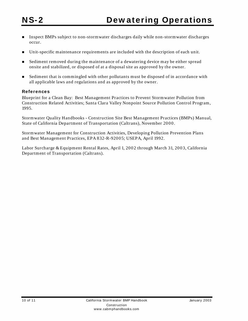
NS-2 Dewatering Operations
10 of 11 California Stormwater BMP Handbook January 2003 Construction www.cabmphandbooks.com
Inspect BMPs subject to non-stormwater discharges daily while non-stormwater discharges occur.
Unit-specific maintenance requirements are included with the description of each unit.
Sediment removed during the maintenance of a dewatering device may be either spread onsite and stabilized, or disposed of at a disposal site as approved by the owner.
Sediment that is commingled with other pollutants must be disposed of in accordance with all applicable laws and regulations and as approved by the owner.
References Blueprint for a Clean Bay: Best Management Practices to Prevent Stormwater Pollution from Construction Related Activities; Santa Clara Valley Nonpoint Source Pollution Control Program, 1995.
Stormwater Quality Handbooks - Construction Site Best Management Practices (BMPs) Manual, State of California Department of Transportation (Caltrans), November 2000.
Stormwater Management for Construction Activities, Developing Pollution Prevention Plans and Best Management Practices, EPA 832-R-92005; USEPA, April 1992.
Labor Surcharge & Equipment Rental Rates, April 1, 2002 through March 31, 2003, California Department of Transportation (Caltrans).
Dewatering Operations NS-2
January 2003 California Stormwater BMP Handbook 11 of 11 Construction www.cabmphandbooks.com
Figure 1 Operations Flow Chart
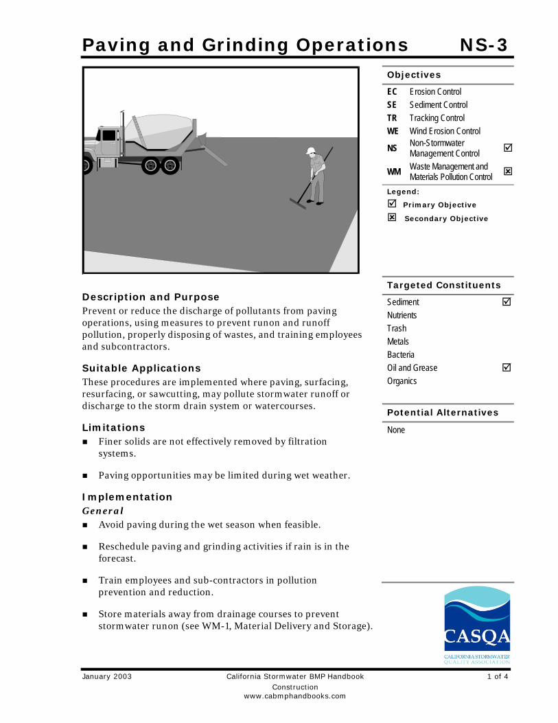
Paving and Grinding Operations NS-3
January 2003 California Stormwater BMP Handbook 1 of 4 Construction www.cabmphandbooks.com
Description and Purpose Prevent or reduce the discharge of pollutants from paving operations, using measures to prevent runon and runoff pollution, properly disposing of wastes, and training employees and subcontractors.
Suitable Applications These procedures are implemented where paving, surfacing, resurfacing, or sawcutting, may pollute stormwater runoff or discharge to the storm drain system or watercourses.
Limitations Finer solids are not effectively removed by filtration
systems.
Paving opportunities may be limited during wet weather.
Implementation General
Avoid paving during the wet season when feasible.
Reschedule paving and grinding activities if rain is in the forecast.
Train employees and sub-contractors in pollution prevention and reduction.
Store materials away from drainage courses to prevent stormwater runon (see WM-1, Material Delivery and Storage).
Objectives
EC Erosion Control SE Sediment Control TR Tracking Control WE Wind Erosion Control
NS Non-Stormwater Management Control
WM Waste Management and Materials Pollution Control
Legend:
Primary Objective
Secondary Objective
Targeted Constituents
Sediment Nutrients Trash Metals Bacteria Oil and Grease Organics
Potential Alternatives
None
NS-3 Paving and Grinding Operations
2 of 4 California Stormwater BMP Handbook January 2003 Construction www.cabmphandbooks.com
Protect drainage courses, particularly in areas with a grade, by employing BMPs to divert runoff or to trap and filter sediment.
If paving involves an onsite mixing plant, follow the stormwater permitting requirements for industrial activities.
Stockpile material removed from roadways away from drain inlets, drainage ditches, and watercourses, These materials should be stored consistent with WM-3, Stockpile Management.
Disposal of PCC and AC waste should be in conformance with WM-8, Concrete Waste Management.
Saw Cutting, Grinding, and Pavement Removal Shovel or vacuum saw-cut slurry and remove from site. Cover or barricade storm drains
during saw cutting to contain slurry.
When paving involves AC, the following steps should be implemented to prevent the discharge of grinding residue, uncompacted or loose AC, tack coats, equipment cleaners, or unrelated paving materials:
- AC grindings, pieces, or chunks used in embankments or shoulder backing must not be allowed to enter any storm drains or watercourses. Install silt fence until structure is stabilized or permanent controls are in place. Examples of temporary perimeter controls can be found in EC-9, Earth Dikes and Drainage Swales; SE-1, Silt Fence; or SE-5, Fiber Rolls.
- Collect and remove all broken asphalt and recycle when practical. Old or spilled asphalt must be recycled or disposed.
- Any AC chunks and pieces used in embankments must be placed above the water table and covered by at least 1 ft of material.
Do not allow saw-cut slurry to enter storm drains or watercourses. Residue from grinding operations should be picked up by means of a vacuum attachment to the grinding machine, should not be allowed to flow across the pavement, and should not be left on the surface of the pavement. See also WM-8, Concrete Waste Management, and WM-10, Liquid Waste Management.
Dig out activities should not be conducted in the rain.
Collect dig out material by mechanical or manual methods. This material may be recycled for use as shoulder backing or base material.
If dig out material cannot be recycled, transport the material back to an approved storage site.
Asphaltic Concrete Paving If paving involves asphaltic cement concrete, follow these steps:
Paving and Grinding Operations NS-3
January 2003 California Stormwater BMP Handbook 3 of 4 Construction www.cabmphandbooks.com
- Do not allow sand or gravel placed over new asphalt to wash into storm drains, streets, or creeks. Vacuum or sweep loose sand and gravel and properly dispose of this waste by referring to WM-5, Solid Waste Management.
- Old asphalt must be disposed of properly. Collect and remove all broken asphalt from the site and recycle whenever possible.
Portland Cement Concrete Paving Do not wash sweepings from exposed aggregate concrete into a storm drain system. Collect
and return to aggregate base stockpile or dispose of properly.
Allow aggregate rinse to settle. Then, either allow rinse water to dry in a temporary pit as described in WM-8, Concrete Waste Management, or pump the water to the sanitary sewer if allowed by the local wastewater authority.
Sealing Operations During chip seal application and sweeping operations, petroleum or petroleum covered
aggregate must not be allowed to enter any storm drain or water courses. Apply temporary perimeter controls until structure is stabilized.
Drainage inlet structures and manholes should be covered with filter fabric during application of seal coat, tack coat, slurry seal, and fog seal.
Seal coat, tack coat, slurry seal, or fog seal should not be applied if rainfall is predicted to occur during the application or curing period.
Paving Equipment Leaks and spills from paving equipment can contain toxic levels of heavy metals and oil and
grease. Place drip pans or absorbent materials under paving equipment when not in use. Clean up spills with absorbent materials rather than burying. See NS-10, Vehicle and Equipment Maintenance, WM-4, Spill Prevention and Control, and WM-10, Liquid Waste Management.
Substances used to coat asphalt transport trucks, and asphalt spreading equipment should not contain soap and should be non-foaming and non-toxic.
Use only non-toxic substances to coat asphalt transport trucks and asphalt spreading equipment.
Paving equipment parked onsite should be parked over plastic to prevent soil contamination.
Clean asphalt coated equipment offsite whenever possible. When cleaning dry, hardened asphalt from equipment, manage hardened asphalt debris as described in WM-5, Solid Waste Management. Any cleaning onsite should follow NS-8, Vehicle and Equipment Cleaning.
NS-3 Paving and Grinding Operations
4 of 4 California Stormwater BMP Handbook January 2003 Construction www.cabmphandbooks.com
Thermoplastic Striping Thermoplastic striper and pre-heater equipment shutoff valves should be inspected to
ensure that they are working properly to prevent leaking thermoplastic from entering drain inlets, the stormwater drainage system, or watercourses.
Pre-heaters should be filled carefully to prevent splashing or spilling of hot thermoplastic. Leave six inches of space at the top of the pre-heater container when filling thermoplastic to allow room for material to move when the vehicle is deadheaded.
Do not pre-heat, transfer, or load thermoplastic near drain inlets or watercourses.
Clean truck beds daily of loose debris and melted thermoplastic. When possible, recycle thermoplastic material.
Raised/Recessed Pavement Marker Application and Removal Do not transfer or load bituminous material near drain inlets, the stormwater drainage
system, or watercourses.
Melting tanks should be loaded with care and not filled to beyond six inches from the top to leave room for splashing when vehicle is deadheaded.
When servicing or filling melting tanks, ensure all pressure is released before removing lids to avoid spills.
On large-scale projects, use mechanical or manual methods to collect excess bituminous material from the roadway after removal of markers.
Costs All of the above are low cost measures.
Inspection and Maintenance Inspect and verify that activity-based BMPs are in place prior to the commencement of
associated activities. While activities associated with the BMP are under way, inspect weekly during the rainy season and at two-week intervals in the non-rainy season to verify continued BMP implementation.
Keep ample supplies of drip pans or absorbent materials onsite.
Inspect and maintain machinery regularly to minimize leaks and drips.
References Blueprint for a Clean Bay: Best Management Practices to Prevent Stormwater Pollution from Construction Related Activities; Santa Clara Valley Nonpoint Source Pollution Control Program, 1995.
Hot Mix Asphalt-Paving Handbook AC 150/5370-14, Appendix I, U.S. Army Corps of Engineers, July 1991.
Stormwater Quality Handbooks - Construction Site Best Management Practices (BMPs) Manual, State of California Department of Transportation (Caltrans), November 2000.
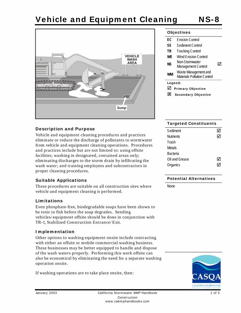
Vehicle and Equipment Cleaning NS-8
January 2003 California Stormwater BMP Handbook 1 of 3 Construction www.cabmphandbooks.com
Description and Purpose Vehicle and equipment cleaning procedures and practices eliminate or reduce the discharge of pollutants to stormwater from vehicle and equipment cleaning operations. Procedures and practices include but are not limited to: using offsite facilities; washing in designated, contained areas only; eliminating discharges to the storm drain by infiltrating the wash water; and training employees and subcontractors in proper cleaning procedures.
Suitable Applications These procedures are suitable on all construction sites where vehicle and equipment cleaning is performed.
Limitations Even phosphate-free, biodegradable soaps have been shown to be toxic to fish before the soap degrades. Sending vehicles/equipment offsite should be done in conjunction with TR-1, Stabilized Construction Entrance/Exit.
Implementation Other options to washing equipment onsite include contracting with either an offsite or mobile commercial washing business. These businesses may be better equipped to handle and dispose of the wash waters properly. Performing this work offsite can also be economical by eliminating the need for a separate washing operation onsite.
If washing operations are to take place onsite, then:
Objectives
EC Erosion Control SE Sediment Control TR Tracking Control WE Wind Erosion Control
NS Non-Stormwater Management Control
WM Waste Management and Materials Pollution Control
Legend:
Primary Objective
Secondary Objective
Targeted Constituents
Sediment Nutrients Trash Metals Bacteria Oil and Grease Organics
Potential Alternatives
None

NS-8 Vehicle and Equipment Cleaning
2 of 3 California Stormwater BMP Handbook January 2003 Construction www.cabmphandbooks.com
Use phosphate-free, biodegradable soaps.
Educate employees and subcontractors on pollution prevention measures.
Do not permit steam cleaning onsite. Steam cleaning can generate significant pollutant concentrates.
Cleaning of vehicles and equipment with soap, solvents or steam should not occur on the project site unless resulting wastes are fully contained and disposed of. Resulting wastes should not be discharged or buried, and must be captured and recycled or disposed according to the requirements of WM-10, Liquid Waste Management or WM-6, Hazardous Waste Management, depending on the waste characteristics. Minimize use of solvents. Use of diesel for vehicle and equipment cleaning is prohibited.
All vehicles and equipment that regularly enter and leave the construction site must be cleaned offsite.
When vehicle and equipment washing and cleaning must occur onsite, and the operation cannot be located within a structure or building equipped with appropriate disposal facilities, the outside cleaning area should have the following characteristics:
- Located away from storm drain inlets, drainage facilities, or watercourses
- Paved with concrete or asphalt and bermed to contain wash waters and to prevent runon and runoff
- Configured with a sump to allow collection and disposal of wash water
- No discharge of wash waters to storm drains or watercourses
- Used only when necessary
When cleaning vehicles and equipment with water:
- Use as little water as possible. High-pressure sprayers may use less water than a hose and should be considered
- Use positive shutoff valve to minimize water usage
- Facility wash racks should discharge to a sanitary sewer, recycle system or other approved discharge system and must not discharge to the storm drainage system, watercourses, or to groundwater
Costs Cleaning vehicles and equipment at an offsite facility may reduce overall costs for vehicle and equipment cleaning by eliminating the need to provide similar services onsite. When onsite cleaning is needed, the cost to establish appropriate facilities is relatively low on larger, long-duration projects, and moderate to high on small, short-duration projects.
Vehicle and Equipment Cleaning NS-8
January 2003 California Stormwater BMP Handbook 3 of 3 Construction www.cabmphandbooks.com
Inspection and Maintenance Inspect and verify that activity-based BMPs are in place prior to the commencement of
associated activities. While activities associated with the BMP are under way, inspect weekly during the rainy season and at two-week intervals in the non-rainy season to verify continued BMP implementation.
Inspect BMPs subject to non-stormwater discharges daily while non-stormwater discharges occur.
Inspection and maintenance is minimal, although some berm repair may be necessary.
Monitor employees and subcontractors throughout the duration of the construction project to ensure appropriate practices are being implemented.
Inspect sump regularly and remove liquids and sediment as needed.
Prohibit employees and subcontractors from washing personal vehicles and equipment on the construction site.
References Stormwater Quality Handbooks - Construction Site Best Management Practices (BMPs) Manual, State of California Department of Transportation (Caltrans), November 2000.
Swisher, R.D. Surfactant Biodegradation, Marcel Decker Corporation, 1987.
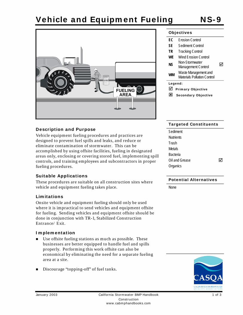
Vehicle and Equipment Fueling NS-9
January 2003 California Stormwater BMP Handbook 1 of 3 Construction www.cabmphandbooks.com
Description and Purpose Vehicle equipment fueling procedures and practices are designed to prevent fuel spills and leaks, and reduce or eliminate contamination of stormwater. This can be accomplished by using offsite facilities, fueling in designated areas only, enclosing or covering stored fuel, implementing spill controls, and training employees and subcontractors in proper fueling procedures.
Suitable Applications These procedures are suitable on all construction sites where vehicle and equipment fueling takes place.
Limitations Onsite vehicle and equipment fueling should only be used where it is impractical to send vehicles and equipment offsite for fueling. Sending vehicles and equipment offsite should be done in conjunction with TR-1, Stabilized Construction Entrance/ Exit.
Implementation Use offsite fueling stations as much as possible. These
businesses are better equipped to handle fuel and spills properly. Performing this work offsite can also be economical by eliminating the need for a separate fueling area at a site.
Discourage “topping-off” of fuel tanks.
Objectives
EC Erosion Control SE Sediment Control TR Tracking Control WE Wind Erosion Control
NS Non-Stormwater Management Control
WM Waste Management and Materials Pollution Control
Legend:
Primary Objective
Secondary Objective
Targeted Constituents
Sediment Nutrients Trash Metals Bacteria Oil and Grease Organics
Potential Alternatives
None
NS-9 Vehicle and Equipment Fueling
2 of 3 California Stormwater BMP Handbook January 2003 Construction www.cabmphandbooks.com
Absorbent spill cleanup materials and spill kits should be available in fueling areas and on fueling trucks, and should be disposed of properly after use.
Drip pans or absorbent pads should be used during vehicle and equipment fueling, unless the fueling is performed over an impermeable surface in a dedicated fueling area.
Use absorbent materials on small spills. Do not hose down or bury the spill. Remove the adsorbent materials promptly and dispose of properly.
Avoid mobile fueling of mobile construction equipment around the site; rather, transport the equipment to designated fueling areas. With the exception of tracked equipment such as bulldozers and large excavators, most vehicles should be able to travel to a designated area with little lost time.
Train employees and subcontractors in proper fueling and cleanup procedures.
When fueling must take place onsite, designate an area away from drainage courses to be used. Fueling areas should be identified in the SWPPP.
Dedicated fueling areas should be protected from stormwater runon and runoff, and should be located at least 50 ft away from downstream drainage facilities and watercourses. Fueling must be performed on level-grade areas.
Protect fueling areas with berms and dikes to prevent runon, runoff, and to contain spills.
Nozzles used in vehicle and equipment fueling should be equipped with an automatic shutoff to control drips. Fueling operations should not be left unattended.
Use vapor recovery nozzles to help control drips as well as air pollution where required by Air Quality Management Districts (AQMD).
Federal, state, and local requirements should be observed for any stationary above ground storage tanks.
Costs All of the above measures are low cost except for the capital costs of above ground tanks that
meet all local environmental, zoning, and fire codes.
Inspection and Maintenance Vehicles and equipment should be inspected each day of use for leaks. Leaks should be
repaired immediately or problem vehicles or equipment should be removed from the project site.
Keep ample supplies of spill cleanup materials onsite.
Immediately clean up spills and properly dispose of contaminated soil and cleanup materials.
Vehicle and Equipment Fueling NS-9
January 2003 California Stormwater BMP Handbook 3 of 3 Construction www.cabmphandbooks.com
References Blueprint for a Clean Bay: Best Management Practices to Prevent Stormwater Pollution from Construction Related Activities; Santa Clara Valley Nonpoint Source Pollution Control Program, 1995.
Coastal Nonpoint Pollution Control Program: Program Development and Approval Guidance, Working Group Working Paper; USEPA, April 1992.
Stormwater Quality Handbooks - Construction Site Best Management Practices (BMPs) Manual, State of California Department of Transportation (Caltrans), November 2000.
Stormwater Management for Construction Activities, Developing Pollution Prevention Plans and Best Management Practices, EPA 832-R-92005; USEPA, April 1992.
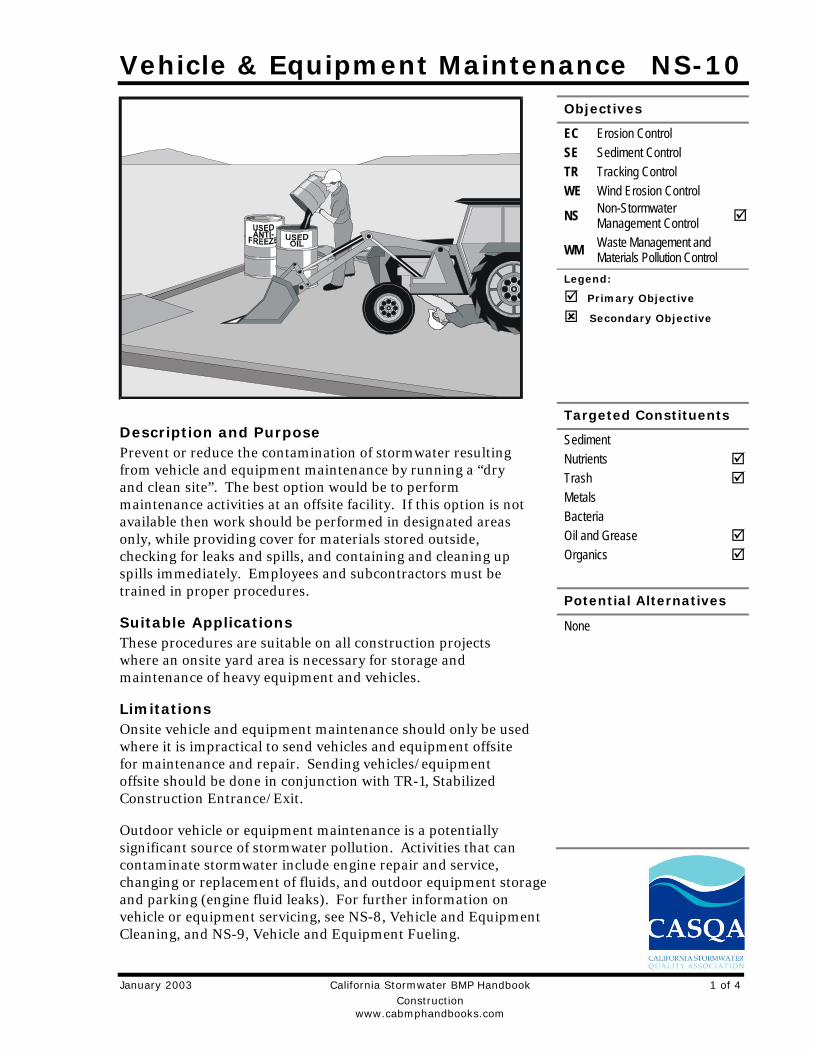
Vehicle & Equipment Maintenance NS-10
January 2003 California Stormwater BMP Handbook 1 of 4 Construction www.cabmphandbooks.com
Description and Purpose Prevent or reduce the contamination of stormwater resulting from vehicle and equipment maintenance by running a “dry and clean site”. The best option would be to perform maintenance activities at an offsite facility. If this option is not available then work should be performed in designated areas only, while providing cover for materials stored outside, checking for leaks and spills, and containing and cleaning up spills immediately. Employees and subcontractors must be trained in proper procedures.
Suitable Applications These procedures are suitable on all construction projects where an onsite yard area is necessary for storage and maintenance of heavy equipment and vehicles.
Limitations Onsite vehicle and equipment maintenance should only be used where it is impractical to send vehicles and equipment offsite for maintenance and repair. Sending vehicles/equipment offsite should be done in conjunction with TR-1, Stabilized Construction Entrance/Exit.
Outdoor vehicle or equipment maintenance is a potentially significant source of stormwater pollution. Activities that can contaminate stormwater include engine repair and service, changing or replacement of fluids, and outdoor equipment storage and parking (engine fluid leaks). For further information on vehicle or equipment servicing, see NS-8, Vehicle and Equipment Cleaning, and NS-9, Vehicle and Equipment Fueling.
Objectives
EC Erosion Control SE Sediment Control TR Tracking Control WE Wind Erosion Control
NS Non-Stormwater Management Control
WM Waste Management and Materials Pollution Control
Legend:
Primary Objective
Secondary Objective
Targeted Constituents
Sediment Nutrients Trash Metals Bacteria Oil and Grease Organics
Potential Alternatives
None
NS-10 Vehicle & Equipment Maintenance
2 of 4 California Stormwater BMP Handbook January 2003 Construction www.cabmphandbooks.com
Implementation Use offsite repair shops as much as possible. These businesses are better equipped to handle
vehicle fluids and spills properly. Performing this work offsite can also be economical by eliminating the need for a separate maintenance area.
If maintenance must occur onsite, use designated areas, located away from drainage courses. Dedicated maintenance areas should be protected from stormwater runon and runoff, and should be located at least 50 ft from downstream drainage facilities and watercourses.
Drip pans or absorbent pads should be used during vehicle and equipment maintenance work that involves fluids, unless the maintenance work is performed over an impermeable surface in a dedicated maintenance area.
Place a stockpile of spill cleanup materials where it will be readily accessible.
All fueling trucks and fueling areas are required to have spill kits and/or use other spill protection devices.
Use adsorbent materials on small spills. Remove the absorbent materials promptly and dispose of properly.
Inspect onsite vehicles and equipment daily at startup for leaks, and repair immediately.
Keep vehicles and equipment clean; do not allow excessive build-up of oil and grease.
Segregate and recycle wastes, such as greases, used oil or oil filters, antifreeze, cleaning solutions, automotive batteries, hydraulic and transmission fluids. Provide secondary containment and covers for these materials if stored onsite.
Train employees and subcontractors in proper maintenance and spill cleanup procedures.
Drip pans or plastic sheeting should be placed under all vehicles and equipment placed on docks, barges, or other structures over water bodies when the vehicle or equipment is planned to be idle for more than 1 hour.
For long-term projects, consider using portable tents or covers over maintenance areas if maintenance cannot be performed offsite.
Consider use of new, alternative greases and lubricants, such as adhesive greases, for chassis lubrication and fifth-wheel lubrication.
Properly dispose of used oils, fluids, lubricants, and spill cleanup materials.
Do not place used oil in a dumpster or pour into a storm drain or watercourse.
Properly dispose of or recycle used batteries.
Do not bury used tires.
Repair leaks of fluids and oil immediately.
Vehicle & Equipment Maintenance NS-10
January 2003 California Stormwater BMP Handbook 3 of 4 Construction www.cabmphandbooks.com
Listed below is further information if you must perform vehicle or equipment maintenance onsite.
Safer Alternative Products Consider products that are less toxic or hazardous than regular products. These products
are often sold under an “environmentally friendly” label.
Consider use of grease substitutes for lubrication of truck fifth-wheels. Follow manufacturers label for details on specific uses.
Consider use of plastic friction plates on truck fifth-wheels in lieu of grease. Follow manufacturers label for details on specific uses.
Waste Reduction Parts are often cleaned using solvents such as trichloroethylene, trichloroethane, or methylene chloride. Many of these cleaners are listed in California Toxic Rule as priority pollutants. These materials are harmful and must not contaminate stormwater. They must be disposed of as a hazardous waste. Reducing the number of solvents makes recycling easier and reduces hazardous waste management costs. Often, one solvent can perform a job as well as two different solvents. Also, if possible, eliminate or reduce the amount of hazardous materials and waste by substituting non-hazardous or less hazardous materials. For example, replace chlorinated organic solvents with non-chlorinated solvents. Non-chlorinated solvents like kerosene or mineral spirits are less toxic and less expensive to dispose of properly. Check the list of active ingredients to see whether it contains chlorinated solvents. The “chlor” term indicates that the solvent is chlorinated. Also, try substituting a wire brush for solvents to clean parts.
Recycling and Disposal Separating wastes allows for easier recycling and may reduce disposal costs. Keep hazardous wastes separate, do not mix used oil solvents, and keep chlorinated solvents (like,-trichloroethane) separate from non-chlorinated solvents (like kerosene and mineral spirits). Promptly transfer used fluids to the proper waste or recycling drums. Don’t leave full drip pans or other open containers lying around. Provide cover and secondary containment until these materials can be removed from the site.
Oil filters can be recycled. Ask your oil supplier or recycler about recycling oil filters.
Do not dispose of extra paints and coatings by dumping liquid onto the ground or throwing it into dumpsters. Allow coatings to dry or harden before disposal into covered dumpsters.
Store cracked batteries in a non-leaking secondary container. Do this with all cracked batteries, even if you think all the acid has drained out. If you drop a battery, treat it as if it is cracked. Put it into the containment area until you are sure it is not leaking.
Costs All of the above are low cost measures. Higher costs are incurred to setup and maintain onsite maintenance areas.

NS-10 Vehicle & Equipment Maintenance
4 of 4 California Stormwater BMP Handbook January 2003 Construction www.cabmphandbooks.com
Inspection and Maintenance Inspect and verify that activity-based BMPs are in place prior to the commencement of
associated activities. While activities associated with the BMP are under way, inspect weekly during the rainy season and at two-week intervals in the non-rainy season to verify continued BMP implementation.
Inspect BMPs subject to non-stormwater discharges daily while non-stormwater discharges occur.
Keep ample supplies of spill cleanup materials onsite.
Maintain waste fluid containers in leak proof condition.
Vehicles and equipment should be inspected on each day of use. Leaks should be repaired immediately or the problem vehicle(s) or equipment should be removed from the project site.
Inspect equipment for damaged hoses and leaky gaskets routinely. Repair or replace as needed.
References Blueprint for a Clean Bay: Best Management Practices to Prevent Stormwater Pollution from Construction Related Activities; Santa Clara Valley Nonpoint Source Pollution Control Program, 1995.
Coastal Nonpoint Pollution Control Program; Program Development and Approval Guidance, Working Group, Working Paper; USEPA, April 1992.
Stormwater Quality Handbooks - Construction Site Best Management Practices (BMPs) Manual, State of California Department of Transportation (Caltrans), November 2000.
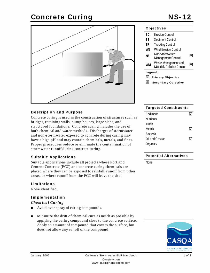
Concrete Curing NS-12
January 2003 California Stormwater BMP Handbook 1 of 2 Construction www.cabmphandbooks.com
Description and Purpose Concrete curing is used in the construction of structures such as bridges, retaining walls, pump houses, large slabs, and structured foundations. Concrete curing includes the use of both chemical and water methods. Discharges of stormwater and non-stormwater exposed to concrete during curing may have a high pH and may contain chemicals, metals, and fines. Proper procedures reduce or eliminate the contamination of stormwater runoff during concrete curing.
Suitable Applications Suitable applications include all projects where Portland Cement Concrete (PCC) and concrete curing chemicals are placed where they can be exposed to rainfall, runoff from other areas, or where runoff from the PCC will leave the site.
Limitations None identified.
Implementation Chemical Curing
Avoid over spray of curing compounds.
Minimize the drift of chemical cure as much as possible by applying the curing compound close to the concrete surface. Apply an amount of compound that covers the surface, but does not allow any runoff of the compound.
Objectives
EC Erosion Control SE Sediment Control TR Tracking Control WE Wind Erosion Control
NS Non-Stormwater Management Control
WM Waste Management and Materials Pollution Control
Legend:
Primary Objective
Secondary Objective
Targeted Constituents
Sediment Nutrients Trash Metals Bacteria Oil and Grease Organics
Potential Alternatives
None

NS-12 Concrete Curing
2 of 2 California Stormwater BMP Handbook January 2003 Construction www.cabmphandbooks.com
Use proper storage and handling techniques for concrete curing compounds. Refer to WM-1, Material Delivery and Storage.
Protect drain inlets prior to the application of curing compounds.
Refer to WM-4, Spill Prevention and Control.
Water Curing for Bridge Decks, Retaining Walls, and other Structures Direct cure water away from inlets and watercourses to collection areas for infiltration or
other means of removal in accordance with all applicable permits.
Collect cure water at the top of slopes and transport or dispose of water in a non-erodible manner. See EC-9 Earth Dikes and Drainage Swales, EC-10, Velocity Dissipation Devices, and EC-11, Slope Drains.
Utilize wet blankets or a similar method that maintains moisture while minimizing the use and possible discharge of water.
Costs All of the above measures are generally low cost.
Inspection and Maintenance Inspect and verify that activity-based BMPs are in place prior to the commencement of
associated activities. While activities associated with the BMP are under way, inspect weekly during the rainy season and at two-week intervals in the non-rainy season to verify continued BMP implementation.
Inspect BMPs subject to non-stormwater discharges daily while non-stormwater discharges occur.
Ensure that employees and subcontractors implement appropriate measures for storage, handling, and use of curing compounds.
Inspect cure containers and spraying equipment for leaks.
References Blue Print for a Clean Bay-Construction-Related Industries: Best Management Practices for Stormwater Pollution Prevention; Santa Clara Valley Non Point Source Pollution Control Program, 1992.
Stormwater Quality Handbooks - Construction Site Best Management Practices (BMPs) Manual, State of California Department of Transportation (Caltrans), November 2000.
Stormwater Management for Construction Activities, Developing Pollution Prevention Plans and Best Management Practices, EPA 832-R-92005; USEPA, April 1992.

Material Delivery and Storage WM-1
January 2003 California Stormwater BMP Handbook 1 of 5 Construction www.cabmphandbooks.com
Description and Purpose Prevent, reduce, or eliminate the discharge of pollutants from material delivery and storage to the stormwater system or watercourses by minimizing the storage of hazardous materials onsite, storing materials in a designated area, installing secondary containment, conducting regular inspections, and training employees and subcontractors.
This best management practice covers only material delivery and storage. For other information on materials, see WM-2, Material Use, or WM-4, Spill Prevention and Control. For information on wastes, see the waste management BMPs in this section.
Suitable Applications These procedures are suitable for use at all construction sites with delivery and storage of the following materials:
Soil stabilizers and binders
Pesticides and herbicides
Fertilizers
Detergents
Plaster
Petroleum products such as fuel, oil, and grease
Asphalt and concrete components
Objectives
EC Erosion Control SE Sediment Control TC Tracking Control WE Wind Erosion Control
NS Non-Stormwater Management Control
WM Waste Management and Materials Pollution Control
Legend:
Primary Objective
Secondary Objective
Targeted Constituents
Sediment Nutrients Trash Metals Bacteria Oil and Grease Organics
Potential Alternatives
None
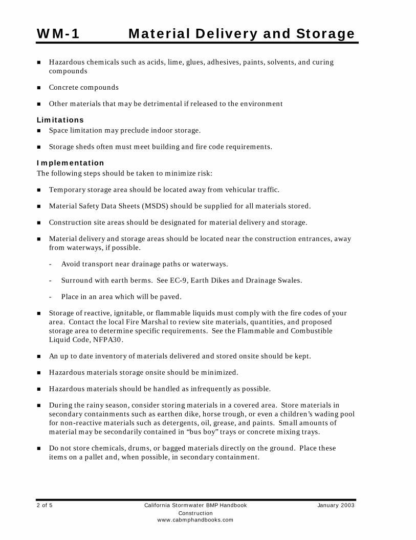
WM-1 Material Delivery and Storage
2 of 5 California Stormwater BMP Handbook January 2003 Construction www.cabmphandbooks.com
Hazardous chemicals such as acids, lime, glues, adhesives, paints, solvents, and curing compounds
Concrete compounds
Other materials that may be detrimental if released to the environment
Limitations Space limitation may preclude indoor storage.
Storage sheds often must meet building and fire code requirements.
Implementation The following steps should be taken to minimize risk:
Temporary storage area should be located away from vehicular traffic.
Material Safety Data Sheets (MSDS) should be supplied for all materials stored.
Construction site areas should be designated for material delivery and storage.
Material delivery and storage areas should be located near the construction entrances, away from waterways, if possible.
- Avoid transport near drainage paths or waterways.
- Surround with earth berms. See EC-9, Earth Dikes and Drainage Swales.
- Place in an area which will be paved.
Storage of reactive, ignitable, or flammable liquids must comply with the fire codes of your area. Contact the local Fire Marshal to review site materials, quantities, and proposed storage area to determine specific requirements. See the Flammable and Combustible Liquid Code, NFPA30.
An up to date inventory of materials delivered and stored onsite should be kept.
Hazardous materials storage onsite should be minimized.
Hazardous materials should be handled as infrequently as possible.
During the rainy season, consider storing materials in a covered area. Store materials in secondary containments such as earthen dike, horse trough, or even a children’s wading pool for non-reactive materials such as detergents, oil, grease, and paints. Small amounts of material may be secondarily contained in “bus boy” trays or concrete mixing trays.
Do not store chemicals, drums, or bagged materials directly on the ground. Place these items on a pallet and, when possible, in secondary containment.
Material Delivery and Storage WM-1
January 2003 California Stormwater BMP Handbook 3 of 5 Construction www.cabmphandbooks.com
If drums must be kept uncovered, store them at a slight angle to reduce ponding of rainwater on the lids to reduce corrosion. Domed plastic covers are inexpensive and snap to the top of drums, preventing water from collecting.
Chemicals should be kept in their original labeled containers.
Employees and subcontractors should be trained on the proper material delivery and storage practices.
Employees trained in emergency spill cleanup procedures must be present when dangerous materials or liquid chemicals are unloaded.
If significant residual materials remain on the ground after construction is complete, properly remove materials and any contaminated soil. See WM-7, Contaminated Soil Management. If the area is to be paved, pave as soon as materials are removed to stabilize the soil.
Material Storage Areas and Practices Liquids, petroleum products, and substances listed in 40 CFR Parts 110, 117, or 302 should
be stored in approved containers and drums and should not be overfilled. Containers and drums should be placed in temporary containment facilities for storage.
A temporary containment facility should provide for a spill containment volume able to contain precipitation from a 25 year storm event, plus the greater of 10% of the aggregate volume of all containers or 100% of the capacity of the largest container within its boundary, whichever is greater.
A temporary containment facility should be impervious to the materials stored therein for a minimum contact time of 72 hours.
A temporary containment facility should be maintained free of accumulated rainwater and spills. In the event of spills or leaks, accumulated rainwater and spills should be collected and placed into drums. These liquids should be handled as a hazardous waste unless testing determines them to be non-hazardous. All collected liquids or non-hazardous liquids should be sent to an approved disposal site.
Sufficient separation should be provided between stored containers to allow for spill cleanup and emergency response access.
Incompatible materials, such as chlorine and ammonia, should not be stored in the same temporary containment facility.
Throughout the rainy season, each temporary containment facility should be covered during non-working days, prior to, and during rain events.
Materials should be stored in their original containers and the original product labels should be maintained in place in a legible condition. Damaged or otherwise illegible labels should be replaced immediately.
WM-1 Material Delivery and Storage
4 of 5 California Stormwater BMP Handbook January 2003 Construction www.cabmphandbooks.com
Bagged and boxed materials should be stored on pallets and should not be allowed to accumulate on the ground. To provide protection from wind and rain throughout the rainy season, bagged and boxed materials should be covered during non-working days and prior to and during rain events.
Stockpiles should be protected in accordance with WM-3, Stockpile Management.
Materials should be stored indoors within existing structures or sheds when available.
Proper storage instructions should be posted at all times in an open and conspicuous location.
An ample supply of appropriate spill clean up material should be kept near storage areas.
Also see WM-6, Hazardous Waste Management, for storing of hazardous materials.
Material Delivery Practices Keep an accurate, up-to-date inventory of material delivered and stored onsite.
Arrange for employees trained in emergency spill cleanup procedures to be present when dangerous materials or liquid chemicals are unloaded.
Spill Cleanup Contain and clean up any spill immediately.
Properly remove and dispose of any hazardous materials or contaminated soil if significant residual materials remain on the ground after construction is complete. See WM-7, Contaminated Soil Management.
See WM-4, Spill Prevention and Control, for spills of chemicals and/or hazardous materials.
Cost The largest cost of implementation may be in the construction of a materials storage area
that is covered and provides secondary containment.
Inspection and Maintenance Inspect and verify that activity–based BMPs are in place prior to the commencement of
associated activities. While activities associated with the BMP are under way, inspect weekly during the rainy season and of two-week intervals in the non-rainy season to verify continued BMP implementation.
Keep an ample supply of spill cleanup materials near the storage area.
Keep storage areas clean, well organized, and equipped with ample cleanup supplies as appropriate for the materials being stored.
Repair or replace perimeter controls, containment structures, covers, and liners as needed to maintain proper function.

Material Delivery and Storage WM-1
January 2003 California Stormwater BMP Handbook 5 of 5 Construction www.cabmphandbooks.com
References Blueprint for a Clean Bay: Best Management Practices to Prevent Stormwater Pollution from Construction Related Activities; Santa Clara Valley Nonpoint Source Pollution Control Program, 1995.
Coastal Nonpoint Pollution Control Program: Program Development and Approval Guidance, Working Group Working Paper; USEPA, April 1992.
Stormwater Quality Handbooks - Construction Site Best Management Practices (BMPs) Manual, State of California Department of Transportation (Caltrans), November 2000.
Stormwater Management for Construction Activities; Developing Pollution Prevention Plans and Best Management Practice, EPA 832-R-92005; USEPA, April 1992.

Material Use WM-2
January 2003 California Stormwater BMP Handbook 1 of 3 Construction www.cabmphandbooks.com
Description and Purpose Prevent or reduce the discharge of pollutants to the storm drain system or watercourses from material use by using alternative products, minimizing hazardous material use onsite, and training employees and subcontractors.
Suitable Applications This BMP is suitable for use at all construction projects. These procedures apply when the following materials are used or prepared onsite:
Pesticides and herbicides
Fertilizers
Detergents
Plaster
Petroleum products such as fuel, oil, and grease
Asphalt and other concrete components
Other hazardous chemicals such as acids, lime, glues, adhesives, paints, solvents, and curing compounds
Concrete compounds
Other materials that may be detrimental if released to the environment
Objectives
EC Erosion Control SE Sediment Control TC Tracking Control WE Wind Erosion Control
NS Non-Stormwater Management Control
WM Waste Management and Materials Pollution Control
Legend:
Primary Objective
Secondary Objective
Targeted Constituents
Sediment Nutrients Trash Metals Bacteria Oil and Grease Organics
Potential Alternatives
None
WM-2 Material Use
2 of 3 California Stormwater BMP Handbook January 2003 Construction www.cabmphandbooks.com
Limitations Safer alternative building and construction products may not be available or suitable in every instance.
Implementation The following steps should be taken to minimize risk:
Minimize use of hazardous materials onsite.
Follow manufacturer instructions regarding uses, protective equipment, ventilation, flammability, and mixing of chemicals.
Train personnel who use pesticides. The California Department of Pesticide Regulation and county agricultural commissioners license pesticide dealers, certify pesticide applicators, and conduct onsite inspections.
Do not over-apply fertilizers, herbicides, and pesticides. Prepare only the amount needed. Follow the recommended usage instructions. Over-application is expensive and environmentally harmful. Unless on steep slopes, till fertilizers into the soil rather than hydro seeding. Apply surface dressings in several smaller applications, as opposed to one large application, to allow time for infiltration and to avoid excess material being carried offsite by runoff. Do not apply these chemicals just before it rains.
Train employees and subcontractors in proper material use.
Supply Material Safety Data Sheets (MSDS) for all materials.
Dispose of latex paint and paint cans, used brushes, rags, absorbent materials, and drop cloths, when thoroughly dry and are no longer hazardous, with other construction debris.
Do not remove the original product label; it contains important safety and disposal information. Use the entire product before disposing of the container.
Mix paint indoors or in a containment area. Never clean paintbrushes or rinse paint containers into a street, gutter, storm drain, or watercourse. Dispose of any paint thinners, residue, and sludge(s) that cannot be recycled, as hazardous waste.
For water-based paint, clean brushes to the extent practicable, and rinse to a drain leading to a sanitary sewer where permitted, or into a concrete washout pit or temporary sediment trap. For oil-based paints, clean brushes to the extent practicable, and filter and reuse thinners and solvents.
Use recycled and less hazardous products when practical. Recycle residual paints, solvents, non-treated lumber, and other materials.
Use materials only where and when needed to complete the construction activity. Use safer alternative materials as much as possible. Reduce or eliminate use of hazardous materials onsite when practical.

Material Use WM-2
January 2003 California Stormwater BMP Handbook 3 of 3 Construction www.cabmphandbooks.com
Require contractors to complete the “Report of Chemical Spray Forms” when spraying herbicides and pesticides.
Keep an ample supply of spill clean up material near use areas. Train employees in spill clean up procedures.
Avoid exposing applied materials to rainfall and runoff unless sufficient time has been allowed for them to dry.
Costs All of the above are low cost measures.
Inspection and Maintenance Inspect and verify that activity–based BMPs are in place prior to the commencement of
associated activities. While activities associated with the BMP are under way, inspect weekly during the rainy season and at two–week intervals in the non-rainy season to verify continued BMP implementation.
Maintenance of this best management practice is minimal.
Spot check employees and subcontractors throughout the job to ensure appropriate practices are being employed.
References Blueprint for a Clean Bay: Best Management Practices to Prevent Stormwater Pollution from Construction Related Activities; Santa Clara Valley Nonpoint Source Pollution Control Program, 1995.
Coastal Nonpoint Pollution Control Program: Program Development and Approval Guidance, Working Group Working Paper; USEPA, April 1992.
Stormwater Quality Handbooks - Construction Site Best Management Practices (BMPs) Manual, State of California Department of Transportation (Caltrans), November 2000.
Stormwater Management for Construction Activities; Developing Pollution Prevention Plans and Best Management Practice, EPA 832-R-92005; USEPA, April 1992.
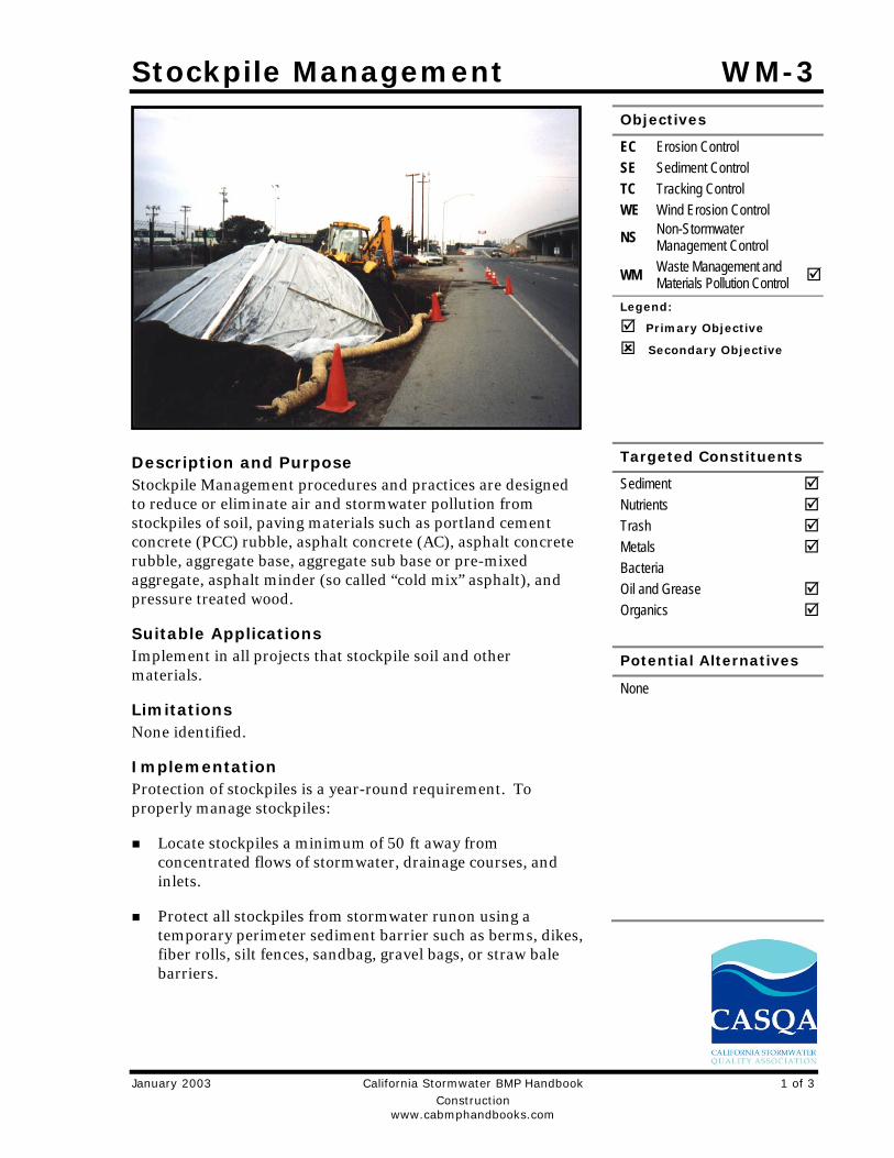
Stockpile Management WM-3
January 2003 California Stormwater BMP Handbook 1 of 3 Construction www.cabmphandbooks.com
Description and Purpose Stockpile Management procedures and practices are designed to reduce or eliminate air and stormwater pollution from stockpiles of soil, paving materials such as portland cement concrete (PCC) rubble, asphalt concrete (AC), asphalt concrete rubble, aggregate base, aggregate sub base or pre-mixed aggregate, asphalt minder (so called “cold mix” asphalt), and pressure treated wood.
Suitable Applications Implement in all projects that stockpile soil and other materials.
Limitations None identified.
Implementation Protection of stockpiles is a year-round requirement. To properly manage stockpiles:
Locate stockpiles a minimum of 50 ft away from concentrated flows of stormwater, drainage courses, and inlets.
Protect all stockpiles from stormwater runon using a temporary perimeter sediment barrier such as berms, dikes, fiber rolls, silt fences, sandbag, gravel bags, or straw bale barriers.
Objectives
EC Erosion Control SE Sediment Control TC Tracking Control WE Wind Erosion Control
NS Non-Stormwater Management Control
WM Waste Management and Materials Pollution Control
Legend:
Primary Objective
Secondary Objective
Targeted Constituents
Sediment Nutrients Trash Metals Bacteria Oil and Grease Organics
Potential Alternatives
None
WM-3 Stockpile Management
2 of 3 California Stormwater BMP Handbook January 2003 Construction www.cabmphandbooks.com
Implement wind erosion control practices as appropriate on all stockpiled material. For specific information, see WE-1, Wind Erosion Control.
Manage stockpiles of contaminated soil in accordance with WM-7, Contaminated Soil Management.
Place bagged materials on pallets and under cover.
Protection of Non-Active Stockpiles Non-active stockpiles of the identified materials should be protected further as follows:
Soil stockpiles During the rainy season, soil stockpiles should be covered or protected with soil stabilization
measures and a temporary perimeter sediment barrier at all times.
During the non-rainy season, soil stockpiles should be covered or protected with a temporary perimeter sediment barrier prior to the onset of precipitation.
Stockpiles of Portland cement concrete rubble, asphalt concrete, asphalt concrete rubble, aggregate base, or aggregate sub base
During the rainy season, the stockpiles should be covered or protected with a temporary perimeter sediment barrier at all times.
During the non-rainy season, the stockpiles should be covered or protected with a temporary perimeter sediment barrier prior to the onset of precipitation.
Stockpiles of “cold mix” During the rainy season, cold mix stockpiles should be placed on and covered with plastic or
comparable material at all times.
During the non-rainy season, cold mix stockpiles should be placed on and covered with plastic or comparable material prior to the onset of precipitation.
Stockpiles/Storage of pressure treated wood with copper, chromium, and arsenic or ammonical, copper, zinc, and arsenate
During the rainy season, treated wood should be covered with plastic or comparable material at all times.
During the non-rainy season, treated wood should be covered with plastic or comparable material at all times and cold mix stockpiles should be placed on and covered with plastic or comparable material prior to the onset of precipitation.
Protection of Active Stockpiles Active stockpiles of the identified materials should be protected further as follows:
All stockpiles should be protected with a temporary linear sediment barrier prior to the onset of precipitation.
Stockpiles of “cold mix” should be placed on and covered with plastic or comparable material prior to the onset of precipitation.
Stockpile Management WM-3
January 2003 California Stormwater BMP Handbook 3 of 3 Construction www.cabmphandbooks.com
Costs All of the above are low cost measures.
Inspection and Maintenance Inspect and verify that activity–based BMPs are in place prior to the commencement of
associated activities. While activities associated with the BMP are under way, inspect weekly during the rainy season and of two-week intervals in the non-rainy season to verify continued BMP implementation
Repair and/or replace perimeter controls and covers as needed to keep them functioning properly.
References Stormwater Quality Handbooks - Construction Site Best Management Practices (BMPs) Manual, State of California Department of Transportation (Caltrans), November 2000.
Spill Prevention and Control WM-4
January 2003 California Stormwater BMP Handbook 1 of 6 Construction www.cabmphandbooks.com
Description and Purpose Prevent or reduce the discharge of pollutants to drainage systems or watercourses from leaks and spills by reducing the chance for spills, stopping the source of spills, containing and cleaning up spills, properly disposing of spill materials, and training employees.
This best management practice covers only spill prevention and control. However, WM-1, Materials Delivery and Storage, and WM-2, Material Use, also contain useful information, particularly on spill prevention. For information on wastes, see the waste management BMPs in this section.
Suitable Applications This BMP is suitable for all construction projects. Spill control procedures are implemented anytime chemicals or hazardous substances are stored on the construction site, including the following materials:
Soil stabilizers/binders
Dust palliatives
Herbicides
Growth inhibitors
Fertilizers
Deicing/anti-icing chemicals
Objectives
EC Erosion Control SE Sediment Control TC Tracking Control WE Wind Erosion Control
NS Non-Stormwater Management Control
WM Waste Management and Materials Pollution Control
Legend:
Primary Objective
Secondary Objective
Targeted Constituents
Sediment Nutrients Trash Metals Bacteria Oil and Grease Organics
Potential Alternatives
None
Spill Prevention and Control WM-4
2 of 6 California Stormwater BMP Handbook January 2003 Construction www.cabmphandbooks.com
Fuels
Lubricants
Other petroleum distillates
Limitations In some cases it may be necessary to use a private spill cleanup company.
This BMP applies to spills caused by the contractor and subcontractors.
Procedures and practices presented in this BMP are general. Contractor should identify appropriate practices for the specific materials used or stored onsite
Implementation The following steps will help reduce the stormwater impacts of leaks and spills:
Education Be aware that different materials pollute in different amounts. Make sure that each
employee knows what a “significant spill” is for each material they use, and what is the appropriate response for “significant” and “insignificant” spills.
Educate employees and subcontractors on potential dangers to humans and the environment from spills and leaks.
Hold regular meetings to discuss and reinforce appropriate disposal procedures (incorporate into regular safety meetings).
Establish a continuing education program to indoctrinate new employees.
Have contractor’s superintendent or representative oversee and enforce proper spill prevention and control measures.
General Measures To the extent that the work can be accomplished safely, spills of oil, petroleum products,
substances listed under 40 CFR parts 110,117, and 302, and sanitary and septic wastes should be contained and cleaned up immediately.
Store hazardous materials and wastes in covered containers and protect from vandalism.
Place a stockpile of spill cleanup materials where it will be readily accessible.
Train employees in spill prevention and cleanup.
Designate responsible individuals to oversee and enforce control measures.
Spills should be covered and protected from stormwater runon during rainfall to the extent that it doesn’t compromise clean up activities.
Do not bury or wash spills with water.
Spill Prevention and Control WM-4
January 2003 California Stormwater BMP Handbook 3 of 6 Construction www.cabmphandbooks.com
Store and dispose of used clean up materials, contaminated materials, and recovered spill material that is no longer suitable for the intended purpose in conformance with the provisions in applicable BMPs.
Do not allow water used for cleaning and decontamination to enter storm drains or watercourses. Collect and dispose of contaminated water in accordance with WM-10, Liquid Waste Management.
Contain water overflow or minor water spillage and do not allow it to discharge into drainage facilities or watercourses.
Place proper storage, cleanup, and spill reporting instructions for hazardous materials stored or used on the project site in an open, conspicuous, and accessible location.
Keep waste storage areas clean, well organized, and equipped with ample cleanup supplies as appropriate for the materials being stored. Perimeter controls, containment structures, covers, and liners should be repaired or replaced as needed to maintain proper function.
Cleanup Clean up leaks and spills immediately.
Use a rag for small spills on paved surfaces, a damp mop for general cleanup, and absorbent material for larger spills. If the spilled material is hazardous, then the used cleanup materials are also hazardous and must be sent to either a certified laundry (rags) or disposed of as hazardous waste.
Never hose down or bury dry material spills. Clean up as much of the material as possible and dispose of properly. See the waste management BMPs in this section for specific information.
Minor Spills Minor spills typically involve small quantities of oil, gasoline, paint, etc. which can be
controlled by the first responder at the discovery of the spill.
Use absorbent materials on small spills rather than hosing down or burying the spill.
Absorbent materials should be promptly removed and disposed of properly.
Follow the practice below for a minor spill:
- Contain the spread of the spill.
- Recover spilled materials.
- Clean the contaminated area and properly dispose of contaminated materials.
Semi-Significant Spills Semi-significant spills still can be controlled by the first responder along with the aid of
other personnel such as laborers and the foreman, etc. This response may require the cessation of all other activities.

Spill Prevention and Control WM-4
4 of 6 California Stormwater BMP Handbook January 2003 Construction www.cabmphandbooks.com
Spills should be cleaned up immediately:
- Contain spread of the spill.
- Notify the project foreman immediately.
- If the spill occurs on paved or impermeable surfaces, clean up using "dry" methods (absorbent materials, cat litter and/or rags). Contain the spill by encircling with absorbent materials and do not let the spill spread widely.
- If the spill occurs in dirt areas, immediately contain the spill by constructing an earthen dike. Dig up and properly dispose of contaminated soil.
- If the spill occurs during rain, cover spill with tarps or other material to prevent contaminating runoff.
Significant/Hazardous Spills For significant or hazardous spills that cannot be controlled by personnel in the immediate
vicinity, the following steps should be taken:
- Notify the local emergency response by dialing 911. In addition to 911, the contractor will notify the proper county officials. It is the contractor's responsibility to have all emergency phone numbers at the construction site.
- Notify the Governor's Office of Emergency Services Warning Center, (916) 845-8911.
- For spills of federal reportable quantities, in conformance with the requirements in 40 CFR parts 110,119, and 302, the contractor should notify the National Response Center at (800) 424-8802.
- Notification should first be made by telephone and followed up with a written report.
- The services of a spills contractor or a Haz-Mat team should be obtained immediately. Construction personnel should not attempt to clean up until the appropriate and qualified staffs have arrived at the job site.
- Other agencies which may need to be consulted include, but are not limited to, the Fire Department, the Public Works Department, the Coast Guard, the Highway Patrol, the City/County Police Department, Department of Toxic Substances, California Division of Oil and Gas, Cal/OSHA, etc.
Reporting Report significant spills to local agencies, such as the Fire Department; they can assist in
cleanup.
Federal regulations require that any significant oil spill into a water body or onto an adjoining shoreline be reported to the National Response Center (NRC) at 800-424-8802 (24 hours).
Use the following measures related to specific activities:

Spill Prevention and Control WM-4
January 2003 California Stormwater BMP Handbook 5 of 6 Construction www.cabmphandbooks.com
Vehicle and Equipment Maintenance If maintenance must occur onsite, use a designated area and a secondary containment,
located away from drainage courses, to prevent the runon of stormwater and the runoff of spills.
Regularly inspect onsite vehicles and equipment for leaks and repair immediately
Check incoming vehicles and equipment (including delivery trucks, and employee and subcontractor vehicles) for leaking oil and fluids. Do not allow leaking vehicles or equipment onsite.
Always use secondary containment, such as a drain pan or drop cloth, to catch spills or leaks when removing or changing fluids.
Place drip pans or absorbent materials under paving equipment when not in use.
Use absorbent materials on small spills rather than hosing down or burying the spill. Remove the absorbent materials promptly and dispose of properly.
Promptly transfer used fluids to the proper waste or recycling drums. Don’t leave full drip pans or other open containers lying around
Oil filters disposed of in trashcans or dumpsters can leak oil and pollute stormwater. Place the oil filter in a funnel over a waste oil-recycling drum to drain excess oil before disposal. Oil filters can also be recycled. Ask the oil supplier or recycler about recycling oil filters.
Store cracked batteries in a non-leaking secondary container. Do this with all cracked batteries even if you think all the acid has drained out. If you drop a battery, treat it as if it is cracked. Put it into the containment area until you are sure it is not leaking.
Vehicle and Equipment Fueling If fueling must occur onsite, use designate areas, located away from drainage courses, to
prevent the runon of stormwater and the runoff of spills.
Discourage “topping off” of fuel tanks.
Always use secondary containment, such as a drain pan, when fueling to catch spills/ leaks.
Costs Prevention of leaks and spills is inexpensive. Treatment and/ or disposal of contaminated soil or water can be quite expensive.
Inspection and Maintenance Inspect and verify that activity–based BMPs are in place prior to the commencement of
associated activities. While activities associated with the BMP are under way, inspect weekly during the rainy season and of two-week intervals in the non-rainy season to verify continued BMP implementation.
Inspect BMPs subject to non-stormwater discharge daily while non-stormwater discharges occur.
Spill Prevention and Control WM-4
6 of 6 California Stormwater BMP Handbook January 2003 Construction www.cabmphandbooks.com
Keep ample supplies of spill control and cleanup materials onsite, near storage, unloading, and maintenance areas.
Update your spill prevention and control plan and stock cleanup materials as changes occur in the types of chemicals onsite.
References Blueprint for a Clean Bay: Best Management Practices to Prevent Stormwater Pollution from Construction Related Activities; Santa Clara Valley Nonpoint Source Pollution Control Program, 1995.
Stormwater Quality Handbooks - Construction Site Best Management Practices (BMPs) Manual, State of California Department of Transportation (Caltrans), November 2000.
Stormwater Management for Construction Activities; Developing Pollution Prevention Plans and Best Management Practice, EPA 832-R-92005; USEPA, April 1992.

Solid Waste Management WM-5
January 2003 California Stormwater BMP Handbook 1 of 4 Construction www.cabmphandbooks.com
Description and Purpose Solid waste management procedures and practices are designed to prevent or reduce the discharge of pollutants to stormwater from solid or construction waste by providing designated waste collection areas and containers, arranging for regular disposal, and training employees and subcontractors.
Suitable Applications This BMP is suitable for construction sites where the following wastes are generated or stored:
Solid waste generated from trees and shrubs removed during land clearing, demolition of existing structures (rubble), and building construction
Packaging materials including wood, paper, and plastic
Scrap or surplus building materials including scrap metals, rubber, plastic, glass pieces and masonry products
Domestic wastes including food containers such as beverage cans, coffee cups, paper bags, plastic wrappers, and cigarettes
Construction wastes including brick, mortar, timber, steel and metal scraps, pipe and electrical cuttings, non-hazardous equipment parts, styrofoam and other materials used to transport and package construction materials
Objectives
EC Erosion Control SE Sediment Control TC Tracking Control WE Wind Erosion Control
NS Non-Stormwater Management Control
WM Waste Management and Materials Pollution Control
Legend:
Primary Objective
Secondary Objective
Targeted Constituents
Sediment Nutrients Trash Metals Bacteria Oil and Grease Organics
Potential Alternatives
None

WM-5 Solid Waste Management
2 of 4 California Stormwater BMP Handbook January 2003 Construction www.cabmphandbooks.com
Highway planting wastes, including vegetative material, plant containers, and packaging materials
Limitations Temporary stockpiling of certain construction wastes may not necessitate stringent drainage related controls during the non-rainy season or in desert areas with low rainfall.
Implementation The following steps will help keep a clean site and reduce stormwater pollution:
Select designated waste collection areas onsite.
Inform trash-hauling contractors that you will accept only watertight dumpsters for onsite use. Inspect dumpsters for leaks and repair any dumpster that is not watertight.
Locate containers in a covered area or in a secondary containment.
Provide an adequate number of containers with lids or covers that can be placed over the container to keep rain out or to prevent loss of wastes when it is windy.
Plan for additional containers and more frequent pickup during the demolition phase of construction.
Collect site trash daily, especially during rainy and windy conditions.
Remove this solid waste promptly since erosion and sediment control devices tend to collect litter.
Make sure that toxic liquid wastes (used oils, solvents, and paints) and chemicals (acids, pesticides, additives, curing compounds) are not disposed of in dumpsters designated for construction debris.
Do not hose out dumpsters on the construction site. Leave dumpster cleaning to the trash hauling contractor.
Arrange for regular waste collection before containers overflow.
Clean up immediately if a container does spill.
Make sure that construction waste is collected, removed, and disposed of only at authorized disposal areas.
Education Have the contractor’s superintendent or representative oversee and enforce proper solid
waste management procedures and practices.
Instruct employees and subcontractors on identification of solid waste and hazardous waste.
Educate employees and subcontractors on solid waste storage and disposal procedures.

Solid Waste Management WM-5
January 2003 California Stormwater BMP Handbook 3 of 4 Construction www.cabmphandbooks.com
Hold regular meetings to discuss and reinforce disposal procedures (incorporate into regular safety meetings).
Require that employees and subcontractors follow solid waste handling and storage procedures.
Prohibit littering by employees, subcontractors, and visitors.
Minimize production of solid waste materials wherever possible.
Collection, Storage, and Disposal Littering on the project site should be prohibited.
To prevent clogging of the storm drainage system, litter and debris removal from drainage grates, trash racks, and ditch lines should be a priority.
Trash receptacles should be provided in the contractor’s yard, field trailer areas, and at locations where workers congregate for lunch and break periods.
Litter from work areas within the construction limits of the project site should be collected and placed in watertight dumpsters at least weekly, regardless of whether the litter was generated by the contractor, the public, or others. Collected litter and debris should not be placed in or next to drain inlets, stormwater drainage systems, or watercourses.
Dumpsters of sufficient size and number should be provided to contain the solid waste generated by the project.
Full dumpsters should be removed from the project site and the contents should be disposed of by the trash hauling contractor.
Construction debris and waste should be removed from the site biweekly or more frequently as needed.
Construction material visible to the public should be stored or stacked in an orderly manner.
Stormwater runon should be prevented from contacting stored solid waste through the use of berms, dikes, or other temporary diversion structures or through the use of measures to elevate waste from site surfaces.
Solid waste storage areas should be located at least 50 ft from drainage facilities and watercourses and should not be located in areas prone to flooding or ponding.
Except during fair weather, construction and highway planting waste not stored in watertight dumpsters should be securely covered from wind and rain by covering the waste with tarps or plastic.
Segregate potentially hazardous waste from non-hazardous construction site waste.
Make sure that toxic liquid wastes (used oils, solvents, and paints) and chemicals (acids, pesticides, additives, curing compounds) are not disposed of in dumpsters designated for construction debris.

WM-5 Solid Waste Management
4 of 4 California Stormwater BMP Handbook January 2003 Construction www.cabmphandbooks.com
For disposal of hazardous waste, see WM-6, Hazardous Waste Management. Have hazardous waste hauled to an appropriate disposal and/or recycling facility.
Salvage or recycle useful vegetation debris, packaging and surplus building materials when practical. For example, trees and shrubs from land clearing can be used as a brush barrier, or converted into wood chips, then used as mulch on graded areas. Wood pallets, cardboard boxes, and construction scraps can also be recycled.
Costs All of the above are low cost measures.
Inspection and Maintenance Inspect and verify that activity–based BMPs are in place prior to the commencement of
associated activities. While activities associated with the BMP are under way, inspect weekly during the rainy season and of two-week intervals in the non-rainy season to verify continued BMP implementation.
Inspect BMPs subject to non-stormwater discharge daily while non-stormwater discharges occur
Inspect construction waste area regularly.
Arrange for regular waste collection.
References Processes, Procedures and Methods to Control Pollution Resulting from All Construction Activity, 430/9-73-007, USEPA, 1973.
Stormwater Quality Handbooks - Construction Site Best Management Practices (BMPs) Manual, State of California Department of Transportation (Caltrans), November 2000.
Stormwater Management for Construction Activities; Developing Pollution Prevention Plans and Best Management Practice, EPA 832-R-92005; USEPA, April 1992.
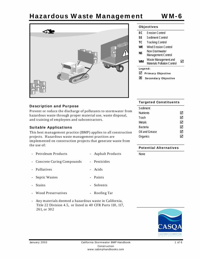
Hazardous Waste Management WM-6
January 2003 California Stormwater BMP Handbook 1 of 6 Construction www.cabmphandbooks.com
Description and Purpose Prevent or reduce the discharge of pollutants to stormwater from hazardous waste through proper material use, waste disposal, and training of employees and subcontractors.
Suitable Applications This best management practice (BMP) applies to all construction projects. Hazardous waste management practices are implemented on construction projects that generate waste from the use of:
Objectives
EC Erosion Control SE Sediment Control TC Tracking Control WE Wind Erosion Control
NS Non-Stormwater Management Control
WM Waste Management and Materials Pollution Control
Legend:
Primary Objective
Secondary Objective
Targeted Constituents
Sediment Nutrients Trash Metals Bacteria Oil and Grease Organics
Potential Alternatives
None - Petroleum Products - Asphalt Products
- Concrete Curing Compounds - Pesticides
- Palliatives - Acids
- Septic Wastes - Paints
- Stains - Solvents
- Wood Preservatives - Roofing Tar
- Any materials deemed a hazardous waste in California, Title 22 Division 4.5, or listed in 40 CFR Parts 110, 117, 261, or 302
Hazardous Waste Management WM-6
2 of 6 California Stormwater BMP Handbook January 2003 Construction www.cabmphandbooks.com
In addition, sites with existing structures may contain wastes, which must be disposed of in accordance with federal, state, and local regulations. These wastes include:
Sandblasting grit mixed with lead-, cadmium-, or chromium-based paints
Asbestos
PCBs (particularly in older transformers)
Limitations Hazardous waste that cannot be reused or recycled must be disposed of by a licensed
hazardous waste hauler.
Nothing in this BMP relieves the contractor from responsibility for compliance with federal, state, and local laws regarding storage, handling, transportation, and disposal of hazardous wastes.
This BMP does not cover aerially deposited lead (ADL) soils. For ADL soils refer to WM-7, Contaminated Soil Management.
Implementation The following steps will help reduce stormwater pollution from hazardous wastes:
Material Use Wastes should be stored in sealed containers constructed of a suitable material and should
be labeled as required by Title 22 CCR, Division 4.5 and 49 CFR Parts 172, 173, 178, and 179.
All hazardous waste should be stored, transported, and disposed as required in Title 22 CCR, Division 4.5 and 49 CFR 261-263.
Waste containers should be stored in temporary containment facilities that should comply with the following requirements:
- Temporary containment facility should provide for a spill containment volume equal to 1.5 times the volume of all containers able to contain precipitation from a 25 year storm event, plus the greater of 10% of the aggregate volume of all containers or 100% of the capacity of the largest tank within its boundary, whichever is greater.
- Temporary containment facility should be impervious to the materials stored there for a minimum contact time of 72 hours.
- Temporary containment facilities should be maintained free of accumulated rainwater and spills. In the event of spills or leaks, accumulated rainwater and spills should be placed into drums after each rainfall. These liquids should be handled as a hazardous waste unless testing determines them to be non-hazardous. Non-hazardous liquids should be sent to an approved disposal site.
- Sufficient separation should be provided between stored containers to allow for spill cleanup and emergency response access.
Hazardous Waste Management WM-6
January 2003 California Stormwater BMP Handbook 3 of 6 Construction www.cabmphandbooks.com
- Incompatible materials, such as chlorine and ammonia, should not be stored in the same temporary containment facility.
- Throughout the rainy season, temporary containment facilities should be covered during non-working days, and prior to rain events. Covered facilities may include use of plastic tarps for small facilities or constructed roofs with overhangs.
Drums should not be overfilled and wastes should not be mixed.
Unless watertight, containers of dry waste should be stored on pallets.
Do not over-apply herbicides and pesticides. Prepare only the amount needed. Follow the recommended usage instructions. Over application is expensive and environmentally harmful. Apply surface dressings in several smaller applications, as opposed to one large application. Allow time for infiltration and avoid excess material being carried offsite by runoff. Do not apply these chemicals just before it rains. People applying pesticides must be certified in accordance with federal and state regulations.
Paint brushes and equipment for water and oil based paints should be cleaned within a contained area and should not be allowed to contaminate site soils, watercourses, or drainage systems. Waste paints, thinners, solvents, residues, and sludges that cannot be recycled or reused should be disposed of as hazardous waste. When thoroughly dry, latex paint and paint cans, used brushes, rags, absorbent materials, and drop cloths should be disposed of as solid waste.
Do not clean out brushes or rinse paint containers into the dirt, street, gutter, storm drain, or stream. “Paint out” brushes as much as possible. Rinse water-based paints to the sanitary sewer. Filter and reuse thinners and solvents. Dispose of excess oil-based paints and sludge as hazardous waste.
The following actions should be taken with respect to temporary contaminant:
- Ensure that adequate hazardous waste storage volume is available.
- Ensure that hazardous waste collection containers are conveniently located.
- Designate hazardous waste storage areas onsite away from storm drains or watercourses and away from moving vehicles and equipment to prevent accidental spills.
- Minimize production or generation of hazardous materials and hazardous waste on the job site.
- Use containment berms in fueling and maintenance areas and where the potential for spills is high.
- Segregate potentially hazardous waste from non-hazardous construction site debris.
- Keep liquid or semi-liquid hazardous waste in appropriate containers (closed drums or similar) and under cover.
Hazardous Waste Management WM-6
4 of 6 California Stormwater BMP Handbook January 2003 Construction www.cabmphandbooks.com
- Clearly label all hazardous waste containers with the waste being stored and the date of accumulation.
- Place hazardous waste containers in secondary containment.
- Do not allow potentially hazardous waste materials to accumulate on the ground.
- Do not mix wastes.
- Use all of the product before disposing of the container.
- Do not remove the original product label; it contains important safety and disposal information.
Waste Recycling Disposal Select designated hazardous waste collection areas onsite.
Hazardous materials and wastes should be stored in covered containers and protected from vandalism.
Place hazardous waste containers in secondary containment.
Do not mix wastes, this can cause chemical reactions, making recycling impossible and complicating disposal.
Recycle any useful materials such as used oil or water-based paint.
Make sure that toxic liquid wastes (used oils, solvents, and paints) and chemicals (acids, pesticides, additives, curing compounds) are not disposed of in dumpsters designated for construction debris.
Arrange for regular waste collection before containers overflow.
Make sure that hazardous waste (e.g., excess oil-based paint and sludge) is collected, removed, and disposed of only at authorized disposal areas.
Disposal Procedures Waste should be disposed of by a licensed hazardous waste transporter at an authorized and
licensed disposal facility or recycling facility utilizing properly completed Uniform Hazardous Waste Manifest forms.
A Department of Health Services certified laboratory should sample waste to determine the appropriate disposal facility.
Properly dispose of rainwater in secondary containment that may have mixed with hazardous waste.
Attention is directed to "Hazardous Material", "Contaminated Material", and "Aerially Deposited Lead" of the contract documents regarding the handling and disposal of hazardous materials.
Hazardous Waste Management WM-6
January 2003 California Stormwater BMP Handbook 5 of 6 Construction www.cabmphandbooks.com
Education Educate employees and subcontractors on hazardous waste storage and disposal procedures.
Educate employees and subcontractors on potential dangers to humans and the environment from hazardous wastes.
Instruct employees and subcontractors on safety procedures for common construction site hazardous wastes.
Instruct employees and subcontractors in identification of hazardous and solid waste.
Hold regular meetings to discuss and reinforce hazardous waste management procedures (incorporate into regular safety meetings).
The contractor’s superintendent or representative should oversee and enforce proper hazardous waste management procedures and practices.
Make sure that hazardous waste is collected, removed, and disposed of only at authorized disposal areas.
Warning signs should be placed in areas recently treated with chemicals.
Place a stockpile of spill cleanup materials where it will be readily accessible.
If a container does spill, clean up immediately.
Costs All of the above are low cost measures.
Inspection and Maintenance Inspect and verify that activity–based BMPs are in place prior to the commencement of
associated activities. While activities associated with the BMP are under way, inspect weekly during the rainy season and of two week intervals in the non-rainy season to verify continued BMP implementation.
Inspect BMPs subject to non-stormwater discharge daily while non-stormwater discharges occur
Hazardous waste should be regularly collected.
A foreman or construction supervisor should monitor onsite hazardous waste storage and disposal procedures.
Waste storage areas should be kept clean, well organized, and equipped with ample cleanup supplies as appropriate for the materials being stored.
Perimeter controls, containment structures, covers, and liners should be repaired or replaced as needed to maintain proper function.
Hazardous spills should be cleaned up and reported in conformance with the applicable Material Safety Data Sheet (MSDS) and the instructions posted at the project site.
Hazardous Waste Management WM-6
6 of 6 California Stormwater BMP Handbook January 2003 Construction www.cabmphandbooks.com
The National Response Center, at (800) 424-8802, should be notified of spills of federal reportable quantities in conformance with the requirements in 40 CFR parts 110, 117, and 302. Also notify the Governors Office of Emergency Services Warning Center at (916) 845-8911.
A copy of the hazardous waste manifests should be provided.
References Blueprint for a Clean Bay: Best Management Practices to Prevent Stormwater Pollution from Construction Related Activities; Santa Clara Valley Nonpoint Source Pollution Control Program, 1995.
Processes, Procedures and Methods to Control Pollution Resulting from All Construction Activity, 430/9-73-007, USEPA, 1973.
Stormwater Quality Handbooks - Construction Site Best Management Practices (BMPs) Manual, State of California Department of Transportation (Caltrans), November 2000.
Stormwater Management for Construction Activities; Developing Pollution Prevention Plans and Best Management Practice, EPA 832-R-92005; USEPA, April 1992.

Concrete Waste Management WM-8
January 2003 California Stormwater BMP Handbook 1 of 7 Construction www.cabmphandbooks.com
Description and Purpose Prevent or reduce the discharge of pollutants to stormwater from concrete waste by conducting washout offsite, performing onsite washout in a designated area, and training employee and subcontractors.
Suitable Applications Concrete waste management procedures and practices are implemented on construction projects where:
Concrete is used as a construction material or where concrete dust and debris result form demolition activities
Slurries containing portland cement concrete (PCC) or asphalt concrete (AC) are generated, such as from saw cutting, coring, grinding, grooving, and hydro-concrete demolition
Concrete trucks and other concrete-coated equipment are washed onsite
Mortar-mixing stations exist
See also NS-8, Vehicle and Equipment Cleaning
Limitations Offsite washout of concrete wastes may not always be possible.
Objectives
EC Erosion Control SE Sediment Control TC Tracking Control WE Wind Erosion Control
NS Non-Stormwater Management Control
WM Waste Management and Materials Pollution Control
Legend:
Primary Objective
Secondary Objective
Targeted Constituents
Sediment Nutrients Trash Metals Bacteria Oil and Grease Organics
Potential Alternatives
None

WM-8 Concrete Waste Management
2 of 7 California Stormwater BMP Handbook January 2003 Construction www.cabmphandbooks.com
Implementation The following steps will help reduce stormwater pollution from concrete wastes:
Discuss the concrete management techniques described in this BMP (such as handling of concrete waste and washout) with the ready-mix concrete supplier before any deliveries are made.
Incorporate requirements for concrete waste management into material supplier and subcontractor agreements.
Store dry and wet materials under cover, away from drainage areas.
Avoid mixing excess amounts of fresh concrete.
Perform washout of concrete trucks offsite or in designated areas only.
Do not wash out concrete trucks into storm drains, open ditches, streets, or streams.
Do not allow excess concrete to be dumped onsite, except in designated areas.
For onsite washout:
- Locate washout area at least 50 feet from storm drains, open ditches, or water bodies. Do not allow runoff from this area by constructing a temporary pit or bermed area large enough for liquid and solid waste.
- Wash out wastes into the temporary pit where the concrete can set, be broken up, and then disposed properly.
Avoid creating runoff by draining water to a bermed or level area when washing concrete to remove fine particles and expose the aggregate.
Do not wash sweepings from exposed aggregate concrete into the street or storm drain. Collect and return sweepings to aggregate base stockpile or dispose in the trash.
Education Educate employees, subcontractors, and suppliers on the concrete waste management
techniques described herein.
Arrange for contractor’s superintendent or representative to oversee and enforce concrete waste management procedures.
Concrete Slurry Wastes PCC and AC waste should not be allowed to enter storm drains or watercourses.
PCC and AC waste should be collected and disposed of or placed in a temporary concrete washout facility.
A sign should be installed adjacent to each temporary concrete washout facility to inform concrete equipment operators to utilize the proper facilities.
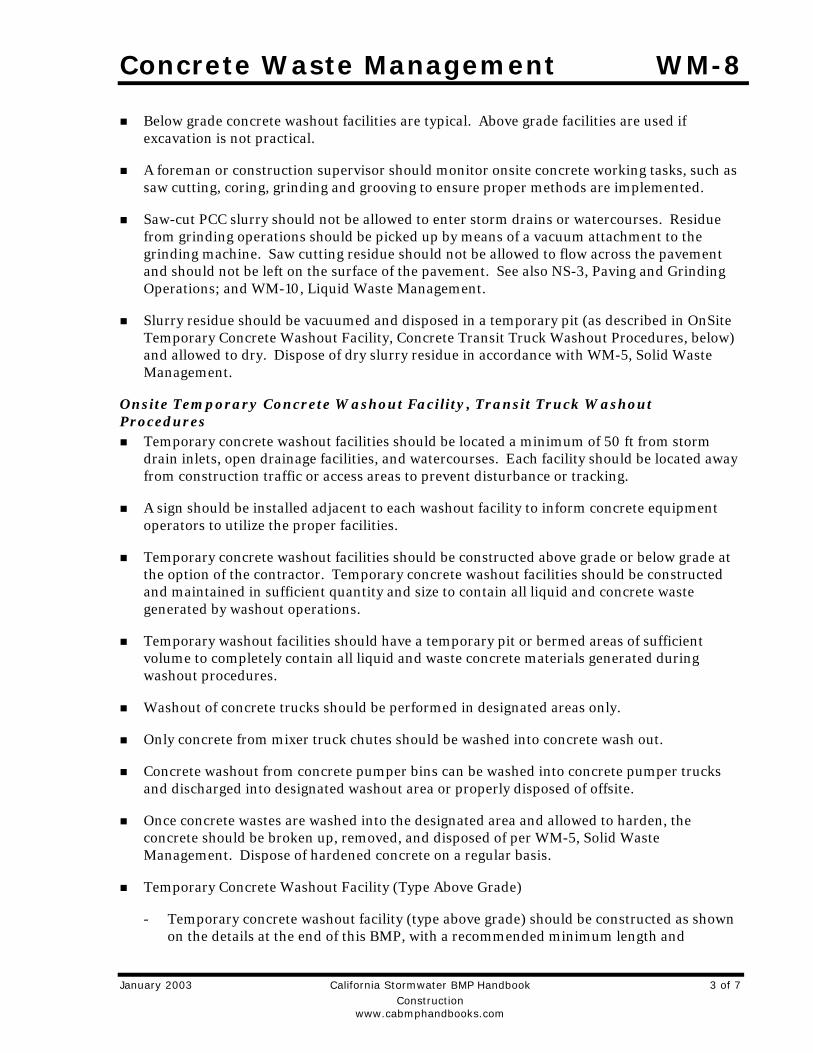
Concrete Waste Management WM-8
January 2003 California Stormwater BMP Handbook 3 of 7 Construction www.cabmphandbooks.com
Below grade concrete washout facilities are typical. Above grade facilities are used if excavation is not practical.
A foreman or construction supervisor should monitor onsite concrete working tasks, such as saw cutting, coring, grinding and grooving to ensure proper methods are implemented.
Saw-cut PCC slurry should not be allowed to enter storm drains or watercourses. Residue from grinding operations should be picked up by means of a vacuum attachment to the grinding machine. Saw cutting residue should not be allowed to flow across the pavement and should not be left on the surface of the pavement. See also NS-3, Paving and Grinding Operations; and WM-10, Liquid Waste Management.
Slurry residue should be vacuumed and disposed in a temporary pit (as described in OnSite Temporary Concrete Washout Facility, Concrete Transit Truck Washout Procedures, below) and allowed to dry. Dispose of dry slurry residue in accordance with WM-5, Solid Waste Management.
Onsite Temporary Concrete Washout Facility, Transit Truck Washout Procedures
Temporary concrete washout facilities should be located a minimum of 50 ft from storm drain inlets, open drainage facilities, and watercourses. Each facility should be located away from construction traffic or access areas to prevent disturbance or tracking.
A sign should be installed adjacent to each washout facility to inform concrete equipment operators to utilize the proper facilities.
Temporary concrete washout facilities should be constructed above grade or below grade at the option of the contractor. Temporary concrete washout facilities should be constructed and maintained in sufficient quantity and size to contain all liquid and concrete waste generated by washout operations.
Temporary washout facilities should have a temporary pit or bermed areas of sufficient volume to completely contain all liquid and waste concrete materials generated during washout procedures.
Washout of concrete trucks should be performed in designated areas only.
Only concrete from mixer truck chutes should be washed into concrete wash out.
Concrete washout from concrete pumper bins can be washed into concrete pumper trucks and discharged into designated washout area or properly disposed of offsite.
Once concrete wastes are washed into the designated area and allowed to harden, the concrete should be broken up, removed, and disposed of per WM-5, Solid Waste Management. Dispose of hardened concrete on a regular basis.
Temporary Concrete Washout Facility (Type Above Grade)
- Temporary concrete washout facility (type above grade) should be constructed as shown on the details at the end of this BMP, with a recommended minimum length and
WM-8 Concrete Waste Management
4 of 7 California Stormwater BMP Handbook January 2003 Construction www.cabmphandbooks.com
minimum width of 10 ft, but with sufficient quantity and volume to contain all liquid and concrete waste generated by washout operations.
- Straw bales, wood stakes, and sandbag materials should conform to the provisions in SE-9, Straw Bale Barrier.
- Plastic lining material should be a minimum of 10 mil in polyethylene sheeting and should be free of holes, tears, or other defects that compromise the impermeability of the material.
Temporary Concrete Washout Facility (Type Below Grade)
- Temporary concrete washout facilities (type below grade) should be constructed as shown on the details at the end of this BMP, with a recommended minimum length and minimum width of 10 ft. The quantity and volume should be sufficient to contain all liquid and concrete waste generated by washout operations.
- Lath and flagging should be commercial type.
- Plastic lining material should be a minimum of 10 mil polyethylene sheeting and should be free of holes, tears, or other defects that compromise the impermeability of the material.
Removal of Temporary Concrete Washout Facilities When temporary concrete washout facilities are no longer required for the work, the
hardened concrete should be removed and disposed of. Materials used to construct temporary concrete washout facilities should be removed from the site of the work and disposed of.
Holes, depressions or other ground disturbance caused by the removal of the temporary concrete washout facilities should be backfilled and repaired.
Costs All of the above are low cost measures.
Inspection and Maintenance Inspect and verify that activity–based BMPs are in place prior to the commencement of
associated activities. While activities associated with the BMP are under way, inspect weekly during the rainy season and of two-week intervals in the non-rainy season to verify continued BMP implementation.
Temporary concrete washout facilities should be maintained to provide adequate holding capacity with a minimum freeboard of 4 in. for above grade facilities and 12 in. for below grade facilities. Maintaining temporary concrete washout facilities should include removing and disposing of hardened concrete and returning the facilities to a functional condition. Hardened concrete materials should be removed and disposed of.
Washout facilities must be cleaned, or new facilities must be constructed and ready for use once the washout is 75% full.

Concrete Waste Management WM-8
January 2003 California Stormwater BMP Handbook 5 of 7 Construction www.cabmphandbooks.com
References Blueprint for a Clean Bay: Best Management Practices to Prevent Stormwater Pollution from Construction Related Activities; Santa Clara Valley Nonpoint Source Pollution Control Program, 1995.
Stormwater Quality Handbooks - Construction Site Best Management Practices (BMPs) Manual, State of California Department of Transportation (Caltrans), November 2000.
Stormwater Management for Construction Activities; Developing Pollution Prevention Plans and Best Management Practice, EPA 832-R-92005; USEPA, April 1992.

WM-8 Concrete Waste Management
6 of 7 California Stormwater BMP Handbook January 2003 Construction www.cabmphandbooks.com
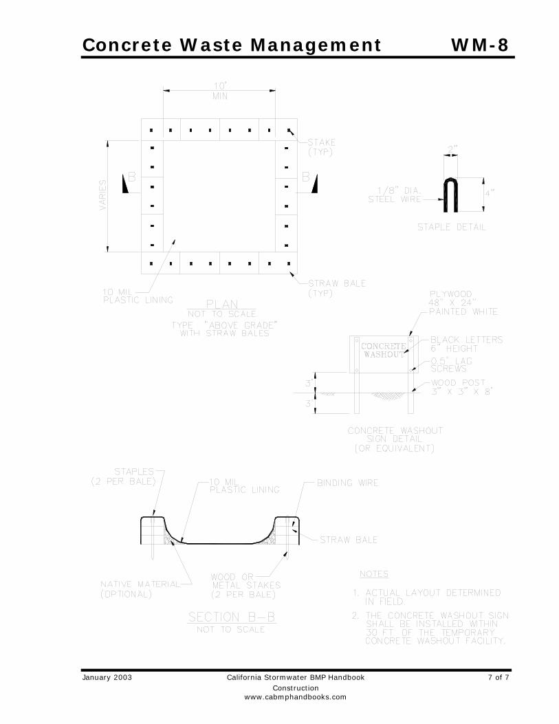
Concrete Waste Management WM-8
January 2003 California Stormwater BMP Handbook 7 of 7 Construction www.cabmphandbooks.com
Sanitary/Septic Waste Management WM-9
January 2003 California Stormwater BMP Handbook 1 of 3 Construction www.cabmphandbooks.com
Description and Purpose Proper sanitary and septic waste management prevent the discharge of pollutants to stormwater from sanitary and septic waste by providing convenient, well-maintained facilities, and arranging for regular service and disposal.
Suitable Applications Sanitary septic waste management practices are suitable for use at all construction sites that use temporary or portable sanitary and septic waste systems.
Limitations None identified.
Implementation Sanitary or septic wastes should be treated or disposed of in accordance with state and local requirements. In many cases, one contract with a local facility supplier will be all that it takes to make sure sanitary wastes are properly disposed.
Storage and Disposal Procedures Temporary sanitary facilities should be located away from
drainage facilities, watercourses, and from traffic circulation. When subjected to high winds or risk of high winds, temporary sanitary facilities should be secured to prevent overturning.
Wastewater should not be discharged or buried within the project site.
Objectives
EC Erosion Control SE Sediment Control TC Tracking Control WE Wind Erosion Control
NS Non-Stormwater Management Control
WM Waste Management and Materials Pollution Control
Legend:
Primary Objective
Secondary Objective
Targeted Constituents
Sediment Nutrients Trash Metals Bacteria Oil and Grease Organics
Potential Alternatives
None
WM-9 Sanitary/Septic Waste Management
2 of 3 California Stormwater BMP Handbook January 2003 Construction www.cabmphandbooks.com
Sanitary and septic systems that discharge directly into sanitary sewer systems, where permissible, should comply with the local health agency, city, county, and sewer district requirements.
Only reputable, licensed sanitary and septic waste haulers should be used.
Sanitary facilities should be located in a convenient location.
Untreated raw wastewater should never be discharged or buried.
Temporary septic systems should treat wastes to appropriate levels before discharging.
If using an onsite disposal system (OSDS), such as a septic system, local health agency requirements must be followed.
Temporary sanitary facilities that discharge to the sanitary sewer system should be properly connected to avoid illicit discharges.
Sanitary and septic facilities should be maintained in good working order by a licensed service.
Regular waste collection by a licensed hauler should be arranged before facilities overflow.
Education Educate employees, subcontractors, and suppliers on sanitary and septic waste storage and
disposal procedures.
Educate employees, subcontractors, and suppliers of potential dangers to humans and the environment from sanitary and septic wastes.
Instruct employees, subcontractors, and suppliers in identification of sanitary and septic waste.
Hold regular meetings to discuss and reinforce disposal procedures (incorporate into regular safety meetings).
Establish a continuing education program to indoctrinate new employees.
Costs All of the above are low cost measures.
Inspection and Maintenance Inspect and verify that activity–based BMPs are in place prior to the commencement of
associated activities. While activities associated with the BMP are under way, inspect weekly during the rainy season and of two-week intervals in the non-rainy season to verify continued BMP implementation.
Arrange for regular waste collection.
If high winds are expected, portable sanitary facilities must be secured with spikes or weighed down to prevent over turning.

Sanitary/Septic Waste Management WM-9
January 2003 California Stormwater BMP Handbook 3 of 3 Construction www.cabmphandbooks.com
References Stormwater Quality Handbooks - Construction Site Best Management Practices (BMPs) Manual, State of California Department of Transportation (Caltrans), November 2000.
Stormwater Management for Construction Activities; Developing Pollution Prevention Plans and Best Management Practice, EPA 832-R-92005; USEPA, April 1992.
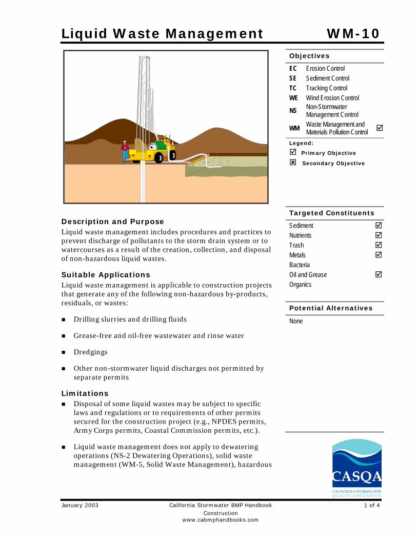
Liquid Waste Management WM-10
January 2003 California Stormwater BMP Handbook 1 of 4 Construction www.cabmphandbooks.com
Description and Purpose Liquid waste management includes procedures and practices to prevent discharge of pollutants to the storm drain system or to watercourses as a result of the creation, collection, and disposal of non-hazardous liquid wastes.
Suitable Applications Liquid waste management is applicable to construction projects that generate any of the following non-hazardous by-products, residuals, or wastes:
Drilling slurries and drilling fluids
Grease-free and oil-free wastewater and rinse water
Dredgings
Other non-stormwater liquid discharges not permitted by separate permits
Limitations Disposal of some liquid wastes may be subject to specific
laws and regulations or to requirements of other permits secured for the construction project (e.g., NPDES permits, Army Corps permits, Coastal Commission permits, etc.).
Liquid waste management does not apply to dewatering operations (NS-2 Dewatering Operations), solid waste management (WM-5, Solid Waste Management), hazardous
Objectives
EC Erosion Control SE Sediment Control TC Tracking Control WE Wind Erosion Control
NS Non-Stormwater Management Control
WM Waste Management and Materials Pollution Control
Legend:
Primary Objective
Secondary Objective
Targeted Constituents
Sediment Nutrients Trash Metals Bacteria Oil and Grease Organics
Potential Alternatives
None
WM-10 Liquid Waste Management
2 of 4 California Stormwater BMP Handbook January 2003 Construction www.cabmphandbooks.com
wastes (WM-6, Hazardous Waste Management), or concrete slurry residue (WM-8, Concrete Waste Management).
Typical permitted non-stormwater discharges can include: water line flushing; landscape irrigation; diverted stream flows; rising ground waters; uncontaminated pumped ground water; discharges from potable water sources; foundation drains; irrigation water; springs; water from crawl space pumps; footing drains; lawn watering; flows from riparian habitats and wetlands; and discharges or flows from emergency fire fighting activities.
Implementation General Practices
Instruct employees and subcontractors how to safely differentiate between non-hazardous liquid waste and potential or known hazardous liquid waste.
Instruct employees, subcontractors, and suppliers that it is unacceptable for any liquid waste to enter any storm drainage device, waterway, or receiving water.
Educate employees and subcontractors on liquid waste generating activities and liquid waste storage and disposal procedures.
Hold regular meetings to discuss and reinforce disposal procedures (incorporate into regular safety meetings).
Verify which non-stormwater discharges are permitted by the statewide NPDES permit; different regions might have different requirements not outlined in this permit.
Apply NS-8, Vehicle and Equipment Cleaning for managing wash water and rinse water from vehicle and equipment cleaning operations.
Containing Liquid Wastes Drilling residue and drilling fluids should not be allowed to enter storm drains and
watercourses and should be disposed of.
If an appropriate location is available, drilling residue and drilling fluids that are exempt under Title 23, CCR § 2511(g) may be dried by infiltration and evaporation in a containment facility constructed in conformance with the provisions concerning the Temporary Concrete Washout Facilities detailed in WM-8, Concrete Waste Management.
Liquid wastes generated as part of an operational procedure, such as water-laden dredged material and drilling mud, should be contained and not allowed to flow into drainage channels or receiving waters prior to treatment.
Liquid wastes should be contained in a controlled area such as a holding pit, sediment basin, roll-off bin, or portable tank.
Containment devices must be structurally sound and leak free.
Containment devices must be of sufficient quantity or volume to completely contain the liquid wastes generated.
Liquid Waste Management WM-10
January 2003 California Stormwater BMP Handbook 3 of 4 Construction www.cabmphandbooks.com
Precautions should be taken to avoid spills or accidental releases of contained liquid wastes. Apply the education measures and spill response procedures outlined in WM-4, Spill Prevention and Control.
Containment areas or devices should not be located where accidental release of the contained liquid can threaten health or safety or discharge to water bodies, channels, or storm drains.
Capturing Liquid Wastes Capture all liquid wastes that have the potential to affect the storm drainage system (such as
wash water and rinse water from cleaning walls or pavement), before they run off a surface.
Do not allow liquid wastes to flow or discharge uncontrolled. Use temporary dikes or berms to intercept flows and direct them to a containment area or device for capture.
Use a sediment trap (SE-3, Sediment Trap) for capturing and treating sediment laden liquid waste or capture in a containment device and allow sediment to settle.
Disposing of Liquid Wastes A typical method to handle liquid waste is to dewater the contained liquid waste, using
procedures such as described in NS-2, Dewatering Operations, and SE-2, Sediment Basin, and dispose of resulting solids per WM-5, Solid Waste Management.
Methods of disposal for some liquid wastes may be prescribed in Water Quality Reports, NPDES permits, Environmental Impact Reports, 401 or 404 permits, and local agency discharge permits, etc. Review the SWPPP to see if disposal methods are identified.
Liquid wastes, such as from dredged material, may require testing and certification whether it is hazardous or not before a disposal method can be determined.
For disposal of hazardous waste, see WM-6, Hazardous Waste Management.
If necessary, further treat liquid wastes prior to disposal. Treatment may include, though is not limited to, sedimentation, filtration, and chemical neutralization.
Costs Prevention costs for liquid waste management are minimal. Costs increase if cleanup or fines are involved.
Inspection and Maintenance Inspect and verify that activity–based BMPs are in place prior to the commencement of
associated activities. While activities associated with the BMP are under way, inspect weekly during the rainy season and of two-week intervals in the non-rainy season to verify continued BMP implementation.
Inspect BMPs subject to non-stormwater discharge daily while non-stormwater discharges occur.
WM-10 Liquid Waste Management
4 of 4 California Stormwater BMP Handbook January 2003 Construction www.cabmphandbooks.com
Remove deposited solids in containment areas and capturing devices as needed and at the completion of the task. Dispose of any solids as described in WM-5, Solid Waste Management.
Inspect containment areas and capturing devices and repair as needed.
References Stormwater Quality Handbooks - Construction Site Best Management Practices (BMPs) Manual, State of California Department of Transportation (Caltrans), November 2000.
Projects/2013/213-0217/SWPPP/11-1-2016
APPENDIX 5
SWRCB GENERAL CONSTRUCTION PERMIT
The State Water Resources Control Board Order No.2009-009-DWQ (NPDES No. CAS 000002) and all attachments hereby included as part of this SWPPP document. Contractor shall download this document at http://www.waterboards.ca.gov

Projects/2013/213-0217/SWPPP/11-1-2016
APPENDIX 6
Work Plans
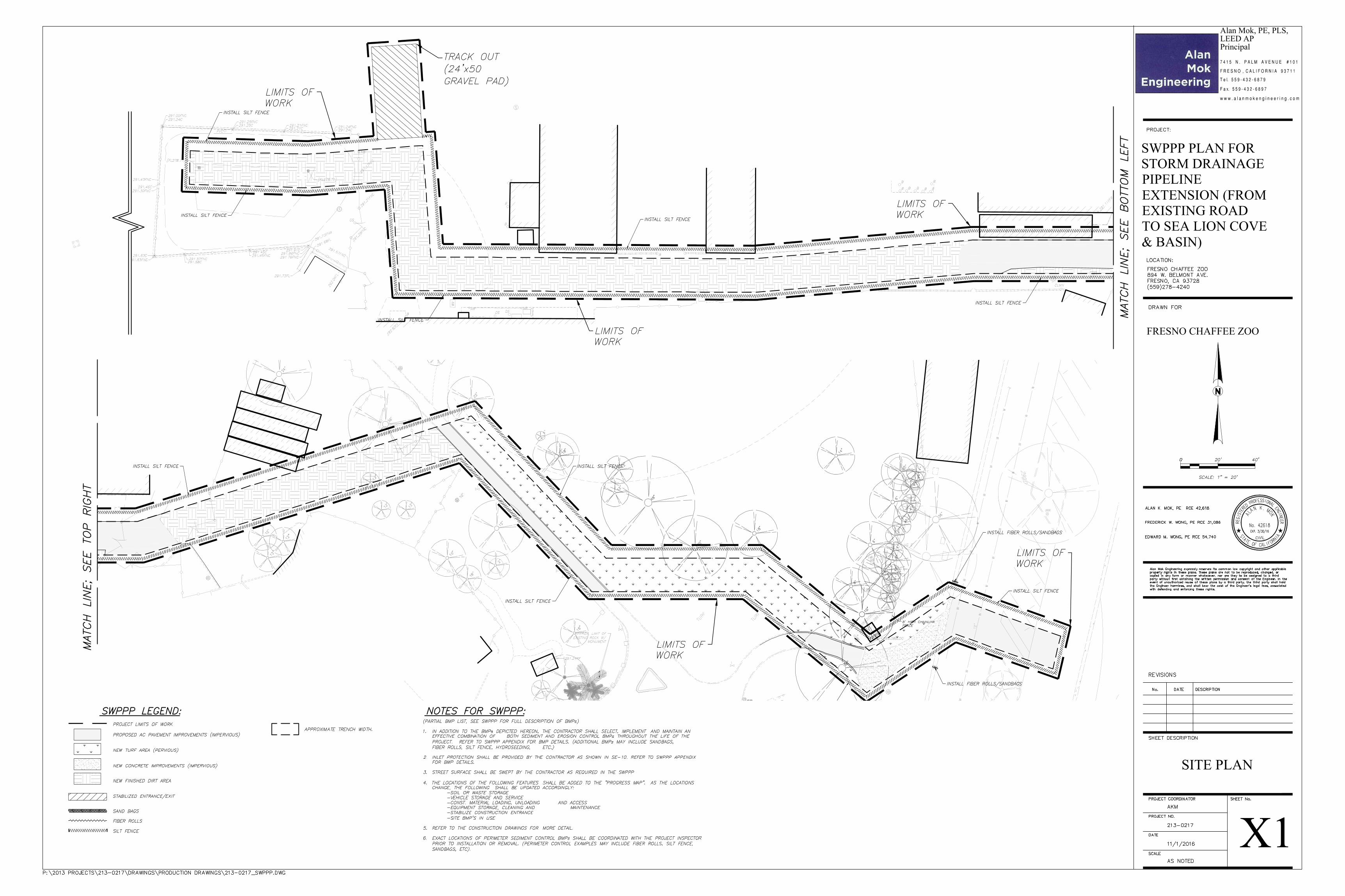
X1
SITE PLAN
w w w . a l a n m o k e n g i n e e r i n g . c o m
7 4 1 5 N . P A L M A V E N U E # 1 0 1
T e l. 5 5 9 - 4 3 2 - 6 8 7 9
F a x. 5 5 9 - 4 3 2 - 6 8 9 7
F R E S N O , C A L I F O R N I A 9 3 7 1 1
Alan Mok, PE, PLS,LEED APPrincipal
FRESNO CHAFFEE ZOO
SWPPP PLAN FORSTORM DRAINAGEPIPELINEEXTENSION (FROMEXISTING ROADTO SEA LION COVE& BASIN)

Projects/2013/213-0217/SWPPP/11-1-2016
APPENDIX 7
Project Schedule
(To Be Inserted By Contractor)

Projects/2013/213-0217/SWPPP/11-1-2016
APPENDIX 8
Employee Training Program

Projects/2013/213-0217/SWPPP/11-1-2016
SITEWORK FOR TRAINING RECORDS
Training Date: Trainer: Topics Covered: Inspections BMP Maintenance/Repair SWPPP Non-Storm Water Discharge BMPs Other(i.e: workshops offered by agencies, SWRCB/RWQCB) Professional organizations
Initial if Received Applicable SWPPP Portions
Name Company Telephone Number
SWPPP Responsibilities*
*SWPPP Responsibilities include one or more of the following: BMP Installation, Inspection, Maintenance; Training; SWPPP Revisions
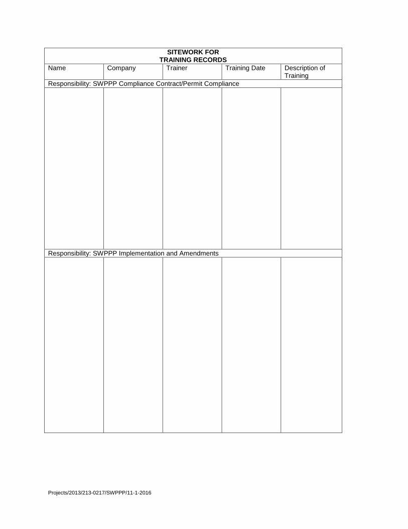
Projects/2013/213-0217/SWPPP/11-1-2016
SITEWORK FOR TRAINING RECORDS
Name Company Trainer Training Date Description of Training
Responsibility: SWPPP Compliance Contract/Permit Compliance
Responsibility: SWPPP Implementation and Amendments

Projects/2013/213-0217/SWPPP/11-1-2016