stiffness heterogeneity of small viral capsids
TRANSCRIPT

HAL Id: hal-03368511https://hal.archives-ouvertes.fr/hal-03368511
Submitted on 7 Oct 2021
HAL is a multi-disciplinary open accessarchive for the deposit and dissemination of sci-entific research documents, whether they are pub-lished or not. The documents may come fromteaching and research institutions in France orabroad, or from public or private research centers.
L’archive ouverte pluridisciplinaire HAL, estdestinée au dépôt et à la diffusion de documentsscientifiques de niveau recherche, publiés ou non,émanant des établissements d’enseignement et derecherche français ou étrangers, des laboratoirespublics ou privés.
Stiffness heterogeneity of small viral capsidsLucas Menou, Yeraldinne Carrasco-Salas, Lauriane Lecoq, Anna Salvetti,
Cendrine Faivre-Moskalenko, Martin Castelnovo
To cite this version:Lucas Menou, Yeraldinne Carrasco-Salas, Lauriane Lecoq, Anna Salvetti, Cendrine Faivre-Moskalenko, et al.. Stiffness heterogeneity of small viral capsids. Physical Review E , AmericanPhysical Society (APS), In press. �hal-03368511�

Stiffness heterogeneity of small viral capsids
Lucas Menou∗,1 Yeraldinne Carrasco Salas∗,1 Lauriane Lecoq,2 Anna
Salvetti,3 Cendrine Faivre Moskalenko,1 and Martin Castelnovo1
1Univ Lyon, Ens de Lyon, CNRS, Laboratoire de Physique, F-69342 Lyon, France2Institut de Biologie et Chimie des Proteines, University of Lyon 1, Lyon, France
3International Center for Research in Infectiology (CIRI),INSERM U111, CNRS UMR 5308, Lyon, France
(Dated: October 7, 2021)
Nanoindentation of viral capsids provides an efficient tool in order to probe their elastic properties.We investigate in the present work the various sources of stiffness heterogeneity as observed in AtomicForce Microscopy (AFM) experiments. By combining experimental results with both numerical andanalytical modeling, we first show that for small viruses a position-dependent stiffness is observed.This effect is strong and has not been properly taken into account previously. Moreover, we show thata geometrical model is able to reproduce this effect quantitatively. Our work suggests alternativeways of measuring stiffness heterogeneities on small viral capsids. This is illustrated on two differentviral capsids: Adeno Associated Virus serotype 8 (AAV8) and Hepatitis B Virus (HBV with T=4).We discuss our results in the light of continuous elasticity modeling.
INTRODUCTION
The elastic properties of viral capsids can be inferredusing nanoindentation experiments. Viral capsids’ sizesranging from tens to hundreds of nanometers, these ex-periments are usually performed with an Atomic ForceMicroscope (AFM), whose operating size range is appro-priate [1]. Capsids of different virus families have beenprobed this way in several works, exhibiting various inter-esting features [2–9]. Depending on the identity of cap-sids and the amplitude of indenting force, one can observeelastic behavior with a linear or non-linear response, plas-tic behavior, and eventually mechanical rupture. Fromthe biological point of view, all these observations are rel-evant since they address the global stability of viruses, aswell as their deformability, which are important physicalinformation to fully understand the various steps of theirreplication cycle.
Most past works dealing with nanoindentation of cap-sids have focused on their linear response. This linearregime allows defining the stiffness effectively as the ra-tio between the force applied and the indentation. Typ-ical stiffness ranges from 0.04 N.m−1 for the Influenzavirus [5, 10] to 3 N.m−1 for the immature particle ofHIV-1 in the presence of envelope glycoproteins for ex-ample [11]. From a structural perspective, viruses arecomposed of mainly nucleic acids packaged inside self-assembled protein shells and eventually a surroundinglipid bilayer or membrane. For most viral capsids, theself-assembly involves multiple copies of identical pro-teins. Yet, the topology of a closed shell imposes thatthe environment at the scale of a single protein is notunique: at exactly twelve locations on the surface of thevirus, proteins belong to a capsomer or face that is pen-tameric (five proteins), while they belong to hexamericcapsomers (six proteins) anywhere else. The precise loca-tion of pentamers determines the global shape of the viralcapsid [12]. It can be either regular with icosahedral sym-metry, irregular and elongated. Focusing on icosahedral
viruses, the three main symmetries (two-fold, three-foldand five-fold) strongly suggest that elastic properties ofcapsids are not uniform [13].
Heterogeneities in stiffness measurements have beenobserved on some viruses, such as the MVM parvovirus[4], or bacteriophages φ29 [2]. In the former case, hetero-geneities have been attributed to the difference in virusorientation during the adhesion on the substrate, offer-ing therefore different capsomer or environments (withtwo-fold, three-fold or fivefold symmetry) on its highestaltitude as probed by the AFM tip. Yet, the effect wasobserved in the presence of viral DNA. Analysis of theAFM images allowed to correlate mechanical propertieswith capsid orientation. In the case of bacteriophages,the difference in stiffness was traced back again to theorientation of the capsid during adhesion, but this wasinterpreted as a signature of the asphericity of the virusrather than inhomogeneity at the single capsomer level.However these observations of stiffness heterogeneity arenot systematic, and for example it is not possible to de-tect significant variations of stiffness for some viruses likeCowpea Chlorotic Mottle Virus (CCMV) depending onits orientation [3]. As a consequence, the presence or ab-sence of stiffness heterogeneity and its origin are far frombeing correctly understood. The purpose of the presentwork is to investigate quantitatively, both experimentallyand theoretically, signatures for these mechanical hetero-geneities.
This paper is organized as follows. In the next section,we present our experimental approach based on AFM-nanoindentation for two different viral capsids, Adeno-Associated Virus 8 (AAV8) and Hepatitis B Virus (HBV,with T=4 capsid conformation), and then the numeri-cal and analytical approach in order to predict and in-terpret the results of indentation experiments quantita-tively. Both approaches are combined and discussed inthe Results section. These findings are then discussedin the light of past literature. Consequences of futureexperiments are also expressed.

2
EXPERIMENTS OF AFM NANOINDENTATIONON VIRAL CAPSIDS
AFM nanoindentation experiments
AAV purificationStock of AAV8 vector particles was produced and pu-
rified on CsCl gradients by calcium phosphate transfec-tion of HEK-293 cells as described previously [14]. Thevector plasmid AAVCMVeGFP, included the enhancedgreen fluorescence cDNA under the control of the cy-tomegalovirus promoter. The total length of the vec-tor was 3769 bases, including the AAV inverted termi-nal repeats. The helper plasmids used for productionwere pDG8 (a kind gift from P. Moullier, INSERM U649,France). After purification and titration by qPCR, theviral stock was kept at −80◦C.
HBV purificationHBV capsids were obtained from the assembly of
Cp183 proteins produced in bacteria following a protocoldetailed in [15]. Cp183 capsids were expressed in E. coliand purified similarly as described previously for trun-cated Cp149. Plasmid of pRSFT7-HBc183opt was trans-formed into E.coli BL21* CodonPlus (DE3) cells andgrown at 37 ◦C in LB medium culture. When OD600reached around 2, expression was induced with 1 mMIPTG overnight at 20 ◦C . Cells were collected by cen-trifugation at 6,000 g for 20 min. For one liter of culture,cells were resuspended in 15 ml of TN300 buffer (50 mMTris, 300 mM NaCl, 2.5 mM EDTA, 5 mM DTT, pH 7.5)and incubated on ice for 45 min with 1 mg/ml of chickenlysozyme, 1X protease inhibitor cocktail solution and 0.5% Triton X-100. 6 µl of benzonase nuclease were addedto digest nucleic acids for 30 min at room temperature.Cells were broken by sonication and centrifuged at 8,000g for 1 h to remove cell debris. The supernatant wasloaded onto a 10 to 60 % sucrose gradient buffered with50 mM Tris pH 7.5, 300 mM NaCl, 5 mM DTT and cen-trifuged in SW-32Ti Beckman Coulter swinging bucketrotor at 140,000 g for 3 h at 4 ◦C. Capsids were iden-tified in gradient fractions by 15 % SDS-Polyacrylamidegel and precipitated by 40 % saturated (NH4)2SO4. Af-ter incubation on ice for 1 h and centrifugation at 20,000g for 1 h, pellets were resuspended in 10ml of purificationbuffer (50 mM Tris pH 7.5, 5 % sucrose, 5 mM DTT, 1mM EDTA). The protein solution was centrifuged againfor 15 min to remove insoluble pellet. The supernatantcontaining soluble capsids was dialyzed overnight againstpurification buffer at 4 ◦C. The purified CP183 capsidsobtained in such an assembly process contain randomshort E Coli nucleic acids [16, 17] .
AFM sample preparation for AAV8 and HBV The viralstock of AAV8 or HBV capsids was diluted to a concen-tration of approximately 6x10⁸ capsids/µl in TN 1mM(Tris 10mM (pH = 7.4) and Nickel(II) chloride (NiCl2)1mM). Immediately after, 5µl of the solution was de-posited onto mica disks previously cleaned using adhesivetape. After 20 minutes of incubation to favor adhesion,
we added 30µl of TN 1mM to the sample and another70µl of TN 1mM in the AFM liquid imaging cell beforeimaging.
AFM imaging and nanoindentation protocol
The samples were imaged using a Bruker NanoscopeV Multimode 8 AFM using PeakForce Mode in liquid.We used three different cantilevers, SNL and ScanAsyst-fluid+ with a nominal tip radius of 2 nm and ScanAsyst-fluid with a nominal tip radius of 20 nm. The SNL andthe two ScanAsyst cantilevers have a nominal spring con-stant of 0.35 and 0.7 N/m, respectively. We use mainlyScanAsyst fluid+cantilevers to compare both AAV8 andHBV nanoindentation and AFM imaging. We used thetwo cantilevers with a tip radius of 2nm (ScanAsystfluid+) and 20nm (ScanAsyst fluid) to study the sizetip effect in the AAV8 particles (supplementary figure2). Also, we studied the effect of the stiffness of the can-tilever in AAV8 nanoindentation; for this, we used theSNL and ScanAsyst fluid + cantilevers ( supplementaryfigure 3). Large scale AFM square images of 3 µm side(512*512 pixels) at 2 Hz scan rate were obtained to verifythe deposition conditions on a large number of capsids.Figure 1 of supplemental material shows a zoom of thoselarge AFM images for AAV8 and HBV capsids.
The capsids were then imaged one by one to performnanoindentation. Images were scanned at 2 Hz over scansegments of 300-500 nm broad. The maximal force var-ied between 200-300 pN . Using Point and Shoot featureof Bruker acquisition software, we defined a line with 15equidistant points over the capsid and 3 points far fromthe capsid to get the surface reference force curve (seeFigure 1A). Additionally, a horizontal height profile thatpasses through the highest point of the capsid is plottedand will be used to determine the capsid radius Rcap,AFMused to normalize the stiffness profile before alignmentand averaging. Nanoindentation data have been analyzedsemi-automatically using a homemade Matlab code. Fig-ure 1B shows the force-displacement F (z) curves sepa-rately according to the indentation position over the vi-ral capsid. The black line is the best curve among thethree recorded over the surface far from the capsid, andits slope represents the cantilever spring constant kc. Allthose curves were aligned with the contact point.
AFM Nanoindentation data analysis We used twomethods to extract the stiffness from the capsid. Inthe first method, we considered the force curve as afunction of the cantilever displacement F (z) that con-tains the deformation of both the cantilever and thecapsid in the first linear regime. Assuming the capsidand the cantilever behave like two springs in series, thecapsid stiffness kcap was calculated using the relationkcap = k(F (z)) = (keffkc)/(keff − kc). The cantileverstiffness kc is determined using the thermal noise method,and the effective stiffness keff is the slope of the linearpart of the F (z) curve. In the second method, kcap is ex-

3
300 nm
2010
Heigh
t(nm)
0
A C
DB
0 2 31-2-3 -1cap,AFMr/R
1.5
k(N
/m)
cap
1.0
0.5
0
20 nm
-10 nm
Height
k(N
/m)
cap
2.0
1.5
1.0
0.5
0
k from F(δ)capk from F(z)cap
k from F(δ) (N=58)capk from F(z) (N=58)cap
z (nm)z (nm)z (nm)20 6 820 4 60 2 4
0.60.50.40.30.20.10
F(nN)
on theborder
on thecentersurface
δ
FIG. 1. Nanoindentation on AAV8 viral particles. (A) Typical image of a AAV8 viral particle deposited on surface.Indentations are performed at different locations represented by colored circles. Three additional indentations, shown by threeblack dots, were made away from the capsid to obtain a reference surface curve that contains only the cantilever deformation.The topographic profile along the black line is also shown. (B) Force-displacement curves for the different locations: (left) greypoints for virus-free locations, (center) green points on the border of viruses, (right) blue points in the center. The black curverepresents an indentation made on the surface and away from the position of the virus (the best of the 3 surface curves recordedaway from the viral capsid. By subtracting at a fixed force the two z-positions on the black curve and a curve obtained withinthe capsid, it is possible to extract the capsid deformation δ. (C) Single particle stiffness extracted at different locations, eitherthrough force-displacement F (z) or force-indentation F (δ) curves. The indentation positions r along the x-axis of the AFMimage have been normalized using the capsid radius Rcap, AFM obtained from the height profile in (A) (D) Ensemble averagedstiffness at different locations (N = 58 viruses). For each lateral position, the symbol (square or losange) is the median of thelocal stiffness distribution, and the bar represents the position of the first and third quartiles for the same distribution.
tracted from the Force indentation F (δ) curve as simplyits slope. To obtain a F (δ) curve, we used the fact thatfor a given applied force F , the indentation δ is found bysubtracting the deformation of the cantilever from the to-tal tip displacement. Figure 1C show the stiffness profileusing both calculation methods. To superimpose N=58differents indented capsid profiles, we aligned them ac-cording to the two lowest points of the profile. Then, theindentation positions r were normalized using the capsidradius Rcap,AFM obtained from the capsid height profile(Fig. 1 A). Finally, we determined a unique stiffness pro-file where the diamond and square represent the medianof all the kcap values for position zero, for example. Theupper and lower error bars are 75 and 25% of the data(see figure 1D).
MODELING AFM NANOINDENTATION ONVIRAL CAPSIDS
Thin shell model for intrinsic stiffness heterogeneity
Thin shell elasticity is very well documented bothin standard textbooks [18–21] and outstanding researchpublications [22–24]. We will mainly recall in this sub-section the main results of interest for our study. In par-
ticular, we present scaling derivations for the stiffness,which have been shown to be appropriate in the regimeof linear elasticity. Within standard 3D elasticity, thedeformation of a material from an unconstrained config-uration is characterized mainly by two tensors: the straintensor which quantifies the relative material deformation,and the stress tensor which quantifies the strength andorientation of forces arising from this deformation. Inthe simplest case of unidimensional material, the linearrelationship between longitudinal strain ε and stress σis called Hooke’s law and it defines the Young modulusas Y = σ/ε, which is an elementary measurement of thestiffness of the material.
The concept of stiffness can be extended to differentmaterial geometry. In the case of thin shells like viralcapsids, it is defined as the ratio between the appliedmechanical force and the indentation length. In the caseof a homogeneous spherical thin shell of width t and ra-dius R, the stiffness results from the balance of in-planestretching/compression and out-of-plane bending. Intro-ducing the 2D stretching modulus as κs = Y t and the 2Dbending modulus (also known as the flexural rigidity) asκb = Y t3/(12(1−σ2)) where σ is the Poisson ratio of thematerial, we define the dimensionless number associatedto stretching/bending balance, which is also known as

4
the Foppl-von Karman number (FvK):
γ =κsR
2
κb(1)
The scaling of stiffness is obtained by estimating the en-ergetic budget associated with small indentation ∆ ofthe spherical shell [18, 25–27]. This indentation modi-fies the curvature of the shell locally over a distance dfrom a value R−1 to ρ−1 ∼ R−1 − 2∆/d2. The bendingcost is of order ∆Eb ∼ κb(ρ
−1 − R−1)2d2 ∼ κb∆2/d2.
The meridians are also compressed by the indentationresulting in a strain ε ∼ ∆/R. The compression costis of order ∆Es ∼ κsε
2d2 ∼ κsd2∆2/R2. The ac-
tual deformation spread d is obtained by minimizingthe sum of bending and compression energies leadingto de ∼ R1/2(κb/κs)
1/4 ∼ Rγ−1/4. The net energyassociated with the indentation is therefore written as∆Etot ∼ k∆2 with the stiffness
k ∼(κsκbR2
)1/2
∼ κsγ−1/2 (2)
This result is strictly valid for small enough indenta-tion, and more importantly for small FvK numbers. In-deed, it has been shown by Lidmar et al. that closedshells with large FvK numbers are strongly faceted withicosahedral symmetry [28]. This phenomenon is relatedto the presence of topological defects, not taken into ac-count in the scaling derivation presented so far. Froma structural point of view, these defects are associatedwith a few numbers of capsomers (local group of pro-teins) having five proteins, while all other capsomers arecomposed of six proteins. This can be understood firstfrom a geometrical point of view: the virus shape and inparticular its icosahedral symmetry can be reproduced bya simple triangulation network model in which each tri-angle represents three proteins, according to the classicalCaspar and Klug approach [29]. Now equilateral trian-gles in a hexagonal phase are known to produce a perfecttiling of a flat plane or any surface having zero curvaturein at least one direction. In contrast, pentagons made ofequilateral triangles form a 3D conical-like structure nat-urally and therefore curve a surface locally in two distinctdirections. This observation can be made more precise byconsidering the distribution of stress within thin shells.The equations describing the mechanical equilibrium ofthin shells are known as the two Foppl-von Karman equa-tions. These highly non-linear coupled equations involvethe out-of-plane deflection w(r) and the in-plane stressσij(r). More precisely, with the introduction of Airystress function χ, which is related to the stress tensorσij by σij = εikεjl∂k∂lχ, where εij is the antisymmetricunit tensor, the second FvK equation reads
∇4χ(r)
κs= s(r)−KG(r) (3)
where s(r) is the defect density and KG(r) is the Gaus-sian curvature [22]. With this equation, it is straight-forward to realize that the morphology of a surface with
non-zero Gaussian curvature is necessarily coupled to thepresence of defects, in order to minimize the elastic stresswithin the shell. In the simplest case, these defects knownas disclinations are the pentamers. Moreover, the num-ber of these defects is fixed by the topology of the sur-face, as it can be seen by Euler relation [30]. For closedshells, this constraint imposes to have exactly twelve pen-tamers. It has been shown by several authors that moststructures obtained using self-assembly will have defectsregularly spaced, giving rise to the icosahedral symmetrypreviously mentioned [31, 32].
As the presence of these defects is obviously relatedto the mechanical properties of the shell, it is expectedthat the stiffness is different at these locations. Severalauthors have analyzed both numerically and experimen-tally the influence of these defects [25, 27, 33–35]. In thelimit of small Fvk numbers, for which the shell shape isspherical, it is possible to extend the previous scaling forthe stiffness estimate by modifying the stretching contri-bution to the energy. Indeed, for a hemispherical cap ofcurvature R−1 and lateral extension d, subjected to van-ishing boundary force σrr(r = d) = 0 [36], the in-planestretching energy yields ∆Es = (π/384)κsd
6/R4 [37–39] . Note that this formula allows recovering previousscaling result for stretching energy as function of inden-tation ∆ by considering hemisphere’s curvature changeR−1 → ρ−1 ∼ R−1− 2∆/d2. In the presence of a centraldisclination of charge s, the stretching energy becomes
∆Es5 = ∆Es +κsd
2
32π
(s2 − πsd2
R2
)(4)
Expanding this energy in ∆ upon curvature change, leadsto correct the stiffness associated with indentation onpentamers (s = π/3) to
k5 ∼ k6 −πκs48
(5)
with k6 ∼ κsγ−1/2. This estimate shows that there is
a slight reduction in stiffness associated with pentamersbut its amplitude is not expected to be significant.
In the opposite limit of large FvK number, the scalingbehavior has been derived by Widom et al. [27]. In thislimit, the viral capsid becomes faceted with icosahedralsymmetry, and indentation experiments are expected togive different results, whether a vertex (i.e. a pentamer)or a face (i.e. a hexamer) of the icosahedron is probed. Inthe latter case, indentation is performed on a flat triangu-lar face. The resulting stiffness in this idealized geometrycan be found in the classical textbook by Timoshenko [21]by solving the first FvK equation for the out-of-plane de-formation profile with appropriate boundary conditions.The result scales like
kface ∼κbR2∼ κsγ−1 (6)
Finally, upon indentation of an icosahedron’s vertex, theforce is mostly transmitted within the plane of each face.This problem has also been considered in the classical

5
textbook by Landau [18]. In this case, the in-plane de-formation induced by a force localized at the edge of aface has been shown to depend in a logarithmic way onthe distance to the edge. The stiffness scales thereforeas:
kvertex ∼κs
lnR/a∼ κs(ln γ)−1 (7)
where a is a small cutoff distance associated with thepresence of the core of the pentamer. The comparison ofthese two stiffnesses kface and kvertex is expected to bemore favorable to experimental discrimination. In partic-ular, the stiffness of pentamers is expected to be larger inthis regime. These results have been derived by Widom etal. using the expected elastic behavior of an icosahedron,so they should be valid for whatever shell structure thatfulfills this symmetry. This is expected to be the casefor large FvK numbers, where the dominant stretchingcost over bending induce such a shape, but it might alsobe valid for very small structures which are intrinsicallyfaceted like T = 1 viral capsid. These structures are sosmall that they are composed of pentamers only, givingrise to a strongly faceted shape.
Numerical simulations of nanoindentation
In order to complement our analytical and experimen-tal approaches, we developed numerical simulations ofthe indentation of thin shells. The elastic properties arereproduced by using the classical model of a triangulatedsurface. Within such a numerical model, in-plane defor-mations are taken into account with bond deformations,varying their lengths, whereas out-of-plane deformationsare taken into account varying dihedral angles betweenadjacent faces or triangles [22]. The elastic energy iswritten as
Eelas =∑〈i,j〉
1
2ks(`〈i,j〉 − `0)2 +
∑α,β
kb(1− cos θα,β), (8)
where `〈i,j〉 is the length of the edge 〈i, j〉. When the lat-ter length is different from the preferred one `0, the bondis stretched or compressed by a spring force proportionalto the spring stiffness ks. Furthermore, kb sets the bend-ing energetic cost for non-zero angle θα,β between the twogiven adjacent faces α, β. Following the works of Seunget al. for example, the relation between stretching andbending modulus in the analytical and numerical modelis given by [22]
ks =
√3
2κs , kb =
2√3κb (9)
In order to mimic as much as possible real viral cap-sids, we analyze the structure of AAV8, which has a Tnumber of 1. Since this small structure might be notlarge enough in terms of a triangular subunit, we divide
each capsomer with a 5×5 subtriangular lattice preserv-ing the icosahedral symmetry and the non-skew capsidshape. For AAV8, we used a radius of R = 12.5nm.
The thin shell interacts both with the flat substrateon which it is lying, and with the approaching sphericalor conical tip. This is realized by adding an adhesionenergy to all vertices Eads =
∑i V (ri). For both interac-
tions, we chose a Morse potential V (r) = V0(1− e−r/a)2,which is naturally repulsive at a very short distance,and attractive at a larger distance. In the limit of verylarge distance, the adhesion force vanishes exponentially.We added a steric cost to each face to prevent the tipfrom entering the triangular network, i.e we also con-sider the repulsion of the barycenter of each face. Con-tact points with the substrate modeled as an infiniterigid flat plate are not allowed to slide tangentially andfixed at their initial position. In our simulation, we setV0 = 2kBT ' 1.2 kcal/mol and a = 2 A. For some sim-ulations, we forbade the motion of bottom vertices, inorder to prevent the shell from rolling.
The relaxation is done using Langevin dynamics:
ri(t+dt) = ri(t)−dt
ζ∇(Eelas+Eads) +
(2kBT
ζdt
)1/2
η,
(10)where ri represents the position of the vertex, η a ran-dom force and ζ the damping coefficient. We chose ζ =1kcal/mol/nm to get good agreement with the experi-mental diffusion time of a capsomer, and the integrationtime-step dt = 400 fs. We assumed quasi-static nanoin-dentation, so that the tip is lowered by 9 pm between eachrelaxation iteration that lasts 2µs. We ensured that anequilibrium state is reached between each tip descent. Fi-nally, since we restricted our investigations on sphericalviruses or weakly faceted viruses for which the FvK num-ber γ ' O(1) or 10, we set ks = 200kBT ' 120kcal/moland kb = 80 kBT ' 50 kcal.mol−1 at ambient tempera-ture T = 298K.
From the simulations, the elastic energy of relaxed con-figurations are obtained, the position of the center of theAFM tip is saved and substracted with its initial posi-tion giving the indentation depth. The maximal inden-tation depth is set to δmax = 0.3R, provided the tip hasnot reached the substrate in the off-centered configura-tions. When coordinates of the tip in the x − y planeare not zeros, the position of the tip is carefully com-puted so that indentations begin at the contact of thenumerical cap. Data are taken between each relaxationstep, and each nanoindentation experiments is repeatedseveral times. A quadratic fit of the form Eelas = k
2 ∆2
using the Nonlinearfit method of Mathematica enablesus to extract the effective stiffness k of the virus for eachexperiment, and error bars are the corresponding rootmean-square deviations resulting from the repetitions.

6
2∆E/(kRγ)
s-1/2
0.15
0.1
0.05
0
-0.05 0.15 0.250.1 0.20.050Δ/R
tip at r=0tip at r=0.48RQuadratic fit ∆E=k ∆eff 2
C
k/(kγ)
seff
-1/2
0.6
0.4
1.0
0.8
0.2
0 1.51 20.50r/(R+R )
D
A
BSpherical tip (R /R=1/5)t
Conical tip (R /R=1/5, α=ϖ/4)t
Model (with a sphere)Model (with a cone)
t
FIG. 2. Simulation of nanoindentation experiments. Snapshots of the indentation process of the triangulated surface by aspherical tip (A) or a conical tip (B). Orange double-arrows shows the area in which the deformation is not negligible. (C)Elastic energy as a function of the relative indentation ∆/R for two positions. Quadratic fit and parameters are also shown.(D) Effective stiffness as a function of the lateral position of the tip for sphere and cone. Simple geometrical model (thin anddashed lines) for effective stiffness. The stiffness is renormalized with classical prediction Eq.2.
Geometrical model for position-dependent stiffness
The scaling results from the previous section assumethat the indentation is performed thanks to a point-likeforce applied precisely on the top of the virus. A realAFM tip has, of course, a finite radius of curvature of or-der few tens of nanometers, and its value is often similarto the radius of curvature of the virus itself. This observa-tion suggests that great care should be the rule while con-sidering the geometry of indentation experiments. An-ticipating any misalignment of the tip with the highestpoint of the virus, we model in this section the variationof stiffness while several lateral positions relative to thetop point of the shell are vertically indented with a finitesize tip. We consider two types of tip: a spherical tip anda conical tip ending with a hemisphere.
The precise geometry considered, and the definition ofthe model parameters, are shown in figure 3. In the caseof a spherical tip, these cartoons illustrate an obvious ef-fect that leads to strong variation of measured stiffnessas the tip goes from the top to the edge of the sphericalshell: upon performing identical vertical indentations atdifferent lateral positions from top to the edge, the corre-sponding shell deformation decreases while approachingthe edge. In the figure, this is highlighted by simplyobserving the intersection of the two spheres. However,real indentation is expected to induce deformation at alarger scale, as it was already discussed in the previous
section. Accordingly, the spreading of the deformation isestimated by de ∼ Rγ−1/4. Nevertheless, the estimationof the overlap region provides a simple way of quantita-tively evaluating the influence of the lateral tip position.In particular, the quantity of interest is the radial inden-tation length ∆r, which represents the maximal radialdeformation along the new rotated axis in direction θ.After a lengthy but straightforward geometrical calcula-tion, one gets for a thin shell of radius R and a sphericaltip of radius Rt:
∆r =1 + ∆
R−∆−√
1 +(
∆R−∆
)2 (1−cos θ2
cos θ2
)1 + ∆
R−∆
(11)
together with the relation between lateral tip position r
and angle cos θ =
√1−
(r
R+Rt
)2
and the new variable
∆ = ∆ cos θ
1+RtR
. In the limit of small indentation, this result
simplifies to ∆r ' ∆
√1−
(r
R+Rt
)2
. A weaker deforma-
tion of the shell in the radial direction is therefore associ-ated with a weaker elastic response (see Fig.3b). Underthe assumption of linear elasticity, the effective stiffnesswhich is position-dependent is written therefore as
k(sphere)eff (r) = k(0)
√1−
(r
R+Rt
)2
(12)

7
r
ΔΔ
θ
α
rΔ
Rt
R
r
δ
Δ Δ
θ
C
D
Δ
Δ
Δ
F
dR
ρ
r
A
B
rΔFIG. 3. Geometrical model for indentation. (A) The shell to be indented has a radius R. Upon vertically indenting on alength ∆, the shell surface deforms horizontally over a typical length 2d. The deformed area is assumed to have a constantcurvature radius ρ. (B) Ideal force-indentation curve in the linear regime. Vertical downward arrow represents the change offorce needed to perform similar vertical indentation at a different lateral position. Horizontal rightward arrow represents thechange in indentation reached at a similar force at a different lateral position. (C) and (D) True deformations (yellow areas)achieved by identical vertical indentation for two different lateral positions, for a spherical tip (C) or conical tip (D)
.
In the case of a conical tip of opening angle α, andterminated with a hemisphere of radius Rt, the radial in-dentation also depends on the position, at least when thespherical part of the tip is in contact with the shell. How-ever, when the conical part is in contact with the shell,the radial indentation associated with a vertical inden-tation ∆ is identical whatever the lateral position. Thisis because one of two principal curvatures of the cone iszero, and therefore the overlap with spherical shell alongthis direction is the same whenever there is a contact.More precisely, the indentation is independent of the po-sition for r > (R+Rt) cosα, i.e. when θ = π/2−α, andits constant value is simply ∆r = ∆ sinα. The stiffnessis therefore
k(cone)eff (r > (R+Rt) cosα) = k(0) sinα (13)
Note that although the radial indentation is constant, itis expected that transverse deformation slightly increaseswith the position as the conical imprint on the shell be-comes larger. The two estimations Eqs. 12 and 13 aresimply based on the geometry of shapes overlapping withthe shell. It can be complemented, for example, by theestimation of the boundary length of the overlap region.This is demonstrated in the appendix. Nevertheless, themajor position-dependent effect is found with the trueindentation length.
The previous estimation assumes that the shell doesnot move laterally upon vertical indentation due tostrong adhesion with the substrate. In the limit of weak
adhesion, the shell is indeed expected to escape the im-posed constraint of indentation by rolling or sliding side-ways. In the intermediate adhesion regime, the shell willbe both deformed and slightly shifted sideways. This ad-ditional shift in the position is expected to lower the trueindentationfurther, and therefore this effect might reducefurther the effective stiffness. The relevance of this effectcan be simply estimated the following way. We assumethat the vertical indentation produces, in addition to thetrue indentation along the symmetry axis of the deforma-tion, a horizontal shift ∆h. The relation between verticalindentation ∆, true indentation ∆r and horizontal shift
is written as ∆r = ∆
√1−
(r+∆h
R+Rt
)2
to the lowest order
in ∆. The equilibrium is maintained by assuming thepresence of a horizontal restoring force |Fadh| = kads∆h,which balances the horizontal contribution of the defor-mation force |Fdeform| = k(0)∆r
r+∆h
R+Rt. To the lowest
order, the horizontal shift is finally estimated as
∆h ' ∆k(0)
kads
r
R+Rt(14)
Therefore the horizontal shift increases with lateral po-sition, and so does the horizontal force associated withadhesion bonds. This estimate shows that adhesion bondrupture might become more likely as the edge of theparticle is approached and that the shell might slip orroll away from the tip. Note that the horizontal shiftdecreases for larger adhesion strength, as it is inversely

8
proportional to kads.
COMPARING THEORY AND EXPERIMENTSOF NANOINDENTATION OF VIRAL CAPSIDS
Geometrical stiffness heterogeneity
According to the protocol described in the previousexperimental sections, we performed nanoindentation ex-periments with AFM on two different viral capsids, AAV8and HBV (T=4 capsids) (Fig.1). For each viral particleto be investigated, we recorded force-displacement curvesat different lateral positions across the particle (Fig.1A).The resulting curves for one particular, but representa-tive capsid, is shown in figure 1B, in which all the curveshave been horizontally aligned such that force raises atthe same vanishing displacement.
These curves show clearly that the elastic response isstrongly dependent on the lateral position of the tip withrespect to the top of the particle. Using the averagebest force-displacement curve recorded for the substrate,one can obtain a similar picture on the force-indentationcurves (Fig.1C). We recall here that the indentation δ isthe net deformation of the shell with respect to its initialconfiguration prior to tip-shell contact. Both types ofcurve exhibit some oscillations when vertical indentationis performed far from the top of the shell (Fig.1B). Thisis likely to be associated with a partial loss of substrateadhesion: as it was discussed in the analytical model,vertical indentation performed at large distance from thetop of the shell induces a weak deformation of the shell,but also exerts an increasing horizontal force on the ad-hesion bonds between the capsid and the substrate.
Assuming a linear elastic response, the force curves canbe used to estimate the stiffness, as it is shown in figure1C, where this information is represented as a function oflateral position for a single particle. This demonstratesvery clearly that the effective stiffness decreases as theindentation experiment is performed on even not so dis-tant lateral positions from the capsid’s top. This ob-servation survives when the results on several particlesare aggregated (Fig.1D). Notice though that due to theoscillations in the force-displacement curves for large lat-eral positions, the effective stiffness in these regions hasa larger uncertainty. We also performed similar indenta-tion measurements on HBV (T=4 viral capsids). In thiscase, we observed position-dependent stiffness, althoughwith a weaker amplitude, as will be discussed later.
In order to investigate more quantitatively thisposition-dependent stiffness and its dependence on var-ious parameters of the system, we used the moleculardynamics simulations described in the previous model-ing sections. The indentation process is reproduced bycomputing the change in elastic energy of a triangulatedsurface constrained by the presence of a spherical or con-ical tip (fig.2A and B) and a flat substrate.
Fitting the expected quadratic dependence of elastic
energy under the assumption of linear elasticity, we ex-tract the stiffness for different lateral positions (fig.2C).The resulting stiffness variation, shown in figure 2D, issimilar to the observed experimental stiffness change.Using numerical simulations also allows to investigatethe influence of various parameters on the position-dependent stiffness such as tip geometry (spherical orconical) and elastic parameters.
Comparing both experimental and numerical indenta-tions, we observed first a strong variation of the stiff-ness. This effect can be qualitatively understood by asimple geometrical model previously mentioned: a ver-tical indentation performed at different lateral positionswill correspond to weaker effective deformation of theshell, resulting in a weaker restoring force. From a quan-titative point of view, this geometrical model provides asimple prediction that can be compared to both exper-iments and simulations. In the case of a spherical tip,the expected stiffness decreases toward vanishing value,and the simulations confirm this prediction. On the con-trary for a conical tip, the stiffness should first decreasesimilarly to the spherical case, and then reach a non-zeroconstant value. Again, this is also observed both in theexperiments and in the simulations. However, the lattercurves show a stronger decrease in the stiffness comparedto the simple geometrical model, suggesting the presenceof other effects at play in the real system.
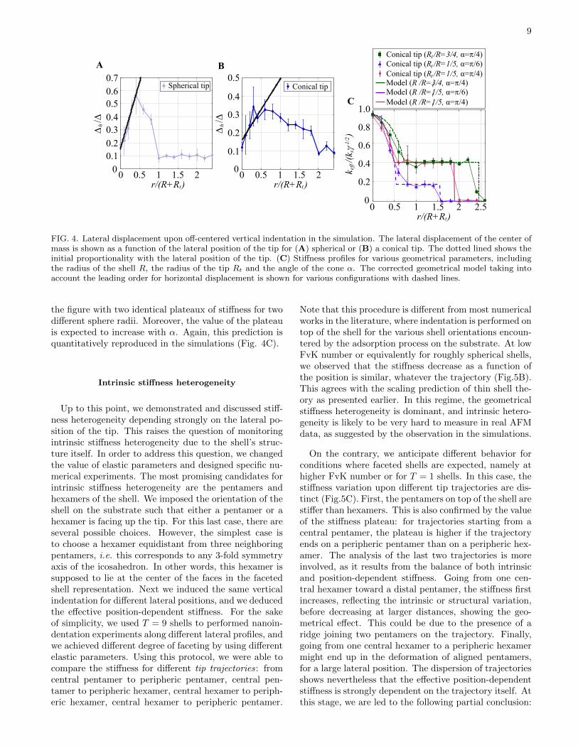
The first major correction that can be brought tothe geometrical model is to consider horizontal displace-ment which is concomitant with the vertical indenta-tion. Within the simulations, we can indeed computefor each lateral position of the tip, the net horizontalshift of the shell center of mass as compared to the orig-inal position prior to indentation. This is shown in fig-ure Fig4 A and B, respectively for spherical and coni-cal tip. It is observed within these plots that the hori-zontal shift increases first linearly with the lateral posi-tion, in qualitative agreement with scaling model pre-diction Eq.14. This horizontal shift could be associ-ated with partial loss of adhesion sites between the shelland substrate or with a more global deformation of theshell. Plugging a linear horizontal displacement ∆h = Arin the original geometrical model introduces a rescalingcorrection to the geometrical model Eq.12 in the form
k(sp)eff = k(0)
√1− (r/(R+Rt))2(1 +A)2. This predicts
indeed a stronger decrease of stiffness as compared tothe original geometrical model. This argument can alsobe applied to the conical model. Using A as an ad-justable parameter, the corrected geometrical shows abetter agreement with experimental (supplementary fig-ure 2) and simulated data (Fig. 4C).
Simulations were also used to address the influence ofvarious parameters on the effective stiffness measured.This is shown in figure 4C, for example. The geometricalmodel predicts that the value of constant stiffness forthe conical tip does depend only on the opening angleof the cone (see Eq. 13) but not on the value of sphereradius terminating the cone. This behavior is observed in
9
1.51 20.50 1.51 20.50r/(R+R )t r/(R+R )t
1.51 2 2.50.50r/(R+R )t
∆/∆h 0.3
0.2
0.50.4
0.70.6
0.10
∆/∆h
0.3
0.2
0.5
0.4
0.1
0
Spherical tip Conical tip
A B
C
k/(kγ)
seff
-1/2
0.6
0.4
1.0
0.8
0.2
0
Conical tip (R /R=1/5, α=ϖ/6)tConical tip (R /R=1/5, α=ϖ/4)t
Conical tip (R /R=3/4, α=ϖ/4)t
Model (R /R=1/5, α=ϖ/6)tModel (R /R=1/5, α=ϖ/4)t
Model (R /R=3/4, α=ϖ/4)t
FIG. 4. Lateral displacement upon off-centered vertical indentation in the simulation. The lateral displacement of the center ofmass is shown as a function of the lateral position of the tip for (A) spherical or (B) a conical tip. The dotted lined shows theinitial proportionality with the lateral position of the tip. (C) Stiffness profiles for various geometrical parameters, includingthe radius of the shell R, the radius of the tip Rt and the angle of the cone α. The corrected geometrical model taking intoaccount the leading order for horizontal displacement is shown for various configurations with dashed lines.
the figure with two identical plateaux of stiffness for twodifferent sphere radii. Moreover, the value of the plateauis expected to increase with α. Again, this prediction isquantitatively reproduced in the simulations (Fig. 4C).
Intrinsic stiffness heterogeneity
Up to this point, we demonstrated and discussed stiff-ness heterogeneity depending strongly on the lateral po-sition of the tip. This raises the question of monitoringintrinsic stiffness heterogeneity due to the shell’s struc-ture itself. In order to address this question, we changedthe value of elastic parameters and designed specific nu-merical experiments. The most promising candidates forintrinsic stiffness heterogeneity are the pentamers andhexamers of the shell. We imposed the orientation of theshell on the substrate such that either a pentamer or ahexamer is facing up the tip. For this last case, there areseveral possible choices. However, the simplest case isto choose a hexamer equidistant from three neighboringpentamers, i.e. this corresponds to any 3-fold symmetryaxis of the icosahedron. In other words, this hexamer issupposed to lie at the center of the faces in the facetedshell representation. Next we induced the same verticalindentation for different lateral positions, and we deducedthe effective position-dependent stiffness. For the sakeof simplicity, we used T = 9 shells to performed nanoin-dentation experiments along different lateral profiles, andwe achieved different degree of faceting by using differentelastic parameters. Using this protocol, we were able tocompare the stiffness for different tip trajectories: fromcentral pentamer to peripheric pentamer, central pen-tamer to peripheric hexamer, central hexamer to periph-eric hexamer, central hexamer to peripheric pentamer.
Note that this procedure is different from most numericalworks in the literature, where indentation is performed ontop of the shell for the various shell orientations encoun-tered by the adsorption process on the substrate. At lowFvK number or equivalently for roughly spherical shells,we observed that the stiffness decrease as a function ofthe position is similar, whatever the trajectory (Fig.5B).This agrees with the scaling prediction of thin shell the-ory as presented earlier. In this regime, the geometricalstiffness heterogeneity is dominant, and intrinsic hetero-geneity is likely to be very hard to measure in real AFMdata, as suggested by the observation in the simulations.
On the contrary, we anticipate different behavior forconditions where faceted shells are expected, namely athigher FvK number or for T = 1 shells. In this case, thestiffness variation upon different tip trajectories are dis-tinct (Fig.5C). First, the pentamers on top of the shell arestiffer than hexamers. This is also confirmed by the valueof the stiffness plateau: for trajectories starting from acentral pentamer, the plateau is higher if the trajectoryends on a peripheric pentamer than on a peripheric hex-amer. The analysis of the last two trajectories is moreinvolved, as it results from the balance of both intrinsicand position-dependent stiffness. Going from one cen-tral hexamer toward a distal pentamer, the stiffness firstincreases, reflecting the intrinsic or structural variation,before decreasing at larger distances, showing the geo-metrical effect. This could be due to the presence of aridge joining two pentamers on the trajectory. Finally,going from one central hexamer to a peripheric hexamermight end up in the deformation of aligned pentamers,for a large lateral position. The dispersion of trajectoriesshows nevertheless that the effective position-dependentstiffness is strongly dependent on the trajectory itself. Atthis stage, we are led to the following partial conclusion:

10
6
5
5
5
6
5 6
6
5
5
A
1.51 20.50r/(R+R )t
k/(kγ)
seff
-1/2
0.6
0.4
0.2
0
66
55
65566 6
6 5 5 65 5
C Faceted shell
1.51 20.50r/(R+R )t
B
k/(kγ)
seff
-1/2 0.6
0.4
0.2
0
56
5 6
6 66 5 5 6
5 5
Spherical shell
FIG. 5. Heterogeneity of stiffness profiles in the simulation. The profiles corresponding to particular paths along the shell’ssurface are shown in (A) as colored dashed lines on faceted or spherical shells. The stiffness values associated with the profilesare shown for faceted shells with γ ' 576.5 (B) or spherical shell with γ ' 57.65 (C). The underlying connectivity of the shellwas kept constant and correspond formally to the T = 9 icosahedral shell. Four trajectories have been considered in bothcases: pentamer to pentamer (bright maroon), pentamer to hexamer (dark maroon), hexamer to hexamer (blue) and hexamerto pentamer (red). Profiles are similar for spherical shells, while they show some heterogeneity for faceted shells.
a closed shell that has a roughly spherical shape doesnot exhibit significant intrinsic stiffness heterogeneity, asall stiffness profiles superimpose. Therefore the presenceof pentamers and hexamers does not lead necessarily tostiffness heterogeneity. On the contrary, when the shellexhibits significant faceting, stiffness heterogeneity is ob-served, and different trajectories lead to different stiffnessprofiles.
Next, we tried to observe similar heterogeneity signa-tures in the experiments on both viral capsids AAV8(T = 1) and HBV (T = 4) using several indentationsperformed at various lateral positions. First, we com-pared the average trajectory stiffness vs position alongAAV8 and HBV capsids measured for several viral par-ticles (Fig.6B). For both capsids, the general trend is adecrease of stiffness from the center to the edge of theparticle, in agreement with the analytical and numericalmodel. It is possible to rescale the stiffness with the topvalue and the position with the appropriate size R+Rt,so that both profiles collapse onto a single curve, up tothe experimental error (Fig. 6C). This is consistent withthe geometrical modeling proposed so far. The medianstiffness value on the top, 0.8N/m for AAV8 and 0.3N/mfor HBV, is also consistent with other values from theliterature [8, 40, 41]. Interestingly, we observed that thetrajectories are relatively spread around the average tra-jectory, the effect being larger for AAV8 than HBV cap-sids, as can be noticed from the values of the first andthird quartile of the local stiffness distribution. In orderto relate these results with the ones obtained in the simu-lation (fig.5B), we extracted first the stiffness distributionon the top of the viruses for AAV8 and HBV (fig.7A and7B). These distributions show multimodal features. It ispossible to use these modes of top stiffness distributionto select subpopulations of profile (fig.7C and 7D). Inpractice, this is performed by inspecting the cumulativetop stiffness distribution, which shows several significantslope ruptures see supplementary figure 4. These sub-
population profiles are clearly distinguishable, and theystrongly suggest the presence of stiffness inhomogeneity.Now, within the simulations, the exact orientation of theadsorbed particles is known, and therefore it is likely thatthe observed subpopulations of profiles in the experimentare representative of the very same feature: the differ-ence in orientation of adsorbed viral particles generatesdifferent stiffness profiles. Using subpopulation profiles,we recover the observations made in figure 6B: relativeinhomogeneity is stronger for AAV8 than for HBV cap-sids. Moreover, since the simulation suggests that het-erogeneous stiffness profiles correlate to a faceted shape,we confirm from our mechanical experiment that stiffnessheterogeneity of AAV8 viral capsids is associated with amore faceted shape than HBV viral capsid. This con-clusion is in agreement with the structural informationon these viral capsids, as AAV8 is a T=1 shell (stronglyfaceted), and HBV is a T=4 shell (weakly faceted, morespherical) [40, 42, 43].
CONCLUSION
In the present work, we investigated the sources of stiff-ness heterogeneities that can arise in indentation exper-iments of nano-sized shells like viral capsids. We firstidentified and rationalized a purely geometrical effectthat reduces the stiffness of the shell as the vertical in-dentation axis is shifted towards the border of the shell.This is due to the decrease of the net deformation foridentical vertical indentation. When compared to sim-ulations, the prediction of a geometrical model that weproposed shows additionally that the adhesion proper-ties of the shell to the substrate are rather importantto account quantitatively for the observations. To ourknowledge, this geometric effect has been already ob-served on influenza virus[44], but this is the first timethat it has been quantitatively investigated. It has some

11
BA
1.50.50 1cap,AFMr/R
1.50.50 1cap,AFMr/R
k/k
(r=0)
cap
cap
2
1
1.5
0.5
0
C
k(N/m)
cap
1.5
0.5
1
0
AAV8 (N=58)HBV (N=42)AAV8 (N=58)HBV (N=42)
AAV8 (N=58)HBV (N=42)AAV8 (N=58)HBV (N=42)
AAV8 (T=1)
HBV (T=4)
FIG. 6. Comparison between AAV8 and HBV average stiffness profiles. (A) Expected geometrical shape for AAV8 and HBV,based on their T-numbers. (B) Ensemble averaged stiffness profiles as function of lateral positions for AAV8 (blue curve) andHBV (grey curve). For each position, the empty circle and extremities of the bar are respectively the median, the first and thirdquartile of the local stiffness distribution. (C) Rescaling of the two average profiles by their respective maximal amplitude,showing similar profiles
0.04
00 21.51.5 1
0.02AAV8(T=1)
AAV8 (T=1)
A
1.50.50 1
k(N/m)
cap
1.5
1.0
0.5
0
C
cap,AFMr/R
D
0.5
0.30.4
0.20.10
1.50.50 1cap,AFMr/R
Probabilitydensity
k (N/m)cap
0.03
0.01
0.02
00 0.6 0.80.40.2
HBV(T=4)
HBV (T=4)
B
(N=15) (N=25) (N=15) (N=23 (N=11) (N=4)
FIG. 7. Heterogeneity of stiffness profiles in the experiments. Stiffness distribution on the top of AAV8 (A) and HBV (B) viralcapsids. Different subpopulations (identified by different colors) have been identified using slope ruptures in the cumulativetop stiffness distributions for each curve. (C) Subpopulations of AAV8 stiffness profile with similar colors as in (A). (D)Subpopulations of HBV stiffness profile with similar colors as in (B).
important consequences in the interpretation of nanoin-dentation experiments, as the stiffness value might beunder-estimated in the case of measurements with poorpositioning precision.
The recognition of this geometrical effect allowed usto define a new procedure to highlight intrinsic stiff-ness heterogeneity coming from the structural and elasticproperties of the shell, and not from the relative geom-etry between the tip and the shell. Within this proce-dure, heterogeneity is evidenced by comparing stiffnesstrajectories obtained by performing several indentationexperiments while scanning the investigated shell. Us-ing simulations, we showed that if the shell is ratherspherical, all trajectories collapse onto the expected geo-metrical profile. On the contrary, for a faceted shell re-sembling an icosahedron, stiffness trajectories are ratherdispersed, reflecting intrinsic stiffness heterogeneity. Wemeasured this effect experimentally for two examples ofsmall viruses, namely AAV8 and HBV (T=4). The dif-
ferent degree of intrinsic stiffness heterogeneity found forthese viruses are consistent with their structure: AAV8is a T=1 shell, with strong faceting, while HBV capsid isa T=4 with weaker faceting (more spherical shape); ac-cordingly, the dispersion of stiffness profiles is larger forAAV8 than for HBV.
We acknowledge useful discussions at various stages ofthis work with Guillaume Tresset, Arezki Boudaoud andCatherine Quilliet. Part of this work has been fundedthrough a CNRS ”PEPS” grant entitled Modeling viralinfections in 2018. Y.C.-S. acknowledges the financialsupport of the National Agency for Research and Devel-opment (ANID) / Scholarship Program / DOCTORADOBECAS CHILE 72170177. LL. acknowledges the finan-cial support from the CNRS (CNRS-Momentum 2018).

12
[1] R. Zandi, B. Dragnea, A. Travesset, and R. Podgornik.On virus growth and form. Phys. Rep., in press, 2020.
[2] I.L. Ivanovska, P.J. de Pablo, B. Ibarra, G. Sgalari,F.C. MacKintosh, J.L. Carrascosa, C.F. Schmidt, andG.J. Wuite. Bacteriophage capsids: tough nanoshellswith complex elastic properties. Proc. Nat. Acad. Sci.,101:7600, 2004.
[3] J.P. Michel, I.L. Ivanovska, M.M. Gibbons, W.S. klug,C.M. Knobler, G.J. Wuite, and C.F. Schmidt. Nanoin-dentation studies of full length and empty viral capsidsand the effects of capsid protein mutations on elasticityand strength. Proc. Nat. Acad. Sci., 103:6184, 2006.
[4] C. Carrasco, A. Acrreira, I.A. Schaap, P.A. Serena,J. Gomez-Herrero, M.G. Mateu, and P.J. de Pablo. Dna-mediated anisotropic mechanical reinforcement of a virus.Proc. Nat. Acad. Sci., 103:13706, 2006.
[5] M.G. Mateu. Mechanical properties of viruses analyzedby atomic force microscopy: a virological perspective.Vir. Research, 168:1, 2012.
[6] M.G. Mateu. Assembly, stability and dynamics of viruscapsids. Arch. Biochem. Biophys., 531:65, 2013.
[7] C. Zeng, M. Hernando-Perez, B. Dragnea, X. Ma,P. van der Schoot, and R. Zandi. Contact mechanics ofa small icosahedral virus. Phys. Rev. Lett., 119:038102,2017.
[8] C. Zeng, S. Moller-Tank, A. Asokan, and B. Drag-nea. Probing the link among genomic cargo, contactmechanics, and nanoindentation in recombinant adeno-associated virus 2. J. Phys. Chem B, 121:1843, 2017.
[9] N. Martin-Gonzalez, P. Ibanez-Freire, A. Ortega-Esteban, M. Laguna-Castro, C. San Martin, A. Val-buena, R. Delgado-Buscalioni, and P.J. de Pablo. Long-range cooperative disassembly and aging during aden-ovirus uncoating. Phys. Rev. X, 11:021025, 2021.
[10] F. Eghiaian, I.A. Schaap, A. des Georges, J.J. Skehel,and C. Veigel. The influenza virus mechanical propertiesare dominated by its lipid envelope. Biophys. J., 96:15,2009.
[11] N. Kol, Y. Shi, M. Tsvitov, D. Barlam, R.Z. Shneck,M.S. Kay, and I. Rousso. A stiffness switch in humanimmunodeficiency virus. Biophys. J., 92:1777, 2007.
[12] M. Castelnovo. Viral self-assembly pathway and mechan-ical stress relaxation. Phys. Rev. E, 95:052405, 2017.
[13] M. Aznar, A. Luque, and D. Reguera. Relevance of cap-sid structure in the bucklingand maturationof sphericalviruses. Phys. Biol., 9:036003, 2012.
[14] A. Salvetti, S. Oreve, G. Chadeuf, D. Favre, Y. Cherel,P. Champion-Arnaud, J. David-Ameline, and P. Moul-lier. Factors influencing recombinant adeno-associatedvirus production. Hum. Gene Ther., 9:695, 1998.
[15] L. Lecoq, S. Wang, T. Wiegand, S. Bressanelli, M. Nas-sal, B. Meier, and A. Bockmann. Solid statement [13c-15n] nmr resonance assignment of hepatitis b virus coreprotein. Biomolecular NMR Assignments, 12:205, 2018.
[16] J. Z. Porterfield, M.S. Dhason, D.D. Loeb, M. Nassal,S.J. Stray, and A. Zlotnick. Full-length hepatitis b viruscore protein packages viral and heterologous rna withsimilarly high levels of cooperativity. J. Virol., 84:7174,2010.
[17] J. Heger-Stevic, P; Zimmermann, L. Lecoq, B. Bottcher,and M. Nassal. Hepatitis b virus core protein phosphory-lation: identification of the srpk1 target sites and impactof their occupancy on rna binding and capsid structure.
Plos. Pathogens, 14:e1007488, 2018.[18] L.D. Landau and E.M. Lifshitz. Theory of elasticity.
Pergamon press, 1970.[19] E. Ventsel and T. Krauthammer. Thin plates and shells:
theory, analysis and applications. CRC press, 2001.[20] C.R. Calladine. Theory of shell structures. Cambridge
University Press, 2010.[21] S. Timoshenko and S. Woinowsky-Krieger. Theory of
plates and shells. McGraw-Hill India (2nd Ed.), 2010.[22] H. S Seung and D. R Nelson. Defects in flexible mem-
branes with crystalline order. Phys. Rev. A, 38:1005,1988.
[23] M. Bowick, D.R. Nelson, and A. Travesset. Interactingtopological defects on frozen topographies. Phys. Rev. B,62:8738, 2000.
[24] A. Travesset. Ground state of a large number of particleson a frozen topography. Phys. Rev. E, 72:036110, 2005.
[25] M. Buenemann and P. Lenz. Elastic properties and me-chanical stability of chiral and filled capsids. Phys. Rev.E, 78:051924, 2008.
[26] S. Komura, K. Tamura, and T. Kato. Buckling of spher-ical shells adhering onto a rigid substrate. Eur. Phys. J.E, 18:343, 2005.
[27] M. Widom, J. Lidmar, and D.R. Nelson. Soft modes nearthe buckling transition of icosahedral shells. Phys. Rev.E, 76:031911, 2007.
[28] J. Lidmar, L. Mirny, and D.R. Nelson. Virus shapes andbuckling transitions in spherical shells. Phys. Rev. E,68:051910, 2003.
[29] D.L. Caspar and A. Klug. Physical principles in the con-struction of regular viruses. Cold Spring Harbor Symp.Quant. Biol., 27:1, 1962.
[30] L. Giomi and M. Bowick. Crystalline order on riemannianmanifolds with variable gaussian curvature and bound-ary. Phys. Rev. B, 76:054106, 2007.
[31] S. Li, P. Roy, A. Travesset, and R. Zandi. Why largeicoshedral viruses need scaffolding proteins. Proc. Nat.Acad. Sci., 115:10971, 2018.
[32] L. Menou and M. Castelnovo. Mechanical stress relax-ation in molecular self-assembly. Soft Matter, 15:6180,2019.
[33] M. Gibbons and W. Klug. Influence of non uniform ge-ometryon nanoindentation of viral capsids. Biophys. J.,95:3640, 2008.
[34] W. S. Klug, W. H. Roos, and G. J. L. Wuite. Unlockinginternal prestress from protein nanoshells. Phys. Rev.Lett., 109:168104, 2012.
[35] A. Llauro, B. Schwartz, R. Koliyatt, P. de Pablo, andT. Douglas. Tuning viral capsid nanoparticle stabilitywith symmetrical morphogenesis. ACS Nano, 10:8465,2016.
[36] This approximation has been made for the sake of sim-plicity. We checked that the scaling results are not alteredwhen non-zero boundary force σb is taken into account.
[37] S. Schneider and G. Gompper. Shapes of crystalline do-mains on spherical fluid vesicles. Eur. Phys. Lett., 70:136,2005.
[38] G. M. Grason. Defects in crystalline packings of twistedfilament bundles. i. continuum theory of disclinations.Phys. Rev. E, 85:031603, 2012.
[39] A. Azadi and G. M. Grason. Defects in crystalline pack-ings of twisted filament bundles. ii. dislocations and grainboundaries. Phys. Rev. E, 85:031604, 2012.
[40] W. H. Roos, M. M. Gibbons, A. Arkhipov, C. Uetrecht,N. R. Watts, P. T. Wingfield, A. C. Steven, A. J. R. Heck,K. Schulten, W. S. Klug, and G. J. L. Wuite. Squeezing

13
protein shells: how continuum elastic models, moleculardynamics simulations, and experiments coalesce at thenanoscale. Biophys. J., 99:1175, 2010.
[41] C. Uetrecht, C. Verluis, N.R. Watts, W.H. Roos, G.J.L.Wuite, P.T. Wingfield, A.C. Steven, and A.J.R. Heck.High resolution spectroscopy of viral assemblies: molec-ular composition and stability of dimorphic hepatatis bvirus capsids. Proc. Nat. Acad. Sci., 105:9216, 2008.
[42] S. A. Wynne, R. A. Crowther, and A. G. W. Leslie. The
crystal structure of the human hepatitis b virus capsid.Mol. Cell, 3:771, 1999.
[43] X. Yu, L. Jin, J. Jih, C. Shih, and Z. H. Zhou. 3.5angstroms cryoem structure of hepatitis b virus coreassembled from full-length core protein. PLoS One,8:e69729, 2013.
[44] S. Li, F. Eghiaian, C. Sieben, A. Herrmann, and I.A.T.Schaap. Bending and puncturing the inlufenza lipid en-veloppe. Biophys. J., 100:637, 2011.