stereotactic treatment definitions and literature overview
TRANSCRIPT

<DPF, NSUH-LIJ > 1
STEREOTACTIC TREATMENTDEFINITIONS AND LITERATURE
OVERVIEW
Doracy P. Fontenla, Ph.D.Associate Professor_AECOM
Associate Chief PhysicistNSUH-LIJ Health Systems

<DPF, NSUH-LIJ > 2
Radiosurgery Definitions
Stereotactic/ Stereotaxy : Clinical procedurebased on reference markers to precisely locatea target within 3D-boundaries.
Combine the use of a stereotatic apparatus &radiation beams
Two modalities:Stereotactic Radiosurgery - SRS
orStereotactic Radiotherapy - SRT

<DPF, NSUH-LIJ > 3
STEREOTACTIC RADIOSURGERY (SRS)
A “non-invasive” techniqueDelivers of a single high dose of radiationLimited, well-defined small intracranial target
volumesAvoids nearby normal tissue and critical structuresMinimize the dose to the adjacent brain tissue
STEREOTACTIC RADIOTHERAPY (SRT)
Employs same stereotactic techniques used for SRSRefers to delivering collimated beams of radiationin multiple fractions, to a stereotactically locatedtarget.

<DPF, NSUH-LIJ > 4
SRS-SRT
Two way process:• Accurate shape definition and location of
lesion and adjacent neuro-anatomy, fromMRI, CT,CTA, Radiografic films, usingstereotatic frame.
• Accurately delivery of a very conformal plan.

<DPF, NSUH-LIJ > 5
• SRS first developed by Leksell (late 1940’s)using orthovoltage X-Rays.
• Employed Heavy charged particles fromcyclotrons.
• Gamma rays Gamma Knife (201 60Co sources)• Megavoltage X-rays from linacs (4 to 18 MV)• First 3D treatment :Megavoltage unit, April
1948 (Kerst,1975)• First combined used of X-ray unit & stereotatic
frame: Leksel, 1950
<DPF, NSUH-LIJ > 6
• High Doses (16 Gy to 22 Gy, generallyprescribed to the 80% or 90%)
• Delivered in 1 fraction
• Mandate very rigorous, thorough andmethodical QA.
• Written detailed procedures is mandatory.

<DPF, NSUH-LIJ > 7
Achievable uncertanties in SRS(*)
3.7 mm2.4 mmStd. Dev. of Pos.Uncertainty
0.3 mm0.3 mmAngio (Pt.identification)
1 mm1.0 mmTissue Motion
3.2 mm1.7 mmCT Imageresolution
1 mm1 mmIsocenterAlignment
1 mm1 mmStereotaticFrame
(*) AAPM Report No 54:Stereotatic Radiosurgery
CT slice Thickness 1mm 3mm

<DPF, NSUH-LIJ > 8
Linac Based (Xknife/Brainlab)
VS Radioactive Source (Co) Gamma Knife
•Collimator sizes:4 to 45 mm in 2.5 mm steps•Conformal SRS: withjaws/circles or MMLC; IMRT.• Extra-cranial: head andneck; body localization:spine, prostate, lung, liver•Tx Room can be used forother Tx modalities.
•Collimator sizes: 4,8,14,18 mm•Conformality is onlyattained through multipleisocenters•No extra-cranial targetspossible
•Requires dedicated Tx.Room.

<DPF, NSUH-LIJ > 9
Gamma Knife

<DPF, NSUH-LIJ > 10
Stereotactic Radiosurgery -Linac Based• A “non-invasive “
technique to delivera single high dose ofradiation, to limited,well-defined targetvolumes, whileavoiding nearbynormal tissue andcritical structures.
<DPF, NSUH-LIJ > 11
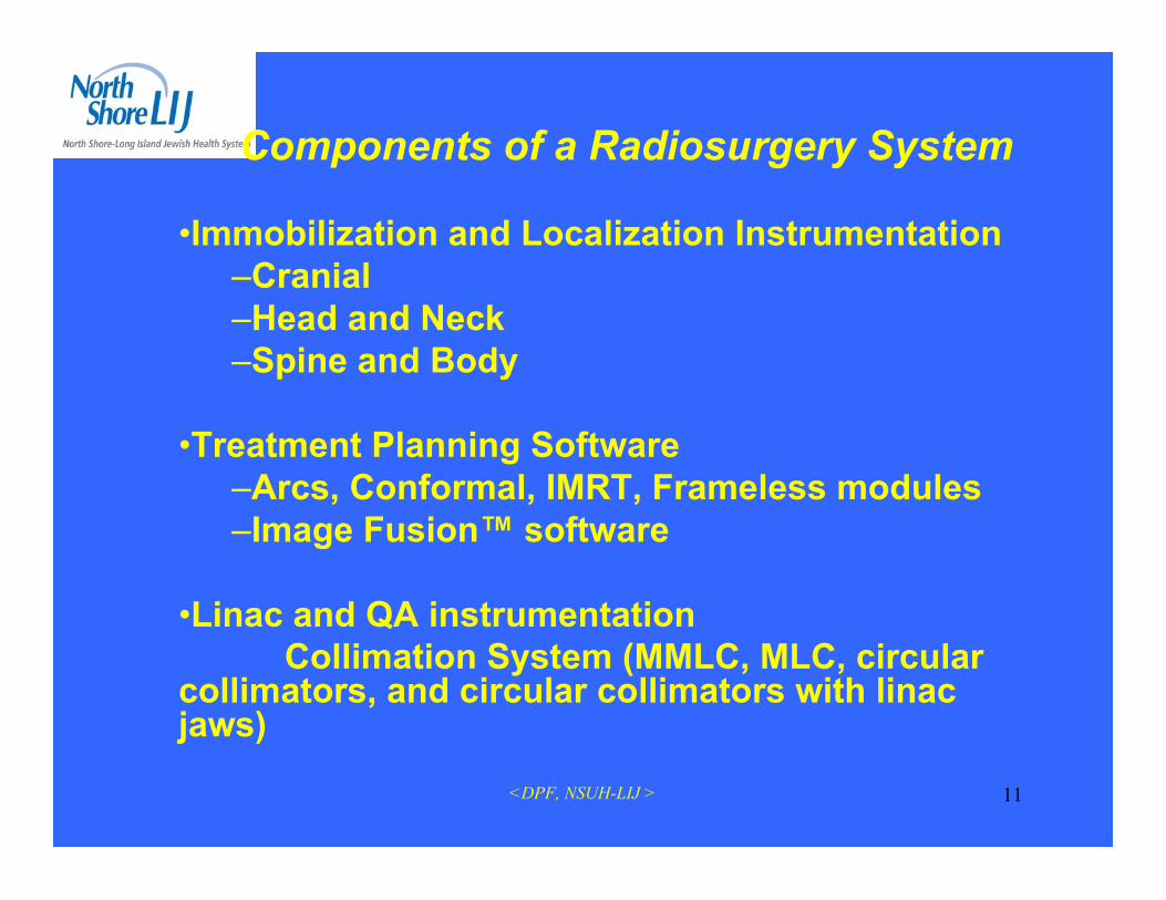
Components of a Radiosurgery System
•Immobilization and Localization Instrumentation–Cranial–Head and Neck–Spine and Body
•Treatment Planning Software–Arcs, Conformal, IMRT, Frameless modules–Image Fusion™ software
•Linac and QA instrumentationCollimation System (MMLC, MLC, circular
collimators, and circular collimators with linacjaws)

<DPF, NSUH-LIJ > 12
Stereotactic Hardware(Brain Lab)

<DPF, NSUH-LIJ > 13
• Quick and easy mounting using a dedicated storage trolley
• Gantry at 180° position
• Immediate electronic and power connection
• Full communication and safetyinterlocks with Varian, Elekta andSiemens Linacs for IMRT anddynamic conformal arc treatment
m3 Linac Attachment
<DPF, NSUH-LIJ > 14
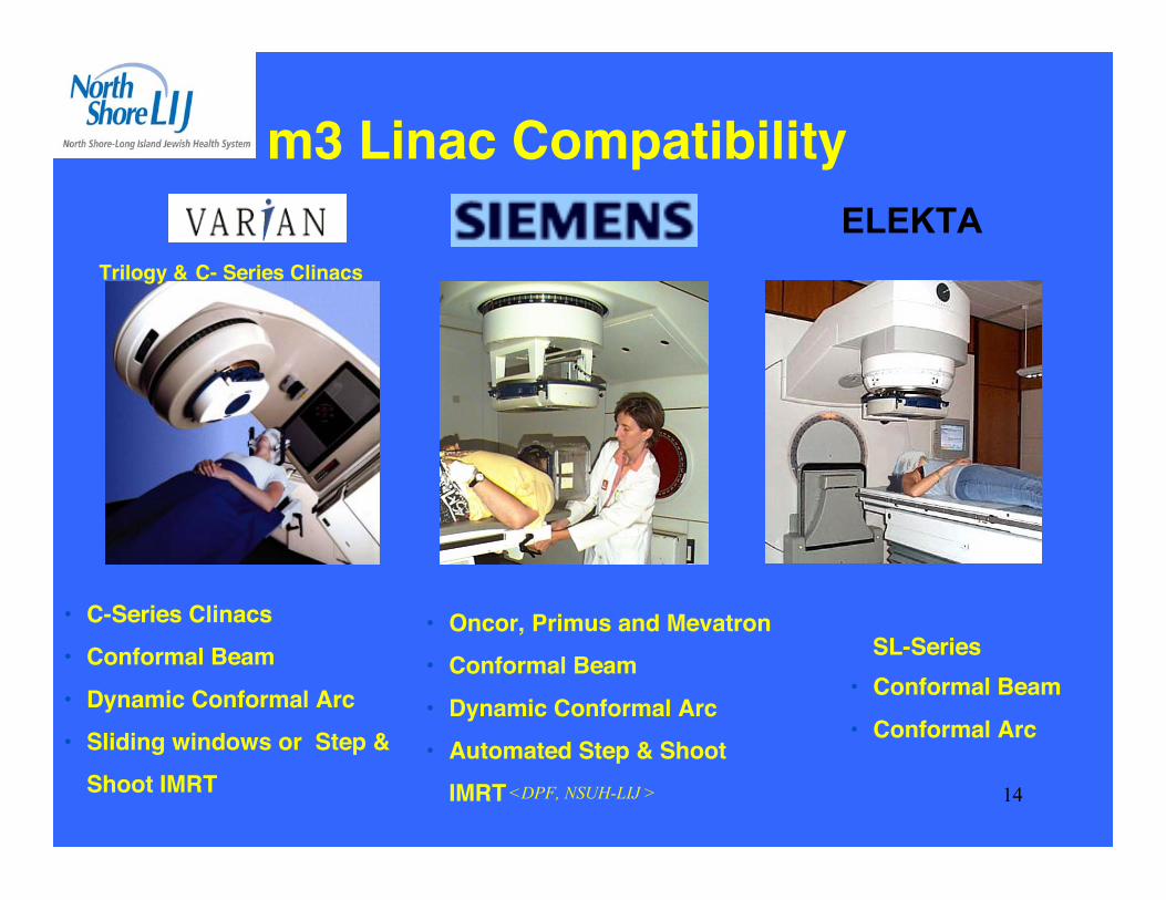
• C-Series Clinacs• Conformal Beam• Dynamic Conformal Arc• Sliding windows or Step &
Shoot IMRT
m3 Linac Compatibility
• Oncor, Primus and Mevatron• Conformal Beam• Dynamic Conformal Arc• Automated Step & Shoot
IMRT
SL-Series• Conformal Beam• Conformal Arc
Trilogy & C- Series Clinacs
ELEKTA

<DPF, NSUH-LIJ > 15
Elekta
Linac Compatibility
•Siemens:Oncor, Primus& Mevatron
•Varian (Trilogy & C-Series)•TomoTherapy

<DPF, NSUH-LIJ > 16
Radiosurgery
ExacTrac® X-Ray 6D
m3®
mMLC

<DPF, NSUH-LIJ > 17

<DPF, NSUH-LIJ > 18
CHARACTERISTICS OF STEREOTATIC(SRS) and (SRT)
• STEREOTACTIC COORDINATE SYSTEM(CRW, BRW) (CT, MRI, Angiography) (Linac)
allows accurate dose delivery to the target
• SHARP DOSE GRADIENTS AT FIELD EDGES :( Dose falls of to 50% of target dose within 3 - 4 mm)
• HIGHLY CONCENTRATED RADIATION DOSE :multiple non-coplanar arcs converging at theisocenter.

<DPF, NSUH-LIJ > 19
SRS/SRT General Procedure• Diagnostic MR images of patient• Target/Organs contouring• Pre-plan using MR images (whenever
allowed by Tx plan software)• Placement of Head Ring• Stereotactic CT/Angio images• Transfer images to Tx Plan workstation• Fuse MR to CT images (optional)• Treatment Planning• QA of LINAC (previous to Tx.)• Verify correctness of Pt. Position• Treat patient

<DPF, NSUH-LIJ > 20
m3 Treatment
PatientTreatment Completed
Patient fixation Imaging
Planning
Set-Up
15 min.
30 min.
10 min.
30 min.15 min.
Start
RadiosurgeryClinical Procedure
<DPF, NSUH-LIJ > 21
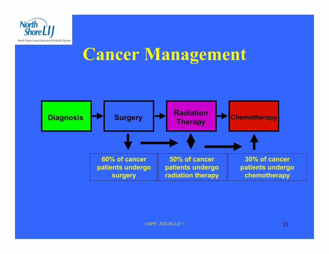
Cancer Management
Diagnosis RadiationTherapy Chemotherapy
60% of cancerpatients undergo
surgery
50% of cancerpatients undergoradiation therapy
30% of cancerpatients undergo
chemotherapy
Surgery

<DPF, NSUH-LIJ > 22
Rationale for StereotacticRadiotherapy
• Reduces risk of healthy brain and cranialnerve damage
• Allows for treatment in/or near critical areas(e.g., retina, brain stem, chiasm)
• Allows for safe treatment of larger lesions(> 3-5 cm.)

<DPF, NSUH-LIJ > 23
Role of Radiosurgeryin the Management of Intracranial
Tumors• Potentially curative therapy in benign, non-invasive
tumors (pituitary adenomas, acoustic neuroma,meningioma, pilocytic astrocytoma).
• Adjuvant Therapy (Boost) for Benign or MalignantTumors (metastasis, glioma, medulloblastoma,ependymoma) .
• Preoperative Therapy for Vascular Tumors• Salvage Therapy for previously irradiated recurrent
tumors.

<DPF, NSUH-LIJ > 24
INDICATIONS FOR STEREOTACTICSRS/SRT
• Acoustic Tumors (Schwannomas, Neuromas,Neurinomas, Nerve sheath tumors, Neurilemomas)
• Arteriovenous Malformations• Arteriovenous Malformations• Arterial Aneurysms• Craniopharyngiomas• Ependymomas• Glomus Jugulare Tumors• Hemangioblastoma• Medulloblastomas (Boost)• Meningiomas

<DPF, NSUH-LIJ > 25
INDICATIONS FOR STEREOTACTICSRS/SRT
• Metastases• Optic Gliomas• Pinealomas• Pituitary Adenomas• Primary Brain Tumors (Glioblastomas,
Astrocytomas,CNS Sarcoma, CNS Lymphoma)• Retinoblastomas• Venous Angiomas• Functional Radiosurgery• Clinical studies for use in Parkinson’s and Epilepsy

<DPF, NSUH-LIJ > 26
Typical Indications for Radiosurgery
Images courtesy of:1) UCLA, 2) Universitätsklinikum Charité Berlin, 3) Helios Klinikum Erfurt, 4) University of Rochester
Pre-SRS / 36 mth follow-up
AVM1 Brain Metastasis1 High GradeGlioma2 Meningioma3Low Grade Glioma1 Multiple Lung
Metastasis4

<DPF, NSUH-LIJ > 27
Radiosurgery - MetastasisPre-Radiosurgery Post-Radiosurgery
6 months

<DPF, NSUH-LIJ > 28
Radiosurgery AVMPre-Radiosurgery
6months
Post-Radiosurgery

<DPF, NSUH-LIJ > 29
Clinical Indications for SRS / SRT
50%25%
15% 9% 1%
Malignant Tumors, 50% - Metastatic tumors, primary andrecurrent gliomasBenign Tumors, 25% - Meningiomas, acoustic neuromas, pituitaryadenomas, craniopharyngiomasVascular Disease, 15% - AVMs, cavernous angiomasPediatric Tumors, 9% - RetinoblastomasFunctional Disease, 1%
1997 Study. Courtesy Jay Loeffler, M.D., Harvard Medical School, Boston, MA

<DPF, NSUH-LIJ > 30
Stereotactic Radiotherapy
• A hybrid technique thatcombines the benefits ofconventionalradiotherapy with thebenefits of stereotaxy.
<DPF, NSUH-LIJ > 31
PHYSICAL COMPONENTS REQUIREDFOR SRS/SRT
1. Laser-Angiographic Target Localizer (LATL)2. BRW (CRW) CT /MR Localizer Frame3. Relocatable Head Frame (GTC)4. Patient Positioning Devices:
• Rectilinear Phantom Pointer (RLPP)• Laser Target Localizer Frame (LTLF)• Linac Couch Mount Adapter (LCMA)
5. Depth Confirmation Helmet (QA)

<DPF, NSUH-LIJ > 32
SRS
SRT (GTC)(Gill-Thomas-Cosman)relocatble head frame
Placement of Head Ring

<DPF, NSUH-LIJ > 33
Stereotactic Patient Set-upCT Localizer
• For CT / X-Ray localization
• Links Angio Images to CT
• Creates stereotactic coordinatesystem
• Large scan range (185 mm)
• No fixation to CT couch
• Not required in MR

<DPF, NSUH-LIJ > 34
Stereotactic CT scan forSRS
<DPF, NSUH-LIJ > 35
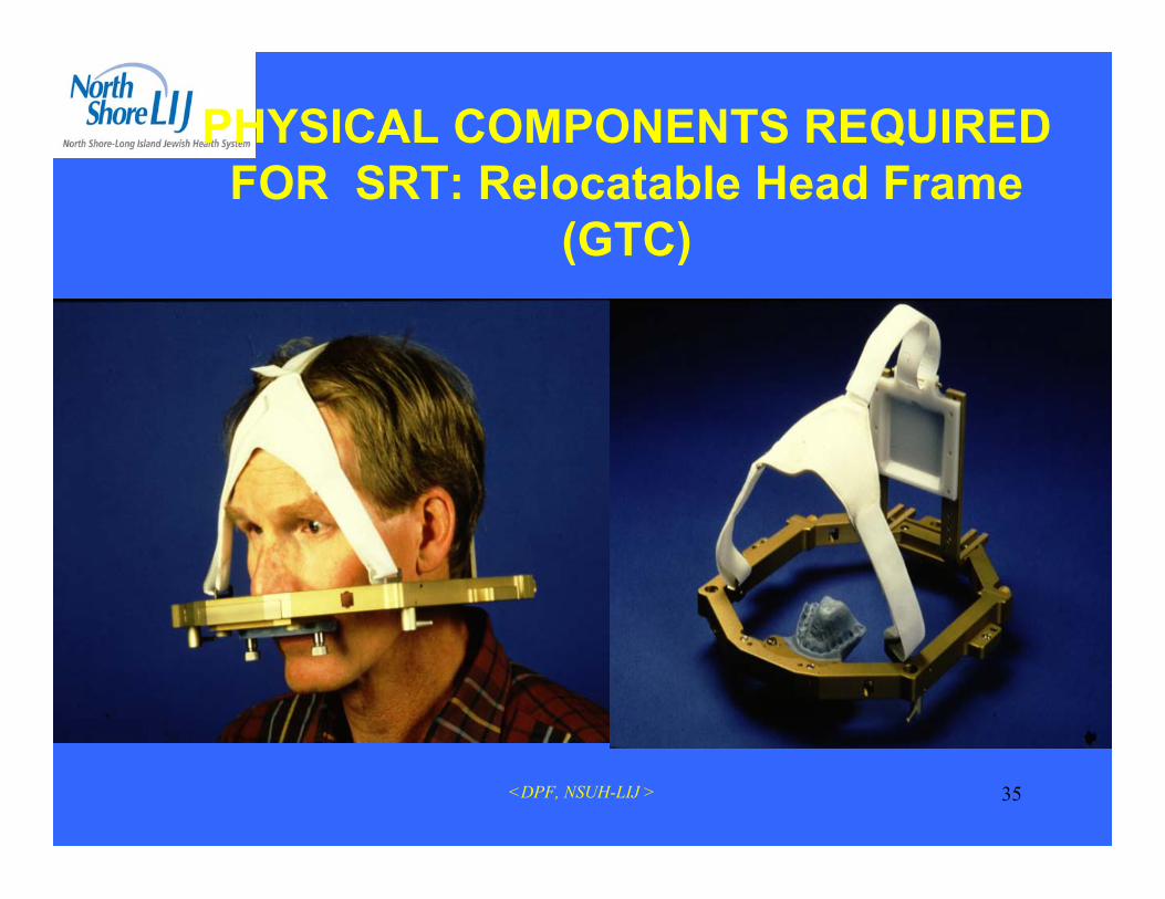
PHYSICAL COMPONENTS REQUIREDFOR SRT: Relocatable Head Frame
(GTC)

<DPF, NSUH-LIJ > 36
Image FusionCT
MRI
MRI

<DPF, NSUH-LIJ > 37
3 piece Mask System,Extends treatment area to T1Set-up errors from 1.7 to 0.9 mm3 indexed differently sized bite platesComplete carbon fiber,Tilt compensation for set-upSuitable for elderly patients & children
Patient positioning accuracy in a thermoplastic mask with upper jaw support.J. Ahlswede et al. AAPM Annual Meeting 2001 Poster Display
Patient Immobilization (SRT)

<DPF, NSUH-LIJ > 38
PHYSICAL COMPONENTS REQUIREDFOR SRS/SRT
TREATMENT PLANNING SYSTEM:
• Calculates and displaysa 3D dose distributionbased on the patient’sanatomy within thestereotactic frame

<DPF, NSUH-LIJ > 39
Basic requirements for SRS Dosimetry(Linac Based)
• Accurate localization:– 1mm (angiography,CTA), 2mm (CT, MRI)
• Mechanical Precision: Stability of Linac– Gantry, Collimator & PSA axis of rotation (1mm radius).– Lasers: (2 Lats, 1 @ceiling) Must be parallel and coincide @
isocenter <1mm.
• Accurate and Optimal Dose Distribution:– (<5%). Must be tested in humanoid phantom.
• Patient Safety:– Machine Interlocks. Gantry rotation, Secondary collimators &
Couch motion disabled– Vernier based fine adjustment: allow alignment within ~1m

<DPF, NSUH-LIJ > 40
Winston Lutz Quality Assurance
Stereotactic Set-up QA. (Linac)
• Phantom Pointer verifies laseraccuracy prior to SRS
• Embossed laser lines for easyalignment with wall lasers
• Integrated tungsten sphere for filmverification
• Irradiation of film at different gantryangles
• Shadow in field center verifiesaccuracy

<DPF, NSUH-LIJ > 41
QA of Isocenter

<DPF, NSUH-LIJ > 42
SRX TARGET LOCALIZATION UNCERTAINTY
Machine: 600 CSRX cone: 1.25 cm diameter.SFD: 125 cmFilm type: X Omat L.Monitor units: 4Setup: Coordinates for SRX frames
AP LAT VERtRLPP 0.00 0.00 0.00LTLF 0.00 0.00 0.00
Patient coordinates notation: (supine configuration):A: Anterior; P: Posterior; L: left; R: right; S: superior; I: inferior.Procedure:
1. Laser wall marks verified.2. RLPP set with laser target localization tool (lateral and ceiling lasers in the
middle of the cross).3. Vertical, longitudinal and lateral couch movements locked.4. LTLF used to verify setup (Note: lateral lasers on the middle of lateral laser
crosses. Ceiling laser displaced from center of the cross to the left line andsuperiorly out of the cross as regularly found on the anterior vertical vernier).
5. Laser target tool replaced by target localization ball.6. LTLF removed and film irradiated as indicated in the following table.
Couch 0° 0° 0° 0° 90° 90° 270° 270°Gantry 0° 180° 90° 270° 0° 180° 0° 180°
AP(mm) --- --- +0.1 A -0.7 P --- --- --- ---LR(mm) -0.6 L +0.2 R --- --- +0.5 R -0.8 L 0.0 +1.2 RSI(mm) +1.0 S 0.0 +0.3 S +0.4 S 0.0 +1.0 S +0.4 S -0.5 I
Note: Measurements done on the film (not at isocenter), using Wellhofer WP 700 filmdosimetry program.
Detailed dosimetry results are attached to the original report kept in RadionicsAcceptance Book (2001+).

<DPF, NSUH-LIJ > 43External Target
QA of Pt Position

<DPF, NSUH-LIJ > 44
External Target Localization - Pt Position QA:Measure: BRW Localizer frame, on the CT & on theTx. Plan)
RLPP
BRW Localizer Frame
ExternalTarget

<DPF, NSUH-LIJ > 45
Stereotactic Frames and QA
Frames for SRS Applications:
Brown-Roberts-Wells (BRW)
Tipal
Leksel
Gill-Thomas-Cosman(GTC)
Riechert-Mundinger

<DPF, NSUH-LIJ > 46
Beam Dose Measurements
• Problem w/ small field dosimetry:– Detector size & Small field dimensions– Lack of equilibrium in lateral charged particles– Large dose gradients in SRS penumbra
• Equipment:– Water tank, polystyrene slabs, ion chamber,diodes,
TLD’s and Film– Detector diameter < 3.5mm(reproduce penumbra ~1mm)
<DPF, NSUH-LIJ > 47
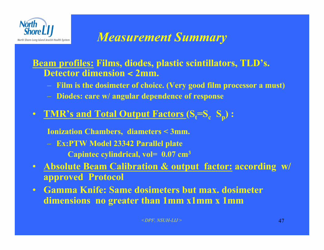
Measurement Summary
Beam profiles: Films, diodes, plastic scintillators, TLD’s.Detector dimension < 2mm.– Film is the dosimeter of choice. (Very good film processor a must)– Diodes: care w/ angular dependence of response
• TMR’s and Total Output Factors (St=Sc Sp) :
Ionization Chambers, diameters < 3mm.– Ex:PTW Model 23342 Parallel plate Capintec cylindrical, vol= 0.07 cm3
• Absolute Beam Calibration & output factor: according w/approved Protocol
• Gamma Knife: Same dosimeters but max. dosimeterdimensions no greater than 1mm x1mm x 1mm

<DPF, NSUH-LIJ > 48
Pin-Point Chamber: Waterproof thimble chamber formeasuring in air, water and phantom material: * Vented sensitive volume: 0.125 cm3 and 0.3 cm3
* Suitable for use in water phantoms, w/ photons& electrons. Flat energy response within a wideenergy range.

<DPF, NSUH-LIJ > 49
Coll=12.5mm
Coll=22.5mm
Coll=30.0 mm
Welhofer
o Laser Film Digitizer(Lumisys)
Film Digitizer
Beam Profiles

<DPF, NSUH-LIJ > 50
Gamma Knife
Beam profiles

<DPF, NSUH-LIJ > 51
TMR Curves

<DPF, NSUH-LIJ > 52
Stereotatic Output Factor Curve(St=Sc Sp)
@ Isocenter, dmax
6 MV
Coll. Diam.:12.5mm to 20.0mm

<DPF, NSUH-LIJ > 53
Dose Evaluation Tools•Volume Dose
•Surface Dose
•Dose Summary
•Slice Dose
•Dose Volume Histograms
•Tissue-Volume-Ratio (TVR)

<DPF, NSUH-LIJ > 54
Radiologic Physics Center (RPC)Anthropomorphic Phantom
•Phantom has 2 inserts:
•One for imaging: CT,MRI•One for Dosimetry w/TLD’s andgraphchromic film
<DPF, NSUH-LIJ > 55
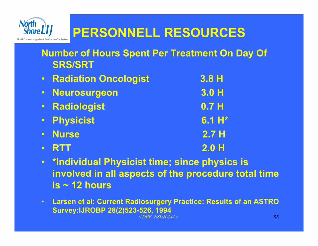
PERSONNELL RESOURCESNumber of Hours Spent Per Treatment On Day Of
SRS/SRT• Radiation Oncologist 3.8 H• Neurosurgeon 3.0 H• Radiologist 0.7 H• Physicist 6.1 H*• Nurse 2.7 H• RTT 2.0 H• *Individual Physicist time; since physics is
involved in all aspects of the procedure total timeis ~ 12 hours
• Larsen et al: Current Radiosurgery Practice: Results of an ASTROSurvey:IJROBP 28(2)523-526, 1994

<DPF, NSUH-LIJ > 56
IntegrationModular architecture for software
and hardware integration
Upgradeability– Continual software development– Upgrade path for new features
and applications
Radiosurgery1997: m3
2002: NovalisBody
1998: Dynamicconformal arcs
2000: IMRT
1999: ExacTrac
2005: AdaptiveGating

<DPF, NSUH-LIJ > 57
Dynamic Conformal ArcDynamic Conformal Arcs
• Automatic leaf adaptation to tumorcontour
• Straight-forward arc optimizationwith collision map
• Possible with std. Varian MLC,m3 on Varian or Siemens LinacsBenefits:• Fast, semi-automatic single isocenter
treatment planning• Critical structures are automatically
spared for all beam angles• Most conformal and homogeneous
dose distribution with reducedirradiation of normal tissue

<DPF, NSUH-LIJ > 58
Conformal mMLC Plan1 Isocenter -6 StaticFields
Dynamic Conformal Arc Plan1 Isocenter - 3 Dynamic Arcs
4.64
3.69 0.
64
0.53
0
0.5
1
1.5
2
2.5
3
3.5
4
4.5
5
50% Isodose 90 % Isodose
6 Conf. Beams
3 Dynamic Arcs
Volume of irradiatedNormal Tissue (cm_)
Clinical Results
Courtesy of Universitätsklinkum Charité, Berlin

<DPF, NSUH-LIJ > 59
Dynamic Arc Radiosurgery Field Shaping: A Comparison with Static Field Conformaland non-coplanar circular arcs. T. Solberg et al. Int. J. Radiation Oncology Biol Physics.Vol 49, No. 5, pp1481–1491, 2001
Dynamic ConformalArc, 5 Arcs (1 isocenter)Conformal Beam,
19 Beams (1 isocenter)
4.0 Gy10.0 Gy18.0 Gy
Circular Arc,8 Isocenters
7.2 Gy18.0 Gy
Clinical ResultsAcoustic Neuroma
Improved normal tissue sparingTight margin around target

<DPF, NSUH-LIJ > 60
Clinical ResultsAcoustic Neuroma
Homogenous Dose Distribution Greater sparing of normal tissue and risk structures
Lesion
0,00,20,40,60,81,01,21,41,61,82,0
0 5 10 15 20 25 30 35
Multi-IsoConformalDynamic
Dose (cGy)
Brainstem
0
5
10
15
20
25
0 5 10 15 20
Multi-IsoConformalDynamic
Normal Brain
0
200
400600
800
1000
12001400
1600
1800
0 2 4 6 8 10
Multi-IsoConformalDynamic
Volu
me
(cm
3 )
Dose (cGy)
Volu
me
(cm
3 )
Dose (cGy)
Volu
me
(cm
3 )Dynamic Arc Radiosurgery Field Shaping: A Comparison with Static Field Conformaland non-coplanar circular arcs. T. Solberg et al. Int. J. Radiation Oncology Biol Physics.Vol 49, No. 5, pp1481–1491, 2001
<DPF, NSUH-LIJ > 61
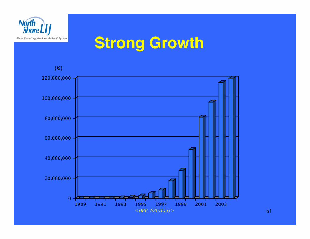
Strong Growth(€)
0
20,000,000
40,000,000
60,000,000
80,000,000
100,000,000
120,000,000
1989 1991 1993 1995 1997 1999 2001 2003

<DPF, NSUH-LIJ > 62

<DPF, NSUH-LIJ > 63
1:Ding GX, Duggan DM, Coffey CW.: Commissioning stereotactic radiosurgery beams using bothexperimental and theoretical methods. Phys Med Biol. 2006 May 21;51(10):2549-66.
2: Sánchez-Doblado F, Andreo P, Capote R, Leal A, Perucha M, Arráns R, Núñez L, Mainegra E, LagaresJI, Carrasco E :Phys Med Biol. 2003 Jul 21;48(14):2081-99. Comment in: Phys Med Biol. 2003 Nov7;48(21):L43-5; author reply L46-8. Ionization chamber dosimetry of small photon fields: a Monte Carlostudy on stopping-power ratios for radiosurgery and IMRT beams.
3: Araki F.: Monte Carlo study of a Cyberknife stereotactic radiosurgery system. Med Phys. 2006Aug;33(8):2955-63: Kumamoto University School of Health Sciences, Kumamoto, 862-0976, Japan.Department of Radiological Technology,
4: Cosgrove VP, Jahn U, Pfaender M, Bauer S, Budach V, Wurm RE, Germany Radiother Oncol. 1999Mar;50(3):325-36 : Commissioning of a micro multi-leaf collimator and planning system for stereotacticradiosurgery. Klinik für trahlentherapie, Universitätsklinikum Charité, Berlin,
5: Belec J, Patrocinio H, Verhaegen F.: Development of a Monte Carlo model for the BrainlabmicroMLC.Phys, Med Biol. 2005 Mar 7;50(5):787-99.
6: Li S, Rashid A, He S, Djajaputra D. A new approach in dose measurement and error analysis for narrowphoton beams (beamlets) shaped by different multileaf collimators using a small detector.Med Phys. 2004Jul;31(7):2020-32.
7.Sánchez-Doblado F, Andreo P, Capote R, Leal A, Perucha M, Arráns R, Núñez L, Mainegra E, LagaresJI, Carrasco E.: Ionization chamber dosimetry of small photon fields: a Monte Carlo study on stopping-power ratios for radiosurgery and IMRT beams. Phys Med Biol. 2003 Jul 21;48(14):2081-99.

<DPF, NSUH-LIJ > 64
8:Deng J, Ma CM, Hai J, Nath R. :Commissioning 6 MV photon beams of astereotactic radiosurgery system for Monte Carlo treatment planning. MedPhys. 2003 Dec;30(12):3124-34.
9: Paskalev KA, Seuntjens JP, Patrocinio HJ, Podgorsak EB.: Physicalaspects of dynamic stereotactic radiosurgery with very small photon beams(1.5 and 3 mm in diameter). Med Phys. 2003 Feb;30(2):111-8.
10: Sikora M,Dohm ),alber M.:A virtual photon source model of an Elektalinear accelerator with integrated mini MLC for Monte Carlo based IMRTdose calculation. Phys Med Biol. 2007 Aug 7;52(15):4449-63. Epub 2007 Jun26.
11: De Vlamynck K, Palmans H, Verhaegen F, De Wagter C, De Neve W,Thierens H.: Dose measurements compared with Monte Carlo simulations ofnarrow 6 MV multileaf collimator shaped photon beams. Med Phys. 1999Sep;26(9):1874-82.
12: Cosgrove VP, Jahn U, Pfaender M, Bauer S, Budach V, WurmRE.:Commissioning of a micro multi-leaf collimator and planning system forstereotactic radiosurgery. Radiother Oncol. 1999 Mar;50(3):325-36.
13: Verhaegen F, Das IJ, Palmans H.: Monte Carlo dosimetry study of a 6 MVstereotactic radiosurgery unit.Phys Med Biol. 1998 Oct;43(10):2755-68
14: Wang L, Li J, Paskalev K, Hoban P, Luo W, Chen L, McNeeley S, PriceR, Ma C.: Commissioning and quality assurance of a commercial stereotactictreatment-planning system for extracranial IMRT.J Appl Clin Med Phys. 2006 Winter;7(1):21-34. Epub 2006 Feb 15.
15: Chaves A, Lopes MC, Alves CC, Oliveira C, Peralta L, Rodrigues P,Trindade A.: Basic dosimetry of radiosurgery narrow beams using MonteCarlo simulations: a detailed study of depth of maximum dose.Med Phys. 2003 Nov;30(11):2904-11.

<DPF, NSUH-LIJ > 65
16: Crop F, Reynaert N, Pittomvils G, Paelinck L, De Gersem W, DeWagter C, Vakaet L, De Neve W, Thierens H.: Monte Carlo modeling ofthe ModuLeaf miniature MLC for small field dosimetry and qualityassurance of the clinical treatment planning system.Phys Med Biol. 2007 Jun 7;52(11):3275-90
17: 7:Paskalev KA, Seuntjens JP, Patrocinio HJ, Podgorsak EB.:Physical aspects of dynamic stereotactic radiosurgery with very smallphoton beams (1.5 and 3 mm in diameter).Med Phys. 2003 Feb;30(2):111-8.
18:Sikora M, Dohm O, Alber M. :A virtual photon source model of anElekta linear accelerator with integrated mini MLC for Monte Carlobased IMRT dose calculation.Phys Med Biol. 2007 Aug 7;52(15):4449-63.
<DPF, NSUH-LIJ > 66
Thank you