step 5: create sweep-torus feature: features tab > swept
TRANSCRIPT
Chapter 4: Features and Macros 105
Step 5: Create Sweep-Torus feature: Features tab > Swept Boss/base > select Sketch3-Profile as the Profile > select Sketch1-Path as the Path > select Sketch2-Guide as the Guide Curve > ✔.
4.3 Spur Gears
Gears are an important and essential mechanical element in mechanical design. A wide range of products and applications uses gears. There are various types of gears: spur, helical, bevel, spiral, worm, planetary, and rack and pinion, to name a few. Spur gear is the simplest type of gear, which we cover here. Typical mechanical design courses in colleges cover the principles and design of gears. In this section, we cover spur gears from a CAD point of view (i.e., how we construct a gear once it is designed). While gears are standard elements that can be purchased off the shelf (they can also be inserted from SolidWorks Toolbox into a part or assembly file), it is important to learn how to create a gear feature in a CAD/CAM system.
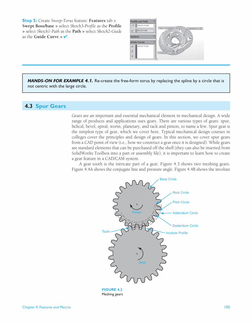
A gear tooth is the intricate part of a gear. Figure 4.3 shows two meshing gears. Figure 4.4A shows the conjugate line and pressure angle. Figure 4.4B shows the involute
HANDS-ON FOR EXAMPLE 4.1 . Re-create the free-form torus by replacing the spline by a circle that is not centric with the large circle.
Base Circle
Root Circle
Pitch Circle
Dedendum Circle
+
+
Pinion
Gear
Involute ProfileTooth
Addendum Circle
FIGURE 4.3 Meshing gears

106 Chapter 4: Features and Macros
profile. Gearing and gear meshing ensure that two disks (the two gears) in contact roll against one another without slipping. Moreover, the gear teeth should not interfere with the uniform rotation that one gear would induce in the other, a requirement known as the conjugate action. The conjugate action also ensures that the perpendicular line to a tooth profile at its point of contact with a tooth from the other gear always passes through a fixed point on the centerline connecting the centers of the two meshing gears. Figure 4.4A shows the conjugate line. The conjugate line is also known as the line of force because the driving force from the driving gear (driver) is transmitted in the direction of this line to the other gear (driven). The angle between the perpendicular radius to the conjugate line and the centerline is always constant for two meshing gears. This angle is known as the pressure angle and is shown as the angle Ø in Figure 4.4A .
The key to successful functional gears is the conjugate action. While various profiles can produce conjugate action, the involute profile is the best because it allows for imper-fections in gear manufacturing and yet maintains the conjugate action. The imperfection may produce a slightly different distance between the two shafts of the gears from the designed value. Figure 4.4B shows how the shape of the involute profile is generated. An involute is defined as the path of the end point of a cord when it is pulled straight (held taut) and unwrapped from a circular disk as shown in Figure 4.4B . The involute geom-etry ensures that a constant rotational speed of the driving gear produces a constant rotational speed in the driven gear. For spur gears, the teeth are cut perpendicular to the plane of the gear, where the involute profile resides.
The creation of a gear CAD model requires two basic concepts: knowledge of the gear geometry and the involute equation. The geometry is shown in Figure 4.3 . The
Cord
Base Circle
Involute
+
(B) Involute profile
+
rb
rp
Circular Pitch pc
pc 2
�
2�
AddendumCircle
Pitch Circle
Base Circle
(C) Tooth angle
Pb
Y
�
X
rb
a
d
Pa
P (x, y)
(D) Involute coordinate system
FIGURE 4.4 Details of a gear tooth
Base Circle
Point of Contactof Gear Teeth
Line of Force(conjugate line)
Pressure Angle
Pitch Circle
φ
rb
rp
+
+
(A) Conjugate action
Chapter 4: Features and Macros 107
base circle is the circle where the involute profile begins. The pitch circle defines the contact (pitch) point between the two gears (see Figure 4.4A ). The dedendum circle is usually the same as the base circle, as can be concluded from Figure 4.3 A (dedendum d � r p – r b ). The addendum circle is the circle that defines the top of the tooth as shown in Figure 4.4C (addendum a � r a � r p , where r a is the addendum circle radius). Typi-cally, the addendum and the dedendum are equal. In such case, the pitch and base circle sizes determine the values for both. The root circle is smaller than the base circle to allow cutting the tooth during manufacturing. The tooth profile between the base and root circles is not an involute. It could be any geometry such as line.
The creation of a gear CAD model requires two steps: calculate the tooth angle � and the tooth involute profile. While many books on mechanical engineering design offer extensive in-depth coverage of gear analysis, we offer a simplified, but accurate, version to enable us to create a CAD model of the gear. We begin with the definition of circular pitch. As shown in Figure 4.4C , the circular pitch , p c , is defined as the distance along the pitch circle between corresponding points on adjacent teeth. As shown in Figure 4.4C , we use p c as the circular pitch of the gear, r p as the pitch circle radius, and � as the tooth angle. Using these variables, we can write:
pc � �dp
N (4.1)
Where d p � 2r p is the pitch circle diameter, and N is the number of gear teeth. From the tooth geometry shown in Figure 4.4C , we can write:
pc
2 � rp� (4.2)
Substituting p c from Eq. (4.2) into Eq. (4.1) and reducing gives:
� � �
N radians or � �
180
N degrees (4.3)
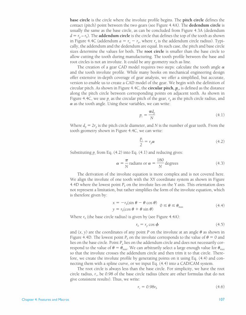
The derivation of the involute equation is more complex and is not covered here. We align the involute of one tooth with the XY coordinate system as shown in Figure 4.4D where the lowest point P b on the involute lies on the Y axis. This orientation does not represent a limitation, but rather simplifies the form of the involute equation, which is therefore given by:
x � �rb(sin � � � cos �)
y � rb(cos � � � sin �) 0 � � � �max
(4.4)
Where r b (the base circle radius) is given by (see Figure 4.4A ):
rb � rp cos � (4.5)
and ( x , y ) are the coordinates of any point P on the involute at an angle � as shown in Figure 4.4D . The lowest point P b on the involute corresponds to the value of � � 0 and lies on the base circle. Point P a lies on the addendum circle and does not necessarily cor-respond to the value of � � � max . We can arbitrarily select a large enough value for � max so that the involute crosses the addendum circle and then trim it to that circle. There-fore, we create the involute profile by generating points on it using Eq. (4.4) and con-necting them with a spline curve, or we input Eq. (4.4) into a CAD/CAM system.
The root circle is always less than the base circle. For simplicity, we have the root circle radius, r r , be 0.98 of the base circle radius (there are other formulas that do not give consistent results). Thus, we write:
rr � 0.98rb (4.6)
108 Chapter 4: Features and Macros
The following steps summarize the calculations we need to create a gear CAD model:
1. The input parameters we need are the pitch circle radius r p , the pressure angle Ø , and the gear number of teeth N.
2. Calculate r b using Eq. (4.5) . 3. Calculate r r using Eq. (4.6) . 4. Calculate the gear dedendum d � r p � r b . 5. Assuming that the addendum and dedendum are equal, calculate the addendum
circle radius as r a � r p � a � r p � d (see Figures 4.4C and 4.4D ). 6. Use Eq. (4.3) to calculate the tooth angle �. 7. Enter the involute parametric equation given by Eq. (4.4) into a CAD/CAM system
to sketch the involute curve as a spline. 8. Create one gear tooth and use sketch circular pattern to pattern it to create all gear
teeth.
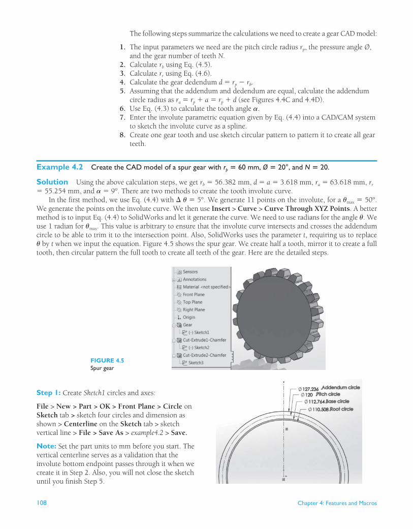
Example 4.2 Create the CAD model of a spur gear with r p � 60 mm, Ø � 20°, and N � 20.
Solution Using the above calculation steps, we get r b � 56.382 mm, d � a � 3.618 mm, r a � 63.618 mm, r r � 55.254 mm, and � � 9°. There are two methods to create the tooth involute curve.
In the first method, we use Eq. (4.4) with � � � 5°. We generate 11 points on the involute, for a � max � 50°. We generate the points on the involute curve. We then use Insert > Curve > Curve Through XYZ Points . A better method is to input Eq. (4.4) to SolidWorks and let it generate the curve. We need to use radians for the angle �. We use 1 radian for � max . This value is arbitrary to ensure that the involute curve intersects and crosses the addendum circle to be able to trim it to the intersection point. Also, SolidWorks uses the parameter t , requiring us to replace � by t when we input the equation. Figure 4.5 shows the spur gear. We create half a tooth, mirror it to create a full tooth, then circular pattern the full tooth to create all teeth of the gear. Here are the detailed steps.
FIGURE 4.5 Spur gear
Step 1: Create Sketch1 circles and axes: File > New > Part > OK > Front Plane > Circle on Sketch tab > sketch four circles and dimension as shown > Centerline on the Sketch tab > sketch vertical line > File > Save As > example4.2 > Save.
Note: Set the part units to mm before you start. The vertical centerline serves as a validation that the involute bottom endpoint passes through it when we create it in Step 2. Also, you will not close the sketch until you finish Step 5.
Chapter 4: Features and Macros 109
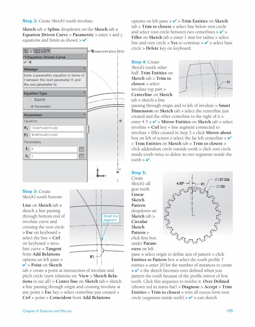
Step 2: Create Sketch1 -tooth involute: Sketch tab > Spline dropdown on the Sketch tab > Equation Driven Curve > Parametric > enter x and y equations and limits as shown > ✔.
options on left pane > ✔ > Trim Entities on Sketch tab > Trim to closest > select line below root circle and select root circle between two centerlines > ✔ > Fillet on Sketch tab > enter 1 mm for radius > select line and root circle > Yes to continue > ✔ > select base circle > Delete key on keyboard.
Step 4: Create Sketch1 -tooth other half: Trim Entities on Sketch tab > Trim to closest > select involute top part > Centerline on Sketch tab > sketch a line passing through origin and to left of involute > Smart Dimension on Sketch tab > select the centerline just created and the other centerline to the right of it > enter 4.5 > ✔ > Mirror Entities on Sketch tab > select involute + Ctrl key + line segment connected to involute + fillet created in Step 3 > click Mirror about box on left of screen > select the far left centerline > ✔ > Trim Entities on Sketch tab > Trim to closest > click addendum circle outside tooth > click root circle inside tooth twice to delete its two segments inside the tooth > ✔.
Step 5: Create Sketch1 -all gear teeth: Linear Sketch Pattern dropdown on Sketch tab > Circular Sketch Pattern > click first box under Param-eters on left pane > select origin to define axis of pattern > click Entities to Pattern box > select the tooth profile 7 entities > enter 20 for the number of instances to create > ✔ > the sketch becomes over defined when you pattern the tooth because of the profile mirror of first tooth. Click this sequence to resolve it: Over Defined (shown red in status bar) > Diagnose > Accept > Trim Entities > Trim to closest > trim all excess form root circle (segments inside teeth) > ✔ > exit sketch.
Step 3: Create Sketch1 -tooth bottom:
Line on Sketch tab > sketch a line passing through bottom end of involute curve and crossing the root circle > Esc on keyboard > select the line + Ctrl on keyboard + invo-lute curve > Tangent from Add Relations options on left pane > ✔ > Point on Sketch tab > create a point at intersection of involute and pitch circle (turn relations on: View > Sketch Rela-tions to see all) > Center line on Sketch tab > sketch a line passing through origin and crossing involute at any point > Esc key > select centerline just created + Ctrl + point > Coincident from Add Relations
Small linesegment
110 Chapter 4: Features and Macros
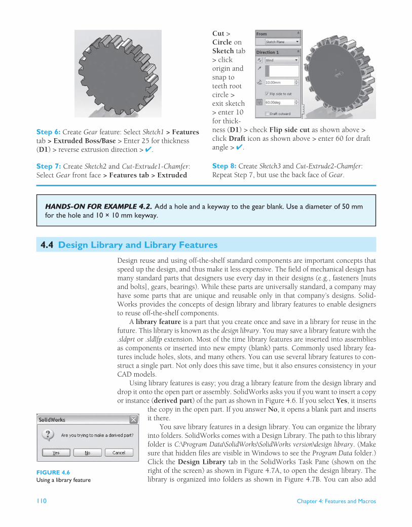
Step 6: Create Gear feature: Select Sketch1 > Features tab > Extruded Boss/Base > Enter 25 for thickness ( D1 ) > reverse extrusion direction > ✔. Step 7: Create Sketch2 and Cut-Extrude1-Chamfer : Select Gear front face > Features tab > Extruded
Cut > Circle on Sketch tab > click origin and snap to teeth root circle > exit sketch > enter 10 for thick-ness ( D1 ) > check Flip side cut as shown above > click Draft icon as shown above > enter 60 for draft angle > ✔.
Step 8: Create Sketch3 and Cut-Extrude2-Chamfer : Repeat Step 7, but use the back face of Gear .
HANDS-ON FOR EXAMPLE 4.2 . Add a hole and a keyway to the gear blank. Use a diameter of 50 mm for the hole and 10 × 10 mm keyway.
4.4 Design Library and Library Features
Design reuse and using off-the-shelf standard components are important concepts that speed up the design, and thus make it less expensive. The field of mechanical design has many standard parts that designers use every day in their designs (e.g., fasteners [nuts and bolts], gears, bearings). While these parts are universally standard, a company may have some parts that are unique and reusable only in that company’s designs. Solid-Works provides the concepts of design library and library features to enable designers to reuse off-the-shelf components.
A library feature is a part that you create once and save in a library for reuse in the future. This library is known as the design library . You may save a library feature with the .sldprt or .sldlfp extension. Most of the time library features are inserted into assemblies as components or inserted into new empty (blank) parts. Commonly used library fea-tures include holes, slots, and many others. You can use several library features to con-struct a single part. Not only does this save time, but it also ensures consistency in your CAD models.
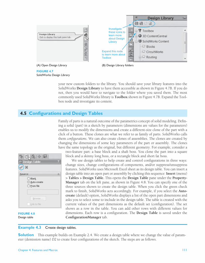
Using library features is easy; you drag a library feature from the design library and drop it onto the open part or assembly. SolidWorks asks you if you want to insert a copy or instance ( derived part ) of the part as shown in Figure 4.6 . If you select Yes , it inserts
the copy in the open part. If you answer No , it opens a blank part and inserts it there.
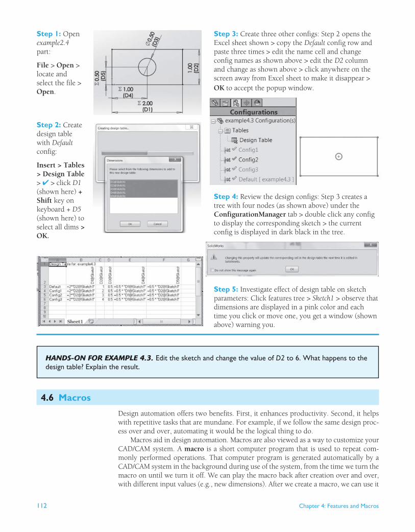
You save library features in a design library. You can organize the library into folders. SolidWorks comes with a Design Library. The path to this library folder is C:\Program Data\SolidWorks\SolidWorks version\design library . (Make sure that hidden files are visible in Windows to see the Program Data folder.) Click the Design Library tab in the SolidWorks Task Pane (shown on the right of the screen) as shown in Figure 4.7A , to open the design library. The library is organized into folders as shown in Figure 4.7B . You can also add
FIGURE 4.6 Using a library feature
Chapter 4: Features and Macros 111
your new custom folders to the library. You should save your library features into the SolidWorks Design Library to have them accessible as shown in Figure 4.7B . If you do not, then you would have to navigate to the folder where you saved them. The most commonly used SolidWorks library is Toolbox shown in Figure 4.7B . Expand the Tool-box node and investigate its content.
4.5 Configurations and Design Tables
Family of parts is a natural outcome of the parametrics concept of solid modeling. Defin-ing a solid (part) in a sketch by parameters (dimensions are values for the parameters) enables us to modify the dimensions and create a different-size clone of the part with a click of a button. These clones are what we refer to as family of parts. SolidWorks calls them configurations . We can also create clones of assemblies. The clones are created by changing the dimensions of some key parameters of the part or assembly. The clones have the same topology as the original, but different geometry. For example, consider a
two-feature part: a base block and a shaft boss. You clone the part into a square block and a skinny long boss, or a rectangle block and short fat boss.
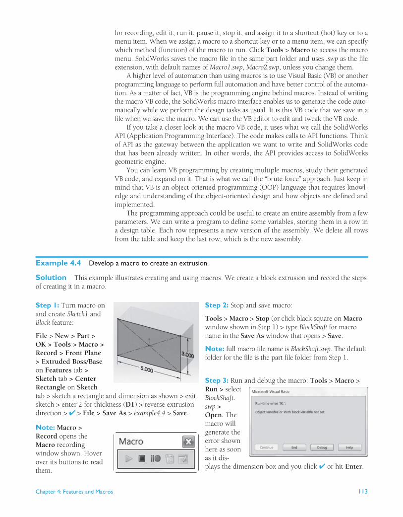
We use design tables to help create and control configurations in three ways: change sizes, change configurations of components, and/or suppress/unsuppress features. SolidWorks uses Microsoft Excel sheet as its design table. You can insert a design table into an open part or assembly by clicking this sequence: Insert (menu) > Tables > Design Table. This opens the Design Table pane under the Property-Manager tab on the left pane, as shown in Figure 4.8 . You can specify one of the three sources shown to create the design table. When you click the green check mark to finish, SolidWorks acts accordingly. For example, if you select the Auto-create (default) option, SolidWorks displays a list of the open part dimensions and asks you to select some to include in the design table. The table is created with the current values of the part dimensions as the default set (configuration). The set shows as a row in the table. You can add other rows with different values for dimensions. Each row is a configuration. The Design Table is saved under the ConfigurationManager tab.
Example 4.3 Create design tables.
Solution This example builds on Example 2.4 . We create a design table where we change the value of param-eter (demission name) D2 to create four configurations of the sketch. The steps are as follows.
Investigatethese icons tolearn moreabout DesignLibrary
Expand this nodeto learn more about Toolbox
(B) Design Library folders
FIGURE 4.7 SolidWorks Design Library
(A) Open Design Library
FIGURE 4.8 Design table
112 Chapter 4: Features and Macros
Step 1: Open example2.4 part:
File > Open > locate and select the file > Open .
Step 2: Create design table with Default config:
Insert > Tables > Design Table > ✔ > click D1 (shown here) + Shift key on keyboard + D5 (shown here) to select all dims > OK.
Step 3: Create three other configs: Step 2 opens the Excel sheet shown > copy the Default config row and paste three times > edit the name cell and change config names as shown above > edit the D2 column and change as shown above > click anywhere on the screen away from Excel sheet to make it disappear > OK to accept the popup window.
Step 4: Review the design configs: Step 3 creates a tree with four nodes (as shown above) under the ConfigurationManager tab > double click any config to display the corresponding sketch > the current config is displayed in dark black in the tree.
Step 5: Investigate effect of design table on sketch parameters: Click features tree > Sketch1 > observe that dimensions are displayed in a pink color and each time you click or move one, you get a window (shown above) warning you.
HANDS-ON FOR EXAMPLE 4.3 . Edit the sketch and change the value of D2 to 6. What happens to the design table? Explain the result.
4.6 Macros
Design automation offers two benefits. First, it enhances productivity. Second, it helps with repetitive tasks that are mundane. For example, if we follow the same design proc-ess over and over, automating it would be the logical thing to do.
Macros aid in design automation. Macros are also viewed as a way to customize your CAD/CAM system. A macro is a short computer program that is used to repeat com-monly performed operations. That computer program is generated automatically by a CAD/CAM system in the background during use of the system, from the time we turn the macro on until we turn it off. We can play the macro back after creation over and over, with different input values (e.g., new dimensions). After we create a macro, we can use it
Chapter 4: Features and Macros 113
for recording, edit it, run it, pause it, stop it, and assign it to a shortcut (hot) key or to a menu item. When we assign a macro to a shortcut key or to a menu item, we can specify which method (function) of the macro to run. Click Tools > Macro to access the macro menu. SolidWorks saves the macro file in the same part folder and uses .swp as the file extension, with default names of Macro1.swp , Macro2.swp , unless you change them.
A higher level of automation than using macros is to use Visual Basic (VB) or another programming language to perform full automation and have better control of the automa-tion. As a matter of fact, VB is the programming engine behind macros. Instead of writing the macro VB code, the SolidWorks macro interface enables us to generate the code auto-matically while we perform the design tasks as usual. It is this VB code that we save in a file when we save the macro. We can use the VB editor to edit and tweak the VB code.
If you take a closer look at the macro VB code, it uses what we call the SolidWorks API (Application Programming Interface). The code makes calls to API functions. Think of API as the gateway between the application we want to write and SolidWorks code that has been already written. In other words, the API provides access to SolidWorks geometric engine.
You can learn VB programming by creating multiple macros, study their generated VB code, and expand on it. That is what we call the “brute force” approach. Just keep in mind that VB is an object-oriented programming (OOP) language that requires knowl-edge and understanding of the object-oriented design and how objects are defined and implemented.
The programming approach could be useful to create an entire assembly from a few parameters. We can write a program to define some variables, storing them in a row in a design table. Each row represents a new version of the assembly. We delete all rows from the table and keep the last row, which is the new assembly.
Example 4.4 Develop a macro to create an extrusion.
Solution This example illustrates creating and using macros. We create a block extrusion and record the steps of creating it in a macro.
Step 1: Turn macro on and create Sketch1 and Block feature: File > New > Part > OK > Tools > Macro > Record > Front Plane > Extruded Boss/Base on Features tab > Sketch tab > Center Rectangle on Sketch tab > sketch a rectangle and dimension as shown > exit sketch > enter 2 for thickness ( D1 ) > reverse extrusion direction > ✔ > File > Save As > example4.4 > Save.
Note: Macro > Record opens the Macro recording window shown. Hover over its buttons to read them.
Step 2: Stop and save macro :
Tools > Macro > Stop (or click black square on Macro window shown in Step 1) > type BlockShaft for macro name in the Save As window that opens > Save .
Note: full macro file name is BlockShaft.swp. The default folder for the file is the part file folder from Step 1.
Step 3: Run and debug the macro: Tools > Macro > Run > select BlockShaft.swp > Open. The macro will generate the error shown here as soon as it dis-plays the dimension box and you click ✔ or hit Enter .
114 Chapter 4: Features and Macros
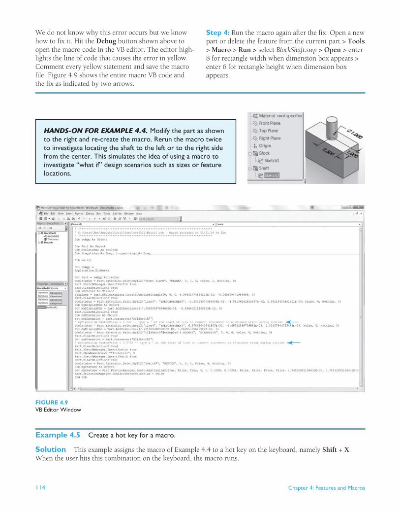
We do not know why this error occurs but we know how to fix it. Hit the Debug button shown above to open the macro code in the VB editor. The editor high-lights the line of code that causes the error in yellow. Comment every yellow statement and save the macro file. Figure 4.9 shows the entire macro VB code and the fix as indicated by two arrows.
Step 4: Run the macro again after the fix: Open a new part or delete the feature from the current part > Tools > Macro > Run > select BlockShaft.swp > Open > enter 8 for rectangle width when dimension box appears > enter 6 for rectangle height when dimension box appears.
HANDS-ON FOR EXAMPLE 4.4 . Modify the part as shown to the right and re-create the macro. Rerun the macro twice to investigate locating the shaft to the left or to the right side from the center. This simulates the idea of using a macro to investigate “what if” design scenarios such as sizes or feature locations.
FIGURE 4.9 VB Editor Window
Example 4.5 Create a hot key for a macro.
Solution This example assigns the macro of Example 4.4 to a hot key on the keyboard, namely Shift + X . When the user hits this combination on the keyboard, the macro runs.

Chapter 4: Features and Macros 115
Step 1: Create macro hot key:
File > Open > locate example4.4 > Open.
Step 2: Locate macro file: Tools > Customize > Keyboard tab > scroll to bottom and locate Macros row > click button in this row to open win-dow shown > click the browse button > locate macro file ( .swp extension) > Open > OK.
Browse button
Click thisbutton to addnew macro
Step 3: Create hot key: Click Shortcut(s) column in Macros row as shown > Shift key + X key to add shortcut as shown below > OK.
Step 4: Use hot key to run macro: Hit Shift + X keys in an open part.
4.7 Tutorials
Tutorial 4–1: Create Sweep Features
A sweep feature requires, at minimum, a profile (cross section) to sweep and a path (curve) to sweep along. We can use a guide curve to control the sweep further. If we do not use a guide curve, the sweep cross section stays constant.
Sweep operations may fail for different reasons. Figure 4.10 shows three of them. As a general rule, the sweep path and guide must intersect the cross section plane, and the cross section must not intersect itself as it traverses the path and/or the guide curve.
(B) Guide curve does not intersect CS plane.
(C) CS intersects itself.
FIGURE 4.10 Some possible sweep operation errors
(A) Path does not intersect CS plane.
116 Chapter 4: Features and Macros
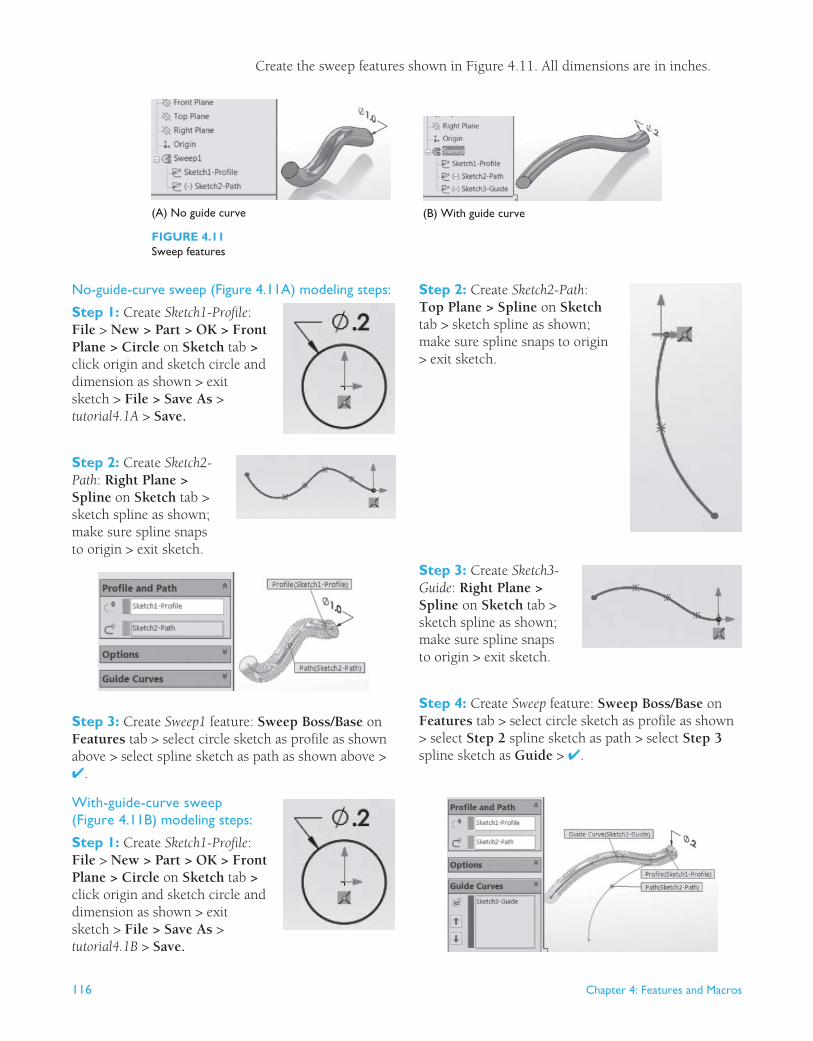
No-guide-curve sweep (Figure 4.11A) modeling steps:
Step 1: Create Sketch1-Profile : File > New > Part > OK > Front Plane > Circle on Sketch tab > click origin and sketch circle and dimension as shown > exit sketch > File > Save As > tutorial4.1A > Save.
Step 2: Create Sketch2-Path : Right Plane > Spline on Sketch tab > sketch spline as shown; make sure spline snaps to origin > exit sketch.
(B) With guide curve
FIGURE 4.11 Sweep features
(A) No guide curve
Create the sweep features shown in Figure 4.11 . All dimensions are in inches.
Step 3: Create Sweep1 feature: Sweep Boss/Base on Features tab > select circle sketch as profile as shown above > select spline sketch as path as shown above > ✔.
With-guide-curve sweep (Figure 4.11B) modeling steps:
Step 1: Create Sketch1-Profile : File > New > Part > OK > Front Plane > Circle on Sketch tab > click origin and sketch circle and dimension as shown > exit sketch > File > Save As > tutorial4.1B > Save.
Step 2: Create Sketch2-Path : Top Plane > Spline on Sketch tab > sketch spline as shown; make sure spline snaps to origin > exit sketch.
Step 3: Create Sketch3-Guide : Right Plane > Spline on Sketch tab > sketch spline as shown; make sure spline snaps to origin > exit sketch.
Step 4: Create Sweep feature: Sweep Boss/Base on Features tab > select circle sketch as profile as shown > select Step 2 spline sketch as path > select Step 3 spline sketch as Guide > ✔.
Chapter 4: Features and Macros 117
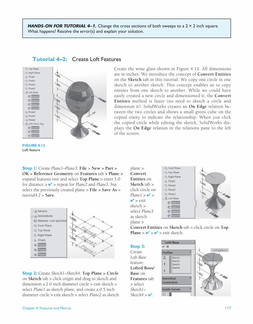
Tutorial 4–2: Create Loft Features
Create the wine glass shown in Figure 4.12 . All dimensions are in inches. We introduce the concept of Convert Entities on the Sketch tab in this tutorial. We copy one circle in one sketch to another sketch. This concept enables us to copy entities from one sketch to another. While we could have easily created a new circle and dimensioned it, the Convert Entities method is faster (no need to sketch a circle and dimension it). SolidWorks creates an On Edge relation be-tween the two circles and shows a small green cube on the copied entity to indicate the relationship. When you click the copied circle while editing the sketch, SolidWorks dis-plays the On Edge relation in the relations pane to the left of the screen.
HANDS-ON FOR TUTORIAL 4–1 . Change the cross sections of both sweeps to a 2 × 2 inch square. What happens? Resolve the error(s) and explain your solution.
FIGURE 4.12 Loft feature
Step 1: Create Plane1–Plane3 : File > New > Part > OK > Reference Geometry on Features tab > Plane > expand features tree and select Top Plane > enter 1.0 for distance > ✔ > repeat for Plane2 and Plane3 , but select the previously created plane > File > Save As > tutorial4.2 > Save .
plane > Convert Entities on Sketch tab > click circle on Plane1 > ✔ > ✔ > exit sketch > select Plane3 as sketch plane > Convert Entities on Sketch tab > click circle on Top Plane > ✔ > ✔ > exit sketch.
Step 3: Create Loft-Base feature: Lofted Boss/Base on Features tab > select Sketch1 – Sketch4 > ✔.
Step 2: Create Sketch1–Sketch4 : Top Plane > Circle on Sketch tab > click origin and drag to sketch and dimension a 2.0 inch diameter circle > exit sketch > select Plane1 as sketch plane, and create a 0.5 inch diameter circle > exit sketch > select Plane2 as sketch

118 Chapter 4: Features and Macros
Step 4: Create Plane4–Plane6 : Reference Geometry on Features tab > Plane > expand features tree and select Plane3 > enter 1.0 for distance > ✔ > repeat for Plane5 and Plane6 , but select the previously created plane.
circle > exit sketch > select Plane5 as sketch plane > Convert Entities on Sketch tab > click Sketch5 just created > ✔ > ✔ > exit sketch > select Plane6 as sketch plane > Convert Entities on Sketch tab > click circle on Plane3 > ✔ > ✔ > exit sketch.
Step 6: Create Loft-Thin1-Top feature: Lofted Boss/Base on Fea-tures tab > select circle of Sketch4, then select Sketch5 – Sketch7 > check Thin Feature box > enter 0.1 for T1 > if needed, click direction box to toggle direction of thickness > ✔. Note: Make sure you select the circle and sketches in a way so that the interpolation points (green circles shown here) line up; otherwise, you twist the loft.
Note: The thickness of the thin feature has a direc-tion: inside or outside the profile. Reverse the direction of the double arrows shown to toggle.
Step 5: Create Sketch5–Sketch7 : Select Plane4 as sketch plane > Circle on Sketch tab > click origin and drag to sketch and dimension a 3.0 inch diameter
HANDS ON FOR TUTORIAL 4–2 . Created a loft using three squares of different sizes as cross sections separated by one inch. The square sizes are 2 × 2, 1 × 1, and 2 × 2 respectively. Create the loft connecting the three sections such that the loft is twisted incorrectly as shown to the right.
Tutorial 4–3: Use the Hole Wizard
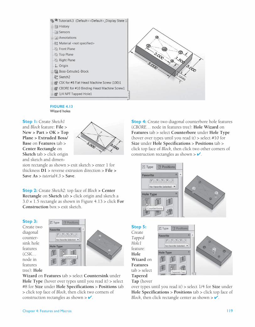
The hole wizard provides two advantages. First, it helps us create standard hole sizes and types, so off-the-shelf bolts will fit perfectly in the holes. Second, it speeds up creating these holes greatly. This tutorial shows how to create sample holes: coun-terbore, countersink, and tapped holes. Figure 4.13 shows these holes. We create an extrusion and add holes to it. We also create Sketch2 on the top face of the Block feature with a center rectangle (construction rectangle) that we use to place holes at its corners.
Chapter 4: Features and Macros 119
Step 1: Create Sketch1 and Block feature: File > New > Part > OK > Top Plane > Extruded Boss/Base on Features tab > Center Rectangle on Sketch tab > click origin and sketch and dimen-sion rectangle as shown > exit sketch > enter 1 for thickness D1 > reverse extrusion direction > File > Save As > tutorial4.3 > Save .
Step 2: Create Sketch2 : top face of Block > Center Rectangle on Sketch tab > click origin and sketch a 3.0 × 1.5 rectangle as shown in Figure 4.13 > click For Construction box > exit sketch.
Step 3: Create two diagonal counter-sink hole features ( CSK… node in features tree): Hole Wizard on Features tab > select Countersink under Hole Type (hover over types until you read it) > select #8 for Size under Hole Specifications > Positions tab > click top face of Block , then click two corners of construction rectangles as shown > ✔.
FIGURE 4.13 Wizard holes
Step 4: Create two diagonal counterbore hole features ( CBORE… node in features tree): Hole Wizard on Features tab > select Counterbore under Hole Type (hover over types until you read it) > select #10 for Size under Hole Specifications > Positions tab > click top face of Block , then click two other corners of construction rectangles as shown > ✔.
Step 5: Create Tapped Hole1 feature: Hole Wizard on Features tab > select Tapered Tap (hover over types until you read it) > select 1/4 for Size under Hole Specifications > Positions tab > click top face of Block , then click rectangle center as shown > ✔.
120 Chapter 4: Features and Macros
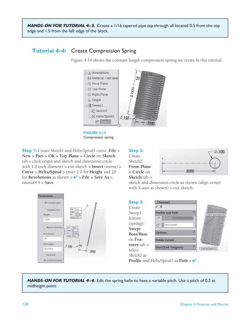
Tutorial 4–4: Create Compression Spring
Figure 4.14 shows the constant length compression spring we create in this tutorial.
HANDS-ON FOR TUTORIAL 4–3 . Create a 1/16 tapered pipe tap through all located 0.5 from the top edge and 1.5 from the left edge of the block.
FIGURE 4.14 Compression spring
Step 1: Create Sketch1 and Helix/Spiral1 curve: File > New > Part > OK > Top Plane > Circle on Sketch tab > click origin and sketch and dimension circle with 1.0 inch diameter > exit sketch > Insert (menu) > Curve > Helix/Spiral > enter 2.0 for Height and 20 for Revolutions as shown > ✔ > File > Save As > tutorial4.4 > Save .
Step 2: Create Sketch2 : Front Plane > Circle on Sketch tab > sketch and dimension circle as shown (align center with X-axis as shown) > exit sketch.
Step 3: Create Sweep1 feature (spring): Swept Boss/Base on Fea-tures tab > select Sketch2 as Profile and Helix/Spiral1 as Path > ✔.
HANDS-ON FOR TUTORIAL 4–4 . Edit the spring helix to have a variable pitch. Use a pitch of 0.2 at midheight point.
Chapter 4: Features and Macros 121
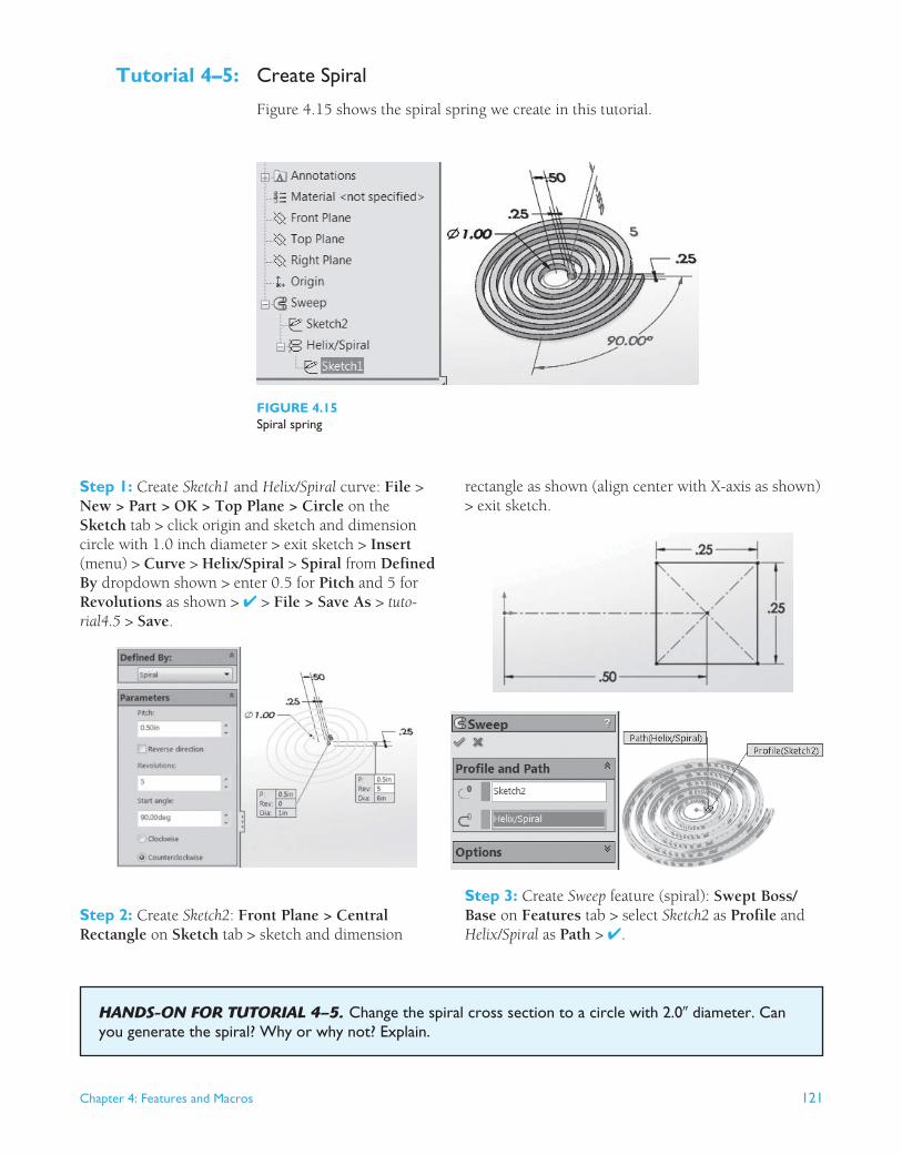
Tutorial 4–5: Create Spiral
Figure 4.15 shows the spiral spring we create in this tutorial.
FIGURE 4.15 Spiral spring
Step 1: Create Sketch1 and Helix/Spiral curve: File > New > Part > OK > Top Plane > Circle on the Sketch tab > click origin and sketch and dimension circle with 1.0 inch diameter > exit sketch > Insert (menu) > Curve > Helix/Spiral > Spiral from Defined By dropdown shown > enter 0.5 for Pitch and 5 for Revolutions as shown > ✔ > File > Save As > tuto-rial4.5 > Save .
rectangle as shown (align center with X-axis as shown) > exit sketch.
Step 3: Create Sweep feature (spiral): Swept Boss/Base on Features tab > select Sketch2 as Profile and Helix/Spiral as Path > ✔.
Step 2: Create Sketch2 : Front Plane > Central Rectangle on Sketch tab > sketch and dimension
HANDS-ON FOR TUTORIAL 4–5. Change the spiral cross section to a circle with 2.0� diameter. Can you generate the spiral? Why or why not? Explain.

122 Chapter 4: Features and Macros
Tutorial 4–6: Create Features
This tutorial covers the creation of these features: chamfer, fillet, slot, shell, draft, and rib. All dimensions are inches. Here are useful observations:
1. Make sure to pay attention to the visual clues shown in the left pane while creating these features.
2. For example, the box symbol under Chamfer parameters indicates that you can chamfer a face, an edge, or a vertex (corner point). As expected, chamfering a face chamfers all its edges. Chamfering a corner chamfers the three edges that meet there.
3. A rib requires a profile sketch (e.g., a line or stepwise line) and a thickness.
Step 1: Create Sketch1 and Block feature: File > New > Part > OK > Top Plane > Extruded Boss/Base on Features tab > Center Rectangle on Sketch tab > click origin and sketch and dimension as shown > exit sketch > reverse extrusion direction > enter 0.5 for thickness D1 > ✔ > File > Save As > tutorial4.6 > Save.
Step 2: Chamfer an edge of Block feature: Fillet dropdown on Features tab > Chamfer > select Block edge shown > use 0.1 for D and 45 degrees for angle > ✔.
Step 3: Fillet an edge of Block feature: Fillet on Features tab > select Block edge shown > use 0.1 for fillet radius > ✔.
Step 4: Create a straight slot in Block feature: Select Block top face as a sketch plane > Extruded Cut on Features tab > Straight Slot on Sketch tab > sketch and dimen-sion slot as shown > exit sketch > Through All > ✔.
Step 5: Shell Block feature: Shell on Fea-tures tab > select top face of Block > enter 0.1 for wall thickness D1 > ✔.
Step 6: Draft Block feature: Delete the chamfer, fillet, and shell features > Draft on Features tab > enter 10 degrees for Draft Angle > select top face of Block as Neutral Plane > select Block four side faces to draft > ✔.
Step 7: Create a rib feature: Delete the slot and draft features > select front face of Block > Extruded Boss/Base on Features tab > Rectangle on Sketch tab > sketch and dimension rectangle as shown above > exit sketch > reverse extrusion direction > enter 3.0 for thickness D1 > ✔ > Front Plane > Rib on Features tab > Line on Sketch tab > sketch a line using the midpoints of the two edges as shown above > exit sketch > enter 0.5 for thickness T1 > ✔.
Chapter 4: Features and Macros 123
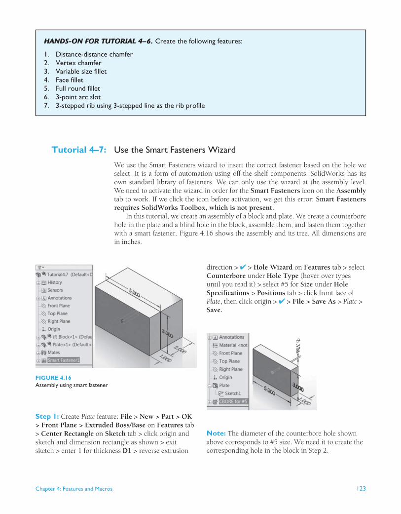
Tutorial 4–7: Use the Smart Fasteners Wizard
We use the Smart Fasteners wizard to insert the correct fastener based on the hole we select. It is a form of automation using off-the-shelf components. SolidWorks has its own standard library of fasteners. We can only use the wizard at the assembly level. We need to activate the wizard in order for the Smart Fasteners icon on the Assembly tab to work. If we click the icon before activation, we get this error: Smart Fasteners requires SolidWorks Toolbox, which is not present.
In this tutorial, we create an assembly of a block and plate. We create a counterbore hole in the plate and a blind hole in the block, assemble them, and fasten them together with a smart fastener. Figure 4.16 shows the assembly and its tree. All dimensions are in inches.
HANDS-ON FOR TUTORIAL 4–6 . Create the following features:
1. Distance-distance chamfer 2. Vertex chamfer 3. Variable size fillet 4. Face fillet 5. Full round fillet 6. 3-point arc slot 7. 3-stepped rib using 3-stepped line as the rib profile
FIGURE 4.16 Assembly using smart fastener
Step 1: Create Plate feature: File > New > Part > OK > Front Plane > Extruded Boss/Base on Features tab > Center Rectangle on Sketch tab > click origin and sketch and dimension rectangle as shown > exit sketch > enter 1 for thickness D1 > reverse extrusion
Note: The diameter of the counterbore hole shown above corresponds to #5 size. We need it to create the corresponding hole in the block in Step 2.
direction > ✔ > Hole Wizard on Features tab > select Counterbore under Hole Type (hover over types until you read it) > select #5 for Size under Hole Specifications > Positions tab > click front face of Plate , then click origin > ✔ > File > Save As > Plate > Save.

124 Chapter 4: Features and Macros
Step 2: Create Block feature: File > New > Part > OK > Front Plane > Extruded Boss/Base on Features tab > Center Rectangle on Sketch tab > click origin and sketch and dimension rectangle as shown > exit sketch > enter 2 for thickness D1 > reverse extrusion direc-tion > ✔ > front face of Block > Extruded Cut on Features tab > Circle on Sketch tab > click origin and sketch and dimension as shown > exit sketch > enter 1 for thickness D1 > ✔ > File > Save As > Block > Save .
Assembly tab > Coincident > select the correspond-ing top edges of Block and Plate > ✔ > select the corresponding right edges of Block and Plate > ✔ > ✔.
Step 4: Activate Smart Fasteners wizard: Tools > Add-Ins > SolidWorks Toolbox Browser > OK . This adds the Toolbox menu to the menu bar to the right of the Tools menu. You may deactivate the Toolbox by using the same sequence but unchecking the Toolbox Browser from the Add-Ins window.
Step 5: Add a fastener: Smart Fasteners on Assembly tab > OK (to accept that it may take extra time) > expand features tree > expand Plate instance tree node > select CBORE for #5 node > Add > ✔.
Step 3: Create assembly: File > New > Assembly > OK > Browse > locate Block and Plate parts > select Block + Ctrl + Plate > Open > click ✔ to place Block instance in assembly origin > click anywhere in graphics pane to place Plate instance > Mate on
HANDS-ON FOR TUTORIAL 4–7 . Modify Block and Plate parts to create four corner countersink holes. Re-create the assembly and use four smart fasteners.
Tutorial 4–8: Create a Bolt
Bolts, like gears, are an important and essential mechanical element. While bolts are standard off-the-shelf components, this tutorial shows how to create the CAD model of one due to its learning value. Figure 4.17 shows the bolt and its features tree. All dimen-sions are in inches.
FIGURE 4.17 A bolt
Chapter 4: Features and Macros 125
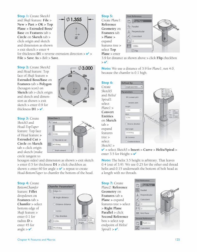
Step 1: Create Sketch1 and Shaft feature: File > New > Part > OK > Top Plane > Extruded Boss/Base on Features tab > Circle on Sketch tab > click origin and sketch and dimension as shown > exit sketch > enter 4 for thickness D1 > reverse extrusion direction > ✔ > File > Save As > Bolt > Save .
Step 2: Create Sketch2 and Head feature: Top face of Shaft feature > Extruded Boss/Base on Features tab > Polygon (hexagon icon) on Sketch tab > click origin and sketch and dimen-sion as shown > exit sketch > enter 0.9 for thickness D1 > ✔.
Step 3: Create Sketch3 and Head-TopTaper feature: Top face of Head feature > Extruded Cut > Circle on Sketch tab > click origin and sketch (make circle tangent to hexagon sides) and dimension as shown > exit sketch > enter 0.5 for thickness D1 > click checkbox as shown > enter 60 for angle > ✔ > repeat to create Head-BottomTaper to chamfer the bottom of the head.
Step 4: Create BottomChamfer feature: Fillet dropdown on Features tab > Chamfer > select bottom edge of Shaft feature > enter 0.1 for radius D > enter 45 for angle > ✔.
Step 5: Create Plane1 : Reference Geometry on Features tab > Plane > expand features tree > select Top Plane > enter 3.9 for distance as shown above > click Flip checkbox > ✔. Note: We use a distance of 3.9 for Plane1 , not 4.0, because the chamfer is 0.1 high.
Step 6: Create Sketch5 and Helix/Spiral1 : select Plane1 > Convert Entities on Sketch tab > expand features tree > select Sketch1 > ✔ > select Sketch5 > Insert > Curve > Helix/Spiral > enter 3.5 for Height > ✔ Note: The helix 3.5 height is arbitrary. That leaves 0.4 (out of 3.9). We use 0.25 for the other end thread helix and 0.15 underneath the bottom of bolt head as a length with no threads.
Step 7: Create Plane2 : Reference Geometry on Features tab > Plane > expand features tree > select > Right Plane Parallel > click Second Reference box > select top endpoint of Helix/Spiral1 > ✔.

126 Chapter 4: Features and Macros
Step 8: Create Sketch6 and Cut-Sweep1-Thread feature: Plane2 > Swept Cut on Features tab > Polygon (hexagon icon) on Sketch tab > click near end of helix and sketch and dimension as shown > exit sketch > select Sketch6 as profile and Helix/Spiral1 as path > ✔.
Step 9: Create Plane3 : Reference Geometry on Features tab > Plane > expand features tree > select > Top Plane Parallel > click Second Reference box > select top endpoint of Helix/Spiral1 > ✔.
Step 10: Create Sketch7 and Helix/Spiral2 : Select Plane3 > Convert Entities on Sketch tab > expand features tree > select Sketch1 > ✔ > select Sketch7 > Insert > Curve > Helix/Spiral > enter 0.25 for Height > click Taper Helix check-box > enter 30 for angle > click Taper outward checkbox > ✔.
Step 11: Create Cut-SweepEndThread feature: Swept Cut on Features tab > select Sketch6 as profile and Helix/Spiral2 as path > ✔.