steering microtubule shuttle transport with dynamically ...soory/pdf/mahajannanoscale2016.pdf ·...
TRANSCRIPT

Nanoscale
PAPER
Cite this: Nanoscale, 2016, 8, 8641
Received 1st December 2015,Accepted 22nd March 2016
DOI: 10.1039/c5nr08529b
www.rsc.org/nanoscale
Steering microtubule shuttle transport withdynamically controlled magnetic fields†
K. D. Mahajan,‡a G. Ruan,‡a,b C. J. Dorcéna,a G. Vieira,c G. Nabar,a N. F. Bouxsein,d
J. J. Chalmers,a G. D. Bachand,d R. Sooryakumarc and J. O. Winter*a,e
Nanoscale control of matter is critical to the design of integrated nanosystems. Here, we describe a
method to dynamically control directionality of microtubule (MT) motion using programmable magnetic
fields. MTs are combined with magnetic quantum dots (i.e., MagDots) that are manipulated by external
magnetic fields provided by magnetic nanowires. MT shuttles thus undergo both ATP-driven and exter-
nally-directed motion with a fluorescence component that permits simultaneous visualization of shuttle
motion. This technology is used to alter the trajectory of MTs in motion and to pin MT motion. Such an
approach could be used to evaluate the MT–kinesin transport system and could serve as the basis for
improved lab-on-a-chip technologies based on MT transport.
Introduction
Transport at the nanoscale requires overcoming challengesunique to the length scale, including Brownian motion, lowReynolds number conditions, and difficulty in directly inter-facing with and manipulating structures.1 In living organisms,such transport is achieved, at least in part, by a group ofenzymes known as motor proteins that dissipate chemicalenergy for the active translocation of biomolecular constitu-ents and organelles within the cytoplasm. Because of theircentral role in cellular transport, motor proteins have beenbroadly studied as a model system for achieving nanofluidictransport in synthetic and hybrid systems.2 In particular, theintracellular transport system composed of kinesin motorsand microtubule (MT) filaments has been used for the activeassembly of composite nanomaterials,3–6 as well as the deve-lopment of hybrid “smart dust” sensors.7–9
Kinesin motor proteins consist of two heads that hydrolyzeadenosine triphosphate (ATP) and propagate processively via ahand-over-hand motion along tracks formed by ∼25 nm dia-
meter MTs. Researchers have investigated several ex vivomethods to control kinesin motion, or in the inverted motilityassay, MT motion on kinesin-coated surfaces. For example, theavailability of fuel may be controlled using light or pH, and inturn regulate kinesin motion.10,11 Motion can also be inhibitedby the binding of small molecules to selected regions of thekinesin molecule12–14 or by rendering a kinesin-coated surfaceunable to bind MTs (i.e., through electrostatics or steric hin-drance).15,16 All of these strategies, however, have focused onthe initiation or suppression of motion, and not control of thevector of motion.
Control of ex vivo transport vectors has primarily relied onphysical11,17,18 or chemical19 patterns to direct MT motion onkinesin-coated surfaces (i.e., the inverted motility assay).However, the majority of these approaches require lithographicpatterning and permit no dynamic control over the resultingvectors, which generally limits the MT trajectories to those ofthe original pattern. Further, MTs can escape physical orchemical barriers, leading to stalling or undesired motion.20
MTs have demonstrated the capability of traversing physicalbarriers as much as 40 times their height (e.g., up to 1 µm(ref. 11)). None of these approaches permit dynamic alterationof the trajectory of a MT in motion.
Apart from patterning approaches, control of MT vectorscan be achieved by external fields, such as fluid flow,21,22 elec-trical,23,24 and magnetic25–27 fields. Fluid flow has been usedto align MTs in a specific orientation and to enable uni-direc-tional transport of kinesin and associated cargoes in a pre-selected direction.21,22 More promising approaches towarddynamic vector regulation involve the use of external fieldswith the capability of investigator control. For example, Dekkeret al. showed that MT trajectory could be altered by electro-
†Electronic supplementary information (ESI) available. See DOI: 10.1039/c5nr08529b‡These authors contributed equally.
aWilliam G. Lowrie Department of Chemical and Biomolecular Engineering,
151 West Woodruff Avenue; The Ohio State University, Columbus, OH 43210, USAbDepartment of Biomedical Engineering, College of Engineering and Applied
Sciences, Nanjing University, Nanjing, 200697, ChinacDepartment of Physics, The Ohio State University, Columbus, OH 43210, USAdCenter for Integrated Nanotechnologies, Sandia National Laboratories,
Albuquerque, NM 87185, USAeDepartment of Biomedical Engineering, The Ohio State University, Columbus,
OH 43210, USA. E-mail: [email protected]
This journal is © The Royal Society of Chemistry 2016 Nanoscale, 2016, 8, 8641–8649 | 8641
Publ
ishe
d on
23
Mar
ch 2
016.
Dow
nloa
ded
by O
HIO
ST
AT
E U
NIV
ER
SIT
Y o
n 06
/07/
2016
17:
15:0
1.
View Article OnlineView Journal | View Issue
phoretic motion in an external electric field.24 In the invertedmotility assay, MT motion is directed by Brownian motion atthe MT tip as it progresses from motor to motor. By applyingan electric field to a charged tip, the trajectory of a MT can bealtered proportional to the force applied and the bendingradius of the MT.28 Inspired by this work, we investigated thepotential of magnetic fields to dynamically alter MT motion.
Magnetic fields are particularly attractive for MT vectorcontrol because they can deliver programmable fields tospecific micro-regions without the need for repeated litho-graphy. Magnetic fields have been used to align MTs alongmagnetic field lines,29 similar to flow-based approaches,21,22
and to direct MT binding to a surface,27 similar to electrophor-etic methods;23 thus, combining best attributes of severalalignment and steering methods. Further, proof of concept fordynamic alteration of MT trajectory has been demonstrated.26
Hutchins et al. showed that CoFe2O4 magnetic nanoparticlesattached to the leading edge of MTs may be used to alter theirmotion in the presence of a simple NdFeB cube magnet. Inthat work, altering MT trajectories was achieved by varying theseparation distance between the magnet and the MTs to regu-late the magnetic field strength, but with little opportunity forfinely tuned, dynamic control.
Here, we examine dynamic alteration of MT motion in situusing programmable, micro-patterned magnetic fields. Thesefields can be tuned via joystick or voice commands to preciselymanipulate objects ranging from ∼10 nm to microns in size,including micro- and nano-particles and magnetically-labelledcells and molecules.30–32 The two dimensionality of the arrayof microscopic patterns also enables easy platform integrationwith microfluidic channels and allows for single-focal plane,real time observation of individual or multiple living organ-isms. This manipulation set-up thus offers far more accurateselection than data averaging over a population of MT shuttles.
To render MTs gliding on a kinesin surface responsive tomagnetic field gradients, MTs were combined with magneticquantum dot (i.e., MagDot) cargoes. The MagDot cargoesconsist of micelles containing (1) superparamagnetic ironoxide nanoparticle (SPION) constituents that permit control ofmotion and (2) fluorescent quantum dot (QD) componentsthat permit quantification through real-time optical characteri-zation. This approach thus provides specific directionalcontrol, can potentially process multiple molecules in parallel,and integrates optical tracking with dynamic movement viathe fluorescent MagDot element, permitting real time obser-vation of MT shuttles.
Results and discussionMagDot-labelled microtubules
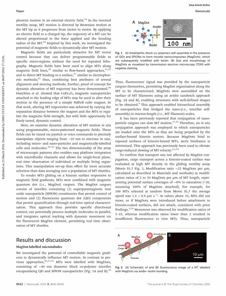
We investigated the potential of controllable magnetic gradi-ents to dynamically influence MT motion. In contrast to pre-vious approaches,26,27,33 MTs were labelled with MagDots,consisting of ∼40 nm diameter block co-polymer micellesencapsulating QD and SPION nanoparticles (Fig. 1A and B).30
Thus, fluorescence signal was provided by the nanoparticlecargoes themselves, permitting MagDot organization along theMT to be characterized. MagDots were assembled on thesurface of MT filaments using an avidin sandwich approach(Fig. 2A and B), enabling structures with well-defined shapesto be obtained.4 This approach enabled hierarchical assemblyof nanoparticles that bridged the nano-(i.e., micellar self-assembly) to micron-length (i.e., MT filament) scales.
It has been previously reported that conjugation of nano-particle cargoes can slow MT motion.27,34 Therefore, an in situconjugation approach was employed in which nanoparticlesare loaded onto the MTs as they are being propelled by thesurface-bound kinesin motors. Because MagDots bind toexposed surfaces of kinesin-bound MTs, steric hindrance isminimized. This approach has previously been used to obviatecargo-induced slowing of MT velocity.4,5,34
To confirm that transport was not affected by MagDot con-jugation, cargo transport across a kinesin-coated surface wasevaluated at high MT density in the gliding motility assay(Movie S1,† Fig. 3, Modification ratio ∼23 MagDots per µm,calculated as described in Materials and methods) at modifi-cation ratios of 2 to 50 MagDots per µm of MT length, repre-senting potential surface coverages of ∼8% to saturation (>20,assuming 100% of MagDots attached). For example, for100 MTs selected at random from Movie S1,† the averagespeed was 1.4 ± 0.9 µm s−1. At values above 25, MTs did notmove, or if MagDots were introduced before attachment tokinesin-coated surfaces, did not attach, consistent with priorfindings.3,34 Movement was observed for modification ratios of5–25, whereas modification ratios lower than 2 resulted ininsufficient fluorescence to view MTs. Thus, nanoparticle
Fig. 1 (A) Amphiphilic block co-polymers self-assemble in the presenceof QDs and SPIONs to form micelle nanocomposites (MagDots), whichare subsequently modified with biotin. (B) Size and morphology ofMagDots as visualized by transmission electron microscopy (TEM) withnegative staining.
Fig. 2 (A) Schematic of and (B) fluorescence image of a MT labelledwith MagDots via avidin–biotin bonding.
Paper Nanoscale
8642 | Nanoscale, 2016, 8, 8641–8649 This journal is © The Royal Society of Chemistry 2016
Publ
ishe
d on
23
Mar
ch 2
016.
Dow
nloa
ded
by O
HIO
ST
AT
E U
NIV
ER
SIT
Y o
n 06
/07/
2016
17:
15:0
1.
View Article Online

modification could diminish MT movement as saturation wasapproached, but did not appear to provide noticeable impedi-ment to MT transport via ATP-mediated mechanisms at lowerconcentrations.
We also evaluated the types of motion evidenced by MTs inMovie S1,† including the average change in angle as a functionof time (Δθ̄) (geometry shown in ESI Fig. 1†). In the absence ofmagnetic fields, Brownian motion at the tip dictates MT trajec-tory. Thus, Gaussian behaviour would be expected. As antici-pated, we observed both straight (83%) and bent (17%) MTtrajectories, and Δθ̄ was a Gaussian centred at 0.06° with a stan-dard deviation of 2.52° (Fig. 4). The probability of bending isinfluenced by Brownian motion, but is also a function of MTlength (average MT length for Movie S1 is shown in ESI Fig. 2†).
Microtubule deflection and capture in dynamic magneticfields
Control of the MT motion was achieved using tunable mag-netic traps located at vertices of nanoscale zigzag cobalt–ironwires patterned onto a silicon chip. Strong magnetic field gra-dients near wire vertices attract constituent MagDots; andtherefore, are capable of guiding MT motion toward the wirevertices. An external, out-of-plane magnetic field canstrengthen the attractive magnetic force, whereas reversing thedirection of this out-of-plane field weakens the attractive forceor makes it weakly repulsive (Fig. 5). A zig-zag micro-patternedmagnetic nanowire platform was used to modify the directionof MTs undergoing ATP-driven, biological motion (Fig. 6 and7, Movies S2–S4†) by using magnetic forces to pull MTs towardwire vertices. In addition, by modifying external magneticfields, the force pulling the MTs could be modified, removed,or reversed, thus, permitting dynamic, investigator control of
Fig. 3 Transport of MTs on kinesin-coated surfaces through ATP-drivenmotion, demonstrating that transport of MagDots does not significan1tlyimpede MT–kinesin interactions. Two types of motion are highlightedwith circles. The MT circled in white undergoes linear motion throughthe frames, whereas the MT circled in black exhibits circular or curvedmotion.
Fig. 4 Histogram of the average change in theta (Δθ̄, degrees) as afunction of time in the absence of a magnetic field, obtained from ana-lysis of 100 random MTs in Movie S1.† Δθ̄ is a Gaussian centred at 0.06°with a standard deviation of 2.52°, indicating the role of Brownianmotion in MT steering in the absence of fields.
Fig. 5 Illustration of trapping forces (blue arrows) for wires in different applied field configurations. (A) A zig-zag wire with magnetization profiledefined by the white arrows. In the presence of a downward out-of-plane applied field (Hz), vertices on the left side of the wire attract magnetic par-ticles, while vertices on the right side are weakly repulsive. (B) Upon switching the out-of-plane field, these attributes are reversed. (C) Calculationsare shown for the lateral magnetic trapping forces (Fr) on a ∼50 nm-diameter MagDot to the right of a vertex, as indicated by the dotted line in (B).Forces are calculated for a MagDot with a center 50–150 nm above the plane of the wires (z direction). Fr falls quickly with increased distance fromvertex (r
*
). The trapping force (1) at an r*
of 0.125 µm is estimated to be about 50 times larger than the trapping force (2) at an r*
of 0.5 µm. The lateraltrapping force drops to zero at the trap centre.
Nanoscale Paper
This journal is © The Royal Society of Chemistry 2016 Nanoscale, 2016, 8, 8641–8649 | 8643
Publ
ishe
d on
23
Mar
ch 2
016.
Dow
nloa
ded
by O
HIO
ST
AT
E U
NIV
ER
SIT
Y o
n 06
/07/
2016
17:
15:0
1.
View Article Online
the timing and directionality of motion. In contrast, MTshuttle systems based on biological or biomimeticapproaches11 provide limited control over directionality.
We first evaluated the ability to modify trajectory as a func-tion of MagDot modification ratio. Consistent with controlexperiments (Movie S1†), increased MagDot modification ratio
was correlated with decreases in MT speed (Table 1) (i.e., 2.8,2.3, and 1.1 µm s−1 for modification ratios of 13, 20, and 23MagDots per µm MT length, respectively). MTs did notappreciably respond to the patterned magnet vertices at modi-fication ratios below 10 MagDots per µm.
Additionally, we observed that the ability to manipulate MTtrajectory was dependent on MT length. MTs >15–20 µm didnot respond to the magnetic gradients employed in thissystem. Bending energy is related to MT length, L, via EBend =kBTLpL/2R
2, where kB is Boltzmann’s constant, T is tempera-ture, Lp is the MT persistence length, R is the MT radius of cur-vature, so longer MTs may be more difficult to bend and steer.In particular, whereas the persistence length of MTs hasreported to be 1–10 mm,35 it has also been shown that the per-sistence length is inversely correlated to the contour length.36
Thus, the inability to effectively guide long MTs with magneticfields may be related to an increase in their persistence lengthand the required energy to bend and steer them. To this point,significantly straighter trajectories in the gliding motility assayhave been reported when the persistence length of MTs isincreased by the addition of divalent metal ions.37 Moreover,the persistence length of short MTs (2–3 microns) has beenshown to be significantly reduced (i.e., Lp of a few hundredmicrons),36 and thus would require considerably less energy tobend and steer them with magnetic fields. The MTs observedin Movies S2–4† were short: 2.9, 2.0, and 2.7 µm, respectively.
We observed two MT behaviours resulting from modifyingthe trajectories of a mobile MT using engineered magnetic
Fig. 6 MT shuttle trajectories altered by applied magnetic force. (A) Themicroassembly moves in a linear fashion, then, under the influence ofthe magnetic trap, is deflected and changes direction near consecutiverightward-facing vertices, continuing in a linear manner after leaving thevicinity of the vertex. In this case, the magnetic trap is not strongenough to fully capture the MT. (B) When the magnetic trap is 1capableof fully capturing the MT, the microassembly undergoes circular motionand is contorted into a circular shape.
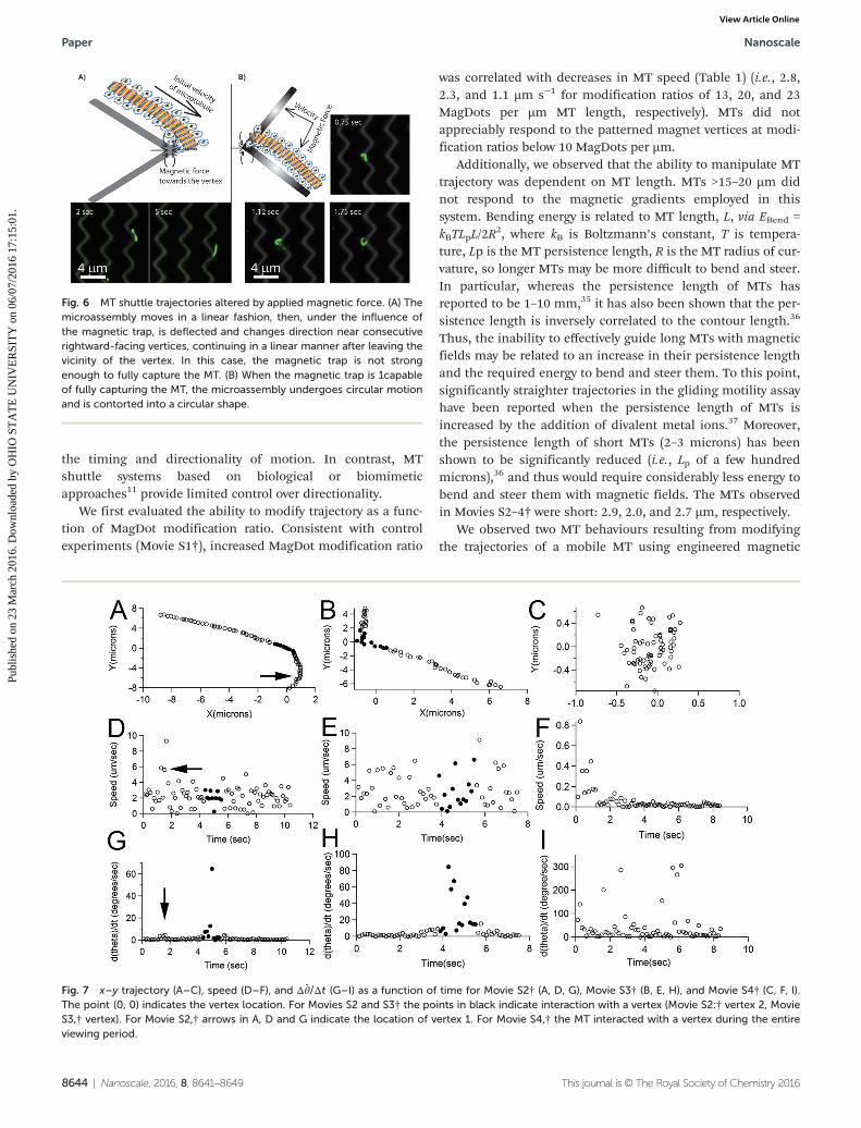
Fig. 7 x–y trajectory (A–C), speed (D–F), and Δθ̄/Δt (G–I) as a function of time for Movie S2† (A, D, G), Movie S3† (B, E, H), and Movie S4† (C, F, I).The point (0, 0) indicates the vertex location. For Movies S2 and S3† the points in black indicate interaction with a vertex (Movie S2:† vertex 2, MovieS3,† vertex). For Movie S2,† arrows in A, D and G indicate the location of vertex 1. For Movie S4,† the MT interacted with a vertex during the entireviewing period.
Paper Nanoscale
8644 | Nanoscale, 2016, 8, 8641–8649 This journal is © The Royal Society of Chemistry 2016
Publ
ishe
d on
23
Mar
ch 2
016.
Dow
nloa
ded
by O
HIO
ST
AT
E U
NIV
ER
SIT
Y o
n 06
/07/
2016
17:
15:0
1.
View Article Online

fields. First, upon passing nearby a vertex, a MT can deflect itsmotion briefly toward the vertex and continue in a straight tra-jectory, analogous to the unbound hyperbolic motion of a pro-jectile attracted to a central potential (Fig. 6A, Fig. 7A and B,Movie S2 and S3,† Modification ratios: 20 MagDots per µm, 13MagDots per µm, respectively). The magnetic field varies as afunction of distance from each vertex (Fig. 5C); and based onanalysis of the MT trajectories (Fig. 7, Table 1), includingspeed and change in angle (Δθ̄) as a function of time, weobserve magnetic steering of MTs when the distance from thevertex (~r) is <∼1.5 µm.
To demonstrate investigator control of magnetic deflection,the external magnetic field was reversed, turning off the trap,at 8 and 5 s in Movie S2 and S3,† respectively (frame 64 and40, respectively). Thus, in Movie S2,† the MT is initiallymoving in a linear trajectory, and encounters 2 vertices beforethe field is reversed. In both cases, θ changes rapidly in thevicinity of the vertex compared to changes at distances>1.5 µm from vertex or without applied magnetic field (Fig. 7A,D and G; Table 1). The average speed nearly doubled nearvertex 1, but was ∼6% lower near vertex 2, possibly indicatingthe effect of repulsive and attractive vertices, respectively. Simi-larly in Movie S3,† θ changes dramatically near the vertex, andspeed is reduced by ∼8% (Fig. 7B, E and H). In the absence ofa field or when~r exceeds 1.5 µm, the MT continues in a rela-tively straight trajectory with little Δθ̄ because the magneticforce is sufficiently weak.
In Movies S2 and S3,† two types of deflection responses areobserved. When the MT entered the vertex parallel to the firstvertex arm (ϕentry ∼ 0°) then the MT exited the vertex roughlyperpendicular to the vertex tip (ϕexit ∼ 39°). When the MTentered the vertex roughly perpendicular to the vertex tip(ϕentry ∼ 39°), then the MT was attracted to the second vertexarm, exiting parallel to it (ϕexit ∼ 78°). These results clearlyindicate that magnetic fields can alter MT trajectories in aninvestigator controlled manner.
Second, we also observed that, on rare occasions, MTswhich pass close enough to a wire vertex (~r , 0:5 μm) arecapable of being confined to the vicinity of a wire vertex,induced to form an approximately circular shape, and made tomove in an approximately circular motion near the vertex(Fig. 6B, Fig. 7C, F and I; Movie S4,† Modification ratio: 23MagDots per µm). The latter behaviour requires that MT be
sufficiently close to the trap; the trap must be attractive ratherthan repulsive; and, the kinesin motor propulsion force mustbe sufficiently low that the trap force can overcome linearmotion. The angular trap force is a function of~r and MagDotlabelling. The lateral angular trapping force rises dramaticallywith MT proximity to the vertex (~r), as our calculations indicate(Fig. 5C). For example, we estimate that as the MT approachesthe vertex, the attractive force on a 50 nm SPION located150 nm above the trap surface increases by about 50 fold as itmoves from an r
*of 0.5 to 0.125 µm (position 2 to 1, Fig. 5B
and C) from the vertex. Therefore, if the angular trap force ishigh, the ATP-mediated MT propulsion will be insufficient toescape the magnetic trap. In this case, the leading tip of theMT becomes pinned by the magnetic field, and the force ofthe motors pushing on the MT initiates bending of the MTinto a circular shape resulting in circular motion. To the bestof our knowledge, this is the first report in which a kinesin-translocated MT is deliberately pinned,4,24,38 which suggeststhe potential use of magnetic force to temporarily “pause”transport. By reversing the magnetic field, we could potentiallyun-pin the MT. Such a feature suggests that engineeredmagnetic fields could also be exploited to create MTs withnew shapes, beyond those achievable through typicalmanipulations.
Forces applied to MTs by magnetic nanowire traps
Although some MTs were observed to bend in the absence ofmagnetic fields (Movie S1†), the radius of curvature observedin MTs exposed to engineered magnetic fields can be substan-tially smaller than that observed in the absence of magneticforces (i.e., ∼0.5 µm vs. 2–12 µm, Table 2). The bending energy(EBend) was calculated for each of the 3 MTs with the greatestdegree of curvature in Movie S1,† and these were found to be1–2 orders of magnitude lower than the energy that couldreasonably be provided by the motors (EMotors), suggesting thatthe kinesin motors are responsible for the observed bending(Table 2, see ESI† for all calculations).
To confirm the role of magnetic fields in inducing bendingin Movies S2–4,† EBend was calculated for each MT. In MoviesS2 and S3,† no pinning behaviour is observed and EBend is lessthan EMotors, indicating that the magnetic force is insufficientto overcome the force provided by the kinesin motors, whichcould have potentially resulted in MT pinning. However, in
Table 1 Average nanoparticle loading (NPs per µm), MT speed (v̄), change in angle with respect to the x-axis (Δθ̄), and angles of entry and exit withrespect to the vertex (ϕ) with and without a magnetic field. (See ESI Fig. 1 for geometry employed). Field is defined as active for MTs within 1.5 µm ofa vertex (vertex). No field was defined as points more than 1.5 µm distant from a vertex, or points after the field was removed (no vertex)
MT NPs/µm Frames v̄ (µm s−1) Δθ̄ (°) ϕentry (°) ϕexit (°)
Movie 1, (control) ∼23 All 1.4 0.06 N/A N/AMovie 2, vertex 1 20 9–14 4.5 2.30 7.7 25.6Movie 2, vertex 2 20 36–45 2.1 10.4 50.2 78.3Movie 2, no vertex 20 1–8, 15–33, 45–84 2.3 0.89 N/A N/AMovie 3, vertex 13 32–45 2.5 28.3 0 39.3Movie 3, no vertex 13 1–31, 45–61 2.8 2.62 N/A N/AMovie 4, vertex 23 All 1.1 42.4 0 0
Nanoscale Paper
This journal is © The Royal Society of Chemistry 2016 Nanoscale, 2016, 8, 8641–8649 | 8645
Publ
ishe
d on
23
Mar
ch 2
016.
Dow
nloa
ded
by O
HIO
ST
AT
E U
NIV
ER
SIT
Y o
n 06
/07/
2016
17:
15:0
1.
View Article Online

Movie S4,† EBend is 78.7 × 10⁻¹⁸ J vs. 21.2 × 10⁻¹⁸ J estimated tobe provided by the motors. Thus, in this case, the magneticforce is necessary for overcoming the motor force and pinningthe MT. These results clearly highlight the role of magneticforces in generating curvature and inducing pinning beha-viours. The energy contribution from the magnetic trap canalso be calculated based on the magnetic field gradient andthe externally applied magnetic field, if known; however, it willvary drastically based on the number of particles bound toeach MT, their size, and their position relative to the vertex.
Conclusions
Here, we show that programmable magnetic traps can dynami-cally control the motion of MT shuttles. Such manipulationtechnology may be ideal for biological systems and biomedicalapplications because directional changes in motor-basedtransport may be induced non-invasively. This method hasseveral advantages to other molecular transport approaches,such as force microscopy39,40 and molecular rockets,41,42
because it is non-toxic and non-invasive, provides specificdirectional control, processes multiple molecules in parallel,and integrates tracking with the fluorescent MagDot element.This technology may be further enhanced by incorporation ofmicrofluidics to offer more sophisticated control of flow on themagnetic arrays and permit future integration with existinglab-on-a-chip technologies. Additional biological processesbeyond cytoskeletal transport, such as DNA robots, could beexplored to add functionality. MT nanowire magnetic manipu-lation thus offers enhanced opportunities for nanofabrication,molecular separation and analysis, and single moleculeresearch.
ExperimentalMicelle synthesis
Micelles containing nanoparticles were synthesized by theinterfacial instability method as described previously.30,43
Briefly, 100 µl of QDs (λem = 545 nm, cat No. Q 21791 MP orλem = 605 nm, cat No. Q21701 MP, Life Technologies Inc.) indecane as supplied by the manufacturer were flocculated in amixture of 150 µl isopropanol and 300 µl methanol and re-
suspended in chloroform at a concentration of 0.1 µM. Super-paramagnetic Iron Oxide Nanoparticles (SPIONs) (5 nm, CatNo. SOR-05-50, Ocean Nanotech) and the amphiphilic blockco-polymer carboxyl-terminated poly(styrene-b-ethylene oxide)PS(9500)-b-PEO(18000) (Cat No. P5755-SEOCOOH, PolymerSource Inc.) were separately dissolved in chloroform at concen-trations of 3.45 µM and 36.4 µM, respectively. The amphiphilicpolymer (10 µl, 36.4 µM), QDs (100 µl, 0.1 µM) and SPIONs(100 µl, 3.45 µM) were then mixed. Then, 210 µl organicmixture was dispersed in 800 µl of 5 mg ml−1 aqueous poly(vinyl alcohol) (PVA, 13 000–23 000 Dalton, 87–89% hydrolyzed,cat no. 363170, Aldrich) solution to obtain an emulsion.Chloroform was evaporated from this emulsion to obtain clearand transparent micelle dispersion.
Micelle functionalization
Carboxylated micelles were then functionalized with biotin forMT binding via avidin–biotin bonding. Pentyl-amine biotin(Cat. No. 21345, Thermo Scientific) was conjugated to carboxy-lated micelles through N-(3-Dimethylaminopropyl)-N′-ethyl-carbodiimide hydrochloride (EDC) chemistry.44 Briefly,carboxylated micelle solution in water was resuspended in 2-(N-morpholino)ethanesulfonic acid (MES, Cat No. M8902,Sigma) buffer at a pH of 5.7 and was mixed with EDC (Cat No.22980, Thermo Scientific), sulpho-N-hydroxysuccinimide(NHS) (Cat No. 24510, Thermo Scientific) and pentyl-aminebiotin at the molar ratio of HOOC-PS-PEO : EDC : sulpho-NHS :Biotin 1 : 1000 : 2500 : 100. The reaction mixture was stirredovernight at room temperature. Biotin-functionalized micelleswere then dialyzed against deionized water to removeunreacted reagents.
Transmission electron microscopy (TEM)
Images of micelles were obtained using an FEI Tecnai G2 BioTwin TEM. 10 µL sample droplets were pipetted onto a cleansilicone pad. Samples were placed on formvar/carbon-coatednickel grids by keeping the grid over the sample droplet for2 minutes. Phosphotungstic acid (PTA, 1%) was used for nega-tive staining. The grid loaded with sample was placed on a10 µl drop of PTA for 2 minutes. The excess liquid was wickedaway using filter paper. The grid was then imaged and TEMimages were collected.
Table 2 Bending energy and energy provided by motors for MTs in Movies S1–S4. For Movie S1, no field is applied. Movies S2–S4 fields are appliedduring the first 8 s, 5 s, and the entire viewing period, respectively. The length (L) and radius of curvature (R) are reported and were used to calculatethe bending energy as described in ESI. Note, that Movie S4, which displays pinning behaviour, requires substantially more force than motors arecapable of providing to explain the observed behaviour, suggesting that magnetic trapping is occurring
Movie-MT L (µm) R (µm) EBend (J) × 1018 FBend (pN) Emotors (J) × 1018 ΔE (J) × 1018
Movie 1-1 10.6 8.68 0.87 0.08 82.9 −82.1Movie 1-2 8.3 2.48 8.32 1.00 64.7 −56.4Movie 1-3 11.5 11.9 0.50 0.04 89.8 −89.3Movie 2 2.9 3.4 1.55 0.54 22.6 −21.1Movie 3 2.0 2.0 3.04 1.56 15.3 −12.2Movie 4 2.7 0.46 78.7 29.16 21.1 +57.7
Paper Nanoscale
8646 | Nanoscale, 2016, 8, 8641–8649 This journal is © The Royal Society of Chemistry 2016
Publ
ishe
d on
23
Mar
ch 2
016.
Dow
nloa
ded
by O
HIO
ST
AT
E U
NIV
ER
SIT
Y o
n 06
/07/
2016
17:
15:0
1.
View Article Online

Microtubule polymerization
An ice-cold solution of 1 mM guanosine triphosphate (GTP,Cat No. G-8877, Sigma) and 15% glycerol dissolved in 80 mMpiperazine-N,N′-bis(2-ethanesulfonic acid) (Cat No. P-6757,Sigma), 2 mM MgCl2 (Cat No. M-2670, Sigma), 1 mM EGTA(ethylene glycol tetraacetic acid, Cat No. E-4378, Sigma) at pH6.9 (BRB80) was used to suspend lyophilized tubulin proteinsto 22 µM. Biotin-tubulin (Cat No. T-333P, Cytoskeleton Inc.)and unlabelled tubulin (Cat No. TL238, Cytoskeleton Inc.)were mixed at a molar ratio of 15 : 85 respectively and polymer-ized at 37 °C for 20 min. The polymerized MTs were thendiluted to 0.5 µM and stabilized against depolymerization in asolution of BRB80 containing 10 µM paclitaxel (Cat No.T-7191, Sigma) and stored at room temperature.
Kinesin
Full-length D. melanogaster kinesin-1 was expressed in E. colifrom the recombinant kinesin heavy chain expression vectorpPK113 (http://www.ncbi.nlm.nih.gov/protein/AAD13351.1)and purified by Ni-NTA chromatography (Invitrogen). Theprotein concentration determined by Bradford assay wasfound to be 1.08 µM. Aliquots of the protein were snap frozenin liquid nitrogen and stored at −80 °C.
Motility assays
A capillary flow chamber was constructed on a glass slideusing double-sided tape and a coverslip. The average dimen-sions of the flow chamber were 22 mm × 3 mm × 40 µm.5 mg mL−1 casein protein (Cat No. C-7078, Sigma) diluted inBRB80 were added to the flow chamber and incubated for5 min. Kinesin was diluted to 325 nM in BRB80 with 1 mg ml−1
casein and 1 mM ATP (Cat No. A-2383, Sigma) and then addedto the flow chamber and incubated for 5 min. Paclitaxel stabi-lized MTs were diluted to 0.05 µM in motility solution (BRB80containing 5 mg mL−1 casein, 3 mM ATP, 0.04 mg mL−1
glucose oxidase (Cat No. G-2133, Sigma), 0.016 mg mL−1 cata-lase (Cat No. C-9322, Sigma), 1 mM DTT (dithiothreitol, CatNo. 161-0610, BioRad) and 40 mM D-glucose (Cat No. G-7528,Sigma)) and added to the flow chamber. Avidin target protein(Cat No. 434401, Invitrogen) (20 µl, 10−10 M in motility solu-tion) was added to the flow chamber and incubated for 5 min.Biotin-functionalized micelles containing both QDs andSPIONs (i.e., biotin-MagDots) were re-suspended in motilitysolution, and 20 µl solution (0.1 µM) was introduced to theflow chamber and incubated for 5 minutes. 20 µl of motilitysolution was then flowed through the chamber to removeunconjugated micelles. After 5 min, the flow chamber wasimaged on an inverted Olympus IX-71 microscope equippedwith a 100× oil immersion objective and an EMCDD camera(Photometrics). All images and data were captured at roomtemperature.
Fabrication of magnetic traps
Electron beam lithography was used to pattern the magneticstructures that applied forces to MTs. Two layers of e-beam
resist (methylmethacrylate and polymethyl methacrylate) werespin-coated at 4500 rpm onto silicon wafers and baked at180 °C for 60 s. Patterns of zigzag wires with a vertex-to-vertexdistance of 4 μm and width ∼400 nm were exposed using ascanning electron microscope (FEI, Hillsboro, OR, USA) anddeveloped, followed by a deposition of 40 nm of Fe0.5Co0.5 viamagnetron sputtering. An external magnetic field (∼1000 Oe)was applied to the wires and then removed to establish themagnetization profile of the wires, ensuring the creation ofdomain walls at each vertex. The domain wall polarity, eitherhead-to-head or tail-to-tail, alternates at consecutive vertices.
Substrates were then coated with a 1 nm permalloy seedlayer and a 5 nm gold layer by magnetron sputtering, cleanedby UV ozone for ∼10 min, and incubated in a 1 mM polyethyl-ene glycol (PEG)-SH (molecular weight 5000, Laysan Bio, Arab,AL, USA) solution in ethyl alcohol for at least 1 h, creating athiol-bound PEG monolayer. The surface was then rinsed inethyl alcohol and deionized water and dried with pressurizedair. The PEG monolayer aids in preventing bio-fouling andnon-specific binding and increases the hydrophilicity of thesurface. The substrates were then coated with ∼100 nm ofspin-on glass (Silicafilm, Emulsitone Co., Whippany, NJ, USA)to protect the magnetic structures and to make the surfaceconsistent.
Magnetic manipulation of particles and assemblies
A magnetic trapping and manipulation system consists of thepatterned zigzag wires on a silicon substrate, two pairs ofelectromagnets for applying in-plane magnetic fields (Hxy),and a solenoid coil for an applying out-of-plane field (Hz). Theout-of-plane field acts to strengthen, weaken, or reverse themagnetic traps (Fig. 5). The system was mounted on the stageof a reflected fluorescence microscope (Olympus BX 41). A 5 µlsample drop was placed on the substrate, which was coveredwith a coverslip and immersion oil. An out-of-plane field (Hz)of ∼100 Oe was applied upward, which allows magnetic par-ticles to be trapped at specific locations. At selected timepoints, the direction of Hz was switched by reversing thecurrent in the solenoid coil, moving magnetic structuresbetween wire vertices.
Fluorescence imaging
Fluorescent imaging was performed using an Olympus IX71fluorescent microscope with a 100× oil immersion objective, a100 W mercury lamp, λex = 488 nm, long-pass emission filter,and an EMCDD camera (Photometrics).
Image processing and analysis
Image processing and analysis was conducted using Image Jimage analysis software by combining brightfield backgroundimages showing the wire arrays with fluorescence imagesshowing the MTs. For each movie, the x, y positions of MTswere evaluated as a function of time and used to calculate theaverage MT speed and Δθ̄ as a function of time. For Movie S1,†10 randomly selected MTs in each 50 sequential frames were
Nanoscale Paper
This journal is © The Royal Society of Chemistry 2016 Nanoscale, 2016, 8, 8641–8649 | 8647
Publ
ishe
d on
23
Mar
ch 2
016.
Dow
nloa
ded
by O
HIO
ST
AT
E U
NIV
ER
SIT
Y o
n 06
/07/
2016
17:
15:0
1.
View Article Online

evaluated for a total of 100 MTs, whereas the displayed MTswere evaluated in Movies S2–4.†
Calculation of MagDot modification ratio
The number of MagDots per unit MT length was calculated bydetermining the integrated fluorescence intensity from theframe of highest intensity (to minimize effects of quantum dotblinking) and dividing by the average fluorescence intensity ofa single MagDot, as described previously.45
Acknowledgements
The authors gratefully acknowledge the support of theNational Science Foundation, grant numbers: CMMI-0900377,DMR-1206745, EEC-0914790, DMR-0820414, the U.S. ArmyResearch Office under Contract W911NF-14-1-0289, the OhioState University Nanoscale Science and Engineering Center forAffordable Nanoengineering of Polymeric Biomedical DevicesEEC-0914790, Materials Science and Engineering ResearchCenter for Emergent Materials DMR-0820414, and the Institutefor Materials Research, a “Thousand Young Global Talents”award from the Chinese Central Government, Priority Aca-demic Program Development Fund of Jiangsu Higher Edu-cation Institutions (PAPD), Nanjing University and the “Tian-Di” Foundation, College of Engineering and Sciences, NanjingUniversity, China. This work was performed, in part, at theCenter for Integrated Nanotechnologies, an Office of ScienceUser Facility operated for the U.S. Department of Energy (DOE)Office of Science, project number C2011B21. Sandia NationalLaboratories is a multi-program laboratory managed and oper-ated by Sandia Corporation, a wholly owned subsidiary ofLockheed Martin Corporation, for the U.S. Department ofEnergy’s National Nuclear Security Administration under con-tract DE-AC04-94AL85000.
Notes and references
1 E. R. Kay, D. A. Leigh and F. Zerbetto, Angew. Chem., Int.Ed., 2007, 46, 72–191.
2 G. D. Bachand, N. F. Bouxsein, V. Van Delinder andM. Bachand, WIREs Nanomed. Nanobiotechnol., 2014, 6,163–177.
3 G. D. Bachand, S. B. Rivera, A. K. Boal, J. Gaudioso, J. Liuand B. C. Bunker, Nano Lett., 2004, 4, 817–821.
4 H. Liu, E. D. Spoerke, M. Bachand, S. J. Koch, B. C. Bunkerand G. D. Bachand, Adv. Mater., 2008, 20, 4476–4481.
5 H. Liu and G. D. Bachand, Soft Matter, 2011, 7, 3087–3091.6 O. Idan, A. Lam, J. Kamcev, J. Gonzales, A. Agarwal and
H. Hess, Nano Lett., 2012, 12, 240–245.7 G. D. Bachand, H. Hess, B. Ratna, P. Satir and V. Vogel, Lab
Chip, 2009, 9, 1661–1666.8 T. Fischer, A. Agarwal and H. Hess, Nat. Nanotechnol., 2009,
4, 162–166.9 P. Katira and H. Hess, Nano Lett., 2010, 10, 567–572.
10 H. Higuchi, E. Muto, Y. Inoue and T. Yanagida, Proc. Natl.Acad. Sci. U. S. A., 1997, 94, 4395–4400.
11 H. Hess, J. Clemmens, D. Qin, J. Howard and V. Vogel,Nano Lett., 2001, 1, 235–239.
12 Y. Miyamoto, E. Muto, T. Mashimo, A. H. Iwane, I. Yoshiyaand T. Yanagida, Biophys. J., 2000, 78, 940–949.
13 A. Nomura, T. Q. P. Uyeda, N. Yumoto and Y. Tatsu, Chem.Commun., 2006, 3588–3590, DOI: 10.1039/b606538d.
14 K. R. S. Kumar, T. Kamei, T. Fukaminato and N. Tamaoki,ACS Nano, 2014, 8, 4157–4165.
15 B. D. Martin, L. M. Velea, C. M. Soto, C. M. Whitaker,B. P. Gaber and B. Ratna, Nanotechnology, 2007, 18, 1–7.
16 L. Ionov, M. Stamm and S. Diez, Nano Lett., 2006, 6, 1982–1987.
17 H. Suzuki, K. Oiwa, A. Yamada, H. Sakakibara,H. Nakayama and S. Mashiko, Jpn. J. Appl. Phys., 1995,34, 3937.
18 Y. Hiratsuka, T. Tada, K. Oiwa, T. Kanayama andT. Q. P. Uyeda, Biophys. J., 2001, 81, 1555–1561.
19 B. Rupp and F. Nedelec, Lab Chip, 2012, 12, 4903–4910.20 J. Clemmens, H. Hess, J. Howard and V. Vogel, Langmuir,
2002, 19, 1738–1744.21 K. J. Bohm, R. Stracke, P. Muhlig and E. Unger, Nanotechno-
logy, 2001, 12, 238–244.22 R. Yokokawa, S. Takeuchi, T. Kon, M. Nishiura, K. Sutoh
and H. Fujita, Nano Lett., 2004, 4, 2265–2270.23 I. Dujovne, M. van den Heuvel, Y. Shen, M. de Graaff and
C. Dekker, Nano Lett., 2008, 8, 4217–4220.24 M. G. L. van den Heuvel, M. P. de Graaff and C. Dekker,
Science, 2006, 312, 910–914.25 M. Platt, G. Muthukrishnan, W. O. Hancock and
M. E. Williams, J. Am. Chem. Soc., 2005, 127, 15686–15687.
26 B. M. Hutchins, M. Platt, W. O. Hancock andM. E. Williams, Small, 2007, 3, 126–131.
27 B. M. Hutchins, M. Platt, W. O. Hancock andM. E. Williams, Micro Nano Lett., 2006, 1, 47–52.
28 N. Isozaki, S. Ando, T. Nakahara, H. Shintaku, H. Kotera,E. Meyhöfer and R. Yokokawa, Sci. Rep., 2015, 5, 7669.
29 M. Platt, G. Muthukrishnan, W. O. Hancock andM. E. Williams, J. Am. Chem. Soc., 2005, 127, 15686–15687.
30 G. Ruan, G. Vieira, T. Henighan, A. R. Chen, D. Thakur,R. Sooryakumar and J. O. Winter, Nano Lett., 2010, 10,2220–2224.
31 G. Vieira, T. Henighan, A. Chen, A. J. Hauser, F. Y. Yang,J. J. Chalmers and R. Sooryakumar, Phys. Rev. Lett., 2009,103, 128101.
32 K. D. Mahajan, G. B. Vieira, G. Ruan, B. L. Miller,M. B. Lustberg, J. J. Chalmers, R. Sooryakumar andJ. O. Winter, Chem. Eng. Prog., 2012, 108, 41–46.
33 B. M. Hutchins, W. O. Hancock and M. E. Williams, Phys.Chem. Chem. Phys., 2006, 8, 3507–3509.
34 M. Bachand, A. M. Trent, B. C. Bunker and G. D. Bachand,J. Nanosci. Nanotechnol., 2005, 5, 718–722.
35 T. Hawkins, M. Mirigian, M. Selcuk Yasar and J. L. Ross,J. Biomech., 2010, 43, 23–30.
Paper Nanoscale
8648 | Nanoscale, 2016, 8, 8641–8649 This journal is © The Royal Society of Chemistry 2016
Publ
ishe
d on
23
Mar
ch 2
016.
Dow
nloa
ded
by O
HIO
ST
AT
E U
NIV
ER
SIT
Y o
n 06
/07/
2016
17:
15:0
1.
View Article Online

36 F. Pampaloni, G. Lattanzi, A. Jonáš, T. Surrey, E. Frey andE.-L. Florin, Proc. Natl. Acad. Sci. U. S. A., 2006, 103, 10248–10253.
37 N. F. Bouxsein and G. D. Bachand, Biomacromolecules,2014, 15, 3696–3705.
38 H. Hess, J. Clemmens, C. Brunner, R. Doot, S. Luna,K. H. Ernst and V. Vogel, Nano Lett., 2005, 5, 629–633.
39 D. M. Eigler and E. K. Schweizer, Nature, 1990, 344,524–526.
40 K. C. Neuman and A. Nagy, Nat. Methods, 2008, 5, 491–505.
41 R. F. Ismagilov, A. Schwartz, N. Bowden andG. M. Whitesides, Angew. Chem., Int. Ed., 2002, 41, 652–654.
42 T. R. Kline, W. F. Paxton, T. E. Mallouk and A. Sen, Angew.Chem., Int. Ed., 2005, 44, 744–746.
43 G. Ruan and J. O. Winter, Nano Lett., 2011, 11, 941–945.44 G. T. Hermanson, Bioconjugate Techniques, Academic Press,
San Diego, 1996.45 A. D. Duong, G. Ruan, K. Mahajan, J. O. Winter and
B. E. Wyslouzil, Langmuir, 2014, 30, 3939–3948.
Nanoscale Paper
This journal is © The Royal Society of Chemistry 2016 Nanoscale, 2016, 8, 8641–8649 | 8649
Publ
ishe
d on
23
Mar
ch 2
016.
Dow
nloa
ded
by O
HIO
ST
AT
E U
NIV
ER
SIT
Y o
n 06
/07/
2016
17:
15:0
1.
View Article Online