steel bridges 2009 - aisc · pdf filesteel bridges 2009. ... the national steel bridge...
TRANSCRIPT

MSCReprinted from 2009
Steel Bridges 2009

Welcome to Steel Bridges 2009!
This publication contains all bridge related information collected from Modern Steel Construction magazine in 2009. These articles have been combined into one organized document for our readership to access quickly and easily. Within this publication, readers will find information about Accelerated Bridge Construction (ABC), short span steel bridge solutions, NSBA Prize Bridge winners, and advancement in coatings technologies among many other interesting topics. Readers may also download any and all of these articles (free of charge) in electronic format by visiting www.modernsteel.org.
The National Steel Bridge Alliance would like to thank everyone for their strong dedication to improving our nation’s infrastructure, and we look forward to what the future holds!
Sincerely,
Marketing DirectorNational Steel Bridge Alliance
Table of ContentsMarch 2009: Up and Running in No Time........................................................................................... 3
March 2009: Twice as Nice .................................................................................................................. 6
March 2009: Wide River ..................................................................................................................... 8
March 2009: Over the Rails in the Other Kansas City ........................................................................ 10
July 2009: Full House ........................................................................................................................ 12
September 2009: Just Like New ........................................................................................................ 16
September 2009: A New Era for Short-Span Bridges ......................................................................... 20
September 2009: Over the River and More ....................................................................................... 22
September 2009: Delicate and Desolate Bridge Replacement ............................................................... 24
September 2009: WSBS Convening in Texas ..................................................................................... 26
November 2009: Prize Bridge Competition ....................................................................................... 27
November 2009: Durable Bridge Coatings ........................................................................................ 46
December 2009: Steel Girders Supposrt Bridge Construction Staging ................................................. 50
December 2009: The Cantilever Truss Shortcut ................................................................................. 54
December 2009: A New Crossing for the Saline River ....................................................................... 56
May 2009: IDEAS2 Merit Award Winner: Museum of Flight, T. Evans Wyckoff Memorial Bridge ...... 57
February 2009: Made in America? ..................................................................................................... 58

2009 MODERN STEEL CONSTRUCTION 3
W
N A T i o N A l S T e e l B R i D g e A l l i A N C e NEWSSteel BridgeMARCh 2009
WhEN a NORThEaST WyOMINg hIghWay bRIDgE was damaged by a truck on May 13 of last year, not only were travelers faced with a long detour but also the nation’s most productive coal mine was cut off from a loading facility for the trains that carry its coal to power plants around the country.
Faced with this dilemma, the Wyoming Department of Trans-portation (WYDOT) and Thunder Basin Coal Co. cooperated to remove the damaged bridge, build a temporary bridge, and get the highway and coal road reopened in 18 days. They also worked with Roscoe Steel and Culvert of Billings, Mont. and contractor Reiman Corp. of Cheyenne, Wyo. to get a new permanent bridge fabricated and built in just 135 days.
Wyoming Highway 450 (WYO 450) passes through the coal-rich Powder River Basin, crossing over a haul road for Thunder
Basin’s Black Thunder Mine, one of the nation’s leading coal pro-ducers; the 86.2 million tons of coal the mine shipped in 2007 was nearly 9% of the nation’s total supply.
The damaged bridge, about 12 miles southeast of Wright, Wyo., was a simple composite-steel welded-plate-girder span with a back-to-back abutment length of 90 ft and a clear bridge roadway width of 32 ft. The bridge’s exterior girder had been pulled from the deck and both bear-ings, ending up on the abutment slope perpendicular to the bridge’s centerline. The second interior girder was severely damaged as well, and many of the intermediate cross frames were distorted. The south edge of the deck deflected approximately 2 ft, but the bridge’s abut-
A severely damaged Wyoming highway bridge gets back on track within a matter of months.
Up and
in
A bridge on Wyoming highway 450 sustained severe damage last May (above) but was back in commission by September (inset).
No TimeRunning
Photos courtesty of WYDoTBY gRegg FReDRiCk, P.e.

4 MODERN STEEL CONSTRUCTION 2009
WYo 450 carries an average of 1,800 vehicles a day, and the best available detour around the damaged bridge was 32 miles long.
This 140-ft portable prefabricated modular steel truss bridge replaced the damaged span and allows for two lanes of traffic.
ments and retaining walls were undamaged.WYDOT inspectors found the damage
too severe to allow traffic to continue using it, and the Mine Safety and Health Admin-istration wouldn’t allow mine trucks to pass beneath it. WYO 450 carries an average of 1,800 vehicles a day, and the best available de-tour around the damaged bridge was 32 miles long and included unpaved county roads.
Worse yet, the mine’s haul trucks were no longer able to get across the highway to a train-loading facility. The enormous trucks carry up to 320 tons of coal in a single load, enough to heat an average-sized home for more than 40 years, and they hauled as many as 300 of those loads under the highway ev-ery day. Thunder Basin shifted production to a portion of the mine on the other side of the highway, but with more than 100 power plants in 20 states depending on the mine for a steady supply of coal, it was important to get the haul road back in service as quick-ly as possible. “It was evident that the most expeditious and cost-effective repair strat-egy would be to remove and reconstruct the entire superstructure,” said Keith Fulton, WYDOT’s assistant state bridge engineer.
On the day the bridge was damaged, WYDOT sent the plans of the circa-1970 superstructure details, required plate sizes, and notice to proceed for purchasing steel to Roscoe Steel.
Three days later, hydraulic excavators from Black Thunder Mine removed the damaged bridge deck and girders in about four hours. At the same time, WYDOT was beginning the design and details for the bridge replacement.
On May 19, WYDOT’s maintenance crews began constructing a 140-ft portable prefabricated modular steel truss bridge manufactured by Acrow Corp. in Pennsyl-vania. The two-lane bridge is strong enough to carry highway loads due to its triple-single reinforced three-heavy side truss configura-tion. “The Acrow bridge is great,” said Barry Bowersox, WYDOT’s area maintenance su-pervisor. “It goes up quickly, it’s strong, and it allows for two lanes of traffic.”
With the aid of Acrow and cranes pro-vided by the mine, the bridge was lifted into place and set on concrete footings behind the bridge abutments. Thunder Basin provided timbers for the back wall and hauled the ma-terial for the approach roadway. WYDOT maintenance crews placed and surfaced the approach ramps and bridge deck. By May 31, just 18 days after the bridge was damaged, the temporary bridge was opened to traffic

and coal trucks began rolling underneath the highway again.
Roscoe had contacted mills around the country and found Chappell Steel had the required plates available for immediate ship-ment. They arrived in Billings 10 days after the order was placed. Roscoe used its in-house detailing staff to produce shop draw-ings, while WYDOT completed the field re-views, design calculations, and project plans.
“Utilizing our in-house detailing staff saved a significant amount of time” said Craig Jensen, Roscoe’s bridge manager of 13 years. “Our detailer was familiar with the WYDOT shop drawing presentation and fabrication requirements.”
Sending the shop plans as electronic files allowed instant access and afforded a quick re-view and approval of the shop drawings, said Paul Cortez, WYDOT’s bridge inspection en-gineer. The bridge was originally constructed with weathering steel but because it was not readily available, the replacement girders were fabricated from ASTM A709 Grade 50 steel. The four girder lines were each 87 ft, 8 in. long, with K-type cross frames fabricated from an-gles. Fabrication began on June 13 and by the end of June, the girders and cross frames were painted and ready for delivery.
“This was not a typical project for us, and
to be part of the team to help out in this situa-tion was an opportunity we were glad to have,” Jensen said. “There were some fortunate cir-cumstances that made it possible, including an unexpected opening in our shop, the mill having the plates we needed in stock, and our working relationship with WYDOT.”
WYDOT State Bridge Engineer Gregg Fredrick agreed, saying, “Our past relationship with Roscoe Steel and our confidence in their detailing and fabrica-tion staff’s abilities made it an easy deci-sion to allow them to proceed with mini-mal information.”
As contract plans were being developed, Thunder Basin built an at-grade detour crossing the mine’s haul road, to be used when the temporary bridge was removed for construction of the replacement super-structure. WYDOT maintenance crews surfaced the detour.
On July 17 the Wyoming Transportation Commission awarded a $473,000 contract to Reiman Corp. for construction of the new bridge superstructure, concrete deck, and approaches. The contract required work to be done by Oct. 15 and, once the temporary bridge was removed, work to proceed contin-uously until the new bridge opened to traffic.
After Reiman took delivery of the struc-
tural steel, stay-in-place deck forms, rein-forcing steel, and bridge railing, Thunder Basin cranes removed the temporary bridge on Aug. 7 and traffic was routed onto the detour. The intersection of the detour and coal haul road was signalized, and the mine provided a safety officer there around the clock to make sure traffic moved smoothly.
On Aug. 18 Reiman began erecting the girders, and by Sept. 26 the new bridge was opened to traffic, just 4½ months after the original bridge was damaged and 19 days ahead of schedule.
“Everything came together quickly,” said Josh Jundt, the WYDOT resident en-gineer who oversaw the construction. “It all just clicked.”
Gregg Fredrick is WYDOT’s state bridge engineer.
Owner and DesignerWyoming Department of Transportation
Steel Fabricator and DetailerRoscoe Steel and Culvert Co., Billings, Mont. (AiSC/NSBA Member)
general ContractorReiman Corporation, Cheyenne, Wyo.
MARCh 2009 MODERN STEEL CONSTRUCTION 5

6 MODERN STEEL CONSTRUCTION 2009
steel bridge news NATioNAl STeel BRiDge AlliANCe
The entertainment hot-spot of Branson, Mo. receives millions of visitors per year, prompting a second bridge over the White River to better accommodate their comings and goings.
BY MiChAel BANAShek, P.e., S.e.
TThE INCREDIbLE gROWTh OF bRaNSON, MO. as a leading tourist destination in the Midwest has led to increased traffic congestion on roads into and out of the city. Branson’s pairing of outdoor recreation and big-time entertainment at-tracts more than seven million visitors a year to a town with a population of around 6,000.
An existing two-lane bridge over the White River (Lake Taneycomo) connecting the cities of Hollister and Branson was simply no longer adequate. This developing need prompt-ed the Missouri Department of Transportation (MoDOT) to build a new two-lane companion bridge for U.S. Route 65. The companion crossing is located just east of the existing structure and carries two lanes of northbound traffic, and the existing bridge was reconfigured to carry two lanes of south-bound traffic. A limited funding window and compressed construction schedule resulted in the need for an accelerated
design schedule. As such, final plans and specifications were completed within three months.
built to MatchRoute 65 traverses the White River, which acts as the south-
ern border for Branson. The existing bridge is on a vertical sag curve to accommodate high bluffs on each bank. The four-span 823-ft-long structure also crosses Sunset Road and Wilshire Drive, which provide access to homeowners along the river in the project’s vicinity. The span arrangement for the new struc-ture was selected to match the existing bridge. The two main spans are 230 ft in length and the bents were skewed at 20° to match the river’s flow.
The new bridge’s girders feature 108-in. x ¾-in. web plates, and maxi-mum flange sizes over the piers are 24-in. by 2-in. plates.
TwiceTwice as NicePhotos courtesy of APAC

The new bridge accommodates a 46-ft-wide roadway and con-sists of five continuous steel plate girders. The girders are designed composite for live load with a 9-in. concrete slab, and 3½-in.-deep composite precast concrete deck panels were used as stay-in-place elements for the slab. ASTM A709 Grade 50 weathering steel was used to reduce maintenance and eliminate the need for costly paint-ing. The girders feature 108-in. x ¾-in. web plates, and maximum flange sizes over the piers are 24-in. by 2-in. plates. Splices are lo-cated to produce 120-ft-long girder pieces weighing 55,000 lb each. Total structural steel used on the project was 1,016 tons, and total cost of the finished bridge was $4.7 million.
Numerous construction constraints were established in the specifications due to heavy recreational boat traffic on the White River. The design plans included a Boat Traffic Control Plan, which located buoys identifying “Keep Out” and “No Wake” zones. APAC, the contractor, had to maintain a minimum 150-ft-wide channel for watercraft during construction.
Because MoDOT had concerns about sudden water level varia-tions due to the presence of an upstream dam at Table Rock Lake, barge construction was specified in lieu of a causeway. The 10- to 20-ft channel depth would have required significant rock place-ment for a causeway and further supported this decision. Barges were not allowed to tie off to the existing bridge—instead they were spudded to the river bottom.
Additional constraints also limited construction activity from the existing Route 65 structure. Lane closures on the existing bridge were minimized due to concerns about heavy traffic on
the existing bridge and safety concerns for motorists. APAC was allowed to work from the existing bridge deck for concrete pumping operations for the drilled shaft foundations. In addition, steel girders were unloaded from trucks parked on the old bridge and lifted off by cranes in the river. Other heavy equipment on the existing structure, however, was prohibited.
APAC also devised a means of temporarily bracing the first new bridge girder off of the existing structure during erection. A steel wide-flange beam was used as a compression strut between the girder top flange and the existing bridge’s edge of deck. Rubber mats protected the existing concrete deck from damage, and the girder flange was then hooked with a steel chain. The chain was tightened and secured to the companion bridge, effectively keep-ing the girder from tipping over during erection.
Michael Banashek is the assistant structural department manager with Horner and Shifrin, Inc.
OwnerMissouri Department of Transportation (MoDoT)
Designerhorner and Shifrin, inc., St. louis
Steel Fabricator and DetailerStupp Bridge Company, St. louis (AiSC/NSBA Member)
general ContractorAPAC-Missouri, inc., Columbia, Mo.
below: The span arrangement for the new bridge was selected to match the existing one.
above: The two main spans are 230 ft long, and the bents were skewed at 20° to match the river’s flow.
2009 MODERN STEEL CONSTRUCTION 7
8 MODERN STEEL CONSTRUCTION 2009
steel bridge news NATioNAl STeel BRiDge AlliANCe
The new bridge is 680 ft, a bit longer than its 614-ft predecessor above.
RiverWide
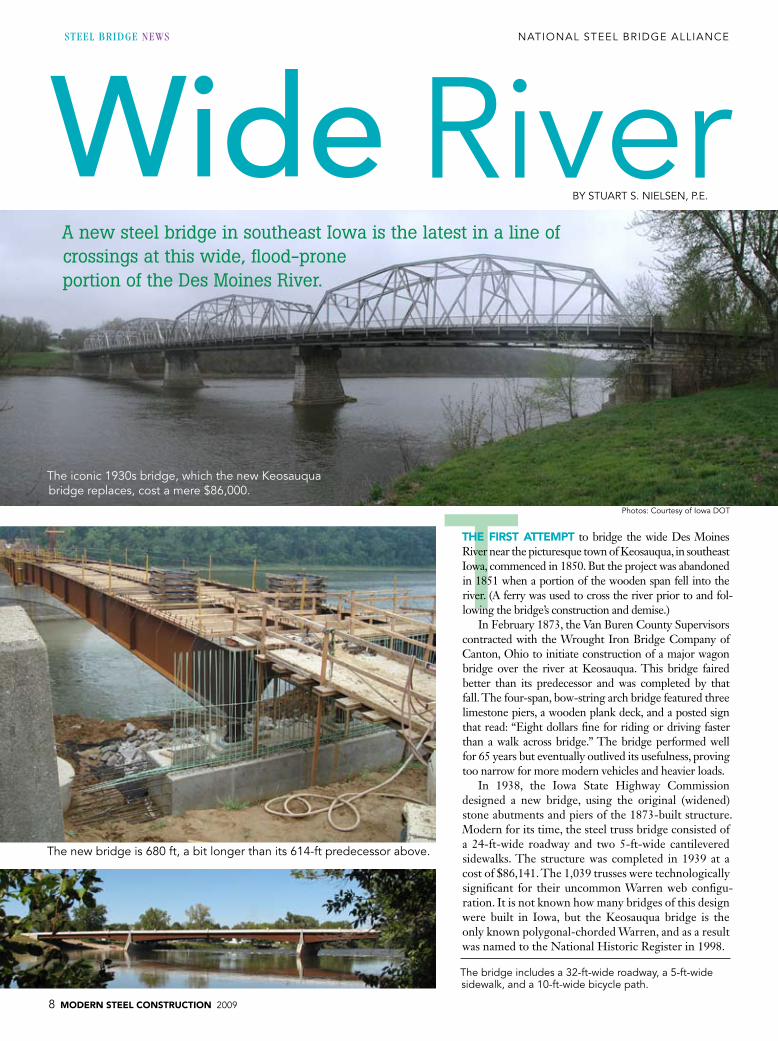
TThE FIRST aTTEMpT to bridge the wide Des Moines River near the picturesque town of Keosauqua, in southeast Iowa, commenced in 1850. But the project was abandoned in 1851 when a portion of the wooden span fell into the river. (A ferry was used to cross the river prior to and fol-lowing the bridge’s construction and demise.)
In February 1873, the Van Buren County Supervisors contracted with the Wrought Iron Bridge Company of Canton, Ohio to initiate construction of a major wagon bridge over the river at Keosauqua. This bridge faired better than its predecessor and was completed by that fall. The four-span, bow-string arch bridge featured three limestone piers, a wooden plank deck, and a posted sign that read: “Eight dollars fine for riding or driving faster than a walk across bridge.” The bridge performed well for 65 years but eventually outlived its usefulness, proving too narrow for more modern vehicles and heavier loads.
In 1938, the Iowa State Highway Commission designed a new bridge, using the original (widened) stone abutments and piers of the 1873-built structure. Modern for its time, the steel truss bridge consisted of a 24-ft-wide roadway and two 5-ft-wide cantilevered sidewalks. The structure was completed in 1939 at a cost of $86,141. The 1,039 trusses were technologically significant for their uncommon Warren web configu-ration. It is not known how many bridges of this design were built in Iowa, but the Keosauqua bridge is the only known polygonal-chorded Warren, and as a result was named to the National Historic Register in 1998.
The iconic 1930s bridge, which the new keosauqua bridge replaces, cost a mere $86,000.
A new steel bridge in southeast Iowa is the latest in a line ofcrossings at this wide, flood-prone portion of the Des Moines River.
BY STuART S. NielSeN, P.e.
Photos: Courtesy of iowa DoT
The bridge includes a 32-ft-wide roadway, a 5-ft-wide sidewalk, and a 10-ft-wide bicycle path.

2009 MODERN STEEL CONSTRUCTION 9
The 1939-built bridge lasted longer than both of its predeces-sors but in early 2003, it was determined that the structural integrity of the truss was rapidly declining. Hence, a new Keosauqua bridge would have to be built.
Detour not an OptionFor a typical bridge replacement, an engineer can theoretically de-
sign a new structure without leaving the confines of his or her office. But this wasn’t an option for the Keosauqua crossing because of the bridge’s historic value and unique surroundings. Designers for the new bridge spent a great deal of time on-site to get a feel for the local landscape and the historical significance of the crossing. The 1939 structure was located in the heart of Keosauqua and provided a path across the river to the 1,653-acre Lacey Keosauqua State Park, one of Iowa’s largest state parks and a year-round destination for tourists. It had survived numerous floods and was considered one of the scenic high points for those paddling on the river.
The first step in the process of replacing the truss bridge was meeting with the citizens of Keosauqua. The Iowa Department of Transportation (IDOT) held a series of town meetings to gauge the needs and desires for the new bridge. Aesthetics was high on the list of concerns but other issues, such as traffic staging, also had a major impact on the concepts for the new bridge. From a practicality standpoint, closing the existing bridge’s roadway would have required a 22-mile detour and was therefore deemed unacceptable. Besides creating a major inconvenience for motor-ists, cross-river access via the bridge was required for school buses and emergency vehicles.
A bridge committee of local citizens and officials was formed to help guide the design of the new bridge and eventually decided on a girder-style bridge. While this would be the easiest style of bridge to stage, it was quite a change for the residents to go from a towering, above-deck structure to a lower, more subdued design.
Three SpansA three-span variable-depth weathering steel girder bridge was cho-
sen for the replacement. The first stage was built along side of the existing truss bridge, using a three-girder cross section, allowing the existing truss to carry traffic. This also had the benefit of allowing residents to view the construction of the new bridge from the sidewalk of the old bridge.
Two lanes of traffic were then placed on the new bridge, the old bridge was demolished, and then the new bridge was widened to its final width by adding an additional two girders. This scenario allowed for two lanes of traffic to flow for the majority of the construction period, easing con-cerns of long traffic detours.
The new Keosauqua bridge has a five-girder cross-section, spaced at 11 ft, 7 in., with two 210-ft end spans and a 260-ft center span, making the new bridge 680 ft long in all, slightly longer than the 614-ft truss bridge. A 32-ft-wide roadway was chosen to reduce costs and help with traffic calming of vehicles coming down from a hill on
the south end of the bridge. The bridge also features a 5-ft sidewalk and a 10-ft-wide bike path.
The welded plate girders range in depth from 6 ft at the center of the spans to close to 12 ft at the piers. Fabricated by the Stupp Bridge Company in Bowling Green, Ky., they were shipped by truck in 120-ft segments to the bridge site. More than 800 tons of struc-tural steel was used in the construction of the bridge.
Aesthetic features of the bridge include two overlooks on the east side of the bridge, custom railings, and dramatic piers. The piers and abut-ments use form liners to mimic limestone and were painted using high-quality stains. Stones rescued from the limestone piers of the old truss bridge top the new pier towers, allowing visitors to actually reach out and touch the past. In fact, the old limestone piers were also reused as revet-ment to dress the shoreline around the new abutments.
The design team received a “Best Practices in Context-Sensitive Solutions, Notable Practice” award from the American Association of State Highway and Transportation Officials (AASHTO) in 2006 for the project. Construction was completed last fall.
Stuart S. Nielsen is a transportation engineer specialist with the Iowa De-partment of Transportation’s Office of Bridges and Structures.
bridge Designeriowa Department of Transportation, office of Bridges and Structures
Steel FabricatorStupp Bridge Company, Bowling green, ky. (AiSC/NSBA Member)
More than 800 tons of structural steel was used in the construction of the bridge.
The welded plate girders range in depth from 6 ft at the center of the spans to close to 12 ft at the piers.

10 MODERN STEEL CONSTRUCTION 2009
steel bridge news NATioNAl STeel BRiDge AlliANCe
Over the Rails
Kansas City—Kansas—finds a new way to span a vast rail yard and link the north and south sides of town.
BY BReNDA P. FoRee, P.e.
TThE U.S. 169 (7Th STREET) bRIDgE in Kansas City, Kan. accom-plishes quite a lot for just one bridge. Located between Kansas Avenue and Interstate 70, it spans over several Union Pacific Railroad and Kansas City Terminal Railway tracks. It serves as a primary route to the University of Kansas Medical Center - Kansas City from north of I-70. And above all, it provides a vital link between the north and south sides of town.
The original 34-span structure was designed in the early 1920s by Harrington, Howard and Ash Consulting Engineers, a prede-cessor of HNTB Corporation; construction was completed in 1924. To accommodate the Muncie Expressway (I-70) construction in 1959, the north five spans were buried, shortening the structure to 1,450 ft. The bridge was widened from two to four lanes in 1972.
Rehab TimeBy the late 1990s the aging bridge was at a proverbial and literal
crossroads. The Kansas Department of Transportation (KDOT) contracted with HNTB in 1999 to perform a discovery phase study to evaluate repair, rehabilitation, and replacement options for the bridge. The study was completed in 2003 and established
design criteria, scope of construction improvements, and construc-tion cost estimate; the resulting recommendation was to replace the entire bridge.
Prior to the beginning of the study, KDOT had authorized funds to replace the bridge’s reinforced concrete deck girder spans only—approximately 40% of the bridge. The remainder of the bridge would remain and consisted of two spans of continuous welded structural steel plate girders and nine simple spans of riv-eted structural steel plate girders. The study estimated the bridge replacement cost at $21.1 million.
HNTB completed final design and bid plans for the replace-ment bridge in early 2006 and the project was let for construction in September 2006, with a target completion date of December 2008. General contractor Hawkins Construction Company built the bridge’s south unit and subcontracted the construction of the north unit to United Contractors, Inc.
Features, Constraints, and ImprovementsThe replacement structure is a 10-span two-unit steel plate girder
bridge and is designed to carry current AASHTO live load, HL-93.
kansas Cityotherin the
Photos by Brenda Foree

2009 MODERN STEEL CONSTRUCTION 11
The bridge’s typical section consists of northbound and south-bound 30-ft-wide roadways, with a 5-ft 6-in.-wide sidewalk located on the west side of the structure. Pedestrians are separated from the southbound roadway by a 42-in.-tall concrete safety barrier. The middle one-third of the bridge tapers out to provide for 650 ft of southbound left turn storage for Kansas Avenue at the south end of the bridge. The total length of the new bridge is 1,464 ft.
The numerous railroad tracks, existing bridge foundations, and an existing sanitary sewer provided limited locations for the new bridge foundations and added complexity to the design and con-struction of the bridge. The number of piers in the new bridge (nine) was reduced substantially from the existing 28 piers. The continuous movement of rail cars had to be accommodated during existing bridge demolition and new bridge construction.
Span lengths in the south unit are 110 ft, 125 ft, 165 ft, 180 ft, and 126 ft, while spans in the north unit are 160 ft, 160 ft, 151 ft, 136 ft, and 146 ft. The south five piers are not skewed, but the north four piers are skewed from 10° to 26°, resulting in girder lengths that vary by as much as 10 ft in one span.
Structural steel plate girders were chosen as the preferred struc-ture type early in the preliminary design process due to the variable structure width, unbalanced spans, and span lengths up to 180 ft. An additional benefit of structural steel is reduced dead load and cor-responding lower substructure and steel pile foundation costs.
The girders are composite, with concrete deck throughout. The partially stiffened webs are 48 in. deep in the south two spans and 66 in. elsewhere. Grade 50 unpainted weathering steel was chosen to minimize future maintenance costs, and the girders are painted only at unit ends, adjacent to expansion joints.
The bridge’s vertical profile is constrained by the Kansas Avenue intersection on the south, the railroad tracks, and the I-70 bridge on the north. The existing profile proceeds north from Kansas Avenue at a positive grade of 5.53%. Although this steep grade could not be reduced on the new bridge, the profile was lowered to keep standard slopes within existing right-of-way and to meet the desired design speed criteria of 50 mph. The new profile eliminates the “dip” at the abandoned railroad depot, increasing stopping sight distance and de-sign speed. Steel handrails are provided on each side of the sidewalk to meet ADA requirements.
The new bridge provides the required 23-ft 6-in. minimum vertical clearance over the below railroad tracks, eliminating the existing bridge’s substandard vertical clearances at ten of the tracks. Barriers, fences, and pier collision walls meeting current Ameri-can Railway Engineering and Maintenance-of-Way Association
(AREMA) criteria are provided. Besides the typical site constraints, the bridge was also re-
quired to stay within spatial boundaries set by agricultural in-frastructure: The horizontal alignment is constrained by the Archer Daniels Midland (ADM) grain elevators located within 6 in. of the west fascia of the original bridge. The baseline of the new bridge is shifted slightly east of the existing U.S. 169 centerline to avoid impacts to the ADM elevators and to bet-ter align with the I-70 bridge north of the project and with the lanes south of Kansas Avenue. The alignment provides im-proved right turn radii at the I-70 entrance and exit ramps at the north end of the bridge.
In order to maintain one northbound and one southbound lane during construction, the existing structure was removed and the replacement bridge built in two phases. The east por-tion of the new bridge was completed in 2007 while traffic used the west half of the existing bridge. During 2008, traf-fic was shifted to the east portion of the new bridge while the west portion was being constructed. Erecting the phase 2 girders in the south unit between the grain elevators and the phase 1 girders presented a tight window for construction. As such, girder erection began at the south abutment and pro-ceeded northward using the previously erected structure as a platform.
The bridge opened on time last December, providing an up-to-date structure for the vital link between north and south Kansas City, Kan.
Brenda P. Foree is a project manager with HNTB Corporation.
Ownerkansas Department of Transportation
DesignerhNTB Corporation, overland Park, kan.
Steel Fabricator and Detailer
Delong’s, inc., Jefferson City, Mo. (AiSC/NSBA Member) general Contractor for South Unithawkins Construction Company, omaha, Neb.
Subcontractor for North Unitunited Contractors, inc., Johnston, iowa
The new 7th Street bridge in kansas City, kan. is a 10-span two-unit steel plate girder bridge.
The new bridge provides the required 23-ft 6-in. minimum vertical clearance over the below railroad tracks.

12 MODERN STEEL CONSTRUCTION 2009
national student steel bridge competition
L
Full houseSToRY AND PhoToS BY geoFF WeiSeNBeRgeR
LaS VEgaS IS TRaDITIONaLLy paCkED on Memorial Day weekend. The usual four-hour drive from Los Angeles can take more than twice that long, the airport is mobbed, and the taxi lines are a major hassle—although quite entertaining as well.
Away from the chaos and revelry of the Strip, a different type of intensity was on display this past Memorial Day weekend in Vegas—and it was focused on something a bit more productive than the activities typically associated with Sin City. While every-one else was in town on vacation, college students—around 550 of them—were doing something constructive. More specifically, they were building steel bridges.
The occasion for such prolific, focused activity in such a lei-sure-oriented locale was the National Student Steel Bridge Com-petition (NSSBC), which took place at the University of Nevada, Las Vegas’ Thomas and Mack Center. “We truly came into this determined to be like no other, and we exceeded all expectations,” said Vik Sedhev, UNLV engineering student and 2009 NSSBC student director.
In all, 46 teams of university-level civil engineering students from the U.S. and Canada assembled, displayed, and tested their creations in the annual contest. The teams are narrowed down from nearly 200 teams that participate in 18 conference competi-tions around the country.
“At this level, they really know what they’re doing,” said John Parucki, who has been the head judge of the competition for the past 15 years. “We get the cream of the crop every year, and they get to compete against each other. You can’t get any more real-world than this.”
NSSBC is a joint effort between AISC and the American Soci-ety of Civil Engineers. It started as a regional competition in the upper Midwest in the mid-1980s and grew into a national compe-tition by 1992. Generally, the top three teams from each confer-ence competition make it to the national level. And improvement between the two levels is the norm more than the exception.
“Once the top teams get back from regionals, they really get to work to improve their scores,” explained Scott D. Schiff, pro-fessor of civil engineering and director of the Wind and Struc-tural Engineering Research Facility at Clemson University.
“Most teams can cut 10 to 25% off of their construction time by improving their connections, developing new assembly schemes, and just practicing for countless hours so that every movement is memorized.”
Three teams at this year’s competition built their bridges in un-der four minutes, and several others weren’t too far behind; the majority of the field finished in under 15 minutes.
But construction speed is only one of six categories in which the bridges are judged. Stiffness, lightness, economy, display, and efficiency are also assessed, and the best combined score across all six categories wins. Every year, the design parameters change slightly to meet the Problem Statement, which this year called for teams to create a scale model of an attractive and functional replacement for a century-old highway bridge spanning a scenic river. In past competitions, above-deck steelwork was part of the program, but this year everything had to remain below the deck. Also, this year’s bridges were required to be 20 ft long and ca-pable of carrying 2,500 lb.
Future engineers pack UNLV’s Thomas and Mack Center for the annual National Student Steel Bridge Competition.
The lafayette College team wore their fasteners on their sleeves—with a little help from magnets.

2009 MODERN STEEL CONSTRUCTION 13
prep WorkStudents design and build the bridges themselves and begin the
whole process months in advance. The assembly is practiced over and over until it is perfected; in many cases, teams will assemble their bridges more than 100 times.
“We design our bridge in the fall semester, we fabricate it for one week over winter break, and practice construction in the spring semester,” explained Alex Pschorr, a co-chair for the University of Wisconsin–Madison team. “We tried to determine how many times we practiced putting in together, and we counted over 120 construction runs (dress rehearsals).”
In some cases, the design changes at the last minute—before the regional competition and sometimes even between the conference and national competitions. “We actually had our bridge built a month be-fore regionals, then decided to scrap the entire truss and throw it away,” noted Eric Gunderson, North Dakota State University’s co-captain; NDSU has won the competition five times in the last 10 years. “We designed and fabricated a new truss for regionals in less than two weeks. That bridge got us to Vegas and with a few more minor changes after regionals, we were ready to compete at nationals. It took us two bridges to get it right, but in the end we got what we wanted.”
One team, California Polytechnic – San Luis Obispo, put ap-proximately 1,500 hours into their bridge design and construction.
“We redesigned the entire bridge after regionals, when we realized the design flaws the bridge had,” said Mike Ginther, the team’s captain. “The construction team spent the last three days before
the competition practicing, going through 15 to 20 run-throughs building the bridge.”
In fact, Ginther was so involved with the project that it became inescapable, even in sleep. “Most of my ideas for the bridge came to me while I was sleeping,” he said. “The last six months, all my focus was on the bridge.”
It’s OnThe two-day competition began on Friday, which involved
the most arbitrary segment, the display judging. The Rules Com-mittee—made up of 10 volunteers from the steel industry and academia—made their rounds and decisions on which entries they found most aesthetically pleasing. (So did I.)
Walking amongst the entries was like walking through a muse-um of bridge design. The sheer variety of colors, styles, and designs was amazing, especially given the parameters to which the teams must adhere. Several bridges were painted; many were decked out in school colors, while the University of Hawaii at Manoa’s bridge was metallic purple. Bridges were constructed with a variety of framing types, including joists, trusses, box trusses, HSS, or any combination thereof. Some were Spartan while others were ele-gant; some were simple while others were complex. And of course, there was flare. The University of California at San Diego’s entry sported silver tridents, and Kansas State University’s name plate (every bridge is required to display the school’s name) featured the school’s well-known wildcat logo.
The bridge has left the building (top). kansas State’s team performing load testing (bottom).
gray and flat with X-bracing was just one of many bridge styles (top). The university of California, San Diego’s team in action (bottom).

14 MODERN STEEL CONSTRUCTION 2009
From Museum to RacetrackWhile Friday offered an opportunity to look over the bridges at a
leisurely pace and observe the students in a somewhat relaxed setting, Saturday was a different story and featured the most exciting part of the competition: the timed construction of the bridges. Whatever pre-conceived notions I had about a bunch of engineering students build-ing bridges were replaced by what felt more like a swim meet—and the venue, a college basketball arena, only added to the atmosphere. Students raced back and forth between their material staging areas and the bridges in an effort to beat the clock. They yelled encour-agement and directions to one another—as did “coaches,” from the sidelines. And many teams even had their very own cheering section in the stands, typically comprised of the rest of the team.
Here’s how it works: Teams are compiled of 10-20 members, al-though only four or five get to build. The judges—there are almost 50, many of them local and all involved in the steel industry in some form or fashion—referee all areas of the competition except for the aesthetics portion.
The competition takes place in a designated (by tape) area, the build station; there were five build stations in all, so at any given point, you could watch five teams competing at once. Teams—who must wear safety gear such as hard hats and construction boots throughout the competition—lay out their bridge materials at one end of the build station, the staging area. At the other end of the sta-tion is the assembly area. Once the clock starts, the runners (there are one or two) run the members across an open area, one by one, to the assemblers. As the assemblers put the bridge together, the runners go back and forth between the assembly and staging areas until the bridge is complete. The action is much like that of a relay, except instead of handing off the baton, the runners are handing off steel. Each runner has to wait outside of the assembly area until
the assemblers finish connecting the previous piece, before handing over the next piece; it can be a waiting game on both ends. The ideal assembly scenario is when a runner hands off his piece and the as-sembler has it in place and is ready for the next piece right when the runner returns with it, in a continuous fluid process.
Verbal encouragement isn’t only motivating, it can also be crucial. Shouts of: “Watch that pier!” “Check the bottom chord bolts!” “Bolt in the water!” and similar guidance can be heard throughout. “In the heat of battle, it’s easy to forget things,” said Mike Engestrom, a member of the NSSBC Rules Committee and technical marketing director with Nucor-Yamato Steel, one of the event’s sponsors.
As this year’s competition featured a “river” (also designated by tape), the team members were not allowed to step into it and were penalized if they did so. Fasteners had to be held by the assemblers in a pouch. There was a lengthy discussion over what constituted a
“pouch” at the team captains’ meeting, which took place the night before. Two teams came up with the idea of taping magnetized strips to their arms in order to have easier access to their fasteners.
When the bridge is complete, the clock stops. This year’s fastest time was delivered by State University of New York (SUNY) Canton, which came in at just over three minutes. However, in some ways, the clock doesn’t stop with the construction portion. Additional time may be added due to penalties given during the load test, much like a hurdler being penalized for knocking down a hurdle even if he crosses the finish line first. Violations include items such as a nut falling off its bolt during transport to the load testing area or a nut not being fully engaged—or again, stepping or dropping something in the river. Hence, while teams strive for the fastest assembly, they must also account for a quality as-sembly. (Erection time plays a factor into another of the competition’s categories, construction economy, which also is determined by the number of builders and the number of temporary piers used.)
Teams raced against the clock in the build portion of the competition.

2009 MODERN STEEL CONSTRUCTION 15
Surveying StrengthFollowing the construction portion,
teams put their bridge’s strength to the test at the load stations, where lateral and ver-tical load testing is performed. Safety sup-ports are placed below the bridge, should one happen to collapse. For the lateral test, a load of 75 lb is placed on one side of the bridge and a “sway target” is established on the other side, then a 50-lb lateral pull is applied at the sway target and the sway is measured. Sway must not exceed 1 in., or the bridge does not pass the test.
Vertical load testing begins by having the team members place two decking units near opposite ends of the bridge and adding 100 lb to each of them. From here, 1,150 lb is added to one unit. Two targets are established longi-tudinally at the center of the decking unit, on either side of the bridge. Downward vertical deflection is measured at both targets. Next, 1,150 lb is placed on the other decking unit. There’s only one target at this end. (It too is established longitudinally at the center of the decking unit, but only on one side.) The ab-solute value of vertical deflection at this tar-get that occurs from when the load is added to the first unit to when it is added to this one, is measured.
Unfortunately, even at the national level, failures can occur. It happened to one of this year’s teams when a weld failed during
the load testing. Factors such as a bridge’s design changing between the conference and national levels can introduce last-minute mistakes that prove costly during the moment of truth. While discouraging in a competition setting, mistakes can be learned from and provide motivation and caution for future competitions and, eventually, the real world. As Parucki put it, “Failures can be ‘eureka’ moments.”
Weighing InThe last step for the bridge is to un-
dergo a weight test. Simply put, the lightest bridge wins this category (although penal-ties can be assessed based on factors from the other portions of the competition). To weigh the bridges, they are placed on what could be described as a four-part scale—one for each footing.
Weight also plays into the final cat-egory, structural efficiency; aggregate deflection from the vertical load test also factors into this category.
Final ResultsIn the end, the sum is the whole of its
parts. Sacrifices in one area might lead to advantages in others. While timing and cost are important, “Being able to con-struct the design—that’s what’s most valu-able,” said NSSBC judging veteran T. Bar-
tlett Quimby, an associate vice provost at the University of Alaska Anchorage.
SUNY College of Technology at Can-ton, after placing first in two categories last year, won the overall competition this year. NDSU took second, while Lakehead Uni-versity came in third.
While it’s certainly nice to win, the compe-tition is really about preparing future engineers for the real world. According to UC Davis team member Tyler Hickox, “I have learned much from my experience with [the competi-tion] and have incorporated many new ideas into what I will make my senior thesis.”
“The competition is an invaluable part of my college career,” said Eric Michal, project manager for the University of California – Berkeley team. “Not only are we able to apply the classroom knowledge we learn, but working and managing a group of individuals is greatly beneficial for what is to come in the real world—not to mention an unbelievable and unforgettable experience.”
For the full results of the overall competition and the individual categories, visit www.aisc.org/steelbridge. Also, the 2010 NSSBC will be hosted by Purdue University May 28-29 in West Lafayette, Ind. The 2010 rules will be posted at the above link this August.

16 MODERN STEEL CONSTRUCTION 2009
TNew
BY BRAD MilleR, P.e.
Recycling and reusing parts of an old bridge means everybody wins.
ThE bLaCk bRIDgE NEaR MILLTOWN aND bONNER, MONT., was reconstructed in 2008, but not in the ordinary way. The old bridge was a four-span pedestrian bridge with two steel Pratt truss spans and a short concrete approach span on each end. The new bridge has all new foundations, a much longer center span and new prefabricated steel approach spans. Splitting one old truss span near mid-span and adding new truss bays enabled lengthening the center span and avoided impending foundation problems. The truss lengthening was made possible, from an engi-neering standpoint, by removing the heavy, old concrete deck and installing a new lightweight timber deck.
project Development and EngineeringThe old Black Bridge, located five miles east of Missoula, Mont.,
was constructed in 1921 over the Milltown Reservoir, part of the Blackfoot River near its confluence with the Clark Fork River. In recent years it has been open to only pedestrian traffic. With the removal of the 100-year-old Milltown Dam as part of a su-perfund clean-up site, and the loss of the reservoir behind it, the 85-year-old Black Bridge, would be subjected to swifter stream ac-tion and scour than it was originally designed for. The Blackfoot River channel was expected to degrade 12 ft or more in the area of the bridge, undermining the center pier that was founded on relatively shallow spread footings. There also were two old piers from a previous bridge that obstructed the channel contributing even more to potential scour. An alternate study was performed and the decision was made to replace the structure with a new pedestrian bridge.
likeJust
N A T i o N A l S T e e l B R i D g e A l l i A N C e NEWSSteel BridgeSePTeMBeR 2009

2009 MODERN STEEL CONSTRUCTION 17
The citizens of nearby Milltown and Bonner, already sore from losing their historic dam and other significant structures, formed a Save Our Bridge (SOB) committee and won support from Missou-la County to save a significant portion of the existing truss spans. Tim Elsea, Missoula County Engineer, worked closely with HDR Engineering to achieve this goal while satisfying the roughly 230-ft main span length dictated by environmental constraints. HDR determined that it could incorporate one of the truss spans into the new bridge by lengthening it to 222 ft, sufficiently close to the en-vironmental requirement for the main span, by reducing the dead load imposed on the truss. This was done by replacing the heavy concrete deck with a lightweight timber deck.
HDR bridge engineers analyzed the lengthened truss model and determined that this was a viable option but would cost sig-nificantly more than an all-new bridge. Missoula County opted to
Brad Miller, P.E., is a senior bridge project manager and professional associate with HDR Engineering Inc., Missoula, Mont.
above: Before, two 166.5-ft spans and four piers in the water.
Left: After, one 222-ft span on new piers on the banks.
The original bridge built in 1921 had two 166-ft-long truss spans with short approach spans.
in 2008 the bridge was reconstructed. one truss span was lengthened to 222 ft using parts from the second truss as well as new components, and new approach spans were added.

18 MODERN STEEL CONSTRUCTION 2009
go with the lengthened salvaged truss span and the final bridge design was modified to include this concept. Pleased by the out-come, the citizens of Milltown and Bonner amended the “Save Our Bridge” sign that had been installed on the old bridge to read
“Saved Our Bridge.”The original Pratt truss consisted of
nine 18.5-ft truss panels with an 8- to 10-in.-thick concrete deck. By replacing the heavy concrete with a lightweight wood deck, three additional truss panels could be inserted into the center of the bridge, lengthening it from 166.5 ft to 222 ft. The lengthened truss was completely re-evaluated for pedestrian, emergency, and maintenance loads as well as seismic and wind loads.
Reducing the dead load was done pri-marily by replacing the concrete deck with a 1.5-in. timber deck using long-lasting Ipe hardwood, also referred to as ironwood. Eliminating the cantilevered sidewalk on the downstream side of the bridge, which was used when the bridge served as a high-way bridge, and narrowing the deck width inside the truss from 19.5 ft to 16 ft reduced the dead load even more. The net reduc-tion in dead load was about 2,500 lb/ft of truss after taking into account the weight of lateral bracing added due to the increase in truss span and to offset the bracing com-ponent lost in removing the concrete deck, as well as miscellaneous steel added in the deck and rail system.
An ironwood deck, which does not require chemical preservative treatment, was selected instead of a treated wood deck because this bridge reconstruction project was part of a large superfund clean-up effort and the agen-cies involved were very sensitive to possible environmental concerns resulting from the
use of treated wood over water. This was more of a preference than a real issue since treated wood over water is still acceptable if properly designed and installed.
The final bridge configuration consists of a new 98-ft-long prefabricated steel truss approach span at each end of the re-furbished center truss span. The main truss span is wider than the approach spans and offers special overlooks for fishing and rec-reation. Portions of the unused second span were used to replace damaged parts on the reconstructed span and old steel string-ers were incorporated into the new center portion. All the steel was painted black to match the original color of the bridge.
The final structure has an entirely new substructure consisting of concrete drilled shafts at the abutments and piers. Each pier consists of two 5-ft diameter drilled shafts extending approximately 43 ft below the ground line. Each abutment has two 2-ft di-ameter drilled shafts extending 22 ft below the base of concrete cap. The old truss span was removed and re-installed using a work bridge and heavy moving equipment.
OwnerMissoula County, Mont.
Structural EngineerhDR engineering inc., Missoula, Mont.
Steel FabricatorRoscoe Steel, Missoula, Mont. (AiSC Member)
Steel Fabricator – approach SpansCoNTeCh Bridge Solutions inc., Fort Payne, Ala. (AiSC/NSBA Member)
general ContractorFrontier West llC, Missoula, Mont.
Returning to the SceneRoscoe Steel had its beginnings
in the Minneapolis-based Security Bridge Company, the general contrac-tor for the Black Bridge in 1921. The area manager for security was W.P. Roscoe, Sr. who went on to found W.P. Roscoe Co. (a bridge contracting firm whose history spanned from 1923 to 1974). his son W.P. Roscoe, Jr. started Roscoe Steel & Culvert Company, inc. in 1953 and subsequently his grand-son, Jim Roscoe, bought control of that company in 1975.
For the Black Bridge reconstruction project, Roscoe Steel developed a 3D CAD model of the lengthened por-tion of the truss along with other new members in order to ensure the correct dimensions of new truss elements and
bolted connections.
New hSS2×2×3∕16 supports running longitu-dinally between the stringers stiffen the new wooden deck, enabling multiple 2-in. by 8-in. planks to carry the single-wheel loads from emergency and maintenance vehicles.

2009 MODERN STEEL CONSTRUCTION 19
one old truss span was removed to the river bank for reconstruction, where it was split apart and new steel added to lengthen the span. Steel from the second truss span was used to replace damaged parts and steel stringers were used in the added truss bays.
The old steel of the existing truss was cleaned by 5,000-psi water jetting with a roto-tip nozzle. Cleaning water and paint debris were collected, filtered and recycled. The reconstructed truss, along with the new approach spans, were painted semi-gloss black using a three-coat moisture cure urethane paint system supplied by Wasser.

20 MODERN STEEL CONSTRUCTION 2009
AShort-Span Bridges
BY AToRoD AziziNAMiNi, Ph.D.
Steel provides a simple and economical solution.
aLMOST 45% OF ThE bRIDgES in U.S. bridge inventory are less than 60 ft in length. Most are simple spans located on county roads. Many of these short-span bridges are either structurally de-ficient or functionally obsolete and need to be replaced. It is essen-tial to develop alternatives that are economical, can be constructed using light construction equipment and have long service life with minimal maintenance.
A new solution, referred to as the Folded Plate Bridge System, offers an economical and exciting solution for many of the nation’s bridges with maximum span lengths up to 60 ft. The system consists of a series of standard shapes that are built by bending flat plates into inverted tub sections using a break press (see Fig. 1) and has many advantages for both steel fabricators and bridge owners. The maxi-mum span length for this system is currently limited to about 60 ft, reflecting the longest press breaks that are available in the industry.
Folded plate girders suitable for different span lengths differ only by their cross-sectional dimensions. More specifically, varying the width of the top and bottom flanges and the depth of the web while keeping the plate thicknesses to either 3⁄8 in. or ½ in. can ac-commodate span length requirements. The different top and bot-tom flange widths and web depth can easily be accommodated by changing the bend locations, so fabricators can build folded gird-ers very quickly while only stocking two plate thicknesses. That is important because delivery of steel bridge girders in a timely manner is an important issue for the bridge owners.
The shape of the cross section for the Folded Plate Bridge Sys-tem has several key advantages in its design and construction:
➜ The inverted tub shape produces a very stable bridge girder configuration that does not require internal or external cross frames for either local or global stability. A single cross frame could cost as much as $1,000, so eliminating cross frames helps reduce cost. It also eliminates a major factor responsible for fatigue and fracture observed in old steel bridges. Further, the Folded Plate Bridge System is very user friendly during the construction phase. For example, the formwork for cast-ing concrete can be accomplished using conventional equip-ment and practices.
➜ The top flange of the Folded Plate Bridge System is wide enough (about 25 in. to 35 in.) to serve as a work platform. That itself can reduce many construction hazards associated with workers walking on girders during construction.
➜ Box or tub girder bridges are very efficient bridge systems but usually are used only for longer span bridges (longer than about 300 ft). That is in part because of the inspection is-sue. Longer span lengths result in tub sections that are deep enough to allow internal inspection. However, for short-span bridges (less than 60 ft) the depth of the box needed is so small that it prohibits crawling inside the box for inspection. This is one of the reasons for not using box girder bridges for short-span bridges. The cross section of the Folded Plate Bridge System, however, is open on the bottom side, making inspection very easy.
steel bridge news NATioNAl STeel BRiDge AlliANCe
A New Era for
Fig. 1 Typical cross section for the Folded Plate Bridge System. Dimensions vary based on span length.
Atorod Azizinamini, Ph.D., is a professor of structural engineering at the Univer-sity of Nebraska– Lincoln. He also serves as director of the university’s National Bridge Research Organization. For fur-ther information about the Folded Plate Girder Bridge System, contact Professor Azizinamini at 402.770.6210.

2009 MODERN STEEL CONSTRUCTION 21
Fabrication and ConstructionOne of the advantages of the Folded Plate Bridge System is its
promise for rapid delivery. The concept uses only two plate thick-nesses—3⁄8 in. and ½ in.—and bending the plate to specified shapes is not time consuming. These attributes combined allow rapid fab-rication and delivery. For example, many U.S. electrical utility pole manufacturers have the capability of building one folded plate girder in less than a minute.
Recently, the trend within the bridge construction industry has been toward reducing construction activities on the bridge site and eliminating the interruption to traffic. The Folded Plate Bridge System can be constructed using conventional construction tech-niques as well as using principles of Accelerated Bridge Construc-tion. In the case of conventional construction procedures, readily available construction equipment could be used to build the form-work for casting the concrete deck (see Fig. 2 and Fig. 3).
An alternate and perhaps better approach when using the Folded Plate Girder system to construct short-span bridges is to use pre-fabricated elements. The tributary width of concrete deck for each folded plate girder could be cast on the girder prior to shipping to the site. In this scenario each prefabricated bridge element would be in the form of a folded plate with a precast top deck (see Fig. 4).
A typical two-lane county type bridge will require three such folded girder sections placed side by side and connected longitudi-nally. A number of approaches can be used to connect pre-decked girders in the longitudinal direction. A 40-ft.-long folded plate girder with precast deck will weigh about 24,000 lb, allowing use of a relatively lightweight crane on the construction site.
The development of the folded plate bridge system is a result of re-search at the University of Nebraska-Lincoln. Ongoing research and development work is nearing completion and the new bridge system will be available for field application by December 2009.
Fig. 2 Conventional form-ing materials and meth-ods can be used to form the concrete deck on the folded plate girder.
Fig. 3 A folded plate girder with deck forms and reinforcing steel in place. Note the studs on the girder and the sizable work platform it provides.
Fig. 4 With the concrete deck in place, several sections of a folded plate girder bridge can be stacked and shipped to the site on one trailer.
Photos provid
ed b
y Atorod
Azizinam
ini.

22 MODERN STEEL CONSTRUCTION 2009
P
over the RiverBY CRAig A. MATToX, P.e.
The new Topeka Boulevard Bridge spans a river, a railroad, a flood protection levee system, and local streets.
pRELIMINaRy DESIgN STUDIES for this bridge replacement looked at com-posite steel girder spans and precast prestressed girder spans. The final structure needed to carry 23,000 vehicles per day on a viaduct spanning a number of dif-ferent obstacles: the Kansas River, four side streets, the U.S. Corps of Engineers Kansas River levee system and three tracks of the Union Pacific’s mainline carry-ing 120+ trains per day.
The design was to be flexible enough to be readily widened in the fore-seeable future should traffic growth continue at its current pace. In addition, the design would have to be able to accommodate carrying two 24-in. water mains and a 10-in. high pressure gas line supplying the metropolitan area north of the river. The result of the design study was for a steel superstructure
steel bridge news NATioNAl STeel BRiDge AlliANCe
and More
using various styles of steel beams and girders helped engineers avoid conflicts with existing streets and buried utilities as well as maintain clearances.
Photos by Craig Mattox.
Craig A. Mattox, P.E., is managing partner/owner of Finney & Turnipseed Transportation & Civil Engineering, Topeka, Kan.

2009 MODERN STEEL CONSTRUCTION 23
At least partly to maintain good aesthetics, observation deck extensions were added to the bridge at the gateway tower piers at the levee on each side of the river to harmonize with the widened substructure.
Divided into four units for planning purposes, the 3,210-ft Topeka Boulevard Bridge includes 24 spans ranging from as little as 70.5 ft to as much as 215 ft.
Although the bridge is constructed of weathering steel, the exterior girders and exposed bearing devices were painted for aesthetic reasons.
3,209.56 ft long on a substructure widened to accommodate future expansion. The new bridge is four lanes wide with room for an additional lane to be added to each side. Both sides of the roadway have a 6-ft-wide sidewalk that meets ADA requirements.
Aesthetic improvements were added to the structure based on public comments. A steel sign truss spans gateway towers located at each river levee. At this same location, an observation deck extension on a simple span welded girder was added to the bridge to offset the widened substructure. The exteri-or girders and exposed bearing devices were painted for aesthetic reasons. The red color was selected and presented to the public in a series of public meetings.
Steel erection took place over an eight-month period, including several delays due to flooding. The project required 22 months to construct and was opened to traffic in August 2008.
This bridge illustrates the flexibility offered by structural steel. The structure used three types of steel spans. Composite rolled (40-in.) beam sections were used for Units 1 and 3, each with five spans rang-ing from 70 ft to 95 ft. Composite uniform depth welded plate girders were used for Unit 4, where the five spans were between 103 ft and 141 ft. The composite haunched welded plate girders used for the nine spans in Unit 2 ranged from 146 ft to 215 ft. The use of each these different solutions allowed flexibility in avoiding conflict with existing streets and buried underground obstructions. Their use also helped in maintaining vertical and horizontal clear-ance requirements set forth by the Corps of Engineers for the levee and by the rail-road for its mainline tracks. This, in turn, equated to structural economy.
OwnerCity of Topeka, kan.
DesignerFinney & Turnipseed, Transportation and Civil engineering, Topeka, kan.
general ContractorJoint Venture of united Contractors, Johnston, ia., and hawkins Construction Co. inc., omaha, Neb.
Steel Detailer & FabricatorAFCo Steel, little Rock, Ark.(AiSC/NSBA Member)

24 MODERN STEEL CONSTRUCTION 2009
T
Combining an innovative approach and high-strength steel result in a picturesque and functional upgrade.
ThE DIaMOND CREEk bRIDgE REpLaCEMENT pROjECT in Oregon’s Douglas County presented unusual challenges involv-ing site access, geological and topographical variability, and traffic control limitations. The bridge is located along a remote and ex-tremely windy stretch of Oregon highway near Crater Lake Na-tional Park in an environmentally-sensitive watershed in Umpqua National Forest. The sharp curves on the road to the site limited construction equipment availability and the transport of bridge ele-ments, in particular the steel girders.
Because the bridge is a main transportation link for area resi-dents as well as commercial purposes, it could not be closed during the replacement. Therefore the new bridge was constructed adja-cent to the existing structure.
The site includes steep rock formations at each end of the bridge with one end being a vertically fractured rock cliff, which created a significant test in designing the foundation elements. Furthermore, the steepness of the natural slopes at the bridge site posed serious challenges in accessing the area underneath the bridge. The exist-ing Diamond Creek Bridge’s main span, a 100-foot-long steel truss, prevented any type of staged construction and created the necessity
to design a new alignment. In addition, the old truss was coated with lead-based paint. To minimize the associated environmental hazards, the old truss was to be removed in one piece and placed on the new bridge, from which it could be driven away for dismantlement.
The new bridge was designed from foundation to superstruc-ture to optimally address the site challenges while assembling an aesthetically-pleasing and balanced structure that blends well with its natural surroundings. Abutment footings were designed to fol-low the natural rock line at each end of the bridge and were placed strategically to avoid vertical fractures in the rock while minimiz-ing span lengths.
The interior pier was placed at the center of the bridge to not only create a bridge with two balanced 135-ft spans, but also to avoid proximity to the environmentally-sensitive area within the ordinary high water mark, minimizing environmental impacts. Environmental impacts were further reduced at the interior pier by using small-diameter drilled shafts rather than a spread foot-ing, which significantly reduced the excavation required during construction. Designing for balanced spans also allowed using a smaller column.
BY iN-TAe lee, P.e., S.e. AND MeliSSA MoNCADA, P.e.PhoToS BY oTAk iNC.
Bridge Replacement&Delicate
Desolate
steel bridge news NATioNAl STeel BRiDge AlliANCe

2009 MODERN STEEL CONSTRUCTION 25
The need for intermediate splice towers for erecting the steel girder superstructure was eliminated through the use of a cre-ative design technique. The steel girders were designed as simple spans with regard to the self-weight of the structure and as continuous spans under live load.
The structural steel beams were designed specifically to make site access possible. Due to the shipping restrictions on their size and length, the beams also were designed with the fewest structural components possible and were assembled at the site.
High-performance and high-strength weathering steels (ASTM A709 Grade HPS 70W) were implemented for the de-sign of the structural steel beams. Using these progressive materials allowed the structural steel to be relatively light and easy to assemble during construction.
Recent bridge decks constructed in Oregon have seen an increasingly greater number of cracks immediately after con-struction. To reduce the immediate and long-term cracking due to the shrinkage and seasonal freeze-thaw fluctuations, the client and the design team jointly decided to add plastic fiber reinforcement to the concrete mix design.
Although a technically-challenging de-sign, the result was a simple, original, and elegant structure. The Diamond Creek Bridge is an exceptional blend of technical innovation and context-sensitive problem solving, as well as an elegant structure that will serve the client and community for decades.
OwnerDouglas County, ore., Public Works
Designer / project Managerotak, inc., lake oswego, ore.
general Contractor / Steel Erectorholm ii inc., Stayton, ore.
Steel Fabricator oregon iron Works, inc. (oiW), Vancouver, Wash. (AiSC/NSBA Member)
In-Tae Lee, P.E., S.E. is a senior proj-ect manager and Melissa Moncada, P.E. is a bridge engineer. Both are with Otak Inc., Lake Oswego, Ore.
above: To minimize disruption to its lead-based paint, the 100-ft truss from the old bridge was removed in one piece.
below: located along a remote and extremely windy stretch of oregon highway, the Diamond Creek Bridge site required tight clearances to minimize environmental disturbance.
Opposite page: Although based on a tech-nically-challenging design, the new Diamond Creek Bridge is a simple and elegant blend of technical innovation and context-sensitive problem solving.

26 MODERN STEEL CONSTRUCTION 2009
TThE NaTIONaL STEEL bRIDgE aSSOCIaTION’S 2009 World Steel Bridge Symposium & Workshops (WSBS) will be held at the Henry B. Gonzalez Convention Center in San Antonio, Texas, on November 17–20. Held every two years, the conference features a series of workshops, technical sessions, and networking activities.
The WSBS gathers steel bridge owners, designers and contrac-tors from around the world to discuss all aspects of steel bridge design and construction. The exhibit hall, which this year includes more than 75 exhibitors, includes products and services to advance the state of the art of the steel bridge industry. Attendance this year is expected to top 600 bridge policy makers, engineers, and industry guests.
Several pre-conference workshops are also being offered as an official part of the 2009 symposium.
SSpC Workshop: bridge Coatings: Today’s Systems, Tomorrow’s performanceTuesday, November 17, 1:30 p.m. – 5:00 p.m.Get an overview of today’s corrosion protection systems (paint, galvanizing, metalizing, weathering steel), including case studies detailing the proper application of the systems and also describing their successful performance after many years in service.
preFabricated bridge Elements and Systems WorkshopTuesday, November 17, 1:30 p.m. – 5:00 p.m.Prefabricated bridge elements and systems (PFBES) are becoming an increasingly important tool to facilitate accelerated bridge construc-tion. This workshop will present various PFBES and feature examples of successful application of PFBES in steel bridge projects.
accelerated Construction Technologies WorkshopWednesday, November 18, 8:00 a.m. – 11:30 a.m.Presentations will address various contracting strategies, staging techniques, construction methods and the use of prefabricated bridge elements to achieve accelerated bridge construction.
Kicking off the symposium on Wednesday afternoon will be Per Tviet, whose keynote address is titled “Genesis and Develop-ment of the Network Bridge Concept.” Tveit is professor emeri-tus of Agder University in Norway and the world’s leading expert on network arches. The network tied arch, with sloping hangers,
improves on the traditional tied arch (with vertical hangers) by re-ducing demand in the arch by up to 75% resulting in a significant savings in structural steel and providing an improved redundancy.
Multiple sessions are offered each day of the symposium. Wednes-day afternoon, following the opening session and keynote address, one session will focus on erection while a second session deals with analysis. The Thursday morning sessions include the headings of Texas, Security, Signature Bridges, and Practical Design.
Thursday afternoon sessions include Skew, Fabricator Interest, Curved Girders, and Cost Effective. Three of the symposium’s final four sessions, on Friday morning, cover a variety of topics and so have been labeled “Potpourri.” The fourth is, simply, Fatigue/Fracture.
For more detailed information including listing of specific papers and authors for each session, visit www.steelbridges.org/wsbs.
The symposium also will highlight the NSBA’s Prize Bridge Awards, which bi-annually honor the most innovative steel bridg-es. More information on the competition, including a list of win-ning entries going back to the 1920s, can be found at www.steel-bridges.org/prizebridge.
The WSBS exhibit hall will open Wednesday afternoon at 3 p.m. with a reception from 5:00 p.m.–7:00 p.m. Thursday the exhibits will be open all day, beginning at 7:30 a.m. The Thursday evening reception begins at 6:00 p.m.
Online registration for the 2009 WSBS is now open. For more information on the symposium, call 312.670.5402 or visit www.steelbridges.org/wsbs.
Who is the NSba?The National Steel Bridge Alliance (NSBA) is organized as a uni-fied voice for the steel bridge industry. The NSBA seeks to facili-tate/coordinate the industry efforts to enhance the deployment of steel bridge design and construction in the u.S. through technology confidence building, infrastructure strengthening and market awareness. The NSBA maintains a committed focus on assisting its membership with their bridge design needs and technical information associated with steel bridge construction. For more information visit www.steelbridges.org.
World Steel Bridge Symposium Convening in
TEXaSBridge experts from
around the globe gather to learn and share.
steel bridge news NATioNAl STeel BRiDge AlliANCe

2009 MODERN STEEL CONSTRUCTION 27
pRIZE bRIDgECOMpETITION
2009 prize bridge awardsThE NSba pRIZE bRIDgE COMpETITION honors significant and innovative steel bridges constructed in the united States. Awards are presented in a variety of categories, including long span, medium span, short span, movable span, major span, reconstructed, and special purpose.
The National Steel Bridge Alliance thanks the submitters of all of the outstanding entries for their participation in the 2009 Prize Bridge Competition. The projects were judged on:
➜ innovation➜ Aesthetics➜ Design and engineering solutions
Designers of the winning Prize Bridge projects will receive award plaques during an award reception at the 2009 World Steel Bridge Symposium in San Antonio, Texas, on November 19, 2009. owners of winning bridges will receive award plaques at a dinner banquet during the 2010 AAShTo Bridge Subcommittee meeting.
Ralph anderson Chief of Bridges & Structures, illinois Department of Transportation, Springfield, ill.
john Elwell Senior Supervising engineer, Senior Project Manager, Parsons Brinkerhoff, Minneapolis
Nancy kennedy Principal Bridge engineer, Nevada Department of Transportation, Reno, Nev.
bill Wilson editor, Roads & Bridges Magazine, Arlington heights, ill.
NaTIONaL STEELbRIDgE aLLIaNCE
awards
2009
National awardslong Span Blennerhassett island Bridge Wood County, W.Va. and Washington County, ohioMajor Span Tempe Town lake light Rail Bridge Tempe, Ariz.Medium Span Mount Si Bridge Replacement king County, Wash.Short Span Roslyn Road grade Crossing elimination Mineola, N.Y.Special Award Woodrow Wilson Memorial Bridge Washington D.C.Special Purpose Bob kerrey Pedestrian Bridge omaha, Neb.Movable Span hamilton Avenue Bridge Brooklyn, N.Y.Reconstructed Thurston Avenue Bridge over Fall Creek ithaca, N.Y.
Merit awardslong Span Route 151 over the Salmon River east haddam, Conn.Medium Span Sauk River Bridge Darrington, Wash.Medium Span Three Springs Drive Bridge Weirton, W.Va.Special Purpose Dr. Martin luther king, Jr. Memorial Bridge Roanoke, Va.Reconstructed MacArthur Maze Ramp Reconstruction oakland, Calif.
jurors for this year’s competition:

28 MODERN STEEL CONSTRUCTION 2009
The Blennerhassett island Bridge, which spans the ohio River between West Virginia and ohio, was the critical remaining “missing link” of the final
segment of Appalachian highway Corridor D. This ma-jor economic development highway traverses approxi-mately 240 miles along u.S. 50 from Cincinnati, ohio, to Clarksburg, W.Va.
The 4,008-ft bridge includes an 878-ft-long, tied-arch main span with a rise of 175 ft and approach spans that consist of variably spaced steel-plate girders with spans up to 401 ft in length. To minimize the size and weight of the approach span superstructure, the design uses hybrid girders and high-strength steel. Post-tensioned concrete pier caps support the main tied-arch span and contribute to the structure’s cost efficiency.
The bridge’s tied arch ranks as the longest networked tied-arch structure in the united States and is among the longest in the world. The bridge spans historic Blennerhassett island, an environmentally sensitive area and designated historic District, and the main and back channels of the ohio River.
Numerous innovative approaches were employed during the planning, design, and construction of the Blennerhassett island Bridge. A total of 16 alternatives were studied to arrive at the alternative with the least environmental impact.
Archaelogical concerns led to the use of trench
shields during project excavation to protect investiga-tors as they searched for prehistoric deposits as much as 40 ft under ground. Coincidentally that reduced the amount of excavation required, compared to benching, saving both time and money.
Another example of the efforts undertaken to protect the environment throughout construction, the team per-formed tree-topping as an alternative to tree removal. Removing the trees within the bridge alignment would have been a quicker and more easily implemented so-lution, but the tree-topping technique saved more than 200 trees that are an integral part of a valuable forested wetland complex.
From the earliest planning stages, accommodating the massive size of the Blennerhassett island Bridge posed a significant design challenge. engineers sought to develop a design that would optimize structural integrity and user safety, but that would also control costs by minimizing the size and weight of the approach span superstructure. They departed from traditional bridge design methodology by designing a tied-arch structure that integrates a key truss-type element—post-tensioned steel networked cables that improve structural strength and flexibility and enhance safe-ty. This hybrid “arch-truss” design approach made it pos-sible to leverage the benefits of both bridge types.
The bridge’s arch span is strengthened by post-ten-
NaTIONaL aWaRD LONg SpaN
bLENNERhaSSETT ISLaND bRIDgE WOOD COUNTy, W.Va. aND WaShINgTON COUNTy, OhIO
Designed to blend seamlessly with the natural environment, the Blennerhassett island Bridge arches high above the horizon, yet its slender lines, which make it appear almost transparent, preserve the scenic vistas of the ohio River and
historic Blennerhassett island.

2009 MODERN STEEL CONSTRUCTION 29
sioned, seven-wire-strand steel cables configured in a unique X-shaped network, which enhances stiffness and redundancy in the bridge’s superstructure. These cables allow the structure to redistribute some of the arch rib horizontal load, so that the members function similarly to those in a truss structure.
To evaluate stress distribution within the structure under normal conditions, as well as during catastrophic events such as cable loss, a 3D finite element model of the bridge was cre-ated. The 3D model was used to refine the construction se-quence. each time the survey points on the arch were mea-sured, the 3D model was updated to obtain data on the actual stresses to the members. The networked cables were carefully adjusted to optimize deck elevations and stress distribution for the structure, based on the results of the 3D model.
The arch tie itself, normally a fracture-critical member, is a box-shaped tension tie that was specially designed to with-stand cracking and not collapse. The tension tie was mechani-cally fastened together with bolts for redundancy, rather than welded together, which enables it to withstand loads, even if one of the four plates that comprise the box fractures.
Plans specified the use of the stringent mill-to-bear method for fabrication of the steel for the arch ribs. The intent was to use the most precise fabrication process available to reduce construction cost. it succeeded in reducing the number of bolts required at the arch rib splices by 50%.
The design also included hybrid steel members of high-strength, high-performance 70 ksi weathering steel, for maximum durability and improved ductility. This also helped to minimize the size and weight of the approach span superstructure, reduce material quantities and con-struction cost, and defray long-term maintenance costs.
The bridge deck is longitudinally post-tensioned to prevent cracking caused by the lengthening of the tied arch under load. The piers are also post-tensioned to resist cracking.
Constructioninnovative construction methods and techniques were
required to account for the challenges presented by the ex-traordinary weight and size of the structural members, the mountainous terrain, and the riverine environment. in prepara-tion for construction of the tie girders and arch, the contractor constructed eight temporary drilled caissons in the river. The tie girders and arch were constructed in segments, from each main river pier, halfway across the channel. The most efficient method was to construct a significant portion of the tie girders and use this as a base for building out the arch ribs until the cantilevers reached the center of the span.
The construction of the arch was the most complicated task of the entire project because of its size and the need to ensure that the arch segments fit together perfectly. Temporary adjustable stays were used to brace the arch segments during erection, prior to installation of the cable hangers. As each cable hanger was installed, the support-ing temporary stay was removed.
The position of the arch was monitored very closely. eleva-tions were taken after every segment was erected, and the position of the structure was adjusted through the use of the temporary falsework stays provided by the contractor.
The ohio side of the arch was constructed six inches out of position longitudinally, and then jacked into place during instal-lation of the arch’s keystone section. The ends of the arch were
The use of network cables was very innovative. This bridge showcases complexity on a grand scale and should make a lasting impression over the ohio River.
temporarily post tensioned to the pier caps to ensure the stability of the cantilevered sections during jacking. Sand jacks with steel shims and polytetrafluorethylene sliders were mounted on top of the river caissons and served as temporary supports. The jacks and sliders also could be quickly and easily removed after the arch was constructed. large, barge-mounted cranes were used to install the heavy steel segments (which weighed up to 60 tons) for the arch and the West Virginia approach.
The contractor designed a temporary bridge and used a “barge bridge” to cross the back channel of the ohio River to access the island from the West Virginia shore. on the island, 70-ft-high falsework towers, designed to withstand a 75-mph
wind load, supported the girder segments. The towers were anchored by guy wires connected to concrete deadmen em-bedded in the island soil.
The original plans called for the design of a suspension bridge with no piers on the island. To reduce construction costs, the cli-ent decided instead to proceed with the design alternative that included piers on the island. Pier placement required extensive archaeological and environmental investigation.
The innovative approach to the design of this project, includ-ing the hybrid design of the arch and the efficiencies in material quantities, resulted in significant cost savings to the client and tax-payers, and will also deliver long-term benefits by reducing main-tenance costs and extending service life.
The client realized significant cost savings from the design of a networked tied-arch structure. employing this bridge type fur-ther demonstrates its application in the engineering field as a vi-able, cost-effective alternative to the more commonly used design options. The use of the networked cables enabled engineers to reduce the arch rib size by approximately half and thereby signifi-cantly reduce overall construction cost. Also, the use of inclined hangers with stay cables will facilitate future cable replacement.
OwnerWest Virginia Department of Transportation, Charleston,
W.Va.
DesignersMichael Baker, Jr., inc., Charleston, W.Va.; hNTB, New York
general ContractorWalsh Construction Company, Canonsburg, Pa.
Steel Fabricator (approaches)hirshfeld group, greensboro, N.C. (AiSC/NSBA Member)
DetailerCanDraft, Coquitlam, B.C. (AiSC/NSBA Member)
—Jury Comments

30 MODERN STEEL CONSTRUCTION 2009
Built to withstand a 500-year flood, the Tempe Town lake light Rail Bridge spans 1,535 ft and consists of two abut-ments, 10 Y-shaped piers and 42 steel trusses that feature
diagonal pipe bracing connecting top and bottom pipe chords. it was built to provide the Valley Metro light Rail project, a high-capacity transit system, with a crossing over Tempe Town lake to connect Phoenix with Tempe and its neighboring communities.
This bridge represents true design innovation because it com-bines the past with the present. During the day, one can see that the superstructure mimics the truss design of the adjacent his-toric union Pacific Railroad Bridge. At night, modern technology emerges for a visual spectacle. Below the 30-ft-wide cast-in-place concrete deck is an advanced fiber-optic lighting system that viv-idly illuminates the structure with various colors.
During construction, the unique bridge design created several technical challenges, one of which dealt with the complexity of the site conditions. The location of the south approach and abut-ment had obstacles above and below. The high-voltage power lines overhead presented a significant hazard during construc-tion. Because the large drill rigs on the barge could not fit under the power lines and the power lines could not be de-energized, the abutment design was switched from the original plan of using drilled shafts to a single spread footing. in addition to solving the constructability challenge, this redesign also reduced costs.
Below the abutment, a major water line that supplies downtown Phoenix with 60% of its potable water posed a potential challenge. it was crucial to not disrupt the underground 72-in. diameter pipe-line. The project team solved this challenge by carefully excavating and encasing the waterline with concrete reinforcement to with-stand the mass of the south approach structures.
Throughout the project, the project team worked closely with local historical and transportation commissions to ensure
its innovative use of steel pipes creates a powerful and efficient structural system. it is “beauty over water,” and the lighting makes it a piece of art.
NaTIONaL aWaRD MajOR SpaN
TEMpE TOWN LakE LIghT RaIL bRIDgETEMpE, aRIZ.
that the bridge did not detract from the adjacent historical rail-road bridges built in 1912. Valley Metro Rail worked with the State historic Preservation office through several design con-cepts from a cable-stayed bridge to the constructed concept where the design consultant borrowed from the old rail bridge design while adding modern touches. Despite the unpredict-able issues that came up during construction, the team was able to overcome the challenges with the development and implementation of innovative solutions. Detailed and strategic coordination among design and construction teams enabled the delivery of an on-time and on-budget project.
The bridge follows AAShTo load Factor Design guide-lines, using 50 ksi yield strength steel pipe. A 24-in. diameter steel pipe with a 1-in. wall thickness forms the bottom apex of each triangular truss. Two 18-in. diameter steel pipes about 5 ft apart lie at the top vertices of each truss, directly under a track rail. Wall thicknesses of the pipes vary, depending on whether the truss is in a positive or negative loading configura-tion. A series of 880 10-in. diameter steel pipe braces in sets of four run diagonally upward from a steel saddle on the bottom pipe to a saddle on the two pipes above, creating the truss. Spacing of the bottom saddles ranges from about 10 ft to 15 ft between longitudinal centers. Truss segments between piers range from about 75 ft to 160 ft long.
An advanced fiber-optic lighting system vividly illuminates the Tempe Town lake light Rail Bridge.
—Jury Comments

2009 MODERN STEEL CONSTRUCTION 31
The lighting system hangs from horizontal 8-in. pipes, po-sitioned directly above the bottom chord and connecting the two upper pipe chords. Tubular cross-diaphragms connect the parallel trusses at both abutments and at the nine piers. Disc bearings, two on each abutment and two atop each pier, con-trol bridge movement.
The cylindrical piers have the look of being “wood chopped” at the top center, where they form a Y. The bottom pipe of each truss rests on one arm of the Y. All but the center pier ac-commodate expansion. Total movement for expansion at each abutment is about 5 in. A 46,000-sq.-ft continuous concrete deck placed on stay-in-place decking forms the tops of the two trusses, providing a 30-ft width for the two tracks and emer-gency walkways. Depth of the truss is 9.25 ft and the overall depth is 11 ft at the top of the rail.
Fabrication was a critical challenge. The main obstacles were weld configurations, open-root welds, rework and material.
open-root welds, which were required by code, had to be made out-of-position without backing bars. Welders first had to be qualified to make these welds. The welding fabricator’s testing left only six qualified for the job. usually this type of project would require backing strips, but in this case, backing strips would not have made the structure sturdier. They also would have added 20% to 30% more time and cost to the project. Additionally, any necessary rework was limited to two reworks on each weld joint.
The original design specified ASTM A618 pipe in various diameters and wall thicknesses, and because Federal Transit Administration funding was involved, domestic materials were required. By contract, the bridge was to be fabricated in six months—including material procurement. however, the lead time for A618 for several of the size and wall thickness combina-tions was at least one year. Sources often would not quote some sizes at all or would require a huge mill purchase for each size
and wall thickness. eventually the Federal Transit Administration approved the use of imported materials for two size combina-tions, which before purchase, were subject to on-site inspection by the fabricator to verify dimensions, form, and traceability.
Another aspect of this construction that at first might have been considered a hindrance, actually was a benefit: segmented fabri-cation. To optimize structural strength versus weight, meet bud-get, enable transportation to the work site, and enable a modular erection, the fabricator constructed the bridge in segments. The design consultant decided on the segmented fabrication method as a way to help ensure the bridge would be fabricated on time.
The design consultant also invited the fabricator for an inter-view and to provide comments and recommendations that even-tually helped write the welding specifications. Because Arizona generally uses concrete more than steel, the fabricator helped educate others on the team about welding and developed the majority of the weld design.
OwnerValley Metro Rail, Phoenix
DesignerT.Y. lin international, Tempe, Ariz.
general ContractorPCl Civil engineering, inc.
Fabricator/DetailerStinger Welding, inc., Coolidge, Ariz. (AiSC/NSBA Member)
architectBuster Simpson, Seattle
Electrical/LightingR.A. Alcala & Associates, inc., Tucson, Ariz.

32 MODERN STEEL CONSTRUCTION 2009
NaTIONaL aWaRD MEDIUM SpaN
MOUNT SI bRIDgE REpLaCEMENTkINg COUNTy, WaSh.
using built-up box members and hSS sections cre-ated a neat and clean appearance for the new Mount Si Bridge. Built-up members in the top and bottom chords are connected with minimally-obstructive, slender hollow structural section tube web members.
Art elements, such as the decorative bronze plates attached to the bridge structure, combine with the bolt connections to make the Mount Si Bridge a distinctive and aesthetically pleasing structure.
The Mount Si Bridge serves as a vital link across the Sno-qualmie River for local residents and as a gateway to re-gional outdoor activities within the Mount Si Natural Re-
sources Conservation Area, southwest of Seattle.For more than half a century, the original bridge provided the
only access to the community and recreation areas north of the Snoqualmie River. As the second-oldest bridge in king County, and one of its few remaining steel Pratt truss bridges, the Mount Si bridge symbolized the rural community and was designated a county landmark. it also was on the National Register of historic Places for its engineering and architectural significance.
The structure had severely deteriorated over the years and was listed as a high priority for replacement in the county’s 2001 annual bridge report. The structural design team present-ed eight bridge alternatives for evaluation. ultimately, another steel Pratt truss bridge was chosen based on cost, ease of con-struction, and maintenance requirements.
located in one of the state’s most popular outdoor recre-ation areas, the new bridge had to blend with the natural en-vironment and not be an eyesore, while keeping the scenic at-traction of Mount Si in the background. To accomplish this, the design had to be as open as possible.
32 MODERN STEEL CONSTRUCTION 2009
The design team used built-up box members and hSS sec-tions to create a neat and clean appearance. These built-up members, with top and bottom chords, are connected with minimally-obstructive, slender hollow structural section tube web members.
other innovations included using rigid moment sway frames with slip-critical type bolt connections and optimizing panel spans at 30 ft, rather than the usual 20 ft to 25 ft, which resulted in using less steel and reducing fabrication requirements.
The new Mount Si Bridge also incorporates art in many bridge elements, including:
➜ ornamental in-fill panels on the approach span railings➜ landscaping elements surrounding the bridge➜ Decorative bronze plates attached to the bridge structure➜ Bridge and railing paint colors➜ Special finish and color applied to the bridge’s sidewalk
Ownerking County Department of Transportation, Seattle
DesignerAndersen Bjornstad kane Jacobs (ABkJ), Seattle
general ContractorMowat Construction Company, Woodinville, Wash. (iMPACT
Member)
FabricatorJesse engineering Company, Tacoma, Wash. (AiSC Member)
DetailerMke Detailing Service, Seattle (AiSC Member)
Consulting Firm3 Ring Services, Seattle

NaTIONaL aWaRD ShORT SpaN
ROSLyN ROaD gRaDE CROSSINg ELIMINaTION MINEOLa, N.y.
The tragic death of nine teenagers in 1982, when they drove their van around a prop-erly functioning crossing gate onto the
long island Rail Road (liRR) main line tracks and into the path of an oncoming train, gave the vil-lage of Mineola, N.Y., the impetus to reinvigo-rate a 24-year-old desire to eliminate several at-grade liRR crossings in the community. Today, almost 50 years after the village’s initial petition to eliminate the grade crossings, the final chap-ter of the $180 million plus grade crossing elimi-nation project—the Roslyn Road grade Crossing elimination—is complete. The project, including designing and constructing both a new steel structure for the liRR main line and a depressed Roslyn Road beneath the tracks, has enhanced safety and traffic operations as well as improved the quality of life for village residents.
The liRR is the most active commuter rail line in the country, and so included challenging design issues. A number of alternatives were investigated that involved raising or lowering either the liRR tracks or the roadway. Because nearby residents were concerned that raising the railroad would increase noise levels, the
railroad was kept at grade and Roslyn Road was depressed to pass below. That decision made designing and constructing the structure for the steel bridge that supports the tracks, as well as the depressed roadway, extremely complex.
The 73-ft steel through-girder bridge, which carries the tracks over Roslyn Road, was ex-tremely challenging to construct, especially because the longest period allowed for a track outage was a long weekend. Three steel through-girders support the two existing main line tracks and allow for a future third track. These girders govern the critical vertical clear-ance, which is 14½ ft for the bridge.
A unique construction phasing solution was developed that allowed the new bridge and substructures to be built with only four weekend single track outages and two weekend double track outages. After each outage, the tracks were returned to service.
During the first weekend double track out-age, large diameter steel casings were augered into the ground, then filled with concrete to act as foundation piles. At a much later time, during
Rolling this new bridge into place eliminated the most dangerous at-grade crossing on a busy commuter line and completed the effort begun 50 years earlier.
2009 MODERN STEEL CONSTRUCTION 33
The construction staging to accommodate working with a busy railroad was impressive. Aesthetically, it fits into the neighborhood while providing a unique solution to a unique situation. —Jury Comments

34 MODERN STEEL CONSTRUCTION 2009
four weekend single track outages, four temporary steel trestles were installed atop the concrete piles. These temporary trestles provided support for the tracks while excavation and construction of the abutments occurred below the trestles.
After the substructures were com-pleted, the second weekend double track outage was implemented. The new bridge had been constructed adjacent to the tracks while the substructure work was progressing. During this weekend, the new bridge was rolled into position and placed onto the new abutments. Af-
ter the final weekend outage, the tracks were returned to service.
The public’s safety, welfare and quality of life all have been improved, either as primary or secondary benefits of this proj-ect. The project’s most significant benefit is its elimination of the very serious safety issue of rail and vehicle conflicts, particu-larly important given more than 200 trains per day running through the village—some at speeds exceeding 80 mph.
Prior to the project, peak hour gate closures caused major traffic backups, which, in turn, resulted in a breakdown
Ownerslong island Rail Road and
New York State Department of Transportation
Structural EngineerStantec Consulting Services inc.,
New York
general ContractorPosillico Civil inc., Farmingdale, N.Y.
FabricatorFrancis A. lee Company, Syosset, N.Y.
(AiSC/NSBA Member)
Prior to the grade separa-tion both traf-fic and safety were serious issues at this crossing.
of function at the adjacent intersections. This traffic congestion, with cars idling, caused pollution, excessive energy con-sumption, aggravation for those caught in the backup, and a temptation for some to avert the gates. Additionally, the at-grade crossing caused noise pollution, with train horns blasting each time a train approached the crossing. had the project not been undertaken, anticipated expan-sion of liRR operations would only have exacerbated these problems. instead, the project completion has eliminated them. With gasoline prices at today’s levels, the removal of traffic congestion and idling makes the project even more cost-effec-tive, bringing economic as well as envi-ronmental benefits to the community.

2009 MODERN STEEL CONSTRUCTION 35
The Woodrow Wilson Memorial Bridge is truly a new icon in a city of monuments. The $680 million project replac-es an outdated bridge carrying i-95 across the Poto-
mac River connecting Maryland and Virginia at the southern tip of the District of Columbia. it is a vital link on i-95 and the Capital Beltway (i-495), the circumferential freeway surround-ing the core of the Washington metropolitan area. The new state-of-the-art structure eliminates one of the nation’s worst traffic bottlenecks. The 12-lane bridge has separate local and express lanes, and capacity for future mass transit expansion. it also contains America’s largest movable span.
The previous bridge had a vertical clearance of only 50 ft, but its drawspan over the Potomac River’s navigational chan-nel allowed larger marine vessels access to Washington, Al-exandria, and other points north of the bridge. The decision was made to build new drawbridges rather than a higher fixed-span structure because many commercial, Navy, Coast guard and recreational vessels on the river require high clearances. A fixed bridge would have required a vertical clearance of 135 ft.
The previous double-leaf bascule span bridge opened an average of five times per week. The new drawbridge is about 20 ft higher than its predecessor, reducing the number of bridge openings each year from approximately 260 to less than 60.
The project includes two parallel bridges, each consist-ing of eight plate girders and three to four substringers to accommodate widths of up to 148 ft. each bridge consists
of two parallel double-leaf bascule spans for a total of eight leaves, which keeps the floor system and mechanical and electrical systems economical. By not connecting adjacent leaves, and providing separate machinery with the ability to operate each leaf independently, any one of the leaves can be taken out of service, if required, while maintaining a mini-mum of three lanes of traffic in each direction.
each of eight drawspan leaves weighs approximately 2,000 tons and is designed to close within a 1∕8-inch tolerance. Thirty-four million pounds of structure will move to clear a ship through the channel, representing the largest moving mass of any bridge in America and possibly the world. With 270 ft between trunnions, this span is among the longest in the world. it also is extremely wide: 249 ft from fascia to fascia.
The bascule span is a simple trunnion Chicago-type bas-cule. The front transverse beams of the piers serve as sup-ports for the forward live load bearings at each bascule girder. The fixed deck beam of the bascule pier also serves as the rear live load anchor. other design features of the bascule include a fully-composite lightweight concrete deck, fully counterweighted leaves, shear and moment-transferring span locks, and tail locks.
The span lock arrangement for the new Woodrow Wilson Bridge is unique in that the locks transfer moment as well as shear between the leaves of each double-leaf span. The tail locks work in conjunction with the span locks and relieve the operating machinery of live load transferred through rack into the main pinions. This will significantly reduce wear on the operating machinery.
The design of the bridge was decided by competition. The signature bridge that resulted from this process is an elegant, curving, haunched plate girder bridge supported by V-shaped piers. The combination of the curved V-piers and the girder haunches highlights the architectural motif of arches desired by the public. The steel plate girder/diaphragm/substringer fram-ing system was used for overall economy, aesthetics and com-patibility with the V-pier configuration.
The floor system framing and detailing were kept as sim-ple as possible. each bascule leaf consists of two bascule
NaTIONaL aWaRD SpECIaL aWaRD
WOODROW WILSON MEMORIaL bRIDgE WaShINgTON D.C.
This monumental bridge is packed full of innovation and is a trailblazer in the land of leaders. The engineering elements are amazing. This was a stimulus package before there was a need. The number of jobs created was incredible. it is an elegant, visually stunning bridge with good lines that enhances the surrounding architecture.
The monumental $680 million Wood-row Wilson Memorial Bridge project, under construction on the Capital Belt-way (i-495) for more than a decade, was undertaken to eliminate one of the nation’s worst traffic bottlenecks.
—Jury Comments
courtesy of Top Shots

36 MODERN STEEL CONSTRUCTION 2009
girders that support floor beams and stringers. girder-to-girder distances vary for different leaves, ranging from 35 ft to 40 ft, 6 in. The typical floor beam spac-ing is 20 ft, 9 in. and stringer spacing is kept under 6 ft. girders and floor beams are welded i-shaped members, and the stringers are rolled sections. Bolted con-nections are used throughout the span.
in all, 16 bascule girders are required. These girders are very large, with webs varying in depth from nearly 12 ft at the toes to 20 ft in the vicinity of the trun-nions, and with 28-in.-wide flanges that range between 1½ in. and 4 in. thick. The overall length of each girder is 215 ft. To keep girder segments within sizes and weights that could be fabricated and to provide shipping and erection options, the girder design included two field splices. each bascule girder weighs be-tween 350 tons and 400 tons.
approach SpansThe approaches on each end of the
bridge consist of two continuous units, with 13 individual spans on the Virginia side and 19 spans on the Maryland side. They use haunched plate girders having a depth of 11 ft, 9 in. at the support points and 6 ft, 10 in. at midspan. The parabolic shape was developed to provide the con-tinuous curved line of the V-pier and the superstructure varies with the span length.
The variable-depth girders in conjunc-tion with the V-shaped piers provide the arch-like appearance that was desired in
Thirty-four million pounds of structure move to clear a ship through the eight-leaf bascule arrangement on the Woodrow Wilson Memo-rial Bridge over the Potomac River.
order to be visually similar to the other great bridges in the capital city. The plate girder spans vary from 100 ft to 209 ft. This variation in span length is due, in part, to the height of the structure above the ground surface. Plate diaphragms support the substringers and provide a clean appearance from the historic park below the bridge.
The plate girders were designed as hy-brid girders. They were primarily fabricat-ed from ASTM A709 grade 50 steel, but some flanges used grade 70 hPS steel to minimize the plate sizes, reduce girder weight and minimize constructed cost.
Co-OwnersMaryland State highway Administration,
BaltimoreVirginia Department of Transportation,
Chantilly, Va.
DesignerParsons, Baltimore
general Contractor (bascule)American Bridge (AiSC/NSBA, iMPACT
and TAuC Member)/edward kraemer & Sons (iMPACT Member) Joint Venture, Coraopolis, Pa.
Detailer (bascule)Tensor engineering,
indian harbour Beach, Fla. (AiSC/NSBA and NiSD Member)
Consulting Engineer (bascule superstructure design)
hardesty & hanover llP, Annapolis, Md.
general Engineering ConsultantsPotomac Crossing Consultants,
Alexandria, Va.
Fabricator – Virginia approachWilliams Bridge Company, Manassas,
Va. (AiSC/NSBA Member)
Fabricator/Detailer – Maryland approach
high Steel Structures inc., lancaster, Pa. (AiSC/NSBA and iMPACT Member)
cour
tesy
of P
otom
ic C
ross
ing
Con
sulta
nts

The Bob kerrey Pedestrian Bridge spans the Mis-souri River connecting the cities of omaha, Neb., and Council Bluffs, iowa. At more than 2,300
ft, the structure is one of the longest pedestrian-only bridges in the u.S. Visually transparent but dynamic and innovative, its curvilinear design gives it a signature look and makes it a visual icon for the area.
The bridge’s length made design and construction a complex matter, with wind-induced vibrations a par-ticular concern. By keeping the girders relatively shal-low and allowing a 4-ft gap between the edge girders and deck, designers provided for aerodynamic stability and kept wind-induced vibrations to a minimum. The girders are approximately 23 in. deep on a 24-ft-wide steel frame, and the 16-ft-wide deck is 12 in. deep at the curbs and 3 in. elsewhere. had the girders been deeper, they would have been stiffer and stronger, but they also would have increased the potential for wind-induced problems.
The shallow girders reduce the wind load, but re-quire closely-spaced cables to further support the deck. Because the cables are more steeply angled than tradi-tional cable-stayed bridges, the axial load on the gird-ers is reduced.
Another innovation used by the design-build team
was the foundation design, with each pylon supported by a single drilled shaft. Minimizing the use of temporary works, the team drilled shafts that are 13 ft in diameter and extend roughly 85 ft into the riverbed. And because the foundations were constructed within the steel casing that forms the shaft, no cofferdams were required.
With a strict $22 million budget, the design-build team made each of its decisions within the context of economic feasibility. That started, quite literally, from the foundation up: Rather than take additional borings, the team chose to place the foundations in locations where subsurface investigations had already been com-pleted. other cost-saving measures included the use of the balanced-cantilever method, which reduced the need for falsework, and foregoing traditional cofferdam construction in the river.
But no decision was more important than the deci-sion to use steel. The design-build team needed an ef-ficient and lightweight structure to stay within budget and determined that choosing steel over concrete was the answer for many reasons, including a reduction in:
➜ The size of the foundation➜ The size of the cables➜ The magnitude of the windload➜ The amount of falsework
NaTIONaL aWaRD SpECIaL pURpOSE
bOb kERREy pEDESTRIaN bRIDgE OMaha, NEb.
The Bob kerrey Pedestrian Bridge provides 53 ft of clearance for Missouri River traffic and serves as a landmark for riverfront development in both omaha, Neb., and Cedar Bluffs, iowa.
© Mark McCabe, 2009, courtesy hNTB
2009 MODERN STEEL CONSTRUCTION 37

38 MODERN STEEL CONSTRUCTION 2009
The bridge’s signature look is its curvi-linear design, which is complemented by a pair of three-sided pylons that pierce 203 ft into the air and transform the area’s skyline. Two planes of cables are connected to those pylons, and those 80 cables—40 per pylon—range in diameter from 1.25 in. to 2.3 in. Spacing the cables closely together—roughly 23 ft apart—and increasing the height of the pylons to decrease the cable angles provided enough clearance along the curved deck for a wide variety of users as well as a maintenance vehicle.
The leD lights at the top of each py-lon make the bridge an aesthetic mar-vel. The lighting is dramatic, with differ-ent colors and effects at different times of the night.
The first bids on the project, in 2004, came in at more than twice the budget. City officials later re-issued the RFP, spe-cifically asking for a design-build contract and a bridge that was “architecturally significant.” however, the team had less than six months to design it.
The first step was choosing grade 50 fracture-critical steel to create the super-structure. The final design consists of a horizontally curved bridge with a 506-ft
main span and two 253-ft back spans. The superstructure bends from one side of the first pylon to the opposite side of the second pylon, spanning a total of about 2,300 ft.
The bridge’s innovative design en-abled builders to use straight steel seg-ments instead of curved segments. The bridge is set on a radius, and all dimen-sions are based on that radius. Although the bridge alignment is curved, the su-perstructure segments and pre-cast deck panels are not. instead, steel sections are straight-edged and identical in size and shape—with one side slightly longer than the other—and arranged to create the “S” curve.
each section of the bridge is fairly short—approximately 23 ft—and its con-crete deck is skewed slightly to create the curves along the bridge length. The long superstructure segment consists of a 24-ft-wide steel frame and a 16-ft, 4-in. precast concrete deck panel.
in effect, the main span of the bridge is really a series of short spans. even the railings, piecewise, are straight. The use of straight-piece sections is one of the most innovative features of the bridge, and it couldn’t have been done with
any material other than rolled steel. Foregoing the heat-curving process that would have been necessary with shaped steel segments, the design-build team saved time and money with the straight sections, assuring an on-time and on-budget delivery.
Construction of the bridge through a design-build contract began in october 2006. The bridge opened to the public in September 2008, two months ahead of schedule and within its strict $22 million budget.
OwnerCity of omaha, Neb.
architect and DesignerhNTB Corporation, kansas City, Mo.
general ContractorAPAC-kansas, inc., kansas City, kan.
Fabricator/DetailerDelong’s inc., Jefferson City, Mo.
(AiSC/NSBA Member)
it’s a unique structure, a graceful and attractive bridge, created with a one-of-a-kind approach. The construction of a curved bridge with straight members added an interesting element. —Jury Comments

2009 MODERN STEEL CONSTRUCTION 39
The rarely seen hanover skew bas-cule, also known as a knee-girder bascule bridge, is a unique and
complex movable structure in terms of both design and construction. The re-placement of a movable bridge during an accelerated construction period is also an incredibly difficult task to engineer and construct. either one of these constraints would make a project difficult to execute. For the hamilton Avenue Bridge project in New York City, however, these two levels of complexity combined to create a one-of-a-kind project that would challenge the owner, designers and constructor to achieve a near impossible goal: to replace a skewed bascule bridge with a new, fully operational span in 64 days.
The existing hamilton Avenue Bridge was constructed in 1945 based on the nov-el knee-girder bascule design. The bridge comprises two separate single-leaf bascule bridges with each leaf carrying four lanes of hamilton Avenue over the gowanus Canal, a fixed span at the north pier which carries the roadway over the bascule pit, and a fixed arch span at the south end. The approaches have steep grades to meet the existing local street network of Brooklyn before and after the canal crossing. The east Span carries traffic northbound to the Brooklyn Battery Tunnel and lower Manhat-tan and the West Span traffic southbound to lower Brooklyn. The bridge carries ap-proximately 55,000 vehicles per day with a high percentage of truck traffic.
As part of its ongoing bridge evalua-tion and maintenance program, the New
The two replacement skewed bascule spans in-clude all new steel superstructures and mechani-cal and electrical systems.
The project included tight time and work zone constraints. During two clo-sure periods in July and August of con-secutive years, the existing bascule span and approach superstructure of each span was demolished and replaced with the new structure.
To meet the schedule requirements, the contractor used an innovative tem-porary operating system for the bascule spans. The use of hydraulic cylinders and a hydraulic power unit enabled the contractor to decommission the existing bridge’s electrical control system and ma-chinery in advance of the roadway closure period, permitting many components to be partially or completely disassembled in advance. Much of the wiring and elec-trical components contained asbestos, so the contractor used this initial phase for the abatement of these hazardous materi-als. Their removal at this early and non-critical-path phase permitted the critical path tasks to proceed without delays due to worker safety or environmental issues.
The temporary hydraulic drive system was also used for the new bridges to ensure span operation at the end of the closure period while allowing the time-intensive gear and machinery alignment to be performed outside of the two-month closure period.
OwnerNew York City Department of
Transportation
Designerhardesty & hanover, llP, New York
Consultantgreenman-Pedersen, inc., Babylon, N.Y.
general Contractorkiewit Constructors, inc., Park Ridge,
N.J. (iMPACT and TAuC Member)
NaTIONaL aWaRD MOVabLE SpaN
haMILTON aVENUE bRIDgE bROOkLyN, N.y.
The old hamilton Avenue Bridge was constructed in 1945 based on the novel knee-girder bascule design.
York City Department of Transportation (NYCDoT) conducted an in-depth evalu-ation of the existing bridge in 1998. The bridge superstructure possessed a num-ber of nonconforming roadway features (lane widths, bridge railings, etc.) making it functionally obsolete, so NYCDoT de-cided to replace the two skewed bascule spans with new steel superstructures and mechanical and electrical systems.
one of the key unique aspects of this project is the structure type itself. only four knee-girder bascule spans were constructed in the u.S. based on the pat-ented design of Clinton D. hanover. The hamilton Avenue Bridge was the first and is one of only two remaining in exis-tence. The knee-girder framing provides an efficient means to span a skewed wa-terway with a single-span bascule bridge and alleviates a number of the disadvan-tages of this type of bridge, such as large differential loads in the supports and a non-uniform counterweight.

40 MODERN STEEL CONSTRUCTION 2009
The Thurston Avenue Bridge over Fall Creek in ithaca, N.Y., is built over scenic gorges and has a long and interesting history dating to the late 1800s. ezra Cornell and his asso-
ciate Andrew Dickson White capitalized on the famous “ithaca is gorges” slogan to bring students to their new university in 1868. Recognizing the significance of the setting and reputation of Cornell university, the City of ithaca and the New York State Department of Transportation (NYSDoT) implemented a first-of-its-kind design to retain a bit of history in combination with a bit of invention for the rehabilitation of Cornell’s primary link.
originally a trolley bridge, the 215-ft long crossing now serves more than 34,000 students, faculty, and staff as the “gateway” between the residential and academic campuses of the university. however, severe congestion was causing pe-destrians to walk in the travel lanes as well as vehicle delays at the approach intersection. The bridge’s capacity had to be increased, but with due respect to its heritage.
The solution was to widen the bridge by 12 ft by adding new induction bent tubular arches at each fascia to provide for 10-ft-wide sidewalks and 5-ft-wide bicycle lanes. The new arches were elevated so that the existing arches remained visible.
The final parabolic curvature of the new arches was designed to meet constraints posed by a number of factors. The location of existing floor beams for column and hanger connections helped determine the locations where the arches rise above the deck. The height of the crown was determined by the owner’s desire to allow views to the gorge and to discourage climbing.
The 32-in. by 30-in., 1-in.-thick tubular shape the designer arrived at was larger than any standard tube section produced in the u.S. and so had to be custom fabricated. The tubes also had to be bent into a parabolic curve, incorporating field-welded splices to maintain a continuously smooth appearance for the entire length of the arch rib.
Fabrication began by cold bending two 50 ksi, 1-in.-thick flat plates into u shapes that were then welded together with complete joint penetration seam welds. The 20-ft tube sections were fed through an induction bending machine that heated
the steel to 1,850 °F. The curvature was introduced as it was pushed through at 1.5 in. per minute.
each arch was erected by first setting the end pieces fol-lowed by the center piece. The splice ends were fabricated with a backing tube that allowed the crown section to be dropped in without springing the two sections.
Three cranes held the arch sections in place for approxi-mately 16 hours until temporary stand-offs and new bracing struts were connected and complete joint penetration butt welds at the splices were finished and tested.
The new arches are filled with nitrogen gas to provide an internal corrosion protection system. The gas was pumped into the arch replacing all of the air inside and sealed with a slightly positive pressure. Permanent pressure gages ensure pressure loss does not occur.
OwnerCity of ithaca, N.Y., Department of Public Works
DesignerlaBella Associates PC, Rochester, N.Y.
general Contractoreconomy Paving, inc., Cortland, N.Y.
FabricatorBendTech, inc., Duluth, Minn. (AiSC/NSBA Member)
The great lengths that were taken to mesh a new structure with the historic one should be considered legendary. The bent tubular arches are a graceful element and used an innovative fabrication solution. The color treatments were exceptional. —Jury Comments
NaTIONaL aWaRD RECONSTRUCTED
ThURSTON aVENUE bRIDgE OVER FaLL CREEk IThaCa, N.y.
existing and new steel framing elements were painted light green and dark green, respectively, to provide differentiation between these elements.
laBella Associates

2009 MODERN STEEL CONSTRUCTION 41
The original three-span through-girder steel bridge at this chal-lenging river crossing had served well for many years but was the site of frequent ice jams. however, the more serious prob-
lem was that riverbed scour had undermined its spread footings. Rather than disturb the sensitive environment with scour counter-measures, the decision was made to replace the bridge with a new structure that would span the entire river channel, thus preventing ice jams and reducing scour potential. even so, the new founda-tions were designed to accommodate an anticipated 26 ft of scour and included end-bearing steel h-piles driven to bedrock.
Although the original bridge alignment spanned a total of 219 ft and was skewed 60 degrees to the channel, the new span was set at 250 ft with a 20 degree skew. Reducing the skew angle meant the cross frames could be laid out on the skew, which would greatly decrease the potential for skew-induced torsion. it also enabled the use of skewed deck reinforcement, which simplified construction.
Weathering steel was selected for the corrosion protection sys-tem, which at the time required and received public approval.
The new bridge girders were the first in Connecticut to be designed according to lRFD bridge design specifications. The girders had a large span-to-depth ratio, which would have re-quired very thick bottom flanges. however, designing them as hybrid sections using grade 70 steel for the bottom flange re-duced the size of the flanges to a maximum thickness of 2.25 in. The web design was optimized so that transverse stiffeners were required only in the first 25 ft of the span.
Many of the design’s key features were based on NSBA Steel Bridge Collaboration documents, including the following details:
➜ inverted k-type cross frames, used without top horizontals➜ Skewed cross frame connection plates➜ Weathering steel drip bars➜ Bolted splice plates➜ elastomeric bearingsThe result of the design and detailing was that the cost for
the structural steel was very reasonable. The bid price for the steel, fabricated and erected, was $1.28 per pound, which was very reasonable for bridges in Connecticut.
The innovative design did not stop at the girders. large-scale round elastomeric bearings were designed to accommo-date potential torsional rotation brought on by the large de-flections and skew. Anchor bolts were only used at the fixed bearings. The expansion bearings are connected to the gird-ers, but simply rest on the abutment seats. lateral restraint is provided by concrete keeper blocks between two of the girder flanges. The 25-in.-diameter bearings were most likely the larg-est elastomeric bearings ever used in the state. The bid price for the bearings was much less than an equivalent high load multi-rotational bearing.
Another innovation was the use of the empirical design method for the composite deck design. The lRFD design greatly reduces the amount of deck reinforcing, which was run along the skew of the bridge.
The overall cost of the bridge portion of the project was ap-proximately $3.9 million for a deck area of 9,159 sq. ft. This re-sults in a unit bridge cost of $425 per sq. ft—a very high value, even for bridges in Connecticut.
Based on the strict scour criteria, the cost of the substructure and foundations was significant. The unit cost of the superstruc-ture alone was $133 per sq. ft, approximately 25% less than typi-cal superstructure costs in Connecticut. This is especially signifi-cant considering the size of the girders in the bridge section.
The original steel bridge lasted more than 73 years, serving well with virtually no maintenance, and was replaced only be-cause of scour issues. The new Salmon River Bridge is the next generation of steel bridges that have the potential to serve the department for the next 100 years with minimal maintenance.
OwnerConnecticut Department of Transportation, Newington, Conn.
DesignerCMe Associates, inc., east hartford, Conn.
general ContractorBaier Construction Company, inc., Bloomfield, Conn.
Reducing the skew and increasing the span for the new Salmon River Bridge reduced ice jamming potential but also required innovative design features.
MERIT aWaRD LONg SpaN
ROUTE 151 OVER ThE SaLMON RIVER EaST haDDaM, CONN.

Spanning a federally designated “wild and scenic” river, the Sauk River Bridge fords one of the most spectacular white-water rafting and fishing stretches in the country. Built in
1930, the existing two-truss steel bridge served as the only access to Darrington, Wash., and its main employer, the hampton log-ging Mill, from the Sauk Prairie area east of the river.
But the bridge was extremely narrow and dangerous, especially for truck traffic. Determined to be both functionally obsolete and structurally deficient, its overhead clearance, bridge curb-to-curb width, and structural load carrying capacity did not meet current standards. in addition, the west pier of the bridge was scour criti-cal and was considered extremely vulnerable to one of the most energetic hydraulic environments in the state.
Carrying two lanes of traffic and providing a wide pedestrian shoulder, the new two-span steel truss bridge is the county’s lon-gest at nearly 479 ft and is composed of a continuous truss with a main span of 266 ft. Built on a new alignment just downstream from the existing bridge, it features drilled-shaft, scour-proof foun-dations as deep as 125 ft to ensure survival during extreme spring and winter floods. it now handles an average daily traffic of 750 vehicles, 25% of which are heavy logging trucks. it also provides a dramatic stopping point for tourists on the Mountain loop highway, viewed against a backdrop of snowcapped Whitehorse Mountain and other nearby Cascade peaks.
Numerous challenges faced the project team. Rugged, cramped conditions, raging water, an adjacent lumber mill, and river migration patterns severely limited placement and construction options for a new bridge. environmental regulations required that the bridge be built without any temporary supports in the river, and within an un-usually tight fish window for in-water work. Road traffic would have to be maintained at all times because the bridge provided sole ac-cess to and from Sauk Prairie. Additionally, the existing bridge was eligible for being listed on the National Register of historic Places (NRhP), complicating the removal process.
Many original solutions make this project both successful and noteworthy. Designing the bridge to be continuous for the structure
self-weight (dead loads) and the forces imparted by traffic and the environment (live loads) allowed longer spans to be achieved and improved material efficiency. Advanced 3D modeling techniques incorporated into both design and construction allowed members to be optimized for cost reduction and resulted in greater geometri-cal precision during fabrication, which greatly reduced the potential for erection and launching difficulties.
Careful siting and design minimized right-of-way issues, yet will also accommodate future river movement. An innovative launch technique allowed the bridge to be constructed on shore and can-tilevered into place, which minimized environmental impacts. oth-er environmental considerations included hot-dip galvanizing and powder coating the bridge, a first for the region; temporary erosion control measures during construction; longer pier spans to accom-modate river migration; and a suspended access work platform and protective system to keep debris from entering the river during new bridge construction and as the old bridge was demolished.
An interpretive kiosk at the bridge site mitigates loss of the previous bridge, increases historic awareness, and enhances the town’s status as a destination on the Mountain loop highway.
Design innovations incorporated into the launching scheme saved approximately $1 million in construction costs and about five months in construction time.
OwnerSnohomish County Public Works, everett, Wash.
DesignerBerger/ABAM, Federal Way, Wash.
general ContractorMowat Construction Company, Woodinville, Wash. (iMPACT
Member)
FabricatorRainier Welding, inc., Redmond, Wash. (AiSC Member)
DetailerPro Draft, inc., Surrey, B.C. (AiSC, NiSD Member)
Replacing the Sauk River Bridge near Darrington, Wash., required protecting one of the most wild and scenic rivers in the country.
MERIT aWaRD MEDIUM SpaN
SaUk RIVER bRIDgEDaRRINgTON, WaSh.
42 MODERN STEEL CONSTRUCTION 2009

The Three Springs Drive Bridge over u.S. Route 22 in Weirton, W.Va. was designed using simple for dead load,
continuous for live load (SDCl) steel girder construction. The project involved replac-ing the existing structure with one carrying five 12-ft traffic lanes, two 3-ft-wide shoul-ders and a 5-ft-wide, raised sidewalk with an 8-in. concrete deck for a total width of 73 ft, 4 in. The deck is supported by seven 54-in.-deep weathering steel plate girders spaced at 11 ft, 2-in. with spans of 125 ft, 6 in. and 95 ft. Span lengths were dictated by the configuration of u.S. Route 22. The girder depth was based on preliminary depth studies. k-type cross frames were provided at intermediate locations and temporary X-type cross frames were used at the supports until the deck was cured.
The steel girders were placed as simple spans to resist non-composite forces. Af-ter placement of the deck in both spans, flange splices and a concrete continuity diaphragm at the pier were constructed
to provide continuity for composite dead and live loads. The structure is supported at the ends by jointless, integral abut-ments founded on steel h-piles.
SDCl construction was accomplished by splicing the top and bottom flanges of the simple span girders at the interior support location after placement and curing of the deck. The deck was placed to within 5 ft of the centerline of bearing at the abutments and centerline of the pier, which minimized non-composite forces on the continuity splice.
Constructing the new bridge using staged construction adjacent to and overlapping the existing bridge was de-termined to be the most practical and economical option to maintain traffic for this on-alignment replacement. This op-tion reduced traffic congestion during construction and eliminated the need to construct a temporary bridge, thereby reducing time and cost.
Due to simplified and expedited fabri-cation, erection, simplified traffic control, and cost effective design and detailing, both schedule and cost were minimized. The SDCl detailing in conjunction with the pier continuity splice, weathering steel and fully integral abutments will help minimize maintenance and extend the life over conventional fully-continuous steel plate girder structures of similar size.
OwnerWest Virginia Department of
Transportation, Division of highways, Charleston, W.Va.
DesignerhDR engineering, inc., Pittsburgh
general Contractorohio-West Virginia excavating
Company, Shadyside, ohio
Fabricator/Detailerohio Structures, inc., Canfield, ohio
(AiSC/NSBA Member)
having the girder continuity splices for the Three Springs Drive Bridge on the intermediate support simplified bearing details and removed making the splices from the critical path.
MERIT aWaRD MEDIUM SpaN
ThREE SpRINgS DRIVE bRIDgEWEIRTON, W.Va.
2009 MODERN STEEL CONSTRUCTION 43

44 MODERN STEEL CONSTRUCTION 2009
The City of Roanoke, Va., wanted to preserve a historic but dete-riorating 19th century steel truss
bridge that spans the Norfolk Southern rail lines by renovating the existing ve-hicular structure for pedestrian use only and enhancing its approaches to create a memorial to civil rights leader Dr. Martin luther king, Jr.
Formerly known as the First Street Bridge, the structure consists of three 53 ft, 10-in. approach spans on the south, a 100-ft main truss span, and a single 53-ft, 3-in. approach span on the north. The deck surface was an asphaltic con-crete overlay of 3-in. timber decking sup-ported on 6-in. by 14-in. timber stringers and built-up steel floor beams. The main load-carrying superstructure members of
the approach spans consist of built-up steel through-girder sections while the main span is a steel Warren pony truss.
After bridge ownership was trans-ferred from the railroad to the city in the 1990s, the city decided to replace the existing First Street crossing with a new bridge at Second Street and convert the existing bridge to pedestrian use only.
The built-up floor beams were the crit-ical members, so they were replaced with new rolled W-sections. All other compo-nents retained more than the necessary capacity for the pedestrian live load.
in-place rehabilitation was impracti-cal because of the active railway below the main span. engineers developed a plan for removing the deck and string-ers, carefully dismantling the steel
members, and repairing, then strength-ening and painting them off-site. This also kept the removal of lead-based paint in a completely controlled and monitored environment.
OwnerCity of Roanoke, Va.
DesignerAeCoM, Roanoke, Va.
general ContractorAllegheny Construction Company,
Roanoke, Va.
Fabricator/DetailerStructural Steel Products Corporation,
Clayton, N.C. (AiSC/NSBA Member)
Consulting Firmhill Studio, Roanoke, Va.
© 2009 A
eCo
M u
SA, inc. A
ll Rights Reserved. Chris C
unningham, Photographer.
MERIT aWaRD SpECIaL pURpOSE
DR. MaRTIN LUThER kINg, jR. MEMORIaL bRIDgEROaNOkE, Va.
Roanoke’s historic First Street Bridge was removed, refurbished, reinstalled and rechristened as a memorial to Dr. Martin luther king, Jr.
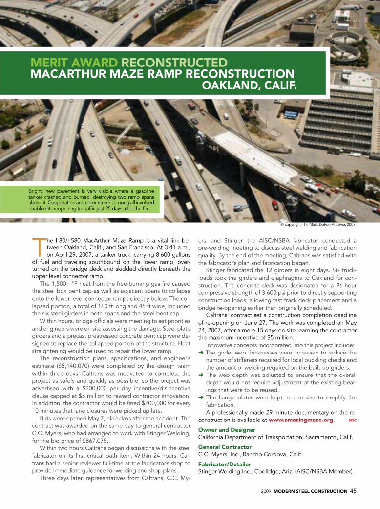
2009 MODERN STEEL CONSTRUCTION 45
The i-80/i-580 MacArthur Maze Ramp is a vital link be-tween oakland, Calif., and San Francisco. At 3:41 a.m., on April 29, 2007, a tanker truck, carrying 8,600 gallons
of fuel and traveling southbound on the lower ramp, over-turned on the bridge deck and skidded directly beneath the upper level connector ramp.
The 1,500+ °F heat from the free-burning gas fire caused the steel box bent cap as well as adjacent spans to collapse onto the lower level connector ramps directly below. The col-lapsed portion, a total of 160 ft long and 45 ft wide, included the six steel girders in both spans and the steel bent cap.
Within hours, bridge officials were meeting to set priorities and engineers were on site assessing the damage. Steel plate girders and a precast prestressed concrete bent cap were de-signed to replace the collapsed portion of the structure. heat straightening would be used to repair the lower ramp.
The reconstruction plans, specifications, and engineer’s estimate ($5,140,070) were completed by the design team within three days. Caltrans was motivated to complete the project as safely and quickly as possible, so the project was advertised with a $200,000 per day incentive/disincentive clause capped at $5 million to reward contractor innovation. in addition, the contractor would be fined $200,000 for every 10 minutes that lane closures were picked up late.
Bids were opened May 7, nine days after the accident. The contract was awarded on the same day to general contractor C.C. Myers, who had arranged to work with Stinger Welding, for the bid price of $867,075.
Within two hours Caltrans began discussions with the steel fabricator on its first critical path item. Within 24 hours, Cal-trans had a senior reviewer full-time at the fabricator’s shop to provide immediate guidance for welding and shop plans.
Three days later, representatives from Caltrans, C.C. My-
ers, and Stinger, the AiSC/NSBA fabricator, conducted a pre-welding meeting to discuss steel welding and fabrication quality. By the end of the meeting, Caltrans was satisfied with the fabricator’s plan and fabrication began.
Stinger fabricated the 12 girders in eight days. Six truck-loads took the girders and diaphragms to oakland for con-struction. The concrete deck was designated for a 96-hour compressive strength of 3,600 psi prior to directly supporting construction loads, allowing fast track deck placement and a bridge re-opening earlier than originally scheduled.
Caltrans’ contract set a construction completion deadline of re-opening on June 27. The work was completed on May 24, 2007, after a mere 15 days on site, earning the contractor the maximum incentive of $5 million.
innovative concepts incorporated into this project include:➜ The girder web thicknesses were increased to reduce the
number of stiffeners required for local buckling checks and the amount of welding required on the built-up girders.
➜ The web depth was adjusted to ensure that the overall depth would not require adjustment of the existing bear-ings that were to be reused.
➜ The flange plates were kept to one size to simplify the fabrication. A professionally made 29-minute documentary on the re-
construction is available at www.amazingmaze.org.
Owner and DesignerCalifornia Department of Transportation, Sacramento, Calif.
general ContractorC.C. Myers, inc., Rancho Cordova, Calif.
Fabricator/DetailerStinger Welding inc., Coolidge, Ariz. (AiSC/NSBA Member)
MERIT aWaRD RECONSTRUCTED
MaCaRThUR MaZE RaMp RECONSTRUCTION OakLaND, CaLIF.
© copyright The Mark DeFeo Archives 2007
Bright, new pavement is very visible where a gasoline tanker crashed and burned, destroying two ramp spans above it. Cooperation and commitment among all involved enabled its reopening to traffic just 25 days after the fire.
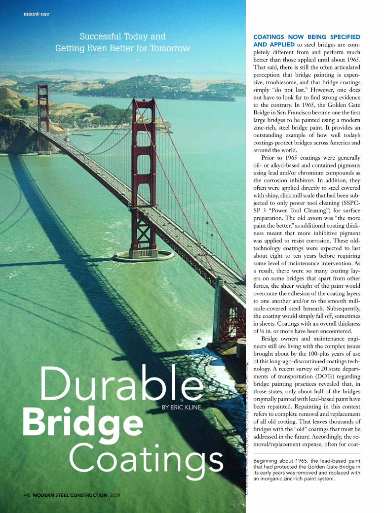
46 MODERN STEEL CONSTRUCTION 2009
COaTINgS NOW bEINg SpECIFIED aND appLIED to steel bridges are com-pletely different from and perform much better than those applied until about 1965. That said, there is still the often articulated perception that bridge painting is expen-sive, troublesome, and that bridge coatings simply “do not last.” However, one does not have to look far to find strong evidence to the contrary. In 1965, the Golden Gate Bridge in San Francisco became one the first large bridges to be painted using a modern zinc-rich, steel bridge paint. It provides an outstanding example of how well today’s coatings protect bridges across America and around the world.
Prior to 1965 coatings were generally oil- or alkyd-based and contained pigments using lead and/or chromium compounds as the corrosion inhibitors. In addition, they often were applied directly to steel covered with shiny, slick mill scale that had been sub-jected to only power tool cleaning (SSPC-SP 3 “Power Tool Cleaning”) for surface preparation. The old axiom was “the more paint the better,” as additional coating thick-ness meant that more inhibitive pigment was applied to resist corrosion. These old-technology coatings were expected to last about eight to ten years before requiring some level of maintenance intervention. As a result, there were so many coating lay-ers on some bridges that apart from other forces, the sheer weight of the paint would overcome the adhesion of the coating layers to one another and/or to the smooth mill-scale-covered steel beneath. Subsequently, the coating would simply fall off, sometimes in sheets. Coatings with an overall thickness of ¼ in. or more have been encountered.
Bridge owners and maintenance engi-neers still are living with the complex issues brought about by the 100-plus years of use of this long-ago-discontinued coatings tech-nology. A recent survey of 20 state depart-ments of transportation (DOTs) regarding bridge painting practices revealed that, in those states, only about half of the bridges originally painted with lead-based paint have been repainted. Repainting in this context refers to complete removal and replacement of all old coating. That leaves thousands of bridges with the “old” coatings that must be addressed in the future. Accordingly, the re-moval/replacement expense, often for coat-
Durablebridge
Coatings46 MODERN STEEL CONSTRUCTION 2009
Successful Today and Getting Even Better for Tomorrow
BY eRiC kliNe
mixed-use
Beginning about 1965, the lead-based paint that had protected the golden gate Bridge in its early years was removed and replaced with an inorganic zinc-rich paint system.
Photo used w
ith perm
ission from g
olden g
ate Brid
ge, w
ww
.gold
engate.org

2009 MODERN STEEL CONSTRUCTION 47
When the zinc is depleted, the steel will eventually rust. Therefore one important consideration is how long the zinc will last. The time it takes for zinc to be consumed is affected by many variables, e.g., weather, duration of wetness, the number of wet/dry cycles encountered, etc. The service life of zinc-coated items often is measured in decades. In a recent article, the American Galvanizers Association (AGA) projected that hot-dipped galvanized (HDG) items will last 75 to 100 years in an aggressive marine environment.
There are a number of important dif-ferences between zinc-rich coatings and galvanizing. In zinc-rich paint part of the coating consists of binder materials where-as galvanizing is 100% zinc. The AGA data for HDG are based on a bare zinc coat-ing. A plus factor in terms of service life for zinc-rich coatings is that they are often paired with additional coating layers (top-coats). These additional layers protect the zinc by limiting the amount of moisture and oxygen in direct contact with the zinc. The extensive and impressive 40-plus-year field performance history of zinc-rich coat-ings, in combination with the AGA calcula-tions, suggests strongly that steel which has been properly coated with a zinc coating and which has additional coating layers can
provide permanent or nearly permanent protection for the steel beneath.
The gold StandardThe current “gold standard” for bridge
coating entails the use of a three-coat sys-tem consisting of an inorganic zinc-rich primer, an epoxy midcoat, and a urethane topcoat (IOZ/E/U). Literally thousands of steel bridges constructed since about 1965 are coated with a zinc-rich primer paint as a part of a paint system and are in excel-lent condition.
One such structure is the world famous Golden Gate Bridge (GGB). This struc-ture measures 8,981 ft long (1.7 miles), weighs about 887,000 tons, has two mas-sive towers that stand 746 ft-tall and a roadway about 220 ft above the Golden Gate Strait. When the bridge was built, from 1933 to 1937, it was coated with lead-based paint. Through an extensive undertaking from 1965 to 1995, the lead paint was removed and an inorganic zinc-rich paint system was applied.
Some areas on the north end of this iconic suspension bridge structure were primed with IOZ, but never topcoated. These areas were recently examined and were in very good condition. According to Dennis Dellarocca, the bridge’s paint
ings containing lead, will continue in many states. In many areas, the current cost is around $12 per sq. ft of steel surface area, including access, lead removal, containment, worker protection, disposal, repainting, etc.
Modern Era TechnologyThere is good news for the owners of
the bridges built or repainted with modern-era coatings, meaning those made available since about 1965. Around that time, many DOTs began specifying the use of blast cleaning to a near white condition (SSPC-SP 10) in order to completely remove mill scale. They also began applying a “new generation” primer.
The coatings introduced at that time employed an entirely different technology than earlier products. They contained me-tallic zinc powder as the pigment providing corrosion resistance. Why zinc? When zinc and iron (or steel) are joined in presence of moisture and oxygen (air)—a corrosive environment—zinc will be consumed first, and the iron (and steel) will be protected from corrosion. This consumption of the zinc will continue until the available zinc is depleted.
The innate ability of zinc to protect steel from corrosion is referred to as “galvanic” protection. This provides long-lasting pro-tection because the zinc reaction normally occurs at a fraction of the rate of corrosion of bare steel in the same environment.Many everyday items are galvanized, including fencing, guard rails, sign structures, light standards, and even automobile parts.
Basically, zinc can be applied to steel in three ways. Galvanizing is a process in which the bare piece of steel is dipped in molten zinc. It is limited by the size of the “kettle” in which the article is immersed. Metallizing requires melting wire contain-ing zinc and spraying the molten metal onto the steel surface, with a stream of air. Both galvanizing and metallizing are excel-lent means of protecting steel from corro-sion. However, many steel bridge members and components are best protected by the use of zinc-rich paint, which is the focus of this article.
Service Life of ZincThe metallic zinc pigment in zinc-rich
paint is able to provide galvanic protection for the steel until the zinc itself is consumed.
Eric Kline is part of the management team at KTA-Tator, Inc., Pittsburgh, Pa. He received a B.S. in Chemistry from Ursinus College, Collegeville, Pa., an MBA from the Uni-versity of Pittsburgh, and is an SSPC Certified Protective Coatings Specialist. He has been involved in the coating, both shop and field, of literally all types of industrial structures. Mr. Kline is a member of SSPC: The Society for Protective Coatings (chairman, co-chairman, or past chairman of sev-eral committees), NACE International, and others. He was the general chairman of the 2008 International Bridge Con-ference (IBC) and also serves on its executive committee.
Four decades after being primed with the inorganic zinc-rich paint but never topcoated, these members on the north end of the bridge continue to be in very good condition.
Photo used with permission from golden gate Bridge, www.goldengate.org
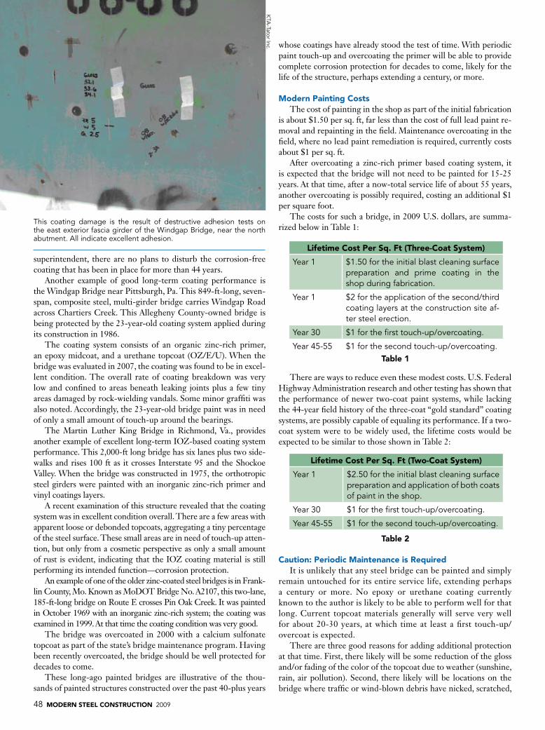
48 MODERN STEEL CONSTRUCTION 2009
whose coatings have already stood the test of time. With periodic paint touch-up and overcoating the primer will be able to provide complete corrosion protection for decades to come, likely for the life of the structure, perhaps extending a century, or more.
Modern painting CostsThe cost of painting in the shop as part of the initial fabrication
is about $1.50 per sq. ft, far less than the cost of full lead paint re-moval and repainting in the field. Maintenance overcoating in the field, where no lead paint remediation is required, currently costs about $1 per sq. ft.
After overcoating a zinc-rich primer based coating system, it is expected that the bridge will not need to be painted for 15-25 years. At that time, after a now-total service life of about 55 years, another overcoating is possibly required, costing an additional $1 per square foot.
The costs for such a bridge, in 2009 U.S. dollars, are summa-rized below in Table 1:
There are ways to reduce even these modest costs. U.S. Federal Highway Administration research and other testing has shown that the performance of newer two-coat paint systems, while lacking the 44-year field history of the three-coat “gold standard” coating systems, are possibly capable of equaling its performance. If a two-coat system were to be widely used, the lifetime costs would be expected to be similar to those shown in Table 2:
Caution: periodic Maintenance is RequiredIt is unlikely that any steel bridge can be painted and simply
remain untouched for its entire service life, extending perhaps a century or more. No epoxy or urethane coating currently known to the author is likely to be able to perform well for that long. Current topcoat materials generally will serve very well for about 20-30 years, at which time at least a first touch-up/overcoat is expected.
There are three good reasons for adding additional protection at that time. First, there likely will be some reduction of the gloss and/or fading of the color of the topcoat due to weather (sunshine, rain, air pollution). Second, there likely will be locations on the bridge where traffic or wind-blown debris have nicked, scratched,
superintendent, there are no plans to disturb the corrosion-free coating that has been in place for more than 44 years.
Another example of good long-term coating performance is the Windgap Bridge near Pittsburgh, Pa. This 849-ft-long, seven-span, composite steel, multi-girder bridge carries Windgap Road across Chartiers Creek. This Allegheny County-owned bridge is being protected by the 23-year-old coating system applied during its construction in 1986.
The coating system consists of an organic zinc-rich primer, an epoxy midcoat, and a urethane topcoat (OZ/E/U). When the bridge was evaluated in 2007, the coating was found to be in excel-lent condition. The overall rate of coating breakdown was very low and confined to areas beneath leaking joints plus a few tiny areas damaged by rock-wielding vandals. Some minor graffiti was also noted. Accordingly, the 23-year-old bridge paint was in need of only a small amount of touch-up around the bearings.
The Martin Luther King Bridge in Richmond, Va., provides another example of excellent long-term IOZ-based coating system performance. This 2,000-ft long bridge has six lanes plus two side-walks and rises 100 ft as it crosses Interstate 95 and the Shockoe Valley. When the bridge was constructed in 1975, the orthotropic steel girders were painted with an inorganic zinc-rich primer and vinyl coatings layers.
A recent examination of this structure revealed that the coating system was in excellent condition overall. There are a few areas with apparent loose or debonded topcoats, aggregating a tiny percentage of the steel surface. These small areas are in need of touch-up atten-tion, but only from a cosmetic perspective as only a small amount of rust is evident, indicating that the IOZ coating material is still performing its intended function—corrosion protection.
An example of one of the older zinc-coated steel bridges is in Frank-lin County, Mo. Known as MoDOT Bridge No. A2107, this two-lane, 185-ft-long bridge on Route E crosses Pin Oak Creek. It was painted in October 1969 with an inorganic zinc-rich system; the coating was examined in 1999. At that time the coating condition was very good.
The bridge was overcoated in 2000 with a calcium sulfonate topcoat as part of the state’s bridge maintenance program. Having been recently overcoated, the bridge should be well protected for decades to come.
These long-ago painted bridges are illustrative of the thou-sands of painted structures constructed over the past 40-plus years
Lifetime Cost per Sq. Ft (Three-Coat System)
Year 1 $1.50 for the initial blast cleaning surface preparation and prime coating in the shop during fabrication.
Year 1 $2 for the application of the second/third coating layers at the construction site af-ter steel erection.
Year 30 $1 for the first touch-up/overcoating.
Year 45-55 $1 for the second touch-up/overcoating.
Lifetime Cost per Sq. Ft (Two-Coat System)
Year 1 $2.50 for the initial blast cleaning surface preparation and application of both coats of paint in the shop.
Year 30 $1 for the first touch-up/overcoating.
Year 45-55 $1 for the second touch-up/overcoating.
This coating damage is the result of destructive adhesion tests on the east exterior fascia girder of the Windgap Bridge, near the north abutment. All indicate excellent adhesion.
kTA
-Tator inc.
Table 1
Table 2

2009 MODERN STEEL CONSTRUCTION 49
or otherwise damaged the coating. Finally, girders and bearings be-neath leaking joints often are bathed in corrosive salt-laden water from storms or from winter deicing activities.
During the touch-up/overcoating operation, all such locations can be repaired and the entire structure can then be completely overcoated. In this scenario the zinc-rich coating, which provides the basic corrosion protection, is not disturbed in the repair/overcoat-ing process. Consequently, the zinc layer will remain beneath the existing coating and any new coating(s) applied during the touch-up/overcoating process. It is expected that this zinc-rich paint layer should be able to perform its corrosion resistance function for the life of the structure.
Note that other very good zinc-rich primer coating systems cur-rently are available, and widely used, in addition to the IOZ/E/U system discussed above; however, it is that “gold standard” system that already has stood the test of time, since at least 1965, and is widely specified and successfully used.
Rapid DeploymentTwo areas of technology have been developed in recent years
to assist in field cleaning and repainting low-rise overpass bridges located in high traffic areas that cannot be shut down for long pe-riods. These practices, dubbed “rapid deployment,” involve the use of mobile, blast cleaning equipment and containment platforms—usually flat-bed trailer mounted—that are used to completely en-close the area to be cleaned and painted. The mobile platform can be deployed overnight to enable cleaning and painting to occur. The trailer is removed from the roadway before rush hour begins the next morning.
The second aspect of a rapid deployment approach is the use of a matching two-coat coating system consisting of a fast-curing or-ganic zinc-rich primer along with a fast-curing high-build topcoat. Using this tandem approach allows the contractor to mobilize the platform, clean an area and apply both coating layers in an over-night shift, thereby completing the work on that area. Economies associated with rapid deployment are readily apparent.
Coatings prequalificationIn days gone by, the myriad vendors in the coatings industry
offered the bridge engineering community many materials. Each state was forced to provide its own prequalification test program and to develop and maintain a qualified products list (QPL). Test-ing by every state was expensive and duplicative.
Since then standard test protocols have been developed under the auspices of the AASHTO National Testing Product Evaluation Program (NTPEP). Suppliers of coatings to the bridge painting in-dustry are now required to have their products tested in accordance with the AASHTO NTPEP testing standard for Structural Steel Coatings (SSC). In these laboratory “torture tests,” the performance of candidate bridge coating systems is evaluated using tests identical to those required to qualify the IOZ/E/U system described above.
Test results are accumulated in the AASHTO DataMine which is available to state DOTs for the purpose of coating system com-parison. Each state can apply its own performance criteria. For ex-ample, a state with a mild, less-corrosive environment may have different criteria for adding a coating system to its QPL. Informa-tion about the AASHTO NTPEP coating testing program can be found online at http://www.ntpep.org/ContentManagement/PageBody.asp?PAGE_ID=30.
This 1999 photo shows the excellent condition of the inorganic zinc-rich coating on bridge A2107 in Missouri 30 years after its application.
Tom Calzone
The New England states also have their own separate prequali-fication testing standard by which materials are prequalified and listed on a QPL accepted by the member states and several others. The NEPCOAT member states are: Connecticut, Massachusetts, Maine, New Hampshire, New Jersey, New York, Pennsylvania, Rhode Island, and Vermont. The NEPCOAT Qualified Prod-ucts Lists can be found online at http://www.state.me.us/mdot/nepcoat/qualprod.htm. Approved two-coat systems like that dis-cussed above for rapid deployment are presented in NEPCOAT Appendix C.
Many states use either/or the AASHTO DataMine or NEP-COAT for coating performance data. See http://www.state.me.us/mdot/nepcoat/.
ConclusionBridge engineers are properly cautious professionals who are
charged with safely building and protecting our modern infrastruc-ture from attacks of all kinds, including corrosion. For nearly a cen-tury following construction of the Eads Bridge in St. Louis, which heralded the beginning of the steel bridge era, bridge engineers did the best they could to protect steel bridges with various coatings systems. Since the advent of the modern age of bridge coatings, in 1965, many improved user-friendly, color-retentive, adherent, corrosion-preventing and durable coatings have emerged from the coatings industry. Literally thousands of improvements have been made in every aspect of bridge paint and painting leading to im-proved durability.
Effective means of corrosion protection via corrosion preven-tive protective coatings have proved themselves in the field for more than 44 years. Progress is steadily being made toward the develop-ment of even better, more durable, safer, and more cost-effective coatings, ensuring that there always is a solution in steel.

50 MODERN STEEL CONSTRUCTION 2009
T
Steel girders
BY AhMAD ABu-hAWASh, P.e., AND huSSeiN khAlil, P.e.
ThE FIRST CONSTRUCTION pROjECT completed under the Council Bluff’s (Iowa) Interstate System (CBIS) improvement project was the 24th Street interchange, which crosses the over-lapping segments of I-80 and I-29. As an important arterial serv-ing major attractions and businesses such as casinos, a conference/event center, hotels and large shopping outlets, it was essential to maintain three lanes of traffic—one in each direction, plus a turn-ing lane—throughout construction.
Projects of this scope typically are constructed over two con-secutive construction seasons, but the critical location of this in-terchange required limiting traffic restrictions on 24th Street to a single season (April thru October). Maintaining traffic flow and the accelerated construction schedule became the driving forces in the structure’s design.
Fortunately, with the help of the Federal Highway Adminis-tration’s Highway for Life (HfL) initiative and Innovative Bridge Research and Deployment (IBRD) program, Iowa Department of Transportation used innovations that are new to Iowa but already proven to meet the needs of the traveling public during and after construction. The HfL and IBRD programs accelerated construc-tion while maintaining traffic access, reducing future maintenance and improving safety both during and after construction.
The Steel SolutionSeveral bridge types and construction phasing options were con-
sidered to best meet design and safety standards, facilitate traffic and minimize right-of-way impacts. The existing four-span, 216-ft-long by 64-ft-wide prestressed concrete beam bridge spanned five inter-
N A T i o N A l S T e e l B R i D g e A l l i A N C e NEWSSteel BridgeDeCeMBeR 2009
Construction StagingBridgeSupport

2009 MODERN STEEL CONSTRUCTION 51
state traffic lanes, but the proposed bridge needed to accommodate future interstate expansion to a 12-lane dual-divided roadway sec-tion and a centerline shift of approximately 42 ft.
Shifting the I-29/I-80 centerline factored significantly into the de-sign because it defined the location of the center pier. Interstate traffic beneath the bridge had to be maintained between existing piers and the proposed center pier during the first phase of construction. Add-ing more piers to reduce span lengths was not feasible when consider-ing existing, staged and proposed roadway configurations.
The solution was a two-span, 354-ft-long by 105-ft-wide bridge with welded plate high performance steel (HPS) girders support-ing full-depth post-tensioned deck panels. Steel girders were the most feasible option considering the required span lengths of 178.5 ft and 175 ft exceeded Iowa DOT’s prestressed concrete
beam standards. Longer spans accommodated the interstate final lane configurations and allowed the flexibility to stage interstate traffic without reducing the number of lanes. Furthermore, the contractor could choose whether to install the shear connectors after deck placement, which afforded the opportunity to make any needed adjustments. The final design featured 12 lines of steel girders spaced 9 ft on-center with a maximum length between field splices of 121.75 ft.
Constraints on vertical profiles required a shallower than op-timum girder depth, which also favored the choice of HPS gird-ers. The designer determined the use of higher strength material for the bottom flange and the top flange between the two field splices of the pier section to be the most economical. HPS 70W steel was selected for these areas based on its higher strength
Using longer spans and stronger steel made the 24th Street Bridge a one-season project.
Ahmad Abu-Hawash, P.E. (left), is the chief structural engineer with the Iowa Department of Transportation where he has been involved in construction and bridge design for more than 20 years. Hussein Khalil, P.E., is a se-nior professional associate and vice president with HDR Inc. in Omaha, Neb. In addition to 25 years of practical experience, he also has research experience dealing with accelerated construction.
Opposite page: The existing 24th Street Bridge spanned five interstate traffic lanes, but the new bridge will accommodate future interstate expan-sion to a 12-lane dual-divided roadway section and shift the centerline approximately 42 ft.
above: Alignment and clearances dictated a shallower than optimum girder depth, prompting the use of higher strength material for the bottom flange as well as the top flange between the two field splices of the pier section.
Photos these pag
es by k
eith Philpott

52 MODERN STEEL CONSTRUCTION 2009
hD
R in
c.
Allowing the contractor to install the shear studs in the field rather than having them in-stalled in the shop as is traditionally done with cast-in-place decks provided greater tolerance for the erection of the deck panels and facili-tated their placement.
coupled with improved toughness and durability. All other steel, including the web, was specified to be A709, Grade 50. The web thickness of 0.5 in. required no intermediate stiffeners in the positive mo-ment regions and a minimal number in the negative moment zones. Cross-frame diaphragms consisted of two angle cross braces between two WT-shaped top and bottom struts generally spaced at 22 ft. A plate diaphragm was specified between the two phases of construction with one set of girder holes for Phase 1 to be drilled and connected after the Phase 2 superstruc-ture was completed and most of the dead load applied.
Working TogetherBecause the steel girders were designed
to act compositely with the deck, the gird-ers and deck were joined together using shear connectors. Shear studs grouped together maximized the economy of deck panel fabrication and provided the neces-sary composite action. In addition, the plans allowed the contractor to install the shear studs in the field rather than having them installed in the shop as is traditionally done with cast-in-place decks. Again, in-corporating an on-site installation method
into the design provided greater tolerance for the erection of the deck panels and fa-cilitated placing them more quickly.
The cross-section included two lanes in each direction, two turn lanes, a raised me-dian, a raised sidewalk and a raised multi-use trail. Each of the 70 deck panels was fabricated to be 10 ft long by 52 ft 4 in. wide and 8 in. thick, comprising roughly half of the new bridge width. The design made it possible to construct each half in one phase, then join the two halves of the completed deck using a longitudinal closure pour. To improve ridability and provide an addition-al level of protection for the post-tensioned deck system, the panels were topped with a high-density overlay.
Each panel was pretensioned in the transverse direction with ten, 0.5-in.-diameter, 270-ksi low relaxation strands at the top and ten, 0.5-in.-diameter, low-relaxation strands at the bottom of the panels. A total of 28 flat ducts embedded in each panel housed the longitudinal post-tensioning. Four 0.6-in.-diameter, low re-laxation, 270-ksi strands were installed in each of the embedded ducts. Pockets in the panels accommodated the headed shear studs. Designing Phase 1 panels to be geo-metrically similar to Phase 2 panels pro-
vided economy of fabrication.The deck panels were installed after
the steel framing was erected and the slab buildup below the deck panels was formed. Slab build-up forming methods and level-ing the panels to the correct elevation were left up to the contractor; however, the plans included optional leveling bolts embedded in the deck panels that could be used by the contractor to aid in setting the panels to the correct elevations. After all the deck panels for a phase were erected, the trans-verse joints were filled with high-strength, non-shrinking grout.
The 24th Street Bridge used female-to-female transverse joints between panels, eliminating the need for match casting and reducing the risk of damaging panel edges during erection and post-tensioning. Expe-rience with other projects showed that this type of joint tended to perform better than alternative joints, especially where longi-tudinal post-tensioning was utilized. The transverse joint configuration in the panels was a very important aspect to the design and successful service life of the structure. A poor detail of the transverse joint could result in leakage of the joint material and spalling adjacent to the joint.
Coordination among the designer, the

2009 MODERN STEEL CONSTRUCTION 53
Eliminating Congestion in StagesThe 75,000 vehicles that travel interstate 80 through Council Bluffs, iowa, on a typical day represent more than double the estimated traffic flow when the roadway was designed and constructed in the 1960s. With its ca-pacity already stretched, the highway is ex-pected to see daily totals climb to more than 120,000 in the next 20 years. Similarly, the 20,000 drivers using i-29, which interchanges and overlaps i-80 in Council Bluffs, is project-ed to double over the next two decades.in response to the safety, congestion and capacity concerns created by the i-80/i-29 corridor’s popularity, the iowa Department of Transportation (DoT) initiated the Council Bluffs interstate System (CBiS) improvements project. The project encompasses 18 miles of interstate highway in Council Bluffs and the eastern portion of omaha, Neb., and af-fects 11 interstate-to-local road interchanges as well as three interstate-to-interstate inter-changes. To help manage the magnitude of work, the overall project is organized into five adjacent segments. More information is avail-able at www.iowadot.gov/cbinterstate/.
owner, local contractors and fabricators were key to developing an economical design for this project while also reducing future maintenance. Using accelerated construction techniques and innovative construction methods made it possible to maintain traffic access and improve safety during and after construction, and incorporating high-performance steel girders into the design made it possible to complete the project within a single construction season.
The authors would like to thank Norm Mc-Donald, P.E., James Nelson, P.E., and Kimball Olson, of the Iowa Department of Transporta-tion; Brent Phares, P.E., of Iowa State Univer-sity and Phil Rossbach, P.E., of HDR Inc., for their contributions to this article.
Owneriowa Department of Transportation
Structural EngineerhDR inc., omaha, Neb.
general ContractorCramer & Associates inc., grimes, iowa

54 MODERN STEEL CONSTRUCTION 2009
TAvoiding the need for several
pesky permits also allowed the project to start much earlier.
ThE NOOkSaCk RIVER CROSSINg is part of a widening project for Washington State Route 539. This section of highway is being converted from one lane each way to a four-lane divided highway. The river crossing is located near the town of Lynden, approximate-ly six miles south of a border crossing to British Columbia.
The site provided numerous challenges. The foundation mate-rial is extremely poor, and the height of the roadway embankment is limited by settlement and existing profile grade. The superstruc-ture depth was limited to about 6 ft based on clearance to high wa-ter. Environmental permitting restricted placement of piers within the river channel.
These site challenges dictated a clear span of about 340 ft, leav-ing the only reasonable option a truss to match the existing bridge. The right-of-way was extremely limited, and construction access would require a lengthy permitting process. It was anticipated ob-taining permits for construction access within the river channel would take at least a year. Also, the river is too low during the construction season for barge cranes.
The design called for a truss span of 350 ft, with a roadway width of 40 ft. A cantilever method of construction was proposed to cir-cumvent the year of permitting. Two configurations were considered in the preliminary planning phase: a three-span truss and a single-span truss with two concrete approach spans. The second option was
selected to better match existing conditions. The concrete approach spans were to be used as anchors for a backstay system. This became a balancing act during design, because it was discovered that construc-tion access for large land-based cranes was not available on the south shore. Tower cranes were cost-prohibitive for this application.
The backstay system, therefore, needed to accommodate crane access and weight, in addition to truss self weight. Fortunately, the approach spans provided enough counterweight. A launch-ing option was studied, but the necessary apparatus was quickly determined to be much more cumbersome by comparison. The three-span construction option would have been patterned after a number of Columbia River crossings, albeit at a smaller scale. Very little modification was needed for truss member design based on the cantilever method of construction.
The contract included complete details for the backstay sys-tem, including attachments to the truss and anchorage to the ap-proach spans, which is not common practice for a WSDOT de-sign-bid-build contract. The usual WSDOT method is to ensure constructability and provide schematic construction information only, allowing a contractor to build as suited. The contract did al-low for a contractor-designed system, but Max J. Kuney chose to erect the steel using the details provided, with modest changes in the jacking arrangement.
BY NAThAN BRoWN, P.e., S.e.
The CantileverTrussShortcut
lyle Jansma, Jansma Design
steel bridge news NATioNAl STeel BRiDge AlliANCe

2009 MODERN STEEL CONSTRUCTION 55
The plans called for the truss to be assembled in the shop or yard to verify and record geometrics as-fabricated. The intent was to have a way to monitor geometry during fit-up in the field and make closure at midspan less prone to mismatch.
Procedures for closing and releasing the span were shown in the plans. Temporary construction pins were used in the last truss members installed to quickly provide joints with adequate strength and mobility. Once the truss halves were joined and geometry fixed, these last con-nections would be bolted. The plans called for closing the truss during stable thermal conditions, to avoid harmful movement of the steel.
Fortunately, a typical Puget Sound rainy day arrived when the time came to drive construction pins at midspan. Temperature dur-ing closure did not vary by more than a degree. After the truss connections were complete, jacks at thrust blocks and backstay an-chorages were used to release the support system. These jacks were incorporated into the scheme for adjusting elevations and advanc-ing or retracting the cantilevers at closure.
The contractor estimated it took an additional month to erect the steel, compared to using conventional shoring and work trestle. The steel erector thought it took closer to two months additional time. The crane access decking turned out to be tedious and time consuming to install and move. Also, there was down time waiting for completion of the north approach. Truss erection began in ear-ly May, and was completed by mid-September. All parties still favor conventional, contractor designed methods for erecting steel.
The steel fabricator proposed and used a less involved shop as-sembly. The truss was completed without the need to modify mem-bers or connections. Shop drawings for the bridge were created with Tekla 3D modeling software, to ensure proper fit-up. Gusset plates and splice plates were drilled on CNC drilling equipment using the downloaded Tekla data in order to maintain hole tolerances. Because most structural members were fabricated during the winter months, extra care was taken to maintain tolerances due to expansion and contraction as the temperature changed. Built up box members were welded in lengths longer than required due to some shrinkage in length of the member during welding. The members were then cut to length in Rainier Welding’s environmentally controlled building, in order to maintain length tolerance.
The truss design was patterned after the Cooper River truss in South Carolina (see Modern Steel Construction October, 1996). The Nooksack River truss will have the same open appearance when complete. The usual portal and sway frames are absent, providing much higher vertical clearance from traffic.
The finished bridge consists of 705 tons of structural steel with an associated cost of $5.172 million, which includes a three-coat paint system and special erection. The roadway deck is expected to be completed late this year.
Owner/DesignerWashington State Department of Transportation
ContractorMax J. kuney, Spokane, Wash.
FabricatorRainier Welding, Redmond, Wash. (AiSC Member)
ErectorSchneider up, olympia, Wash. (iMPACT Member)
Opposite page: Cantilevering the new truss out from both sides of the crossing enabled construction to proceed much sooner than if the usual permits for construction access, including those needed to work in the river channel, would have been required.
Nathan Brown, P.E., S.E., began his bridge design career in 1980 and since 1993 has been a steel specialist for the Washington Department of Transpor-tation, Bridge and Structures Office, Tumwater, Wash.
Because access for a large land-based crane was not available on the south shore of the Nooksack River crossing, the anchorage and back-stay system had to support the weight of equipment as well as the truss weight.
Temporary construction pins were used in the last truss members in-stalled to quickly provide joints with adequate strength and mobility. once the truss halves were joined and geometry fixed, the last connec-tions were bolted.

56 MODERN STEEL CONSTRUCTION 2009
IIN 1933 aN EIghT-SpaN reinforced concrete spandrel arch was constructed to carry traffic on Kan.sas Highway 1 (now U.S. Highway 183) over the Saline River, north of Hays, Kan. In the intervening years, migration of the upstream section of the Sa-line changed the river’s angle of attack on the piers of the existing bridge, resulting in scouring at its spread footings. Current road design standards require a wider roadway and although the span-drel arch possesses a stately profile, that type of structure is not easily or economically widened. A new bridge with modern, scour resistant, deep foundations was required.
The Kansas Department of Transportation decided this project would provide a good test of the viability of using post-tensioned, prestressed concrete girders compared to traditional steel plate girders. The requirement was for a bridge of moderate length (about 660 ft) and the site had room for construction staging. The location also was readily accessible to contractors in Nebraska and Colorado with post-tension construction experience.
Two designs were prepared for letting: a four-span (140-ft, 187-ft,187-ft, 140-ft) steel plate girder design by the in-house de-sign staff of KDOT’s Bridge Office and a four-span post-tensioned prestressed concrete girder design, with spans nearly identical to the steel design, by an experienced consultant. Though both de-signs carried the same 44-ft roadway, the superstructure and sub-structure of each design was unique.
The plate girders were designed to act compositely with the con-crete and have a uniform web depth of 75 in. Grade 50 weathering steel was used with AASHTO M270 T3 certification called out for the flange material. This was one of the first structures erected using Kansas’ Special Provision requiring that specific and detailed erec-tion plans be provided to the engineer on site. This provision was formulated in consultation with the Kansas Contractors Association
after multiple steel and prestressed concrete girder erection prob-lems. At a minimum, the provision requires the approval of erection plans by the state and the use of a pre-qualified erection supervisor.
The design for the post-tensioned prestressed concrete girder option used 73-in.-deep modified Kansas K6+1 beams. The girder spacing was slightly wider than that used in the steel girder option (9 ft, 6 in. vs. 8 ft, 2 in.), resulting in one less girder line. The maxi-mum piece length of the concrete girders was limited to 150 ft to facilitate shipping, requiring erection of the girders to be a multi-stage process using strong backs at the girder splice locations on both sides of the center pier and a falsework tower in span three. Post-tensioning was to have been in two phases, one before and one after placement of the concrete deck.
The greater weight of the concrete girders required more sub-stantial foundation elements than the steel alternative. The design of the steel alternative required nine H-piles per abutment, as op-posed to 11 of the same size pile for the concrete alternative. The steel bridge uses three 66-in. drilled shafts per pier as opposed to three 72-in. drilled shafts per pier for the concrete alternate.
The engineer’s cost estimates for the steel bridge and the post-tensioned prestressed concrete bridges were both around $3 mil-lion, but a true comparison of the costs between the structure types is unavailable. When the project was bid in 2008, all four bidders bid only on the steel alternative.
The new bridge was completed in the summer of 2009. The ex-isting spandrel arch bridge, eligible for placement on the National Register of Historic Places, will be preserved on the old alignment adjacent the new bridge.
Mark Hurt, P.E, S.E., is senior squad leader for bridge design with the Kansas Department of Transportation.
Foundations required for the new steel bridge (right) crossing the Saline River in kansas were somewhat lighter than would have been required if concrete had been used, and far less than those required to support the old reinforced concrete bridge (left).
Simplified construction and reduced foundation requirements make steel
the preferred alternative.
Saline River
A NewCrossing for the
BY MARk huRT, P.e, S.e.
steel bridge news NATioNAl STeel BRiDge AlliANCe

2009 MODERN STEEL CONSTRUCTION 57
The Museum of Flight in Seattle is one of the largest air and space museums in the world, attracting
nearly 500,000 visitors each year. A recent addition to the museum—a symbolic 340-ft pedestrian bridge—helps to better circulate these visitors and also provides an eye-catching icon to the industrial area where the museum is located.
A conventional, utilitarian public works bridge would have been possible but in-adequate to convey the spirit of the muse-um and the area’s aviation history. instead, the design of the bridge is inspired from the metaphor of the contrail, a stream of crystallized vapor created in a plane’s wake. The metaphor is carried out in the bridge’s unusual tube truss design, made of crossing circular steel pipe sections surrounding an inner glass enclosure and culminating in what juror Mike Moravek deemed “a progressive, innovative con-nector to the local heritage.”
The unique structure of the bridge evolved from the design collaboration between SRg Partnership (architect), MkA (structural engineer), and Jesse engineering (steel fabricator). The de-sign team conceived a structural de-sign that did not rely on conventional truss webs, but instead distributed
the vertical shear in the bridge struc-ture through a matrix of curving steel pipes. This exciting and dynamic form had the potential to be overly com-plex and unachievable within the proj-ect budget. however, using standard steel member sizes, constant radius pipe bends, and predetermined “fish-mouth” end cuts, the complex design was fabricated economically.
The main truss, 200 ft long, is made of a series of crossing 5-in.-diameter pipe hoops tilted at 45°. The elliptical cross section swells slightly in the cen-ter, narrowing at its ends to heighten the sense of movement. lightweight materials and a composition of trans-parent, translucent, and metallic surfac-es soften the reflected light, at times appearing to dissolve against the sky.
using a steel truss allowed the structural depth to surround the par-tially enclosed interior space and more successfully reference the language of the existing museum architecture. The bridge uses approximately 10,000 linear ft of steel pipe at a total steel weight of 190 tons. The contrail con-figuration used approximately 151 pieces of tube rolled to different radii, as the bridge was wider at the middle
than the ends (all the pipes were rolled at a constant radius but as the width changes, so does the radius.). Shorter pieces needed to be cut to fit between the full hoops to make the truss that surrounded the main chords, which were made of 10-in.-diameter pipe; the pipes for the chords were pur-chased in 60-ft lengths, then spliced together.
For more on this project, see “Taking Flight” in the December 2008 issue of MSC, available in the Archives section at www.modernsteel.com.
Merit award—Under $15M MUSEUM OF FLIghT, T. EVaNS WyCkOFF MEMORIaL bRIDgE—SEaTTLE
OwnerMuseum of Flight, Seattle
architectSRg Partnership inc., Seattle
Structural EngineerMagnusson klemencic Associates,
Seattle
Steel FabricatorJesse engineering Co., Tacoma, Wash.
(AiSC/NSBA Member)
Steel DetailerMke Detailing, inc., Seattle (AiSC/NiSD
Member)
general ContractorSellen Construction Co., Seattle
innovative connectorA progressive,
to the local heritage.—Mike Moravek
”
“
photos by lara Swimmer Photography
awards

58 MODERN STEEL CONSTRUCTION 2009
The Buy America and Buy American Acts appear to promote domestically produced steel, but loopholes in both allow for other shopping destinations.
government affairs
BY ANgelA R. STePheNS
Made in
1 41 U.S.C. §§10a -10d.
2 23 U.S.C.S. §313 and 23 C.F.R. 635.410.
3 23 C.F.R. 635.410(b)(1-4).
AaS ThIS aRTICLE gOES TO pRESS, more details of the Obama administration’s 2009 Economic Stimulus Package are being re-leased. Common wisdom is that, when complete, the Stimulus Package will include a public works component to fund construc-tion and renovation of bridges, highways, and public buildings from the federal level down to local school districts. Included in the stated goals for building construction are increased energy ef-ficiency and sustainability.
The rationale accompanying the Economic Stimulus Package emphasizes the “three P’s”: (1) Put money into the economy; (2) Put Americans back to work; and (3) Provide needed infrastruc-ture upgrades (transportation, heavy civil/utility, and building con-struction). Sadly, under the current federal law there is no guaran-tee that American funds applied to rebuild the infrastructure will be paid to American workers or American companies. Under the interpretation of the current law there is every possibility that for-eign mill steel and foreign fabricated steel could find its way into public works projects funded by the 2009 Stimulus Package. It is clear that most Americans are not aware of the loopholes in the current law. At this writing it is still unclear whether our legislators will take the action necessary to close those loopholes.
There are two separate “domestic only” provisions applicable to federal construction projects. On the surface, these provisions require using American materials. One set of provisions applies to bridge construction and is contained in the Federal Highway Ad-ministration (FHWA) and Federal Transit Administration (FTA) Buy America statutes, which, in turn, are derived from the Surface Transportation Assistance Act of 1982. The other set of provisions is contained in the Buy American Act, and applies to non-transpor-tation federal construction projects.1 (Note the subtle difference:
“Buy America” for bridges and “Buy American” for buildings.)
In application, neither guarantees that American public works projects will be built exclusively with American material and American labor.
bridge ConstructionThe current FHWA and FTA Buy America provisions were
enacted 1978 when Congress sought to expand domestic procure-ment coverage to the federally funded highway construction proj-ects. The Buy America provisions provide that federal-aid funds may not be used on federal-aid highway construction projects un-less the iron and steel used on the projects are manufactured in America.
FhWa buy america Statute and RegulationsThe Federal Highway Administration Buy America statute
and regulations apply to federally funded FHWA projects.2 Es-sentially, this statute requires that all steel and/or iron materials that are permanently incorporated into a FHWA project must be manufactured and fabricated in the United States. Here is the first loophole: If a state DOT determines that a bridge structure (even a bridge structure that is to remain in place for years and possibly then moved for a secondary, continued use at another location) is temporary rather than permanent in nature, then the Buy America protection does not apply. Then there is a second loophole: Buy America protection does not apply to bridge structures funded to-tally from state revenue, even if application of federal funding to another state highway project freed state funds to be applied to build a bridge through loophole number two.
The FHWA Buy America statute also does not apply if: (1) the State accepts alternate bids from both foreign and domestic steel mills or fabricators and the foreign company’s bid is lower than the domestic company’s bid by more than 25%, or (2) the use of foreign steel and iron does not exceed 0.1% of the total contract value or $2,500, whichever is greater. 3
A state may apply for a waiver of the FHWA Buy America stat-ute if: (1) the application is felt to be inconsistent with the public interest, (2) it is claimed that needed materials and products are not produced in America in sufficient quantity or quality, or (3) the

2009 MODERN STEEL CONSTRUCTION 59
inclusion of domestic material will increase the cost of the overall project by more than 25%. Herein is loophole number three. Does the 25% rule apply to the total cost
of the entire project (in the case of a bridge, the entire span—including approaches—from shore to shore) or can it be applied to separate contracts for individual proj-ect components? Some states have broken bridge projects down into individual com-ponents, contracted separately for those components, and applied the 25% rule only to the individual contract component and not to the project as a whole.
Also, certain trade agreements may waive the applicability of the Buy America statute.
FTa buy america Statute and Regulations
The FTA Buy America statute applies to FTA federal-aid highway construction projects.4 The FTA Buy America statute is substantially similar to the FHWA statute. Of importance, however, is that the FTA Buy America statute provides that a waiver may also be obtained if, when procuring rolling stock, the cost of components and subparts produced in America is more than 60% of the cost of all components of roll-ing stock and the final assembly of the roll-ing stock has occurred in America.
building Construction The Buy American Act (“the Act”) was
enacted in 1933 in an effort to stimulate the domestic economy. It was designed by its drafters as a device “to foster and pro-tect American industry, American work-ers, and American invested capital.”5 It provides that certain American materials, such as steel, must be used on any feder-ally funded construction project where the federal agency makes a direct purchase or awards a contract. (Remember, “Buy Amer-ica” applies to federally funded transporta-tion projects; “Buy American” applies to everything else.)
The Act applies unless: (1) it is inconsis-tent with the public interest, (2) the cost is unreasonable, (3) the material will be used
outside the U.S. (say, an offshore DOD or DOS facility), (4) the material is insufficient and not reasonably available in commercial quantities and of a satisfactory quality, or (5) the contract award value is less than or equal to $2,500. Additionally, trade agree-ments, such as NAFTA and the Trade Agreement Act, waive the requirements of the Buy American Act for construction materials purchased from certain countries if the estimated value of the construction project exceeds certain amounts.
Because of the many waivers and ex-ceptions that have found their way into the Buy American Act, impacting building construction over the years, it has become riddled with loopholes. The Buy American Act notwithstanding, there are many in-stances where federal funds purchase steel from foreign mills and foreign fabricators for domestic federal construction projects.
Objections to EnforcementOver the years proponents of incorpo-
rating foreign steel products into domes-tic public works projects have relied upon a common theme to press for progres-sive weakening or removal of domestic preference provisions in federally funded construction projects. Their argument normally contains the following theme:
“Domestic steel producers and fabricators are not as efficient as their foreign com-petition. They cost too much, they run up the price of public works, and the public has no assurance that they are not hiding behind domestic preference provisions to artificially inflate their prices.”
This argument is strongly contested by the domestic steel industry. Domestic producers and fabricators argue that when competition is fair and grounded on a level, legal playing field (including application of fair and competitive structural design and fair application of international trade laws and environmental considerations) the American steel industry can compete with anyone in the world. Domestic mills and fabrication shops argue that they lead the world in efficiency and have not asked for a penny in government subsidies. Domestic producers consistently ask only for a level playing field.
However, the domestic industry con-tends that the playing field is not level, and that some foreign governments allow their
industries to operate under advantages that are simply not shared by their American competition. All of this can be rectified by our government, and sufficient safeguards (teeth) can be brought to bear by our gov-ernment to safeguard the American public against price gouging.
But rectification of international trade abuses takes time, and, simply stated, the American economy is under stress—and American workers and companies believe that they do not have time to wait for diplo-macy and the international courts to rectify what they perceive as the current imbalance.
added provisionCongress and/or the president have the
inherent authority to strengthen the Domes-tic Preference provisions in federal procure-ment law and/or to temporarily close the current loopholes in the law during periods of national emergency. Participants in the domestic industry claim that we currently find ourselves in a period of national emer-gency and that strong action by government is required to maximize the benefits of the Economic Stimulus Package for American companies and American workers.
Many organizations, like AISC, have passed resolutions and asked members of Congress to include a “domestic only” pro-vision in the 2009 Stimulus Package that would ensure that federal funds are being given to American workers and American companies. You can join these efforts by contacting your member of Congress and ask that he or she supports legislation that will close the loopholes in the current Buy America and Buy American provisions and/or add a “domestic only” provision to any stimulus packages.
Angela R. Stephens is a civil engineer and law-yer with Stites & Harbison, PLLC, counsel to AISC. Angela has concentrated her practice in construction law. She is active in the National Association of Women in Construction (NA-WIC) and will be speaking at the 2009 North American Steel Construction Conference in Phoenix this April. The views expressed here are those of Ms. Stephens and not necessarily those of either AISC or Stites & Harbison.
4 49 U.S.C.S §5323(j) and 49 C.F.R. 661.1 - .21.
5 76 Cong. Rec. 1896 (1933) (remarks of Rep. Eaton), cited in Textron, Inc., Bell Helicopter Textron Division v. Adams, 493 F. Supp. 824, at 830 (D. D. C. 1980).
The buy american act notwith-standing, there are many instanc-es where federal funds purchase steel from foreign mills and for-eign fabricators for domestic fed-eral construction projects.
The buy america act applies to bridges, while the buy american act applies to buildings.

There's always a solution in steel.
American Institute of Steel ConstructionOne East Wacker Drive, Suite 700Chicago, IL 60601
312.670.2400 www.aisc.org
National Steel Bridge AllianceA division of American Institute of Steel Construction
One East Wacker Drive, Suite 700Chicago, IL 60601
312.670.2400 www.steelbridges.org