steam/hot water unit heaters - amazon s3 · application, design, construction overview - all units...
TRANSCRIPT

1-150.11October, 2008
Steam/Hot Water Unit Heaters
MODEL HSB/HC MODEL V/VN
MODEL GLW
MODEL PT/PTN

1-150.11
TaBLE Of CONTENTS
as Modine Manufacturing Company has a continuous product improvement program, it reserves the right to change design and specifications without notice.
C US
®
Table of Contents Page
I. Design Benefits A. Application,Design,ConstructionOverview.............................................3 B. UnitFeatures–HorizontalDeliveryUnitHeaters.....................................4 C. UnitFeatures–VerticalDeliveryUnitHeaters.........................................5 D. UnitFeatures–Power-Throw™HorizontalDeliveryUnitHeaters............5 E. UnitFeatures–LowWaterTemperatureGreenhouseHeatingUnits......6 F. OptionsandAccessories..........................................................................7 G. PowerCodeDescriptions,SoundClassifications,ControlSequence......8
II. Performance Data A. BreezeTMAccuSpecSizingandSelectionProgram..................................9 B. SteamConversionTables.......................................................................10 C. SteamPerformanceData–StandardModels........................................13 D. SteamPerformanceData–LowOutletTemperatureModels................14 E. SteamConversionTables–ExampleCalculations................................15 F. HotWaterConversionTables.................................................................16 G. HotWaterPerformanceData–StandardModels..................................19 H. HotWaterPerformanceData–LowOutletTemperatureModels..........20 I. HotWaterConversionTables–ExampleCalculations..........................21 J. MaximumMountingHeightsforOutletAccessories,Dimensions..........22 K. MotorData,Step-DownTransformerAccessoryData............................23
III. Dimensional Data A. Dimensions–HorizontalAirDeliveryModels.........................................24 B. Dimensions–VerticalAirDeliveryModels.............................................25
IV. Model Identification........................................................................................26
V. Specifications.................................................................................................27
�
Refer to page 9 for information regarding the BreezeTM accuSpec Sizing and Selection Program
Canadian Registered
heat exchangersCRN
OH 9�34.5

1-150.11 3
DESIGN BENEfITS
application, Design, Construction Overview - all Units
Wide Product Selection•Ratingsaslowas11,300Btu/hrforhotwatertoashighas952,000Btu/hrforsteam,basedonstandardconditions.
•Horizontal,Vertical,andPower-Throw™(highvelocityhorizontalairdelivery)modelsoffermaximumapplicationflexibility.
•RatingsareshownasBtu/hr(basedon2PSIsteam,60°Fenteringairconditions),eliminatingtheneedtoconvertfromEDR.Thissimplifiesthematchingofunitratingstobuildingheatloss.
application flexibility
•HorizontalandPower-Throw™unitsarefurnishedwithlouversfordirectionalcontrolofheatedair.Verticalunitsareavailablewithvariouslouver,truncone,andcone-jetdeflectoroptionstoaccommodatemanydifferentairdistributionpatterns.Seepage22formoreinformation.
•Unitsareavailableaslowoutlettemperature(LOT)models.LOTmodelshavecoilswithfewerfinsperinchtoreducetheoutputrating.Thisisabenefitforapplicationswherethesteampressureexceeds30PSIandmountingheightiscritical;theloweroutputresultsinoutletairtemperaturesthatapproximatethatofstandardcoilsatstandardsteampressure.LOTmodelsarealsowellsuitedfordirtyenvironmentswheretheincreasedfinspacingdecreasesthebuild-upofforeignparticles.Finally,LOTmodelsofferlowerairsideresistanceresultingingreaterallowablemountingheightsandgreaterheatthrow.
•VerticalandPower-Throw™unitsareavailablewith90/10cupro-nickelcoilsforhighpressure/temperatureapplications,upto250PSIor400°F.
•SidepipingconnectionsontheHChorizontalairdeliverymodelallowforlowclearanceinstallations.
•Explosionproofmotorsareavailableforuseinhazardousareas.Seepage8foradditionaldetails.
•Designassuresthecorrectrelationshipbetweenairtemperature,velocity,andairvolumeforgreaterheatthrow;airisdeliveredtotheflooratmaximummountingheight,increasingcomfortandreducingfuelcosts.
Ease of Installation/Maintenance = Reliability
•Unitsarecompactandlightweight,requiringfewercontractorhourstoinstall.
•Allunitsincludeanelectricaljunctionbox,eitherintegraltothemotorormountedontheunitcasing,toallowforeasyelectricalconnections.
•Allmotorsaretotallyenclosed.Allsinglephaseandexplosionproofmotorsincludeinternaloverloadprotectiontoprotectthemotorfrominsulationdamagingheat,resultinginlongermotorlife.
•Differentsuspensionoptionsareavailableformostunitsincludingthreadedrodorpipehangeradapters.
•Allunitsarecomponenttestedforpropermotorfunctionandthecoilsareleaktestedunderpressuretoensureproperfunctionwhentheunitarrivesatthejobsite.
•Finsonallunitsareverticaltolimitbuild-upofforeignparticles,prolongingperiodsbetweencleanings.FinsonverticalandPower-Throw™unitsareexposedforeasycleaning.
Blends with the Environment
•Quietoperationisassuredthroughtheuseofcarefullyselectedmotors,fans,andscientificallydesignedventurifanshrouds.
•HSBandHCmodelshavesquaredoffcornersforaclean,definedappearance.VerticalandPower-Throw™unitshaveapleasingcircularsymmetry.
•Casingsaretreatedforcorrosionresistanceandfinishedwithaneutralgray-greenbaked-on,electrostaticallyappliedpolyesterpowdercoatpaintfinish.

1-150.114
DESIGN BENEfITS
Unit features - Horizontal Delivery Unit Heaters
Horizontaldeliveryunitheatersarethemostpopularofalltypes.Theseunitsareidealforheatingbuildingswithlargeopenareasandlowceilings.Theyareusedtocounterheatlossalongoutsidebuildingwalls,especiallywherewindowsarepresent.
Inadditiontothefeaturesnotedonpage2,featuresthatenhancethepopularityofthehorizontaldeliveryunitheaterare:
•HSBunitshavetopandbottomsupplyandreturnconnections.Thispermitstheunittoberotated360°withoutpipingchanges.
•HCunitshavesidesupplyandreturnconnections.Thispermitstheunittobeinstalledinlowclearanceareas.
•Unitshavea2-piececasingforeasycoilaccess.
•Allmodelshavetappedholesforsuspensionbythreadedrodoroptionalpipehangeradapterkit,exceptHSB-18andHSB-24whichmountdirectlytoandaresupportedbythesupplyandreturnpiping.
•Serpentinecoppertubecoildesignhashighresistancetothermalshock,evenunderhighsteampressures.
•Absenceofcoilheaderseliminatespotentialleaksandincreasescoilfaceareawithoutincreasingoverallsizeofunit.
•Coildesignedforgreaterwatercarryingcapacitywithlowerfrictionloss.
HSBMODELTOP/BOTTOMCOnnECTIOnS
HCMODELSIDECOnnECTIOnS
Connections–Femaletypepermitsdirectconnectionofunitheatertothepipingandeliminatestheneedforadditionalfittings.
Vertical fins–Lessopportunityfordustanddirttocollect.Reducescleaning.Finsdie-formedforaddedstrengthandheattransfer.
Coil–Allairpassesthroughcoil.Heatingisuniform.Designassuresmaximumcontroloverairdeliveryandtemperatureofairleavingtheheater.Aluminumfinsdie-formedforaddedstrength–increasedheattransfer.Finsmechanicallybondedtoserpentinecoppertube.
Motor –Allmotorsaretotallyenclosed.Singlephaseandexplosion-prooftypesincludebuiltinthermaloverloadprotection.Selectedandtestedforoperationonspecificunitheatermodels.Allmotorwiringisterminatedinanelectricaljunctionboxeithersuppliedontheunitheatercasing,orasanintegralpartofthemotor.
fan–Lightweight.Bladesaccuratelybalancedandpitchedtomoveairquietlyandpositively–withminimumpowerrequirement.
Deflector Blades–Adjustablehorizontalair-deflectorbladesarestandard.VerticalbladesarealsostandardonmodelsHC/HSB-258,HC/HSB-290andHC/HSB-340andareoptionalonothermodels.Bothhorizontalandverticalbladesareillustrated.
Safety fan Guard–Standardequipment.Boltedtorearcasing,steelrodfanguardcompletelysurroundsthefanofferingconstantprotection.
Casings–Baked-ongray-greenpolyesterpowdercoatpaintisappliedoverrust-andcorrosion-resistance-treatedsteelforlonglife.
figure 4.1 - Unit features

1-150.11 5
DESIGN BENEfITS
Unit features - Vertical Delivery Unit Heaters
Verticaldeliveryunitheatersareidealforheatingbuildingswithhighceilingsorareasthatrequiretheheatertobemountedaboveobstructionssuchascraneways.Selectionfromavarietyofheatthrowpatternsismadeeasybychoosingfromfourtypesofairdeflectors.Heatthrowpatternsrangefromahigh-velocitynarrowjettoagentle-velocitybroadbasedconeofheatedair.
Inadditiontothefeaturesnotedonpage2,featuresthatenhancethepopularityoftheverticaldeliveryunitheaterare:
•Extendedmotorlifewiththeuseofthestandardmotorcoolingcone.Thecoolingconeprotectsthemotorfromintenseradiantandconvectionheatfromthecoilwhenthefanisnotrunning.Theconealsometersacontrolledvolumeofambientairoverthemotortoreducemotortemperature,whenthemotorisrunning.
•AllmodelsthroughV/Vn-279havetappedholesforthreadedrodoroptionalpipehangeradapterkit.
•AllmodelsV/Vn-333andlargerhaveangle-ironmountingbracketwith5/8"diameterhangerholes.
•Allverticalunitsaresuppliedwithanoutletfanguardcoveringtheopeninginthebottomoftheunit.
Motor-Cooling Cone–Shieldsmotorfromcoilheat-prolongslifeof insulation,windings,andlubricant.Prolongsmotorlife(V/Vnmodelsonly).
Coil – Aluminum fins firmly bonded to tubesfor maximum heat transfer. Steam and water-carrying passages between extra-heavy steelpipe connections are copper for model V/PTandcupro-nickelformodelVn/PTn.
Motor–Allmotorsaretotallyenclosed.Singlephase and explosion-proof types include builtin thermal overload protection. Selected andtested for operation on specific unit heatermodels.
fan – Accurately balanced to operate quietlyandatlowestpossiblepowercost.
Junction Box – All motor wiring is terminated inanelectricaljunctionboxeithersuppliedontheunitheatercasingorasanintegralpartofthemotor.
Motor Easily Removable–Modinedesignpermitsmotor to be removed through opening below theunitespeciallyimportantwhereheatersareinstalledclosetoceiling(V/Vnmodelsonly).
Vertical fins – Less opportunity for dust and dirttocollect.Exposed foreasycleaningwithairhoseandbrush.
Casings–Baked-on,gray-greenpolyesterpowdercoatpaintappliedoverrust-andcorrosion-resistancetreatedsteellastslonger.
figure 5.1 - Unit features
Unit features - Power-ThrowTM Horizontal Delivery Unit Heaters
Power-Throw™horizontaldeliveryunitheatersareidealforheatinglargebuildingswhereanumberofsmallerunitscanbereplacedbyafewlargerPower-Throw™units.Thisresultsinamoreeconomicalinstallation.Theirhighvelocityairdeliveryresultsinthegreatestheatthrowavailable.
Power-Throw™unitsarealsoideallysuitedforblanketingdoorsthatfrequentlyopen.
Becauseofhighvelocityairdelivery,caremustbetakentoavoiddirectingtheairstreamatbuildingoccupants.
Inadditiontothefeaturesnotedonpage2,featuresthatenhancethepopularityofthePower-Throw™horizontaldeliveryunitheaterare:
•AllmodelsthroughPT/PTn-279havehangerbracketswith5/8"diameterhangerholesfor3-pointsuspension.
•AllmodelslargerthanPT/PTn-279havehangerbracketswith5/8"diameterhangerholesfor2-pointsuspensionandanglesupportsfor4-pointsuspension.
•Airdistributioniscontrolledbyastandardadjustablepositionhorizontallouverassembly.
•Theairstreamcanbeconcentratedintoahighvelocityjetorbroadenedtocoveragreaterarea.
•Fanbladesareproperlybalancedandpitchedtomovelargevolumesofhighvelocityairatrelativelylowsoundlevels.
•RefertoFigure5.1forfeaturessimilartotheV/Vnverticalmodels.

1-150.11�
DESIGN BENEfITS
Unit features - Low Water Temperature Greenhouse Heating Units
TheModinemodelGLWunitsarespecificallydesignedtoheatgreenhouseswithlow-temperaturewater.Theycanbesuccessfullyusedinapplicationswherewasteorrejectheatfromsteam-electricpowerplants,refineries,pumpingstations,distilleries,andotherindustrialorprocessingplantscanbeutilizedforheating.Withtheever-increasingcostoffossilfuel,utilizingrejectheatasaheatsourceforgreenhousesisasensiblesolutionwiththemodelGLW.
Standard features include:
•Hotwatercoilwith1/2"O.D.coppertubes,aluminumfins,and1-1/2"MPTcopperconnections.
•Maximumoperatingpressureis300PSI,maximumoperatingwatertemperatureis180°F
•Frame,enclosurepanels,and24"polytubetransitionsaregalvanizedsteelforcorrosionresistanceinhumidenvironments.
•1/2HP,totallyenclosedmotors(1forGLW330S,2forGLW660S),availableforsinglephaseorthreephasevoltages.
•Highairflow,3850CFMforGLW330Sand7700CFMforGLW660S,basedon150feetofpolytubeduct.
Unit SizingUnitperformanceisbasedontheflowrateandthetemperatureofthewaterrelativetotheambientairtemperature.RefertoFigure6.1andthefollowingexamplefordeterminingperformance.
Example:DetermineheatingcapacityinBTU/hrformodelGLW660Sat20GPM,100°Fenteringwater,and70°Fenteringair.
1.Figure6.1showsoutputintermsofBTU/hrper°FofETD(EnteringTemperatureDifference).ETDisthedifferencebetweentheenteringwatertemperatureandtheenteringairtemperature.Forthisexample,ETD=100°F–70°F=30°F.
2.FromFigure6.1,at20GPM,theBTU/hrper°FofETDfortheGLW660Sis5000.
3.Theheatingcapacity=5000x30=150,000BTU/hr.
4.Thewatertemperaturedrop=(heatingcapacity)/(500xGPM)=150,000/(500x20)=15°F.
5.Thewaterpressuredropfromthecurveis0.7Ft.ofwater.
Dimensions and Specifications - Model GLW��0S, GLW330S (Alldimensionsininches)
figure �.� - Top View figure �.3 - Discharge and Side Views
Weight:GLW330S=200lbs.,GLW660S=380lbs.
GLW330SGLW660S
23.88" O.D.
15.75" 31.0"
23.88" O.D.
62.5" - GLW660S32.5" - GLW330S 8.0"
MAX
31.5"
14.0"
19.0"
38.0"
10.0"
note:InformationonthispageappliesonlytoModelGLWunits.InformationcontainedinCatalogthatisnotonthispagedoesnotapplytoModelGLWunits.
6000
5000
4000
3000
2000
1000
10Water flow rate
gallons per minute
Wat
er p
ress
ure
drop
ft. o
f wat
er
Hea
ting
capa
city
BT
U/H
R/ F
of E
TD
20 30 40 50
1.0
2.0
3.0
4.0
Model GLW660S
Model GLW330S
GLW330
GLW660
figure �.1 - Model GLW Performance Curves

1-150.11
Table 7.1 factory Mounted Options
factory Mounted Option Description
Standardfanguardmaybefactoryreplacedwithfingerprooffanguard.ForHSB/HCunitsonly.not availableforunitswithexplosionproofmotors.
Table 7.�field Installed accessories for Horizontal Models field Installed accessories Description
Bladesusedtodeflectairflowindirectionsleftorrightofunitheater.Usedinadditiontostandard horizontaldeflectorblades.VerticaldeflectorbladesarestandardonHSB/HCmodels258through340. notavailableforPower-Throw™models.
Allowsforremotecontrolofairflowvolumebycontrollingfanspeed.AvailableonlyonHSB/HCmodels18 through108withPowerCode01.
Table 7.3field Installed accessories for Vertical Models
field Installed accessories Description
Thecone-jetallowsthedischargeairstreamtobeadjustedfromaconcentratedhighvelocityjettoa broadenedairstreamtocoveralargerarea.Seepage22foradditionalinformation.
Thetrunconecausesabroaddischargeairstreamcoveringalargerareathanpossiblewiththecone-jet. Seepage22foradditionalinformation.
Theone-waylouverallowsthedischargeairstreamtobeadjustedinonedirection.Seepage22for additionalinformation.
Thetwo-waylouverallowsthedischargeairstreamtobeadjustedintwodirections.Seepage22for additionalinformation.
Table 7.4field Installed General accessories
field Installed accessories Description
HoneywellT4051A1003,50-80°Frange,16A@115V,8A@230V
HoneywellT451A3005,44-86°Frange,9.8A@115V,4.9A@230V
JohnsonControlsT22BBC-1,40-90°Frange,Auto/Off/Fanswitch,10A@115V,4.9A@230V
HoneywellT6051B1006,46-84°range,10.2A@115V,6.5A@230V
Aquastat,10amps@115V;6amps@230V;100°-240°Frange,SPDT,10°FDiff.Fixed, JohnsonA19DAC-1
Clearplasticlockingguardwithtumblerlockandtwokeys.AvailableonlyonthermostatItemCodes 23124,23125and90348.
Allowsunitheatertobesuspendedbythreadedpipeinsteadofthreadedrod.TwokitsarerequiredforV andVnmodels.KitsarenotavailableforHSB-18andHSB-24modelsorPower-Throw™models. Toggleswitchstarterwiththermaloverloadprotectionforremoteon/offcontrolofunitfanoperation. Availableforpowercodes01and02only. Forsupplyvoltagesof208V/60Hz/1phandallnon-explosionproof3phasevoltagesof208,230,460and 575,certainModelnumbersrequirethata115V/60Hz/1phasePowerCode01unitheaterbeusedwitha shippedlooseaccessorytransformer.Seepage23foradditionalinformation.
7
DESIGN BENEfITS
Options and accessories
FingerproofFanGuard
VerticalDeflectorBlades
SolidStateSpeedControl
Cone-Jet
Truncone
OneWayLouver
TwoWayLouver
ThermostatThermostat
Thermostat
ExplosionProofThermostat
ManualStarter
Aquastat
ThermostatGuard
PipeHangerAdapterKit
Step-DownTransformer

1-150.11
Table 8.�Sound Class Ratings
Type of Building or Room Sound Class Rating
Apartments,Classrooms,CourtRooms,ExecutiveOffices,Hospitals,Libraries,Museums I
GeneralOffices,HotelDiningRooms,RecreationRooms,ShowRooms,SmallStores II
BankLobbies,GroceryStores,Gymnasiums,PostOffices,Restaurants,ServiceStations III
Factories,Foundries,MachineShops,PackingPlants,ShippingPlatforms II-VII
ForgeShops,SteelFabricatingShops,BoilerWorks VII
8
DESIGN BENEfITS
Power Code Descriptions, Sound Classifications, Control Sequence
Control SequenceThefollowingcontrolsequencedescriptionsaretypicalforsteam/hotwaterunitheaters.
IntermittentFanOperation-HotCoilWhenaroomthermostatcallsforheat,themotorisenergized.Hotwaterorsteamiscontinuouslysuppliedtotheunitheater,evenwhenthemotorisnotrunning.Whenthethermostatissatisfied,themotorisde-energized.
ContinuousFanOperation-IntermittentHot/ColdCoilWhenaroomthermostatcallsforheat,avalveisopened,allowingsteamorhotwatertoentertheunitheater.Whenthethermostatissatisfied,thevalveisclosed.Thefanrunscontinuously.
IntermittentFanOperation-IntermittentHot/ColdCoilWhenaroomthermostatcallsforheat,themotorisenergized.Atthesametime,avalveisopenedallowingsteamorhotwatertoentertheunitheater.Anaquastatmaybeattachedtothesupplyorreturnpipingtopreventfanoperationuntilthecoilisadequatelyheatedtoavoidcoldairdelivery.Whenthethermostatissatisfied,thevalveclosesandthemotorisde-energized.
Supply Voltage Motor Enclosure Motor Type Motor Starter
Table 8.1Power Code Descriptions
Power Thermal Overload Code Protection
01 115/60/1 TotallyEnclosed ➀ Yes n/A
02 230/60/1 TotallyEnclosed ➀ Yes n/A
04 200-208/60/3 TotallyEnclosed PolyphaseInduction no FieldSupplied/Installed
05 230/460/60/3 TotallyEnclosed PolyphaseInduction no FieldSupplied/Installed
06 115/60/1 ExplosionProof➁ SplitPhase Yes n/A
09 230/460/60/3 ExplosionProof➁ PolyphaseInduction Yes FieldSupplied/Installed
10 575/60/3 TotallyEnclosed PolyphaseInduction no FieldSupplied/Installed
➀MotorsareshadedpoleformodelsHSB/HC18-33andV/Vn42-95.ModelsHSB/HC47-340andV/Vn139-333arepermanentsplitcapacitor.➁ExplosionproofmotorsaresuitableforClassI,GroupD,ClassII,GroupsFandG,andClassIII,Division1and2environments.CanadianStandardAssociation
(CSA)requirementsstatethattheexplosionproofunitsmaynotbeusedwithafluidtemperatureinexcessof329°Forpressuresgreaterthan87psigandstillmaintaintheirexplosionproofratingfornationalElectricCodeignitiontemperatureratingT3Bforgraindust.ClassI,GroupDmotorsareforoperationsinareascontaininggasoline,petroleum,naphtha,benzene,butane,propane,alcohol,acetone,lacquersolventornaturalgas.ClassII,GroupFmotorsareforoperationsinareascontainingcarbonblack,coalorcokedust.ClassII,GroupGmotorsareforoperationsinareascontainingflour,starchorgraindust.ClassIIImotorsareforoperationsinareascontainingeasilyignitablefibersandflyings.
Sound ClassificationsWhilesoundiscreatedanytimefansandmotorsareusedtomoveair,Modineunitheatersweredesignedtominimizetheirsoundlevelthroughthecarefulselectionofmotors,fanbladesandthedesignoftheairintakeopening.Table8.2showstypicaltypesofbuildingsorroomswithacorrespondingSoundClassrating.ForaunitheaterwithagivenSoundClassrating,whenplacedinthetypeofbuildingorroomshowninTable8.2,thesoundoftheunitheaterwillberelativelycomparabletotheambientsoundlevelofallsoundswithinthattypeofbuildingorroom.TheSoundClassratingforeachunitheaterisshowninTables12.1-13.2and18.1-19.2.

1-150.11 9
PERfORMaNCE DaTa
Modine Breeze™ accuSpecSizing and Selection ProgramTheModineBreezeAccuSpecisthefastestwaytogenerateperformancedatabasedonactualjobconditions.TheBreezeAccuSpecprogramisaWindowsbasedsizingandselectionprogram.Theprogramprovidesaseriesonstep-by-stepquestionsthatallowfortheeasyconfigurationofModineproducts.Afteramodelhasbeenconfigured,theprogramcangenerateSubmittalSchedules,SubmittalDataincludingperformanceanddimensionaldrawings,andSpecifications.
PicturesforVisualSelection
SubmittalSchedulesJobSpecific
Specifications
CapacitiesatJobConditions
UnitSpecificDimensionalDrawings
SeveralModelCapacitiesshown
forcomparison
ForacopyoftheBreezeAccuSpecprogram,contactyourlocalModinesalesrepresentative.
[HSB/HC/V/VN/PT/PTN] [HSB/HC/V/VN/PT/PTN]
HSB/HCHSB/HCHSB/HC
HSB/HCHSB/HCHSB/HCHSB/HCHSB/HCHSB/HCActualjob
conditions

1-150.1110
PERfORMaNCE DaTa
Steam Conversion Tables
Table10.1andtheformulasbelowareusedtodeterminetheheatingcapacity(Btu/hr)ofaunitheateratasteampressureand/orenteringairtemperatureotherthanstandardconditionsof2lb.steam,60°Fenteringairtemperature.
Table 10.1Steam Heating Capacity Conversion factors
Unit Steam Entering air Temperature (°f) Heater Pressure Type (PSIG) 0 1.54 1.45 1.37 1.27 1.19 1.11 1.03 0.96 0.88 0.81 0.74 0.67 � 1.59 1.50 1.41 1.32 1.24 1.16 1.08 1.00 0.93 0.85 0.78 0.71 5 1.64 1.55 1.46 1.37 1.29 1.21 1.13 1.05 0.97 0.90 0.83 0.76 10 1.73 1.64 1.55 1.46 1.38 1.29 1.21 1.13 1.06 0.98 0.91 0.84 15 1.80 1.71 1.61 1.53 1.44 1.34 1.28 1.19 1.12 1.04 0.97 0.90 �0 1.86 1.77 1.68 1.58 1.50 1.42 1.33 1.25 1.17 1.10 1.02 0.95 30 1.97 1.87 1.78 1.68 1.60 1.51 1.43 1.35 1.27 1.19 1.12 1.04 40 2.06 1.96 1.86 1.77 1.68 1.60 1.51 1.43 1.35 1.27 1.19 1.12 50 2.13 2.04 1.94 1.85 1.76 1.67 1.58 1.50 1.42 1.34 1.26 1.19 �0 2.20 2.09 2.00 1.90 1.81 1.73 1.64 1.56 1.47 1.39 1.31 1.24 70 2.26 2.16 2.06 1.96 1.87 1.78 1.70 1.61 1.53 1.45 1.37 1.29 75 2.28 2.18 209 1.99 1.90 1.81 1.72 1.64 1.55 1.47 1.40 1.32 80 2.31 2.21 2.11 2.02 1.93 1.84 1.75 1.66 1.58 1.50 1.42 1.34 90 2.36 2.26 2.16 2.06 1.97 1.88 1.79 1.71 1.62 1.54 1.46 1.38 100 2.41 2.31 2.20 2.11 2.02 1.93 1.84 1.75 1.66 1.58 1.50 1.42 1�5 2.51 2.41 2.31 2.21 2.11 2.02 1.93 1.84 1.76 1.68 1.59 1.51 150 2.60 2.50 2.40 2.30 2.20 2.11 2.02 1.93 1.84 1.76 1.67 1.59 0 1.49 1.41 1.33 1.25 1.18 1.11 1.03 0.96 0.90 0.83 0.76 0.69 � 1.52 1.45 1.37 1.29 1.22 1.15 1.07 1.00 0.93 0.86 0.80 0.73 5 1.58 1.50 1.42 1.34 1.27 1.20 1.12 1.05 0.98 0.91 0.85 0.78 10 1.64 1.57 1.49 1.41 1.34 1.27 1.19 1.12 1.05 0.98 0.91 0.85 15 1.70 1.62 1.55 1.47 1.40 1.32 1.25 1.18 1.11 1.04 0.97 0.90 �0 1.75 1.67 1.60 1.52 1.45 1.37 1.30 1.23 1.16 1.09 1.02 0.96 30 1.83 1.75 1.68 1.61 1.53 1.46 1.39 1.32 1.25 1.18 1.11 1.04 40 1.90 1.82 1.75 1.68 1.61 1.53 1.46 1.39 1.32 1.25 1.18 1.11 50 1.96 1.87 1.81 1.74 1.67 1.59 1.52 1.45 1.38 1.31 1.24 1.17 �0 2.02 1.94 1.87 1.79 1.72 1.64 1.57 1.50 1.43 1.36 1.29 1.22 70 2.07 1.99 1.92 1.84 1.76 1.69 1.62 1.55 1.47 1.40 1.33 1.27 75 2.10 2.02 1.94 1.86 1.79 1.71 1.64 1.57 1.49 1.42 1.36 1.29 80 2.11 2.04 1.96 1.88 1.80 1.73 1.66 1.59 1.51 1.44 1.38 1.31 90 2.15 2.08 2.00 1.92 1.84 1.77 1.69 1.62 1.55 1.48 1.41 1.34 100 2.19 2.11 2.03 1.95 1.88 1.80 1.73 1.66 1.59 1.52 1.45 1.38 1�5 2.27 2.19 2.11 1.99 1.91 1.88 1.81 1.74 1.67 1.60 1.53 1.46 150 2.34 2.26 2.18 2.10 2.03 1.95 1.88 1.81 1.74 1.67 1.60 1.53 175 2.40 2.32 2.24 2.16 2.09 2.01 1.94 1.87 1.80 1.73 1.66 1.59 �00 2.45 2.37 2.29 2.22 2.14 2.07 1.99 1.92 1.85 1.78 1.71 1.64 ��5 2.50 2.42 2.34 2.26 2.19 2.12 2.04 1.97 1.90 1.83 1.76 1.69 �50 2.54 2.46 2.38 2.31 2.23 2.16 2.09 2.01 1.94 1.87 1.80 1.73
Applicableformulas(examplesonpage15):
Tofindactualunitheatercapacitywhenoperatedatnon-standard(actual)conditions:
Btua = BtuS x Heating Capacity factor
Toselectaheatercapacitybasedonstandardconditionstomeetaheatingcapacityatnon-standard(actual)conditions:
BtuS = Btua ÷ Heating Capacity factor
Where:BtuS=Capacityatstandardconditions(2lb.steam,60°Fenteringairtemperature)fromTables13.1through14.2BtuA=Capacityatnon-standard(actual)conditions
Ho
rizo
nta
l Del
iver
yV
erti
cal D
eliv
ery
and
Po
wer
-Th
row
-10 0 10 �0 30 40 50 �0 70 80 90 100

1-150.11 11
PERfORMaNCE DaTa
Steam Conversion Tables
Table11.1andtheformulasbelowareusedtodeterminetheairtemperatureriseofaunitheateratasteampressureand/orenteringairtemperatureotherthanstandardconditionsof2lb.steam,60°Fenteringairtemperature.
Table 11.1air Temperature Rise Conversion factors Unit Steam Entering air Temperature (°f) Heater Pressure Type (PSIG)
0 1.33 1.28 1.24 1.17 1.12 1.07 1.01 0.96 0.90 0.84 0.78 0.72 � 1.38 1.33 1.27 1.22 1.17 1.11 1.06 1.00 0.94 0.88 0.83 0.76 5 1.43 1.38 1.33 1.27 1.21 1.16 1.11 1.05 1.00 0.93 0.88 0.82 10 1.50 1.45 1.40 1.35 1.29 1.24 1.19 1.13 1.07 1.02 0.95 0.90 15 1.56 1.51 1.46 1.42 1.36 1.31 1.24 1.19 1.14 1.08 1.02 0.97 �0 1.61 1.56 1.52 1.46 1.41 1.36 1.30 1.25 1.19 1.14 1.08 1.02 30 1.70 1.65 1.61 1.55 1.51 1.46 1.40 1.35 1.29 1.24 1.18 1.12 40 1.78 1.73 1.68 1.62 1.58 1.54 1.48 1.43 1.38 1.32 1.26 1.21 50 1.84 1.79 1.74 1.69 1.65 1.60 1.55 1.50 1.45 1.39 1.33 1.28 �0 1.91 1.86 1.81 1.75 1.71 1.66 1.61 1.56 1.50 1.45 1.40 1.33 70 1.95 1.91 1.86 1.81 1.76 1.71 1.66 1.61 1.56 1.51 1.45 1.39 75 1.97 1.93 1.89 1.84 1.79 1.74 1.69 1.64 1.58 1.53 1.47 1.42 80 2.00 1.95 1.91 1.86 1.82 1.76 1.72 1.66 1.61 1.56 1.49 1.44 90 2.04 2.00 1.95 1.90 1.86 1.81 1.75 1.70 1.65 1.60 1.54 1.49 100 2.08 2.04 1.99 1.95 1.89 1.85 1.79 1.75 1.69 1.64 1.59 1.53 1�5 2.17 2.13 2.09 2.04 1.99 1.94 1.89 1.84 1.79 1.74 1.68 1.63 150 2.25 2.21 2.17 2.12 2.07 2.03 1.98 1.93 1.87 1.83 1.77 1.71 0 1.36 1.31 1.25 1.19 1.13 1.08 1.02 0.96 0.90 0.84 0.78 0.72 � 1.41 1.35 1.29 1.24 1.18 1.12 1.06 1.00 0.94 0.88 0.82 0.76 5 1.46 1.40 1.35 1.29 1.23 1.17 1.12 1.06 1.00 0.94 0.88 0.82 10 1.54 1.48 1.43 1.37 1.31 1.25 1.20 1.14 1.08 1.02 0.96 0.89 15 1.61 1.55 1.49 1.44 1.38 1.32 1.26 1.20 1.14 1.09 1.02 0.97 �0 1.67 1.61 1.55 1.50 1.44 1.38 1.32 1.26 1.20 1.15 1.08 1.02 30 1.77 1.71 1.65 1.60 1.54 1.48 1.42 1.36 1.30 1.25 1.18 1.12 40 1.85 1.79 1.74 1.68 1.62 1.56 1.51 1.45 1.39 1.33 1.27 1.21 50 1.92 1.86 1.81 1.75 1.69 1.64 1.58 1.52 1.46 1.40 1.34 1.28 �0 1.99 1.93 1.88 1.82 1.76 1.70 1.65 1.58 1.53 1.47 1.41 1.35 70 2.05 1.99 1.94 1.88 1.82 1.76 1.70 1.65 1.59 1.53 1.47 1.41 75 2.08 2.02 1.96 1.91 1.85 1.79 1.73 1.67 1.62 1.56 1.50 1.43 80 2.10 2.04 1.99 1.93 1.87 1.81 1.75 1.70 1.64 1.58 1.52 1.46 90 2.15 2.09 2.04 2.00 1.92 1.86 1.80 1.74 1.69 1.63 1.57 1.51 100 2.19 2.14 2.08 2.02 1.97 1.91 1.85 1.79 1.73 1.67 1.61 1.55 1�5 2.29 2.24 2.18 2.12 2.07 2.01 1.95 1.89 1.83 1.77 1.71 1.65 150 2.39 2.33 2.27 2.22 2.16 2.10 2.04 1.99 1.93 1.87 1.81 1.75 175 2.46 2.41 2.35 2.29 2.24 2.18 2.12 2.06 2.00 1.94 1.88 1.82 �00 2.54 2.48 2.42 2.37 2.31 2.25 2.19 2.13 2.07 2.02 1.96 1.89 ��5 2.60 2.54 2.49 2.43 2.37 2.32 2.26 2.20 2.14 2.08 2.02 1.96 �50 2.66 2.60 2.55 2.49 2.43 2.38 2.32 2.26 2.20 2.14 2.08 2.02
Applicableformulas(examplesonpage15):
Tofindactualairtemperatureriseofunitheaterwhenoperatedatnon-standard(actual)conditions:
aTRa = (faTS - EaTS ) x air Temperature Rise factor
Tofindactualfinalairtemperatureofunitheaterwhenoperatedatnon-standard(actual)conditions:
faTa = EaTa + aTRaWhere:
EATS=Standardconditionsenteringairtemperature(60°F)EATA=non-standard(actual)enteringairtemperatureFATS=FinalairtemperatureatstandardconditionsfromTables13.1through14.2FATA=Finalairtemperatureatnon-standard(actual)conditionsATRA=Airtemperatureriseatnon-standard(actual)conditions
Ho
rizo
nta
l Del
iver
yV
erti
cal D
eliv
ery
and
Po
wer
-Th
row
-10 0 10 �0 30 40 50 �0 70 80 90 100

1-150.111�
PERfORMaNCE DaTa
Steam Conversion Tables
Table12.1isusedtodeterminehowsteampressuresotherthan2lb.affectmountingheight.
Table 1�.1Steam Unit Heater Mounting Height Correction factors ➀➁
Steam Pressure, PSIG
� 5 10 15 �0 30 40 50 �0 70 80 90 100 1�5 150 175 �00 ��5 �50
Correction factor 1.00 0.97 0.94 0.92 0.89 0.86 0.84 0.82 0.80 0.79 0.77 0.76 0.76 0.74 0.72 0.71 0.70 0.69 0.68
➀ Factorsareforusewithenteringairtemperaturesthatrangefrom50°to70°F.➁ Whileallunitsarecapableofoperationonsteampressuresgreaterthan30lb.,lowoutlettemperaturemodelsareideallysuitedforsteampressuresabove30lb. whenmountingheightiscritical.
Applicableformula(examplesonpage15):
Max. Mounting Heighta = Max. Mounting HeightS x Correction factor
Where:Max.MountingHeightA=MaximummountingheightatactualconditionsMax.MountingHeightS=Maximummountingheightatstandardconditions
Table12.2isusedtodeterminetherateofcondensateproductionatsteampressuresotherthan2lb.
Table 1�.�Properties of Steam
Gauge Latent Gauge Latent Gauge Latent Gauge Latent
Pressure Temp Heat Pressure Temp Heat Pressure Temp Heat Pressure Temp Heat
(PSIG) (°f) (Btu/lb.) (PSIG) (°f) (Btu/lb.) (PSIG) (°f) (Btu/lb.) (PSIG) (°f) (Btu/lb.) 0 212.0 970.3 34 279.4 924.7 70 316.0 897.3 109 343.6 875.4
� 218.5 966.2 3� 281.9 922.9 7� 317.7 896.0 11� 345.4 873.9 4 224.4 962.4 38 284.3 921.1 74 319.3 894.8 115 347.2 872.5 5 227.2 960.6 40 286.7 919.3 7� 320.9 893.5 118 348.9 871.0 � 229.8 958.8 4� 289.0 917.6 78 322.4 892.3 1�1 350.7 869.6 8 234.8 955.6 44 291.3 915.9 80 323.9 891.1 1�4 352.4 868.2 10 239.4 952.5 4� 293.5 914.3 8� 325.4 889.9 1�5 352.9 867.8 1� 243.7 949.6 48 295.6 912.7 84 326.9 888.8 1�7 354.0 866.9 14 247.8 946.8 50 297.7 911.2 8� 328.4 887.6 130 355.7 865.5 1� 251.6 944.2 5� 299.7 909.7 88 329.8 886.5 133 357.3 864.1 18 255.3 941.7 54 301.7 908.2 90 331.2 885.4 13� 358.9 862.9 �0 258.8 939.3 5� 303.6 906.7 9� 332.5 884.3 139 360.4 861.5 �� 262.1 936.9 58 305.5 905.3 94 333.9 883.2 14� 362.0 860.3 �4 265.3 934.7 �0 307.3 903.9 9� 335.2 882.1 145 363.5 859.0 �� 268.3 932.5 �� 309.1 902.5 98 336.6 881.1 150 365.9 856.9 �8 271.3 930.5 �4 310.9 901.2 100 337.9 880.0 175 377.4 846.8 30 274.1 928.5 �� 312.6 899.9 103 339.8 878.5 �00 387.9 837.2 3� 276.8 926.6 �8 314.4 898.6 10� 341.7 876.9 ��5 397.3 828.5 - - - - - - - - - �50 406.1 820.0
Applicableformula(examplesonpage15):
Condensate rate = Btua ÷ Latent Heat of Steam
Where:BtuA=Capacityatactualoperatingconditions

1-150.11 13
Table 13.1Performance Data for Standard Units at Standard Conditions of � lb. Steam and �0°f Entering air High Motor Speed
air Data Motor Data Maximum Heat Throw final Sound Mounting or Spread Outlet air Model Sq. ft. Class Height (ft.) @ Max. Velocity Temp. Condensate approx. Type No. Btu/hr EDR ➃ ➀ Height ➀ Cfm ➁ (fpm) (°f) lb/hr Hp RPM
HSB/HC-18 18,000 75 II 8 17 340 625 107 19 1/60 1550 HSB/HC-�4 24,000 100 II 9 18 370 695 119 25 1/25 1550 HSB/HC-33 33,000 138 II 10 21 630 690 108 34 1/25 1550 HSB/HC-47 47,000 196 III 12 28 730 810 119 49 1/12 1550 HSB/HC-�3 63,000 263 III 14 29 1120 690 111 65 1/12 1550 HSB/HC-8� 86,000 358 III 15 31 1340 835 118 89 1/8 1625HorizontalHSB/HC-108 108,000 450 III 17 31 2010 790 109 112 1/8 1625Delivery HSB/HC-1�1 121,000 504 III 16 25 1775 715 122 125 1/5 1075 HSB/HC-1�5 165,000 688 IV 19 40 3240 880 106 171 1/3 1075 HSB/HC-193 193,000 804 IV 18 38 2900 810 121 200 1/3 1075 HSB/HC-�58 258,000 1075 V 19 44 4560 750 111 267 1/2 1075 HSB/HC-�90 290,000 1208 V 20 46 4590 765 117 300 1/2 1075 HSB/HC-340 340,000 1417 V 20 46 5130 735 120 352 1/2 1075 PT/PTN-�79 279,000 1163 V 16 100 5460 2165 111 289 1/2 1075 PT/PTN-333 333,000 1388 VI 17 110 5980 2165 116 345 3/4 1140 Power- PT/PTN-385 385,000 1604 VI 17 115 7680 1860 110 398 1 1140 Throw™ PT/PTN-500 500,000 2083 VI 18 130 10,390 2520 108 517 1-1/2 1140 ➂ PT/PTN-�10 610,000 2542 VI 20 140 11,750 2315 112 631 1-1/2 1140 PT-95� 952,000 3967 VI 21 145 12,170 2321 139 985 2 1140 V/VN-4� 42,000 175 II 11 15 17 11 950 825 103 43 1/30 1050 V/VN-59 59,000 246 II 14 19 21 14 1155 1005 111 61 1/30 1050 V/VN-78 78,000 325 II 15 �0 23 15 1590 1065 109 81 1/15 1050 V/VN-95 95,000 396 II 15 �0 23 15 1665 1120 118 98 1/15 1050 Vertical V/VN-139 139,000 579 III 18 �4 27 18 2660 1285 112 144 1/5 1075Delivery V/VN-1�1 161,000 671 IV 20 �7 30 �0 2945 1420 115 167 1/3 1075 ➂ V/VN-193 193,000 804 IV 22 30 33 �� 3500 1690 116 200 1/3 1075 V/VN-�1� 212,000 883 IV 22 30 33 �� 3610 1740 120 219 1/3 1075 V/VN-�47 247,000 1029 V 26 34 39 �� 4820 1910 111 256 1/2 1075 V/VN-�79 279,000 1163 V 30 37 45 30 5460 2165 111 289 1/2 1075 V/VN-333 333,000 1388 V 30 37 45 30 5980 2165 116 345 3/4 1140 V/VN-385 385,000 1604 VI 30 3� 45 30 7680 1860 110 398 1 1140 V/VN-500 500,000 2083 VI 37 44 56 37 10,390 2520 108 517 1-1/2 1140 V/VN-�10 610,000 2542 VI 36 43 54 3� 11,750 2315 112 631 1-1/2 1140 V-95� 952,000 3967 VI 37 45 56 5� 12,170 2321 139 985 2 1140
Table 13.�Performance Data for Standard Units at Standard Conditions of � lb. Steam and �0°f Entering airReduced Motor Speed ➄ air Data Motor Data Maximum final Sound Mounting Heat Throw Outlet air Model Sq. ft. Class Height (ft.) @ Max. Velocity Temp. Condensate approx. Type No. Btu/hr EDR ➃ ➀ Height ➀ Cfm ➁ (fpm) (°f) lb/hr Hp RPM HSB/HC-18 14,000 58 I 8 10 220 415 118 14 1/60 1000 HSB/HC-�4 18,000 75 I 9 11 230 440 131 19 1/25 1000 HSB/HC-33 25,000 104 I 10 13 395 440 118 26 1/25 1000Horizontal HSB/HC-47 38,000 158 II 12 17 450 515 137 39 1/12 1000Delivery HSB/HC-�3 47,000 196 II 14 17 685 430 122 49 1/12 1000 HSB/HC-8� 64,000 267 II 15 19 825 525 131 66 1/8 1000 HSB/HC-108 81,000 338 II 17 19 1255 500 119 84 1/8 1000
➀Horizontalunitswithhorizontallouversopen30°fromverticalplane.Verticaltypesequippedwithconejetdeflector,bladesfullyopenedareshowninbold.Pleaseseepage22foradditionaloutletaccessoryperformancedata.
➁CfmforhorizontaltypesisenteringCfm.CfmforverticalandPower-Throw™typesisleavingCfm.➂VandPTmodelshavecoppertubes,VnandPTnmodelshave90/10cupro-nickeltubes.➃Seepage8forSoundClassdefinitions.➄RequiresSolidStateMotorSpeedController.
PERfORMaNCE DaTa
Steam Performance Data - Standard Models

1-150.1114
Table 14.1Performance Data for Low Outlet Temperature Units at Standard Conditions of � lb. Steam and �0°f Entering air High Motor Speed air Data Motor Data Maximum Heat Throw final Sound Mounting or Spread Outlet air Model Sq. ft. Class Height (ft.) @ Max. Velocity Temp. Condensate approx. Type No. Btu/hr EDR ➃ ➀ Height ➀ Cfm ➁ (fpm) (°f) lb/hr Hp RPM
HSB/HC-18L 15,900 66 II 9 20 364 655 100 16 1/60 1550
HSB/HC-�4L 19,300 80 II 11 21 435 795 100 20 1/25 1550
HSB/HC-33L 29,500 123 II 12 24 695 745 99 31 1/25 1550
HSB/HC-47L 32,000 133 III 14 32 855 910 94 33 1/12 1550
HSB/HC-�3L 52,500 219 III 16 33 1170 710 101 54 1/12 1550
Horizontal HSB/HC-8�L 61,500 256 III 17 36 1510 910 97 64 1/8 1625
Delivery HSB/HC-108L 86,500 360 III 19 36 2150 825 97 90 1/8 1625
➂ HSB/HC-1�1L 88,000 367 III 18 29 2070 800 98 91 1/5 1075
HSB/HC-1�5L 143,000 596 IV 21 45 3480 930 97 148 1/3 1075
HSB/HC-�58L 190,000 792 V 22 51 4655 750 98 197 1/2 1075
HSB/HC-�90L 207,000 863 V 23 53 5040 805 94 214 1/2 1075
HSB/HC-340L 255,000 1063 V 23 53 5575 775 102 264 1/2 1075
Power- PT/PTN- Throw™ ➂ �10L V/VN-4�L 33,000 138 II 13 17 20 13 960 835 94 34 1/30 1050 V/VN-59L 44,000 183 II 16 �� 24 1� 1190 1035 96 45 1/30 1050 V/VN-78L 62,000 258 II 19 �� 29 19 1740 1070 95 65 1/15 1050 V/VN-95L 71,000 296 II 19 �� 29 19 1760 1180 99 73 1/15 1050 V/VN-139L 103,000 429 III 23 31 35 �3 2860 1380 95 106 1/6 1075 V/VN-1�1L 127,000 529 IV 26 35 39 �� 3400 1640 96 132 1/3 1075 Vertical V/VN-193L 149,000 621 IV 27 3� 41 �7 3710 1790 99 154 1/3 1075Delivery V/VN-�1�L 163,000 679 IV 27 3� 41 �7 3830 1845 102 169 1/3 1075 ➂ V/VN-�47L 190,000 792 V 32 4� 48 3� 5110 2030 96 197 1/2 1075 V/VN-�79L 215,000 896 V 36 45 54 3� 5790 2300 96 222 1/2 1075 V/VN-333L 256,000 1067 V 36 45 54 3� 6340 2300 100 265 3/4 1140 V/VN-385L 296,000 1233 VI 36 43 54 3� 8140 1970 95 307 1 1140 V/VN-500L 385,000 1604 VI 45 54 68 45 11,000 2670 94 400 1-1/2 1140 V/VN-�10L 470,000 1958 VI 44 5� 66 44 12,400 2445 97 485 1-1/2 1140 V-95�L 733,000 3054 VI 45 �1 68 �8 12,940 2450 115 759 2 1140
Table 14.�Performance Data for Low Outlet Temperature Units at Standard Conditions of � lb. Steam and �0°f Entering air Reduced Motor Speed ➄ air Data Motor Data Maximum final Sound Mounting Heat Throw Outlet air Model Sq. ft. Class Height (ft.) @ Max. Velocity Temp. Condensate approx. Type No. Btu/hr EDR ➃ ➀ Height ➀ Cfm ➁ (fpm) (°f) lb/hr Hp RPM HSB/HC-18L 12,000 50 I 9 12 230 425 108 12 1/60 1000
HSB/HC-�4L 14,400 60 I 11 13 265 490 109 15 1/25 1000
Horizontal HSB/HC-33L 22,000 92 I 12 14 430 470 107 23 1/25 1000
Delivery HSB/HC-47L 24,300 101 II 14 19 540 580 101 25 1/12 1000
HSB/HC-�3L 39,500 165 II 16 20 725 445 109 41 1/12 1000
HSB/HC-8�L 46,000 192 II 17 22 925 565 105 48 1/8 1000
HSB/HC-108L 65,000 271 II 19 22 1330 520 104 67 1/8 1000
➀Horizontalunitswithhorizontallouversopen30°fromverticalplane.Verticaltypesequippedwithconejetdeflector,bladesfullyopenedareshowninbold.Pleaseseepage22foradditionaloutletaccessoryperformancedata.
➁CfmforhorizontaltypesisenteringCfm.CfmforverticalandPower-Throw™typesisleavingCfm.➂VandPTmodelshavecoppertubes,VnandPTnmodelshave90/10cupro-nickeltubes.➃Seepage8forSoundClassdefinitions.➄RequiresSolidStateMotorSpeedController.
470,000 1958 VI 22 154 12,400 2445 97 486 1-1/2 1140
PERfORMaNCE DaTa
Steam Performance Data - Low Outlet Temperature Models

1-150.11 15
PERfORMaNCE DaTa
Steam Conversion Tables - Example Calculations
Conversion factor example #1:ForanHSB340Soperatingat30lb.steamand50°Fenteringairtemperature,determinethefollowing:•Capacity(Btu/hr)•Finalairtemperature(°F)•Condensate(lb./hr)•Maximummountingheight
Solution:
Thefactors/datanecessarytosolvethisproblemareasfollows:•Steamheatingcapacityconversionfactorfor30lb.steamand50°Fenteringairis1.43,fromTable10.1.•Airtemperatureriseconversionfactoris1.40,fromTable11.1.•Thelatentheatofsteamat30lb.is928.5Btu/lb.,fromTable12.2.•Themountingheightcorrectionfactoris0.86,fromTable12.1.•ThestandardratedcapacityofanHSB340is340,000Btu/hr,fromTable13.1.•ThefinalairtemperatureofanHSB340atstandardconditionsis120°F,fromTable13.1.•Themaximummountingheightatstandardconditionsis20feet,fromTable13.1.
BtuA=BtuSxHeatingCapacityFactor=340,000x1.43=486,200Btu/hr
ATRA=(FATS-EATS)xAirTempRiseFactor=(120°F-60°F)x1.40=84°FFATA=EATA+ATRA=50°F+84°F=134°F
Condensaterate=BtuA÷LatentHeatofSteam=486,200÷928.5=523.6lb./hr
Max.MountingHeightA=Max.MountingHeightSxCorrectionFactor=20feetx0.86=17.2feet
Conversion factor example #�:Whichverticalunitheatermodelisrequiredtodeliver155,500Btu/hrat20lb.steamand60°Fenteringairtemperature.Whatwillbetheactualcapacityandrateofcondensateproductionfortheselectedunit?
Solution:
Thefactors/datanecessarytosolvethisproblemareasfollows:•Steamheatingcapacityconversionfactorfor20lb.steamand60°Fenteringairis1.23,fromTable10.1.•Thelatentheatofsteamat20lb.is939.3Btu/lb.fromTable12.2.
BtuS=BtuA÷HeatingCapacityFactor=155,500÷1.23=126,423Btu/hr(atstandardconditions)FromTable13.1,aV-139modelmeetstherequirementwitharatedcapacityof139,000Btu/hratstandardconditions.
ThecapacityoftheV-139atactualconditionswillbeBtuA=BtuSxHeatingCapacityFactor=139,000x1.23=170,970Btu/hr.
Condensaterate=BtuA÷LatentHeatofSteam=170,970÷939.3=182.0lb./hr.
alternate Solution:
LowOutletTemperaturemodelsarenormallyrecommendedforsteampressuresabove30lb.However,theuseofthesemodelswithsteampressurelessthan30lb.isacceptable.
Basedontheexampleabove,aV-161Lmodel,fromTable14.1,meetstherequirementwitharatedcapacityof127,000Btu/hratstandardconditions.
ThecapacityoftheV-161LatactualconditionswillbeBtuA=BtuSxHeatingCapacityFactor=127,000x1.23=156,210Btu/hr.
Condensaterate=BtuA÷LatentHeatofSteam=156,210÷939.3=166.3lb./hr.
1�
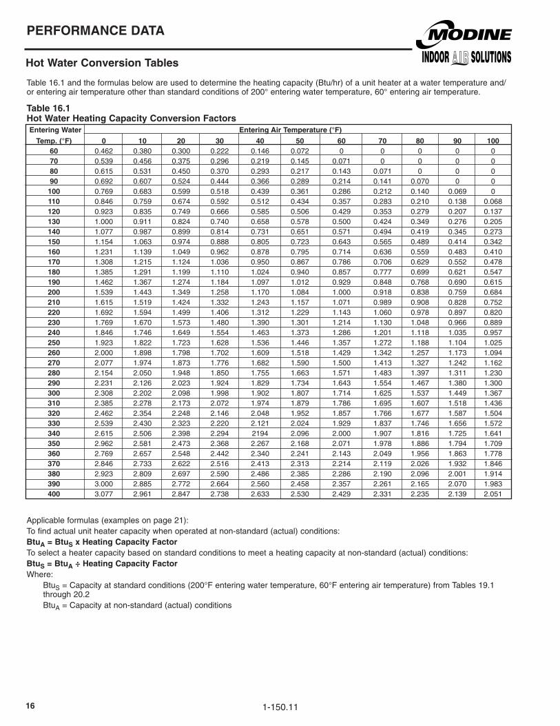
Table16.1andtheformulasbelowareusedtodeterminetheheatingcapacity(Btu/hr)ofaunitheateratawatertemperatureand/orenteringairtemperatureotherthanstandardconditionsof200°enteringwatertemperature,60°enteringairtemperature.
Table 1�.1Hot Water Heating Capacity Conversion factors Entering Water Entering air Temperature (°f)
Temp. (°f) 0 10 �0 30 40 50 �0 70 80 90 100 �0 0.462 0.380 0.300 0.222 0.146 0.072 0 0 0 0 0 70 0.539 0.456 0.375 0.296 0.219 0.145 0.071 0 0 0 0 80 0.615 0.531 0.450 0.370 0.293 0.217 0.143 0.071 0 0 0 90 0.692 0.607 0.524 0.444 0.366 0.289 0.214 0.141 0.070 0 0 100 0.769 0.683 0.599 0.518 0.439 0.361 0.286 0.212 0.140 0.069 0 110 0.846 0.759 0.674 0.592 0.512 0.434 0.357 0.283 0.210 0.138 0.068 1�0 0.923 0.835 0.749 0.666 0.585 0.506 0.429 0.353 0.279 0.207 0.137 130 1.000 0.911 0.824 0.740 0.658 0.578 0.500 0.424 0.349 0.276 0.205 140 1.077 0.987 0.899 0.814 0.731 0.651 0.571 0.494 0.419 0.345 0.273 150 1.154 1.063 0.974 0.888 0.805 0.723 0.643 0.565 0.489 0.414 0.342 1�0 1.231 1.139 1.049 0.962 0.878 0.795 0.714 0.636 0.559 0.483 0.410 170 1.308 1.215 1.124 1.036 0.950 0.867 0.786 0.706 0.629 0.552 0.478 180 1.385 1.291 1.199 1.110 1.024 0.940 0.857 0.777 0.699 0.621 0.547 190 1.462 1.367 1.274 1.184 1.097 1.012 0.929 0.848 0.768 0.690 0.615 �00 1.539 1.443 1.349 1.258 1.170 1.084 1.000 0.918 0.838 0.759 0.684 �10 1.615 1.519 1.424 1.332 1.243 1.157 1.071 0.989 0.908 0.828 0.752 ��0 1.692 1.594 1.499 1.406 1.312 1.229 1.143 1.060 0.978 0.897 0.820 �30 1.769 1.670 1.573 1.480 1.390 1.301 1.214 1.130 1.048 0.966 0.889 �40 1.846 1.746 1.649 1.554 1.463 1.373 1.286 1.201 1.118 1.035 0.957 �50 1.923 1.822 1.723 1.628 1.536 1.446 1.357 1.272 1.188 1.104 1.025 ��0 2.000 1.898 1.798 1.702 1.609 1.518 1.429 1.342 1.257 1.173 1.094 �70 2.077 1.974 1.873 1.776 1.682 1.590 1.500 1.413 1.327 1.242 1.162 �80 2.154 2.050 1.948 1.850 1.755 1.663 1.571 1.483 1.397 1.311 1.230 �90 2.231 2.126 2.023 1.924 1.829 1.734 1.643 1.554 1.467 1.380 1.300 300 2.308 2.202 2.098 1.998 1.902 1.807 1.714 1.625 1.537 1.449 1.367 310 2.385 2.278 2.173 2.072 1.974 1.879 1.786 1.695 1.607 1.518 1.436 3�0 2.462 2.354 2.248 2.146 2.048 1.952 1.857 1.766 1.677 1.587 1.504 330 2.539 2.430 2.323 2.220 2.121 2.024 1.929 1.837 1.746 1.656 1.572 340 2.615 2.506 2.398 2.294 2194 2.096 2.000 1.907 1.816 1.725 1.641 350 2.962 2.581 2.473 2.368 2.267 2.168 2.071 1.978 1.886 1.794 1.709 3�0 2.769 2.657 2.548 2.442 2.340 2.241 2.143 2.049 1.956 1.863 1.778 370 2.846 2.733 2.622 2.516 2.413 2.313 2.214 2.119 2.026 1.932 1.846 380 2.923 2.809 2.697 2.590 2.486 2.385 2.286 2.190 2.096 2.001 1.914 390 3.000 2.885 2.772 2.664 2.560 2.458 2.357 2.261 2.165 2.070 1.983 400 3.077 2.961 2.847 2.738 2.633 2.530 2.429 2.331 2.235 2.139 2.051
Applicableformulas(examplesonpage21):Tofindactualunitheatercapacitywhenoperatedatnon-standard(actual)conditions:Btua = BtuS x Heating Capacity factorToselectaheatercapacitybasedonstandardconditionstomeetaheatingcapacityatnon-standard(actual)conditions:BtuS = Btua ÷ Heating Capacity factorWhere:
BtuS=Capacityatstandardconditions(200°Fenteringwatertemperature,60°Fenteringairtemperature)fromTables19.1through20.2BtuA=Capacityatnon-standard(actual)conditions
PERfORMaNCE DaTa
Hot Water Conversion Tables
1-150.11

17
PERfORMaNCE DaTa
Hot Water Conversion Tables
Table 17.� - Ethylene Glycol Correction factors ➁Table17.2isusedtodeterminehowglycolsolutionsaffectheatercapacity.Thesefactorsshouldbeappliedtotheheatercapacityatactualenteringwaterandairtemperatureconditions.
➁ForPropyleneGlycolsolutioncorrectionfactor,multiplyEthyleneGlycolcorrectionfactorby0.95.
Applicableformulas(examplesonpage21):Tofindactualunitheatercapacitywhenoperatedwithglycolsolution:BtuaG = BtuS (or Btua) x Glycol Correction factor Toselectaheatercapacitybasedonstandardconditionstomeetaheatingcapacitywithaglycolsolution:BtuS (or Btua) = BtuaG ÷ Glycol Correction factorWhere:
BtuS =Capacityatstandardconditions(200°Fenteringwatertemperature,60°Fenteringairtemperature)fromTables19.1through20.2BtuA =Capacityatnon-standard(actual)conditionsBtuAG=Capacitywithglycolsolution
Table 17.3 - Hot Water Unit Heater Mounting Height Correction factors ➂ Table17.3isusedtodeterminehowhotwatertemperaturesotherthan200°Faffectmountingheight.
➂ Factorsareforusewithenteringairtemperaturesthatrangefrom50°to70°F
Applicableformula(examplesonpage21):Max. Mounting Heighta = Max. Mounting HeightS x Correction factorWhere: Max.MountingHeightA=Maximummountingheightatactualconditions Max.MountingHeightS=Maximummountingheightatstandardconditions
Ethylene Glycol Solution % Solution Temperature (°f) �0% 30% 40% 50% �0% 70% 80% �0 0.99 0.96 0.93 0.89 0.85 0.81 0.76 100 0.99 0.96 0.93 0.89 0.85 0.81 0.76 150 0.99 0.96 0.94 0.90 0.87 0.83 0.78 �00 0.99 0.96 0.94 0.92 0.88 0.85 0.81 �50 0.98 0.96 0.94 0.92 0.89 0.86 0.82 300 0.98 0.95 0.95 0.92 0.90 0.87 0.83 350 0.98 0.95 0.95 0.93 0.91 0.88 0.84 400 0.97 0.95 0.95 0.93 0.92 0.89 0.85
Table 17.1 - Minimum Water flow and Water Volume (gallons) ➀
18 0.25 5 0.13 279 4.5 60 0.97 42 0.5 10 0.15 24 0.25 5 0.13 333 4.5 100 1.24 59 0.75 15 0.23 33 0.40 10 0.41 385 4.5 100 1.24 78 1 20 0.31 47 0.40 10 0.41 500 6 100 1.66 95 1.25 25 0.38 63 0.50 20 0.66 610 6 100 1.98 139 1 30 0.43 86 0.50 20 0.66 952 14 200 6.50 139 1.25 40 0.54 108 0.50 30 0.98 193 1.5 50 0.65 121 0.50 30 0.98 212 2 60 0.86 165 2.00 30 1.35 279 2.25 75 0.97 193 2.00 50 1.45 333 2.25 75 1.24 258 2.50 70 2.20 385 2.25 75 1.24 290 2.50 70 2.20 500 3 100 1.66 340 2.50 70 2.50 610 6 100 1.98 952 14 200 6.50
Type ModelMin. GPM
Max.GPM
Coil Volume(gals)
Type
HORIZOnTAL
DELIVERY
HSB/HC
POWER-
THROWTM
PT/PTN
ModelMin. GPM
Max.GPM
Coil Volume(gals)
Type
VERTICAL
DELIVERY
V/VN
ModelMin. GPM
Max.GPM
Coil Volume(gals)
Entering Water Correction Entering Water Correction Entering Water Correction Temperature, °f factor Temperature, °f factor Temperature, °f factor 140 1.33 �30 0.91 3�0 0.74 150 1.25 �40 0.89 330 0.72 1�0 1.19 �50 0.86 340 0.71 170 1.13 ��0 0.84 350 0.70 180 1.08 �70 0.82 3�0 0.69 190 1.04 �80 0.80 370 0.67 �00 1.00 �90 0.78 380 0.66 �10 0.97 300 0.77 390 0.65 ��0 0.94 310 0.75 400 0.64
➀ Waterflowandwatervolumeisthesameforstandardcoilsandlow-outlettemperaturecoils
1-150.11

1-150.1118
Table18.1isusedtodeterminehowwatertemperaturedropaffectsheatercapacityinBtu,waterflowrateinGPMandpressuredropinfeetofwater.Thesefactorsshouldbeappliedtothevaluesatactualenteringwaterandairtemperatureconditions.
Table 18.1Correction factors for Varying Water Temperature Drop ➀ Water Temperature Drop, °f 5 10 15 �0 �5 30 35 40 45 50 55 �0 Btu Correction factor 1.23 1.13 1.06 1.00 0.95 0.90 0.86 0.82 0.78 0.72 0.69 0.67 GPM Correction factor 4.64 2.21 1.40 1.00 0.76 0.61 0.50 0.42 0.36 0.30 0.26 0.23 WPD Correction factor 17.24 4.32 1.85 1.00 0.61 0.41 0.30 0.22 0.18 0.14 0.12 0.11
➀Watertemperaturedropcorrectionfactorsvalidonlyforstandard200°Fenteringwaterand60°Fairtemperatureconditions.
Applicableformulas(examplesonpage21):
Tofindactualunitheatercapacityorflowrateorwaterpressuredropwhenoperatedatnon-standard(actual)conditions:
Btua = BtuS x Btu Correction factor
GPMa = GPMS x GPM Correction factor
WPDa = WPDS x WPD Correction factor
Toselectaheatercapacitybasedonstandardconditionstomeetaheatingcapacityatnon-standard(actual)conditions:
BtuS = Btua ÷ Btu Correction factor
Where:BtuS =Capacityatstandardconditions(200°Fenteringwatertemperature,60°Fenteringairtemperature)fromTables19.1
through20.2BtuA =Capacityatnon-standard(actual)conditionsGPMS =Flowrateatstandardconditions(200°Fenteringwatertemperature,60°Fenteringairtemperature)fromTables19.1
through20.2GPMA =Flowrateatnon-standard(actual)conditionsWPDS =Waterpressuredropatstandardconditions(200°Fenteringwatertemperature,60°Fenteringairtemperature)from
Tables19.1through20.2WPDA =Waterpressuredropatnon-standard(actual)conditions
Othermiscellaneoususefulformulas:
faTa = EaTa + [(4�0 + EaTa) x (Btua) ÷ (573 x Cfms)] for HSB and HC units only
faTa = EaTa + [(4�0 + EaTa) ÷ ((573 x Cfms ÷ Btua) - 1)] for V/VN and PT/PTN units only
WTDa = Btua ÷ (480 x GPMa)
Where:EATA =EnteringairtemperatureatactualconditionsFATA =FinalairtemperatureatactualconditionsBtuA =CapacityatactualconditionsCfmS =UnitairflowasfoundinTables19.1through20.2GPMA =WaterflowrateatactualconditionsinGPMWTDA =Watertemperaturedropatactualconditions
PERfORMaNCE DaTa
Hot Water Conversion Tables - Miscellaneous formulas

1-150.11 19
Table 19.1Performance Data for Standard Units at Standard Conditions of �00°f Entering Water and �0°f Entering air High Motor Speed
Water Data air Data Motor Data Pressure Maximum Heat Throw Drop Sound Mounting or Spread Outlet final air Model (ft. of Min/Max Class Height @ Max. Velocity Temp. approx.
Type No. Btu/hr. GPM Water) GPM ➃ (ft.) ➀ Height ➀ Cfm ➁ (fpm) (°f) Hp RPM
HSB/HC-18 12,600 1.3 0.5 0.25/5.0 II 9 18 340 615 93 1/60 1550 HSB/HC-24 16,200 1.7 0.8 0.25/5.0 II 10 19 370 675 100 1/25 1550 HSB/HC-33 21,700 2.3 0.2 0.4/10.0 II 11 22 630 675 91 1/25 1550 HSB/HC-47 30,900 3.2 0.4 0.4/10.0 III 13 30 730 785 98 1/12 1550 HSB/HC-63 45,600 4.7 0.6 0.5/20.0 III 15 31 1120 680 97 1/12 1550Horizontal HSB/HC-86 60,200 6.3 1.0 0.5/20.0 III 16 33 1340 820 101 1/8 1625 Delivery HSB/HC-108 83,700 8.7 2.8 0.5/30.0 III 18 33 2010 775 98 1/8 1625 HSB/HC-121 93,000 9.7 3.3 0.7/30.0 III 17 27 1775 700 107 1/5 1075 HSB/HC-165 130,900 13.6 8.6 2.0/30.0 IV 20 43 3240 870 96 1/3 1075 HSB/HC-193 143,000 14.9 1.4 2.0/50.0 IV 19 40 2900 790 105 1/3 1075 HSB/HC-258 201,900 21.0 5.7 2.5/70.0 V 20 47 4560 740 100 1/2 1075 HSB/HC-290 228,600 23.8 7.1 2.5/70.0 V 21 49 4590 750 105 1/2 1075 HSB/HC-340 271,100 28.2 11.3 2.5/70.0 V 21 49 5130 720 108 1/2 1075 PT/PTn-279 192,300 20.0 0.2 4.5/60.0 V 17 106 5460 2165 94 1/2 1075 PT/PTn-333 238,500 24.8 0.4 4.5/100.0 VI 18 117 5980 2165 99 3/4 1140 Power- PT/PTn-385 276,100 28.8 0.6 4.5/100.0 VI 18 122 7680 1860 95 1 1140 Throw™ PT/PTn-500 358,000 37.3 0.5 6.0/100.0 VI 19 138 10,390 2520 93 1-1/2 1140 ➂ PT/PTn-610 450,400 46.9 1.0 6.0/100.0 VI 21 149 11,750 2315 97 1-1/2 1140 PT-952 721,600 75.2 1.1 14.0/200.0 VI 22 154 12,166 2321 120 2 1140 V/Vn-42 30,100 3.1 0.6 0.5/10.0 II 12 1� 18 1� 950 825 90 1/30 1050 V/Vn-59 42,600 4.4 0.5 0.75/15.0 II 15 �0 22 15 1155 1005 96 1/30 1050 V/Vn-78 57,000 5.9 0.5 1.0/20.0 II 16 �� 24 1� 1590 1065 95 1/15 1050 V/Vn-95 69,300 7.2 0.5 1.25/25.0 II 16 �� 24 1� 1665 1120 101 1/15 1050 V/Vn-139 106,600 11.1 2.6 1.0/30.0 III 19 �� 29 19 2660 1285 99 1/5 1075 Vertical V/Vn-161 123,200 12.8 2.2 1.25/40.0 IV 21 �9 32 �� 2945 1420 101 1/3 1075Delivery V/Vn-193 147,200 15.3 2.2 1.5/50.0 IV 23 3� 35 �4 3500 1690 101 1/3 1075 ➂ V/Vn-212 161,700 16.8 1.5 2.0/60.0 IV 23 3� 35 �4 3610 1740 104 1/3 1075 V/Vn-247 188,700 19.7 2.1 2.0/60.0 V 28 37 41 �8 4820 1910 98 1/2 1075 V/Vn-279 212,600 22.2 2.1 2.25/75.0 V 32 40 48 3� 5460 2165 98 1/2 1075 V/Vn-333 260,100 27.1 3.8 2.25/75.0 V 32 40 48 3� 5980 2165 102 3/4 1140 V/Vn-385 302,100 31.5 5.0 2.25/75.0 VI 32 39 48 3� 7680 1860 98 1 1140 V/Vn-500 391,700 40.8 4.8 3.0/100.0 VI 39 47 60 40 10,390 2520 96 1-1/2 1140 V/Vn-610 450,400 46.9 1.0 6.0/100.0 VI 38 4� 57 39 11,750 2315 97 1-1/2 1140 V-952 721,600 75.2 1.1 14.0/200.0 VI 39 �3 60 70 12,166 2321 120 2 1140
Table 19.�Performance Data for Standard Units at Standard Conditions of �00°f Entering Water and �0°f Entering airReduced Motor Speeds ➄ Water Data air Data Motor Data Pressure Maximum Drop Sound Mounting Heat Throw Outlet final air Model (ft. of Class Height @ Max. Velocity Temp. approx. Type No. Btu/hr. GPM Water) ➃ (ft.) ➀ Height ➀ Cfm ➁ (fpm) (°f) Hp RPM
HSB/HC-18 9900 1.3 0.5 I 9 11 220 400 101 1/60 1000 HSB/HC-24 12,400 1.7 0.8 I 10 12 230 425 109 1/25 1000Horizontal HSB/HC-33 16,700 2.3 0.2 I 11 14 395 430 98 1/25 1000Delivery HSB/HC-47 23,600 3.2 0.4 II 13 18 450 490 107 1/12 1000 HSB/HC-63 34,600 4.7 0.6 II 15 18 685 420 106 1/12 1000 HSB/HC-86 45,900 6.3 1.0 II 16 20 825 515 110 1/8 1000 HSB/HC-108 64,300 8.7 2.8 II 18 20 1255 490 106 1/8 1000
➀Horizontalunitswithhorizontallouversopen30°fromverticalplane.Verticaltypesequippedwithconejetdeflector,bladesfullyopenedareshowninbold.non-boldedmountingheight/spreaddataisforunitswithoutdeflectors.Pleaseseepage22foradditionaloutletaccessoryperformancedata.
➁CfmforhorizontaltypesisenteringCfm.CfmforverticalandPower-Throw™typesisleavingCfm.➂VandPTmodelshavecoppertubes,VnandPTnmodelshave90/10cupro-nickeltubes.➃Seepage8forSoundClassdefinitions.➄RequiresSolidStateMotorSpeedController.
PERfORMaNCE DaTa
Hot Water Performance Data - Standard Models

1-150.11�0
Table �0.1Performance Data for Low Outlet Temperature Units at Standard Conditions of �00°f Entering Water and �0°f Entering air – High Motor Speed
Water Data air Data Motor Data
Pressure Maximum Heat Throw
Drop Sound Mounting or Spread Outlet final air
Model (ft. of Min/Max Class Height @ Max. Velocity Temp. approx.
Type No. Btu/hr. GPM Water) GPM ➃ (ft.) ➀ Height ➀ Cfm ➁ (fpm) (°f) Hp RPM
HSB/HC-18L 11,300 1.2 0.4 0.25/5.0 II 10 21 364 650 88 1/60 1550
HSB/HC-24L 13,700 1.4 0.6 0.25/5.0 II 12 22 435 775 88 1/25 1550
HSB/HC-33L 19,300 2.0 0.2 0.4/10.0 II 13 26 695 730 85 1/25 1550
HSB/HC-47L 21,100 2.2 0.2 0.4/10.0 III 15 34 855 890 82 1/12 1550
HSB/HC-63L 37,900 4.0 0.4 0.5/20.0 III 17 35 1170 695 89 1/12 1550
Horizontal HSB/HC-86L 44,600 4.6 0.6 0.5/20.0 III 18 38 1510 890 87 1/8 1625
Delivery HSB/HC-108L 66,100 6.9 1.8 0.8/30.0 III 20 38 2150 815 88 1/8 1625
HSB/HC-121L 66,700 6.9 1.9 0.8/30.0 III 19 31 2070 785 89 1/5 1075
HSB/HC-165L 113,200 11.8 6.6 2.0/30.0 IV 22 48 3480 920 89 1/3 1075
HSB/HC-258L 147,400 15.4 3.2 2.5/70.0 V 23 54 4655 735 89 1/2 1075
HSB/HC-290L 161,100 16.8 3.7 2.5/70.0 V 24 56 5040 800 89 1/2 1075
HSB/HC-340L 200,900 20.9 6.6 2.5/70.0 V 24 56 5575 760 93 1/2 1075
Power- PT/PTn-Throw™➂ 610L V/Vn-42L 23,000 2.4 0.4 0.5/10.0 II 14 18 21 14 960 835 83 1/30 1050 V/Vn-59L 32,600 3.4 0.3 0.75/15.0 II 17 �3 26 17 1190 1035 86 1/30 1050 V/Vn-78L 43,600 4.5 0.3 1.0/20.0 II 20 �8 31 �1 1740 1170 84 1/15 1050 V/Vn-95L 53,100 5.5 0.3 1.25/25.0 II 20 �8 31 �1 1760 1180 89 1/15 1050 V/Vn-139L 81,200 8.5 1.6 1.0/30.0 III 24 33 37 �5 2860 1380 87 1/5 1075 V/Vn-161L 93,900 9.8 1.3 1.25/40.0 IV 28 37 41 �8 3400 1640 86 1/3 1075 Vertical V/Vn-193L 112,500 11.7 1.3 1.5/50.0 IV 29 38 44 �9 3710 1790 89 1/3 1075Delivery V/Vn-212L 123,400 12.9 0.9 2.0/60.0 IV 29 38 44 �9 3,830 1845 91 1/3 1075 ➂ V/Vn-247L 143,600 15.0 1.2 2.0/60.0 V 34 45 51 35 5110 2030 87 1/2 1075 V/Vn-279L 162,200 16.9 1.2 2.25/75.0 V 38 48 57 39 5790 2300 87 1/2 1075 V/Vn-333L 198,300 20.7 2.3 2.25/75.0 V 38 48 57 39 6340 2300 90 3/4 1140 V/Vn-385L 229,100 23.9 3.0 2.25/75.0 VI 38 4� 57 49 8140 1970 87 1 1140 V/Vn-500L 295,000 30.7 2.8 3.0/100.0 VI 48 57 72 49 11,000 2670 85 1-1/2 1140 V/Vn-610L 344,900 35.9 0.6 6.0/100.0 VI 47 55 70 48 12,400 2445 86 1-1/2 1140 V-952L 546,700 56.9 0.7 14.0/100.0 VI 48 �1 72 �8 12,800 2440 102 2 1140
Table �0.�Performance Data for Low Outlet Temperature Units at Standard Conditions of �00°f Entering Water and �0°f Entering air – Reduced Motor Speeds ➄ Water Data air Data Motor Data
Pressure Maximum
Drop Sound Mounting Heat Throw Outlet final air
Model (ft. of Class Height @ Max. Velocity Temp. approx.
Type No. Btu/hr. GPM Water) ➃ (ft.) ➀ Height ➀ Cfm ➁ (fpm) (°f) Hp RPM
HSB/HC-18L 8700 1.2 0.4 I 10 13 230 410 94 1/60 1000
HSB/HC-24L 10,400 1.4 0.6 I 12 14 265 475 95 1/25 1000
Horizontal HSB/HC-33L 14,700 2.0 0.2 I 13 15 430 455 91 1/25 1000
Delivery HSB/HC-47L 16,300 2.2 0.2 II 15 20 540 570 87 1/12 1000
HSB/HC-63L 29,000 4.0 0.4 II 17 21 725 435 96 1/12 1000
HSB/HC-86L 33,900 4.6 0.6 II 18 23 925 550 93 1/8 1000
HSB/HC-108L 50,500 6.9 1.8 II 20 23 1330 510 94 1/8 1000
➀Horizontalunitswithhorizontallouversopen30°fromverticalplane.Verticaltypesequippedwithconejetdeflector,bladesfullyopenedareshowninbold.non-boldedmountingheight/spreaddataisforunitswithoutdeflectors.Pleaseseepage22foradditionaloutletaccessoryperformancedata.
➁CfmforhorizontaltypesisenteringCfm.CfmforverticalandPower-Throw™typesisleavingCfm.➂VandPTmodelshavecoppertubes,VnandPTnmodelshave90/10cupro-nickeltubes.➃Seepage8forSoundClassdefinitions.➄RequiresSolidStateMotorSpeedController.
PERfORMaNCE DaTa
Hot Water Performance Data - Low Outlet Temperature Models
344,900 35.9 0.6 6.0/100.0 VI 23 164 12,400 2445 86 1-1/2 1140

1-150.11 �1
PERfORMaNCE DaTa
Hot Water Conversion Tables - Example Calculations
Conversion factor example #1:
Whatisthecapacity(Btu/hr),waterflowrate(GPM),watertemperaturedrop(°F)andfinalairtemperature(°F)foranHSB86at240°Fenteringwatertemperature(EWT)and70°Fenteringairtemperature(EAT)?Whatisthemaximummountingheight?
Solution:
Thefactors/datanecessarytosolvethisproblemareasfollows:• Hotwaterheatingcapacityconversionfactorfor240°FEWTand70°Fenteringairis1.201,fromTable16.1.• ThestandardratedcapacityofanHSB86is60,200Btu/hr,fromTable19.1.•ThestandardratedcapacityofanHSB86isbasedonwaterflowrateof6.3GPM,fromTable19.1.•ThestandardhighmotorspeedairflowofanHSB86is1340CFM,fromTable19.1.•Themaximummountingheight,atstandardconditionsforanHSB86is16feet,fromTable19.1.•Themountingheightcorrectionfactorfor240°FEWTis0.89fromTable17.2.
BtuA=BtuSxHeatingCapacityFactor=60,200x1.201=72,300Btu/hr
Forwaterflowrate,sinceonlytheenteringwaterandairtemperatureconditionshavechanged,thewaterflowratewillremain6.3GPM.
WTDA=BtuA÷(480xGA)=72,300Btu/hr÷(480x6.3GPM)=23.9°F
FATA=EATA+[(460+EATA)x(BtuA)÷(576xCfms)]=70°F+[(460+70°F)x(72,300)÷(576x1340)]=120°F
Max.MountingHeightA=Max.MountingHeightSxCorrectionFactor=16ft.x0.89=14.2feet
Conversion factor example #�:
Selectaverticalunitheatermodelthatcandeliveratleast150,000Btu/hrwith160°FEWTand60°FEAT.Whatwillbetherequiredwaterflowrate,watertemperaturedrop,finalairtemperatureandmaximummountingheight?
Solution:
Thefactors/datanecessarytosolvethisproblemareasfollows:•Hotwaterheatingcapacityconversionfactorfor160°FEWTand60°Fenteringairis0.714,fromTable16.1.•Themountingheightcorrectionfactorfor160°FEWTis1.19,fromTable17.2.
BtuS=BtuA÷HeatingCapacityFactor=150,000÷0.714=210,084Btu/hr(atstandardconditions)FromTable19.1,aV-279modelwillmeettherequirementwitharatedcapacityof212,600Btu/hratstandardconditions.
ThecapacityoftheV-279atactualconditionswillbeBtuA=BtuSxHeatingCapacityFactor=212,600x0.714=151,796Btu/hr.
Sincethecapacitywascalculatedbasedoffstandardconditionswithfactorsforchangesinenteringwaterandairtemperatureconditions,thewaterflowratewillremain22.2GPM.
WTDA=BtuA÷(480xGPMA)=151,796Btu/hr÷(480x22.2GPM)=14.2°F
FATA=EATA+[(460+EATA)÷((576xCfms÷BtuA)-1)]=60°F+[(460+60°F)÷((576x5,460÷151,796)-1)]=86.4°F
Max.MountingHeightA=Max.MountingHeightSxCorrectionFactor=40ft.(withcone-jetdeflector)x1.19=47.6feet

1-150.11��
PERfORMaNCE DaTa
Maximum Mounting Heights for Vertical Outlet accessories, Dimensions
Cone-Jet Truncone One Way Louvers Two Way Louvers
Standard L.O.T. Standard L.O.T. Standard L.O.T. Standard L.O.T.
Model H S H S H S H S H S H S H S H S
V/VN-4� 15 11 17 13 8 19 9 23 13 11 15 13 8 22 9 26 V/VN-59 19 14 22 16 9 25 11 28 16 14 18 16 10 28 11 32 V/VN-78 20 15 26 19 11 26 14 33 17 15 22 19 11 30 13 38 V/VN-95 20 15 26 19 11 26 14 33 17 15 22 19 11 30 13 38V/VN-139 24 18 31 23 13 32 17 40 21 18 26 23 13 36 16 46 V/VN-1�1 27 20 35 26 14 35 18 46 23 20 30 26 14 40 18 52V/VN-193 30 22 36 27 16 39 19 47 25 22 31 27 15 44 19 54V/VN-�1� 30 22 36 27 16 39 19 47 15 44 19 54 25 22 31 27V/VN-�47 34 26 42 32 17 46 21 56 18 52 22 64 30 26 37 32V/VN-�79 37 30 45 36 18 53 22 63 21 60 25 72 35 30 41 36V/VN-333 37 30 45 36 17 53 20 63 21 60 25 72 35 30 41 3V/VN-385 36 30 43 36 17 53 20 63 21 60 25 72 35 30 41 36V/VN-500 44 37 54 45 19 65 24 79 26 74 31 90 42 37 51 45V/VN-�10 43 36 52 44 19 63 24 77 25 72 30 88 41 41 50 44 V-95� - - - - - - - - 26 66 31 82 45 56 54 65
Table ��.1Mounting Height/Spread for Vertical Unit air Outlet accessories ➀➁➂➃
➀Datashownforstandard2lb.steam,60°Fenteringairtemperatureconditions.Forlouversorcone-jet,datashownfordeflectorsinfully-openedposition.Formountingheight/spreadatsteampressuresotherthan2lb.,multiplythevaluebythecorrectionfactorinTable11.1.
➁Formountingheightandspreadforhotwater,multiplethevaluesaboveby1.06toapproximatethemountingheightandspreadat200°Fenteringwatertemperature.Forenteringwatertemperatureotherthan200°F,multiplythevaluesaboveby1.06andthanmultiplythecorrectionfactorinTable16.2
➂Alldimensionsinfeet.➃VmodelshavecoppertubesandVnmodelshave90/10cupro-nickeltubes.
HHHH H
S SS S S
COnEJET TRUnCOnE OnEWAYLOUVERS TWOWAYLOUVERS
Table ��.� - Vertical air Outlet accessories Dimensions ➄ Model Cone-Jet Truncone Louvers Number L T M X P Z V-4�, V-59 6-1/2 18-7/8 12 22 6-1/2 16-7/8 V-78, V-95 6-1/2 18-7/8 12 22 6-1/2 16-7/8 V-139, V-�1� 7-1/2 24-3/4 13 27 7-1/2 19-3/4 V-�47, V-�79 8 26-7/8 16 34 8 22-3/4 V-333 8-1/2 28 16 34 8-1/2 22-3/4 V-385, V-500 10 22-3/4 21 41 10 27-3/4 V-�10 10-1/2 36-3/4 21 41 10-1/2 30-3/4 V-95� - - - - 19-1/2 32
figure ��.� - Vertical air Outlet accessories
➄Alldimensionsininches.
L
T
XZ
PM
CONE-JET TRUNCONE LOUVER
1-150.11 �3
PERfORMaNCE DaTa
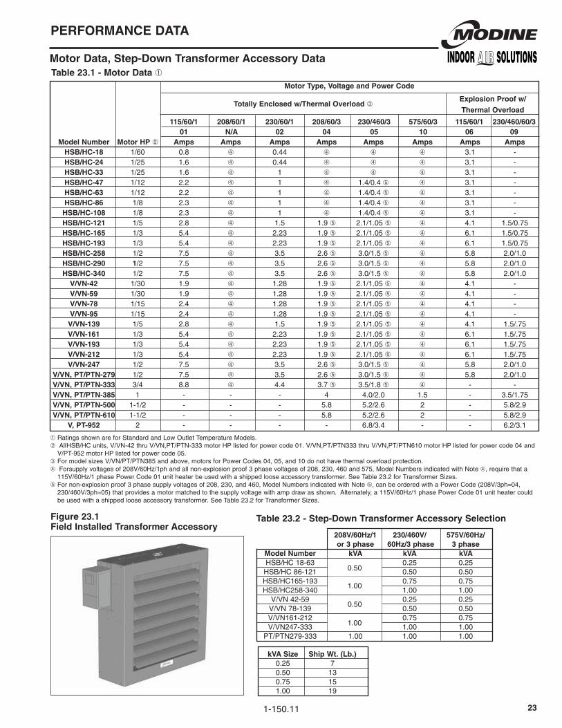
Motor Data, Step-Down Transformer accessory Data
➀RatingsshownareforStandardandLowOutletTemperatureModels.➁ AllHSB/HCunits,V/Vn-42thruV/Vn,PT/PTn-333motorHPlistedforpowercode01.V/Vn,PT/PTn333thruV/Vn,PT/PTn610motorHPlistedforpowercode04and
V/PT-952motorHPlistedforpowercode05.➂FormodelsizesV/Vn/PT/PTn385andabove,motorsforPowerCodes04,05,and10donothavethermaloverloadprotection.➃Forsupplyvoltagesof208V/60Hz/1phandallnon-explosionproof3phasevoltagesof208,230,460and575,Modelnumbersindicatedwithnote➃,requirethata
115V/60Hz/1phasePowerCode01unitheaterbeusedwithashippedlooseaccessorytransformer.SeeTable23.2forTransformerSizes.➄Fornon-explosionproof3phasesupplyvoltagesof208,230,and460,Modelnumbersindicatedwithnote➄,canbeorderedwithaPowerCode(208V/3ph=04,
230/460V/3ph=05)thatprovidesamotormatchedtothesupplyvoltagewithampdrawasshown.Alternately,a115V/60Hz/1phasePowerCode01unitheatercouldbeusedwithashippedlooseaccessorytransformer.SeeTable23.2forTransformerSizes.
Table �3.1 - Motor Data ➀ Motor Type, Voltage and Power Code
115/�0/1 �08/�0/1 �30/�0/1 �08/�0/3 �30/4�0/3 575/�0/3 115/�0/1 �30/4�0/�0/3 01 N/a 0� 04 05 10 0� 09 Model Number Motor HP ➁ amps amps amps amps amps amps amps amps HSB/HC-18 1/60 0.8 ➃ 0.44 ➃ ➃ ➃ 3.1 - HSB/HC-�4 1/25 1.6 ➃ 0.44 ➃ ➃ ➃ 3.1 - HSB/HC-33 1/25 1.6 ➃ 1 ➃ ➃ ➃ 3.1 - HSB/HC-47 1/12 2.2 ➃ 1 ➃ 1.4/0.4➄ ➃ 3.1 - HSB/HC-�3 1/12 2.2 ➃ 1 ➃ 1.4/0.4➄ ➃ 3.1 - HSB/HC-8� 1/8 2.3 ➃ 1 ➃ 1.4/0.4➄ ➃ 3.1 - HSB/HC-108 1/8 2.3 ➃ 1 ➃ 1.4/0.4➄ ➃ 3.1 - HSB/HC-1�1 1/5 2.8 ➃ 1.5 1.9➄ 2.1/1.05➄ ➃ 4.1 1.5/0.75 HSB/HC-1�5 1/3 5.4 ➃ 2.23 1.9➄ 2.1/1.05➄ ➃ 6.1 1.5/0.75 HSB/HC-193 1/3 5.4 ➃ 2.23 1.9➄ 2.1/1.05➄ ➃ 6.1 1.5/0.75 HSB/HC-�58 1/2 7.5 ➃ 3.5 2.6➄ 3.0/1.5➄ ➃ 5.8 2.0/1.0 HSB/HC-�90 1/2 7.5 ➃ 3.5 2.6➄ 3.0/1.5➄ ➃ 5.8 2.0/1.0 HSB/HC-340 1/2 7.5 ➃ 3.5 2.6➄ 3.0/1.5➄ ➃ 5.8 2.0/1.0 V/VN-4� 1/30 1.9 ➃ 1.28 1.9➄ 2.1/1.05➄ ➃ 4.1 - V/VN-59 1/30 1.9 ➃ 1.28 1.9➄ 2.1/1.05➄ ➃ 4.1 - V/VN-78 1/15 2.4 ➃ 1.28 1.9➄ 2.1/1.05➄ ➃ 4.1 - V/VN-95 1/15 2.4 ➃ 1.28 1.9➄ 2.1/1.05➄ ➃ 4.1 - V/VN-139 1/5 2.8 ➃ 1.5 1.9➄ 2.1/1.05➄ ➃ 4.1 1.5/.75 V/VN-1�1 1/3 5.4 ➃ 2.23 1.9➄ 2.1/1.05➄ ➃ 6.1 1.5/.75 V/VN-193 1/3 5.4 ➃ 2.23 1.9➄ 2.1/1.05➄ ➃ 6.1 1.5/.75 V/VN-�1� 1/3 5.4 ➃ 2.23 1.9➄ 2.1/1.05➄ ➃ 6.1 1.5/.75 V/VN-�47 1/2 7.5 ➃ 3.5 2.6➄ 3.0/1.5➄ ➃ 5.8 2.0/1.0 V/VN, PT/PTN-�79 1/2 7.5 ➃ 3.5 2.6➄ 3.0/1.5➄ ➃ 5.8 2.0/1.0 V/VN, PT/PTN-333 3/4 8.8 ➃ 4.4 3.7➄ 3.5/1.8➄ ➃ - - V/VN, PT/PTN-385 1 - - - 4 4.0/2.0 1.5 - 3.5/1.75 V/VN, PT/PTN-500 1-1/2 - - - 5.8 5.2/2.6 2 - 5.8/2.9 V/VN, PT/PTN-�10 1-1/2 - - - 5.8 5.2/2.6 2 - 5.8/2.9 V, PT-95� 2 - - - - 6.8/3.4 - - 6.2/3.1
Totally Enclosed w/Thermal Overload ➂Explosion Proof w/
Thermal Overload
figure �3.1 field Installed Transformer accessory
Table �3.� - Step-Down Transformer accessory Selection
�08V/�0Hz/1 �30/4�0V/ 575V/�0Hz/ or 3 phase �0Hz/3 phase 3 phase Model Number kVa kVa kVa HSB/HC18-63 0.25 0.25 HSB/HC86-121 0.50 0.50 HSB/HC165-193 1.00 0.75 0.75 HSB/HC258-340 1.00 1.00 V/Vn42-59 0.50 0.25 0.25 V/Vn78-139 0.50 0.50 V/Vn161-212 1.00 0.75 0.75 V/Vn247-333 1.00 1.00 PT/PTn279-333 1.00 1.00 1.00
kVa Size Ship Wt. (Lb.) 0.25 7 0.50 13 0.75 15 1.00 19
0.50
1.00
0.50
1.00

1-150.11�4
DIMENSIONaL DaTa
Dimensions - Horizontal air Delivery Models
D female approx. Model 115 Std. 115V Exp. Connections fan Shipping Number a B C Motor Motor E f G H NPT Diameter Wt. lb. HSB-18 12-3/8 13 6 5 12-1/4 - 3 - - 3/4 9 16 HSB-�4 12-3/8 13 6 5 12-1/4 - 3 - - 3/4 9 20 HSB-33 16-3/8 17-1/2 8-3/4 6 11-3/4 11 3-5/8 6 - 1-1/4 12 34 HSB-47 16-3/8 17-1/2 8-3/4 6 11-3/4 11 3-5/8 6 - 1-1/4 12 36 HSB-�3 20-7/16 21-1/2 8-3/4 7-3/4 12 15 3-5/8 6 - 1-1/4 14 48 HSB-8� 20-7/16 21-1/2 8-3/4 7-3/4 12 15 3-5/8 6 - 1-1/4 14 52 HSB-108 24-7/16 25-1/2 9-1/2 6-3/4 13-1/4 18 3-3/4 6-3/8 - 1-1/4 18 74 HSB-1�1 24-7/16 25-1/2 9-1/2 6-3/4 13-1/4 18 3-3/4 6-3/8 - 1-1/4 18 76 HSB-1�5 30-1/2 30-1/2 9-1/4 8-1/2 14 21-1/4 3-3/4 6-3/8 - 1-1/4 22 92 HSB-193 30-1/2 30-1/2 9-1/4 8-1/2 14 21-1/4 3-3/4 6-3/8 - 1-1/4 22 98 HSB-�58 38-1/2 38-1/2 12-1/2 10 15 18-1/2 3-5/8 7-7/8 - 1-1/4 22 162 HSB-�90 38-1/2 38-1/2 12-1/2 10 15 18-1/2 3-5/8 7-7/8 - 1-1/4 24 168 HSB-340 38-1/2 44-1/2 12-1/2 10 15 18-1/2 3-5/8 7-7/8 - 1-1/4 24 176 HC-18 11-1/2 13 6 5 12-1/4 5-5/8 2-1/4 4-1/8 7-1/2 1/2 9 16 HC-�4 11-1/2 13 6 5 12-1/4 5-5/8 2-1/4 4-1/8 7-1/2 1/2 9 20 HC-33 15 17-1/2 8-3/4 6 11-3/4 11 3-5/8 6 10 3/4 12 34 HC-47 15 17-1/2 8-3/4 6 11-3/4 11 3-5/8 6 10 3/4 12 35 HC-�3 18-1/2 21-1/2 8-3/4 7-3/4 12 15 3-5/8 6 14 3/4 12 48 HC-8� 18-1/2 21-1/2 8-3/4 7-3/4 12 15 3-5/8 6 14 3/4 14 52 HC-108 22-1/2 25-1/2 9-1/2 6-3/4 13-1/4 18 3-5/8 6-3/8 18 3/4 18 74 HC-1�1 22-1/2 25-1/2 9-1/2 6-3/4 13-1/4 18 3-5/8 6-3/8 18 3/4 18 76 HC-1�5 26-1/2 29-1/2 9-1/4 8-1/2 14 21-1/4 3-5/8 6-3/8 22 3/4 22 92 HC-193 30-1/2 32-1/2 9-1/4 8-1/2 14 21-1/4 3-5/8 4-3/4 26 1-1/4 22 98 HC-�58 38-1/2 38-1/2 12-1/2 10 15 18-1/2 3-5/8 8 34 1-1/4 22 163 HC-�90 38-1/2 38-1/2 12-1/2 10 15 18-1/2 3-5/8 8 34 1-1/4 24 168 HC-340 38-1/2 44-1/2 12-1/2 10 15 18-1/2 3-5/8 8 34 1-1/4 24 176
➁ Alldimensionsininches.➂ DimensionsshownareforStandardandLowOutletTemperatureModels.
figure �4.1 - Model Dimensions HSB18-193
figure �4.3 - Model Dimensions HC18-1�5
Table �4.1 - Model HS and HC Dimensions ➁➂
MOUNTING HOLESSIZES 33-86, 3/8"-16 TAP
SIZES 108-193, 1/2"-13 TAP
A
C5"
MIND
B
E F (PIPE CONNECTIONS)
G (MOUNTING HOLES)
MOUNTING HOLESSIZES 33-86, 3/8"-16 TAP
SIZES 108-165, 1/2"-13 TAP
A
C5"
MIND
B
E
G (MOUNTING HOLES)H (PIPE CONNECTION)
figure �4.� - Model Dimensions HSB�58-340
figure �4.4 - Model Dimensions HC193-340 ➀
FG
H
5"Min.
DC
BE
A Wall
PipeConnections
Mounting HolesMounting Holes1/2" - 13 Tap
FG
5"Min.
DC
BE
AWall
Mounting Holes1/2" - 13 Tap
Mounting Holes
PipeConnections
➀ VerticaldeflectorbladesshownarestandardonmodelsHC258-340andoptionalonmodelHC193.

1-150.11 �5
DIMENSIONaL DaTa
Dimensions - Vertical air Delivery Models
figure �5.1 - Model V/VN and PT/PTN Dimensions
Table �5.1 - Model V/VN and PT/PTN Dimensions ➀➁➂
Male Connections approx. Model fan NPT Shipping Number a B C D E f G Diameter Top Bottom Wt. (lb.) V/VN-4� 24-3/4 3-5/8 11-3/8 2-1/8 4-3/8 14-1/2 - 14 1-1/4 1-1/4 36 V/VN-59 24-3/4 5-1/8 11-3/8 2-1/8 4-3/8 14-1/2 - 14 1-1/4 1-1/4 42 V/VN-78 24-3/4 6-5/8 11-3/8 2-1/8 2-5/8 16-1/2 - 16 1-1/4 1-1/4 46 V/VN-95 24-3/4 8-1/8 11-3/8 2-1/8 2-5/8 16-1/2 - 16 1-1/4 1-1/4 48 V/VN-139 34-3/4 6-7/8 18-3/8 2-1/8 3 19-1/2 - 19 1-1/2 1 70 V/VN-1�1 34-3/4 8-3/8 18-3/8 2-1/8 3 19-1/2 - 19 1-1/2 1 80 V/VN-193 34-3/4 9-7/8 18-3/8 2-1/8 3 19-1/2 - 19 1-1/2 1 86 V/VN-�1� 34-3/4 12-7/8 18-3/8 2-1/2 3 19-1/2 - 19 2 1-1/4 94 V/VN-�47 34-3/4 12-7/8 18-3/8 2-1/2 3 21-1/2 - 21 2 1-1/4 108 V/VN-�79 34-3/4 14-3/8 18-3/8 2-1/2 3 21-1/2 - 21 2 1-1/4 112 V/VN-333 43-1/4 14-5/8 31-1/2 2-7/8 3-1/8 22-1/2 18-1/5 22 2-1/2 1-1/2 166 V/VN-385 43-1/4 14-1/2 31-1/2 2-7/8 3-1/2 27-1/2 18-1/5 27 2-1/2 1-1/2 168 V/VN-500 43-1/4 19 31-1/2 2-7/8 3-1/2 27-1/2 18-1/5 27 2-1/2 1-1/2 360 V/VN-�10 51-1/2 19-1/8 31-3/8 - 3-3/4 30-1/2 31-3/8 30 2-1/2 1-1/2 450 V-95� 53-3/4 21-1/8 30 - 3-1/2 31 30 30 3 3 487 PT/PTN-�79 34-3/4 22-5/8 25-1/4 16-3/4 16-3/4 - - 21 2 1-1/4 122 PT/PTN-333 43-1/4 23-7/8 30 15-3/4 14-3/8 - - 22 2-1/2 1-1/2 176 PT/PTN-385 43-1/4 25-3/4 30 15-3/4 14-3/8 - - 27 2-1/2 1-1/2 184 PT/PTN-500 43-1/4 29 30 20-1/4 14-3/8 - - 27 2-1/2 1-1/2 376 PT/PTN-�10 51-1/2 29-5/8 30 20-3/8 21 - - 30 2-1/2 1-1/2 472 PT-95� 53-3/4 26-3/8 30 23-1/8 26-7/8 - - 30 3 3 487
➀Alldimensionsininches.➁DimensionsshownareforStandardandLowOutletTemperatureModels.➂Seepage23foroptionalairoutletaccessorydimensions.
Vertical air Delivery Power-Throw™ air Delivery
C
C
DMaleReturn
MaleSupply
V/VN-4� Through V/VN-�79
MaleSupply
MaleReturnV/Vn-333,V/Vn-385,V/Vn-500
C
D
V/VN-333 Through V-95�
MaleReturnV/Vn-610/952
8-MountingHoles5/8"Dia.inAngle
IronBracket4-MountingHoles
1/2"-13Tap
G

1-150.11��
MODEL IDENTIfICaTION
Model Identification
figure ��.1Model Number Designation
figure ��.�Serial Number Designation
figure ��.3Model Identification Plate
05 01 1� 98 - 0007
MotorSupplierCode01-Century05-Universaletc.
fanSupplierCode01-Revcor05-Brooksideetc.
Year of Manufacture98-199800-2000etc.
Week of Manufacture10-10thweekof199825-25thweekof1998etc.
Sequence Number HSB 108 S 01
Model TypeHSB/HC/V/Vn
PT/PTn
60°FE.A.T.
Power Code01-115V/60Hz/1ø02-230V/60Hz/1øetc.
Coil TypeS-StandardL-LowOutletTemperature

1-150.11 �7
SPECIfICaTIONS
Specification for Horizontal, Vertical and Power-Throw™ Models
GeneralContractorshallfurnishandinstallsteam/hotwaterunitheatermodel______.Performanceshallbeasindicatedontheequipmentscheduleintheplans.UnitsshallbelistedbyCSAascertifiedtoCAn/CSA-C22.2no.236-05“HeatingandCoolingEquipment”andULStd.no.1995“HeatingandCoolingEquipment.”AdditionallyforCanada,theunitsshallhaveCRnregisteredheatexchangers.
CasingHSBandHCModels-Casingsonmodelsizes18through86are20gaugesteel(18gaugeonallothermodels)andconsistoffrontandbackhalves.Bothhalvesarejoinedtogetheratthetopandbottomutilizingthecondensermountingscrews.Casingtopisprovidedwiththreadedhangerconnectionsforunitsuspension(exceptforHSB18andHSB24whicharedirectlymountedtothesupplyandreturnpiping).Fanventuriisformedincasingbackhalf.
VerticalandPower-Throw™Models-Casingsconsistoftwocircular18gaugesteelcovers.Withthecoilinbetween,thecoversaresecurelyboltedtogethertoformasingleunit.Thebottomcoverhasadie-formedfanventuri.Thetopcoverincorporatesamotorcoolingcone,whichshieldsthemotorfromcoilheatthereforeprolongingmotorlife.Anopeningisalsoprovidedforcirculationofmotorcoolingair.
AllModels-Casingshallbetreatedtopreventcorrosionandpaintedwithacorrosionresistant,baked,polyesterpowdercoatgray-greenfinish.
CondenserCondensercoilsareoftheextendedsurfacetype,utilizingaluminumfinsandDLP-typecoppertubeswithmalleableironsupplyandreturnconnectionsforHSBunits,castbronzeconnectionsforHCmodelsandSchedule40steelpipeforV/PTmodels.Tubesaremechanicallybondedtothecollarsofthefins.Thecondensersarewarrantedforoperationatsteamorhotwaterpressuresandtemperaturesupto150psigand375°Fforcoppercoilsand250psigand400°Ffor90/10cupro-nickelcoils.
Finsarecontinuousacrossthewidthanddepthofthecondenserandareverticallyorientedtominimizethecollectionofdirtanddust.
CanadianStandardsAssociation(CSA)requirementsstatethatexplosion-proofunits(PowerCodes06and09)maynotbeusedwithfluidtemperaturesinexcessof329°Forpressuresinexcessof87psigandstillmaintaintheirexplosionproofratingfornationalElectricCodeignitiontemperatureratingT3Bforgraindust.
Allcoilsareleaktestedat165to200psig,airunderwater.
Horizontalmodels-Coilsareofserpentinedesignwithhorizontaltubes,verticalfinsandcentersupplyandreturnconnectionsattopandbottomofunit(exceptHCmodels,whichhavesideconnections).Alltubebendsarebrazed.Alltubeshaveindividualexpansionbends.Coppertubesare1"O.D.with0.030"wallthickness(exceptHSB/HC-18and24whichare5/8"O.D.with0.028"wallthickness).
VerticalandPower-Throw™models-Coilsarecircular,providingfornaturalexpansion.Eachtubeiscontinuousbetweensupplyandreturnheader.Alltubejointsaresilversoldered.Coppertubesare5/8"O.D.with0.028"wallthickness.
Motors-Seepage8forPowerCodeandmotordescriptionsandpage23formotorampdrawinformation.Motorsaredesignedforcontinuousdutyandcanoperateinamaximumambienttemperatureof104°F(40°C).
Fans/FanGuards-Fansarealuminumonallunitsandaresecuredtoasteelhub.Eachfanisbalancedandisdesignedspecificallyfortheunitheateronwhichitisinstalled.Horizontalunitsareequippedwithacombinationfanguard/motor-mountingbracket.Theguardisconstructedofsteelrod.Verticalunitsaresuppliedwithanoutletfanguardcoveringtheopeninginthebottomoftheunit.
AirDeflectors-Horizontalunits,includingthePower-Throw™units,arefurnishedwithhorizontalairdeflectorsasstandard.Thedeflectorsareadjustabletoalmostanydesiredpositionfordownward,straightorupwardairflow.VerticaldeflectorsareavailableasanaccessoryforHSB/HCmodelsthroughsize193,standardonmodelsizes258-340.Seepage22forairoutletaccessoriesforverticalmodels.
Products from Modine are designed to provide indoor air-comfort solutions
for commercial, institutional and industrial applications. Whatever your heating,
ventilating and cooling requirements, Modine has the product to satisfy your
needs, including:
• Gas-fired unit heaters
• Gas-fired duct furnaces
• Gas-fired high-intensity infrared heaters
• Gas-fired low-intensity infrared heaters
• Steam/hot water unit heaters
• Steam/hot water cabinet unit heaters
• Steam/hot water commercial fin tube radiation
• Oil-fired unit heaters
• Electric unit heaters
• Indoor gravity vented single and multiple duct furnace make-up air units
• Indoor separated combustion single and multiple duct furnace make-up air units
• Outdoor single and multiple duct furnace make-up air units
• Direct-fired make-up air units
• Ductless split ceiling cassettes
With burner capacities up to 7,862,000 Btu/hr and air-handling capacities
as high as 60,000 CFM, Modine products are compatible with every fuel
type, including:
• Natural or Propane Gas • Steam/Hot Water • Oil • Electric
Specific catalogs and computer-generated heat-loss calculations are available
for each product. Catalogs 75-136 and 75-137 provide details on all Modine
HVAC equipment.
Commercial Products GroupModine Manufacturing Company
1500 DeKoven Avenue
Racine, Wisconsin 53403-2552
Phone: 1.800.828.4328 (HEAT)
Fax: 1.800.204.6011
www.modine.com© Modine Manufacturing Company
Litho in USA
The Modine brand has been the
industry standard since Arthur B.
Modine invented and patented
the first lightweight, suspended
hydronic unit heater in 1923.
No other manufacturer can
provide the combined application
flexibility, technical expertise and
fast delivery found at Modine.
Consult your local Modine
distributor for help in solving your
indoor air problems.
Distributed By: