electro-pneumatic hot melt applicator...
TRANSCRIPT
NORDSON ENGINEERING GMBH � LÜNEBURG � GERMANY
Electro-pneumaticHot Melt Applicator
EP 45
Manual P/N 403228C- English -
Edition 06/11
P/N 403228C � 2011 Nordson CorporationEP45
Note
This document applies to the entire series.
Order numberP/N = Order number for Nordson articles
NoteThis is a Nordson corporation publication which is protected by copyright. Copyright �1995. No part of this document may be photocopied, reproduced or translated to another language
without the prior written consent of Nordson Corporation. The information contained in this publication is subject to change without notice.
� 2011 All rights reserved.
TrademarksAccuJet, AeroCharge, Apogee, AquaGuard, Asymtek, Automove, Autotech, Baitgun, Blue Box, Bowtie, CanWorks, Century, CF, CleanSleeve, CleanSpray,Color‐on‐Demand, ColorMax, Control Coat, Coolwave, Cross‐Cut, cScan+, Dispensejet, DispenseMate, DuraBlue, DuraDrum, Durafiber, DuraPail,Dura‐Screen, Durasystem, Easy Coat, Easymove Plus, Ecodry, Econo‐Coat, e.DOT, EFD, Emerald, Encore, ESP, e stylized, ETI‐stylized, Excel 2000, Fillmaster,FlexiCoat, Flexi‐Spray, Flex‐O‐Coat, Flow Sentry, Fluidmove, FoamMelt, FoamMix, Fulfill, GreenUV, HDLV, Heli‐flow, Helix, Horizon, Hot Shot, iControl, iDry,iFlow, Isocoil, Isocore, Iso‐Flo, iTRAX, JR, KB30, Kinetix, LEAN CELL, Little Squirt, LogiComm, Magnastatic, March, Maverick, MEG, Meltex, Microcoat,Micromark, MicroSet, Millenium, Mini Squirt, Moist‐Cure, Mountaingate, MultiScan, Nordson, Optimum, Package of Values, PatternView, PermaFlo, PicoDot,PluraFoam, Porous Coat, PowderGrid, Powderware, Precisecoat, PRIMARC, Printplus, Prism, ProBlue, Prodigy, Pro‐Flo, ProLink, Pro‐Meter, Pro‐Stream, RBX,Rhino, Saturn, Saturn with rings, Scoreguard, SC5, S. design stylized, Seal Sentry, Select Charge, Select Coat, Select Cure, Signature, Slautterback, Smart‐Coat,Solder Plus, Spectrum, Speed‐Coat, Spraymelt, Spray Squirt, Super Squirt, SureBead, Sure Clean, Sure Coat, Sure‐Max, Sure Wrap, Tela‐Therm, Tracking Plus,TRAK, Trends, Tribomatic, TrueBlue, TrueCoat, Ultra, UniScan, UpTime, u‐TAH, Vantage, Veritec, VersaBlue, Versa‐Coat, VersaDrum, VersaPail,Versa‐Screen, Versa‐Spray, Walcom, Watermark, When you expect more. are registered trademarks - ® - of Nordson Corporation.
Accubar, Advanced Plasma Systems, AeroDeck, AeroWash, AltaBlue, AltaSlot, Alta Spray, AquaCure, Artiste, ATS, Auto‐Flo, AutoScan, Axiom, Best Choice,BetterBook, Blue Series, Bravura, CanNeck, CanPro, Celero, Chameleon, Champion, Check Mate, ClassicBlue, Classic IX, Clean Coat, Cobalt, ContourCoat,Controlled Fiberization, Control Weave, CPX, cSelect, Cyclo‐Kinetic, DispensLink, DropCure, Dry Cure, DuraBraid, DuraCoat, e.dot+, E‐Nordson, Easy Clean,EasyOn, EasyPW, Eclipse, Equalizer, Equi=Bead, Exchange Plus, FillEasy, Fill Sentry, Flow Coat, Fluxplus, G‐Net, G‐Site, Get Green With Blue, Gluie, Ink‐Dot,IntelliJet, iON, Iso‐Flex, iTrend, KVLP, Lacquer Cure, Maxima, Mesa, MicroFin, MicroMax, Mikros, MiniBlue, MiniEdge, Minimeter, MonoCure, Multifil, MultiScan,Myritex, Nano, NexJet, OmniScan, OptiMix, OptiStroke, Origin, Partnership+Plus, PatternJet, PatternPro, PCI, Pinnacle, Plasmod, PluraMix, Powder Pilot,Powder Port, Powercure, Process Sentry, Pulse Spray, PURBlue, PURJet, PurTech, Quad Cure, Ready Coat, RediCoat, Royal Blue, Select Series, Sensomatic,Shaftshield, SheetAire, Smart, Smartfil, SolidBlue, Spectral, Spectronic, SpeedKing, Spray Works, Summit, Sure Brand, SureFoam, SureMix, SureSeal, SwirlCoat, TAH, Tempus, ThruWave, TinyCure, Trade Plus, Trlogy, Ultra FoamMix, UltraMax, Ultrasaver, Ultrasmart, Universal, ValueMate, Versa, Viper, Vista,WebCure, 2 Rings (Design) are trademarks - � - of Nordson Corporation.
Designations and trademarks stated in this document may be brands that, when used by third parties for their ownpurposes, could lead to violation of the owners' right.
Table of Contents I
P/N 403228C� 2011 Nordson Corporation EP45
Table of Contents
Safety Instructions 1. . . . . . . . . . . . . . . . . . . . . . . . . . . . . . . . . . . . .
Introduction 1. . . . . . . . . . . . . . . . . . . . . . . . . . . . . . . . . . . . . . . . . . . .Intended Use 1. . . . . . . . . . . . . . . . . . . . . . . . . . . . . . . . . . . . . . . . . . . .
Unintended Use - Examples - 1. . . . . . . . . . . . . . . . . . . . . . . . . . .Residual Risks 2. . . . . . . . . . . . . . . . . . . . . . . . . . . . . . . . . . . . . . . . . .Note on Manual 2. . . . . . . . . . . . . . . . . . . . . . . . . . . . . . . . . . . . . . . . . .
Definition of Term(s) 2. . . . . . . . . . . . . . . . . . . . . . . . . . . . . . . . . . .Applicator 2. . . . . . . . . . . . . . . . . . . . . . . . . . . . . . . . . . . . . . . . . .Melter 2. . . . . . . . . . . . . . . . . . . . . . . . . . . . . . . . . . . . . . . . . . . . .Control Module 2. . . . . . . . . . . . . . . . . . . . . . . . . . . . . . . . . . . . .
Illustrations 3. . . . . . . . . . . . . . . . . . . . . . . . . . . . . . . . . . . . . . . . . . . . . .EP 45 3. . . . . . . . . . . . . . . . . . . . . . . . . . . . . . . . . . . . . . . . . . . . . . . .EP 45 with Recirculation Control Module 4. . . . . . . . . . . . . . . . . .
Function 5. . . . . . . . . . . . . . . . . . . . . . . . . . . . . . . . . . . . . . . . . . . . . . . .ID Plate 5. . . . . . . . . . . . . . . . . . . . . . . . . . . . . . . . . . . . . . . . . . . . . . . . .
Installation 6. . . . . . . . . . . . . . . . . . . . . . . . . . . . . . . . . . . . . . . . . . . . .Unpacking 6. . . . . . . . . . . . . . . . . . . . . . . . . . . . . . . . . . . . . . . . . . . . . .Transport 6. . . . . . . . . . . . . . . . . . . . . . . . . . . . . . . . . . . . . . . . . . . . . . .Installing 6. . . . . . . . . . . . . . . . . . . . . . . . . . . . . . . . . . . . . . . . . . . . . . . .
Exhausting Material Vapors 6. . . . . . . . . . . . . . . . . . . . . . . . . . . . .Storage 6. . . . . . . . . . . . . . . . . . . . . . . . . . . . . . . . . . . . . . . . . . . . . . . . .Disposal 6. . . . . . . . . . . . . . . . . . . . . . . . . . . . . . . . . . . . . . . . . . . . . . . .Electrical Connection 7. . . . . . . . . . . . . . . . . . . . . . . . . . . . . . . . . . . . .
Laying Cable 7. . . . . . . . . . . . . . . . . . . . . . . . . . . . . . . . . . . . . . . . . .Connecting Applicator 7. . . . . . . . . . . . . . . . . . . . . . . . . . . . . . . . . .Connecting Solenoid Valves 7. . . . . . . . . . . . . . . . . . . . . . . . . . . .
Pneumatic Connection 8. . . . . . . . . . . . . . . . . . . . . . . . . . . . . . . . . . . .Compressed Air Filter (Accessory) 8. . . . . . . . . . . . . . . . . . . . . . .Connecting Control Air 8. . . . . . . . . . . . . . . . . . . . . . . . . . . . . . . . .Lubricated or Non‐lubricated Control Air 9. . . . . . . . . . . . . . . . . .Operating with Lubricated Control Air 9. . . . . . . . . . . . . . . . . . . . .
Connecting Heated Hose 10. . . . . . . . . . . . . . . . . . . . . . . . . . . . . . . . .Using Second Open‐end Wrench 10. . . . . . . . . . . . . . . . . . . . . . . .Connecting 10. . . . . . . . . . . . . . . . . . . . . . . . . . . . . . . . . . . . . . . . . . .Disconnecting 10. . . . . . . . . . . . . . . . . . . . . . . . . . . . . . . . . . . . . . . . .

Table of ContentsII
P/N 403228C � 2011 Nordson CorporationEP45
Operation 11. . . . . . . . . . . . . . . . . . . . . . . . . . . . . . . . . . . . . . . . . . . . . .Important When Using Polyurethane Application Materials (PUR) 11. . . . . . . . . . . . . . . . . . . . . . . . . . . . . . . . . . . . . . . . .Triggering Solenoid Valves 11. . . . . . . . . . . . . . . . . . . . . . . . . . . . . . . .Setting Temperature 12. . . . . . . . . . . . . . . . . . . . . . . . . . . . . . . . . . . . .
Maximum Operating Temperature 12. . . . . . . . . . . . . . . . . . . . . . .Setting Control Air Pressure 12. . . . . . . . . . . . . . . . . . . . . . . . . . . . . . .
Maximum Control Air Pressure 12. . . . . . . . . . . . . . . . . . . . . . . . . .Setting Material Application Quantity 13. . . . . . . . . . . . . . . . . . . . . . . .
Setting Nozzle Stem Stroke 13. . . . . . . . . . . . . . . . . . . . . . . . . . . . .Positioning Applicator 14. . . . . . . . . . . . . . . . . . . . . . . . . . . . . . . . . . . .
Angle of Incidence 14. . . . . . . . . . . . . . . . . . . . . . . . . . . . . . . . . . . . .Height / Contact Line and Parallelism 15. . . . . . . . . . . . . . . . . . . . .
Open-pore Substrate 15. . . . . . . . . . . . . . . . . . . . . . . . . . . . . . . .Closed‐pore Substrate 15. . . . . . . . . . . . . . . . . . . . . . . . . . . . . . .
Operation 16. . . . . . . . . . . . . . . . . . . . . . . . . . . . . . . . . . . . . . . . . . . . . . .Settings Record 17. . . . . . . . . . . . . . . . . . . . . . . . . . . . . . . . . . . . . . . . .
Maintenance 18. . . . . . . . . . . . . . . . . . . . . . . . . . . . . . . . . . . . . . . . . . .Relieving Pressure 18. . . . . . . . . . . . . . . . . . . . . . . . . . . . . . . . . . . . . . .Daily Maintenance 19. . . . . . . . . . . . . . . . . . . . . . . . . . . . . . . . . . . . . . .
PUR Adhesives 19. . . . . . . . . . . . . . . . . . . . . . . . . . . . . . . . . . . . . . .Visual Inspection for External Damage 19. . . . . . . . . . . . . . . . . . . .External Cleaning of Applicator 19. . . . . . . . . . . . . . . . . . . . . . . . . .
Applicators with Release Coating 19. . . . . . . . . . . . . . . . . . . . . .Applicators without Release Coating 19. . . . . . . . . . . . . . . . . . .
External Cleaning of Nozzle 20. . . . . . . . . . . . . . . . . . . . . . . . . . . . .Nozzle with Release Coating 20. . . . . . . . . . . . . . . . . . . . . . . . . .Nozzle without Release Coating 20. . . . . . . . . . . . . . . . . . . . . . .
Regular Maintenance 20. . . . . . . . . . . . . . . . . . . . . . . . . . . . . . . . . . . . .Changing Type of Material 21. . . . . . . . . . . . . . . . . . . . . . . . . . . . . .Purging with Cleaning Agent 21. . . . . . . . . . . . . . . . . . . . . . . . . . . .Disassembling and Cleaning Nozzle 22. . . . . . . . . . . . . . . . . . . . . .Assembling Nozzle 23. . . . . . . . . . . . . . . . . . . . . . . . . . . . . . . . . . . .Inserting New Shim Plate 23. . . . . . . . . . . . . . . . . . . . . . . . . . . . . . .
Maintenance Record 24. . . . . . . . . . . . . . . . . . . . . . . . . . . . . . . . . . . . .
Repair / Retrofitting 25. . . . . . . . . . . . . . . . . . . . . . . . . . . . . . . . . . . . .Modifying Applicator for New Control Modules 25. . . . . . . . . . . . . . .Replacing Single Control Modules 25. . . . . . . . . . . . . . . . . . . . . . . . . .Retrofitting Control Module 26. . . . . . . . . . . . . . . . . . . . . . . . . . . . . . . .Removing Control Module 26. . . . . . . . . . . . . . . . . . . . . . . . . . . . . . . . .Disassembling Control Module 27. . . . . . . . . . . . . . . . . . . . . . . . . . . . .Replacing and Lubricating O-rings 28. . . . . . . . . . . . . . . . . . . . . . . . . .
Lubricating O‐rings 28. . . . . . . . . . . . . . . . . . . . . . . . . . . . . . . . . . . .Overview of Parts 28. . . . . . . . . . . . . . . . . . . . . . . . . . . . . . . . . . . . . .
Assembling Control Module 29. . . . . . . . . . . . . . . . . . . . . . . . . . . . . . .Installing Control Module 29. . . . . . . . . . . . . . . . . . . . . . . . . . . . . . . . . .
Troubleshooting 30. . . . . . . . . . . . . . . . . . . . . . . . . . . . . . . . . . . . . . . .
Technical Data 31. . . . . . . . . . . . . . . . . . . . . . . . . . . . . . . . . . . . . . . . .General Data 31. . . . . . . . . . . . . . . . . . . . . . . . . . . . . . . . . . . . . . . . . . . .Cordset 32. . . . . . . . . . . . . . . . . . . . . . . . . . . . . . . . . . . . . . . . . . . . . . . . .Processing Materials 33. . . . . . . . . . . . . . . . . . . . . . . . . . . . . . . . . . . . .
Applicator 1
P/N 403228C� 2011 Nordson Corporation EP45
Safety InstructionsWARNING: Observe and follow all safety instructions, the general safetyinstructions included as a separate document, as well as the specific safetyinstructions in all other related documentation.
WARNING: Allow only qualified personnel to perform the following tasks.Observe and follow the safety instructions in this document and all otherrelated documentation.
Introduction
Intended UseHot melt applicators in the series EP 45 may be used only to apply hot meltadhesives.
Any other use is considered to be unintended. Nordson will not be liable forpersonal injury or property damage resulting from unintended use.
Intended use includes the observance of Nordson safety instructions.Nordson recommends obtaining detailed information on the materials to beused.
Unintended Use - Examples -
The applicator may not be used under the following conditions:
� In defective condition
� When changes or modifications have been made by the customer
� In a potentially explosive atmosphere
� When unsuitable materials are used
� When values stated under Technical Data are not complied with.
The applicator may not be used to process the following materials:
� Polyurethane adhesive (exception: special models that are designed toapply PUR, when requested by the customer)
� Explosive and flammable materials
� Erosive and corrosive materials
� Food products.

2 Applicator
P/N 403228C � 2011 Nordson CorporationEP45
Residual RisksIn the design of the unit, every measure was taken to protect personnel frompotential danger. However, some residual risks cannot be avoided.Personnel should be aware of the following:
� Risk of burns on the hot applicator: from hot material and when makingadjustments
� Material fumes can be hazardous. Avoid inhalation.
Note on Manual
� This manual applies to the entire series.
� The position numbers in the illustrations do not correspond to the positionnumbers in the technical drawings and parts lists.
� The illustrations show only the essential components of the applicator.Refer to the technical drawings for additional components and details.
Definition of Term(s)
ApplicatorThe term application head is also used in Nordson literature.
MelterGeneral term for (tank) melters and bulk melters.
Control ModuleThe term module is also used in Nordson literature.
Applicator 3
P/N 403228C� 2011 Nordson Corporation EP45
Illustrations
EP 45
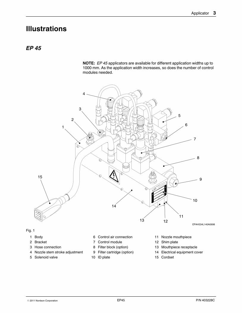
NOTE: EP 45 applicators are available for different application widths up to1000 mm. As the application width increases, so does the number of controlmodules needed.
EPAH334L140A0698
6
9
8
1113 12
10
1
14
15
2
7
3
4
5
Fig. 1
1 Body2 Bracket3 Hose connection4 Nozzle stem stroke adjustment5 Solenoid valve
6 Control air connection7 Control module8 Filter block (option)9 Filter cartridge (option)
10 ID plate
11 Nozzle mouthpiece12 Shim plate13 Mouthpiece receptacle14 Electrical equipment cover15 Cordset
4 Applicator
P/N 403228C � 2011 Nordson CorporationEP45
Illustrations (contd.)
EP 45 with Recirculation Control Module
1
2
3
7
5
4
EPAH140M084A0597
6
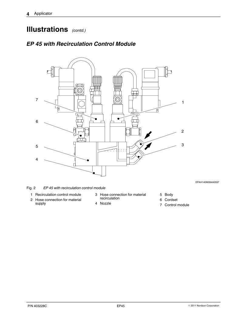
Fig. 2 EP 45 with recirculation control module
1 Recirculation control module2 Hose connection for material
supply
3 Hose connection for materialrecirculation
4 Nozzle
5 Body6 Cordset7 Control module
Applicator 5
P/N 403228C� 2011 Nordson Corporation EP45
FunctionThe applicators in the series EP 45 are used for continuous and intermittentcoating of open-pore and closed-pore substrates with hot melt adhesives.The exchangeable surface nozzles or mouthpieces are available in standardapplication widths up to 500 mm, or up to 1000 mm as special models.
The material flows from the melter through the heated hose, then into theapplicator. From there it passes through distribution channels and into thenozzle. The application widths and patterns can be modified to suit the needsof the specific application by inserting shim plates / masks (12 , Fig. 1).
The control module and body are separate from one another. This enablestemperatures of 200 °C / 392 °F or 260 °C / 500 °F (high temperature orT‐version) to be maintained over longer periods of time.
Electrical heater cartridges are used to heat the unit. The temperature iscontinuously measured by a temperature sensor and regulated by anelectronic temperature controller located in the electrical cabinet of themelter.
Recirculation control modules (Refer to Fig. 2) enable the material pressurein the applicator to be maintained at a constant value. When the controlmodules close and no material is applied, the recirculation control modulesopen, allowing the material to flow back into the melter tank.
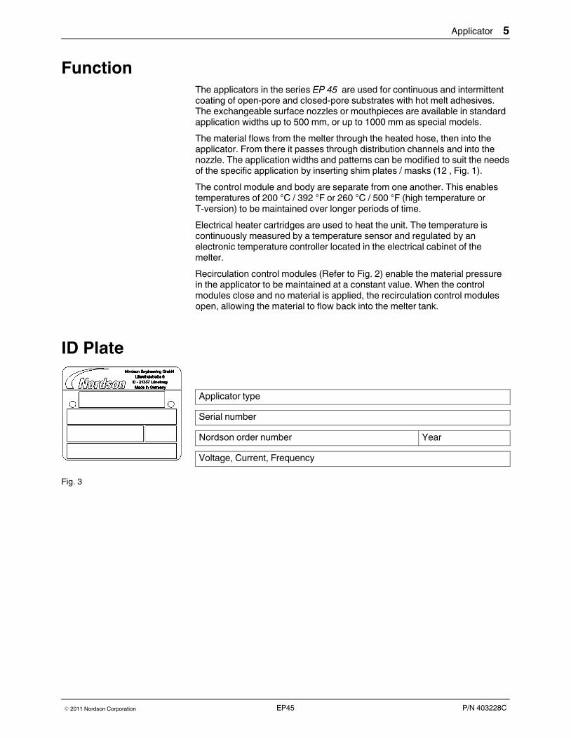
ID Plate
Applicator type
Serial number
Nordson order number Year
Voltage, Current, Frequency
Fig. 3
6 Applicator
P/N 403228C � 2011 Nordson CorporationEP45
InstallationWARNING: Allow only qualified personnel to perform the following tasks.Observe and follow the safety instructions in this document and all otherrelated documentation.
UnpackingUnpack carefully. Then check for damage caused during transport. Reusepackaging materials or dispose of properly according to local regulations.
TransportThe applicator is a high precision, valuable part. Handle very carefully!Protect the nozzle from damage.
InstallingInstall the applicator in the appropriate place in the production machine.Observe the following:
� Do not operate in a potentially explosive atmosphere
� Protect from humidity, vibrations, dust and drafts
� Ensure access to parts relevant for maintenance and operation
� Protect the nozzle from damage.
Exhausting Material Vapors
Ensure that material vapors do not exceed the prescribed limits. Exhaustmaterial vapors when necessary. Provide sufficient ventilation of the locationwhere the unit is installed.
StorageDo not store outside! Protect from humidity and dust. Do not lay unit on thenozzle. Protect the nozzle from damage.
DisposalWhen your Nordson product has exhausted its purpose and/or is no longerneeded, dispose of it properly according to local regulations.
21
Applicator 7
P/N 403228C� 2011 Nordson Corporation EP45
Electrical ConnectionWARNING: Risk of electrical shock. Failure to observe may result inpersonal injury, death, or equipment damage.
Laying Cable
WARNING: Ensure that cables do not touch rotating and/or hotcomponents. Do not pinch cables and check regularly for damage. Replacedamaged cables immediately!
Connecting Applicator
WARNING: Operate the applicator only at the operating voltage shown onthe ID plate.
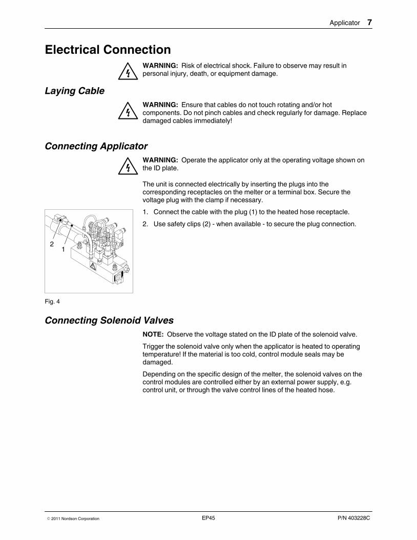
The unit is connected electrically by inserting the plugs into thecorresponding receptacles on the melter or a terminal box. Secure thevoltage plug with the clamp if necessary.
1. Connect the cable with the plug (1) to the heated hose receptacle.
2. Use safety clips (2) - when available - to secure the plug connection.
Fig. 4
Connecting Solenoid Valves
NOTE: Observe the voltage stated on the ID plate of the solenoid valve.
Trigger the solenoid valve only when the applicator is heated to operatingtemperature! If the material is too cold, control module seals may bedamaged.
Depending on the specific design of the melter, the solenoid valves on thecontrol modules are controlled either by an external power supply, e.g.control unit, or through the valve control lines of the heated hose.
1
8 Applicator
P/N 403228C � 2011 Nordson CorporationEP45
Pneumatic ConnectionThe applicator may only be connected to pressure-controlled andconditioned compressed air.
NOTE: The control air must either be lubricated or may not be lubricated atall. Please carefully follow the instructions in the chapter Lubricated orNon-lubricated Control Air.
Compressed Air Filter (Accessory)
Safe operation and service life of pneumatically driven applicators essentiallydepend on conditioning of the compressed air. Dust or condensation willincrease the wear on sliding surfaces and sealing elements, thereby causingdamage. Thus the compressed air should be conditioned with a compressedair filter with water separator. The air conditioning unit cleans and dries thecompressed air.
NOTE: The filter mesh size may not exceed 40 µm.
Connecting Control Air
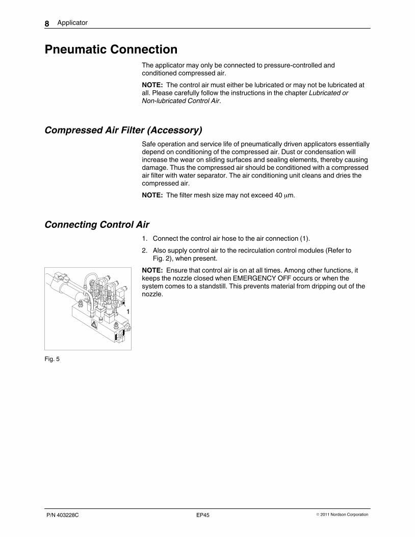
1. Connect the control air hose to the air connection (1).
2. Also supply control air to the recirculation control modules (Refer toFig. 2), when present.
NOTE: Ensure that control air is on at all times. Among other functions, itkeeps the nozzle closed when EMERGENCY OFF occurs or when thesystem comes to a standstill. This prevents material from dripping out of thenozzle.
Fig. 5

Applicator 9
P/N 403228C� 2011 Nordson Corporation EP45
Lubricated or Non‐lubricated Control Air
Applicators in the series EP 45 built in 1997 or later can be operated witheither lubricated or non‐lubricated compressed air. To accommodate this, thecontrol modules are modified in the following way:
� Control module cylinder has a special interior coating
� O-rings (on the piston) with increased Shore hardness.
NOTE: Once the air has been lubricated, it must always be lubricated; thelubricated compressed air will wash out the original lubricant on the solenoidvalves and the control modules.
The new control modules can be identified by a circumferential groove(arrow, Fig. 6).
Fig. 6
When control modules / applicators of the new design are connected to acompressed air system in which the compressed air has previously beenlubricated, simply ceasing to lubricate the air is not sufficient. The oilremaining in the compressed air supply will reach the solenoid valves andthe control modules and wash out the original lubricant/oil from these parts,substantially decreasing the service life of the units.
To operate with non‐lubricated control air, ensure that:
� The system has been converted to absolutely non‐lubricated operation
� No oil from a possibly defective compressor can penetrate thecompressed air supply.
� Control air is on at all times. It keeps the control modules closed whenEMERGENCY OFF occurs or when the system comes to a standstill.This prevents material from dripping out of the nozzle.
NOTE: Nordson will assume no warranty or liability for damage caused byunpermitted, temporary lubrication.
Operating with Lubricated Control Air
The applicators / control modules of the new design can also be operatedwith lubricated compressed air.
NOTE: Once the air has been lubricated, it must always be lubricated; thelubricated compressed air will wash out the original lubricant on the solenoidvalves and the control modules. Only the following oil may be used:
Oil P/N
Klüber Unisilkon TK 002/100 253 700
1 2 3
10 Applicator
P/N 403228C � 2011 Nordson CorporationEP45
Connecting Heated HoseWARNING: Hot! Risk of burns. Wear heat‐protective gloves.
Using Second Open‐end Wrench
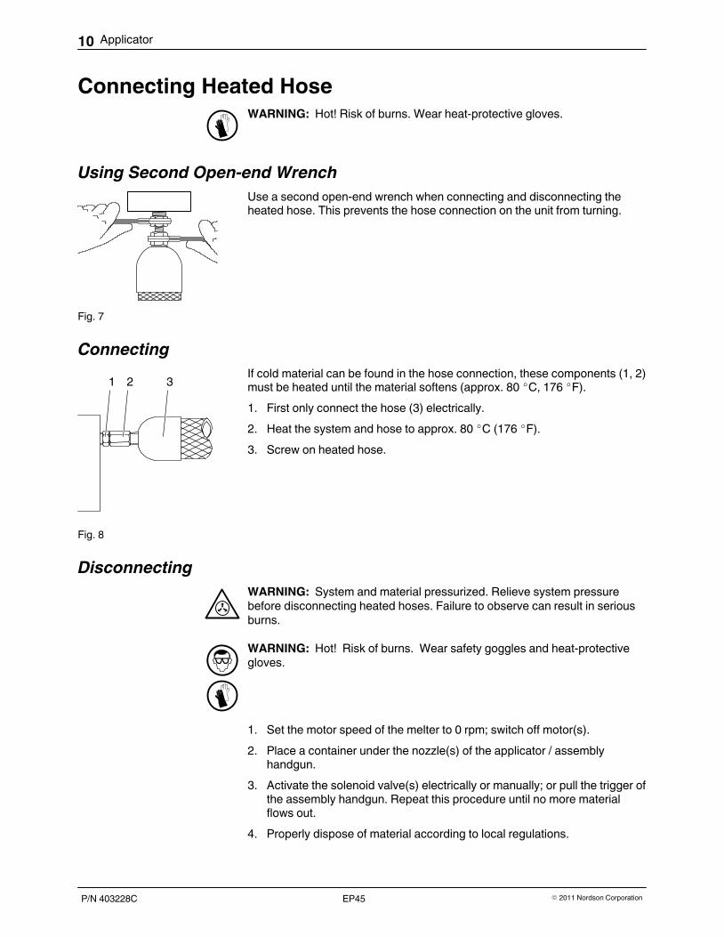
Use a second open‐end wrench when connecting and disconnecting theheated hose. This prevents the hose connection on the unit from turning.
Fig. 7
Connecting
If cold material can be found in the hose connection, these components (1, 2)must be heated until the material softens (approx. 80 �C, 176 �F).
1. First only connect the hose (3) electrically.
2. Heat the system and hose to approx. 80 �C (176 �F).
3. Screw on heated hose.
Fig. 8
Disconnecting
WARNING: System and material pressurized. Relieve system pressurebefore disconnecting heated hoses. Failure to observe can result in seriousburns.
WARNING: Hot! Risk of burns. Wear safety goggles and heat‐protectivegloves.
1. Set the motor speed of the melter to 0 rpm; switch off motor(s).
2. Place a container under the nozzle(s) of the applicator / assemblyhandgun.
3. Activate the solenoid valve(s) electrically or manually; or pull the trigger ofthe assembly handgun. Repeat this procedure until no more materialflows out.
4. Properly dispose of material according to local regulations.
Applicator 11
P/N 403228C� 2011 Nordson Corporation EP45
OperationWARNING: Allow only qualified personnel to perform the following tasks.Observe and follow the safety instructions in this document and all otherrelated documentation.
Important When Using Polyurethane ApplicationMaterials (PUR)
It is imperative that the following guidelines are followed when processingpolyurethane application materials (PUR):
� Wear respiratory protection when the maximum permissibleconcentration of hazardous substances is exceeded.
� Before prolonged standstill of the application system, purge with asuitable cleaning agent. Use only a cleaning agent recommended by thematerial manufacturer.
� Close open material connections airtight.
When the system is to cease operation for only a short time, it suffices to coatthe application slot generously with grease.
CAUTION: Use only special high‐temperature grease. Refer to page 33,Processing Materials! Any other grease may cause the PUR material tocross‐link.
Triggering Solenoid ValvesWARNING: Operate only at the operating voltage shown on the ID plate.
CAUTION: Trigger the solenoid valves only when the applicator is heated tooperating temperature! Seals in the application control module and therecirculation control module can become damaged if the material is too cold.

12 Applicator
P/N 403228C � 2011 Nordson CorporationEP45
Setting Temperature
The procedure for setting the temperatures is described in the temperaturecontroller manual. Temperature controllers are not part of the applicator.They can be located e.g. in the electrical cabinet of the melter or in aseparate electrical cabinet.
Maximum Operating Temperature
200 ° C / 392 ° F; 260 ° C / 500 ° F with high temperature version
NOTE: The maximum operating temperature may not be exceeded.
Nordson will grant no warranty and assume no liability for damage resultingfrom incorrect temperature settings.
Setting Control Air PressureThe control air pressure for the control module is set for each application onan external air pressure control valve. The air pressure control valve is notpart of the applicator.
NOTE: Ensure that the applicator is supplied with control air at all times. Thecontrol air keeps the control modules closed when EMERGENCY OFFoccurs or when the system comes to a standstill. This prevents material fromdripping out of the nozzle.
Maximum Control Air Pressure
6 bar / 0.6 MPa / 87 psi
NOTE: The maximum control air pressure may not be exceeded.
Nordson will assume no warranty or liability for damage caused by anincorrect pressure setting.
XXAH157S130A0797
Max. + 1.2mmMax. +0.047 in.
Max. + 1.2mmMax. +0.047 in.
1
23
4
Applicator 13
P/N 403228C� 2011 Nordson Corporation EP45
Setting Material Application QuantityThe material quantity needed depends on the desired grammage and on thesubstrate speed. It is usually preselected using the pump speed dials. Theoptimum setting must be determined by trial and error.
The speed dials are located e.g. in the electrical cabinet of a melter or in aseparate electrical cabinet.
Depending on the model of the material application system, pump speedcontrol can also occur with a tach generator or an electronic pressurecontroller.
Setting Nozzle Stem Stroke
All control modules are equipped with a nozzle stem stroke adjustment. It isused for fine adjustment of the material application quantity or the materialflow quantity.
WARNING: Hazard! The stem stroke adjustment knob has no upper settinglimit. If compressed air is connected, never completely turn up theadjustment knob / adjustment screw; it may jump out.
CAUTION: The nozzle stem stroke may be adjusted only when theapplicator is heated! Failure to observe can cause damage to seals.
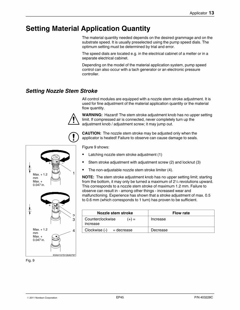
Figure 9 shows:
� Latching nozzle stem stroke adjustment (1)
� Stem stroke adjustment with adjustment screw (2) and locknut (3)
� The non‐adjustable nozzle stem stroke limiter (4).
NOTE: The stem stroke adjustment knob has no upper setting limit; startingfrom the bottom, it may only be turned a maximum of 2¼ revolutions upward.This corresponds to a nozzle stem stroke of maximum 1.2 mm. Failure toobserve can result in - among other things - increased wear andmalfunctioning. Experience has shown that a stroke adjustment of max. 0.5to 0.6 mm (which corresponds to 1 turn) has proven to be sufficient.
Nozzle stem stroke Flow rate
Counterclockwise (+) =increase
Increase
Clockwise (-) = decrease Decrease
Fig. 9
14 Applicator
P/N 403228C � 2011 Nordson CorporationEP45
Positioning ApplicatorSince the optimum angle of incidence of the applicator is a factor of variouscustomerĆspecific parameters, the angle can not be determined preciselybeforehand. However, it must be at or about 90° .
NOTE: The ideal application position should always first be determined bytrial and error!
Angle of Incidence
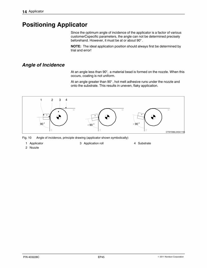
At an angle less than 90°, a material bead is formed on the nozzle. When thisoccurs, coating is not uniform.
At an angle greater than 90° , hot melt adhesive runs under the nozzle andonto the substrate. This results in uneven, flaky application.
90
1 2 3 4
90 90
CTSY096L045A1195
Fig. 10 Angle of incidence, principle drawing (applicator shown symbolically)
1 Applicator2 Nozzle
3 Application roll 4 Substrate
Applicator 15
P/N 403228C� 2011 Nordson Corporation EP45
Positioning Applicator (contd.)
Height / Contact Line and Parallelism
NOTE: The optimum position of the applicator depends on several factors ofthe customer's specific application. Thus trial and error is the only way todetermine the best position. The fundamental differences are:
� Application of material to open‐pore substrate
� Application of material to closed‐pore substrate
CTSY097L045B0997
1 2 3 4 1 2 3 4
55
Open-pored substrate Closed-pored substrate
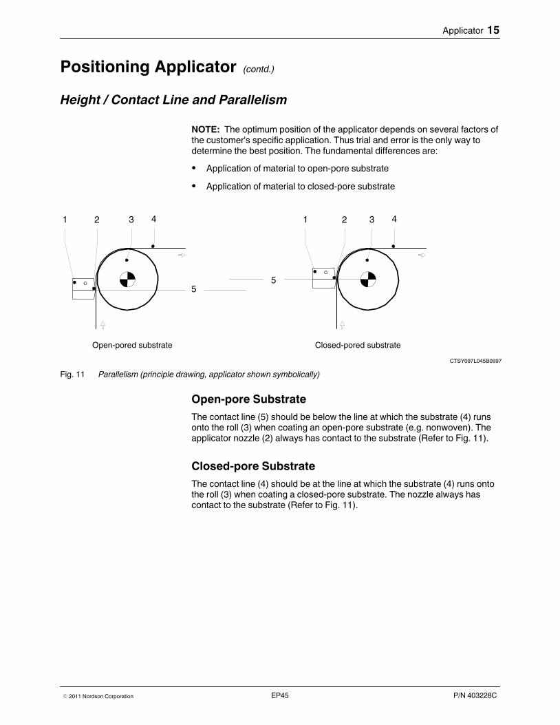
Fig. 11 Parallelism (principle drawing, applicator shown symbolically)
Open-pore Substrate
The contact line (5) should be below the line at which the substrate (4) runsonto the roll (3) when coating an open‐pore substrate (e.g. nonwoven). Theapplicator nozzle (2) always has contact to the substrate (Refer to Fig. 11).
Closed‐pore Substrate
The contact line (4) should be at the line at which the substrate (4) runs ontothe roll (3) when coating a closed‐pore substrate. The nozzle always hascontact to the substrate (Refer to Fig. 11).
16 Applicator
P/N 403228C � 2011 Nordson CorporationEP45
Operation
EPAH214L147A0997
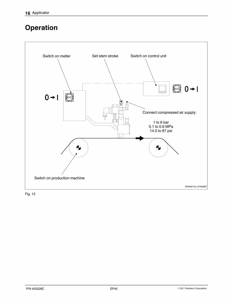
Switch on melter Set stem stroke Switch on control unit
Switch on production machine
1 to 6 bar0.1 to 0.6 MPa14.5 to 87 psi
Connect compressed air supply:
Fig. 12
Applicator 17
P/N 403228C� 2011 Nordson Corporation EP45
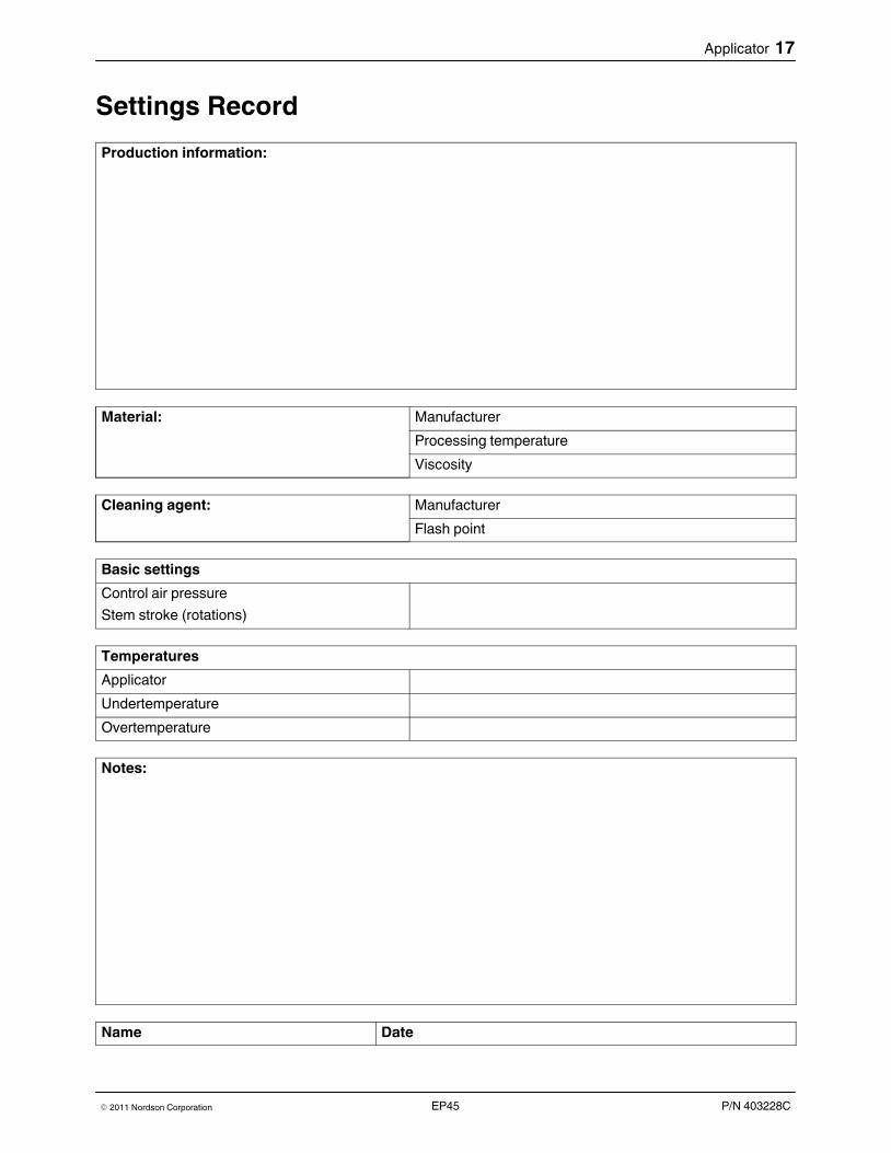
Settings Record
Production information:
Material: Manufacturer
Processing temperature
Viscosity
Cleaning agent: Manufacturer
Flash point
Basic settings
Control air pressure
Stem stroke (rotations)
Temperatures
Applicator
Undertemperature
Overtemperature
Notes:
Name Date
18 Applicator
P/N 403228C � 2011 Nordson CorporationEP45
MaintenanceWARNING: Allow only qualified personnel to perform the following tasks.Observe and follow the safety instructions in this document and all otherrelated documentation.
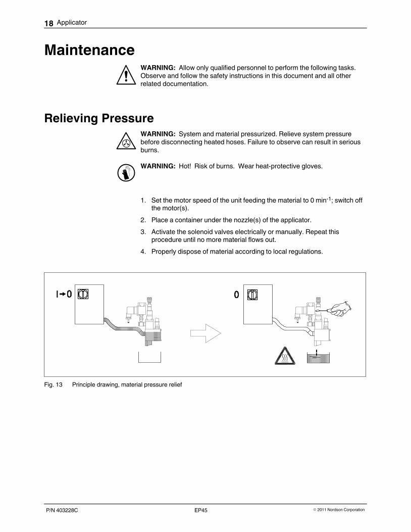
Relieving PressureWARNING: System and material pressurized. Relieve system pressurebefore disconnecting heated hoses. Failure to observe can result in seriousburns.
WARNING: Hot! Risk of burns. Wear heat‐protective gloves.
1. Set the motor speed of the unit feeding the material to 0 min‐1; switch offthe motor(s).
2. Place a container under the nozzle(s) of the applicator.
3. Activate the solenoid valves electrically or manually. Repeat thisprocedure until no more material flows out.
4. Properly dispose of material according to local regulations.
Fig. 13 Principle drawing, material pressure relief
Applicator 19
P/N 403228C� 2011 Nordson Corporation EP45
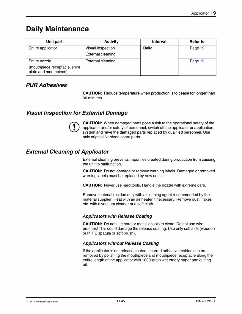
Daily Maintenance
Unit part Activity Interval Refer to
Entire applicator Visual inspection
External cleaning
Daily Page 19
Entire nozzle
(mouthpiece receptacle, shimplate and mouthpiece)
External cleaning Page 19
PUR Adhesives
CAUTION: Reduce temperature when production is to cease for longer than30 minutes.
Visual Inspection for External Damage
CAUTION: When damaged parts pose a risk to the operational safety of theapplicator and/or safety of personnel, switch off the applicator or applicationsystem and have the damaged parts replaced by qualified personnel. Useonly original Nordson spare parts.
External Cleaning of Applicator
External cleaning prevents impurities created during production from causingthe unit to malfunction.
CAUTION: Do not damage or remove warning labels. Damaged or removedwarning labels must be replaced by new ones.
CAUTION: Never use hard tools. Handle the nozzle with extreme care.
Remove material residue only with a cleaning agent recommended by thematerial supplier. Heat with an air heater if necessary. Remove dust, flakesetc. with a vacuum cleaner or a soft cloth.
Applicators with Release Coating
CAUTION: Do not use hard or metallic tools to clean. Do not use wire brushes! This could damage the release coating. Use only soft aids (wooden or PTFE spatula or soft brush).
Applicators without Release Coating
If the applicator is not release coated, charred adhesive residue can beremoved by polishing the mouthpiece and mouthpiece receptacle along theentire length of the applicator with 1000‐grain wet emery paper and cuttingoil.
20 Applicator
P/N 403228C � 2011 Nordson CorporationEP45
External Cleaning of Nozzle
CAUTION: Clean the nozzle very carefully, and never use hard or metallictools. A damaged nozzle will result in uneven material application, and it willneed to be repaired.
WARNING: Hot! Risk of burns. Wear heat‐protective gloves.
1. Remove material residue from the nozzle promptly with a soft cloth,before it chars.
2. Remove tough and hardened residue with a wooden or PTFE spatula if necessary.
Nozzle with Release Coating
Refer to page 19, Applicator with Release Coating.
Nozzle without Release Coating
Refer to page 19, Applicator without Release Coating.
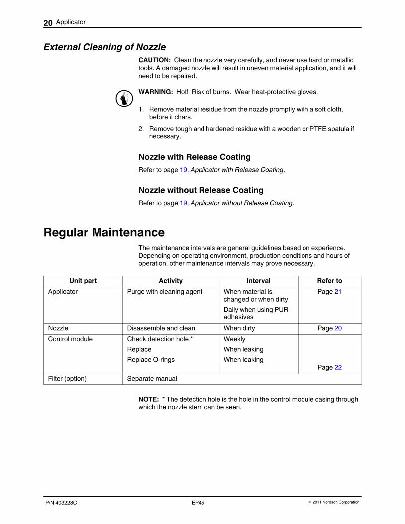
Regular MaintenanceThe maintenance intervals are general guidelines based on experience.Depending on operating environment, production conditions and hours ofoperation, other maintenance intervals may prove necessary.
Unit part Activity Interval Refer to
Applicator Purge with cleaning agent When material ischanged or when dirty
Daily when using PURadhesives
Page 21
Nozzle Disassemble and clean When dirty Page 20
Control module Check detection hole *
Replace
Replace O-rings
Weekly
When leaking
When leakingPage 22
Filter (option) Separate manual
NOTE: * The detection hole is the hole in the control module casing throughwhich the nozzle stem can be seen.
1
Applicator 21
P/N 403228C� 2011 Nordson Corporation EP45
Changing Type of Material
NOTE: Before changing the type of material, determine whether the old andnew material may be mixed.
� May be mixed: Remaining old material can be flushed out using the newmaterial.
� May not be mixed: Thoroughly purge the unit with a cleaning agentrecommended by the material supplier.
NOTE: Properly dispose of the material and cleaning agent according tolocal regulations.
Purging with Cleaning Agent
CAUTION: Use only a cleaning agent recommended by the hot meltmaterial manufacturer. Observe the Material Safety Data Sheet for thecleaning agent.
NOTE: When PUR adhesive is used, it must be prevented from reacting tothe thermal load in the applicator. The applicator must be purged every daywhen work is completed. Rinse out cleaning agent just before beginningproduction again.
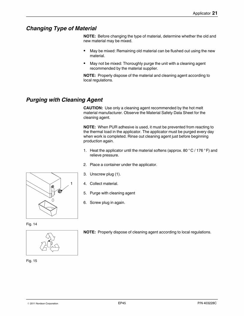
1. Heat the applicator until the material softens (approx. 80 ° C / 176 ° F) andrelieve pressure.
2. Place a container under the applicator.
3. Unscrew plug (1).
4. Collect material.
5. Purge with cleaning agent
6. Screw plug in again.
Fig. 14
NOTE: Properly dispose of cleaning agent according to local regulations.
Fig. 15
22 Applicator
P/N 403228C � 2011 Nordson CorporationEP45
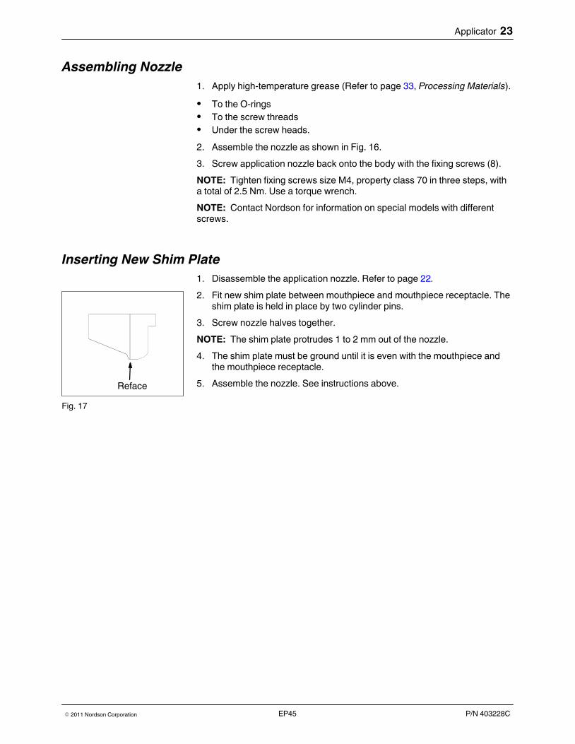
Disassembling and Cleaning Nozzle
1. Heat applicator until material is soft.
2. Detach and disassemble nozzle (Refer to Fig. 16).
3. Insert forcing screws to separate the mouthpiece and mouthpiecereceptacle from one another.
4. Use suitable tools to remove charred material from holes and channels.
5. If necessary, polish body and mouthpiece sealing surfaces with1000‐grain wet emery paper and cutting oil (metal working oil).
6. Use a cleaning agent to dissolve material residue that could not beremoved mechanically.
NOTE: Properly dispose of cleaning agent, material residue and cutting oilaccording to local regulations.
CAUTION: Only use a cleaning agent recommended by the materialsupplier. Observe Manufacturer Safety Data Sheet (MSDS) for the cleaningagent.
3 mm
3 mm
3 mm
Fig. 16
Reface
Applicator 23
P/N 403228C� 2011 Nordson Corporation EP45
Assembling Nozzle
1. Apply high-temperature grease (Refer to page 33, Processing Materials).
� To the O-rings� To the screw threads� Under the screw heads.
2. Assemble the nozzle as shown in Fig. 16.
3. Screw application nozzle back onto the body with the fixing screws (8).
NOTE: Tighten fixing screws size M4, property class 70 in three steps, witha total of 2.5 Nm. Use a torque wrench.
NOTE: Contact Nordson for information on special models with differentscrews.
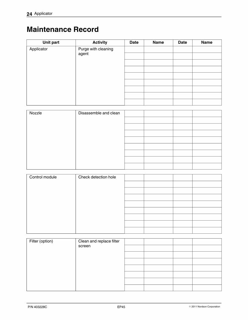
Inserting New Shim Plate
1. Disassemble the application nozzle. Refer to page 22.
2. Fit new shim plate between mouthpiece and mouthpiece receptacle. Theshim plate is held in place by two cylinder pins.
3. Screw nozzle halves together.
NOTE: The shim plate protrudes 1 to 2 mm out of the nozzle.
4. The shim plate must be ground until it is even with the mouthpiece andthe mouthpiece receptacle.
5. Assemble the nozzle. See instructions above.
Fig. 17
24 Applicator
P/N 403228C � 2011 Nordson CorporationEP45
Maintenance Record
Unit part Activity Date Name Date Name
Applicator Purge with cleaningagent
Nozzle Disassemble and clean
Control module Check detection hole
Filter (option) Clean and replace filterscreen

Applicator 25
P/N 403228C� 2011 Nordson Corporation EP45
Repair / RetrofittingWARNING: Allow only qualified personnel to perform the following tasks.Observe and follow the safety instructions in this document and all otherrelated documentation.
Modifying Applicator for New Control ModulesApplicators in the series EP 45 built in 1997 or later can be operated witheither lubricated or non‐lubricated compressed air. If older applicators are tobe retrofitted for operation with non-lubricated compressed air, the controlmodules have to be replaced.
If an old applicator is to be retrofitted with new control modules to enableoperation with non-lubricated compressed air, the following measures mustbe performed:
� Replace the control module with a control module of the new design
� Replace the solenoid valve
� Change the compressed air supply to absolutely oil-free operation
� Set the nozzle stem stroke (Refer to page 13, Setting Nozzle Stem
Stroke� ).
Replacing Single Control ModulesIf some but not all of the control modules on an applicator are replaced withcontrol modules of the new design, the applicator must continue to beoperated with lubricated compressed air. The following oils may be used:
Oil P/N
Klüber Unisilkon TK 002/100 253 700
Klüber Unisilkon TK002/50 316 578

26 Applicator
P/N 403228C � 2011 Nordson CorporationEP45
Retrofitting Control ModuleIf a control module is to be retrofitted to enable operation with non-lubricatedcompressed air, the following measures must be performed:
� Remove control module (See below, Removing Control Module andpage 29, Installing Control Module).
� Disassemble control module (Refer to page 27)
� Replace the cylinder (Refer to page 28, Overview of Parts)
� Replace and oil the O-rings on the piston (Refer to page 28, Overview of
Parts and Lubricating O-rings)
� Replace all solenoid valves
� Change the compressed air supply to absolutely oil-free operation
� Set the nozzle stem stroke (Refer to page 13, Setting Nozzle Stem
Stroke� ).
Removing Control ModuleWARNING: Hot! Risk of burns. Wear heat‐protective gloves.
1. Disconnect compressed air hoses.
2. Heat the applicator until the material is soft.
3. Release fixing screws and detach control module.
Fig. 18
1
3
4
5
7
6
8
9
2
2
1
2
2
1
2
2
Applicator 27
P/N 403228C� 2011 Nordson Corporation EP45
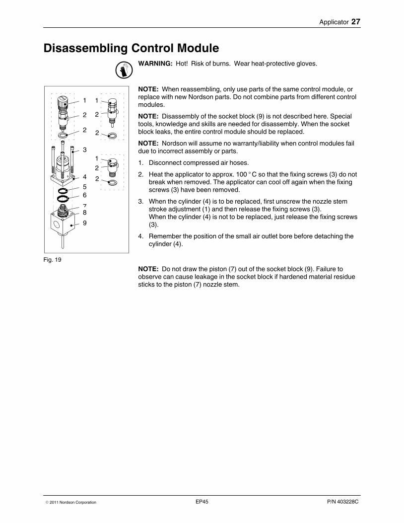
Disassembling Control ModuleWARNING: Hot! Risk of burns. Wear heat‐protective gloves.
NOTE: When reassembling, only use parts of the same control module, orreplace with new Nordson parts. Do not combine parts from different controlmodules.
NOTE: Disassembly of the socket block (9) is not described here. Specialtools, knowledge and skills are needed for disassembly. When the socketblock leaks, the entire control module should be replaced.
NOTE: Nordson will assume no warranty/liability when control modules faildue to incorrect assembly or parts.
1. Disconnect compressed air hoses.
2. Heat the applicator to approx. 100 ° C so that the fixing screws (3) do notbreak when removed. The applicator can cool off again when the fixingscrews (3) have been removed.
3. When the cylinder (4) is to be replaced, first unscrew the nozzle stemstroke adjustment (1) and then release the fixing screws (3).When the cylinder (4) is not to be replaced, just release the fixing screws(3).
4. Remember the position of the small air outlet bore before detaching thecylinder (4).
Fig. 19
NOTE: Do not draw the piston (7) out of the socket block (9). Failure toobserve can cause leakage in the socket block if hardened material residuesticks to the piston (7) nozzle stem.
28 Applicator
P/N 403228C � 2011 Nordson CorporationEP45
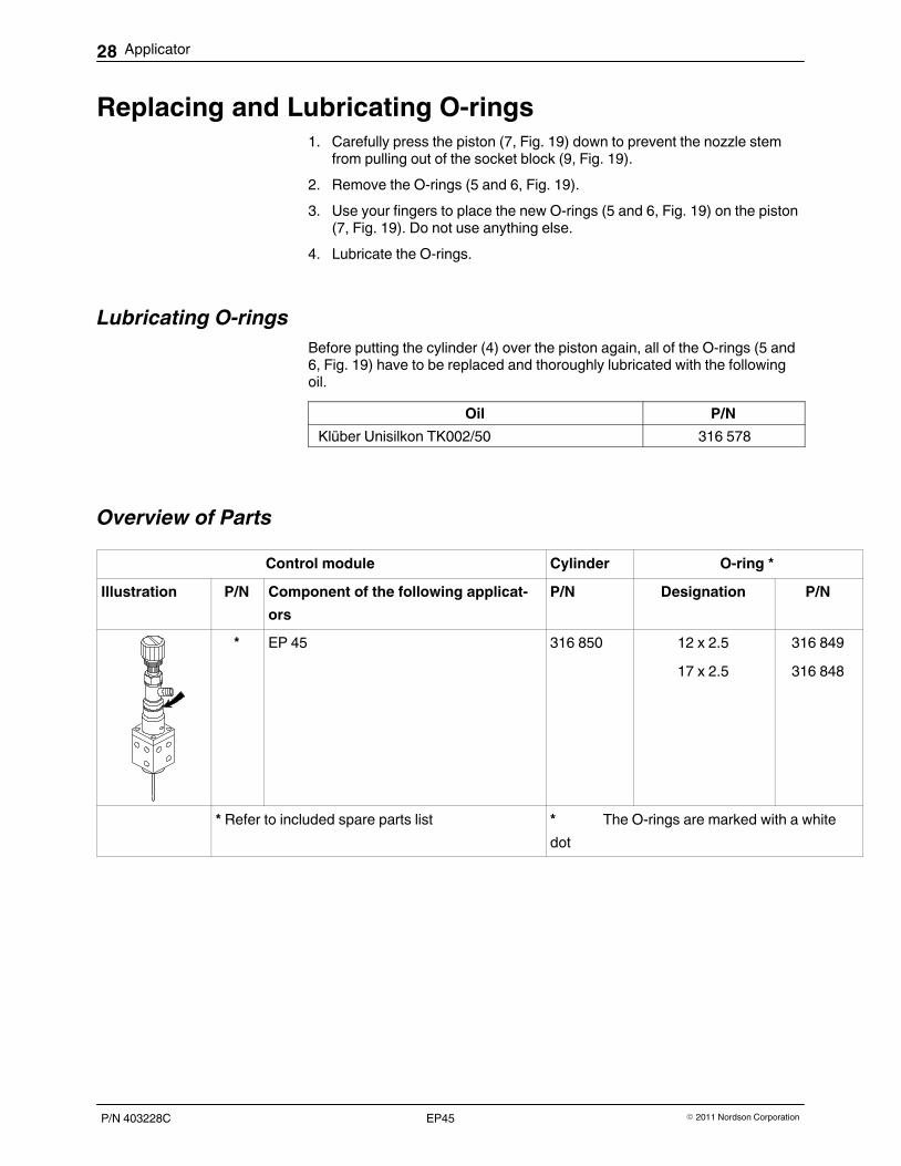
Replacing and Lubricating O-rings1. Carefully press the piston (7, Fig. 19) down to prevent the nozzle stem
from pulling out of the socket block (9, Fig. 19).
2. Remove the O‐rings (5 and 6, Fig. 19).
3. Use your fingers to place the new O-rings (5 and 6, Fig. 19) on the piston(7, Fig. 19). Do not use anything else.
4. Lubricate the O‐rings.
Lubricating O‐rings
Before putting the cylinder (4) over the piston again, all of the O‐rings (5 and6, Fig. 19) have to be replaced and thoroughly lubricated with the followingoil.
Oil P/N
Klüber Unisilkon TK002/50 316 578
Overview of Parts
Control module Cylinder O-ring *
Illustration P/N Component of the following applicat
ors
P/N Designation P/N
* EP 45 316 850 12 x 2.5
17 x 2.5
316 849
316 848
* Refer to included spare parts list * The O‐rings are marked with a white
dot

1
3
4
5
7
6
8
9
2
2
1
2
2
1
2
2
3 mm
Applicator 29
P/N 403228C� 2011 Nordson Corporation EP45
Assembling Control Module1. If the stem stroke adjustment (1) was detached from the cylinder (4),
screw it back on. Replace the sealing rings (2). Order number P/N 251428.
2. Replace the O‐ring (8).
3. Verify that the O‐rings (5 and 6) have been lubricated with the prescribedoil (Refer to page 28, Lubricating O‐Rings).
4. Carefully draw the cylinder (4) over the piston (7). Ensure that the smallair outlet bore is in the same place as is was before the cylinder wasremoved.
5. Apply mounting paste to the threads of the fixing screws (3), if possible.This is intended to prevent the thread from sticking. Mounting paste:Never Seez, order number: P/N 263 921
6. Tighten the fixing screws (3) evenly crosswise.
7. Restore compressed air connections.
8. If the the nozzle stem stroke was adjusted, set it (Refer to page13,Setting Nozzle Stem Stroke�).
Fig. 20
Installing Control Module1. Heat the applicator until the material is soft.
2. Apply mounting paste to the threads of the fixing screws, if possible. Thisis intended to prevent the thread from sticking. Mounting paste: NeverSeez, order number: P/N 263 921
3. Replace the O‐ring(s); order number P/N 250 257.
4. Insert the new control module in the applicator and tighten screwsalternately or crosswise.
Fig. 21
30 Applicator
P/N 403228C � 2011 Nordson CorporationEP45
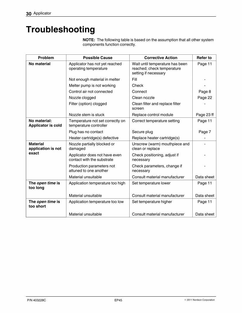
TroubleshootingNOTE: The following table is based on the assumption that all other systemcomponents function correctly.
Problem Possible Cause Corrective Action Refer to
No material Applicator has not yet reachedoperating temperature
Wait until temperature has beenreached; check temperaturesetting if necessary
Page 11
Not enough material in melter Fill ‐
Melter pump is not working Check ‐
Control air not connected Connect Page 8
Nozzle clogged Clean nozzle Page 22
Filter (option) clogged Clean filter and replace filterscreen
‐
Nozzle stem is stuck Replace control module Page 23 ff
No material:Applicator is cold
Temperature not set correctly ontemperature controller
Correct temperature setting Page 11
Plug has no contact Secure plug Page 7
Heater cartridge(s) defective Replace heater cartridge(s) ‐
Materialapplication is notexact
Nozzle partially blocked ordamaged
Unscrew (warm) mouthpiece andclean or replace
‐
Applicator does not have evencontact with the substrate
Check positioning, adjust ifnecessary
‐
Production parameters notattuned to one another
Check parameters, change ifnecessary
‐
Material unsuitable Consult material manufacturer Data sheet
The open time istoo long
Application temperature too high Set temperature lower Page 11
Material unsuitable Consult material manufacturer Data sheet
The open time istoo short
Application temperature too low Set temperature higher Page 11
Material unsuitable Consult material manufacturer Data sheet
Applicator 31
P/N 403228C� 2011 Nordson Corporation EP45
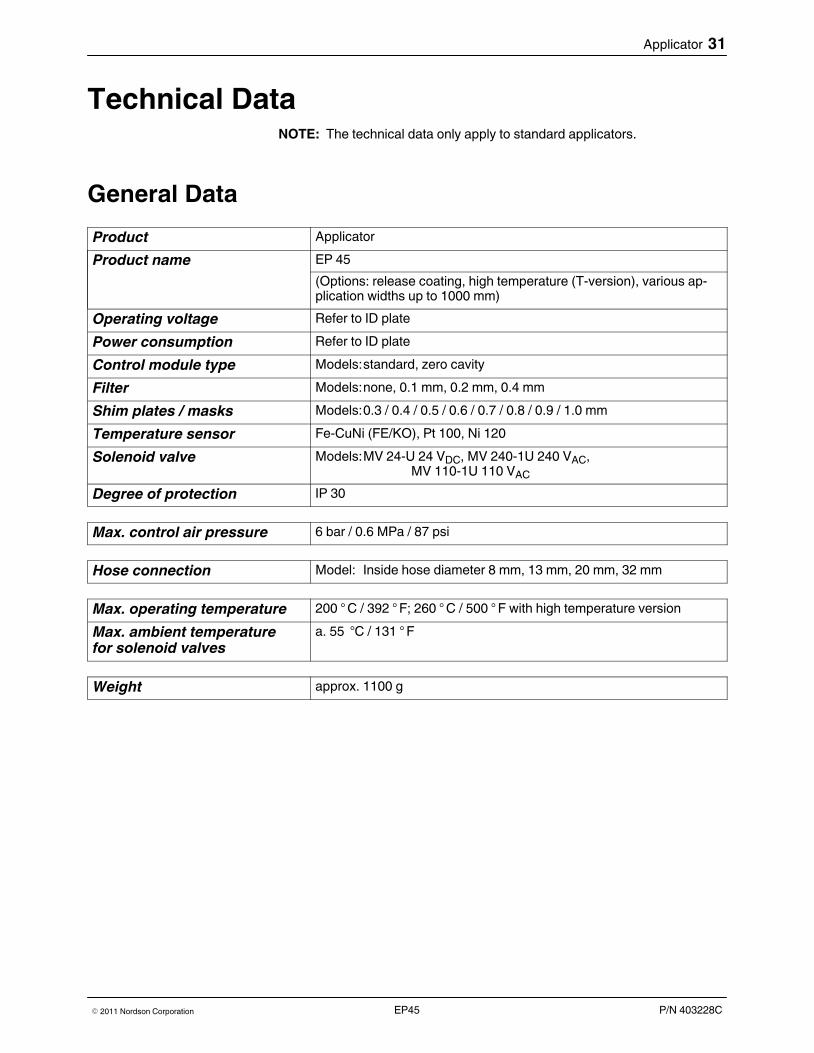
Technical DataNOTE: The technical data only apply to standard applicators.
General Data
Product Applicator
Product name EP 45
(Options: release coating, high temperature (T‐version), various application widths up to 1000 mm)
Operating voltage Refer to ID plate
Power consumption Refer to ID plate
Control module type Models:standard, zero cavity
Filter Models:none, 0.1 mm, 0.2 mm, 0.4 mm
Shim plates / masks Models:0.3 / 0.4 / 0.5 / 0.6 / 0.7 / 0.8 / 0.9 / 1.0 mm
Temperature sensor Fe‐CuNi (FE/KO), Pt 100, Ni 120
Solenoid valve Models:MV 24‐U 24 VDC, MV 240‐1U 240 VAC,MV 110‐1U 110 VAC
Degree of protection IP 30
Max. control air pressure 6 bar / 0.6 MPa / 87 psi
Hose connection Model: Inside hose diameter 8 mm, 13 mm, 20 mm, 32 mm
Max. operating temperature 200 ° C / 392 ° F; 260 ° C / 500 ° F with high temperature version
Max. ambient temperaturefor solenoid valves
a. 55 °C / 131 ° F
Weight approx. 1100 g

32 Applicator
P/N 403228C � 2011 Nordson CorporationEP45
Cordset
2 blue3 brown
4 black
5 black
6 red
7 blue
Heater
Solenoid valve
8 green/yellow Ground conductor
Thermo lead +
Thermo lead -Pin insert HAN 7D KWU
Fig. 22 Power cable for temperature sensor Fe‐CuNi (FE/KO)
2 blue3 brown
4 black
5 black
6 red (black)
7 white (black)
Heater
Solenoid valve
Temperature sensor Pt 100
8 green/yellow Ground conductor
Pin insert HAN 7D KWU
Fig. 23 Power cable for temperature sensor Pt 100
Temperature sensor Ni 12053
1
2
Black
BlackHeater
Ground conductorGreen/yellow
Fig. 24 Power cable with temperature sensor Ni 120
Applicator 33
P/N 403228C� 2011 Nordson Corporation EP45
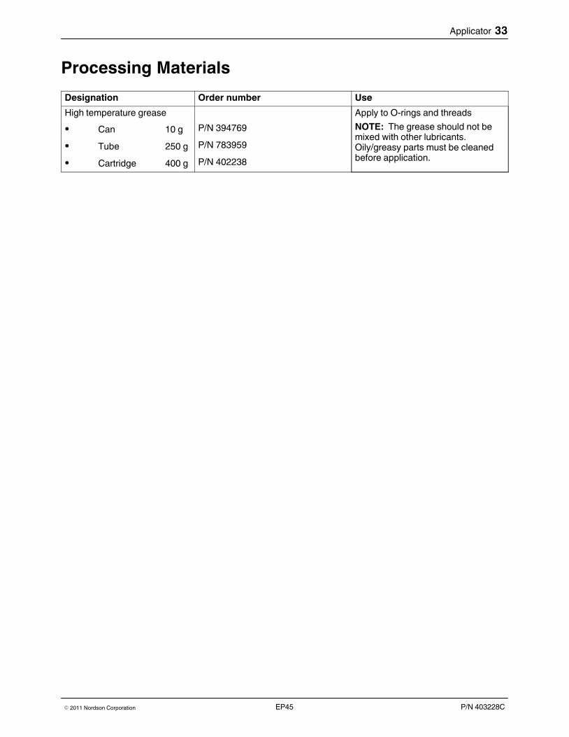
Processing Materials
Designation Order number Use
High temperature grease Apply to O-rings and threads
NOTE: The grease should not bemixed with other lubricants.Oily/greasy parts must be cleanedbefore application.
� Can 10 g P/N 394769
� Tube 250 g P/N 783959
� Cartridge 400 g P/N 402238

34 Applicator
P/N 403228C � 2011 Nordson CorporationEP45