static friction force measurement in mems. introduction mems (micro-electromechanical systems)...
TRANSCRIPT
STATIC FRICTION FORCE MEASUREMENT IN MEMS
Introduction
• MEMS (micro-electromechanical systems) technology holds the promise to revolutionize the microelectronics industry, but reliability problems currently hamper the application of the technology in many fields.
• In MEMS devices involving parts in relative motion to each other.
• Large friction forces become the limiting factor to their successful operation and reliability.
• Common lubricants used in macroscopic systems (such as oil) cannot be applied, because the viscous drag of these substances is so large that it prevents high speeds on the micro-scale, if the devices work at all.
Introduction
• To measure the static friction of a rotor bearing interface in a micromotor Tai and muller measured the starting torque (voltage).
• Friction torque model was used to obtain the coefficient of static friction.
• To measure kinetic friction of turbine and gear structure Gabriel et al. used a laser based measurement system to monitor the steady state spins and decelerations.
• Lim et al. designed and fabricated a polysilicon microstructure to measure the static friction of various films.
• Beerschwinger et al. developed a cantilever deflection rig to measure friction of LIGA processed micromotors.
• A modified atomic force microscope (AFM) is used to perform contact resistance and/or current-dependent stiction measurements for conductive thin films at controlled values
of applied force.
FRICTION FORCE MEASUREMENT
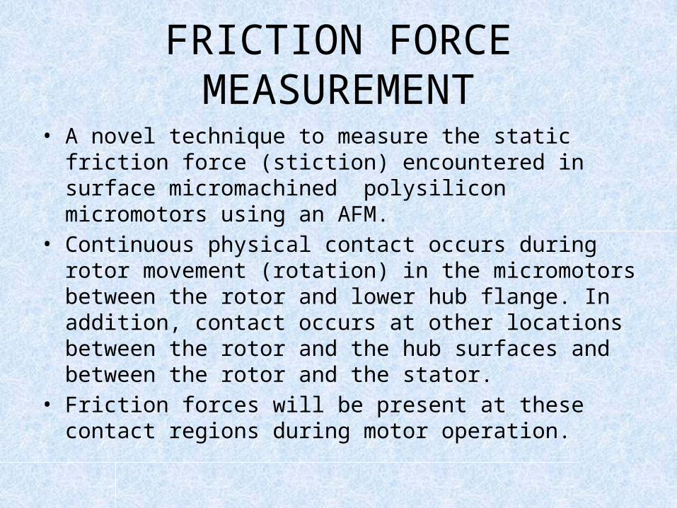
• A novel technique to measure the static friction force (stiction) encountered in surface micromachined polysilicon micromotors using an AFM.
• Continuous physical contact occurs during rotor movement (rotation) in the micromotors between the rotor and lower hub flange. In addition, contact occurs at other locations between the rotor and the hub surfaces and between the rotor and the stator.
• Friction forces will be present at these contact regions during motor operation.
FRICTION FORCE MEASUREMENT
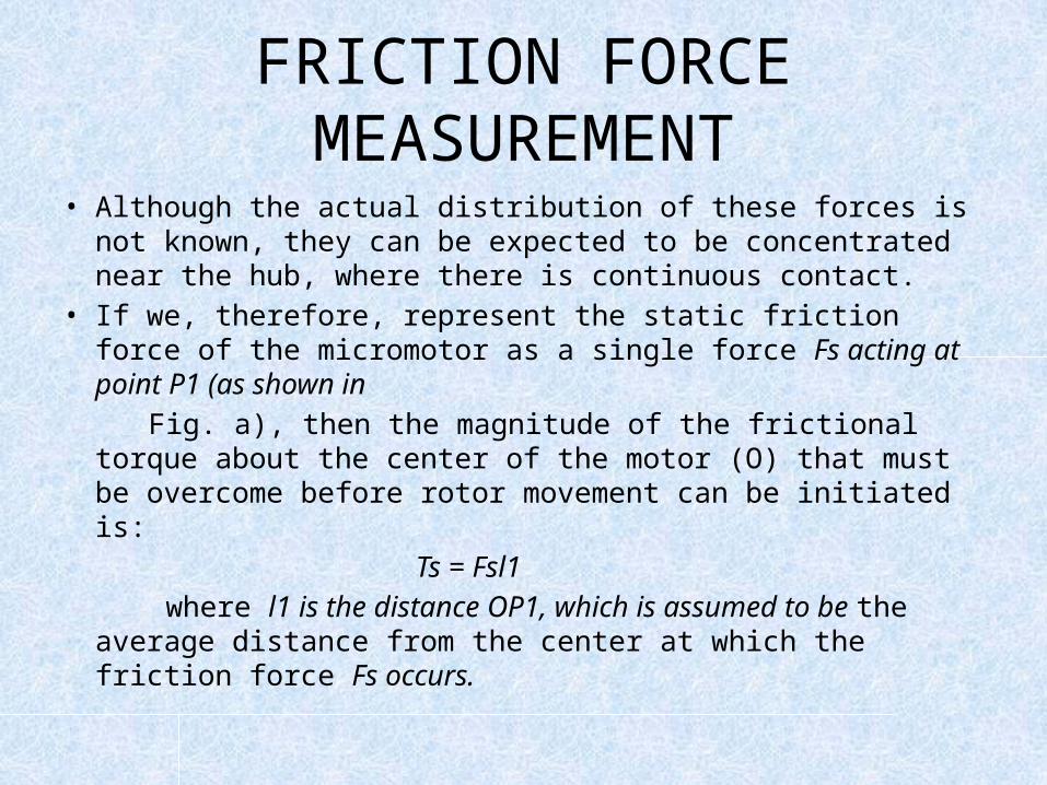
• Although the actual distribution of these forces is not known, they can be expected to be concentrated near the hub, where there is continuous contact.
• If we, therefore, represent the static friction force of the micromotor as a single force Fs acting at point P1 (as shown in
Fig. a), then the magnitude of the frictional torque about the center of the motor (O) that must be overcome before rotor movement can be initiated is:
Ts = Fsl1 where l1 is the distance OP1, which is assumed to be the
average distance from the center at which the friction force Fs occurs.
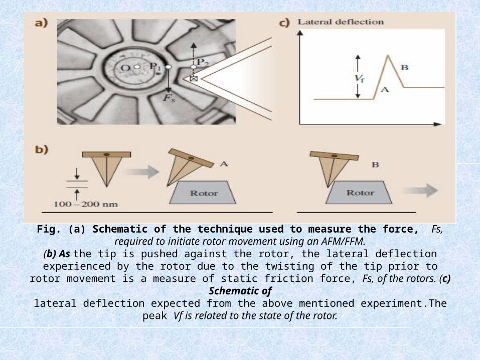
Fig. (a) Schematic of the technique used to measure the force, Fs, required to initiate rotor movement using an AFM/FFM.
(b) As the tip is pushed against the rotor, the lateral deflection experienced by the rotor due to the twisting of the tip prior to rotor movement is a measure of static friction force, Fs, of the
rotors. (c) Schematic oflateral deflection expected from the above mentioned experiment.The peak Vf is related to the
state of the rotor.
• Now consider an AFM tip moving against a rotor arm in a direction perpendicular to the long axis of the cantilever beam (the rotor arm eest to the tip is parallel to the long axis of the cantilever beam), as shown in Fig.a. When the tip encounters the rotor at point P2, the tip will twist, generating a lateral force between the tip and the rotor(event A in Fig. b). This reaction force will generate a torque about the center of the motor.
• Since the tip is trying to move farther in the direction shown, the tip will continueto twist to a maximum value at which the lateral force between the tip and the rotor becomes high enough such that the resultant torque Tf about the center of the motor equals the static friction torque Ts.
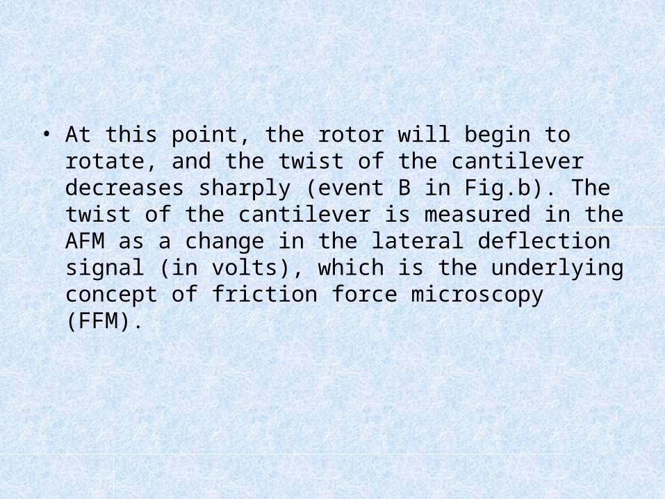
• At this point, the rotor will begin to rotate, and the twist of the cantilever decreases sharply (event B in Fig.b). The twist of the cantilever is measured in the AFM as a change in the lateral deflection signal (in volts), which is the underlying concept of friction force microscopy (FFM).
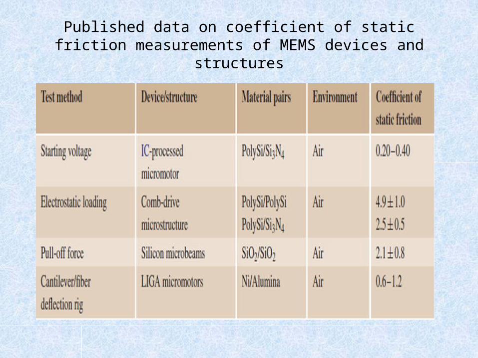
Published data on coefficient of static friction measurements of MEMS devices and structures
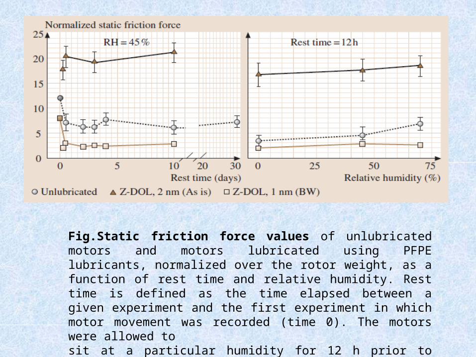
Fig.Static friction force values of unlubricated motors and motors lubricated using PFPE lubricants, normalized over the rotor weight, as a function of rest time and relative humidity. Rest time is defined as the time elapsed between a given experiment and the first experiment in which motor movement was recorded (time 0). The motors were allowed tosit at a particular humidity for 12 h prior to measurements
• It can be seen that for the unlubricated motor and the motor lubricated with a bonded layer of Z-DOL(BW), the static friction force is highest for the first experiment and then drops to an almost constant level.
• In the case of the motor with an as-is mobile layer of Z-DOL, the values remain very high up to 10 days after lubrication. In all cases, there is negligible difference in the static friction force at 0% and 45% RH. At 70% RH, the unlubricated motor exhibits a substantial increase in the static friction force, while the motor with bonded ZDOL shows no increase in static friction force due to the
hydrophobicity of the lubricant layer.
Conclusion
• A solid-like hydrophobic lubricant layer (such as bonded Z-DOL) results in favorable friction
characteristics of the motor.• The hydrophobic nature of the lubricant inhibits
meniscus formation between the contact surfaces and maintains low friction even at high humidity.
• This suggests that solid-like hydrophobic lubricants are ideal for lubrication of MEMS,while mobile lubricants result in increased values of static friction force.

THANK YOU