static and dynamic stability performance measurements of
TRANSCRIPT

Static and Dynamic Stability Performance Measurements of the HLPR Chair/Forklift
Joshua Johnson Florida Gulf Coast University
Ft. Myers, FL
Roger Bostelman National Institute of Standards and Technology
Gaithersburg, MD 20899
January 15, 2010
ABSTRACT The Home Lift, Position and Rehabilitation (HLPR) Chair, developed at the National Institute of Standards and Technology (NIST), has unique capabilities and a unique shape as compared to conventional wheelchairs and powered chairs. The evaluation of its static and dynamic stability is necessary to ensure rider safety. Recently, the HLPR Chair was converted into an autonomous forklift for the manufacturing industry. The HLPR forklift includes articulated forks that replace the chair from the original HLPR Chair design. Both the HLPR Chair and HLPR forklift prototypes can carry approximately 114 kg (250 lb) beneath an upper rotation joint (i.e., rotates the seat or the forks). HLPR stability was evaluated based on the American National Standard (ANSI) and the International Organization of Standardization (ISO) wheelchair and forklift standards. Also, new test methods were created and tested that are currently not provided in these standards because of HLPR’s unique lift and rotation capabilities. The following report details the standard and new test methods and test results.
2

TABLE OF CONTENTS
1. INTRODUCTION.......................................................................................................... 4 2. STATIC STABILITY .................................................................................................... 6
2.1 Background ........................................................................................................... 6 2.2 Experimental setup ................................................................................................ 6 2.3 Methodology ......................................................................................................... 7
2.3.1 Testing forward stability ............................................................................. 7 2.3.2 Testing rearward stability ........................................................................... 8 2.3.3 Testing sideways stability ........................................................................... 9
2.4 Results ................................................................................................................. 11 3. DYNAMIC STABILITY ............................................................................................. 13
3.1 Background ......................................................................................................... 13 3.2 Experimental Setup ............................................................................................. 13 3.3 Methodology ....................................................................................................... 14
3.3.1 Rearward Dynamic Stability..................................................................... 14 3.3.2 Forward Dynamic Stability....................................................................... 15 3.3.3 Lateral Dynamic Stability ......................................................................... 15 3.3.4 Dynamic Stability while Traversing a Step .............................................. 15
3.4 Dynamic Test Results.......................................................................................... 16 4. DISCUSSION .............................................................................................................. 17 5. SUGGESTED CHANGES TO CURRENT STANDARDS........................................ 18 6. ACKNOWLEDGEMENTS ......................................................................................... 21 7. REFERENCES............................................................................................................. 22 8. APPENDIX: HLPR CHAIR TEST ORIENTATIONS................................................ 23
8.1 Forward Static Stability....................................................................................... 23 8.2 Rearward Static Stability..................................................................................... 27 8.3 Lateral Static Stability ......................................................................................... 28
LIST OF TABLES
Table 1. Configurations for Forward Stability ................................................................. 7 Table 2. Configurations for Rearward Stability ................................................................ 9 Table 3. Configurations for Sideways Stability .............................................................. 10 Table 4. Static Forward Stability Test Results ................................................................ 11 Table 5. Static Rearward Stability Test Results .............................................................. 12 Table 6. Static Lateral Stability Test Results .................................................................. 12 Table 7. ANSI/RESNA Scoring System for Dynamic Stability ..................................... 15 Table 8. Dynamic Stability Test Results ......................................................................... 16 Table 9. Dynamic Stability while Traversing a Step Test Results ................................. 17 Table 10. Mean Static Tipping Angles ........................................................................... 17
3

1. INTRODUCTION A novel Home Lift, Position, and Rehabilitation (HLPR) Chair has been designed and built at the National Institute of Standards and Technology (NIST) [1, 2, 3] to provide independent patient mobility for indoor tasks, such as moving to and placing a person on a toilet or bed, and lift assistance for tasks, such as accessing kitchen or other tall shelves. These functionalities are currently out of reach of most wheelchair users. One of the design motivations of the HLPR Chair is to reduce back injury, typically, an important issue in the care of this group. The HLPR Chair was also tested as an autonomous mobility device to assist cognition by route and trajectory planning. To date, two HLPR Chair (1 and 2) prototypes have been built. HLPR Chair 1, used in these stability experiments, was also developed into an autonomous wheelchair. HLPR Chair 2 was modified from the first design to develop a more cost effective manufacturing design, a more ergonomic and standard seat design and a larger seat rotation system for higher side-to-side stability, as well as other smaller modifications. The unique shape (see Fig. 1) and capabilities of the HLPR as compared to typical wheel- and powered chairs requires examination of its stability. Existing standards do not adequately cover this design. Unique characteristics of the HLPR chair that are not included in current standards are: 1 m lift, seat rotation, and two casters with single wheel drive-and-steer wheel design with stabilizers.
Figure 1: Typical powered chair (left) [courtesy Jazzy1] and the HLPR Chair 1 prototype
(right three photos). HLPR Chair is shown in the mobility (center photos) and the lift (left-most) configurations. Note the unique shape of HLPR Chair as compared to typical
powered chairs.
1 Certain commercial equipment, instruments, or materials are identified in this report in order to specify the experimental procedure adequately. Such identification is not intended to imply recommendation or endorsement by the National Institute of Standards and Technology, nor is it intended to imply that the materials or equipment identified are necessarily the best available for the purpose.
4

As a load-carrying device, the frame and wheelbase closely resemble a walk-behind forklift. For this reason, ANSI/RESNA and ISO standards for wheelchairs and forklifts were adapted to assess the stability of the HLPR under both static and dynamic conditions. The standards referenced for these stability tests were:
International Standard IS0 7176-1:1999 (E) Wheelchairs – Part 1: Determination of static stability [4]
International Standard IS0 7176-2: 2001 (E) Wheelchairs – Part 2: Determination of dynamic stability of electric wheelchairs [5]
International Standard IS0 7176-7:1998 (E) Wheelchairs – Part 7: Measurement of seating and wheel dimensions [6]
International Standard IS0 7176-10:1998 (E) Wheelchairs – Part 10: Determination of obstacle-climbing ability of electric wheelchairs [7]
International Standard IS0 7176-11:1992 (E) Wheelchairs – Part 10: Test dummies, first edition 1992-05-01. [8]
International Standard IS0 7176-22:2000 (E) Wheelchairs – Part 22: Set-up Procedures, first edition 2000-05-15 [9]
International Standard IS0 1074: 1991 (E) Counterbalanced fork-lift trucks – Stability tests [10]
Australian Standard AS 3581-1988, Mechanical Aids for Patient Lifting and Moving – Safety Requirements [11]
American National Standard ANSI for Wheelchairs – Volume 1: Requirements and Test Methods for Wheelchairs (Including Scooters), [12]
American National Standard ANSI for Wheelchairs – Volume 2: Additional Requirements for Wheelchairs (Including Scooters) with Electrical Systems, [13]
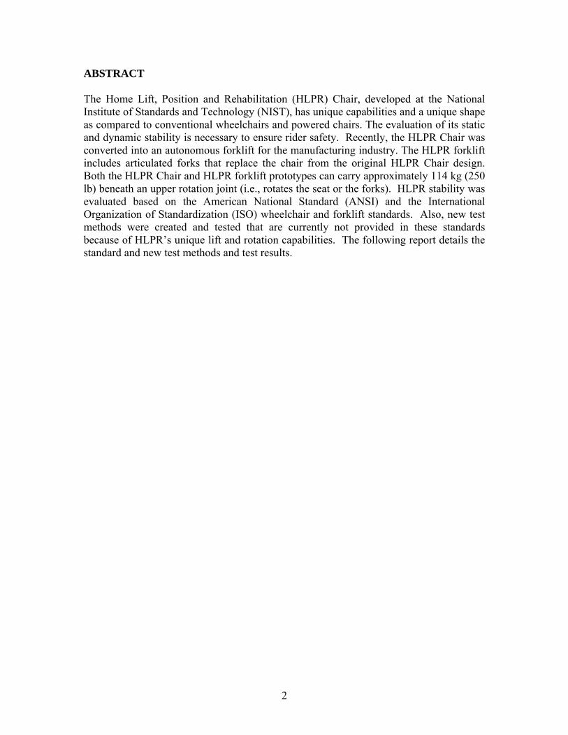
Non-existent stability test methods were developed with consideration of HLPRs transition from an intelligent powered and lift wheelchair to a load-carrying and lift device for the manufacturing industry. Figure 2 shows HLPR in the articulated forklift configuration. By utilizing HLPR rotation joint with an articulated forklift, a user can manually load and secure the load by placing it onto the lower frame. A user can then either manually push or autonomously send the load to the target location. In the case of existing and similar standards between wheelchairs and forklifts, the most rigorous test was adapted. The purposes of the stability tests were to determine the maximum safe load capabilities, the maximum safe angle of operation, and the braking capabilities of the HLPR. The stability tests were performed between May and August 2008. This paper will describe the testing procedures used for static and dynamic stability testing of the HLPR, as well as standard and new suggested standard methods of stability testing for this unique mobile/lift wheelchair and forklift. The paper begins with static stability background, methodology, tests and results followed by dynamic stability background, methodology, tests and results. Following are a discussion section which summarizes the results, an acknowledgement section and a references section. An appendix section then follows which includes several photos of the experimental setup.
5
Rear stabilizer casters
Figure 2. HLPR 1 prototype transitioned into an articulated forklift and shown in the (left) loading and (right) loaded-mobility configurations.
2. STATIC STABILITY 2.1 Background International Standard IS0 7176-1 for Wheelchairs deals with the determination of static stability. This standard parallels Section 1 of the ANSI/RESNA Wheelchair standards. The intention of the tests is to determine basic information about the angle of tip of the HLPR in its most and least stable configuration. The HLPR was tested in three orientations: uphill, downhill, and sideways. Depending on the direction of tip, the HLPR can tip about the front wheel axle or about any of the three wheel contact points with the ground. The footprint of the vehicle has a large bearing on stability. When the HLPR is on a level surface, the two front wheels and the singular rear wheel touch the ground. If imaginary horizontal lines connect the three wheels in a triangle, the result would be the footprint. As long as the center-of-gravity (COG) of the HLPR/load remains within the footprint, the HLPR is statically stable. The HLPR has been modified with rear stabilizers as a safety feature. If tip occurs, particularly when the device is orientated sideways (see Fig. 2), the stabilizers provide a very small, adjustable HLPR tip angle (e.g., less than 5°). The HLPR design enables a rider or load to be positioned at a height above that of a traditional wheelchair. The COG of the HLPR/load system is greatly affected by the height. The HLPR seat can be raised or lowered so that a person can transfer to and from a chair, toilet, or bed. Also, the seat frame rotation that enables patient transfer shifts the COG of the HLPR/load system and affects static stability. Due to the flexibility of the HLPR these configurations must be tested individually: load at lowest height, load raised 1 m to great height, seat frame rotated to 4 different positions. 2.2 Experimental setup A tilting platform was designed and built to support the 113 kg HLPR Chair and its 113 kg payload. The 2.44 m x 11.22 m (8 ft x 4 ft) platform included a hand crank winch to lift one end of the platform to various angles from 0º through 25º as shown in Figure 3.
6
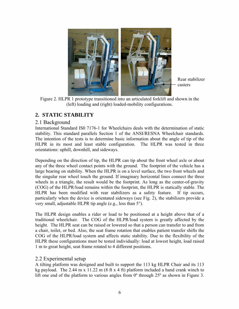
The platform friction was tested using the standard method of a weight placed on a piece of rubber while tilting the platform prior to beginning actual HLPR tests. Angles were measured using a digital angle measurement device with 25º maximum angle.
Figure 3. Stability test platform and safety devices.
hand crank winch
safety strap
platform
tip restraint bar
slip prevention bar
During the test, a piece of paper, attached to the platform edge by a rubber band, was placed beneath the most raised HLPR wheel(s) to alert the platform winch operator as to the exact moment the HLPR wheels tip off the platform. At this point, the platform angle is measured and recorded. Figure 8 in the Appendix section shows this test setup. 2.3 Methodology
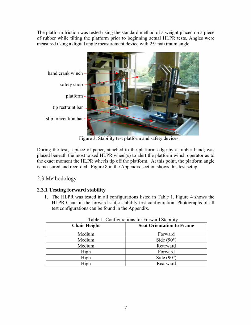
2.3.1 Testing forward stability 1. The HLPR was tested in all configurations listed in Table 1. Figure 4 shows the
HLPR Chair in the forward static stability test configuration. Photographs of all test configurations can be found in the Appendix.
Table 1. Configurations for Forward Stability Chair Height Seat Orientation to Frame
Medium Forward Medium Side (90°) Medium Rearward
High Forward High Side (90°) High Rearward
7

sandbags
Figure 4. The HLPR being tested for forward static stability
2. Five sandbags, totaling105 kg, were strapped onto the HLPR seat with weight distributed similar to a human body sitting in the seat.
3. The HLPR was placed facing downhill with the front wheels obstructed by a crossbar to prevent it from rolling or sliding. A piece of high-gloss paper (0.08 mm thick) was placed under the rear wheel and affixed to the platform perpendicularly with a rubber band. The tipping angle was reached when the piece of paper slid from beneath the uphill rear wheel.
4. The sandbags were adjusted to be in similar weight distribution for each test, step 3 was repeated, and tipping angle was recorded for each combination.
2.3.2 Testing rearward stability 1. The HLPR was tested in all configurations listed in Table 2. Figure 5 shows the
HLPR Chair in the rearward static stability test configuration. Photographs of all the various configurations can be found in the Appendix.
2. Five sandbags, totaling105 kg, were placed in the HLPR seat with weight distributed similar to a human body sitting in the seat.
3. The HLPR was placed facing uphill with the rear wheel obstructed by a crossbar to prevent it from rolling or sliding. A piece of high-gloss paper (0.08 mm thick) was placed under the front wheel and affixed to the platform perpendicularly with a rubber band. The tipping angle was reached when the piece of paper was slid from under the uphill front wheel.
8

4. The sandbags were adjusted to be in similar weight distribution for each test, step 3 was repeated, and tipping angle was recorded for each configuration.
Table 2. Configurations for Rearward Stability
Chair Height Seat Orientation to Frame
Medium Forward Medium Side (90°) Medium Rearward
High Forward High Side (90°) High Rearward
Figure 5. The HLPR being tested for rearward static stability
2.3.3 Testing sideways stability The HLPR was tested in all configurations listed in Table 3. Figure 6 shows the HLPR Chair in the sideways static stability test configuration. Photographs of all configurations can be found in the Appendix.
9

Table 3. Configurations for Sideways Stability Chair Height Seat Orientation to Frame
Medium Forward Medium Side (90°) Medium Rearward
High Forward High Side (90°) High Rearward
1. Five sandbags, totaling105 kg, were placed in the HLPR seat with weight
distributed similar to a human body sitting in the seat. 2. The HLPR was placed sideways with the most uphill wheel (a front caster)
obstructed by a crossbar to prevent it from rolling or sliding. A piece of high-gloss paper (0.08 mm thick) was placed under the most uphill wheel and affixed to the platform perpendicularly with a rubber band. The tipping angle was reached when the piece of paper was slid from under the uphill wheel.
3. The sandbags were adjusted to be in similar weight distribution for each test, step 3 was repeated, and tipping angle was recorded for each combination.
Figure 6. The HLPR being tested for sideways static stability
10

11
2.4 Results Static stability tests were performed a total of five times per a given configuration. In Tables 4-6, μ is the mean value of the five tests and σ is standard deviation of those values. Data listed in the Platform and HLPR columns are slightly different from each other suggesting that deformation of the tires and/or frame may have occurred. This is an important point as the flexibility of the system being measured may alter the expected COG. For these experiments, maximum tip angle was set to the digital measurement device maximum of 25° since this angle is well beyond what the test operators expect HLPR to encounter in normal use.
Table 4. Static Forward Stability Test Results Medium Chair Height
(1.28m) High Chair Height
(1.78m) Test #, μ, σ Platform HLPR Platform HLPR
1 18.5° 19.5° 13.7° 14.4° 2 15.8°1 16.3°1 12.6° 13.8° 3 18.6° 19.3° 13.0° 13.7° 4 18.5° 19.4° 12.9° 13.0° 5 17.8° 18.6° 12.4° 13.0° μ 18.4° 19.2° 12.9° 13.6°
For
war
d
σ 0.32 0.35 0.44 0.53 1 18.3° 19.1° 12.9° 13.7° 2 17.5° 18.1° 12.7° 13.4° 3 18.3° 19.3° 12.8° 13.6° 4 17.4° 18.1° 12.7° 13.4° 5 17.5° 18.3° 12.3° 13.1° μ 17.8° 18.6° 12.7° 13.4° S
ide
(90°
)
σ 0.41 0.51 0.20 0.21 1 17.4° 18.2° 11.8° 12.5° 2 16.8° 17.5° 12.1° 12.8° 3 17.1° 17.7° 12.1° 12.6° 4 17.2° 18.0° 12.1° 13.0° 5 18.0° 19.0° 12.7° 13.4° μ 17.3° 18.1° 12.2° 12.4°
Sea
t Ori
enta
tion
Rea
r
σ 0.40 0.52 0.29 0.32
[1] The values for seat orientation forward test #2 were not included in the mean or standard deviation, as they may have been impacted by the orientation of the safety catch device.
Table 5 shows every tip angle to be >25° and is therefore, the most stable of the three static configurations tested. The researchers concluded that it was best to show the actual data tabulated for each test in a format consistent with Tables 4 and 6.

Table 5. Static Rearward Stability Test Results
Medium Chair Height (1.28m)
High Chair Height (1.78m)
Test #, μ, σ Platform HLPR Platform HLPR 1 >25° >25° >25° >25° 2 >25° >25° >25° >25° 3 >25° >25° >25° >25° 4 >25° >25° >25° >25° 5 >25° >25° >25° >25° F
orw
ard
μ >25° >25° >25° >25° 1 >25° >25° >25° >25° 2 >25° >25° >25° >25° 3 >25° >25° >25° >25° 4 >25° >25° >25° >25° 5 >25° >25° >25° >25° S
ide
(90°
)
μ >25° >25° >25° >25° 1 >25° >25° >25° >25° 2 >25° >25° >25° >25° 3 >25° >25° >25° >25° 4 >25° >25° >25° >25° 5 >25° >25° >25° >25°
Sea
t Ori
enta
tion
Rea
r
μ >25° >25° >25° >25°
Table 6. Static Lateral Stability Test Results Medium (1.28m) High (1.78m)
Test #, μ, σ Platform HLPR Platform HLPR 1 7.9 9.8 5.5 6.9 2 8.2 10.1 5.0 6.5 3 7.8 9.3 4.4 6.0 4 7.9 9.5 4.5 6.3 5 8.3 10.1 5.0 6.7 μ 8.0 9.8 4.9 6.5
For
war
d
σ 0.19 0.32 0.40 0.31 1 8.2 10.1 5.4 7.2 2 7.9 9.5 4.8 6.3 3 7.9 9.9 4.5 6.1 4 8.2 10.1 4.3 5.9 5 8.1 10.4 4.8 6.4 μ 8.1. 10.0 4.8 6.4 Sid
e (9
0°)
σ 0.14 0.30 0.37 0.44 1 8.4 10.4 5.0 7.0 2 8.7 10.5 5.2 7.2 3 8.7 10.5 5.1 7.0 4 8.7 10.6 5.0 7.0 5 9.1 10.8 5.4 7.3 μ 8.7 10.6 5.1 7.1
Sea
t Ori
enta
tion
Rea
r
σ 0.22 0.14 0.15 0.13
12

3. DYNAMIC STABILITY
3.1 Background International Standard IS0 7176-2 for Wheelchairs details the determination of dynamic stability of electric wheelchairs. This standard parallels Volume 2 of the ANSI/RESNA Wheelchair standards. This test is intended to determine the stability of a powered wheelchair when it is driven up and down inclined planes of varying degrees. The wheelchair is driven at maximum speed on slopes of 0º, 3º, 6º, and 10º. Forward downhill braking, backward downhill braking, and forward uphill braking are performed on the slopes. The stability of the wheelchair during these maneuvers is then rated. 3.2 Experimental Setup A different platform was designed and built to support the HLPR Chair dynamic stability measurements. This platform measured approximately 2.4 m wide x 3.7 m long (8 ft x 12 ft) and was built as a modular platform to disassemble into three approximately 1.2 m x 2.4 m (4 ft x 8 ft) sections while built to ANSI specifications to allow sufficient wheelchair travel. The platform was capable of tilting, using hand crank winches, to 0°, 3°, 6°, and 9° angles. As shown in Figure 7, a passenger is being used as the payload (approximately 93 kg) for forward tests. Not shown are tests that used sand bags as payload for all rear and lateral tests. In the figure, the passenger is ready to drive forward at full speed and turn left. Extreme caution was exercised to prevent passenger or HLPR Chair harm by using straps to facility hard points (fixtures to walls and superstructures) and a second test operator/observer. HLPR dynamic stability test start positions were chosen to ensure that the HLPR would not traverse off the platform. HLPR was estimated by an observer to accelerate on a level surface from a stopped position to a maximum 0.7 m/s in approximately 1 m when fully loaded with approximately 93 kg. The list of tests performed were as follows:
1. Rearward dynamic stability on ramp 2. Forward dynamic stability on ramp 3. Lateral dynamic stability on ramp 4. Lateral dynamic stability while turning in circles 5. Lateral dynamic stability while turning suddenly 6. Dynamic stability while traversing a step
HLPR tip was measured during each test by an observer. Each test from 1 through 5 was performed with the HLPR at a slope of 0°, 3°, 6°, and 10° with results shown in Table 8. For test 6, Dynamic stability while traversing a step, only a slope angle of 10° was used as suggested by ISO 7176-2 and results of this test are shown in Table 9.
13

operator on HLPR Chair ready to test platform center platform support leg
Figure 7. HLPR chair dynamic stability test setup. 3.3 Methodology
3.3.1 Rearward Dynamic Stability 1. The HLPR chair height was set at the medium height (1.28m), as marked on the
HLPR. 2. Six sandbags totaling 105 kg were strapped into the HLPR seat. 3. The performance of the HLPR was rated according to the scale shown in Table 7. 4. The HLPR was then placed on a level test plane. 5. From a stationary start, the controls were operated to give maximum acceleration
in the forward direction. The response was scored according to Table 7. 6. Step 5 was then repeated on slopes of 3°, 6°, and 10° with the HLPR facing
uphill. 7. The HLPR was then run at maximum speed on the level test plane. 8. Braking was initiated by releasing the joystick and the dynamic response of the
HLPR was scored according to Table 7. 9. Steps 7-8 were repeated, but braking was initiated by putting the joystick in
reverse. 10. Steps 7-8 were repeated again, but braking was initiated by turning while pressing
the rear emergency stop pushbutton (located with the caregiver controls). 11. Steps 7-10 were repeated on slopes of 3°, 6°, and 10° with the HLPR traveling
forward on the uphill slope. 12. Steps 7-11 were then repeated with the HLPR traveling at maximum speed
backwards down the slope.
14

Table 7. ANSI r Dynamic Stability
O Score /RESNA/ISO Scoring System fo
bserved Dynamic Response
No tip At least one lifting wheel remains on the test plane. 3
Transient tip o or not any anti-tip devices
2 All lifting wheels2 lose contact, then drop back ontthe test plane, whether contact the test plane.
Stuck on anti-tip device , and the HLPR remains stuck
1 All lifting wheels lift off, the HLPR anti-tip device contacts the test plane on the anti-tip device
Full tip re from a
restraining device or testing personnel.
0 The HLPR tips completely over (90° or moits original orientation) unless caught by
[2] Lifting wheels are the wheel(s) that lose contact with the test plane which, for these experiments, is the sloped platform.
LPR chair. sting.
dynamic response of the
were repeated, but braking was initiated by putting the joystick in
plane. 9. The response of the HLPR was scored and recorded according to Table 7.
PR chair.
PR was turned to the left with maximum acceleration until it was facing
orded according to Table 7. 7. Steps 4-6 were repeated on 6° and 10° slopes
transitioning to/from a 25 mm horizontal step. HLPR was controlled at a relatively slow
3.3.2 Forward Dynamic Stability 1. The HLPR was set with the seat orientation facing forward. 2. The seat height was set to medium (1.28m) as marked on the H3. A human driver of a 97 kg mass was used to perform te4. The HLPR was run at maximum speed down 3° slope. 5. Braking was initiated by releasing the joystick and the
HLPR was scored and recorded according to Table 7. 6. Steps 4-5
reverse 7. Steps 4-5 were repeated again, but braking was initiated by activating the
emergency stop located with the caregiver controls at the rear of the HLPR. 8. The HLPR is run at maximum speed down a 3° slope onto a horizontal test
3.3.3 Lateral Dynamic Stability 1. The HLPR was set with the seat orientation facing forward. 2. The seat height was set to medium (1.28 m) as marked on the HL3. Six sandbags at a total of 105 kg were placed in the HLPR seat. 4. The HLPR was positioned facing downhill on a 3° test plane 5. The HL
uphill. 6. The response of the HLPR was scored and rec
3.3.4 Dynamic Stability while Traversing a Step Similar to section 3.3.2 Forward Dynamic Stability, forward tests were run for the Dynamic Stability while Traversing a Step test with a ramp slope height set at 10°
15

HLPR speed until it transitioned to/from the slope to/from the step. Each test was repeated three times and no other step heights were tested. Results are shown in Table 9. 3.4 Dynamic Test Results Table 8 shows the Dynamic Stability Test Results for the HLPR Chair when following ISO 7176-2 Wheelchairs – Part 2: Determination of dynamic stability of electric wheelchairs, Annex B. Each column in Table 8 is described as follows: Test: lists the type of test and how it was performed. For example, the Rearward Dynamic Stability test was performed by HLPR starting forward motion, by stopping after traveling forwards and by braking when traveling backwards. Method of Retardation: is the method used to cause HLPR to decelerate from maximum speed to a complete stop.
Release: the operator lets go of the joystick used to command HLPR acceleration. Power off: the operator turns off power to HLPR Applying reverse: the operator rapidly moves the joystick from full commanded HLPR acceleration in the direction of travel to full commanded HLPR acceleration in the exact opposite direction
Stability Score at various ramp angles: at each ramp angle HLPR was tested, an associated score of 0, 1, 2, or 3 as described in Table 7 was listed. Comments: comments for each test were listed during the test by the researcher. Slipping was noted when HLPR wheels slid on the platform.
Table 8. Dynamic Stability Test Results Stability Score
at various ramp angles Test Method of
Retardation 0° 3° 6° 10°
Comments
Rearward Dynamic Stability Starting Forward 3 3 3 3 Slipping occurs at 3°
R Release 3 3 3 3 Slipping occurs at 3° P Power off 3 3 3 3 Slipping occurs at 3°
Stopping after traveling forward
A Applying reverse 3 3 3 3 Slipping occurs at 3° R Release 3 3 3 3 Slipping occurs at 3° P Power off 3 3 3 3 Slipping occurs at 3°
Braking when traveling backward
A Applying reverse 3 3 3 3 Slipping occurs at 3° Forward Dynamic Stability
R Release 3 3 3 3 Slipping occurs at 3° P Power off 3 3 3 3 Slipping occurs at 3°
Braking when traveling forward
A Applying reverse 3 3 3 3 Slipping occurs at 3° Traveling forward down a slope onto a horizontal surface
N/A N/A 3 3 0
2
Complete tip Transient tip
Dynamic Stability in Lateral Directions Turning on a slope N/A 3 2 2 0 Transient tip on
highest positioned front wheel
Turning suddenly at maximum speed
N/A 3 N/A N/A N/A
16

HLPR Chair is not designed to travel up and down steep ramps and transition steps from these ramps. When following ISO 7176-2 Wheelchairs – Part 2: Determination of dynamic stability of electric wheelchairs, Annex B, the steep 10° ramp angle to/from a step caused transient tipping or complete tipping. The test was determined unsafe by the researchers and halted. Therefore, Table 9 shows the Dynamic Stability while Traversing a Step Test Results for the HLPR Chair when HLPR traveled from a horizontal surface to/from a step transition. This test better fit the HLPR design as it may encounter doorway thresholds. Each column in Table 9 is described as follows: Test: lists the type of test and how it was performed. Stability Score: 25 mm step height: at a 25 mm step height that HLPR traversed, an associated score of 0, 1, 2, or 3 as described in Table 7 was listed. The researchers only tested one step height three times each to understand the test methodology although ISO 7176-2 suggests testing at several step heights.
Table 9. Dynamic Stability while Traversing a Step Test Results using a horizontal test surface instead of a 10° ramp as suggested by the standard.
Stability Score 25 mm step height
Test
1 2 3
Comments
Rearward Dynamic Stability Travelling forward up a step transition from a standing start
3 3 3 Horizontal test surface up a step
Travelling backward down a step transition from a standing start
3 3 3 Horizontal test surface down a step
Forward Dynamic Stability Travelling forward up a step transition at maximum speed
3 3 3 Horizontal test surface down a step
Traveling forward down a step transition from a standing start
3 3 3 Horizontal test surface down a step
Dynamic Stability in Lateral Direction One side of HLPR drops down a step transition 3 3 3 Horizontal test surface
down a step
4. DISCUSSION While undergoing static stability testing in the forward and rear directions, the HLPR demonstrated favorable results as shown by the mean tipping angles in Table 10. The tipping angle in the rear direction exceeded 25° for both the medium and high seat heights. Conversely, the tipping angle recorded was very low for static testing in the lateral direction. Of particular interest is the mean tip angles when the HLPR is tested laterally with the seat in the high position; the tip angle for all seat orientations is under 6°. This is due to the narrow width of the HLPR. At the high configuration the COG easily leaves the footprint of the device. During dynamic stability testing, the HLPR frequently slipped before tipping occurred. As to be expected based on static performance, the HLPR experienced transient tipping or complete tipping when undergoing dynamic lateral stability testing. The Dynamic
17

Stability while Traversing a Step tests and results shown in Table 9 were slightly different tests from those suggested in standards where HLPR transitioned from a horizontal surface to a step. For these tests, results were excellent. However, HLPR traveling forward down an incline set at 10° onto a horizontal surface, as suggested by the standards, caused either transient or complete tipping.
Table 10. Mean Static Tipping Angles HLPR Height HLPR Frame
Orientation Seat
Orientation Medium (1.28m) High (1.78m) Forward 18.4° 12.9°
Side 17.5° 12.7° Forward
Rear 17.3° 12.2° Forward >25° >25°
Side >25° >25° Rear
Rear >25° >25° Forward 8.0° 4.9°
Side 8.1° 4.8° Lateral
Rear 8.7° 5.1° Suggested design changes to prevent HLPR Chair slipping and tipping might be to lighten the weight of the upper HLPR Chair frame and/or add weight to its bottom frame. HLPR Chair weighs approximately 113 kg without payload and totals 226 kg with a 113 kg rider or test dummy. To prevent tipping, a wider base or caster design is suggested which can also be changeable for narrow doorway entrance as needed.
5. SUGGESTED CHANGES TO CURRENT STANDARDS The modifications listed below would enhance current standards to support devices built now and in the future that have similar characteristics as the HLPR Chair. 1. Seat Rotation: a. The ISO 7176-1 Wheelchairs – Part 1 Determination of Static Stability standard states:
9.2 Wheels unlocked and the wheelchair in the least stable configuration 9.2.1 Set adjustable parts of the wheelchair in the least stable configuration for forward stability. Table 1(in the standard) illustrates the effect of typical adjustments.
The standard refers to a forward stability table where there is currently no listing for seat rotation as HLPR Chair can provide. Therefore, we suggest the following additions to ISO 7176-1 Table 1-Forward Stability:
Adjustable wheelchair component
Least stable
Most stable
Seat position, rotation Reverse Forward
The reason for the suggested addition to the ISO 7176-1 standard is because when tilted forward, the loaded seat can cause the HLPR center-of-gravity (CG) to be forward of the
18

casters and cause increased tip potential dependent upon the angle and HLPR Chair design and construction. b. Furthermore, a similar description is shown in ISO 7176-1 standard section 10, Table 2-Rearward Stability and in section 12, Table 3-Sideways Stability. We therefore suggest the additions as follows: Addition to ISO 7176-1 standard Table 2-Rearward Stability
Adjustable wheelchair component
Least stable
Most stable
Seat position, rotation Forward Reverse
Addition to Table 3-Sideways Stability
Adjustable wheelchair component
Least stable
Most stable
Seat position, rotation Down-slope Up-slope
c. Seat rotation is also not listed in ISO 7176 – 22 Wheelchairs – Set-up procedures and specifically within section 6.3.4 which discusses the Seat and backrest set-up for testing. Also, Annex A should include an entry in the “record of measurements and settings for set-up procedures in accordance with ISO 7176-22” table for Seat rotation. 2. Test apparatus and method 1 ISO 7176 Part 1, section 3.2 tipping angle states that the tipping angle occurs when the uphill-wheels forces on the platform become zero. Below this statement in the standard is a note stating there are a number of methods to determine when this occurs. One method occurs when someone is able to pull a piece of paper from beneath the uphill wheel and the test plane. This is difficult for a single test operator using a manual test plane lift mechanism such as a hand winch or hydraulic piston. The operator may be required to stop platform tilting to do the paper-pull test. Similarly, if the operator or other test helper is available to do the paper-pull test, it places them at some risk near the test. Alternatively, a method used to test the HLPR Chair was a simple rubber band, (see Appendix Figure 9) attached between the paper and the test plane so that when tip occurs, the paper springs out by itself from beneath the wheel. At that moment, the test is stopped and the tilt angle can be recorded. This allows continuous platform tilting with no safety risk to the test operators. Similarly, remote reading of electronic force-sensing instrumentation as pointed out in the standard could be used. 3. Test apparatus and method 2 ANSI/RESNA and ISO wheelchair standards show a horizontal restraint bar to support the wheelchair and payload (rider or test dummy) from tipping too far during static stability tests. The horizontal restraint bar is very useful but provides only one axis of restraint and at only one level which requires rigid adjustment for tall patient mobility devices. The single axis restraint may be all this is currently necessary for existing devices. However, this may not be sufficient for future lift-wheelchairs with HLPR Chair
19

capabilities. Instead, NIST researchers testing HLPR stability used an adjustable safety harness (rope or strap) (see Figure 8) attached between a facility hard-point and the top of the HLPR to prevent it from tipping too far. The overhead harness is very useful in that it provides a safe, flexible, yet loose restraint attached to the HLPR Chair top to prevent collapse from any angle or height being tested. Also, a sliding crossbar with a flexible link was attached between the platform and the base of HLPR that prevented the HLPR from raising more than 50 mm off of the test surface. ANSI/RESNA WC/Vol. 1-1998 and ISO 7176-1 shows a roll restraint fixed to the platform only at the wheel and downhill point of the device being tested and/or a flexible restraint both combined with the tip restraint horizontal bar. We used both the upper harness restraint and a sliding crossbar for maximum safety during tests because there were no facility hard-points beside the test platform that supported the use of a heavy duty horizontal restraint bar. Use of an upper harness and sliding crossbar improved the test safety especially for tall devices like HLPR Chair. 4. Test apparatus and method 3 HLPR Chair not only provides patient mobility and transfer capabilities, but also provides for rehabilitation. Current off-the-shelf (OTS) stand/mobile powered chair technology (see Figure 8 (left)) can typically raise a rider to a standing position. However, this technology does not allow the rider to walk nor stand on the floor nor to move or exercise their legs in normal walking fashion. As shown, the OTS and HLPR Chair supports the patient as they command the powered chair to move.
Figure 8. (left) Off-the-shelf standing type powered chair (courtesy Permobil), (center) HLPR Chair 1 in the patient rehabilitation configuration. The prototype is supporting a
patient while they or a caregiver (behind HLPR) commands HLPR to move. (right) HLPR Chair 2 supports a patient with a sling ready for transfer to a seat, toilet or bed.
HLPR Chair provides for mobility and also provides a rehabilitation and exercise configuration, as shown in Figure 8 (center), allowing the patient to stand directly on the floor while supported by HLPR.
20

The patient or a caregiver can also command the HLPR to drive in this configuration allowing the patient to exercise their legs or for leg rehabilitation. The figure shows the two devices, OTS powered chair (left) and HLPR Chair 1 (center) and 2 (right), supporting the patient by arm-rests in the OTS powered chair and with crutches-type underarm torso lifts or a sling on the HLPR Chair. These configurations also need to be considered in the ANSI/RESNA and ISO stability standards. Standing (and sitting) slings can be attached to these mobile/lift devices adding further complexity to stability measurements. For example, Figure 8 (right) shows a patient ready to be transferred to another seat where the HLPR Chair seat has been rotated behind the patient and the patient is suspended by a sitting sling. Similarly, a standing (parachute-type) harness, which can prevent under arm stress, could be attached to the HLPR Chair to allow patients to walk while HLPR Chair moves. These relatively new configuration types and slings could be added to stability test method standards for mobile patient transport devices. Some industry standards, among others not listed here, that may have text to add to current wheelchair standards are: ASME / ANSI Standards. B30.2. Overhead Cranes ANSI/ASME B30.9 – 1984 Slings ASME B30.21 – 1982 Manual Lever Operated Hoists ANSI/ITSDF B56.10 - 2006, Safety Standard for Manually Propelled High Lift
Industrial Trucks Occupational Safety and Health Administration (OSHA) 1910.67 or ANSI A92.2-
1969 Vehicle Mounted Elevating and Rotating Work Platforms. 5. Other suggested standard tests to consider These are standard tests that the researchers could not locate in the current standards but may be useful towards safety of wheelchair operators: need for seatbelts when a human rider is used in place of a test dummy. This is
especially true of ISO 7176-2 dynamic stability testing where the device is restrained, but the rider is not.
test dummy leaning forward. This changes the CG for the rider and device perhaps also changing stability test results.
autonomously-controlled wheelchairs that could reference ANSI/ITSDF B56.5 Safety Standard for Driverless, Automatic Guided Vehicles and Automated Functions of Manned Vehicles.
6. ACKNOWLEDGEMENTS The authors would like to thank the following people for their support of these stability experiments: Alex Page, Richard Norcross, Alexsandr Gorbashev and the NIST SURF Student directors.
21

7. REFERENCES [1] Bostelman, R., Albus, J., HLPR Chair – A Service Robot for the Healthcare Industry,
3rd International Workshop on Advances in Service Robotics, Vienna, Austria, July 7, 2006
[2] Bostelman, R., Albus, J., Sensor Experiments to Facilitate Robot Use in Assistive
Environments, Proc. of the 1st International Conference on Pervasive Technologies Related to Assistive Environments (PETRA), Athens, Greece, July 15-19, 2008.
[3] Bostelman, R., Albus, J., Robotic Patient Transfer and Rehabilitation Device for
Patient Care Facilities or the Home, Journal of Advanced Robotics, 22 (2008) 1287–1307.
[4] International Standard IS0 7176-1:1999(E) Wheelchairs – Part 1: Determination of
static stability, second edition 1999-10-01. [5] International Standard IS0 7176-2: 2001 (E) Wheelchairs – Part 2: Determination of
dynamic stability of electric wheelchairs, second edition 2001-06-15. [6] International Standard IS0 7176-7:1998 (E) Wheelchairs – Part 7: Measurement of
seating and wheel dimensions. [7] International Standard IS0 7176-10:1998 (E) Wheelchairs – Part 10: Determination of
obstacle-climbing ability of electric wheelchairs [8] International Standard IS0 7176-11:1992 (E) Wheelchairs – Part 10: Test dummies,
first edition 1992-05-01. [9] International Standard IS0 7176-22:2000 (E) Wheelchairs – Part 22: Set-up
Procedures, first edition 2000-05-15. [10] International Standard IS0 1074: 1991 (E) Counterbalanced fork-lift trucks –
Stability tests, second edition 1991-03-15. [11] Australian Standard AS 3581-1988, Mechanical Aids for Patient Lifting and Moving
– Safety Requirements. [12] American National Standard ANSI for wheelchairs – Volume 1: Requirements and
Test Methods for Wheelchairs (including Scooters), April 2000 Supplement to ANSI/RESNA WC/Vol. 1-1998.
[13] American National Standard ANSI for Wheelchairs – Volume 2: Additional
Requirements for Wheelchairs (Including Scooters) with Electrical Systems, ANSI/RESNA WC/Vol. 2-1998.
22

8. APPENDIX: HLPR CHAIR TEST ORIENTATIONS
8.1 Forward Static Stability
Safety rope attached to facility. Sand bags (test dummy) strapped to HLPR seat. Sliding crossbar safety support with flexible link to HLPR Paper attached to rubber band to test when rear wheel separates from the platform during tip tests.
Figure 9. Seat Height Medium Seat Forward Orientation and safety devices used.
23

Figure 10. Seat Height Medium Seat Side Orientation
Figure 11. Seat Height Medium Rear Chair Orientation
24

C-clamp used to prevent seat from freely rotating.
Figure 12. Seat Height High Seat Forward Orientation
25

Figure 13. Seat Height High Seat Side Orientation
Figure 14. Seat Height High Seat Rear Orientation
26
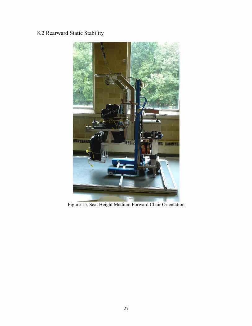
8.2 Rearward Static Stability
Figure 15. Seat Height Medium Forward Chair Orientation
27
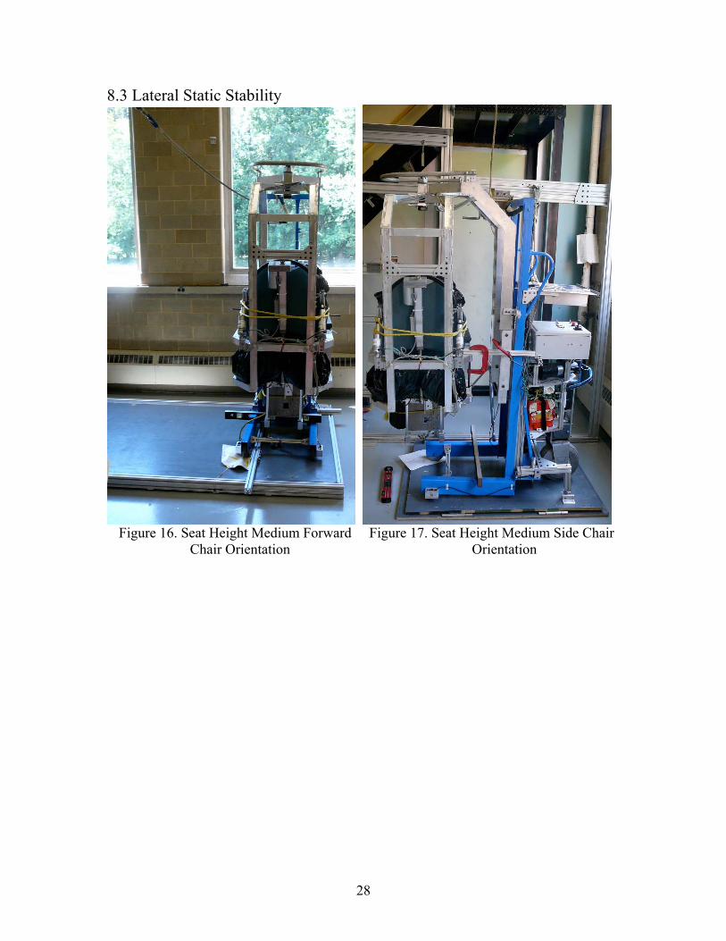
8.3 Lateral Static Stability
Figure 16. Seat Height Medium Forward Figure 17. Seat Height Medium Side Chair
Chair Orientation Orientation
28

Figure 18. Seat Height Medium Rear Figure 19. Seat Height High Forward
Chair Orientation Chair Orientation
29

Figure 20. Seat Height High Side Chair Orientation
30