static and dynamic elastic properties of fractal-cut materials · we introduce a periodic,...
TRANSCRIPT

Static and Dynamic Elastic Properties of Fractal-cut Materials
Valentin Kunin1,2, Shu Yang1, Yigil Cho1, Pierre Deymier4, David J. Srolovitz1,3
1Department of Materials Science and Engineering,2Department of Applied Mathematics and Computational Science,3Department of Mechanical Engineering and Applied Mechanics,
University of Pennsylvania, Philadelphia, PA 19104, USA,4Department of Materials Science and Engineering,The University of Arizona, Tucson, AZ 85721 USA
We investigate the static and dynamic (phononic) elastic behavior of fractal-cut materials. Thesematerials are novel in the sense that they deform by rotation of “rigid” units rather than by strainingthese units, can be fabricated by exploiting a simple cutting paradigm, and have properties that canbe manipulated by control of the cut pattern and its hierarchy. We show that variation of fractal-cutlevel and cut pattern can be exploited to manipulate the symmetry of the elastic constant tensor, theelastic limit of deformation, and, therefore, the elastic response. By studying phonon behavior, wedemonstrate how some cut symmetries naturally open acoustic band gaps. Several of the importantfeatures of the band structure can be directly related to the static elastic properties. Based uponour phonon calculations, we predict the acoustic transmission spectrum of an example fractal-cutstructure and validated it through 3D printing and sound attenuation experiments.
Keywords. Phononic crystals; Acoustic band gaps; Auxetics; Tunable elastic properties.
INTRODUCTION
Heterogeneity in the structure of materials occurs com-monly in natural materials and can be exploited in engi-neering materials to produce combinations of propertiestailored for particular classes of applications. In mostcases, the distributions of phases within materials ex-hibits a substantial degree of randomness. Exceptionsinclude such engineered composites as laminates, alignedfiber composites, and woven structures. For many ap-plications, it is desirable for the phases to have proper-ties from opposite extremes; e.g., strong/brittle phasesand weak/ductile phases. Other examples include caseswhere the elastic constants are either large or zero (i.e.,holes). In this report, we consider the elastic (static anddynamic) properties of a uniform 2D material into whichwe introduce a periodic, hierarchical array of cuts; we re-fer to these as fractal-cut materials [1, 2]. Such materialscan be designed to produce a wide range of interestingand useful properties.
Consider the case of a square sheet with horizontal andvertical cuts. In the example shown in Fig. 1a, a hor-izontal cut is made nearly across the sample leaving aligament at the left and right edges and vertical cuts aremade from the top and bottom surface to just short ofthe center, leaving ligaments at the center. When thisstructure is subject to nearly any external loading, itopens by rotation of section relative to other at the lig-aments/hinges (Fig. 1a). In the limit that the ligamentsize goes to zero, the sections of the material betweencuts remain undeformed during the rotation.Hence, weidealize this material as a set of rigid bodies, connectedby hinges (in 2D or 3D) or possibly universal joints (in3D). This process of separating the material into rotatingblocks can be repeated in a hierarchical form by cutting
the previously rigid/rotatable blocks. If this is done adinfinitum, the resultant structure is a fractal (see Fig.1). Such structures have novel mechanical and dynami-cal properties associated with these two central features;rotatable units and structure across a range of scales.
Simple rotatable structures [3] can produce materialswith negative Poisson ratios (i.e., auxetics) [4–6]; fractal-cut geometries can give rise to extremely large dilata-tions [1, 2]. Such rotations are central to the auxeticbehavior of several perovskite structures [7]. One natu-ral consequence of the extremely large dilatations achiev-able with fractal-cut sheets is their ability to wrap non-zero Gauss curvature objects without wrinkling or tear-ing even when the matrix material is elastically rigid [1].
In addition to interesting elastic/geometric properties,fractal-cut materials also exhibit interesting dynamic(phononic) properties. Since our fractal-cut materialsare periodic, there is a possibility that such structuresmay exhibit band gaps in the phonon spectrum (i.e., fre-quency ranges in which sound does not propagate); suchperiodic metamaterials are known as phononic crystals.The phononic band structure is dictated by the acousticproperties of the constituent materials and their spatialdistribution (in the present case, one phase is solid andthe other is air/vacuum). Unit cell geometries that havebeen exploited in the design of phononic crystals varyfrom very simple [8] to complex [9], including fractals[10–12].
The most obvious application of phononic crystals isin sound insulation (e.g., [13]); however, the high cost ofmanufacturing such periodic structures makes most suchapplications untenable. However, acoustic metamaterialshave a number of other interesting applications includingwaveguides [14] in which sound can be channeled into dif-ferent directions with little energy loss, phononic lenses
2
[15] akin to optical lenses, and devices which exploit neg-ative refraction [16].
One important challenge in acoustic applications is todesign metamaterials such that the band gaps fall intothe frequency range of interest. For acoustic applica-tions, this is below 1 kHz. However, since vibrationalfrequencies scale inversely with unit cell size; 1 kHz com-monly implies meter length scales. Such scales are usu-ally impractical; hence, an important challenge is to de-sign materials with wide, low frequency band gaps and ofreasonable size. While recent advances based upon reso-nant structures have pushed band gaps into the desiredlow frequency region [17], the resultant band gaps are toonarrow for many applications. Since fractal-cut materi-als can be designed with tunable elastic properties, weinvestigate here how such materials can be designed tomanipulate acoustic properties. As we demonstrate be-low, elastic properties can be used as a simple predictorof several important features of the dynamical responseof these materials.
In this paper, we report how the elastic (static anddynamic) properties of such rotatable, fractal-cut struc-tures vary with degree of hierarchy, cut-pattern symme-try, and hinge properties. We begin with an analysis ofthe geometric properties of rotatable hinge, fractal-cutstructures and then analyze the impact of finite hingestiffness in order to predict the elastic behavior (elasticconstants) of such structures. Since real fractal-cut ma-terials will always have finite ligament sizes, we performfinite element analyses in order to determine the corre-lation between hinge stiffness and ligament geometriesin elastic materials (where both the ligament and blocksare made from the same material). Next, we consider dy-namic elastic properties by analyzing sound propagationthrough these materials - determining the phonon bandstructure.We then exploit 3D printing to manufacture afractal-like structure and measure its acoustic propertiesto compare with our predictions. Finally, we examine thecorrelation between the static and dynamic elastic resultsin order to provide guidance for the design of such mate-rials.
STATIC ELASTIC PROPERTIES
In this paper, we consider square and hexagonalunit cell structures repeated to produce (square andKagome [18–20]) lattices [1]. We first focus on squarelattices. Consider splitting a square into four smallersquares, connected by hinges (Fig. 1a) to form a “level1 square lattice” (Fig. 1d). If the squares are perfectlyrigid and the hinges are of zero size, this structure hasonly one degree of freedom (i.e. the angle between twoadjacent squares describes the entire lattice). If the lat-tice is elongated in any (for example, horizontal) direc-tion, the strain in the orthogonal (vertical here) direction
(a) (b) (c)
(d) (e) (f)
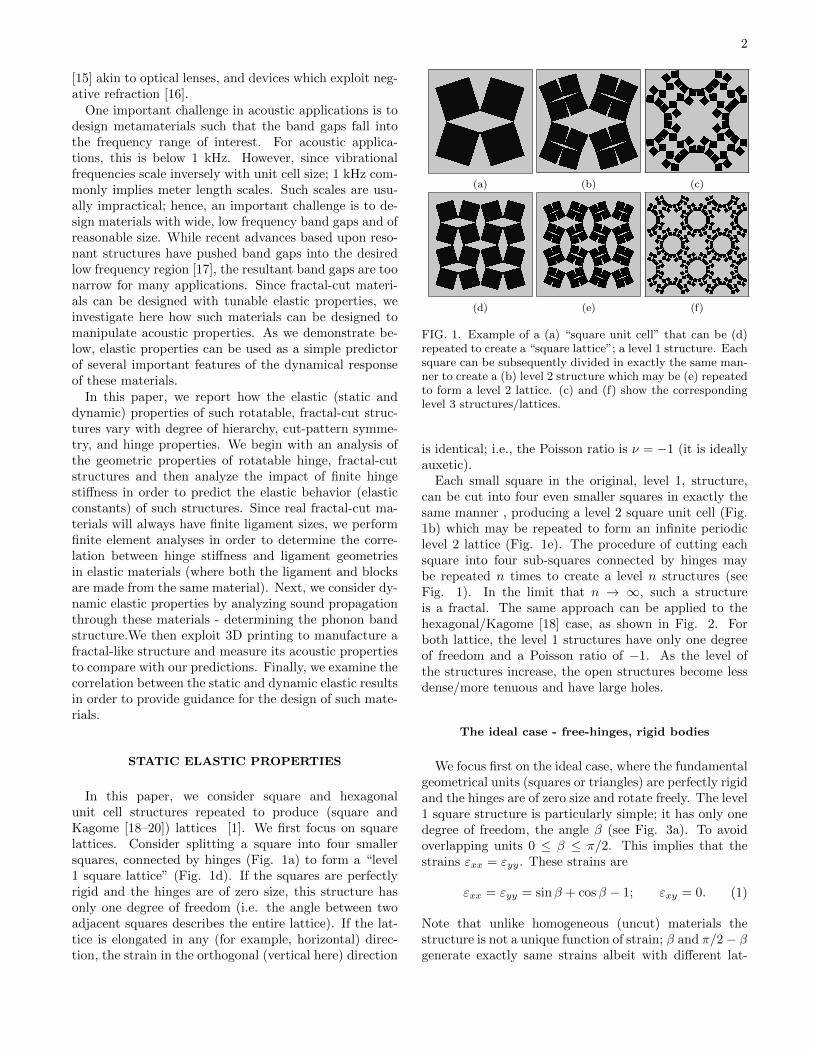
FIG. 1. Example of a (a) “square unit cell” that can be (d)repeated to create a “square lattice”; a level 1 structure. Eachsquare can be subsequently divided in exactly the same man-ner to create a (b) level 2 structure which may be (e) repeatedto form a level 2 lattice. (c) and (f) show the correspondinglevel 3 structures/lattices.
is identical; i.e., the Poisson ratio is ν = −1 (it is ideallyauxetic).
Each small square in the original, level 1, structure,can be cut into four even smaller squares in exactly thesame manner , producing a level 2 square unit cell (Fig.1b) which may be repeated to form an infinite periodiclevel 2 lattice (Fig. 1e). The procedure of cutting eachsquare into four sub-squares connected by hinges maybe repeated n times to create a level n structures (seeFig. 1). In the limit that n → ∞, such a structureis a fractal. The same approach can be applied to thehexagonal/Kagome [18] case, as shown in Fig. 2. Forboth lattice, the level 1 structures have only one degreeof freedom and a Poisson ratio of −1. As the level ofthe structures increase, the open structures become lessdense/more tenuous and have large holes.
The ideal case - free-hinges, rigid bodies
We focus first on the ideal case, where the fundamentalgeometrical units (squares or triangles) are perfectly rigidand the hinges are of zero size and rotate freely. The level1 square structure is particularly simple; it has only onedegree of freedom, the angle β (see Fig. 3a). To avoidoverlapping units 0 ≤ β ≤ π/2. This implies that thestrains εxx = εyy. These strains are
εxx = εyy = sinβ + cosβ − 1; εxy = 0. (1)
Note that unlike homogeneous (uncut) materials thestructure is not a unique function of strain; β and π/2− βgenerate exactly same strains albeit with different lat-

3
(a) (b) (c)
(d) (e) (f)
FIG. 2. Examples of (a) level 1, (b) level 2, and (c) level3 Kagome unit cells that are nearly closed. (d), (e) and (f)show the corresponding fully stretched structures (scaled tofit in the same size boxes) for which the strains are ε∗ = 1,√
3 = 1.71, and 2√
3− 1/2 = 2.96, respectively.
(a) (b)
FIG. 3. Suggested parameterization of the (a) level 1 and (b)level 2 square lattice.
tice geometries/states. Possible geometrical states oflevel 2 include those of level 1, but because level 2has two degrees of freedom (we parameterize as (β1, β2)0 ≤ β1 ≤ β2 ≤ π/2 in Fig. 3b) many more states areavailable. The corresponding strains are
εxx(β1, β2) = sinβ2 +1
2(cosβ1 + cosβ2)− 1
εyy(β1, β2) = cosβ1 +1
2(sinβ1 + sinβ2)− 1
εxy = 0.
(2)
Some strains may be generated by only one state (setof βs) but, like for level 1, some may be generated by twodifferent states. Figure 4 shows the accessible strains forthe level 2 square lattice as well as the number of statesthat can access each strain. Several states labeled in Fig.4 are shown explicitly in Fig. 5; these states are specialin the following sense. “A” corresponds to the maximumdilatation of level 1. There are two states which generatethe strain “B”; the one shown in Fig. 5b is stable andincompressible while the other, shown in Fig. 5c, is only
FIG. 4. Accessible strains of the level 2 square lat-tice; white indicates inaccessible strain states, red indicatesstrains for which only one state exists and yellow indicatesstrains which may be realized in two ways (sets of βs).Points A (εxx = εyy =
√2− 1), B (εxx = εyy = 1/2), and C
(εxx = (√
5− 1)/2, εyy = 1/√
5) are special and correspondto the structures shown in Fig. 5.
(a) (b) (c) (d)
FIG. 5. Special states of the level 2 square lattice (see Fig.4). (a) generates strain A, (b) and (c) both generate strain Band (d) generates state C.
special in the sense that it corresponds to the same strainas Fig. 5b. “C” corresponds to the maximum uniaxialstrain (in the x-direction).
What is the total number of degrees of freedom of alevel n lattice? It may be estimated as follows. The unitcell of a level n periodic lattice consists of N2(n) = 4n
squares with Nh(n) = (4n+1 + 8)/3 hinges per unit cell.Since each square has three degrees of freedom (twotranslations and one rotation) and each hinge constrainstwo of these, the total number of degrees of freedom is
NDOF (n) = 3N2(n)− 2Nh(n) =4n − 16
3, (3)
where the last expression is applicable at large n. Thisformula does not account for linearly dependent degreesof freedom. The linearly dependent degrees of freedomtend to zero as n → ∞; hence Eq. 3 should be viewedas asymptotic for large n and as approximate at smallern. Clearly, this is a very poor approximation for n = 1(1-exact, −4-estimate), n = 2 (2-exact, 0-estimate), andn = 3 (14-exact, 16-estimate).
What is the maximum strain of a level n structureunder uniform biaxial load? In the state of maximumdilation, each unit cell is 4-fold symmetric (hence, εxx =εyy). The maximum dilatation states for the first 4 levelsare given in Fig. 6 and their strains are shown in Table I.It is unclear whether these strains are finite as n → ∞,

4
(a) (b)
(c) (d)
FIG. 6. States of maximum dilation of the square lattice(scaled to the same size) for n = 1, 2, 3, and 4 in (a)-(d),respectively.
but based on the numerical results for the first severallevels we suspect that they do not.
TABLE I. Maximum dilatational strain for the square lat-tice for several n from analytical and numerical calculationsperformed using the Bullet Physics library [21].
Level n ε∗, analytical form ε∗, numerical value
1√
2− 1 0.41
2 7
2√5− 1 0.57
3 1√2− 1 0.71
4 0.82
We follow the same steps for the Kagome lattice. Level1 may be parameterized with one angle β, as shownin Fig. 7a. To avoid self-penetration, β must satisfy0 ≤ β ≤ 2π/3. As for the square lattice, εxx and εyy areequal:
εxx(β) = εyy(β) =√
3 sinβ + cosβ − 1
εxy = 0.(4)
Strains do not uniquely define the shape of a unit cell;β and 2π/3− β generate the same strains, although theshapes are different (see Fig. 8). For the square lattice,replacing β with π/2 − β was equivalent to rotating theunit cell by π/2, while for the Kagome lattice replacing
(a) (b)
FIG. 7. Parameterization of the Kagome lattice employedhere for (a) n = 1 and (b) 2. The solid black lines indicatemirrors.
(a) (b)
FIG. 8. Two different Kagome level 1 states that generatethe same strains.
β with 2π/3−β is equivalent to rotating the unit cell byπ/3.
The level 1 Kagome lattice has three mirror symme-tries, as shown in Fig. 7a. We employ the parameteriza-tion of the level 2 structure shown in Fig. 7b. In general,the total number of degrees of freedom for the Kagomelattice may be estimated in a manner similar to Eq. 3(N4(n) = 6 · 4n−1 and Nh(n) = 6 · 4n−1 + 3):
NDOF (n) = 3N4(n)− 2Nh(n) = 6(4n−1 − 1
). (5)
As for the square lattice, this estimate is strictly valid inthe limit that n→∞ since it does not remove the linearlydependent degrees of freedom. A detailed analysis of aKagome lattice degrees of freedom was performed in [18].
Unlike for the square lattice, we were able to analyti-cally compute the maximum dilation strain as a functionof level n: ε∗ =
√3(3/2)n−1 − (
√3/2 − 1)22−n − 1. For
large n the maximum dilation strain grows exponentiallywith n (fully stretched states of the first three levels areshown in Fig. 2).
Making it Real(er)
Real materials, of course, are very different from theideal free-hinge model discussed above. In this sectionwe replace the free-hinges with spring-hinges, which isa relatively simple description of the elastic deformationthat occurs in the vicinity of a hinge in a real, cut sheet.We model each hinge as a torsion spring of stiffness κ;i.e., the elastic energy of hinge i is Ui = 2κ(βi − β0
i )2,where βi and β0
i is the half angle between a particularpair of rigid bodies (Fig. 3a) and that angle for whichthe torque is zero (we omit the subscript i for level 1

5
structures). Unlike for free-hinges, here materials canstore elastic energy and their elastic constants are, ingeneral, non-zero. The potential energy per unit cell forthe Level 1 square and Kagome lattice are 16κ(β − β0)2
and 18κ(β−β0)2, respectively, and for the Level 2 squareis 32κ
[(β1 − β0
1)2 + (β2 − β02)2 − (β1 − β0
1)(β2 − β02)].
The compliance tensor Sijkl for the square latticestructures has the following form [22]: εxx
εyy2εxy
=
S11 S12 0S11 0
S66
σxxσyyσxy
(6)
The number of independent elastic constants equals thenumber of degrees of freedom up to the point wherethere are more degrees of freedom than independentstrain components (i.e., 3 for the square lattice and 2for the Kagome lattice). Beyond this point, strains donot uniquely define the shape of a free-hinge unit cell.However, with hinge-springs, the strains fully define theshape of the system; the structure may be very complianteven though its primitive elements are rigid.
For the level 1 square lattice structure, there is onlyone degree of freedom S11 = S12 and S66 = 0 and forthe level 2 structure there are two degrees of freedomS11 6= S12 and S66 = 0. We can determine how S11 isrelated to the length of the edge of the primitive square a,the hinge stiffness κ and zero-torque half-angle β0 for thelevel 1 square lattice structure. The strain εxx is relatedto the angle opening ∆β = β − β0 by
εxx =l − l0
l0=
cosβ0 − sinβ0
cosβ0 + sinβ0∆β +O(∆β2), (7)
such that the elastic energy per unit area is
U =8κ∆β2
a2(cosβ0 + sinβ0)2. (8)
From this, we find that the elastic compliance is
S11 = a2 1− sin 2β0
16κ. (9)
In particular, in the fully folded state β0 = 0 andS11 = a2/(16κ).
The compliance tensor for hexagonal lattice structureshave the following form [22]: εxx
εyy2εxy
=
S11 S12 0S11 0
2(S11 − S12)
σxxσyyσxy
(10)
As for the square lattice, the level 1 Kagome structure inthe fully folded state (β0 = 0) has only one degree of free-dom; S11 = S12 =
√3a2/16κ (and, of course, S66 = 0),
where a is a length of the edge of the primitive trian-gle. The level 2 (and all higher level) structure has more
than two degrees of freedom and, therefore, its compli-ance tensor takes the general form.
For β0 6= 0, the level 1 square and Kagome latticesretain their square and hexagonal symmetries. How-ever, for n > 1 this is, in general, not the case. Forexample, the level 2 square lattice possess square sym-metry if β0
1 = π/2− β02 , but rectangular symmetry for
β01 6= π/2− β0
2 (see Fig. 3b). Higher levels can also haveoblique or rhombic symmetries.
Porous structures are often studied in the context ofauxetic (negative Poisson ratio ν) materials [23]. Forthis class of materials, the Poisson ratio is negative forall β0
i = 0. For the level 1 lattices εxx = εyy, andtherefore ν = −1 for β0 6= π/4 in the square latticeand β0 6= π/3 in the Kagome lattice. When β0 = π/4(square) or π/3 (Kagome), ν is not defined, since thematerial is fully stretched and therefore may be neitherstretched nor compressed by applying uniaxial load. Forn > 1, ν is a function of the β0
i ; e.g., for a level 2 squarestructure ν = ν(β0
1 , β02). For a level 2 square lattice, not
only is ν undefined at (β01 , β
02) = (0, arctan 2) (where the
structure is fully stretched in the x-direction), but thelimit does not exist as we approach this point. In fact,ν(β0
1 , β02) may vary from −∞ to ∞ depending on the
path which is used to approach the singular point. Ex-amination of Fig. 4 shows that the slope of the boundary(dεyy/dεxx) =∞ at point C, which implies ν = ±∞ (de-pending on whether this point is approached from aboveor below). This is consistent with the numerical resultsin [2] where they showed that for a structure akin to ourlevel 2, the Poisson ratio can take on large positive ornegative value for a particular set of (β0
1 , β02). Therefore
even for level 2, the Poisson ratio may take on any value.The results presented here suggest that it is possible to
design materials with a prescribed elastic constant tensorand with any value of the Poisson ratio. For example,it is possible to design materials for which some elasticconstants are much smaller than all of the others, forexample, as described in [24, 25].
Making it Really Real
The model presented above, even with the elastic ro-tational hinges, involves several idealizations comparedwith the cut sheet. Of these, the most important are:(1) that the hinges are point hinges, when in fact thecuts leave a finite hinge ligament and (2) the assumptionthat the units are rigid, when in fact they are elastic bod-ies (see [1]). In this section, we discuss the relaxation ofthese two constraints by replacing the rigid blocks withisotropic elastic bodies and by making the hinges of fi-nite size. Examples of such structures with finite hingeligaments are shown in Fig. 9. In these examples, weemploy wedge-shaped hinges of finite radius r and finitezero-torque angle, β0. The mechanical response of such

6
(a) (b)
FIG. 9. Wedge-shaped hinges of normalized radius, r/a, forthe (a) square and (b) Kagome lattices.
(a) (b)
FIG. 10. (a) Torque versus relative hinge angle for the ge-ometry in Fig. 9a with hinge size r = 2 mm, as determinedfrom finite element analysis and the analytical relationshipfor the spring hinge model. (b) The spring hinge stiffnessversus hinge size as determined from FEA. For both figuresβ0 = π/18 and E = 2560MPa and ν = 0.37.
structures must be determined numerically.
We first investigate the relationship between the prop-erties of a structure with such wedge-shaped hinges andthe spring hinges discussed in the previous section in or-der to determine the applicability of the earlier results.We solve for the torque τ - rotation angle β relationshipfor the case where the entire material is linear elastic withelastic constants chosen for polycarbonate; i.e., the ma-terial used in our experimental work, VisiJet c© SL Clear[26] (density ρ = 1.17g/cm3, and isotropic linear elasticconstants E = 2560MPa and ν = 0.37). The numericalsolutions are obtained using linear elastic finite elementanalysis (i.e., COMSOL 4.4 [27]) in plane strain (i.e., weassume the structure is infinitely thick in the directionnormal to the plane of the cuts - this assumption is con-sistent with our experimental geometry used in the nextsection).
Figure 10a shows the relation between the torque perunit length and angle β for the wedge-shaped hinge inFig. 9. The torque is a linear function of relative angleβ−β0, for small relative angle. However, at larger angle,the torque grows in a sub-linear manner. In the spring-hinge model, the torque is a linear function of angle:τ = 2κ(β − β0). The two curves agree well (within 10%)for relative angles 2(β − β0) < 0.12π = 22◦. Clearly, thespring hinge model accurately represents the real struc-
ture for small deformation. We correlate the hinge stiff-ness in the elastic hinge and wedge-shape hinge (finiteelement) models as a function of hinge size in Fig. 10b.To leading order in r, the spring hinge stiffness scales withradius as κ ∝ r2. Hinge stiffness also depends on the elas-tic constants of the base material. By comparison of ourwedge hinge results with elastic predictions from discli-nation theory [28], we expect that κ = αEr2 where α isa dimensionless constant. Comparison of this relationwith the finite element result in Fig. 10b, we find thatα = 1.34 for the geometry in Fig. 9a and E = 2560MPaand ν = 0.37.
DYNAMIC ELASTIC PROPERTIES
We now examine the impact of microscopic rotationaldegrees of freedom on sound propagation. In particular,we exploit such rotational degrees of freedom to engineerphononic band gaps (e.g., [6]). To this end, we numericalsolve the wave equation for our 2D fractal-cut materials:
ρ∂2ui∂t2
− ∂
∂xj(cijkl
∂uk∂xl
) = Fi, (11)
where Fi is a body force, ρ is the density, u is dis-placement, t is time, and cijkl = s−1
ijkl are elementsof the elastic stiffness tensor that depend on location(i.e., they are zero in the holes between the blocks ofthe base material and finite within those blocks) - the-ses elastic constants are not the elastic constants of thewhole structure Cijkl = S−1
ijkl, discussed above. We lookfor solutions compatible with (Floquet) periodic bound-ary conditions: ui(x+max, y + nay, z) = ui(x, y, z) ·exp(−ikxmax − ikynay), where ax and ay are the lengthsof a simulation cell in x and y directions, kx and ky are xand y components of wavevector k, and m and n are inte-gers. The numerical solutions were obtained using finiteelement analysis [27]. In the results presented below, wemodel the solid phase as an isotropic elastic body withparameters corresponding to polycarbonate [26]. We donot explicitly consider damping within the solid materialor interactions between the solid material and air.
Dispersion Relations
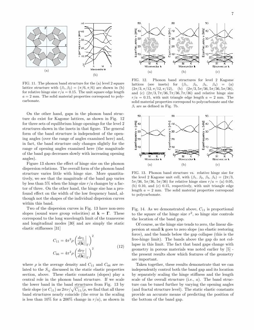
In 2D periodic materials, the wavevectors of interestk are contained within the first Brillouin zone, wherewe use the standard notation to represent directions inreciprocal space (e.g., see [29]). The phonon band struc-ture for the level 2 square lattice structure of Fig. 11a isshown in Figure 11b. Although results vary with level,geometrical state, and hinge size, no low frequency bandgaps are observed for (level 1 and level 2) square lattices(below 50 kHz for this particular sample size).
7
(a)
(b)
FIG. 11. The phonon band structure for the (a) level 2 squarelattice structure with (β1, β2) = (π/6, π/6) are shown in (b)for relative hinge size r/a = 0.15. The unit square edge lengtha = 2 mm. The solid material properties correspond to poly-carbonate.
On the other hand, gaps in the phonon band struc-ture do exist for Kagome lattices, as shown in Fig. 12for three sets of equilibrium hinge openings for the level 2structures shown in the insets in that figure. The generalform of the band structure is independent of the open-ing angles (over the range of angles examined here) and,in fact, the band structure only changes slightly for therange of opening angles examined here (the magnitudeof the band gap decreases slowly with increasing openingangles).
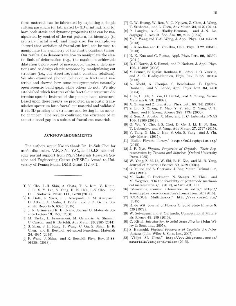
Figure 13 shows the effect of hinge size on the phonondispersion relations. The overall form of the phonon bandstructure varies little with hinge size. More quantita-tively, we see that the magnitude of the band gap variesby less than 5% when the hinge size r/a changes by a fac-tor of three. On the other hand, the hinge size has a pro-found effect on the width of the low frequency band, al-though not the shapes of the individual dispersion curveswithin this band.
Two of the dispersion curves in Fig. 13 have non-zeroslopes (sound wave group velocities) at k = Γ. Thesecorrespond to the long wavelength limit of the transverseand longitudinal modes [30] and are simply the staticelastic stiffnesses [31]
C11 = 4π2ρ
(dνLd|k|
∣∣∣∣Γ
)2
C66 = 4π2ρ
(dνTd|k|
∣∣∣∣Γ
)2(12)
where ρ is the average density and C11 and C66 are re-lated to the Sij discussed in the static elastic propertiessection, above. These elastic constants (slopes) play acentral role in the phonon band structure. If we scalethe lower band in the band structures from Fig. 13 bytheir slope (or C11) as 2πν/
√C11/ρ, we find that all three
band structures nearly coincide (the error in the scalingis less than 10% for a 200% change in r/a), as shown in
(a) (b) (c)
FIG. 12. Phonon band structures for level 2 Kagomelattices (see insets) for (β1, β2, β3, β4) = (a)(2π/3, π/12, π/12, π/12), (b) (2π/3, 5π/36, 5π/36, 5π/36),and (c) (2π/3, 7π/36, 7π/36, 7π/36) and relative hinge sizer/a = 0.15, with unit triangle edge length a = 2 mm. Thesolid material properties correspond to polycarbonate and theβi are as defined in Fig. 7b.
(a) (b) (c)
FIG. 13. Phonon band structure vs. relative hinge size forthe level 2 Kagome unit cell, with (β1, β2, β3, β4) = (2π/3,5π/36, 5π/36, 5π/36) for relative hinge sizes r/a = (a) 0.05,(b) 0.10, and (c) 0.15, respectively, with unit triangle edgelength a = 2 mm. The solid material properties correspondto polycarbonate.
Fig. 14. As we demonstrated above, C11 is proportionalto the square of the hinge size r2, so hinge size controlsthe location of the band gap.
Of course, as the hinge size tends to zero, the linear dis-persion at small k goes to zero slope (no elastic restoringforce), and the bands below the gap collapse (this is thefree-hinge limit). The bands above the gap do not col-lapse in this limit. The fact that band gaps change withgeometry in porous materials was noted earlier by [5] -the present results show which features of the geometryare important.
Taken together, these results demonstrate that we canindependently control both the band gap and its locationby separately scaling the hinge stiffness and the lengthscale of the overall structure (i.e., a). The band struc-ture can be tuned further by varying the opening angles(and fractal structure level). The static elastic constantsprovide an accurate means of predicting the position ofthe bottom of the band gap.

8
FIG. 14. Phonon band structures from Fig. 13 in which thefrequency was scaled by 2π(ρ/C11)1/2.
FIG. 15. Numerical model for computing transmission spec-trum of a 3 unit cells thick (in the x-direction) structure.Black regions correspond to perfectly matched layers (PML),and input and output elastic energies were each integratedover the left-hand side (red) and right-hand side (blue) squareblocks, respectively. A force, sinusoidally varying in time, wasapplied to the left edges of the red blocks.
Transmission Spectra
The phonon band structures in the previous sectionwas determined based upon a periodic structure. Onthe other hand, most acoustic properties of interest aremeasured for finite samples. For example, one commonmeasurement is of the acoustic transmission spectrum;the transmission coefficient T is the ratio of the outputacoustic energy to the input acoustic energy through afinite thickness sample.
We examine the transmission spectrum for the level2 Kagome lattice (periodic in y, three unit cells in x)as shown in Fig. 15. The simulations were, again,performed using the finite element package COMSOL4.4 [27] . The sound was input into the structure througha perfectly matched layer (PML, shown in black), in orderto avoid wave reflection from the boundary, via applica-tion of a harmonic force.
Figure 16 shows the transmission spectrum for thepolycarbonate model in Fig. 15. This figure showsthat there is substantial transmission at low frequency
FIG. 16. Transmission spectrum for the polycarbonate modelin Fig. 15. The corresponding band structure is shown in Fig.12b.
and again at high frequency. However, between thesetwo frequency ranges, a large range of frequencies existfor which there is no acoustic energy transmission (i.e.,a phononic band gap). Comparison of this transmis-sion spectrum with the phonon band structure in Fig.12b (i.e., β1 = 2π/3, β2 = 5π/36, β3 = 5π/36, andβ4 = 5π/36) shows the origin of the transmission spec-trum peaks and gaps.
Experimental Comparison
In order to validate the acoustic property predictions,above, we manufactured a level 2 Kagome structure,akin to that shown in Fig. 12a. The sample was pro-duced by 3D printing (3D Systems ProJet 6000) witha polycarbonate-like material VisiJet c© SL Clear [26](ρ = 1.17g/cm3, E = 2560MPa, ν = 0.37). To re-duce costs, the primitive triangular units were hollow,rather than filled (as in Fig. 12a) as seen in Fig. 17a.The entire sample was 3 unit cells thick (4.5 cm) in thex (sound propagation)-direction and 11.5 unit cells (20cm) in the y-direction and 20 cm long in the z-direction(i.e., the sample is square in the directions perpendic-ular to the sound propagation direction); see Fig. 18.The calculated phonon band structure for the periodicpolycarbonate sample is shown in Fig. 17b and the cal-culated frequency-dependent transmission coefficient forthis 3 unit cell thick sample is shown in Fig. 19.
We measure the transmission spectrum of the 3Dprinted sample in a soundproof chamber. The soundwas generated through a speaker driven by a BK Pre-cision 4003A signal generator in a 3-25kHz frequencyrange. The receiving sensor, mounted on the other sideof the sample from the speaker, was a Behringer ECM8000 microphone, the output of which was amplified andrecorded on a Tektronix TDS 540 oscilloscope. Thetransmission coefficient is the ratio between the sound in-tensities registered by the microphone with and withoutthe sample. The results are compared with the numerical

9
(a)
(b)
FIG. 17. The unit cell (a) and calculated phonon band struc-ture (b) of the 3D-printed polymer structure with r/a = 0.15,β1 = 2π/3, and β2 = β3 = β4 = π/12.
(a)
(b)
FIG. 18. 3D printed sample. In the experiment, sound prop-agates along the x-direction.
prediction in Fig. 19.
The finite element analysis reproduces the general formand frequency range of the experimental transmission atlow frequency. Both the FEA and experiments also showthe transmission coefficient going to zero below 10 kHz.However, while the FEA calculations show a pronouncedpeak in the transmission coefficient between 18 and 25kHz, no such peak is observed in the experiment.
The missing high frequency peak in the transmissionspectrum in the experiment may be associated with theneglect of one or more of the following factors in the
FIG. 19. The transmission spectra from the numerical model(red curve) and the experimental measurement (blue) for sam-ple in Fig. 18.
FEA calculations: (1) solid-air interactions, (2) soundpropagation through and dissipation in the air, (3) dissi-pation (damping) within the polycarbonate, and (4) out-of-plane bending (drumhead-like) modes in the sample.Of these, we expect that the neglect of damping is themost important effect at high frequency. Unfortunately,no damping data is available for our polycarbonate inthe correct frequency range. High frequency dampingdata on a similar material is available [32] in the 2-10MHz frequency range. This data suggests that dampinggrows linearly with frequency (in this range). Extrapo-lating this data to frequencies of interest here suggeststhat this damping is too small to cause significant at-tenuation at 22 kHz for the sample size employed here.If the material were a uniform plate, we would expectthe damping associated with air to be too small to ac-count for the present observations. However, we notethat our material is extremely porous; that is, the air-polycarbonate surface area is very much larger than ifthe same mass of polycarbonate was in the form of a ho-mogeneous plate. This large area would imply greatlyenhanced damping. We suspect that this explains whythe high frequency peak seen in the simulations if absentin the experimental transmission spectrum (Fig. 19).
Nonetheless, the fact that the transmission coefficientgoes to zero (at a frequency similar to the predictions)is clear evidence of a phononic band gap in these ma-terials. Unfortunately, we are unable to experimentallycharacterize its size. We consider this confirmation of themain theoretical predictions (albeit not strong quantitiveconfirmation).
CONCLUSION
In this paper, we investigated the static and dynamicelastic response of fractal-cut materials. These materialsare novel in the sense that (a) they deform by rotationof “rigid” units rather than by straining these units, (b)
10
these materials can be fabricated by exploiting a simplecutting paradigm (or fabricated by 3D printing), and (c)have both static and dynamic properties that can be ma-nipulated by control of the cut pattern, its hierarchy (toarbitrary fractal level), and hinge size. For example, weshowed that variation of fractal-cut level can be used tomanipulate the symmetry of the elastic constant tensor.Our results also demonstrate how to manipulate the elas-tic limit of deformation (e.g., the maximum achievabledilatation before onset of macroscopic material deforma-tion) and to design elastic response by manipulating cutstructure (i.e., cut structure/elastic constant relations).We also examined phonon behavior in fractal-cut ma-terials and showed how some cut symmetries naturallyopen acoustic band gaps, while others do not. We alsoestablished which features of the fractal-cut structure de-termine specific features of the phonon band structure.Based upon these results we predicted an acoustic trans-mission spectrum for a fractal-cut material and validatedit via 3D printing of a structure and testing in an acous-tic chamber. The results confirmed the existence of anacoustic band gap in a subset of fractal-cut materials.
ACKNOWLEDGEMENTS
The authors would like to thank Dr. In-Suk Choi foruseful discussion. V.K, S.Y., Y.C., and D.J.S. acknowl-edge partial support from NSF/Materials Research Sci-ence and Engineering Center (MRSEC) Award to Uni-versity of Pennsylvania, DMR Grant 1120901.
[1] Y. Cho, J.-H. Shin, A. Costa, T. A. Kim, V. Kunin,J. Li, S. Y. Lee, S. Yang, H. N. Han, I.-S. Choi, andD. J. Srolovitz, PNAS 111, 17390 (2014).
[2] R. Gatt, L. Mizzi, J. I. Azzopardi, K. M. Azzopardi,D. Attard, A. Casha, J. Briffa, and J. N. Grima, Sci-entific Reports 5, 8395 (2015).
[3] J. N. Grima and K. E. Evans, Journal Of Materials Sci-ence Letters 19, 1563 (2000).
[4] M. Taylor, L. Francesconi, M. Gerendas, A. Shanian,C. Carson, and K. Bertoldi, Adv Mater. 26, 2365 (2014).
[5] S. Shan, S. H. Kang, P. Wang, C. Qu, S. Shian, E. R.Chen, and K. Bertoldi, Advanced Functional Materials24, 4935 (2014).
[6] P. Wang, J. Shim, and K. Bertoldi, Phys. Rev. B 88,014304 (2013).
[7] C. W. Huang, W. Ren, V. C. Nguyen, Z. Chen, J. Wang,T. Sritharan, and L. Chen, Adv Mater. 24, 4170 (2014).
[8] P. Langlet, A.-C. Hladky-Hennion, and J.-N. De-carpigny, J. Acoust. Soc. Am. 98, 2792 (1995).
[9] Y.-F. Wang and Y.-S. Wang, J. Appl. Phys. 114, 043509(2013).
[10] L. Xiao-Jian and F. You-Hua, Chin. Phys. B 22, 036101(2013).
[11] N.-K. Kuo and G. Piazza, Appl. Phys. Lett. 99, 163501(2011).
[12] R. C. Norris, J. S. Hamel, and P. Nadeau, J. Appl. Phys.103, 104908 (2008).
[13] Y. Pennec, B. Djafari-Rouhani, H. Larabi, J. O. Vasseur,and A. C. Hladky-Hennion, Phys. Rev. B 68, 104105(2008).
[14] A. Khelif, A. Choujaa, S. Benchabane, B. Djafari-Rouhani, and V. Laude, Appl. Phys. Lett. 84, 4400(2004).
[15] J. Li, L. Fok, X. Yin, G. Bartal, and X. Zhang, NatureMaterials 8, 931 (2009).
[16] X. Zhang and Z. Liu, Appl. Phys. Lett. 85, 341 (2004).[17] Z. Liu, X. Zhang, Y. Mao, Y. Y. Zhu, Z. Yang, C. T.
Chan, and P. Sheng, Science 289, 1734 (2000).[18] K. Sun, A. Souslov, X. Mao, and T. C. Lubensky, PNAS
109, 12369 (2012).[19] G. Wu, Y. Cho, I.-S. Choi, D. Ge, J. Li, H. N. Han,
T. Lubensky, and S. Yang, Adv Mater. 27, 2747 (2015).[20] Y. Tang, G. Lin, L. Han, S. Qiu, S. Yang, and J. Yin,
Adv Mater. (2015).[21] “Bullet Physics library,” http://bulletphysics.org/
(2015).[22] J. F. Nye, Physical Properties of Crystals: Their Rep-
resentation by Tensors and Matrices (Oxford UniversityPress, 1985).
[23] W. Yang, Z.-M. Li, W. Shi, B.-H. Xie, and M.-B. Yang,Journal of Materials Science 39, 3269 (2004).
[24] G. Milton and A. Cherkaev, J. Eng. Mater. Technol 117,483 (1995).
[25] M. Kadic, T. Buckmann, N. Stenger, M. Thiel, andM. Wegener, “On the feasibility of pentamode mechani-cal metamaterials,” (2012), arXiv:1203.1481.
[26] “Measuring acoustic attenuation in solids,” http://
iowadoppler.com/documents/attenuation.pdf (2015).[27] “COMSOL Multiphysics,” http://www.comsol.com/
(2015).[28] R. de Wit, Journal of Physics C: Solid State Physics 5,
529 (1972).[29] W. Setyawana and S. Curtarolo, Computational Materi-
als Science 49, 299 (2010).[30] C. Kittel, Introduction to Solid State Physics (John Wi-
ley & Sons, Inc., 2005).[31] S. Haussuhl, Physical Properties of Crystals: An Intro-
duction (John Wiley & Sons, Inc., 2007).[32] “Visijet SL Clear,” http://www.3dsystems.com/es/
materials/visijet-sl-clear (2015).