static and dynamic analysis of boiler supporting structure ....pdf · steel tubular (cfst) column...
TRANSCRIPT

International Journal of Science and Research (IJSR) ISSN (Online): 2319-7064
Impact Factor (2012): 3.358
Volume 3 Issue 8, August 2014 www.ijsr.net
Licensed Under Creative Commons Attribution CC BY
Static and Dynamic Analysis of Boiler Supporting Structure Designed Using Concrete Filled Square
Steel Tubular Columns and Comparison with Structural Steel Columns
Harikrishna .T1,*, Penchal Reddy .M2, Baskar .K3
1Senior Engineer, Fossil Boiler Division, BHEL, Trichy-14, India
2Manager, Fossil Boiler Division, BHEL, Trichy-14, India
3Associate Professor, National Institute of Technology, Trichy-15, India
Abstract: Boiler supporting structure is one of the most important structures employed in any power plant project. A typical boiler supporting structure will be of 100m height subject to a concentrated load in the range of 15000tons to 20000tons hung from the top. The distributed loads attached to the rest of the portion (i.e. from 0m to 100m) are comparatively less and therefore, this type of structure is typically like an inverted pendulum with huge mass attached at the top. These kinds of structures are highly sensitive to lateral and dynamic loads. In the present day Indian scenario, the boiler supporting structures are designed using huge Plus columns made with two major I-sections in the order of 1.0m to 1.2m web depth with a typical web and flange thicknesses in the order of 16mm to 63mm. As a typical once through supercritical boiler supporting structure consists of around 25 to 45 columns of such mega size, such structures becomes more expensive in terms of money and fabrication time. In view of optimizing the structural steel usage and to develop an efficient structural system, a theoretical attempt is made in this study through design of such structures using concrete filled square steel tubular column. Typical boiler structure is modeled using structural analysis program and analyzed for various conditions such as various seismic zones, wind zones, different load combinations and various section sizes. Dynamic response of the structure is studied. The story drift of the structure is estimated at various levels and compared with that of structure made using Plus I-column. Typical cost comparison also made to study the effectiveness of the project. This paper describes the complete analytical procedure along with results and conclusions. Keywords: Boiler supporting structure, concrete filled square steel tubular column, Plus-I column, wind, seismic, power plant 1. Introduction In a thermal power plant, Boiler supporting structure forms 25% of the total weight of a steam generator i.e., in the range of 12000 to 15000 MT and the columns forms 25% of the weight of boiler supporting structure i.e., in the range of 3000 to 3750 MT. Boiler supporting structure transmits the entire pressure parts and non pressure parts load to the foundation through a structural system network consisting of column, beams, bracings and ceiling structure. In the boiler supporting structure, columns are subjected to heavy axial compressive loads in the range of 300 to 3500 MT and at present these are designed using Plus-I columns. Composite columns are a combination of concrete and steel columns combining the advantages of both types of columns. The concrete filling not only leads to a bearing capacity which is much higher than that of steel columns but it also promotes the resistance against fire. Concrete Filled Square Steel Tubular (CFST) column sections have many excellent structural properties, such as high compressive strength, high cyclic strength, large ductility and large energy absorption capacity. The stiffness of the CFST column is greatly enhanced because the steel, which has a much greater modulus of elasticity than the concrete, is situated farthest from the centroid, where it makes the greatest contribution to the moment of inertia. Increased stiffness, leading to reduced slenderness and increased buckling resistance. The steel tube
of a CFST column confines the encased concrete that in return constraints local buckling of steel tube. Therefore, it is most advantageous to use CFSTs for the columns subjected to the large compressive loading. The steel tube prohibits excessive concrete spalling and CFST column add significant stiffness to a frame compared to traditional steel frame construction. The steel of the CFST section is well plastified under bending because it is located most outside the section. The concrete is held by the steel profile and cannot split away even if the ultimate concrete strength is reached. As far as the ductility and the rotation capacity are concerned, concrete filled steel hollow section columns show the best behavior compared to other types of composite columns. Braced frames are an ideal use for CFST column because of their high compressive strength and stiffness. In the present study, the Boiler structure is analyzed designed and estimate is done for two different cases. In these two cases, only the column sections are changed i.e. Case I with Plus-I columns, Case II with Concrete Filled Square Steel Tubular (CFST) columns (see Fig.1). For modeling and analysis of boiler supporting structure, STAAD-Pro software is used. Design of columns is carried out using excel programming and from obtained result, cost comparison is made between Plus-I columns and CFST columns. In both the cases, limit state method of design is adopted. Design of Plus-I columns is carried out as per Indian code, IS-800:2007[10] and design of CFST columns is carried out as
Paper ID: 02015607 1254

International Journal of Science and Research (IJSR) ISSN (Online): 2319-7064
Impact Factor (2012): 3.358
Volume 3 Issue 8, August 2014 www.ijsr.net
Licensed Under Creative Commons Attribution CC BY
per Euro code-4[9], which incorporates latest research on composite construction. Comparative study includes natural time period of the structure, base shear, story drift of the boiler structure and cost comparison of columns. From the results it is found that boiler structure with CFST columns is economical than Plus-I columns in terms of cost.
Figure 1: Typical Column sections used
2. Literature Review A brief review of the research carried out in recent years related to behavior of concrete filled steel tubular columns is presented here. Under axial load and uni-axial bending, experimental
behavior of pin ended normal strength square concrete filled steel tube columns was investigated by Bridge (1976)[1], Matsui et al. (1995)[2] and Chung et al. (1999)[3]. Test results indicated that the ultimate axial strengths of CFST beam-columns increased with increasing the steel tube thickness. Increasing the loading eccentricity ratio/slenderness ratio reduced the ultimate axial strengths of CFST beam-columns.
Mursi and Uy (2006a)[4] studied the experimental behavior of bi-axially loaded CFST short and slender beam-columns which were constructed from high strength structural steel tubes with yield strength of 690 MPa. Their study indicated that the concrete core delayed the local buckling of thin steel walls. Local buckling occurred at the maximum load and steel plates buckled outward on all faces of a slender column. Test results indicated that the ultimate axial strength of hollow steel short beam-columns under axial load and biaxial bending was significantly increased by the infill concrete which delayed the local buckling of the steel plates in compression.
Hsuan et al (2003)[5] proposed proper material constitutive models for concrete-filled tube (CFT) columns and verified the nonlinear finite element program ABAQUS against experimental data. For Square CFT columns, the tubes do not provide large confining effects to the concrete, especially, when the width-to-thickness ratio is large (greater than 30). Both the lateral confining pressure and the material degradation parameter decrease with an increase in width to thickness ratio (D/t or B/t).
Ehab Ellobody et al (2006)[6] presented an accurate nonlinear finite element model for the analysis of normal and high strength concrete-filled square and RHS compact steel tube columns. The columns strengths, load-axial shortening curves and deformed shapes of the columns have been predicted using the finite element model and generally compared well with the experimental results.
They have reported that the design strengths calculated using the European Code are accurate, except for the concrete-filled RHS compact steel tube columns having the overall depth of the steel tube-to-plate thickness ratio of 40 and the design strengths calculated using the ACI/AS are conservative.
Guo et al (2007)[7] carried out experimental and numerical study (ABAQUS) on bare steel and concrete-filled tubes to investigate the occurrence of local buckling and how different depth-to-thickness ratios affect the response of the steel component. Study suggests that for depth-to-thickness ratios greater than 50, i) effects of local buckling needs to be considered in the design ii) significant reserve in capacity in the post-local buckling range which evidently increases the bearing capacity iii) the initial deformation decreases the buckling capacity iv) the residual stress also decreases the bearing capacity.
Qing Quan Liang (2009)[8] performed investigation on the ultimate strength and ductility of high strength thin-walled CFST beam-columns with local buckling effects under combined axial load and biaxial bending using the Performance-based analysis (PBA) technique. The PBA technique accounts for the effects of geometric imperfections, residual stresses, strain hardening, local buckling and concrete confinement on the behavior of high strength thin walled CFST beam-columns. Increasing the depth-to-thickness ratio significantly reduces the section's axial performance, axial ductility, flexural stiffness and strength, curvature ductility, and section interaction performance of thin-walled high strength CFST beam-columns. Increasing the concrete compressive strength considerably reduces the section's axial performance, axial ductility, and section interaction performance but remarkably increases their stiffness, axial load and moment capacities. Increasing the steel yield strength increases the section's axial performance, sectional interaction performance and axial load and moment capacities but only slightly reduces their axial and curvature ductility. Increasing the axial load level greater than 40% of the ultimate axial load significantly reduces the moment capacity and curvature ductility of high strength thin-walled CFST beam-columns.
3. Load Details and Structural data A Once Through Super Critical (OTSC) boiler supporting structure which is situated in earthquake zone-II as per Indian standard IS: 1893-2002[15] and wind speed 47m/s as per IS: 875(Part 3)-1987[13] is considered for this comparative study. The plan dimension and height of structure is 53.35mx92.20m and 90.5m (refer Fig.2).The study is carried out on the same structural plan for both the cases. The basic loading for both the cases are kept same. Structure is designed for permanent loads, imposed loads, lateral buckling and action due to wind/seismic forces. The most unfavorable combinations of the above mentioned force actions had considered as required by IS: 875 (Part 5) – 1987[14].
Paper ID: 02015607 1255

International Journal of Science and Research (IJSR) ISSN (Online): 2319-7064
Impact Factor (2012): 3.358
Volume 3 Issue 8, August 2014 www.ijsr.net
Licensed Under Creative Commons Attribution CC BY
3.1 Dead Loads The dead loads like boiler weight including water filled water walls, economizer water filled bank tubes, 300mm ash build-up in pent house with ash density of 1300kg/m3, equipment weight, structure own weight, other loads like ash water piping, supply ash and instrument air piping, service water piping etc., cantilever loads of not less than 500kg/m at a distance of 1200mm from the external face of the column on both sides of the boilers for supporting cable trays, pipe load and contingent load (including scaffolding ). Dead loads are calculated as per IS: 875 (Part 2)-1987[11]. 3.2 Live Loads As per IS: 875 (Part 2)-1987[12], Imposed floor loads available for the power stations. 500 kg. Per Square meter (Sq.m) on the grating or the
chequered plate of walkways and stairs. 1000 kg. Per Sq.m. on the grating or the chequered plate
of operating floors. 75 kg. Per Sq.m. on roof covering. Side cladding loads Interconnection platform loads at various levels. Considering that the platform live loads never reach their maximum values at the same time on all the points of the structure concerned, these live loads are reduced according to IS:875 (Part 2)-1987[12]. 3.3 Wind Loads Dynamic wind analysis using Gust Factor or Gust Effectiveness Factor method is carried out as per IS: 875(Part 3)-1987[13]. However, a minimum design wind pressure of 1.5 KN/Sq.m is considered. 3.4 Seismic Loads Dynamic analysis of the structure is done as per Response Spectrum Method for Jaipur region (Zone-II), Medium soil. Complete Quadratic Combination (CQC) modal combination method is used. The basic value determination of the seismic action is carried out according IS: 1893 (part 1 and part4)-2002[15]. 3.5 Loads and Load combinations
Type of Loads
1. DL: Dead Load including self weight 2. LL: Live Load 3. WL: Wind Load ( in both directions) 4. SL: Seismic Load (corresponding to DL+50%LL) 5. TL: Secondary loads like Climatic temperature
effect. ( 25C)
Load Combinations 1. DL + LL 2. DL + LL ± WL/SL 3. DL + LL + TL±WL/SL 4. 0.75 DL±WL/SL
Figure 2: Boiler Structural Plan at 0.00 M
Figure 3: 3D Boiler Structural model in Staad.Pro
Paper ID: 02015607 1256

International Journal of Science and Research (IJSR) ISSN (Online): 2319-7064
Impact Factor (2012): 3.358
Volume 3 Issue 8, August 2014 www.ijsr.net
Licensed Under Creative Commons Attribution CC BY
3.6 Structural data
Table 1: Structural data- Boiler supporting structure. 1. Plan dimension 53.350 x 92.200 M
2. Total height of structure 90.5 M
3. Main Brace Levels- 7 levels 15.00, 28.70, 42.80, 55.40,
64.60, 77.20, 90.00 M
4. Erection joints of column- 6 Nos. 16.50, 30.20, 44.30, 56.90,
66.10, 78.70 M
5. Beam profiles
Rolled Beams : I-125,I-150,I-200, I-250,I-300,I-400,I-450,I-500 & I-600; Welded Plate formed “ I”
Beams
6. Vertical bracing profiles Welded Plate formed Box
“[]” sections
7. Horizontal bracing profiles
Double Angles (Back to Back connected);
Star Angles (Diagonally connected)
8. Grade of steel Indian Standard IS:2062
E250 (Fe410 W) 9. Plate thickness used for structural
profiles 8, 10, 12, 16, 20, 25, 32, 36,
40, 50, 56, 63 mm 10. Class of sections considered Plastic/Compact sections 11. Grade of concrete for CFST
columns M30
4. Design Methodology
The column bases and the erection joints of columns are
assumed as pinned. Hence, no bending moment is acting at column base for any of the column.
All the beam-column joints and the joints of vertical and horizontal bracings are assumed as pinned. Accordingly, all end moments are released.
The boiler columns are considered to have lateral support at Main Brace Levels only. Main Brace Levels are acts as Horizontal diaphragm, where all the columns are tied with horizontal beams and horizontal bracings in plan, at that level.
For the effective cost comparison of boiler columns, the utility ratio is maintained same while designing steel plus-I columns and CFST columns.
Eurocode-4[9] provides two methods for calculation of the resistance of composite columns. The first is a general method which takes explicit account of imperfections, the influence of deflections on the equilibrium (second order theory) and the loss of stiffness if parts of the section become plastic (partially plastic regions). The second is a simplified design method which makes use of the European buckling curves for the influence of instability and on cross-section interaction curves determining the resistance of a section. This method is limited in application to composite column of doubly symmetrical and uniform cross-section over the member length. This method is used in this work.
The effective flexural stiffness (EI)eff of a cross section of a composite column according to Eurocode-4 is given as
(EI)eff = EaIa+KeEcmIc
Ia, Ic - Second moments of area of the structural steel section and the un-cracked concrete section
Ea, Ecm - Stiffness moduli of the structural steel and secant modulus of concrete
Ke - correction factor that should be taken as 0.6 Width to thickness ratio of steel plate for CFST column
sections are maintained equal/less than 30 (i.e. B/t ≤ 30), to have a large confining effect to the concrete.
Material properties for analysis of boiler structure for two cases are considered as below: Table 2: Material properties for typical column sections.
Material Property Steel Plus-I
Column sections CFST Column
sections
Elastic Modulus (E) 2.05x10⁵ N/mm2 0.6175x10⁵
N/mm2 Poisson's Ratio (u) 0.3 0.22
Density 78.50 KN/m3 35 KN/m3 Thermal Coefficient of
Expansion () 1.2x10⁻⁵ /0C 1.0x10⁻⁵ /0C
Damping 2% 3.5%
5. Results Static analysis and dynamic analysis of boiler supporting structure are carried out for two different cases i.e. Case-1 with steel plus-I columns and Case-2 with CFST columns and comparison is made; the following results are drawn from the study.
Figure 4: Natural Time Period vs. Base Shear
From Figure 4, The natural time period of the structure using CFST columns is reduced by 21% due to increased stiffness, whereas the base shear of the structure is increased by 35% and 31% along X-axis and Z-axis respectively due to increased mass, compared with steel Plus-I columns.
Paper ID: 02015607 1257
International Journal of Science and Research (IJSR) ISSN (Online): 2319-7064
Impact Factor (2012): 3.358
Volume 3 Issue 8, August 2014 www.ijsr.net
Licensed Under Creative Commons Attribution CC BY
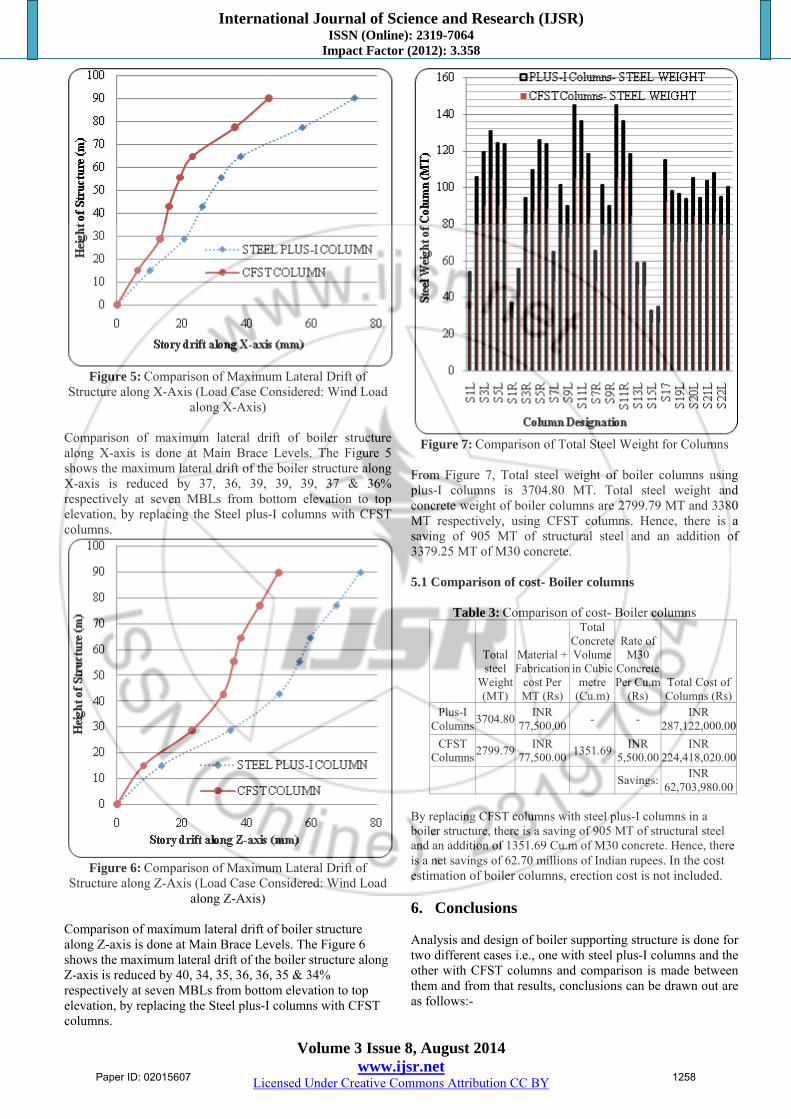
Figure 5: Comparison of Maximum Lateral Drift of
Structure along X-Axis (Load Case Considered: Wind Load along X-Axis)
Comparison of maximum lateral drift of boiler structure along X-axis is done at Main Brace Levels. The Figure 5 shows the maximum lateral drift of the boiler structure along X-axis is reduced by 37, 36, 39, 39, 39, 37 & 36% respectively at seven MBLs from bottom elevation to top elevation, by replacing the Steel plus-I columns with CFST columns.
Figure 6: Comparison of Maximum Lateral Drift of
Structure along Z-Axis (Load Case Considered: Wind Load along Z-Axis)
Comparison of maximum lateral drift of boiler structure along Z-axis is done at Main Brace Levels. The Figure 6 shows the maximum lateral drift of the boiler structure along Z-axis is reduced by 40, 34, 35, 36, 36, 35 & 34% respectively at seven MBLs from bottom elevation to top elevation, by replacing the Steel plus-I columns with CFST columns.
Figure 7: Comparison of Total Steel Weight for Columns
From Figure 7, Total steel weight of boiler columns using plus-I columns is 3704.80 MT. Total steel weight and concrete weight of boiler columns are 2799.79 MT and 3380 MT respectively, using CFST columns. Hence, there is a saving of 905 MT of structural steel and an addition of 3379.25 MT of M30 concrete. 5.1 Comparison of cost- Boiler columns
Table 3: Comparison of cost- Boiler columns
Total steel
Weight(MT)
Material + Fabrication
cost Per MT (Rs)
Total Concrete Volume in Cubic
metre (Cu.m)
Rate of M30
ConcretePer Cu.m
(Rs) Total Cost of Columns (Rs)
Plus-I Columns
3704.80INR
77,500.00 - -
INR 287,122,000.00
CFST Columns
2799.79INR
77,500.00 1351.69
INR 5,500.00
INR 224,418,020.00
Savings:
INR 62,703,980.00
By replacing CFST columns with steel plus-I columns in a boiler structure, there is a saving of 905 MT of structural steel and an addition of 1351.69 Cu.m of M30 concrete. Hence, there is a net savings of 62.70 millions of Indian rupees. In the cost estimation of boiler columns, erection cost is not included. 6. Conclusions Analysis and design of boiler supporting structure is done for two different cases i.e., one with steel plus-I columns and the other with CFST columns and comparison is made between them and from that results, conclusions can be drawn out are as follows:-
Paper ID: 02015607 1258

International Journal of Science and Research (IJSR) ISSN (Online): 2319-7064
Impact Factor (2012): 3.358
Volume 3 Issue 8, August 2014 www.ijsr.net
Licensed Under Creative Commons Attribution CC BY
The natural time period of the boiler structure is reduced by 21% using CFST columns compared with steel plus-I columns.
The base shear of the boiler structure got increased by 35% and 31% along X-axis and Z-axis by replacing steel plus-I columns with CFST columns.
The structure with CFST columns shows a reduction in storey drift up to 40% compared to that of Plus-I columns.
Structural steel weight reduction of 905MT is achieved by replacing plus-I columns with CFST columns. But, there is an addition of 1351.69 Cubic meter of M30 concrete that is used in CFST columns.
In the cost estimation of boiler columns, erection cost is not included. As compared to steel plus-I columns there is a net saving of 62.70 million (INR) is noticed when CFST columns are employed for the structure considered.
Present work shows that the use of CFST columns in boiler structures provides considerable cost saving in addition to its better structural performance.
References [1] Bridge, R. Q. (1976). “Concrete filled steel tubular
columns.” School of Civil Engineering, The University of Sydney, Sydney, Australia, Research Report No.R283.
[2] Matsui, C., Tsuda, K. and Ishibashi, Y. (1995). “Slender concrete filled steel tubularcolumns under combined compression and bending.” Proceedings of the 4th Pacific Structural Steel Conference, Singapore, Pergamon, 3(10), 29-36.
[3] Chung, J., Tsuda, K. and Matsui, C. (1999). “High-strength concrete filled square tube columns subjected to axial loading.” The Seventh East Asia-Pacific Conference on Structural Engineering & Construction, Kochi, Japan, 2, 955-960.
[4] Mursi, M. and Uy, B. (2006a). “Behaviour and design of fabricated high strength steel columns subjected to biaxial bending part I: Experiments.” Advanced Steel Construction, 2(4), 286-313.
[5] “Nonlinear analysis of axially loaded concrete-filled tube columns with confinement effect”, Hsuan-The Hu, Chiung-Shiann Huang, Ming-Hsien Wu, and Yih-Min Wu, J.Struct.Eng, Volume 129, Issue 10, October 2003, Pages 1287-1430.
[6] Ehab Ellobody, Ben Young, Dennis Lam (2006) : “Behaviour of normal and high strength concrete filled compact steel tube circular stub columns.” Journal of constructional steel research- J CONSTR STEEL RES, Vol.62, no.7, PP.706-715, 2006.
[7] L.Guo, Sumai Zhang, Wha-Jung Kim, Gianluca Ranzi (2007)- “Behaviour of square hollow steel tubes and steel tibes filled with concrete.” – ELSEVIER Journal, Thin-walled structures 45 (2007), PP. 961-973.
[8] Liang, Qing Quan (2009) Strength and ductility of high strength concrete-filled steel tubular beam-columns. Journal of Constructional Steel Research, 65 (3). pp. 687-698. ISSN 0143-974X
[9] Code and Commentary on Eurocode 4, 2004, “Design of composite steel and concrete structures - Part 1-1: General rules and rules for buildings”.
[10] IS 800-2007, Code of practice for general construction in steel, Bureau of Indian Standard, New Delhi.
[11] IS 875(1987-Part 1), - code of practice for design loads(other than earthquake)for buildings and structures ,Dead loads, Bureau of Indian standards (BIS), New Delhi.
[12] IS 875(1987-Part2), - code of practice for live loads, Bureau of Indian Standards (BIS), New Delhi.
[13] IS 875(1987-Part3), - code of practice for wind loads, Bureau of Indian Standards (BIS), New Delhi.
[14] IS 875(1987-Part5), - code of practice for special loads and combinations, Bureau of Indian Standards (BIS), New Delhi.
[15] IS 1893 (part 1 and part 4)-2002, Criteria for earthquake resistant design of structures, Bureau of Indian Standards (BIS), New Delhi.
Paper ID: 02015607 1259