finite element analysis of beam-cfst column connections ... · finite element analysis of beam-cfst...
TRANSCRIPT

Proceedings of the Tenth Pacific Conference on Earthquake Engineering Building an Earthquake-Resilient Pacific
6-8 November 2015, Sydney, Australia
Finite element analysis of beam-CFST column connections using replaceable buckling restrained fuses (RBRFs) as energy dissipation
device
Y. Oktavianus & H.M. Goldsworthy The University of Melbourne, Melbourne, Australia.
E.F. Gad Swinburne University of Technology, Hawthorn, Australia.
S. Fernando Ajax Engineered Fasteners, Braeside, Australia.
ABSTRACT: The use of a replaceable buckling restrained fuse (RBRF) as an element in a low damage beam-column connection has been examined using finite element analysis (FEA). There are several advantages associated with RBRFs in moment-resisting frames in regions of high seismicity, such as simplicity of fabrication, high energy absorption and reliability in the behaviour. The moment-resisting beam-column connection considered here is a double T-stub type connection from a steel beam to a concrete filled steel tube. The results from FE studies of RBRFs under cyclic loading are presented here. The purpose of this study is to ensure that the fuses will behave as expected when subjected to cyclic displacements representative of a maximum considered earthquake (MCE), i.e. the fuse yields in tension and compression without triggering any reduction in capacity due to buckling in the overall fuse or yielding at the beam flange or T-stub stem. Details of the installation of these fuses and dimensions of fuses that are appropriate for a particular beam size have been proposed.
1 INTRODUCTION
Concrete filled circular hollow sections (CFCHSs) as columns provide high strength and ductility in addition to aesthetic appeal and elimination of the need of formwork. Before the 1994 Northridge earthquake, welded connections were preferred when connecting steel or composite beams to steel universal columns due to the impracticability of using bolted connections and the perceived better hysteretic behaviour with less pinching when compared with the bolted connections. However, in light of the brittle behaviour generated by welded connections (FEMA-351 2000), bolted connections have been the subject of further research (Swanson and Leon 2000). In the case of connection to CFCHS columns the development of various types of blind bolt, i.e. a bolt that can be tightened from only one side, has led to the development of simply constructed and effective moment-resisting connections using these bolts. There are several blind bolts available in the market, such as the Huck high-strength blind bolt (Huck International Inc. 1990), the Lindapter Hollo-bolt (Lindapter International 2012), Flow-drilling (France, Davison and Kirby 1999a), and the Ajax ONESIDE blind bolt (Ajax Engineered Fasteners 2002). The latter has been modified to improve the stiffness of the connection by extending the shank of the bolt and inserting an additional head at the end of the extension. The behaviour of this modified blind bolt, called a headed anchor blind bolt (HABB), both individual and group, has been summarized by Oktavianus et al. (2014, 2015a, 2015b). Having this information, HABBs are chosen to be used here to connect a double T-stub type connection from a steel beam to a concrete filled steel tube.
Some additional modifications, i.e. by adding low damage connections, bracings, or a base isolation system, need to be performed if the structures are to be built in a high seismic region in order to reduce the economic losses after a major earthquake event. This paper will focus on one type of low damage connection called the replaceable buckling restrained fuse (RBRF) as shown in Figure 1. The RBRF is an energy dissipation device made of mild steel bars with a reduced section in the middle of the bars
Paper Number 79

2
(fuse) and steel tubes filled with epoxy or cement grout for preventing the fuse from buckling. This device has been used in New Zealand in the application of precast reinforced concrete frames in the Learning and Research Building at Victoria University in Wellington (Cattanach et al. 2008) and a multi-storey timber building in the Merritt building in Christchurch (Sarti et al. 2013). There are several advantages associated with the use of RBRFs in moment-resisting frames in regions of high seismicity, such as simplicity of fabrication, high energy absorption and reliability in the behaviour (Amaris et al. 2006, Marriott 2009, Sarti et al. 2013).
(a)
(b)
Figure 1. Replaceable buckling restrained fuse (RBRF): (a) schematic with anchorage; (b) FE model-cut view without anchorage
The use of a replaceable buckling restrained fuse (RBRF) as an element in a low damage beam-column connection has been examined using finite element analysis (FEA). Previous experimental results on a single buckling restrained fuse (Sarti et al. 2013) have been used for comparison with corresponding FE models to obtain appropriate material properties for each component of the fuse. Once a good match between experimental work and FEA of a single BRF has been obtained, the whole bottom connection, without the connection of T-stub to the column, has been modelled. The FEA of the bottom connection and that of the T-stub connection to the CFCHS column were separated to reduce the computational time and complexity. Oktavianus et al. (2015b) have performed the FEA of the connection of the T-stub to a CFCHS 457x9.5 and a CFCHS 508x12.7 and used the single RBRF behaviour presented by Sarti et al. (2013) to check the feasibility of its use. However, the T-stub connection to a CFCHS 457x12.7 and the behaviour of RBRFs (both individual or group) in the bottom connection due to cyclic loading (tension and compression) have not previously been analysed using FEA and would be analysed in this research. The purpose of this study is to ensure that the fuses will behave as expected when subjected to cyclic displacements representative of a maximum considered earthquake (MCE), i.e. the fuse yields in tension and compression without triggering any buckling in the overall fuse or yielding at the beam flange or T-stub stem. Details of the installation of these fuses and dimensions of fuses that are appropriate for a particular beam size have been proposed.
2 CASE STUDY
The design example is adopted from a journal paper written by Khoo et al. (2012), particularly section 3.1. This presents a design example for the SCSHJ which relates to a 460 UB 67.1 beam connected to a 530 UB 92.4 internal column, taken from level 1 of a 10 storey MRF in the Te Puni Village Tower Building, Wellington as shown in Figure 2, which currently uses a sliding hinge joint (SHJ) as the energy dissipating device. The building has a normal importance level (Importance level 2 in accordance with AS/NZS 1170.0) and is located at a site with soil class B. Initially the building was analysed using the same sections as those used by Khoo et al. (2012), and making the following assumptions: the thickness of the slab (𝑡𝑡𝑠𝑠𝑠𝑠𝑠𝑠𝑠𝑠) is equal to 0.2 m; density of the concrete (𝜌𝜌𝑐𝑐) is equal to 24.5 kN/m3; the live load (𝑄𝑄) is equal to 3 kPa for each floor except for roof of 1.5 kPa; the floor area for each frame is equal to 27.5 Χ 6 m2; the weight of the façade or perimeter wall (𝐺𝐺𝑓𝑓/𝑝𝑝) is equal

3
to 1 kPa.
The building was then reanalysed substituting CFCHS sections for the open sections in the interior columns. In order to incorporate concrete filled circular hollow sections (CFCHSs) as columns, the open section column previously used has been modified accordingly based on the effective flexural stiffness following Eurocode 4 (CEN 2004) to maintain the natural period of the building. It should be noted that the strength (i.e. axial and bending capacity) of the CFCHS is higher than that of open section. All of the CFCHS columns also have a higher capacity than the steel beams. Table 1 shows the comparison between the frame using open sections and closed sections as interior columns. The new frame (with closed sections as interior columns) has a slightly smaller natural period and slightly higher seismic weight than the original frame with open section columns, therefore, the demand of the moment due to design based earthquake (500 years return period), 𝑀𝑀𝐷𝐷𝐷𝐷𝐷𝐷, of the new frame (249.08 kNm) is higher than that of the original frame (237.6 kNm).
Table 1. Comparison between open section and closed section columns
Note Open sections columns Closed sections columns
Natural period, 𝑇𝑇𝑛𝑛 2.162 s 2.035 s
Total seismic weight, 𝑊𝑊𝑡𝑡 = 𝐺𝐺 + 0.3𝑄𝑄 12535.6 kN 13013.45 kN
Total base shear (considering accidental eccentricity), V
1047 kN 1124.5 kN
�𝑀𝑀𝐷𝐷𝐷𝐷𝐷𝐷𝑚𝑚𝑠𝑠𝑚𝑚� at considered joint (see Figure 2) 237.6 kNm 249.08 kNm
�𝑉𝑉𝐷𝐷𝐷𝐷𝐷𝐷𝑚𝑚𝑠𝑠𝑚𝑚� at considered joint (see Figure 2) 103.1 kN 105.4 kN
(a)
(b)
Figure 2. Building layout: (a) plan view; (b) elevation view (Khoo et al. 2012)
3 HYSTERETIC BEHAVIOUR OF THE CONNECTION
3.1 T-stub to CFCHS
Figure 3 shows the connection layout of a T-stub at the top flange of the steel beam to CFCHS 457x12.7. The top and bottom part of a T-stub at the top of beam flange are shown respectively as section A-A and section B-B in Figure 3. There were 2M20 headed anchor blind bolts (HABBs) with embedment depths of 100 mm and 1M24 through bolt in the top part of a T-stub. Moreover, there were 2M24 HABBs with embedment depths of 120 mm in the bottom part of a T-stub. A reverse configuration of this T-stub has been used at the bottom of the beam flange. It means section A-A will be the bottom bolt line and section B-B will be the top one (see Figure 3). A thickness of 25 mm has been chosen for the curved endplate of T-stub to minimize the prying action.

4
A finite element model has been built and it is similar to the one explained by Oktavianus et al. (2015a) for T-stub connections to CFCHS 457x9.5 and CFCHS 508x12.7. Moreover, because this paper also adopts the same material properties and assumptions used by Oktavianus et al. (2015b), the details of the FE model are not mentioned here.
(a) Front view
(b) Section A-A
(c) Section B-B
Figure 3. Connection layout of T-stub to CFCHS 457x12.7: (a) Front view; (b) Section A-A; (c) Section B-B
Both monotonic and cyclic loading have been applied to the stem of the T-stub shown in Figure 3 and the force versus displacement relationships from those loadings are drawn in Figure 4(a) and (b). Considering two possible locations of the RBRFs which could be either at the top (case 1) or at the bottom (case 2) of the bottom flange of the steel beam as shown in Figure 7, the force acting on the T-stub will vary accordingly. The larger the lever arm, the smaller the force that will be taken by the T-stub. Case 1 and case 2 have lever arm, z, of 426 mm and 562 mm respectively as shown in Figure 7. Moreover, the forces generated by both cases have been shown in Figure 4. Both of the cases generate forces lower than 0.6 of the ultimate capacity of the T-stub connections (i.e. 730 kN for the case considered) which will prevent the development of micro-cracks in the concrete infill and hence retain the stiffness of the anchorage (Oktavianus et al., 2015). Moreover, there is around 25% and 65% spare capacity before reaching 730 kN for case 1 and 2 respectively that could be exploited when the earthquake event is exceeding DBE (500 years return period) and approaching MCE (maximum rotation of 0.04 rad). The moment-rotation relationship of the connection has been developed using two non-linear springs at a distance of z apart. The springs represent the behaviour of the T-stubs with one in tension and the other in compression. Figure 4(c) shows that under DBE, these connections are rigid in a braced frame and semi-rigid in an unbraced frame following the classification defined by Eurocode 3 (CEN 2005).
(a)
(b)
(c)
Figure 4. The behaviour of T-stub connection: (a) full view of force vs displacement relationship; (b) zoom view of force vs displacement relationship; and (c) full view of moment vs rotation
5
3.2 Steel beam to T-stub
3.2.1 FEA of individual RBRF
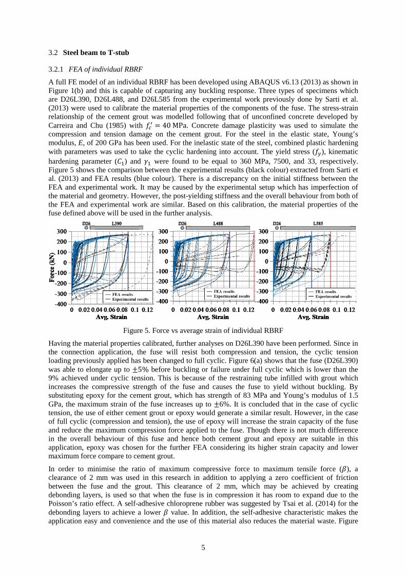
A full FE model of an individual RBRF has been developed using ABAQUS v6.13 (2013) as shown in Figure 1(b) and this is capable of capturing any buckling response. Three types of specimens which are D26L390, D26L488, and D26L585 from the experimental work previously done by Sarti et al. (2013) were used to calibrate the material properties of the components of the fuse. The stress-strain relationship of the cement grout was modelled following that of unconfined concrete developed by Carreira and Chu (1985) with 𝑓𝑓𝑐𝑐′ = 40 MPa. Concrete damage plasticity was used to simulate the compression and tension damage on the cement grout. For the steel in the elastic state, Young’s modulus, E, of 200 GPa has been used. For the inelastic state of the steel, combined plastic hardening with parameters was used to take the cyclic hardening into account. The yield stress (𝑓𝑓𝑦𝑦), kinematic hardening parameter (𝐶𝐶1) and 𝛾𝛾1 were found to be equal to 360 MPa, 7500, and 33, respectively. Figure 5 shows the comparison between the experimental results (black colour) extracted from Sarti et al. (2013) and FEA results (blue colour). There is a discrepancy on the initial stiffness between the FEA and experimental work. It may be caused by the experimental setup which has imperfection of the material and geometry. However, the post-yielding stiffness and the overall behaviour from both of the FEA and experimental work are similar. Based on this calibration, the material properties of the fuse defined above will be used in the further analysis.
Figure 5. Force vs average strain of individual RBRF
Having the material properties calibrated, further analyses on D26L390 have been performed. Since in the connection application, the fuse will resist both compression and tension, the cyclic tension loading previously applied has been changed to full cyclic. Figure 6(a) shows that the fuse (D26L390) was able to elongate up to ±5% before buckling or failure under full cyclic which is lower than the 9% achieved under cyclic tension. This is because of the restraining tube infilled with grout which increases the compressive strength of the fuse and causes the fuse to yield without buckling. By substituting epoxy for the cement grout, which has strength of 83 MPa and Young’s modulus of 1.5 GPa, the maximum strain of the fuse increases up to ±6%. It is concluded that in the case of cyclic tension, the use of either cement grout or epoxy would generate a similar result. However, in the case of full cyclic (compression and tension), the use of epoxy will increase the strain capacity of the fuse and reduce the maximum compression force applied to the fuse. Though there is not much difference in the overall behaviour of this fuse and hence both cement grout and epoxy are suitable in this application, epoxy was chosen for the further FEA considering its higher strain capacity and lower maximum force compare to cement grout.
In order to minimise the ratio of maximum compressive force to maximum tensile force (𝛽𝛽), a clearance of 2 mm was used in this research in addition to applying a zero coefficient of friction between the fuse and the grout. This clearance of 2 mm, which may be achieved by creating debonding layers, is used so that when the fuse is in compression it has room to expand due to the Poisson’s ratio effect. A self-adhesive chloroprene rubber was suggested by Tsai et al. (2014) for the debonding layers to achieve a lower 𝛽𝛽 value. In addition, the self-adhesive characteristic makes the application easy and convenience and the use of this material also reduces the material waste. Figure

6
6(b) shows that at an average strain of 2.5%, specimen D26L390 with zero clearance between the BRF and the epoxy has a 𝛽𝛽 value of 1.52. On the other hand, the same specimen with a clearance of 2 mm between the BRF and the epoxy has a 𝛽𝛽 value of 1.14. Since the smaller 𝛽𝛽 value is desired to avoid excessive compression force in the fuse, a clearance of 2 mm has been used in the following section.
(a)
(b)
Figure 6. Force vs average strain: (a) Due to cyclic tension and full cyclic in specimens with zero clearance between the BRF and the grout/epoxy (b) Full cyclic_epoxy with clearance of 2 mm
between the BRF and the epoxy
3.2.2 Behaviour of the bottom of steel beam to T-stub connection
As mentioned previously, two possible locations of the RBRFs (case 1 and case 2) have been considered as shown in Figure 7. Two RBRFs (one at each side of the beam) were used for case 1 and one RBRF was used for case 2 respectively.
Section A-A
(a)
Section B-B
(b)
Figure 7. Sub assemblage of steel beam to CFCHS column connection (a) case 1; (b) case 2
460 UB 67.1
High strengthstructural bolt
Curved T-stub
Through bolt
Point of rotation
Headed AnchorBlind Bolt (HABB)
RBRFA
CFCHS 457X12.7
StiffenerA High strength
nutHigh strengththreaded bar
Stiffener
z=426 mm
Debonding layers
Beam's webBeam's flange
RBRF anchorEpoxy/grout
Confining tube
Replaceable bucklingrestrained fuse (RBRF)
460 UB 67.1
High strengthstructural bolt
Curved T-stub
Through bolt
Point of rotation
Headed AnchorBlind Bolt (HABB)
RBRF
High strengthnut
B
CFCHS 457X12.7
B
StiffenerHigh strengththreaded bar
Stiffener
z=562 mm Epoxy/groutConfining tube
Beam's webBeam's flange
RBRF anchor
Replaceable bucklingrestrained fuse (RBRF)
Debonding layers

7
Based on the demand and material properties defined in the previous section, the dimension of the RBRF has been calculated considering that two RBRFs and one RBRF will be used in case 1 and 2, respectively. This fuse should be designed to be rigid up to DBE and yielding without failure when the earthquake displacement response exceeds DBE up to MCE. Moreover, the bending capacity of the steel tube has been checked according to NZS 3404 (SNZ 1997) to prevent the buckling of the steel tube. This results in the following dimensions for case 1 and case 2 (dimension for case 2 is shown inside the bracket): 𝐷𝐷𝑓𝑓𝑓𝑓𝑠𝑠𝑓𝑓 = 32.5 (40) mm; 𝐿𝐿𝑓𝑓𝑓𝑓𝑠𝑠𝑓𝑓 = 487.5 (600) mm; 𝐷𝐷𝑓𝑓𝑚𝑚1 = 𝐷𝐷𝑓𝑓𝑚𝑚2 = 42 (52)mm; 𝐿𝐿𝑓𝑓𝑚𝑚1 = 𝐿𝐿𝑓𝑓𝑚𝑚2 = 50 (60) mm, 𝐷𝐷𝑡𝑡𝑓𝑓𝑠𝑠𝑓𝑓,𝑖𝑖𝑛𝑛𝑡𝑡 = 52 (62) mm, 𝐷𝐷𝑡𝑡𝑓𝑓𝑠𝑠𝑓𝑓,𝑓𝑓𝑚𝑚𝑡𝑡 = 62 (72) mm, and 𝐿𝐿𝑡𝑡𝑓𝑓𝑠𝑠𝑓𝑓 =567.5 (700) mm (refer to Figure 1 for the notation). Moreover, epoxy grout was used in this analysis with same grade as mentioned in the previous subsection.
Figure 8 shows the FE model of the connection of the steel beam to the T-stub. Only the stem of the T-stub was included in the model. A fixed boundary condition at the left end of the stem was used since the behaviour of the T-stub to the CFCHS column has been defined in the previous subsection. Stiffeners have been provided at the anchorage to ensure that the steel plate to which the anchorage is welded does not yield and also to minimise deformation and stress concentration. Moreover, additional stiffeners have been provided in the steel beam to prevent local buckling due to stress concentration.
(a)
(b)
Figure 8. FE model of the connection of the steel beam to the T-stub: (a) case 1; (b) case 2
Figure 9 shows the moment-rotation relationships for both cases from FEA. One full cyclic loading up to a rotation of 40 mrad, which is assumed to be the maximum rotation that will occur during maximum credible earthquake (MCE), was applied at the tip of the beam, which is the point of contraflexure, with upward (designated as “T”) or downward (designated as “C”) displacement as the starting point. An additional cyclic loading consisting of 5 cycles under DBE, 1 cycle in between DBE and MCE, and 1 cycle at MCE has been applied to case 2 (designated as “cyclic”). It is shown that there is a lateral torsional buckling in case 1 causing reduction in the negative moment capacity. Though this buckling did not occur in case 2, fly-bracings from the slab to the bottom of the beam (at the end of the beam) may be used to prevent lateral torsional buckling in the beam due to the unsymmetricalities in either the section properties or the loadings. Case 1 was not further analysed in this paper because considering the reserve capacity needed for MCE, case 2 attracts a smaller force to the T-stub due to the larger lever arm and hence will prevent the concrete infill inside the composite column from cracking.
(a)
(b)
Figure 9. Moment vs rotation of the connection: (a) between steel beam and the T-stub; (b) whole connection using superposition (sub assemblage)

8
It is also shown in Figure 9 that the post-yielding compressive stiffness is larger than that of tensile stiffness. However, considering that the steel beams are connected to both sides of the column, it is more appropriate to take the average response resulting from positive and negative moments (designated as “ave”) as shown in Figure 9(b). Moreover, when the average response was compared to the one generated using analytical model suggested by Sarti et al. (2013) for the RBRF and considering a 𝛽𝛽 value of 1.15, there is a good match for the elastic stiffness, yield strength, and the envelope response.
3.3 Steel beam to CFCHS
The total behaviour of the steel beam to CFCHS could be obtained by adding the behaviour of T-stub to CFCHS (section 3.1) and that of steel beam to T-stub (section 3.2.2). However, in the light of the very high stiffness generated by the double T-stub, the additional rotation generated is very small as shown in Figure 9(b). In conclusion, Figure 9(b) also shows that the maximum moment induced at the MCE is less than the design bending capacity of the steel beam. This will keep the beam remains elastic as desired. Moreover, this maximum moment is also less than 1.65 times 𝑀𝑀𝐷𝐷𝐷𝐷𝐷𝐷 which means that this moment is less than 0.6 times the ultimate capacity of the T-stub and hence the anchored blind bolts should retain their strength and stiffness.
4 CONCLUSIONS
The use of replaceable buckling restrained fuses (RBRFs) in connections between steel beams and concrete filled circular hollow sections (CFCHSs) through double curved T-stubs has been studied. The behaviour of the whole connection is built by a superposition of the behaviour of the double T-stub connection to the CFCHS and the behaviour of the connection between the steel beam and the T-stubs. Several key points are summarised as follows:
1. The moment-rotation relationship of the double T-stub to CFCHS connection (ignoring the contribution of the beam) can be categorised as rigid in a braced frame and semi-rigid in an unbraced frame in the case studied.
2. For a single RBRF in the case of cyclic tension, the use of either cement grout or epoxy would generate a similar result. However, in the case of full cyclic (compression and tension), the use of epoxy rather than cement grout will increase the strain capacity of the fuse and reduce the maximum compression force applied to the fuse. In addition, a specimen with a clearance of 2 mm between the BRF and the epoxy has a smaller 𝛽𝛽 value of 1.14 at an average strain of 2.5% when it is compared with a specimen with zero clearance.
3. Case 1 (with 2 RBRFs) was not further analysed in this paper because considering the reserve capacity needed for MCE, case 2 (with 1 RBRF) attracts smaller a force to the T-stub due to the larger lever arm and hence will prevent the concrete infill inside the composite column from cracking. Fly-bracings from the slab to the bottom of the beam (at the end of the beam) may be used to prevent lateral torsional buckling in the beam due to the unsymmetricalities in either the section properties or the loadings.
4. The maximum moment induced at the MCE is less than the design bending capacity of the steel beam which will keep the beam remains elastic as desired. Moreover, this maximum moment is also less than 1.65 times 𝑀𝑀𝐷𝐷𝐷𝐷𝐷𝐷 which means that this moment is less than 0.6 times the ultimate capacity of the T-stub and hence the anchored blind bolts should retain their strength and stiffness.
REFERENCES: Ajax Engineered Fasteners. 2002. ONESIDE brochure. B-N012 data sheet. Victoria, Australia.
Amaris, A., Pampanin, S., Palermo, A. 2006. Uni and bi-directional quasi static tests on alternative hybrid precast beam column joint subassemblies. NZSEE Conference, Napier, New Zealand.

9
Carreira D.J., Chu, K.H. 1985. Stress-strain relationship for plain concrete in compression. ACI Journal. Vol 82(6): 797-804
Cattanach, A., Pampanin, S. 2008. 1st Century Precast: the detailing and manufacture of NZ’s first multi-storey PRESS-building. NZ Concrete Industry Conference. Rotorua.
CEN. 2004. Eurocode 4: Design of composite steel and concrete structures - Part 1-1: General rules and rules for buildings. European Committee for Standardization, Brussels.
CEN. 2005. Eurocode 3: Design of steel structures - Part 1-8: Design of joints. Brussels: European Committee for Standardization.
FEMA-351. 2000. Recommended seismic evaluation and upgrade criteria for existing welded steel moment-frame buildings., Chapter 2, pp. 2-9.
France, J.E., Davison, J.B. & Kirby, P.A. 1999a. Strength and rotational stiffness of simple connections to tubular columns using flowdrill connectors. Journal of Constructional Steel Research. Vol 50: 15-34.
Huck International Inc. 1990. Industrial fastening systems. Arizona, USA.
Khoo, H.H., Clifton, C., Butterworth, J., et al. 2012. Development of the self-centering sliding hinge joint with friction ring springs. Journal of Constructional Steel Research. Vol 78: 201-211.
Lindapter International. 2012. The original expansion bolt for structural steel, Hollo-bolt by Lindapter. Bradford, England.
Marriott, D.J., 2009. The development of high performance post-tensioned rocking systems for the seismic design of structures. Doctor of Philosophy, University of Canterbury.
Oktavianus, Y., Goldsworthy, H.M. & Gad, E.F. 2014. Behaviour of headed anchor blind bolts embedded in concrete filled circular hollow section column. Proceedings of the Australian Earthquake Engineering Society 2014 Conference. Lorne, Victoria.
Oktavianus, Y., Yao, H., Goldsworthy, H.M., et al. 2015a. Pull-out behaviour of blind bolts from concrete-filled tubes. Proceedings of the Institution of Civil Engineers: Structures and Buildings. available http://www.icevirtuallibrary.com/content/article/10.1680/stbu.14.00098 [accessed]
Oktavianus, Y. Goldsworthy, H.M., Gad, E.F. 2015b. A study towards the development of a low damage moment-resisting connections using blind bolts, CFCHS columns and a replaceable energy dissipating device. New Zealand Society for Earthquake Engineering 2015 conference. Rotorua, New Zealand.
Sarti, F., Smith, T., Palermo, A., et al. 2013. Experimental and analytical study of replaceable buckling-restrained fuse-type (BRF) mild steel dissipaters. New Zealand Society for Earthquake Engineering 2013 conference. New Zealand.
SNZ. 1997. NZS 3404: Steel Structures Standard. Wellington, New Zealand: Standards New Zealand.
Swanson, J. A. & Leon, R. T. 2000. Bolted steel connections: Tests on T-stub components. J. Struct. Engrg. ASCE, 126(1), 50–56.
Tsai, K.C., Wu, A.C., Wei, C.Y., et al. 2014. Welded end-slot connection and debonding layers for buckling-restrained braces. Earthquake Engineering & Structural Dynamics. Vol 43(12): 1785-1807.