state aid concrete pavement rehabilitation (cpr) best ... · concrete rehabilitation only addresses...
TRANSCRIPT

2005-33Manual Number
State Aid Concrete Pavement Rehabilitation (CPR)
Best Practices Manual

Technical Report Documentation Page1. Report No. 2. 3. Recipients Accession No.
MN/RC – 2005-33 4. Title and Subtitle 5. Report Date
September 2005 6.
STATE AID CONCRETE PAVEMENT REHABILITATION (CPR) BEST PRACTICES MANUAL 7. Author(s) 8. Performing Organization Report No.
Daniel P. Frentress, P.E. 9. Performing Organization Name and Address 10. Project/Task/Work Unit No.
11. Contract (C) or Grant (G) No.
Frentress Enterprises, LLC 56800 194th Street Park Rapids, MN 56470 (c) 87398 RIC Task 9 12. Sponsoring Organization Name and Address 13. Type of Report and Period Covered
Manual 2005
14. Sponsoring Agency Code
Minnesota Department of Transportation Research Services Section 395 John Ireland Boulevard Mail Stop 330 St. Paul, Minnesota 55155
15. Supplementary Notes http://www.lrrb.org/PDF/200533.pdf 16. Abstract (Limit: 200 words)
This manual has been designed to be used as specifications for concrete repair of local city streets and county concrete pavements. It is intended to be used as supplemental specifications for constructing this work throughout the state of Minnesota. All standard plates have been designated as SA, which is an abbreviation for State Aid. This is intended to allow the State Aid office to track bid prices with a consistent title throughout the state. This manual was developed from existing concrete repair standards that have been developed and used by the Minnesota Department of Transportation since 1981. This manual also incorporates successful modifications to the Mn/DOT standards by the City of Owatonna and the City of Austin, Mn. This manual keeps the Mn/DOT system of labeling repairs in the A,B,C nomenclature developed in 1981 as follows; SA-A repairs are joint or crack repairs. SA-B repairs are partial depth repairs. SA-C repairs are full depth concrete repairs. For the first time this manual incorporates standards for sidewalk and curb and gutter repairs into a specification format. These sidewalk and curb and gutter standards have been successfully performed by the cities of Austin and Owatonna, Minnesota. 17. Document Analysis/Descriptors 18.Availability Statement
Concrete Pavement Joint Repairs Specifications Slabjacking
Sidewalk Repairs Curb & Gutter Dowel Bar Retrofit Diamond Grinding
No restrictions. Document available from: National Technical Information Services, Springfield, Virginia 22161
19. Security Class (this report) 20. Security Class (this page) 21. No. of Pages 22. Price
Unclassified Unclassified 63
STATE AID CONCRETE PAVEMENT REHABILITATION (CPR) BEST PRACTICES MANUAL
This manual has been developed, with permission, from information published by the Mn/DOT and the American Concrete Pavement Association’s ‘Concrete Pavement Repair Manual’ which was printed in May 2003. Many thanks to the oversight steering committee Mike Sheehan Olmsted County Engineer Gary Orlich Mn/DOT Doug Schwartz Mn/DOT Concrete Engineer Bob Paine Ramsey County Jeff Johnson City of Owatonna Dave Kotilinek City of North St. Paul Steve Lang City of Austin Ron Segner City of Owatonna Curt Bolles Olmsted County Ron Mulvaney Mn/DOT Concrete Office Maria Masten Mn/DOT Concrete Office Matt Zeller Concrete Paving Association of MN John Roberts International Grooving & Grinding Association/ACPA

STATE AID CONCRETE PAVEMENT REHABILITATION (CPR) BEST PRACTICES MANUAL
- 2 -
TABLE OF CONTENTS
1. GENERAL REQUIREMENTS________________________________________________ 3 Payment _________________________________________________________________________ 5 Concrete Repair Guidelines_________________________________________________________ 6
2. CONCRETE MIXTURE REQUIREMENTS_____________________________________ 8 TABLE 2.1 Concrete Mixes for Early Opening Times ___________________________________ 9 Membrane Curing Compound _____________________________________________________ 10
3. TYPE SA-A JOINT REPAIRS _______________________________________________ 11 Joint Repair Type SA-A1__________________________________________________________ 11 Joint Repair Type SA-A2__________________________________________________________ 15 Crack Repair Type SA-A3_________________________________________________________ 18
4. PARTIAL DEPTH REPAIR TYPE SA-B_______________________________________ 21 Partial Depth Repair Type SA-BA __________________________________________________ 21 Partial Depth Repair Type SA-BE __________________________________________________ 26
5. FULL DEPTH REPAIR TYPE SA-C __________________________________________ 28 Full Depth Repair Type SA-CA ____________________________________________________ 28 Full Depth Repair Type SA-CD ____________________________________________________ 31 Full Depth Repair Type SA-CX ____________________________________________________ 33 Spot Full Depth Repair Type SA-C1 ________________________________________________ 35 Utility Trench Full Depth Repair Type SA-C2 ________________________________________ 37
6. SIDEWALK OR MEDIAN REPAIR TYPE SA-SW ______________________________ 39
7. CURB AND GUTTER REPAIR TYPE SA-C____________________________________ 41 Curb and Gutter Repair Type SA-CG _______________________________________________ 41 Catch Basin Repair Type SA-CB ___________________________________________________ 43
8. DOWEL BAR RETROFIT TYPE SA-DB ______________________________________ 45
9. DRILL AND GROUT REINFORCEMENT BARS _______________________________ 51
10. DIAMOND GRINDING (TEXTURE-PLANING) REPAIR TYPE SA-DG ___________ 52
11. SLABJACKING __________________________________________________________ 55
12. QUANTITY SHEETS _____________________________________________________ 59

STATE AID CONCRETE PAVEMENT REHABILITATION (CPR) BEST PRACTICES MANUAL
- 3 -
This work shall consist of performing concrete pavement repairs and joint/crack sealing in accordance with the applicable provisions of Mn/DOT 2301, the Plan, and these State Aid Concrete Pavement Rehabilitation (CPR) Standard Details: 1. GENERAL REQUIREMENTS The Contractor shall: 1. Establish traffic control 1-day in advance of the beginning of the rehab operation for rehab surveys and locations. 2. Replace any damaged bituminous shoulder pavement during repair operations, as directed by the Engineer, this will be an incidental cost to performing the adjacent concrete repairs. 3. As directed by the Engineer, repair any damage to any in-place pavement, roadway structure, or appurtenance caused by the Contractor’s operations prior to final acceptance at no cost to the Agency. 4. Saw full-depth relief cuts and remove a transverse section 4 inches wide by full-width of the slab as the Contractor determines necessary to protect the existing concrete pavement. If the Contractor chooses not to saw a relief cut and damage is caused to the existing concrete pavement, the Contractor shall make repairs as directed by the Engineer, at no cost to the Agency. Prior to opening to traffic, the Contractor shall backfill the void formed after concrete removal with Class 5 or other material as approved by the Engineer. The Contractor shall maintain the backfill material flush (+/- 1/2 inch) with adjacent concrete. 5. Use concrete placing and finishing procedures that do not result in rounding of the surface at any joints or headers. 6. Do not place any concrete mixture after October 15th without guidance from the engineer. At all times the concrete placement temperature shall be between 50 degrees F – 90 degrees F. 7. Provide a repaired surface tolerance that does not vary by more than 1/8 inch from the existing pavement surface as measured with a 10 foot straight edge placed over the joint. The Contractor shall replace or Diamond Grind the repair as necessary to correct deficiencies. 8. Provide a power pick-up broom to sweep the portion of the closed traffic lane prior to opening. 9. Equip milling machines used for concrete removal with a device for stopping at preset depths to prevent damage to the dowel bars. 10. Re-establish longitudinal and transverse cracks and joints according to the appropriate repair detail for the situation encountered.

STATE AID CONCRETE PAVEMENT REHABILITATION (CPR) BEST PRACTICES MANUAL
- 4 -
11. Restore contraction and longitudinal joints by green sawing Type SA- C repairs to a depth of 1/3 of the pavement thickness. 12. Edge adjacent to all inserts in fresh concrete. 13. Fill overlaps in saw cuts from removal operations with an approved hot pour joint sealant. 14. Assure that concrete repairs do not protrude beyond the original cross-section of the pavement by more than 3/8 inch by forming or sawing the edges. 15. Provide surface texturing for all repairs by brooming in the direction of vehicle travel throughout the repair in lieu of the requirements of Mn/DOT 2301.3L Surface Finishing. 16. Insulate patches in cool weather, (below 60°F) or when in-place pavement temperatures are below 50°F. When diamond grinding is required and the temperatures are below 60°F (night or day), the Contractor shall apply a blanket cure for a minimum of 48 hours after placement and prior to texture planing. The Contractor shall cast beams or cylinders (cured and tested by the Agency) if earlier opening times are required. Concrete strength could also be determined by the maturity method. 17. Repair any areas of failure that appear within one (1) month of the original construction or subsequent repair at no cost to the Agency. Failures include (but are not limited to) the loss of bonding to the in place concrete or a crack apparent in the repair other than the desired crack in the newly constructed joint or re-established crack.

STATE AID CONCRETE PAVEMENT REHABILITATION (CPR) BEST PRACTICES MANUAL
- 5 -
Payment 1. Payment for the various types of pavement crack, joint and surface repairs will be made in accordance with the schedule set forth below at the appropriate Contract unit bid price for each separate item of work, which shall, in each instance, be compensation in full for costs of all materials, equipment, and labor required to complete the work as specified, to the satisfaction of the Engineer. 2. Items paid by the square foot shall be calculated by measuring all dimensions to the nearest tenth of a foot and the final pay item per individual repair calculated to the nearest whole square foot. 3. Items paid by the lineal foot shall be rounded to the nearest whole lineal foot. 4. The provisions of Mn/DOT 1903 will not apply. The Engineer will pay any underruns or overruns in quantities at the Contract bid price without adjustments. 5. It is common to expect up to a 50% overrun in quantities due to the time lag between the field survey and the actual construction contract. Generally this could be up to three years and the pavement has continued to deteriorate. It could also be caused by the fact that on very busy roadways it is improbable that traffic is removed for the field survey. In this case it is common to do a comprehensive field survey on typical 1000-foot sections and then extrapolate the results into contract quantities.

STATE AID CONCRETE PAVEMENT REHABILITATION (CPR) BEST PRACTICES MANUAL
- 6 -
Concrete Repair Guidelines Concrete repairs can be broken down into four basic types, plus special repairs and diamond grinding. Note: It is recommended that an investigation into the soundness of pavement be performed before identifying a project for specific repairs. This investigation should include 'chaining' the pavement, coring and possibly milling some joints to determine the severity of deterioration, and coring near and away from joints to test for freeze-thaw durability.
Figure 1.1 View of chaining pavement Concrete Rehabilitation only addresses deficiencies in the structure of concrete pavements; it does not correct the ride. Type SA-A Type A repairs consist of joint or crack resealing. These repairs include sawing or routing to prepare the concrete joint or crack faces to ensure adhesion of the sealer and to provide the proper shape factor. Joints wider than 1 inch may increase noise by tires slapping the joints, depending on traffic speed. Type SA-B Type B repairs generally consist of partial depth milling or chipping to remove deteriorated or delaminated concrete and preparation and placement of the repair. Type SA-BE repairs include removal to the bottom of the pavement if necessary. Type SA-C Type SA-C repairs consist of full depth removal of the concrete at joints or cracks and preparation and placement of the repair. The Type SA-CX repair is used in conjunction with either a Type SA-CA or a Type SA-CD repair if removal is required beyond the required 3'-6 inch length along centerline. There is no maximum length of the CX repair. This SA-CX repair plate replaces the MN/DOT Type D repair.

STATE AID CONCRETE PAVEMENT REHABILITATION (CPR) BEST PRACTICES MANUAL
- 7 -
**For repairs that require early opening times, Grade 3A32HE utilizing an approved Type E water reducing accelerating admixture has historically worked the best. A summary of mixes and their opening times is included in the repair standards. Dowel Bar Retrofit The Dowel Bar Retrofit repair is used for establishing load transfer at cracks or joints. This repair may be considered when the concrete is structurally sound and the main deficiency of the pavement is load transfer. If this repair is being considered and the pavement is faulted, diamond grinding of the pavement is also recommended. Contact the MN/DOT Concrete Office for further advice on when to use this repair. Diamond Grinding Some of the surface imperfections that can be addressed by diamond grinding are as follows;
o Faulting at joints or cracks. o Built in or construction roughness. o Polished concrete surfaces exhibiting inadequate macro texture, thus improving skid
resistance. o Wheel path rutting caused by studded tires. o Unacceptable tire impact noise levels. o Slab warping caused by moisture gradient and construction curling. o Inadequate transverse slope, causing drainage problems.
Note: The engineer may choose to exempt large dips and bumps, to avoid excessive diamond grinding feather in and out of these areas. The pavement surface can also be expected to have bald spots over manholes or water shut off valves. The various repair types are generally used as follows: Transverse Joints Type SA-A1 or Type SA-A2 Partial Depth Repair Type SA-BA and Type SA-BE Full Depth Repairs Type SA-CA, Type SA-CD, Type SA-CX, Type SA-C1, Type SA-C2 Dowel Bar Retrofit Type SA-DB Longitudinal Joints Type SA-A1 or Type SA-A2 Partial Depth Repair Type SA-BA or Type SA-BE Full Depth Repairs Type SA-CA, Type SA-CD, Type SA-CX, Type SA-C1 Special Repairs Utility Trench Repair Type SA-C2 for repair of utility trenches Dowel Bar Retrofit for load transfer Diamond Grinding for Ride improvement Relief Cut

STATE AID CONCRETE PAVEMENT REHABILITATION (CPR) BEST PRACTICES MANUAL
- 8 -
2. CONCRETE MIXTURE REQUIREMENTS Incorporate concrete into the work for concrete rehabilitation repair areas as indicated in the Plans and at other locations deemed necessary, all in accordance with the applicable provisions of Mn/DOT 2301, Mn/DOT 2461 and the following.
The Contractor shall:
1. Provide all grades of concrete with an air content of 6.5% plus or minus 1.5%. The Contractor shall not use accelerators when the ambient air temperature exceeds 80°F without the approval of the Engineer. (Use accelerators with caution, contact the Concrete Engineering Unit). 2. Proportion the Grade 3U18 concrete mix by weight and mix at the job site in a paddle type mixer; or proportion and mix at the job site by a continuous batching mixing machine designed for this purpose. The Contractor shall include the required admixtures in the concrete mixtures as noted in the Plan. Grade 3U18 concrete mix is also available as a bagged product. 3. Incorporate concrete mix designs Grade 3A32HE, 3U27 or 3U28 into the work as indicated in the Plans for all full depth concrete pavement and at other locations deemed necessary by the Engineer. 4. When required, provide Mn/DOT concrete Mix Grades 3U27 and 3U28 using water-reducing accelerator (Type E) as a slump increaser. The mix design shall include the water reducing accelerator solution as part of the total recommended mixing water. 5. When no early opening time is required, use standard concrete mixes of Grade 3U18 for Type SA-B partial depth repairs, and Grade 3A32 or 3A41 for all Type SA-C full depth repairs. 6. When early opening times are required, refer to Table 2.1. Incorporate concrete mix designs Grade 3A32HE, 3U27 or 3U28 into the work for all full depth concrete pavement and at other locations as indicated in the Plans as deemed necessary by the Engineer. 7. Note that concrete mixes are considered incidental to the work in which they are incorporated. 8. Note that the engineer may approve substitute mixes to the above concrete mix types.
STATE AID CONCRETE PAVEMENT REHABILITATION (CPR) BEST PRACTICES MANUAL
- 9 -
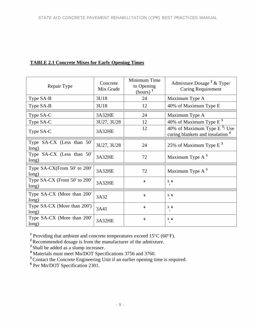
TABLE 2.1 Concrete Mixes for Early Opening Times
Repair Type Concrete Mix Grade
Minimum Time to Opening (hours) 1
Admixture Dosage 2 & Type/ Curing Requirement
Type SA-B 3U18 24 Maximum Type A Type SA-B 3U18 12 40% of Maximum Type E
Type SA-C 3A32HE 24 Maximum Type A Type SA-C 3U27, 3U28 12 40% of Maximum Type E 3
Type SA-C 3A32HE 12
40% of Maximum Type E 3/ Use curing blankets and insulation 4
Type SA-CX (Less than 50' long) 3U27, 3U28 24 25% of Maximum Type E 3
Type SA-CX (Less than 50' long) 3A32HE 72 Maximum Type A 5
Type SA-CX(From 50' to 200' long) 3A32HE 72 Maximum Type A 5
Type SA-CX (From 50' to 200' long) 3A32HE 6 5, 6
Type SA-CX (More than 200' long) 3A32 6 5, 6
Type SA-CX (More than 200') long) 3A41 6 5, 6
Type SA-CX (More than 200' long) 3A32HE 6 5, 6
1 Providing that ambient and concrete temperatures exceed 15°C (60°F). 2 Recommended dosage is from the manufacturer of the admixture. 3 Shall be added as a slump increaser. 4 Materials must meet Mn/DOT Specifications 3756 and 3760. 5 Contact the Concrete Engineering Unit if an earlier opening time is required. 6 Per Mn/DOT Specification 2301.
STATE AID CONCRETE PAVEMENT REHABILITATION (CPR) BEST PRACTICES MANUAL
- 10 -
Membrane Curing Compound Immediately after final finishing, all concrete shall be cured in accordance with Spec. 2531.3G2. Either Membrane Curing Compound meeting Specification 3754 AMS or Extreme Service Membrane Curing Compound meeting Specification 3755 shall be used. Only one type of curing compound shall be used on the entire project. Hudson sprayers may be used if the coverage rate is doubled and the curing material is from an agitated source.
Curing Compound 3754 AMS:
Specification 3754 AMS shall meet the following requirements:
White pigmented curing compound conforming to the requirements of ASTM Designation: C309, Type 2, Class B. The resin shall be 100 percent poly-alpha-methylstyrene. The curing compound shall conform to all requirements according to Table CC-1.
The shelf life of the product shall be 6 months from the date of manufacture. The product may be re-tested by the Mn/DOT Central Laboratory and re-approved, if the physical and chemical properties have not changed, for an additional six months. However, the maximum shelf life shall not exceed one year from manufacture date.
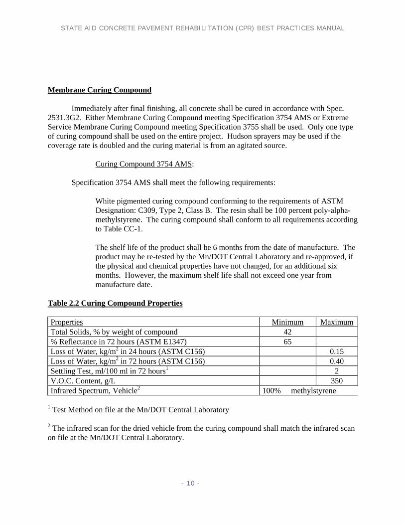
Table 2.2 Curing Compound Properties
Properties Minimum Maximum Total Solids, % by weight of compound 42 % Reflectance in 72 hours (ASTM E1347) 65 Loss of Water, kg/m2 in 24 hours (ASTM C156) 0.15 Loss of Water, kg/m2 in 72 hours (ASTM C156) 0.40 Settling Test, ml/100 ml in 72 hours1 2 V.O.C. Content, g/L 350 Infrared Spectrum, Vehicle2 100% � methylstyrene
1 Test Method on file at the Mn/DOT Central Laboratory 2 The infrared scan for the dried vehicle from the curing compound shall match the infrared scan on file at the Mn/DOT Central Laboratory.

STATE AID CONCRETE PAVEMENT REHABILITATION (CPR) BEST PRACTICES MANUAL
- 11 -
3. TYPE SA-A JOINT REPAIRS This work shall consist of repairing transverse joints, longitudinal joints or cracks to the specified width, as detailed in the Plan. The Contractor shall use the type of joint sealant and method of construction shown in the State Aid CPR Standard Details as shown below. The Contractor shall use only approved hot pour sealants as listed on the Concrete Unit Website at (www.mrr.state.dot.mn.us\pavement\concrete \products.asp) and only closed cell backer rod with hot pour sealants. The Contractor may use the following chart to estimate the amount of joint sealer required to fill the widths of joints listed in the plans for Types SA-A1, SA-A2 and SA-A3. Table 3.1 HOT POUR SEAL CHART - English
Joint Width (inches)
Sealant Bead Thickness (inches)
Backer Rod Diameter *
(inches)
Minimum Joint Depth
(inches) a b c d
Estimated ** Quantity
(Feet/Gallon)
Estimated ** Quantity
(lb./lin. ft.)
1/4
1/4
3/8
11/16
268
0.035
3/8
3/8
1/2
15/16
119
0.079 1/2
1/2
5/8
1-3/16
67
0.140
5/8
5/8
3/4
1-7/16
43
0.219 3/4
3/4
7/8
1-11/16
30
0.316
7/8
7/8
1
1-15/16
22
0.430 1
1
1-1/8
2-3/16
17
0.562
1-1/8
1-1/8
1-1/4
2-7/16
13
0.711 1-1/4
1-1/4
1-3/8
2-11/16
11
0.877
1-3/8
1-3/8
1-1/2
2-15/16
9
1.062 1-1/2
1-1/2
1-5/8
3-3/16
7
1.264
1-5/8
1-5/8
1-3/4
3-7/16
6
1.483 1-3/4
1-3/4
1-7/8
3-11/16
5
1.720
1-7/8
1-7/8
2
3-15/16
5
1.974 * Minimum backer rod diameter. Closed cell backer rod is required with hot pour sealants. * * Volumes will vary depending on joint design and joint irregularities. Sealing of joints wider than 1-1/4 inch is not recommended. The appropriate Type "B" or "C" repair should be performed. Joint Repair Type SA-A1 This work shall consist of cleaning and sawing transverse contraction joints or longitudinal joints to

STATE AID CONCRETE PAVEMENT REHABILITATION (CPR) BEST PRACTICES MANUAL
- 12 -
the specified width, as detailed in the plan, in preparation for resealing with hot pour sealant. Designer Notes: Joint Repair SA-A1 1. Measure and pay the restoration of cracks and joints through Type SA- B, or Type SA-C repairs under the pay item for the appropriate Type SA-A repair in addition to payment for the Type SA-B, or Type SA-C repair. 2. The designer must pick a joint width required for sawing existing transverse joints for SA-A1 detail. . It may be necessary to average joint widths over a number of joints (example 10 joints) to determine an optimal joint width to specify. Keep in mind that joints have varying widths during different seasons, generally closed in the summer and open in the winter. 3. This width along with table 3.1 will give the contractor an estimate of the pounds of sealant.
Figure 3.1 Sawing of joint before re-sealing. 4. It is highly unlikely that the longitudinal joints need to be re-sealed, but if the designer wants to reseal longitudinal joints it will probably be narrower than the transverse joint width. No distinction is made between Longitudinal and Transverse joint designations except for the width. All joints will be called Type SA-A1 with the proper joint width. 5. Keep in mind that if the joint width exceeds ¾ inch it can be expected to develop some noise from tire slap. This will depend on the traffic speed. Slower traffic roadways can tolerate a wider joint width. 6. The width picked should be used on all transverse joints, even where repairs have been performed. 7. Sealing of joints wider than 1-1/4 inch is not recommended. The appropriate Type SA-B or SA-C repair should be performed to make a narrower joint.

STATE AID CONCRETE PAVEMENT REHABILITATION (CPR) BEST PRACTICES MANUAL
- 13 -
8. Saw the existing joint 1/8 inch wider than the existing joint and to a depth as shown on the charts in table 3. Construction Notes: Joint Repair SA-A1 1. Measure and pay the restoration of cracks and joints through Type SA-B, or Type SA-C repairs under the pay item for the appropriate Type SA-A repair in addition to payment for the Type SA-B, or Type SA-C repairs. All repairs require lineal feet of joint repair plus the repair itself. 2. Hot pour kettles should be monitored for temperature to ensure correct placement temperature according to manufactures recommendations. 3. All joint resealing should occur after all repairs and diamond grinding are completed. 4. Clean, saw, and reseal joints and cracks in texture planed areas only after the diamond grinding texture planing operations are completed. 5. As approved by the Engineer, clean and remove waste material produced from cleaning, sawing, routing, planing or other operations from the adjacent pavement and remove from the Agency Right-of-Way to avoid unsightly buildup of waste or future maintenance problems such as but not limited to waste impairing drainage systems. 6. Remove all of the existing joint seal material from the joints insofar as it is possible with ripping teeth, wire brush, sawing or other reasonable equipment to the satisfaction of the Engineer. However, the Contractor shall not use equipment that will cause spalling of the pavement surface beyond the limits of the proposed sawed section. 7. Thoroughly clean all joints and cracks by water flushing immediately after sawing. 8. Do not place joint sealant when the air temperature is below 40°F, nor when the joint faces show signs of frost. 9. Assure that the joints or cracks are clean, dry, and free of all incompressible material before sealant is applied. The Contractor shall apply joint sealants in accordance with the Manufacturer’s recommendations. The Contractor shall use talc or tissue paper as necessary. One ply tissue paper is recommended. The Engineer may direct the Contractor to use a heat lance to dry joints and cracks prior to placing the joint sealant. The Contractor shall sandblast the joint faces after using the heat lance. 10. Fill joints or cracks to 1/8 inch below the pavement surface plus or minus 1/16 inch. Any overfilling will require removal and replacement by the Contractor at no cost to the Agency.

STATE AID CONCRETE PAVEMENT REHABILITATION (CPR) BEST PRACTICES MANUAL
- 14 -

STATE AID CONCRETE PAVEMENT REHABILITATION (CPR) BEST PRACTICES MANUAL
- 15 -
Joint Repair Type SA-A2 This repair is used for the cleaning and filling of transverse contraction joints or longitudinal joints without sawing the joint face clean. The joint shall be cleaned as much as practical of old joint material without widening the joint. The removable of the existing joint seal material from the joints can be accomplished with ripping teeth, wire brush, sawing or other reasonable equipment to the satisfaction of the engineer. However, the contractor shall not use equipment that will cause spalling of the pavement surface beyond the limits of the existing joint width. The contractor may use table 3 to determine the amount of joint material needed to fill the existing joint widths. Designer Notes: Joint Repair SA-A2 1. This detail is used when a designer decides not to saw and seal the existing joints. This detail is intended to be used on older pavements where resealing is not cost effective. 2. Designer must pick a joint width needed to clean and fill existing transverse joints for the SA-A2 detail. This is the only way a contractor can estimate the pounds of sealant required. 3. It is highly unlikely that the longitudinal joints need to be re-sealed, but if the designer wants to reseal longitudinal joints it will probably be narrower than the transverse joint width. No distinction is made between Longitudinal or Transverse joints except for the width when using these specifications. 4. Keep in mind that if the joint width on transverse joints exceeds ¾ inch it can be expected to develop some noise from tire slap. The severity of this noise will depend on the traffic speed. For example slower traffic roadways can tolerate a wider joint width. 5. The width picked should be used on all transverse joints, even where repairs have been performed. 6. Sealing of joints wider than 1-1/4 inch is not recommended. The appropriate Type SA-B or SA-C should be performed to make a narrower joint.

STATE AID CONCRETE PAVEMENT REHABILITATION (CPR) BEST PRACTICES MANUAL
- 16 -
Construction Notes: Joint Repair SA-A2 1. Hot pour kettles should be monitored for temperature to ensure correct placement temperature according to manufactures recommendations. 2. All joint resealing should occur after all repairs and diamond grinding operations are completed. 3. As approved by the Engineer, clean and remove waste material produced from cleaning, sawing, diamond grinding, or other operations from the adjacent pavement and remove from the Agency Right-of-Way to avoid unsightly buildup of waste or future maintenance problems such as but not limited to waste impairing drainage systems. 4. Remove all of the existing joint seal material from the joints insofar as it is possible with ripping teeth, wire brush, sawing equipment or other reasonable equipment to the satisfaction of the Engineer. However, the Contractor shall not use equipment that will cause spalling of the pavement surface beyond the limits of the existing joint section. 5. Do not place joint sealant when the air temperature is below 40°F, nor when the joint faces show signs of frost. 6. Assure that the joints are clean, dry, and free of all incompressible material before sealant is applied. The Contractor shall apply joint sealants in accordance with the Manufacturer’s recommendations. The Contractor shall use talc or tissue paper as necessary. One ply tissue is recommended. The Engineer may direct the Contractor to use a heat lance to dry joints and cracks prior to placing the joint sealant. The Contractor shall sandblast the joint faces after using the heat lance. 7. Fill joints or cracks to 1/8 inch below the pavement surface plus or minus 1/16 inch. Any overfilling will require removal and replacement by the Contractor at no cost to the Agency.

STATE AID CONCRETE PAVEMENT REHABILITATION (CPR) BEST PRACTICES MANUAL
- 17 -

STATE AID CONCRETE PAVEMENT REHABILITATION (CPR) BEST PRACTICES MANUAL
- 18 -
Crack Repair Type SA-A3 The intent of this repair is to saw and seal cracks, or those portions of cracks, between ¼ inch and 1inch wide with hot pour sealant. For cracks wider than 1 inch it is recommended that a Partial Depth Repair Type SA-BA be performed to make a narrower crack width. Designer Notes: Crack Repair SA-A3 1. Designer must pick a crack width needed for the SA-A3 detail. This is the only way a contractor can estimate the pounds of sealant required. It is advisable to try and use as few crack widths as possible to obtain the best price. 2. Keep in mind that if a transverse crack width exceeds ¾ inch, it can be expected to develop some noise from tire slap. This will depend on the traffic speed. Slower traffic roadways can tolerate a wider crack width. 3. Sealing of cracks wider than 1-1/4 inch is not recommended. The appropriate Type SA-B or SA-C should be performed to make a narrower crack. 4. Plan to widen the existing crack by sawing to a width 1/8 inch greater than the existing crack and to the depth listed in table 3.
Construction Notes: Crack Repair SA-A3 1. The pay item will be the actual lineal feet of crack sawed and sealed according to the width picked. 2. Hot pour kettles should be monitored for temperature to ensure correct placement temperature according to manufactures recommendations. 3. All crack resealing should occur after all repairs and diamond grinding are completed. 4. As approved by the Engineer, clean and remove waste material produced from cleaning, sawing, routing, diamond grinding or other operations from the adjacent pavement and remove from the Agency Right-of-Way to avoid unsightly buildup of waste or future maintenance problems such as but not limited to waste impairing drainage systems. 5. Thoroughly clean all cracks by water flushing immediately after sawing. 6. Do not place joint sealant when the air temperature is below 40°F, nor when the crack faces show signs of frost. 7. Assure that the cracks are clean, dry, and free of all incompressible material before sealant is applied. The Contractor shall apply joint sealants in accordance with the Manufacturer’s

STATE AID CONCRETE PAVEMENT REHABILITATION (CPR) BEST PRACTICES MANUAL
- 19 -
recommendations. The Contractor shall use talc or tissue paper as necessary. One ply tissue paper is recommended. The Engineer may direct the Contractor to use a heat lance to dry joints and cracks prior to placing the joint sealant. The Contractor shall sandblast the joint faces after using the heat lance. 8. Fill cracks to 1/8 inch below the pavement surface plus or minus 1/16 inch. Any overfilling will require removal and replacement by the Contractor at no cost to the Agency.

STATE AID CONCRETE PAVEMENT REHABILITATION (CPR) BEST PRACTICES MANUAL
- 20 -

STATE AID CONCRETE PAVEMENT REHABILITATION (CPR) BEST PRACTICES MANUAL
- 21 -
4. PARTIAL DEPTH REPAIR TYPE SA-B Partial Depth Repair Type SA-BA This repair shall be used for a shallow depth repair for deteriorated concrete that does not extend full depth through the pavement. The repair is a shallow 2-inch through 4-inch deep spot surface repair. The repair may be along a joint or crack, or at any location within a panel. This work shall consist of removing deteriorated concrete at designated Type SA-BA repair areas, furnishing, placing, and curing grade 3U18 concrete to the original slope and grade and re-establishing joints or cracks.
Figure 4.1 View of partial depth repairs after milling operations, both a joint and a crack. Designer Notes: Partial Depth Repair SA-BA
1. Payment will be calculated to the nearest square foot, with the realization most milling machines carry either a 10 inch or a 12 inch head. The width of any tangent section of Partial Depth Repair SA-BA shall be calculated as one foot wide. Extra width to accommodate contractor's equipment shall be at contractor's expense. All other odd shaped areas shall be calculated to the nearest square foot. Measurements shall be taken to the nearest tenth of a foot and rounded to the nearest square foot for payment of each individual repair area. Minimum size of repair for payment shall be one square foot for each individual repair.
2. If, after removal of the deteriorated concrete, the Engineer changes a Type SA-BA repair to a Type SA-C repair. The agency must pay the Contractor at a measured quantity of 40% of the Type SA-BA item plus the full cost for the Type SA-C repair. It is in the best interest of both parties that if this becomes a pattern then repairs marked as partial depth repairs should be changed to full depth repairs before any additional partial depth work is performed.

STATE AID CONCRETE PAVEMENT REHABILITATION (CPR) BEST PRACTICES MANUAL
- 22 -
Construction Notes: Partial Depth Repair SA-BA 1. Do not place concrete for Type SA-BA partial depth repairs at air temperatures below 40°F. 2. Do not use “Jackhammers” for partial depth removals. Removal hammers are limited to a maximum rated weight of 35 lbs. 3. Remove the concrete surface in the designated repair areas to a minimum depth of 2 inches and all deteriorated concrete removed to a maximum depth of one-half the pavement thickness. 4. Remove the concrete surface in the designated repair area by either milling transversely or longitudinally or by delineating the repair area by saw cuts and chipping back the saw cuts to a 30 - 60° angle. The Contractor shall chip-out secondary spalling resulting from milling at no cost to the agency, otherwise, chipping of the milled edges is not required. The Contractor shall not damage the dowel bars during the removal process. Any damage is the responsibility of the Contractor.
Figure 4.2 Picture of typical milling machine. 5. If inspection of existing dowel bars shows corrosion and if dowel bar cross-section loss due to corrosion is slight, the Contractor shall use MC-250 coating or a bridging material approved by the Engineer (duct tape). If the dowel bars are misaligned or exhibit corrosion to a greater degree, the Contractor shall cut or burn-off the bar. If this involves more than three adjacent dowels, the Contractor shall remove and replace the dowels using the appropriate repair detail. The placement of compression relief material is required to re-establish the joint.

STATE AID CONCRETE PAVEMENT REHABILITATION (CPR) BEST PRACTICES MANUAL
- 23 -
6. The contractor shall provide a compression relief saw cut or install compression relief material at the time of placement of the concrete to re-establish joints and cracks at their original locations.
Compressible Insert
3 in. min.
Patch
Spall
Compressible insert
1 in.
Figure 4.3 Location of compressible insert placed to bottom of patch.
Point Bearing
Expansion Expansion
Joint Closure Debonding
Popout & Breakage
Figure 4.4 Failure mode if compressible material is not installed properly.

STATE AID CONCRETE PAVEMENT REHABILITATION (CPR) BEST PRACTICES MANUAL
- 24 -
7. The contractor will provide and place a bonding grout to the prepared concrete repair surface consisting of 2 parts Portland cement and 1 part sand, mixed with sufficient water to form a slurry with the consistency of thick cream. The Contractor shall mix the grout by mechanical means and apply by brushing or scrubbing (with a stiff bristle broom) onto the in place concrete surface, followed by immediately placing 3U18 concrete after grouting. If the grout whitens, the Contractor shall sand blast and regrout. The life of the grout in the mixing container shall not exceed one hour. 8. The contractor shall furnish, place, finish and cure Grade 3U18 as replacement concrete for all Type SA-B repairs in accordance with these specifications.
Figure 4.5 Placement of Grade 3U18 patch material and compressible insert. 9. The contractor shall saw and seal joints and cracks involving Type SA-B repairs in accordance with the appropriate Type SA-A repair.

STATE AID CONCRETE PAVEMENT REHABILITATION (CPR) BEST PRACTICES MANUAL
- 25 -

STATE AID CONCRETE PAVEMENT REHABILITATION (CPR) BEST PRACTICES MANUAL
- 26 -
Partial Depth Repair Type SA-BE This repair is used for locations where the deterioration along a partial depth repair Type SA-BA exceeds T/2 in depth. Generally, this deterioration will extend to the bottom of the pavement. Most common for the ends of joints or cracks where the full depth deterioration, only extends up to 18 inches from the end of the repair. This repair is always used in conjunction with a Type SA-BA repair.
Figure 4.6 Common view of edge deterioration going to bottom of pavement. Designer Notes: Partial Depth Repair SA-BE 1. The engineer will never know by chaining or visual inspection if this repair is required. It is advisable to always bid an estimated quantity of Type SA-BA lineal feet as Type SA-BE repair. This way a price to pay will be established if the concrete is deteriorated below the T/2 depth of a pavement. 2. Payment will be calculated to the nearest square foot of the surface repair in the area of deterioration below T/2. All other odd shaped areas shall be calculated to the nearest square foot as best as possible. 3. It is recommended that if length of Type SA-BE is greater than 18 inches then the repair should be changed to a full depth repair.
Construction Notes: Partial Depth Repair SA-BE 1. Do not use “Jackhammers” for partial depth removals. Removal hammers are limited to a maximum rated weight of 35 lbs. 2. Placement of the Partial Depth Type SA-BA and the Partial Depth SA-BE grade 3U18 concrete is done at the same time.

STATE AID CONCRETE PAVEMENT REHABILITATION (CPR) BEST PRACTICES MANUAL
- 27 -

STATE AID CONCRETE PAVEMENT REHABILITATION (CPR) BEST PRACTICES MANUAL
- 28 -
5. FULL DEPTH REPAIR TYPE SA-C These repairs are used for the full depth replacement of a concrete pavement. Type SA-CA or Type SA-CD can be used on either a dowelled concrete pavement or a non-dowelled concrete pavement. Type SA-CA is generally used when the contractor does not own a gang-mounted drill device. The reinforcing bars can be drilled and grouted into the existing concrete face individually by hand. This is why the standard plate shows that the reinforcing bars can be placed at an angle. A gang-mounted drill device can be used to place reinforcing bars or dowels. Type SA-CD requires the use of a gang-mounted drill to correctly place the dowel bars parallel to the surface of the concrete pavement in both the vertical and horizontal directions. Full Depth Repair Type SA-CA This repair is to be used for the full depth repair of transverse contraction joints generally one lane wide, usually 12’. The ends are to be tied with reinforcing bars to lock into the existing pavement. The contractor must align a new transverse contraction joint in the new repair area to match an existing joint or crack in the adjacent lane of traffic. If the existing pavement is utilizing dowels for load transfer then a new dowel basket shall be placed in the repair. If the existing pavement is a non-dowelled pavement, then the contractor only has to saw a new joint in the repair area, matching any adjacent joint or crack.
Figure 5.1 View of gang mounted drills for placement of dowels.
STATE AID CONCRETE PAVEMENT REHABILITATION (CPR) BEST PRACTICES MANUAL
- 29 -
Designer Notes: Full Depth Repair Type SA-CA
1. If the deteriorated area is greater than 3’-6 inch in the direction of vehicle travel, payment for the extra square feet will be paid under Repair Type SA-CX.
2. Joint sealers are not required at the edges of this repair due to the locking action of the tie bars. But the contractor should seal any new transverse aggregate interlock joints with a Type SA-A repair, if existing joints are sealed.
3. This repair can be turned 90 degrees and used along a longitudinal joint if necessary. Construction Notes: Full Depth Repair Type SA-CA 1. This repair for a 12’ lane width will always measure 42 sq ft. For a 14’ turning lane the measurement will always be 49 sq ft. 2. Removal by the lifting method is the best way to avoid damage to the in place base material. If the concrete is broken and removed via a bobcat or similar equipment then the base shall be re-compacted as approved by the engineer. 3. If the pavement is under pressure from incompressibles then a ‘Relief Cut” should be done early in the morning to allow removal of the deteriorated concrete. 4. The contractor must drill 1inch diameter holes into the face of the existing concrete pavement and grout #25 [one inch diameter] reinforcement bars as shown on the standard plate. It is advisable, but not required to place these reinforcing bars at an angle to the in place concrete face. It is the intent that the angle will provide an additional interlock in conjunction with the grout. This drilling can be done by hand or with an approved drill rig. 5. The contractor must use either non-shrink grout or an epoxy anchorage for bonding reinforcing tie bars into the in-place concrete (For an approved products list, See www.mrr.dot.state.mn.us\pavement\concrete\products.asp). The Contractor shall clean and dry the drilled holes and place the bonding agent into the drilled hole in a manner that will completely fill the void, and then push the bar into the hole. The Contractor shall fill any voids with grout and smooth the area around the bar and check to assure that the bars are fully set prior to concrete placement. 6. For early opening of pavement to traffic, 4 hours or less, epoxy should be used in lieu of the grout for gluing of the dowel bars into the existing pavement.

STATE AID CONCRETE PAVEMENT REHABILITATION (CPR) BEST PRACTICES MANUAL
- 30 -

STATE AID CONCRETE PAVEMENT REHABILITATION (CPR) BEST PRACTICES MANUAL
- 31 -
Full Depth Repair Type SA-CD This repair is to be used for the full depth repair of transverse contraction joints generally one lane wide, usually 12’. The ends provide load transfer through the use of dowel bars drilled and grouted into the existing pavement. The dowels allow for the contraction and expansion of the concrete pavement. Full depth repair Type SA-CD requires the use of a gang-mounted drill to correctly place the dowel bars. The Contractor shall install individual dowel bars parallel to the in-place grade and the in-place roadway centerline within a tolerance of 1/8 inch in both the vertical and horizontal directions. If the repair area is not greater than 3’-6 inches in the direction of travel the contractor does not need to match the joint in the adjacent lane if isolation material is placed along the interface between the repair and the existing concrete pavement and any existing tie bars are removed. Designer Notes: Full Depth Repair Type SA-CD 1. If the deteriorated area is greater than 3’-6 inches in the direction of vehicle travel, the additional area is paid for by the extra square feet under Repair Type SA-CX. 2. This repair can be placed without a third joint in the middle of the repair by the use of isolation material to move the joint opening action around this repair. This will require the removal of any tie bars that may be exposed by the removal operation. If the repair exceeds 3-6 inches in the direction of vehicle travel, it would be questionable if the joint opening action will move around the repair. Construction Notes: Full Depth Repair Type SA-CD 1. This repair for a 12’ lane width will always measure 42 square feet. For a 14’ turning lane the measurement will always be 49 square feet. 2. Removal by the lifting method is the best way to avoid damage to the in place base material. If the concrete is broken and removed via a bobcat or similar equipment then the base shall be re-compacted as approved by the engineer. 3. If the pavement is under pressure from incompressibles in the joins then a ‘Relief Cut” should be done early in the morning to allow removal of the deteriorated concrete. 4. The contractor must drill smooth 18 inch by 1 inch diameter dowel bars with an approved gang-mounted drill assembly and grouted 9 inches into the face of the in place concrete slab as shown in the standard plate. The Contractor shall install individual dowel bars parallel to the in-place grade and the in-place roadway centerline within a tolerance of 1/8 inch in both the vertical and horizontal directions. Form release oil is a common release agent that will meet Mn/DOT Spec. # 3902, or grease placed by hand may be used on the dowel bars. 5. Joint sealant shall be placed at both ends of this repair if the existing pavement is sealed. 6. For early opening of pavement to traffic, 4 hours or less, epoxy should be used in lieu of the grout for gluing of the dowel bars.

STATE AID CONCRETE PAVEMENT REHABILITATION (CPR) BEST PRACTICES MANUAL
- 32 -

STATE AID CONCRETE PAVEMENT REHABILITATION (CPR) BEST PRACTICES MANUAL
- 33 -
Full Depth Repair Type SA-CX This repair is always used in conjunction with either a Type SA-CA or Type SA-CD repair if removal is required beyond the required 3'-6 inch length in the direction of vehicle travel. The final length of the SA-CX quantity is determined by subtracting the 3’-6 inch length of the SA-CA or SA-CD repair. This item covers the cost of placing and finishing the concrete required to fill the additional length required beyond the 3’-6 inch length covered under Type SA-CA or Type SA-CD. Designer Notes: Full Depth Repair Type SA-CX 1. The engineer must use either a SA-CA or a SA-CD repair with this item, there are no tie bars or dowel bars provided in the cost of this repair. 2. There is no limit on the length of this repair type. This item replaces MN/DOT type D repairs. 3. All quantities are measured to the nearest tenth of a foot and paid to the nearest square foot. This cost shall include any joint sawing, concrete cubic yards, concrete placing and finishing costs. While any additional joint sealing or dowel bars required are paid under the appropriate pay items. 4. The repair can extend past an existing joint or crack in the adjacent lane a maximum of 1.5 feet and not develop a random crack if the contractor places an isolation material along the longitudinal joint and he removes any existing tie bars. Construction Notes: Full Depth Repair Type SA-CX 1. Try to leave at least 1/3 of an existing panel in place with this repair. 2. The contractor shall replace any lost tie bars along the existing concrete longitudinal joint in the repair area and the contractor shall be paid under the item drill and grout reinforcing bars. If the existing longitudinal joint is a butt joint then no tie bars will be required. 3. If the contractor is placing dowel bars then it is imperative that some type of drilling jig be used to ensure that the bars are placed within 1/8 inch tolerance in both the horizontal and vertical directions. 4. Form release oil is a common release agent that can be used on the dowel bars and will meet Mn/DOT Spec. # 3902. Or the engineer can approve hand placed grease as a release agent. 5. If after removal the joint face is intact, the engineer can place dowels at one end of a repair to match an existing transverse joint and place reinforcing tie bars at the opposite end.

STATE AID CONCRETE PAVEMENT REHABILITATION (CPR) BEST PRACTICES MANUAL
- 34 -

STATE AID CONCRETE PAVEMENT REHABILITATION (CPR) BEST PRACTICES MANUAL
- 35 -
Spot Full Depth Repair Type SA-C1 This repair is to be used for small full depth concrete pavement replacements. Spot full depth repairs are designed to replace only a portion of a lane. If the engineer wants to replace a full lane width then use either Type SA-CA or Type SA-CD. The dimensions given are to be used as minimums and can be made larger if needed. The exploratory hole is to allow access to shut off valves or to locate items under the concrete pavement. Designer Notes: Spot Full Depth Repair Type SA-C1 1. This repair will fix one half of a lane on one side of joint or a mid panel problem. Repair listed as ‘A’ on the standard plate. Dowel bars will be required if this repair is used at a joint location. 2. This repair will also repair only a portion of a joint and repair a typical corner cracking problem. Repair listed as ‘B’ on the standard plate. 3. This repair will fix centerline spall repairs that are too large for a SA-BA partial depth repair. Repair listed as ‘C’ on the standard plate. 4. This repair will also allow a method to access traffic loop detectors under a pavement without a full depth repair. Repair listed as “D’ on the standard plate. Construction Notes: Spot Full Depth Repair Type SA-C1 1. All reinforcing bars shall not be placed closer than one foot from a pavement edge or an adjacent panel. 2. If the tie bars are drilled and grouted into the existing longitudinal joint by hand and they end up at an angle that is not a problem. 3. This repair shall be a minimum of 1.5 feet from the edge of any existing concrete. 4. All quantities are measured to the nearest tenth of a foot and paid to the nearest square foot. This cost shall include any joint sawing, concrete cubic yards, concrete placing and finishing costs.

STATE AID CONCRETE PAVEMENT REHABILITATION (CPR) BEST PRACTICES MANUAL
- 36 -

STATE AID CONCRETE PAVEMENT REHABILITATION (CPR) BEST PRACTICES MANUAL
- 37 -
Utility Trench Full Depth Repair Type SA-C2 This repair is intended to replace a concrete pavement over utility trench excavations.
Figure 5.2 View of completed full depth repair over utility. Designer Notes: Utility Trench Full Depth Repair Type SA-C2 1. This repair is intended to be primarily be used by utility companies that have to gain access under a concrete pavement. This repair will include all costs above the bottom of the 12 inches of aggregate base. All excavation and utility repairs below this line must be paid under a separate bid item. 2. If necessary to facilitate traffic concerns the contractor can use a fast setting concrete mix according to the mixes approved in table one of this manual for full depth repairs. 3. The intent of placing a steel reinforcing mat and making the repair concrete two inches thicker than the existing concrete is to recognize the difficulty in obtaining excellent compaction is such a small area. 4. As an option to the backfill mentioned in the standard plate the engineer can order a Controlled Low Strength Material from a local Ready Mix supplier. The CLSM is a fly ash concrete mix that will be an excavatable material. The local Ready Mix producer shall be permitted and certified by the Aggregate Ready Mix Association of Minnesota, to place this material according to MPCA standards Construction Notes: Utility Trench Full Depth Repair Type SA-C2 1. If this is the only repair being performed then traffic control is an incidental cost item to execute this repair. 2. It is not necessary to saw and seal the joint at the edges of the repair, but it will be necessary to round the concrete with at lest a ¼ inch concrete finishing tool to prevent spalling and chipping of the repair. 3. All quantities are measured to the nearest tenth of a foot and paid to the nearest square foot. This cost shall include any joint sawing, concrete cubic yards, concrete placing and finishing costs.

STATE AID CONCRETE PAVEMENT REHABILITATION (CPR) BEST PRACTICES MANUAL
- 38 -

STATE AID CONCRETE PAVEMENT REHABILITATION (CPR) BEST PRACTICES MANUAL
- 39 -
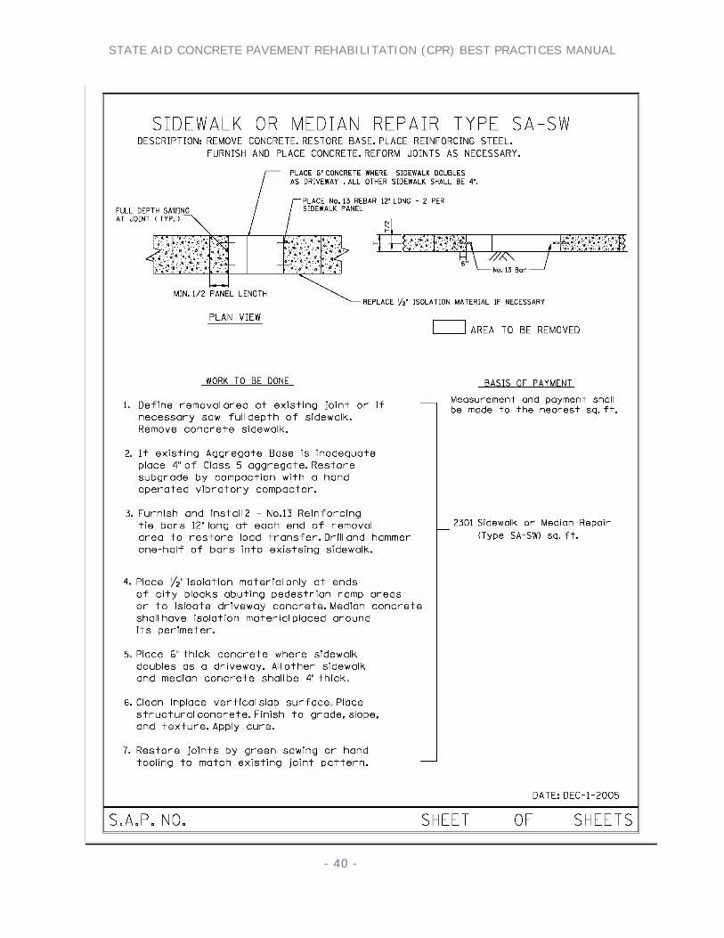
6. SIDEWALK OR MEDIAN REPAIR TYPE SA-SW This repair details how to replace sidewalk or median concrete. Designer Notes: Sidewalk or Median Repair Type SA-SW 1. Generally this concrete is four inches thick unless otherwise detailed in the plans. Construction Notes: Sidewalk or Median Repair Type SA-SW 1. Isolation material should be placed next to any building or frost protected structure. 2. Isolation material should be placed around the perimeter of any median concrete that is being repaired. 3. Contraction joints shall be placed to match any adjacent sidewalk joints or concrete pavement, but generally not longer than five feet. 4. Replacement of any isolation material that is damaged during the removal operations will be required in order to match with the existing isolation material on either side of the repair area. 5. Tie bars can be hammered into place. 6. All quantities are measured to the nearest tenth of a foot and paid to the nearest square foot. This cost shall include any joint sawing, concrete cubic yards, concrete placing and finishing costs.
STATE AID CONCRETE PAVEMENT REHABILITATION (CPR) BEST PRACTICES MANUAL
- 40 -

STATE AID CONCRETE PAVEMENT REHABILITATION (CPR) BEST PRACTICES MANUAL
- 41 -
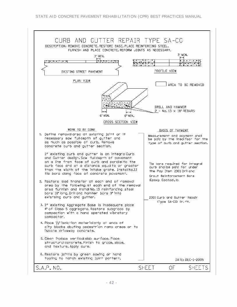
7. CURB AND GUTTER REPAIR TYPE SA-C Curb and Gutter Repair Type SA-CG This repair details how to remove and replace curb and gutter sections. Designer Notes: Curb and Gutter Repair Type SA-CG 1. This plate is used to detail how to remove and replace existing curb and gutter sections which are experiencing drainage problems. 2. The repair shall leave as a minimum three feet of the existing curb and gutter in place. Otherwise remove back to the nearest existing joint. 3. If repairing an integral curb and gutter section (C & G paved with a parking lane) you must cut into the concrete pavement on a line parallel to the curb face and at a distance equal to or greater than one foot from the face of the curb. You must also pay for reinforcing tie bars placed along this line to lock the repair into the existing concrete pavement. The number of bars shall match the spacing along an existing longitudinal joint, generally a 30” or 36” spacing, but a minimum of 2 bars shall be required in each repair area. Construction Notes: Curb and Gutter Repair Type SA-CG 1. Care must be taken to restore area behind the curb and gutter after replacement. 2. Payment shall be the nearest lineal foot of removal area and any additional tie bars when an integral curb design is being repaired. 3. Tie bars into curb and gutter section can be hammered into place. 4. When repairing an integral curb and gutter you must pay for any tie bars placed along the face of the concrete pavement. And these tie bars must be grouted into the existing concrete pavement.
STATE AID CONCRETE PAVEMENT REHABILITATION (CPR) BEST PRACTICES MANUAL
- 42 -

STATE AID CONCRETE PAVEMENT REHABILITATION (CPR) BEST PRACTICES MANUAL
- 43 -
Catch Basin Repair Type SA-CB This repair details how to reset catch basins intakes and the adjacent curb and gutter. This repair does not include any cost for repairing anything under the curb and gutter. If it is required to repair or reset storm sewer pipes or related structures the engineer will need to pay for that work under a different pay item. Designer Notes: Catch Basin Repair Type SA-CB 1. The concrete will generally be placed thicker near the intake to allow the gutter pan sections to
rest on either the underground structure or expansion rings. 2. The measurement for pay shall be to the nearest lineal foot and shall include the length of the
catch basin structure. 3. If repairing an integral curb and gutter section (paved with the parking lane) you must cut
into the concrete pavement on a line parallel to the curb face and at a distance equal to or greater than the width of the intake grate. You must also pay for reinforcing tie bars placed along this line to lock the repair into the existing concrete pavement. The number of bars shall match the spacing along an existing longitudinal joint, generally a 30” or 36” spacing, but a minimum of 2 bars shall be required in each repair area.
Construction Notes: Catch Basin Repair Type SA-CB
1. Joints may be hand tooled as is done with normal curb and gutter construction techniques.
2. Tie bars into the curb and gutter section can be hammered into place.
3. Care must be taken to restore area behind the curb and gutter after replacement. 4. When repairing an integral curb and gutter you must pay separately for any tie bars placed along the face of the concrete pavement. These tie bars must be grouted into the existing concrete pavement.

STATE AID CONCRETE PAVEMENT REHABILITATION (CPR) BEST PRACTICES MANUAL
- 44 -
STATE AID CONCRETE PAVEMENT REHABILITATION (CPR) BEST PRACTICES MANUAL
- 45 -
8. DOWEL BAR RETROFIT TYPE SA-DB This repair is to be used for re-establishing load transfer at cracks or joints. This repair may be considered when the concrete is structurally sound and the main deficiency of the pavement is load transfer. The repair saws, or mills, slots, places dowels in the slots, then places patching material in the slots and around the dowel bars. If the concrete panel is sound then this repair should be considered an option in lieu of a full depth repair. Designer Notes: Dowel Bar Retrofit Type SA-DB 1. If the roadway has two-way traffic with functioning tie bars at centerline then it will only be necessary to place retrofit dowels in the outside wheel paths. Generally three retrofits per wheel path staring at 18 inches from the outside edge of the roadway lane. 2. If the roadway is a multilane facility then it will be necessary to place three retrofit dowels in each wheel path in order to provide adequate load transfer. Construction Notes: Dowel Bar Retrofit Type SA-DB
1. The Contractor shall use a “Mn/DOT Approved Non-Shrink Rapid Set Concrete Material for Dowel Bar Retrofit Repairs” conforming to ASTM C 928 and the requirements on file in the Mn/DOT Concrete Engineering Unit. The list of approved products may be found on the Mn/DOT Concrete website at www.mrr.dot.state.mn.us/pavement/concrete/concrete.asp or by contacting the Concrete Engineering Unit. This material may be extended with CA-80 aggregate as specified by the manufacturer, as backfill material. Other non-shrink rapid set material may be used if approved by the engineer. Any material submitted for approval must be received by the engineer a minimum of 30 days prior to the start of work. Any material submitted after that time will not be evaluated.
2. The release agent used to provide a bond break on the dowel bars shall be a liquid
membrane-forming compound conforming to Mn/DOT 3902; e.g., “Duo Guard” by W.R. Meadow or an approved equal. The material shall be applied to the dowel bars prior to their placement in the slots.
3. After the concrete is removed from the slot, the bottom and sides of the crack shall be
sealed with a Mn/DOT approved silicone joint sealant material and allowed to cure for a minimum of 2 hours or until it is tack free (according to the manufacturer's recommendations) prior to placing the patching material. This should be done in a manner sufficient to keep the patching material from leaking into the crack/joint.

STATE AID CONCRETE PAVEMENT REHABILITATION (CPR) BEST PRACTICES MANUAL
- 46 -
4. The 1 1/4 inch by 15 inch dowel bars shall be plain steel bars that are 100% epoxy coated on all surfaces and shall conform to Mn/DOT 3302.
5. The dowel bars shall be provided with tight fitting, clear plastic end caps that will allow
for a 1/4 inch expansion movement of the bar at each end. The Contractor shall submit samples to the Engineer for approval prior to ordering the end caps.
6. Compressible foam core board constructed of closed cell foam and faced with poster
board material shall be used to reestablish the crack/joint the full width and depth of the slot, as shown in the Plan detail. The material shall be at least 1/4 inch thick and a minimum of 1/8 inch thicker than the crack/joint at the surface to ensure no leakage of patching material into the crack. Multiple pieces will not be permitted to obtain the proper thickness. The Contractor shall submit a sample to the Engineer for approval prior to use.
7. Each dowel bar shall be provided with two, nonmetallic support chairs similar to those
shown in the Plans. The support chairs shall provide a minimum of 1/2 inch clearance between the bottom of the dowel and the bottom of the slot. The Contractor shall submit samples of the supports to the Engineer for approval prior to ordering the support chairs.
8. Immediately after final finishing, all concrete shall be coated with a modified membrane
cure. The material shall meet the requirements of Mn/DOT 3754AMS. Hudson sprayers may be allowed on a performance basis if the coverage rate is doubled and the curing material is from an agitated source. Water based curing compounds shall not be used.
9. The Contractor shall provide a test operation consisting of complete dowel bar retrofit at
a site directed by the Engineer prior to start up of major operations. There will be 24 retrofit dowels in the test operation. 24 hours after completion of the test operations, the Contractor shall take three 6 inch diameter full depth cores as directed by the Engineer to determine the completeness of the removal and installation operations. If the placement is in accordance with the Plans, the Mn/DOT Standard Specifications, and these Special Provisions; and if the Contractor’s retrofitting operation has not damaged the surrounding in place concrete; then, upon approval from the Engineer, the Contractor may begin production operations and shall proceed on a performance basis. Complete removal and replacement of the dowel installation will be necessary where the core samples are taken. The work in this paragraph shall be paid at the unit price for dowel bar retrofit. The working days for the test section are built into the total Contract Time.
10. If approval of the retrofitting operation is not given, the Engineer may order the Contractor to change their operations and complete another test operation to determine if the Contractor’s changes are acceptable. All costs for the additional test section shall be borne by the Contractor. Contractor time will not be extended for the additional test section. For example, if the Contractor chooses to mill the slot for the retrofit and the mill cracks the in place concrete underneath the slot or does unacceptable damage to the pavement surface, the Engineer will order a different piece of equipment for the removal operation.

STATE AID CONCRETE PAVEMENT REHABILITATION (CPR) BEST PRACTICES MANUAL
- 47 -
11. Traffic control for the test operation shall be in accordance with “Temporary Traffic Control Zone Layouts or as shown in the Plans. Complete removal and replacement of the dowel installation will be necessary where the core samples were taken. The work in this paragraph shall be incidental to the Contract and no direct payment will be made.
12. The Contractor shall dowel bar retrofit the mainline joints and/or midpanel cracks on the
roadway.
13. The slot shall be parallel with the centerline and surface of the in place roadway. Pickup and removal of debris concrete shall be immediate. It shall include the use of a high power, mobile, vacuum cleaning machine capable of removing all displaced material with a minimum of dust. Approximate slot dimensions are:
14. 26 inches by 2 ½ inches at the pavement surface. 15. 16 inches by 2 ½ inches at the bottom of the slot.
16. All removed material or material generated by the Contractor’s operations of any kind
shall be disposed of off the Right-of-Way in accordance with Mn/DOT 2104.3C3.
17. The Contractor shall use equipment approved on a performance basis by the Engineer to ensure that the bottom of the slot is flat. If jackhammers are used in removal, they shall be limited to a weight of 30 pounds or less.
18. The bottom of the slots should be sufficiently cleaned with a jackhammer to allow the
dowel bar assembly to sit parallel to the pavement surface.
19. All slots in each wheel path of a midpanel crack or joint shall be sawn at the same time. Depth shall be at the dimension shown in the Plan with a tolerance of +/- 1/8 inch. The Contractor must be aware that due to the skew of the cracks that it is anticipated that the length of the slot will usually be longer than that shown in the Plans. No additional compensation will be made for this additional length for any component of the dowel bar retrofit. If the Contractor uses a saw to cut the slot, the saw shall have a minimum of two blades sawing concurrently on each slot. If under breaking of the slab occurs, three or more blades will be required.
20. Any water residue or saw slurry created by removal operations shall be contained and
vacuumed immediately from the road surface.
21. The Contractor shall sandblast the slot after the concrete removal operations are complete to remove any loosened material and to roughen the side faces of the slot. There should be no evidence of sawing residue on the vertical sawed faced or bottom of the slot. The vertical sawed faces should be rough to the touch after sand blasting. The Contractor may recommend alternative methods for said roughening for approval by the Engineer. Additional sandblasting will be required if the slots become wet from any source after initial sand and air blasting.

STATE AID CONCRETE PAVEMENT REHABILITATION (CPR) BEST PRACTICES MANUAL
- 48 -
22. All exposed surfaces and cracks shall be further cleaned with a “moisture and oil free”
high pressure air-blasting lance, 100 psi minimum, immediately before beginning the sealing work. The Contractor shall protect traffic from sand and air blasting in a manner approved by the Engineer on a performance basis.
23. Immediately prior to placement of the dowel bar and filler material, the Contractor shall
seal the existing transverse joint/crack within the slot as shown in the Plans. The silicone sealant shall be placed so as to provide a smooth surface and tight fit for the compressible foam core board. The joint/crack shall be sealed sufficiently to prevent any of the grouting material from entering the crack.
24. Dowel bars shall be lightly coated with an approved release agent, fitted with the
compressible Styrofoam or cardboard material, the support chairs, and the 1/4 inch expansion caps on both ends just prior to installation. The dowel bars shall be placed parallel to the centerline and pavement surface, all to a tolerance of 8 inch.
25. Chairs for supporting and holding the dowel bar shall hold the dowel bar in place during
placement and consolidation of the concrete placement and vibratory consolidation. If the bar exceeds the 1/8 inch tolerance mentioned above after all operations are completed, the dowel bar installation shall be removed and replaced at the Contractor’s expense.
26. The compressible foam core board shall be placed to maintain the transverse crack as
shown in the Plans. The filler material shall remain in position and tight to all edges during placement of the concrete. If the filler material shifts, for any reason, during construction operations, the dowel bar installation shall be removed and replaced at the Contractor’s expense.
27. The approved non-shrink rapid set concrete material shall be placed in the slot. All
concrete placed in the slots shall be vibrated with a "spud" type vibrator prior to finishing to insure proper consolidation. The finished concrete shall be flush with the adjacent in place concrete with a tolerance of 1/16 inch high and 0 inches low.
28. If for any reason, shrinkage cracks occur in the repair after placement, the work will be
rejected and completely redone at the Contractor’s expense.
29. Traffic by the public or Contractor will not be permitted on the newly placed concrete patching material until adequate strength has been achieved, according to the manufacturer's recommendations. No traffic will be permitted until the complete operation is finished and approval is granted by the Engineer.
30. Any damage to the pavement, joints, or shoulders due to the Contractor’s operations shall
be repaired by the Contractor at their expense.

STATE AID CONCRETE PAVEMENT REHABILITATION (CPR) BEST PRACTICES MANUAL
- 49 -

STATE AID CONCRETE PAVEMENT REHABILITATION (CPR) BEST PRACTICES MANUAL
- 50 -

STATE AID CONCRETE PAVEMENT REHABILITATION (CPR) BEST PRACTICES MANUAL
- 51 -
9. DRILL AND GROUT REINFORCEMENT BARS This work shall consist of drilling, grouting, and inserting reinforcement bars in accordance with the provisions of Mn/DOT 2301, and the following: Measurement will be made by the weight of reinforcement bars that are furnished, installed, and grouted in place as specified. Payment will be made under Item 2301.608 (Drill and Grout Reinforcement Bars) at the Contract bid price per pound, which shall be payment in full for all costs incidental thereto. This pay item is to be used for placement of R-Bars not required by the appropriate standard plate, such as the tie bars required to tie an integral curb and gutter repair into the concrete pavement.

STATE AID CONCRETE PAVEMENT REHABILITATION (CPR) BEST PRACTICES MANUAL
- 52 -
10. DIAMOND GRINDING (TEXTURE-PLANING) REPAIR TYPE SA-DG Diamond grinding is a concrete pavement restoration technique that corrects a variety of surface imperfections on concrete pavements. Diamond grinding should be used in conjunction with other Concrete Pavement Rehabilitation (CPR) techniques. Diamond grinding restores rideability by removing surface irregularities caused by pour construction practices, slab curling, faulting, and the construction of other CPR repairs. The immediate effect of diamond grinding is a significant improvement in smoothness of a pavement. Another very important effect of diamond grinding is the significant increase in surface macro-texture and consequent improvement in skid resistance, noise reduction and safety.
Figure 10.1 View of completed diamond ground section over manhole. Designer Notes; Diamond Grinding Repair Type SA-DG 1. Some of the surface imperfections that can be addressed by diamond grinding include:
a. Faulting at joints and cracks. b. Built-in or construction roughness. c. Polished concrete surface exhibiting inadequate macro texture. d. Wheel Path rutting caused by studded tires. e. Unacceptable tire impact noise levels. f. Slab warping caused by moisture gradient and construction curling. g. Inadequate transverse slope.
2. This work shall consist of planing and texturing the surface of the existing concrete pavement in a longitudinal direction utilizing a Target 3802 or Boart Longyear PC 5000 diamond grinding machine or approved equal as directed by the Engineer. The intent of this
STATE AID CONCRETE PAVEMENT REHABILITATION (CPR) BEST PRACTICES MANUAL
- 53 -
specification is to improve skid resistance, correct surface defects and promote drainage. Existing joint seals may be removed prior to or in conjunction with this operation. However, tolerances for joint sealing shall be measured from the resulting planed surface.
Construction Notes; Diamond Grinding Repair Type SA-DG 1. Approximately 95% of the entire surface area of pavement designated shall be planed in a manner that results in uniform texture. The surface shall have a finished texture with grooves between 0.097 inches and 0.130 inches, and 0.080 inches and 0.115 inches apart. The width of kerf shall be adjusted to maximize skid resistance. The grooves shall not be less than 0.031 inches or more than 0.115 inches in depth. The actual textured area of any selected 2 foot by 100 foot longitudinal area of pavement shall not be less than 98% of the selected area. 2. All concrete repairs to the existing concrete pavement must be made before the diamond grinding concrete-texture planing operation is commenced. All repairs, except Type SA-CX repairs in excess of 30 feet shall have a texture-planed surface. Those Type SA-CX repairs in excess of 30 feet shall have a 15 foot minimum texture-planed runout at each end to eliminate bumps. 3. Residue and excess water resulting from this operation shall be removed from the roadway by vacuuming. Residue and water shall not be permitted to either flow across lanes occupied by traffic or to flow into gutters or other drainage facilities.

STATE AID CONCRETE PAVEMENT REHABILITATION (CPR) BEST PRACTICES MANUAL
- 54 -

STATE AID CONCRETE PAVEMENT REHABILITATION (CPR) BEST PRACTICES MANUAL
- 55 -
11. SLABJACKING This section was reprinted with permission from the American Concrete Pavement Association. ACPA NOTE: In the past, slabjacking has sometimes caused uneven slab support and even slab cracking. However, with proper procedures and materials a contractor can lift the pavement back into position and effectively restore support to the slab. Slabjacking has also been used in combination with precast concrete panels for quick, overnight or weekend repairs to roadways and airfields. The contractor must exercise caution, however, to avoid over pumping and distortion of the pavement ride quality. Minor faulting and slab displacement may be more economically corrected using diamond grinding. 1. Purpose. The purpose of slabjacking is to raise a slab in place permanently, prevent impact loading, correct faulty drainage, and prevent pumping at transverse joints by injection of a grout under the slab. The grout fills voids under the slab, thereby restoring uniform support (Figure 6.1). When necessary, it can also be used to raise the slab. This work must be done by an experienced contractor due to work complexity and specialized equipment required.
Grout
Grout will fill void underpavement without lifting it
InitialGrout
Completed
Figure 11.1 Injecting grout. 2. Need for Slabjacking. Slabjacking should be considered for any condition that causes non-uniform slab support, such as embankment settlement, settlement of approach slabs, settlement over culverts or utility cuts, voids under the pavements, differences in elevation of adjacent pavements, joints in concrete pavements that are moving or expelling water or soil fines, and pavement slabs that rock or teeter under traffic. 3. Location of Injection Holes. Location of injection holes must be determined in the field. The

STATE AID CONCRETE PAVEMENT REHABILITATION (CPR) BEST PRACTICES MANUAL
- 56 -
jacking crew superintendent normally locates the holes and must take into consideration the size or length of the pavement area to be raised, the elevation difference, subgrade and drainage conditions, location of joints or cracks, and the manner in which the slabs will be tilted or raised. As a general rule, holes should not be placed less than 12 in. or more than 18 in. from a transverse joint or slab edge. The holes should not be placed more than 6 ft center to center, so that not more than approximately 25 to 30 ft2 of slab is raised by pumping any one hole. Additional holes may be required if the slab is cracked. The proper location of holes varies according to the defect to be corrected (Figure 6.2). For slabjacking a joint where faulting has not yet occurred, a minimum of two holes can be used. For slabjacking a joint where one corner of the slab has faulted, the hole at the low corner should be set back to avoid raising the adjacent slab. Where the pavement has settled and the slabs are in contact with the subbase, a single hole located in the middle of the panel may be sufficient. 4. Drilling Holes. Holes that are 1.25 to 2.0 in. in diameter are drilled by pneumatic drills, core drills, or other devices which are capable of drilling grout injection holes through the concrete pavement and the base material. The equipment must be in good condition and operated in such a manner that the holes are vertical and round. The down feed pressure, whether by hand or mechanical means should not exceed 200 psi. Where the concrete pavement is tight against the base material, the use of an airline or blow pipe may be necessary to form a cavity under the pavement slab for the grout pressure to take effect. Where the pavement is placed and bonded to a cement treated or other stabilized base material, grout holes should be drilled completely through the base material. The grout should be injected below the base material rather than between the pavement and base material. 5. Grout Mixtures. A variety of materials have been successfully used for slabjacking. These materials range from cement/fly ash grouts to expansive polyurethane foam. Polyurethane materials are more costly but are considered more durable, and must be applied using properly trained personnel. Pozzolan and fly ash based grouts generally consist of three to seven parts fine aggregates or a mixture of aggregate and pozzolans or fly ash to one part portland cement with enough water to produce the desired consistency. Wetting agents or other additives may also be used to increase the flowability. The use of a wetting agent lubricates the grout and permits runs of up to 6 ft , and it also tends to reduce “pyramiding” (a stiff grout may form a pyramid under the slab, leaving unfilled cavities). A definite method of proportioning the grout mixture should be used to ensure uniform consistency. The proper consistency to be used for any given condition is best determined by experience. Generally, a mix of stiff consistency is used to raise the pavement slabs and a more fluid mix is used for filling voids. The consistency should be checked by a flow cone (CRD-C 611 / ASTM C 939) at least twice each day. Typical flow-cone times vary between 16 to 30 seconds depending on the type of materials used in the grout mix. Strength requirements of the grout mixture should be specified. A common requirement is 600 psi at 7 days as determined by ASTM C 39. 6. Grout Pumping. Pumping and jacking operations should normally start at the lowest point in a depressed area and work outward in both directions (Figure 6.3). Pumping progresses by lowering into successive holes an injection pipe connected to the discharge hose of the grout pump. An expanding rubber packer is used to seal the open space between the pipe and the drill

STATE AID CONCRETE PAVEMENT REHABILITATION (CPR) BEST PRACTICES MANUAL
- 57 -
hole. The injection pipe must not extend below the bottom of the pavement and it must be equipped with a return line to circulate the grout while no grout is being placed. Lifting should be done in increments of about 0.25 in. with frequent changes in injection locations to keep slab stresses at a minimum and avoid cracking. The rate of grout injection should be uniform and as slow as possible, usually a minimum of 0.5 ft3 per minute to a maximum of 2.0 ft3 per minute. Initial pumping is normally at the lower rate and is increased as lifting progresses. As the desired elevation is approached, the lifting rate should be reduced. When grout is extruded from joints, cracks, or from the pavement edge before the target elevation is reached, regrouting in new drill holes and additional slabjacking will be necessary. Gauge pressures for slabjacking are normally in the range of 75 to 200 psi with short pressure surges up to 600 psi to initiate lifting of bonded slabs. Constant observation and analysis of pressure behavior is the most important single factor affecting good slabjacking. A rapid increase could signal a stoppage of flow that could be followed by a buildup of pressure and excessive lift and cracking, if pumping continues. A sudden reduction of pressure could indicate a loss of lift due to subsurface leakage. In slabjacking operations, the temperature is important when raising slabs to correct faulted joints or other elevation differences. If the temperature is high, the concrete may be in compression at the slab ends and may not be free to move. This may require freeing the joints by sawing to complete the lifting process.
PUMPING STARTS AT LOWEST POINT AND WORKS OUTWARD IN BOTH DIRECTIONS
9 4,8
,10
1,3
,5,7
,11
2,6
,12
13
Figure 11.2 Grout pumping. 7. Elevation Control During Jacking. Before slabjacking operations are started, some method of controlling the amount the slab is to be raised and the finished elevation of the pavement should be determined. For correcting faulted slabs, a straight edge may be used. For short dips up to approximately 50 ft in length, a tight stringline is adequate provided the joints are true and plane with those of the adjacent pavement (Figure 6.4). For dips in excess of 50 ft in length, an engineer’s level and rod should be used to check the profile well beyond the dip. This will avoid building a bulge into the pavement.
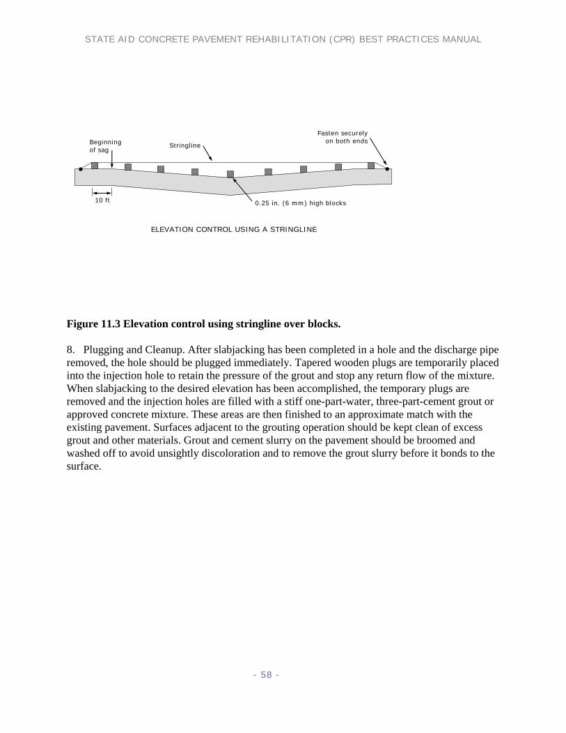
STATE AID CONCRETE PAVEMENT REHABILITATION (CPR) BEST PRACTICES MANUAL
- 58 -
ELEVATION CONTROL USING A STRINGLINE
Fasten securelyon both endsBeginning
of sag
10 ft 0.25 in. (6 mm) high blocks
Stringline
Figure 11.3 Elevation control using stringline over blocks. 8. Plugging and Cleanup. After slabjacking has been completed in a hole and the discharge pipe removed, the hole should be plugged immediately. Tapered wooden plugs are temporarily placed into the injection hole to retain the pressure of the grout and stop any return flow of the mixture. When slabjacking to the desired elevation has been accomplished, the temporary plugs are removed and the injection holes are filled with a stiff one-part-water, three-part-cement grout or approved concrete mixture. These areas are then finished to an approximate match with the existing pavement. Surfaces adjacent to the grouting operation should be kept clean of excess grout and other materials. Grout and cement slurry on the pavement should be broomed and washed off to avoid unsightly discoloration and to remove the grout slurry before it bonds to the surface.

STATE AID CONCRETE PAVEMENT REHABILITATION (CPR) BEST PRACTICES MANUAL
- 59 -
12. QUANTITY SHEETS
State Aid Concrete Pavement Rehabilitation Type SA-A Repairs, Sidewalk and Curb and Gutter Repairs
SAP Road Date
____________________ ____________________ ____________________
Location
Lt
Rt
Field Measurement
Type SA-A1 Lin Ft.
Type SA-A2Lin Ft.
Type SA-A3Lin Ft.
Type SA-SW Sq. Ft.
Type SA-CG Lin Ft.
Type SA-CB Lin. Ft.
Measured By Computed By Checked By Page __________ of ____________ Pages
Sheet Totals
Daily Totals Pay Quantity

STATE AID CONCRETE PAVEMENT REHABILITATION (CPR) BEST PRACTICES MANUAL
- 60 -
State Aid Concrete Pavement Rehabilitation Type SA-B Repairs, Dowel Bar Retrofit and Diamond Grinding
S.P. T.H. Date
_______________________ _______________________ _______________________
Location
Lt
Rt
Field Measurement
Type SA-BA Sq Ft.
Type SA-BE Sq. Ft.
Type SA-DB Each
Type SA-DG Sq. Yd.
Sheet Totals
Daily Totals
Measured By Computed By Checked By Page __________ of ____________ Pages Pay
Quantity

STATE AID CONCRETE PAVEMENT REHABILITATION (CPR) BEST PRACTICES MANUAL
- 61 -
STATE AID CONCRETE PAVEMENT REHABILITATION FULL DEPTH REPAIRS & MISC.
Sap. Road. Date
Location
Lt.
Rt.
Field Measurement
Type SA-CA Sq. Ft.
Type SA-CD Sq. Ft.
Type SA-CX Sq Ft.
Type SA-C1 Sq. Ft.
Type SA- C2 Sq. Ft.
2301. D & G Tie Bars Lb.
2301. Reinf Bars (Epoxy) Lb.
2301. Dowel Bars Each
Sheet Totals
Daily Totals
Measured By Computed By Checked By Page ______________ of _____________ Pages
Pay Quantity